US6464459B2 - Lifting platform with energy recovery - Google Patents
Lifting platform with energy recovery Download PDFInfo
- Publication number
- US6464459B2 US6464459B2 US09/871,597 US87159701A US6464459B2 US 6464459 B2 US6464459 B2 US 6464459B2 US 87159701 A US87159701 A US 87159701A US 6464459 B2 US6464459 B2 US 6464459B2
- Authority
- US
- United States
- Prior art keywords
- air
- lift
- pressure
- turbine
- fluid flow
- Prior art date
- Legal status (The legal status is an assumption and is not a legal conclusion. Google has not performed a legal analysis and makes no representation as to the accuracy of the status listed.)
- Expired - Fee Related
Links
Images


Classifications
-
- F—MECHANICAL ENGINEERING; LIGHTING; HEATING; WEAPONS; BLASTING
- F15—FLUID-PRESSURE ACTUATORS; HYDRAULICS OR PNEUMATICS IN GENERAL
- F15D—FLUID DYNAMICS, i.e. METHODS OR MEANS FOR INFLUENCING THE FLOW OF GASES OR LIQUIDS
- F15D1/00—Influencing flow of fluids
-
- B—PERFORMING OPERATIONS; TRANSPORTING
- B64—AIRCRAFT; AVIATION; COSMONAUTICS
- B64C—AEROPLANES; HELICOPTERS
- B64C11/00—Propellers, e.g. of ducted type; Features common to propellers and rotors for rotorcraft
- B64C11/001—Shrouded propellers
-
- B—PERFORMING OPERATIONS; TRANSPORTING
- B64—AIRCRAFT; AVIATION; COSMONAUTICS
- B64C—AEROPLANES; HELICOPTERS
- B64C11/00—Propellers, e.g. of ducted type; Features common to propellers and rotors for rotorcraft
- B64C11/46—Arrangements of, or constructional features peculiar to, multiple propellers
- B64C11/48—Units of two or more coaxial propellers
-
- B—PERFORMING OPERATIONS; TRANSPORTING
- B64—AIRCRAFT; AVIATION; COSMONAUTICS
- B64C—AEROPLANES; HELICOPTERS
- B64C27/00—Rotorcraft; Rotors peculiar thereto
- B64C27/20—Rotorcraft characterised by having shrouded rotors, e.g. flying platforms
Definitions
- the present invention relates initially, and thus generally, to lifting platforms. More specifically, the present invention relates to apparatus for improved performance of ground effect devices, e.g., hovercrafts, attractor devices and vertical take-off and landing (VTOL) devices. Furthermore, a lifting platform is provided that may also function as an attractor.
- ground effect devices e.g., hovercrafts, attractor devices and vertical take-off and landing (VTOL) devices.
- VTOL vertical take-off and landing
- a lifting platform is provided that may also function as an attractor.
- the present approach to a lifting platform differs in concept to the conventional hovercraft in that the elements of both hovercraft and helicopter are integrated into a single system. The characteristics of both are combined to provide, at one end of the range, a hovercraft that has the ability to rise over obstacles, and at the other extreme a free flying platform.
- the power requirements are optimized.
- When operating as a conventional hovercraft the power requirement is the same as that for an optimized hovercraft.
- When operating at a low altitude the power requirement is greater than that for a hovercraft operating close to the ground, but much less than that for a helicopter.
- the power requirement is somewhat less than that for a helicopter.
- the lifting platform design in accordance with the present invention represents a series of platforms specifically designed for operational altitude by incorporating various proportions of what may be termed “Helicopter” lift with “Hovercraft” lift.
- lifting platforms utilize a partial toroidal vortex to maintain a higher than atmospheric pressure beneath the platform.
- An embodiment is also disclosed that completes the vortex and thus retains much of the expended energy.
- the present invention could relate to many possible fields. Initially, it is thought that the invention could apply to fields including, but in no way limited to, hovercrafts and other ground effect vehicles, vertical take-off and landing (VTOL) vehicles, turbine engines and vortex attractors.
- VTOL vertical take-off and landing
- the means for any type of levitation has been dominated by a single lift mechanism: the wing.
- the wing yielded a mode of travel that was a substantial improvement in many ways over other ground-based modes of travel.
- wings have some important shortcomings.
- wings have low lift factors they have to be large in order to generate a practical amount of lift.
- the large size of the wings causes them to create a lot of drag when they move through the air.
- Winged aircraft have a fairly narrow range of speed that they work well in. In order to get off the ground they must have a much larger wing than they need after they have gained speed. The large wing needed to take off creates a lot of drag at high velocity. That makes if very hard to fly at supersonic or hypersonic speeds. Importantly, in regard to the present invention, it makes them very difficult to generate lift at low speeds.
- Wings have to be moved at fairly high velocity in order to produce practical amounts of lift. That means that they have a lot of room to operate and that winged aircraft are dangerous to bystanders. That is true even for rotary winged craft (helicopters).
- Wings can suddenly stop producing lift. If a winged aircraft flies too slowly the wings stall and can cause a crash.
- Wings can't produce lift when they are standing still. To make a craft that can hover while it is standing still, means that the wings must be incorporated into a mechanism that swings them through the air. That mechanism and the wing together is called a rotary wing mechanism. It is very complicated and requires a lot of maintenance to operate reliably.
- Ground effect crafts are any of the machines characterized by movement in which a significant portion of the weight is supported by forces arising from air pressures developed around the craft, as a result of which they hover in close proximity to the Earth's surface. It is this proximity to the surface that chiefly distinguishes such craft from aircraft, which derive their lift from aerodynamic forces created by movement through the air.
- air-cushion vehicles Two main classes of air-cushion vehicles exist: those that generate their own pressure differential irrespective of forward speed; and those, more closely related to true aircraft, that require forward speed before the pressure differential can be generated.
- the former are classed as aerostatic craft (ACVs); the latter are called aerodynamic ground-effect machines (GEMs).
- GEMs aerodynamic ground-effect machines
- Sir John Thornycroft a British engineer who, in the 1870s, began to build test models to check his theory that drag on a ship's hull could be reduced if the vessel were given a concave bottom in which air could be contained between hull and water.
- Cockerell set up an apparatus consisting of a blower that fed air into an inverted coffee tin through a hole in the base.
- the tin was suspended over the weighing pan of a pair of kitchen scales, and air blown into the tin forced the pan down against the mass of a number of weights.
- the forces involved were roughly measured.
- Cockerell was able to demonstrate that more than three times the number of weights could be raised by this means, compared with the plenum chamber effect of the single can.
- the sidewall ACV has several advantages over the amphibious craft, although its use is confined to water: first, water propellers can be used, allowing a much greater freedom of control, especially at low speeds; second, the sidewalls themselves give the craft better stability and reduce the problems that are inherent in all-round flexible skirts. In the early 1970s, sidewalls were once again in favor, especially among American manufacturers who saw a market for a high-speed marine freight carrier that would not need an amphibious capability.
- the history of the air-cushion vehicle principle also includes the use of air-cushion support in other applications, both for transportation and for support as such. These include air-cushion transporters, trains, and even beds.
- the basic elements of an air-cushion vehicle are a hull, beneath which a skirt system is attached and on which accommodation for passengers, crew, and freight is built; a propulsion system; and a lift system that feeds air into the plenum chamber below the craft in order to provide a cushion.
- the propulsion and lift systems can be driven by the same power plant or by separate units. If a common power plant is used, the system is known as an integrated lift-propulsion system.
- the power-to-weight ratio is as critical at the design stage of an ACV as it is in an aircraft. In the ACV it determines not only the payload and performance of the craft but also the ground clearance between the surface and the skirt. The greater the ground clearance, the more efficiently the propulsion forces available can be used.
- Theoretical design operating weights are essential for comparison and evaluation purposes, but in practice it has been found that air-cushion vehicles can be overloaded by as much as 100 percent of the design payload and still operate.
- Hull structures are of marine aluminum skin, welded or riveted onto aluminum webs or frames. The enclosed spaces are usually sealed so that the airtight compartments thus formed provide natural buoyancy. More recent craft have aluminum honeycomb paneling separated by frames to provide the basic buoyancy raft, and considerable areas of glass-fiber structure also have been incorporated.
- Skirts themselves have developed from a simple curtain designed to enclose the cushion into complicated geometric shapes that contain the cushion, duct the air, and, in some cases, provide a degree of secondary suspension.
- the simple curtain was quickly replaced by what is now known as a bag skirt. In the shape of a semicircle, this is fastened around the perimeter of the craft; the lower edge is taken inward and upward and is fastened inboard, below the hull.
- the inflated skirt forms a semicircular cross section.
- the skirt acts as natural ducting, and by varying the size of the holes it is possible to vary the pressure ratio of bag inflation to plenum pressure.
- Power plants used for air-cushion vehicles are generally gas-turbine engines; the output shaft is driven by a turbine that is not mechanically connected to the main compressor-turbine assembly.
- the engine can be independent of the fan or propeller that it drives, and the free turbine will not begin to rotate until gas from the engine is allowed to pass over its vanes. This allows the craft to remain stationary and on the ground until the driver decides to move, even though the engines are delivering power.
- the fans used to provide air pressure for lift are usually of the centrifugal type, in which air is fed in through the center and driven out at considerably higher pressure around the circumference.
- Propellers are generally similar to those used for aircraft, although, because the air-cushion vehicles travel in the 0-60-knot speed range and can move in reverse, a standard aircraft propeller designed to operate best at higher speeds is inefficient.
- Hovercraft propellers can be fixed or mounted on swiveling pylons, which allow the craft to be maneuvered quite accurately, independently of the rudders on which fixed propellers rely. Rudder effectiveness depends to some extent on the forward speed of the craft, and at very low speeds rudders are not efficient as a means of turning.
- ducted fans which are quieter than normal propellers but tend to be large and cumbersome.
- Sidewall craft can be propelled by water screws or by water jets.
- a French company formed in 1965, built two amphibious craft that, carrying up to 90 passengers, operated a commercial service based at Nice in 1969.
- the French designs are basically the same as any other amphibious craft with the major exception of the skirts, which are grouped together in a series of “mini-skirts” side-by-side along the length of the craft. Compartmentalizing the cushion in this way is said to improve stability and directional control.
- a larger craft based on similar principles and carrying 32 cars and 260 passengers, would be put into production.
- Air-cushion trains have speed potentials of up to 300 miles (480 kilometers) per hour; track costs are relatively low because of the simple concrete structure involved, which can be elevated on pylons, laid on the surface, or sunk in tunnels.
- Engineers in Germany, the United States, France, and Germany see this kind of high-speed surface transport as a means of connecting large urban centers with each other and with international airports.
- the Hover-bed is a device on which a patient is supported with the minimum of body contact and surface pressure.
- the bed is being tested by the British Medical Research Council and is expected to be of particular use in cases in which the patient is burned over a large area of the body.
- Air support in such cases not only relieves pressure and pain but also provides a film of sterile air that actually helps to heal the wound.
- Air-cushion vehicles have not yet fulfilled their original promise.
- Conventional skirted craft have not yet been shown to be completely economical in commercial use, although in certain military applications they are almost ideal.
- the ram-wing craft described earlier shows promise for over-water routes.
- a hovercraft comprising an efficient single airflow generating system which provides both lift and propulsion means is desirable for many applications.
- VTOL Vertical Take-off and Landing Vehicles
- VTOL Vertical Take Off and Landing
- Other vertical-flight craft include autogiros, convertiplanes, and V/STOL aircraft of a number of configurations.
- the autogiro was for many years the most reasonable alternative to the helicopter as a means of vertical flight. Because the rotor is not powered, the autogiro does not have to contend with torque (the tendency of the aircraft to turn in the opposite direction of the rotor) and thus avoided many of the control problems that impeded the development of the helicopter.
- the autogiro's rotor is designed so that a blade set at a low positive angle of pitch will rotate automatically as long as an airstream is kept flowing through the rotor (autorotation). As the autogiro is propelled forward through the air, with a stream of air flowing upward through its rotor, lift is generated.
- Control is effected in part through a universal joint at the rotor head, which tilts the blades creating a force that pulls the autogiro in the direction of the tilt.
- An elevator and rudder are maintained within the propeller slipstream for additional control. While prospects for commercial development of the autogiro evaporated with the success of the helicopter, sport autogiros known as “gyroplanes” became very popular.
- Powered-lift aircraft can change the direction of their propulsion system's thrust in flight. They characteristically have the airframe and propulsion system closely integrated so that the propulsion system exhaust flow influences the aerodynamics of the airframe. They encompass a number of types; among the most successful are the vectored jet, the externally blown wing, and the externally blown flap.
- the most successful of all the alternatives to the helicopter is one of the most technically complex, the vectored jet, best exemplified by the Harrier, developed initially by Hawker Aircraft and brought to maturity by British Aerospace and McDonnell Douglas.
- the vectored jet nozzles are designed to rotate so that the thrust can be applied vertically for takeoff and then moved to a horizontal position for conventional flight.
- the exhaust from the jet engines is directed over the upper surface of the wing (and in some cases over the outer surface of the flap area. Exhaust from the jet engines in the externally blown flap vehicle is directed against a large flap extension surface.
- V/STOL vertical- or short-takeoff-and-landing
- rotorcraft vertical- or short-takeoff-and-landing
- convertible airplanes are two types of V/STOL (vertical- or short-takeoff-and-landing) aircraft that may alternate between vertical takeoff and conventional horizontal flight. These are convertible rotorcraft and convertible airplanes.
- the first group consists of two types, the most important of which is the tilt-rotor aircraft, such as the Bell/Boeing V-22, in which a helicopter rotor is tilted vertically for vertical lift and horizontally for ordinary flight.
- the V-22 stemmed from more than three decades of development, which began with the Bell XV-3 in the early 1950s. It represents a configuration offering the greatest promise for intercity air transportation, combining the utility of the helicopter with speeds approaching that of turboprop transports.
- the second type is the less frequently found compound helicopter, which has driven rotors and uses both an additional power source and an additional means of generating aerodynamic lift.
- the second group convertible airplanes with propellers, has four basic configurations.
- the first of these are the deflected thrust type, in which large propellers exert thrust against a wing deflected into a broad arc.
- the second type is the tilt wing. In these aircraft, the wing is rotated to point the propellers vertically for takeoff and landing, then adjusted for horizontal flight by bringing the wing to a normal angle of attack.
- the third is the tilt duct, in which propellers shrouded in ducts are rotated from one flight mode to the other.
- the fourth is the tilt propeller, perhaps the least successful of the group.
- the Curtiss-Wright Corporation built the X-100 test-bed, which was successful enough to allow the building of the more advanced but ill-fated X-19 prototype that crashed during testing.
- the helicopter's main airfoil is the rotating blade assembly (rotor) mounted atop its fuselage on a hinged shaft (mast) connected with the vehicle's engine and flight controls.
- the tail of a helicopter is somewhat elongated and the rudder smaller; the tail is fitted with a small antitorque rotor (tail rotor).
- the landing gear sometimes consists of a pair of skids rather than wheel assemblies.
- helicopter rotor airfoils are usually symmetrical.
- the chord line of a rotor like the chord line of a wing, is an imaginary line drawn from the leading edge to the trailing edge of the airfoil.
- the relative wind is the direction of the wind in relation to the airfoil.
- the flight path of the wing In an airplane, the flight path of the wing is fixed in relation to its forward flight; in a helicopter, the flight path of the rotor advances forward (to the helicopter's nose) and then rearward (to the helicopter's tail) in the process of its circular movement. Relative wind is always considered to be in parallel and opposite direction to the flight path. In considering helicopter flight, the relative wind can be affected by the rotation of the blades, the horizontal movement of the helicopter, the flapping of the rotor blades, and wind speed and direction. In flight, the relative wind is a combination of the rotation of the rotor blade and the movement of the helicopter.
- the rotor has a pitch angle, which is the angle between the horizontal plane of rotation of the rotor disc and the chord line of the airfoil.
- the pilot uses the collective and cyclic pitch control (see below) to vary this pitch angle.
- the angle of attack (the angle of the wing in relation to the relative wind) is important in determining lift. The same is true in a helicopter, where the angle of attack is the angle at which the relative wind meets the chord line of the rotor blade.
- Angle of attack and pitch angle are two distinct conditions. Varying the pitch angle of a rotor blade changes its angle of attack and hence its lift. A higher pitch angle (up to the point of stall) will increase lift; a lower pitch angle will decrease it. Individual blades of a rotor have their pitch angles adjusted individually.
- Rotor speed also controls lift—the higher the revolutions per minute (rpm), the higher the lift.
- rpm revolutions per minute
- the pilot will generally attempt to maintain a constant rotor rpm and will change the lift force by varying the angle of attack.
- the total lift and thrust forces generated by the rotor are exerted perpendicular to its plane of rotation.
- the plane of rotation of the rotor (the tip-path plane) is parallel to the ground, and the sum of the weight and drag forces are exactly balanced by the sum of the thrust and lift forces.
- the components of weight and drag are combined in a single vector that is directed straight down; the components of lift and thrust are combined in a single vector that is directed straight up.
- the plane of rotation of the rotor is tipped forward.
- the helicopter's rotor mast does not tip but rather the individual rotor blades within the plane of rotation have their pitch angle varied.
- the plane of the rotation of the rotor is tilted in the direction desired.
- the plane of the rotation of the rotor is tilted rearward.
- Blades are attached to a rotor hub by horizontal flapping hinges, which permit their movement in a vertical plane, the advancing blade flaps up, decreasing its angle of attack, while the retreating blade flaps down, increasing its angle of attack.
- This combination of effects equalizes the lift.
- Blades also are attached to the hub by a vertical hinge, which permits each blade to move back and forth in the plane of rotation. The vertical hinge dampens out vibration and absorbs the effect of acceleration or deceleration.
- the position of the cyclic pitch control causes a similar effect, contributing to the equalization of lift.
- a helicopter has four controls: collective pitch control, throttle control, antitorque control, and cyclic pitch control.
- the collective pitch control is usually found at the pilot's left hand; it is a lever that moves up and down to change the pitch angle of the main rotor blades. Raising or lowering the pitch control increases or decreases the pitch angle on all blades by the same amount. An increase in the pitch angle will increase the angle of attack, causing both lift and drag to increase and causing the rpm of the rotor and the engine to decrease. The reverse happens with a decrease in pitch angle.
- the collective pitch control is linked to the throttle to automatically increase power when the pitch lever is raised and decrease it when the pitch lever is lowered.
- the collective pitch control thus acts as the primary control both for altitude and for power.
- the throttle control is used in conjunction with the collective pitch control and is an integral part of its assembly.
- the throttle control is twisted outboard to increase rotor rpm and inboard to decrease rpm.
- the antitorque controls are pedals linked to operate a pitch change mechanism in the tail rotor gearbox.
- a change in pedal position changes the pitch angle of the tail rotor to offset torque.
- the antitorque control does not control the direction of flight.
- the cyclic pitch control a stick-type control found to the pilot's right, controls the direction of flight by tipping the plane of rotation in the desired direction.
- the term cyclic derives from the sequential way each blade's pitch is changed so that it takes the flight path necessary to effect the change in direction.
- helicopters were quite primitive, with skids instead of wheeled landing gear, open cockpits, and unaired fuselage sections. Helicopters are now as fully equipped as airplanes, with retractable landing gear and full instrumentation and navigation equipment, and are provided with whatever accoutrements may be necessary to accomplish the specific task at hand. For example, some helicopters are flying ambulances, especially equipped with a complete set of intensive-care accessories. Others function as electronic news gatherers, with appropriate sensors and telecommunications equipment.
- helicopters have derived the same advances from computers and composites as have other aircraft, especially in the design and construction of the rotor blades.
- One of the more important improvements is in the simplification of flight-control systems, where a simple side stick controller, with the assistance of computers, performs the functions of the collective, cyclic, and throttle controls.
- Helicopter designs have included a number of optional rotor configurations, such as rotors that stop to serve as a fixed wing for forward flight; rotors that fold in a streamwise direction to blend in with, or be stowed within, the fuselage contours, lift being provided by a stub wing; and X-shaped rotors that rotate for takeoff and landing but are fixed for lift in flight.
- optional rotor configurations such as rotors that stop to serve as a fixed wing for forward flight; rotors that fold in a streamwise direction to blend in with, or be stowed within, the fuselage contours, lift being provided by a stub wing; and X-shaped rotors that rotate for takeoff and landing but are fixed for lift in flight.
- Gas turbine engines are any internal-combustion engine employing a gas as the working fluid used to turn a turbine.
- the term also is conventionally used to describe a complete internal-combustion engine consisting of at least a compressor, a combustion chamber, and a turbine.
- Useful work or propulsive thrust can be obtained from a gas-turbine engine. It may drive a generator, pump, or propeller or, in the case of a pure jet aircraft engine, develop thrust by accelerating the turbine exhaust flow through a nozzle. Large amounts of power can be produced by such an engine that, for the same output, is much smaller and lighter than a reciprocating internal-combustion engine.
- Reciprocating engines depend on the up-and-down motion of a piston, which must then be converted to rotary motion by a crankshaft arrangement, whereas a gas turbine delivers rotary shaft power directly.
- the gas-turbine engine is a simple device, the components for an efficient unit must be carefully designed and manufactured from costly materials because of the high temperatures and stresses encountered during operation. Thus, gas-turbine engine installations are usually limited to large units where they become cost-effective.
- Efficiency and power output can be increased by raising the turbine-inlet temperature. All materials lose strength at very high temperatures, however, and since turbine blades travel at high speeds and are subject to severe centrifugal stresses, turbine-inlet temperatures above 1,100 C. require special blade cooling. It can be shown that for every maximum turbine-inlet temperature there is also an optimum pressure ratio. Modern aircraft gas turbines with blade cooling operate at turbine-inlet temperatures above 1,370 C. and at pressure ratios of about 30:1.
- Improvements could include (1) decreasing compression work by intermediate cooling, (2) increasing turbine output by reheating after partial expansion, or (3) decreasing fuel consumption by regeneration.
- the first improvement would involve compressing air at nearly constant temperature. Although this cannot be achieved in practice, it can be approximated by intercooling (i.e., by compressing the air in two or more steps and water-cooling it between steps back to its initial temperature). Cooling decreases the volume of air to be handled and, with it, the compression work required.
- the second improvement involves reheating the air after partial expansion through a high-pressure turbine in a second set of combustion chambers before feeding it into a low-pressure turbine for final expansion. This process is similar to the reheating used in a steam turbine.
- centrifugal compressors which are relatively simple and inexpensive. They are, however, limited to low pressure ratios and cannot match the efficiencies of modem axial-flow compressors. Accordingly, centrifugal compressors are used today primarily in small industrial units.
- An axial-flow compressor is the reverse of a reaction turbine.
- the blade passages which look like twisted, highly curved airfoils, must exert a tangential force on the fluid with the pressures on one side of the blade higher than on the other.
- An increase in pressure requires the flow area to also increase, thus reducing the flow velocity between the blade passages and diffusing the flow.
- a row of compressor blades must be viewed as a set of closely spaced, highly curved airfoil shapes with which airflow strongly interacts. There will not only be a rise in pressure along the blades but a variation between them as well. Flow friction, leakage, wakes produced by the previous sets of blades, and secondary circulation or swirl flows all contribute to losses in a real unit. Tests of stationary blade assemblies, known as cascades, can be performed in special wind tunnels, but actual blade arrangements in a rotating assembly require special test setups or rigs.
- Blades must be designed not only to have the correct aerodynamic shape but also to be light and not prone to critical vibrations. Recent advances in compressor (and turbine) blade design have been aided by extensive computer programs.
- compressor stage typically pressure ratios per stage of 1.35 or 1.4 to 1 in a modem design.
- compressors require more stages than turbines. If higher stage pressure ratios are attempted, the flow will tend to separate from the blades, leading to turbulence, reduced pressure rise, and a “stalling” of the compressor with a concurrent loss of engine power.
- compressors are most efficient close to this so-called surge condition, where small disturbances can disrupt operation. It remains a major challenge to the designer to maintain high efficiency without stalling the compressor.
- Air leaving the compressor must first be slowed down and then split into two streams.
- the smaller stream is fed centrally into a region where atomized fuel is injected and burned with a flame held in place by a turbulence-generating obstruction.
- the larger, cooler stream is then fed into the chamber through holes along a “combustion liner” (a sort of shell) to reduce the overall temperature to a level suitable for the turbine inlet.
- Combustion can be carried out in a series of nearly cylindrical elements spaced around the circumference of the engine called cans, or in a single annular passage with fuel-injection nozzles at various circumferential positions.
- the difficulty of achieving nearly uniform exit-temperature distributions in a short aircraft combustion chamber can be alleviated in stationary applications by longer chambers with partial internal reversed flow.
- the turbine is normally based on the reaction principle with the hot gases expanding through up to eight stages using one- or two-spooled turbines.
- part of the expansion frequently takes place in a high-pressure turbine that drives only the compressor while the remaining expansion takes place in a separate, “free” turbine connected to the load.
- High-performance aircraft engines usually employ multiple spools.
- a recent large aircraft-engine design operating with an overall pressure ratio of 30.5:1 uses two high-pressure turbine stages to drive 11 high-pressure compressor stages on the outer spool, rotating at 9,860 revolutions per minute, while four low-pressure turbine stages drive the fan for the bypass air as well as four additional low-pressure compressor stages through the inner spool turning at 3,600 revolutions per minute.
- a total of three to five total turbine stages is more typical.
- Blades subject to very high temperatures also must be cooled by colder air drawn directly from the compressor and fed through internal passages. Two processes are currently used: (1) jet impingement on the inside of hollow blades, and (2) bleeding of air through tiny holes to form a cooling blanket over the outside of the blades.
- Aircraft now use complex computer-driven controls to adjust engine speed and fuel flow while all critical conditions are monitored continuously.
- gas turbines require an external motor which may be either electric or, for stationary applications, a small diesel engine.
- gas turbines By far the most important use of gas turbines is in aviation, where they provide the motive power for jet propulsion. Such details have been provided supra. The present discussion will touch on the use of gas turbines in electric power generation and in certain industrial processes, as a well as consider their role in marine, locomotive, and automotive propulsion.
- gas turbines In the field of electric power generation, gas turbines must compete with steam turbines in large central power stations and with diesel engines in smaller plants. Even though the initial cost of a gas turbine is less than either alternative for moderately sized units, its inherent efficiency is also lower. Yet, a gas-turbine unit requires less space, and it can be placed on-line within minutes, as opposed to a steam unit that requires many hours for start-up. As a consequence, gas-turbine engines have been widely used as medium-sized “peak load” plants to run intermittently during short durations of high power demand on an electric system. In this case, initial costs, rather than fuel charges, become the prime consideration.
- Efficiency can be improved by adding a regenerator to exploit the high turbine exhaust temperatures (typically about 480 to 590 C.).
- the hot exhaust gases can be used to preheat by means of a heat exchanger the combustion air entering a steam boiler.
- a modern development involves feeding the gas turbine exhaust directly into a steam generator where additional fuel is burned, producing steam of moderate pressure for a steam turbine. An overall thermal efficiency of nearly 50 percent is claimed for these combined units, making them the most fuel-efficient power plants currently available.
- industrial gas-turbine engines can be used for many applications. These include driving compressors for pumping natural gas through pipelines, where a small part of the pumped gas serves as the fuel. Such units can be automated so that only occasional on-site supervision is required.
- a gas turbine can also be incorporated in an oil refining process called the Houdry process, in which pressurized air is passed over a catalyst to burn off accumulated carbon. The hot gases then drive a turbine directly without a combustion chamber. The turbine, in turn, drives a compressor to pressurize the air for the process. Small portable gas turbines with centrifugal compressors also have been used to operate pumps.
- the gas-turbine engine has two advantages over steam- and diesel-driven plants: it is lightweight and compact.
- a ship powered by a gas turbine capable of 20,000 horsepower was successfully tested at sea by the U.S. Navy over a period of more than 5,000 hours. Gas turbines were subsequently selected to power various new U.S. naval vessels.
- Gas-turbine engines were proposed for use in automobiles from the early 1960s. In spite of their small size and weight for a given power output and their low exhaust emissions compared to gasoline engines, the disadvantages of high manufacturing costs, low thermal efficiency, and poor part-load and idling performance have proven gas-turbine cars to be uneconomical and impractical.
- the earliest device for extracting rotary mechanical energy from a flowing gas stream was the windmill (see above). It was followed by the smokejack, first sketched by Leonardo da Vinci and subsequently described in detail by John Wilkins, an English clergyman, in 1648. This device consisted of a number of horizontal sails that were mounted on a vertical shaft and driven by the hot air rising from a chimney. With the aid of a simple gearing system, the smokejack was used to turn a roasting spit.
- the first successful gas turbine built in Paris in 1903, consisted of a three-cylinder, multistage reciprocating compressor, a combustion chamber, and an impulse turbine. It operated in the following way: Air supplied by the compressor was burned in the combustion chamber with liquid fuel. The resulting gases were cooled somewhat by the injection of water and then fed to an impulse turbine. This system, which had a thermal efficiency of about 3 percent, demonstrated for the first time the feasibility of a practical gas-turbine engine.
- a 10,000-revolutions-per-minute unit built in Paris in 1908 had four explosion chambers located on the periphery of a de Laval impulse turbine. Each chamber, containing air and fuel, was fired sequentially to provide a nearly continuous flow of high-temperature, high-pressure gases that were fed through nozzles to the turbine wheel. The momentary partial vacuum created by the hot gases rushing from the explosion chamber was used to draw in a new charge of air.
- the present invention could also find use in a vortex attractor, for example, as described by applicant's own application Ser. No. 09/316,318, filed May 21, 1999, which is herein incorporated by reference.
- a vortex attractor is an efficient apparatus capable of generating a negative pressure region that produces attractive forces in the form of a vortex flow.
- the vortex attractor may be used alone or in conjunction with other mechanical or electronic systems.
- the vortex attractor has the functional ability to pull, suck, suspend, hold, lift and interrupt.
- the negative pressure regions also can adhere a vortex attractor to a surface.
- such an apparatus is capable of pulling itself toward a surface or maintaining itself a certain distance relative to a surface.
- the fluids that may be acted upon include any gas (e.g., air), liquid (e.g., water), any combination thereof, slurries, or any gas and/or liquid having solids and/or particulates dispersed therethrough.
- the vortex attractor comprising one or more impellers or vanes, and a shell.
- the impeller or impellers are positioned within a shell that has one open end, or impeller end. Materials of construction for a vortex attractor will vary depending on the desired application.
- the shell comprises a containing ring or wall and a backplate for said wall.
- the containing ring or wall may be attached to the impeller vanes and rotate with them or may be separate from the vanes (relatively close to the vane ends) and may be mounted on a stationary frame.
- the backplate may be connected with the impeller vanes and rotate with them or may be separate from the vanes (relatively close to the vanes), and may be mounted to a stationary frame.
- the containing ring and/or backplate may be sealed such that fluid cannot flow radially through the vanes or backwards behind them, or they may have apertures or vents in them to allow for some fluid to circulate radially and behind.
- apertures or vents preferably are configured such that sufficient surface area remains upon the containing ring and/or backplate to act upon the fluid and induce a vortex flow. Furthermore, the apertures or vents may be controllable in order to rapidly reduce attraction. The fluid flow through the vents may be used to power auxiliary functions or for measurement control.
- the impellers rotate about an axis within the containing ring.
- the axis typically corresponds with a driveshaft which passes through the backplate.
- the impellers rotate about a central axis of the containing ring or wall.
- this axis may be positioned other than centrally depending on the impeller configuration, the shape of the containing wall and the particular application.
- the impellers or vanes may be incorporated in the containing walls, or may be separately rotatable.
- the vanes may be flat, curved or pitched and various configurations are possible.
- the device may optionally include a safety screen or ring, or may have a shield mounted on the vanes in a manner that does not obstruct fluid flow in directions necessary for correct operation of the vortex attractor.
- Such shields are for safety purposes or to prevent the possibility of obstructions within the vanes.
- the shape of the shell may vary depending on aesthetics, functionality or efficiency requirements. One particularly useful effect of differing shapes of the shell is the variations in the shape if the fluid flow.
- the containing wall may have a plan view resembling a circle, ellipse, polygon or polygon having rounded vertices or comers.
- the containing walls may be perpendicular to the backplate or may be at an acute or obtuse angle relative to the backplate.
- the containing walls may be straight, arcuate, U-shaped, V-shaped (with the open portions of the “U” or “V” facing away from or toward the impeller) or S-shaped (which may also be in the form of a backwards “S”), for example.
- the backplate may also contain one or more additional apertures or slits. These additional apertures or slits may be provided to minimize weight, for decorative purposes or to provide any desired functionality related to specific configuration or application. These additional apertures or slits may be provided in order to generate external fluid flow for auxiliary functions or monitoring.
- the backplate may be planar.
- the backplate may be convex or concave, or it may have a shaped of a cone, pyramid, truncated pyramid or other polyhedral.
- alternate designs may incorporate a backplate which is asymmetrical or irregular with respect to the vanes. Any three-dimensional shape that does not interfere with the impeller action may serve as the backplate.
- the driveshaft of the vortex attractor may be powered by any conceivable means, such as AC or DC electric motors, gas or fuel combustion motors, steam power, compressed gas or air, flywheel or a mechanical winder device.
- the driveshaft may be of any length or shape, and it may be flexible, allowing for optimum positioning and maneuverability of the vortex attractor.
- Power may be provided directly from the motor to the driveshaft, or by one or more drive belts or chains connecting the driveshaft to the motor.
- Optional gears may be provided which allow the driveshaft to reverse the direction of rotation or allow for the speed of the impeller to be controlled at a constant motor speed.
- Alternative drive mechanisms may also be used, such as water, wind or magnetic arrangements.
- the power source may also provide energy to additional devices fixed to the vortex attractor.
- the containing ring height should be similar to that of the impeller.
- a stationary containing ring may be made to extend above the height of the impeller so that when the vortex attractor pulls an object or pulls itself toward a surface, the edge of the containing ring contacts the object or surface rather than the blades of the impeller.
- the containing ring wall height may vary around the impellers, for example, to provide a means to direct the vortex flow.
- Other arrangements may include a flexible or adjustable containing wall, so that when the impeller end contacts a non-planar surface, ambient fluid can be prevented from entering the system.
- the forces of the vortex attractor are generated by the spinning impeller or impellers which act upon fluid entering from the open end of the vortex attractor. Fluid is drawn in through the region about the axis of the impellers, and it is forced through the impellers to the walls of the containing ring. The fluid flows tangentially from the containing ring in an upward direction. Generally, the path of the fluid flow resembles a spiral, with a loop that travels through the center of the spiral to the region about the axis of the impeller. The direction of the spin does not matter, as the only change would be the direction of the fluid flow and the same attractive forces are generated. The fluid flow creates a low pressure region near the axis of the impeller.
- Fluid is forced back toward the impellers due to the loss in velocity caused by resistance encountered from ambient fluid outside the path of fluid flow.
- This spiral path having a return loop through the spiral is continuous while the impellers spin. If the impeller velocity is decreased or increased, the distance of the fluid flow from the containing ring and the speed of the fluid flow will accordingly vary.
- a desirable feature of vortex attractor is that the flow through the system is limited, as there is not a separate fluid intake and exhaust.
- the fluid circulating through the vanes of the impeller originates from the region about the impeller axis and within the confines of an imaginary frustum or cylinder extending away from the impeller end of the shell rather than from a separate inlet. This eliminates the inefficiencies created by methods of the prior art because the system need not continuously cause a fluid flow from an intake through an exhaust.
- a protective screen, plate or specific shell geometry may be applicable to position a shield in front of the impeller blades to minimize injury and to prevent objects from striking the impeller.
- the screen may comprise concentric circles or a spiral screen.
- Other arrangements include covering the region above the impeller blade path with a separate ring plate or with certain shell geometry.
- the containing wall may be fabricated having a portion that extends toward the impeller axis to protect the vanes.
- such a plate or extended portion allows fluid to flow through the region about the axis of the impeller, and allows fluid to exit through the region near the containing ring walls.
- the distance from the impeller blades to the surface has an approximate linear relationship with the impeller operating power requirement and the attractive forces generated.
- the vortex power increases linearly as distance increases, and the vortex lift decreases linearly as distance increases.
- This linearity (over part of the range of distances from the impeller blade) provides predictability and efficiency in applications where the vortex attractor is maintained a certain distance from a stationary or non-stationary surface.
- Objects may be suspended a distance from the vortex attractor (rather than be removably adhered), or alternatively, the vortex attractor may be suspended a distance from a stationary surface.
- a responsive control system could be utilized that senses any change which may effect the required impeller speed and accordingly adjust the speed.
- linearity proves useful for control mechanisms, motion sensors, measurement devices or speed detectors.
- Outside fluid effects such as wind, turbulence or deterioration of the fluid flow from movement of the vortex device, should be taken into consideration when fluid is between the impeller and the surface (note that this is not a major factor when the object is removably adhered to the vortex attractor, as little or no additional fluid flows from the ambient surrounding acts upon the system).
- the pressure differential (and hence the attractive forces) may be varied for certain applications (i.e., maintain separate distances between the impeller end and the surface) by changing the speed of the impellers.
- the impeller speed can be changed by varying the power input or with a gear transmission system.
- a gear transmission may also relate power from the impeller power source to auxiliary devices.
- the principles of the vortex flow and reduced pressure are applicable in multiple applications, on scales ranging from microscopic to very large.
- the vortex attractor may be used alone, in combination with wheel or tracks, on a conveyor belt, etc.
- Various devices may be attached to the vortex attractor for sensing, measuring, recording, etc.
- a warning system may be provided for vortex attractors operating on a limited power source, such as a battery, to prevent the attractor from failing while in use.
- the vortex attractor may be controlled manually, remotely by computer, conventional remote control or via on-board software. Additionally, the vortex attractor may be made to include the ability to deflect its vanes in such a way to generate lateral movement.
- the controlled elements of the vortex attractor may include impeller speed, by variations in power input and/or by gear changes, impeller blade distance from the impeller end of the containing ring or outer shield or power source variations.
- a substantially modified vortex attractor comprises an impeller or vanes and a shell having an inner shield and an outer shield.
- the vanes may be mounted to a backplate, or an impeller assembly may be separately rotatable relative to the inner shield.
- the impeller is positioned within one end of the outer shield (the impeller end), and the inner shield is concentric to the outer shield, and generally prevents fluid flow within the center of the portion of the outer shield behind the impeller assembly. Fluid is directed through the center of the impellers and spirals out through the region between the inner shield and the outer shield. Attractive forces are generated toward the impeller end of the outer shield due to the vortex flow extending therefrom.
- Havercamp U.S. Pat. No. 3,233,693 (the '693 patent) is directed to an improved ground effect machine, e.g., a hovercraft, operable over a wide range of terrain.
- the '693 patent teaches an improved ground effect machine through the use of an airframe that at least in part includes a flexible canopy that inflates upon initiation of device operation. While the '693 patent teaches a device using an air pressure gradient to generate a force, it is entirely different from what is taught herein.
- the '693 patent is directed largely to an overall hovercraft airframe structure, and is much less concerned with the means of generating the sustentation force. Furthermore, nowhere does Havercamp teach or mention the generation of a vortex, nor its use as a means to generate a force.
- Cockerell U.S. Pat. No. 3,363,716, described supra, is pointed to vehicles for traveling over land and/or water.
- a vehicle is provided having means to discharge a jet of fluid in the form of a curtain which effectively encloses a space beneath the underside of vehicle and a surface over which the vehicle is to hover or travel.
- the jet of fluid is expelled with a total thrust less than the total weight of the vehicle.
- the arrangement is such that when the device is in operation, pressures are built up underneath the device which are sufficient to support the vehicle.
- Cockerell teaches a method of providing a curtain of fluid that can provide sufficient force to keep the vehicle suspended. However, Cockerell does not incorporate any type of means to control the generation of vortices that could drastically improve efficiency.
- Rogers U.S. Pat. No. 3,394,906 (the '906 patent) is directed to an aircraft comprising a circular shaped body portion and a central duct extending therethrough.
- a motor driven propeller is provided within the central duct to power the craft, and several airfoils are provided to furnish lift and stability.
- the object of this aircraft is to provide a model of a flying saucer that will illustrate the flight characteristics of a disc-shaped craft.
- the device taught by the '906 patent employs a pressure gradient to achieve and sustain flight.
- the aggregate of this disclosure describes the airframe design of a flying saucer.
- the '906 patent does not teach any novel propulsive means.
- the propulsive means described are conventional in nature, and importantly, do not generate a vortex.
- Parkhouse U.S. Pat. No. 3,561,558 discloses a ground effect craft, e.g., a hovercraft, comprising a body structure, a fan for forming a cushion of pressurized gas beneath the body structure, apertures for discharging fluid laterally from either side of the craft to effect turning moments and an additional fan for propelling the craft forward. Aerodynamic control surfaces are used for steering the craft. While the '558 patent teaches a device using an air pressure gradient to generate a force, it is directed to a very different field than the invention disclosed herein.
- the '558 patent describes a hovercraft configuration consisting of a number of propulsive means, and is much less concerned with the specific design of these means than their integration into a craft. Importantly, nowhere does Parkhouse teach or mention the generation of a vortex, nor its use as a means to generate a force.
- Ingro U.S. Pat. No. 3,810,515 (the '515 patent) is pointed to a device that is adapted to climb vertical walls and travel across ceilings without the use of tracks or other external mounting devices. Either magnetic or suction means are used to attach itself to vertical surfaces. The device comprises a rotor to constantly eject fluid thereby maintaining suction.
- the '515 patent is directed largely to a climbing device structure, and does not teach in detail the suction generating means used therein. Importantly, nowhere does the '515 patent teach or mention the generation of a vortex, nor its use as a means to generate a force.
- Shino et al U.S. Pat. No. 3,926,277 discloses a vehicle that can travel freely over any horizontal, vertical or inclined surface.
- the vehicle comprises a hollow body and means to generate a vacuum therein.
- the device employs a conventional fan to generate a continuous airflow and the resultant low pressure region.
- the low pressure region accounts for the attractive force between the vehicle and the surface.
- the '277 patent is directed largely to a vehicle structure, and does not teach any novel type of suction generating means used therein. Importantly, nowhere does the '277 patent teach or mention the generation of a vortex, nor its use as a means to generate a force.
- Shino et al U.S. Pat. No. 3,955,642 (the '642 patent) is directed to a vehicle that can travel freely over any horizontal, vertical or inclined surface.
- the vehicle comprises a hollow body and means to generate a vacuum therein.
- the device employs a conventional fan to generate a continuous airflow and the resultant low pressure region.
- the low pressure region accounts for the attractive force between the vehicle and the surface.
- the '642 patent describes a device using a low air pressure region creating an attractive force, it is entirely different from what is taught herein.
- the '642 patent is directed largely to a vehicle structure, and does not teach any novel type of attractive force generating means used therein. Importantly, nowhere does the '642 patent teach or mention the generation of a vortex, nor its use as a means to generate a force.
- Goldfarb et al U.S. Pat. No. 4,249,334 (the '334 patent) describes a toy hovercraft and launcher having a frame, an outwardly projecting skirt, and a motor that rotates a fan.
- the fan draws air in through inlets on the top of the craft to create a pressurized air cushion in the skirt portion.
- the pressurized region allows the craft to float over a substantially flat surface.
- the '334 patent teaches a device using an air pressure gradient to generate a force, it is entirely different from what is taught herein.
- the '334 patent is directed largely to a toy hovercraft airframe structure and launcher, and is much less concerned with the means of generating the sustentation force.
- Goldfarb et al teach or mention the generation of a vortex, nor its use as a means to generate a force.
- Weiss et al U.S. Pat. No. 4,316,721 (the '721 patent) relates to a method for producing a thrust in maneuvering engines for watercraft and a maneuvering engine constructed for the same.
- the method comprises the annular driving water jet supplied to the diffuser and enveloping a first suction water jet fed to a second suction water jet supplied to the diffuser inner wall surface.
- the maneuvering engine is constructed in such a way that the rear part of the engine casing is provided with an inlet port having a smaller diameter than the outlet port and located in the vicinity of the outlet port of the front engine part, whereby for the optimum adaptation of the exit mixing jet velocity to the vehicle speed a water jet exit cross-section regulating device is provided.
- the '721 patent is directed toward improved means of generating thrust in a watercraft
- the present invention is directed towards a more efficient lifting device, utilizing the effects of a partial toroidal vortex.
- the '346 patent teaches a steering, propelling and skirting means for air cushion vehicles.
- the steering, propelling or skirting means is biased to maintain contact with the underlying support surface, thereby improving control of the vehicle, as well as reducing fluid loss with respect to the skirting.
- the aggregate of the '346 patent is directed to an extensible device, e.g., a wheel, for maintaining contact with the surface which the vehicle is traversing.
- an extensible device e.g., a wheel
- Willis U.S. Pat. No. 4,519,562 (the '562 patent) describes a vertical take-off and landing aircraft utilizing a lifting phenomenon that creates a vertical lifting force on a lifting element that curves outwardly from horizontal to vertical.
- a primary fluid flows through a nozzle slit opening across the lifting element from one side to its opposite, divergently bounding the flowing primary fluid adjacent the entire length of the top of lifting element having at least 40% porosity. All the while the primary fluid is flowing, a sufficient amount of augmenting fluid is also passed through the porous surface to maintain the combined flowing fluid stream in laminar flow adjacent to the top of the element. Through these steps, a differential pressure is created on the element causing it to lift vertically. Also described is a method of energy recovery that involves a certain arrangement of turbines to utilize wasted heat energy.
- the '562 patent does not disclose or suggest any type of vortex flow, nor does it suggest a similar means of energy recovery as described herein.
- Taylor U.S. Pat. No. 4,579,187 discloses a high mobility stores vehicle of the air cushion type that can travel quickly across rough terrain. After reaching its destination, the vehicle can firmly anchor itself to the ground using spikes or by reversing the rotation of the air cushion means.
- the air cushion means comprises a number of fans mounted in suitable housings which create a down draft in floating mode, and reverse rotation to create suction in anchor mode. While the '187 patent teaches the use of pressure gradients to generate attractive and repulsive forces, the specific means and results differ greatly from those described herein.
- the '187 patent is directed largely to a vehicle structure having means to float the craft or attach it to the ground. Importantly, Taylor does not disclose the generation or use of any type of vortex flow.
- Buchelt U.S. Pat. No. 4,796,836 discloses a hovering or VTOL aircraft with a propulsion unit utilizing a fan in a shroud whose upper end is toroidally shaped and rotationally symmetrical with a convex curvature.
- the blade having a certain minimum twist such that the airflow velocity through the meridian increases outwardly from the hub of the fan toward the periphery of the fan.
- the '836 patent is directed largely to a lifting structure meant to address the inaccuracies in analysis upon which prior designs are based.
- the present invention does not in any fashion rely on the prior designs, and instead, produces lift force via a novel generation of a partial toroidal vortex.
- Suto U.S. Pat. No. 4,964,835 (the '835 patent) is directed to an air cushion vehicle toy.
- the toy is comprised of a body having an air inlet and levitation air vent holes.
- a skirt is attached to the lower area of the body that is inflated by a centrifugal blower. This, in turn, causes the body of the craft to levitate.
- Additional blowers are provided on the upper body to propel the toy forward or backward.
- a remote control unit is used to independently activate the blowers, and hence, control the toy. While the '835 patent teaches a device using an air pressure gradient to generate a force, it is directed to a very different field than the present invention.
- the '835 patent describes a toy hovercraft configuration consisting of a number of propulsive means, and is much less concerned with the specific design of these means than their integration into a craft. Importantly, nowhere does Suto teach or mention the generation of a vortex, nor its use as a means to generate a force.
- Chan U.S. Pat. No. 5,564,963 (the '963 patent) describes a toy supported by a self-generated air cushion.
- the major components of the toy are the base, a pillow having a top and bottom perforated sheet, and means for drawing air into the pillow and expelling it through the bottom perforations. The air expelling through the bottom sheet creates an air cushion on which the toy levitates.
- the '963 patent teaches a device using an air pressure gradient to generate a force, it is entirely different from what is taught herein.
- the '963 patent is directed largely to a toy hovercraft structure, and is much less concerned with the specific means of generating the lift force.
- nowhere does Chan teach or mention the generation of a vortex, nor its use as a means to generate a force.
- Walter et al U.S. Pat. No. 6,082,478 discloses a lift augmented ground effect platform of characterized by two pairs of annular concentric air curtain nozzles and supercharge nozzles which direct respective jet streams downward and inward beneath the downwardly facing lifting surface of the platform.
- the concentric arrangement of the nozzles provides an inner or central supercharged air cushion surrounded by an inner central air curtain and an outer or peripheral air cushion surrounded by a peripheral air curtain.
- Such an arrangement is claimed to provide an increased or “large” augmentation of the forces acting to raise or lift the platform over that experienced in prior ground effect devices by directing an air flow stream over the downwardly curved peripheral surface of the platform.
- the airflow stream and the jet stream are provided by, for example, propeller(s) or rotating fan device(s) mounted exterior or interior of the platform.
- the exterior mounting or specialized interior mounting provides two benefits: first, the propeller or fan stall due to the jet stream source is eliminated and second, smooth transition into free air (out of ground effect) is permitted where necessary to navigate rivers, canyons, and other types of physical barriers which may disrupt ground effect operation.
- An unpowered variation of the platform may be adapted for releasable attachment to a separate powered vehicle to serve as a performance enhancing lift augmentation platform.
- the prior art suggests a strong need for a versatile, efficient lifting platform utilizing various means such as propeller, impeller or gas turbine drive that creates and maintains a raised pressure area beneath the platform.
- the lifting platform may also be configured as an attractor device.
- Lifting platforms are generally associated with hovercraft in which a high pressure area beneath the vehicle maintained either by a skirt or by dynamic air flow, lifts the vehicle a small distance above the operating surface.
- the new systems described here employ two methods of lift generation in order to raise the vehicle higher up than a conventional hovercraft.
- This dual lift concept is extended to flight at altitude and in an extreme case allows the vehicle to fly upward and then change its operation to that of a vortex attractor. It is considered that the device is capable of lateral movement in both lift mode and vortex attractor mode. Additionally, it is considered that through the steps described to eliminate parasitic cylindrical vortices the performance and applicability of various types of turbine engines could be enhanced. What follows is a brief survey of the present invention's applicability to several of the many possible fields discussed herein.
- the present invention finds use in embodiments that increase the pressure generated by the lifting apparatus, while increasing operating efficiency.
- a hollow skirt is proposed such that at the point where the gas exits the skirt, a toroidal vortex is formed that generates a fluidic seal.
- ducted fans with expanded hubs are proposed that increase the area of the high pressure zone when operated in close proximity to the operating surface.
- the new hovering platform generates a downward airflow in its outer part.
- Such airflow generation produces direct lift in the same way that a helicopter's rotor generates lift. The amount of lift depends on the area allocated to it just as a helicopter's lift depends to a large extent on the rotor diameter.
- the downward flowing air from the direct lift system is also used to form a high pressure area under the central body that may be understood as the formation of a partial toroidal vortex around the center.
- This lift producing high pressure area is provided without consuming any power and is a byproduct of the downward airflow generation.
- the combined lift is consequently much greater than that for a helicopter with comparable rotor swept area and power. Increasing the central area while keeping the direct lift area the same increases the lift without increasing the power.
- the dual lift system direct lift from a rotor, propeller or jet, and static pressure beneath the central area, is greatest when in close proximity to the ground and decreases with height above the ground.
- the static lifting pressure falls to the atmospheric level and so produces no lift.
- a rough guide is that the static pressure effect is useful for altitudes of up to one platform diameter.
- the difference between the new platform and a hovercraft lies in the expansion of the peripheral jet to form a direct dynamic lift producing zone in its own right.
- the static pressure zone beneath the platform is a power free byproduct of the dynamic lift generation.
- the horizontal movement of a hovercraft is disclosed wherein a single propulsion system provides both lift and forward, reverse, and/or other lateral movements, compared to conventional hovercraft designs which require secondary propulsion for forward or reverse lateral movements.
- VTOL craft could benefit from the lifting apparatus of the present invention.
- Many VTOL craft utilize complex apparatus to effect vertical lift.
- Such apparatus can comprise a mechanism to tilt the main drive, i.e., the propellers or turbines, or alternatively, additional lifting apparatus, e.g., turbines, could be employed to effect the vertical lift, distinct from the main drive.
- additional lifting apparatus e.g., turbines
- the lifting apparatus proposed herein is much more efficient than those conceived previously, it is considered that the present invention could make the use of additional apparatus to effect vertical lift more feasible.
- such a system would comprise an optimized main drive that need not complicate design or compromise structural integrity (due to the tilting apparatus) as well as an optimized vertical lift apparatus.
- this invention relates to a propeller, impeller or gas turbine drive for a lifting platform.
- toroidal vortices both beneficial and parasitic
- the axial air rotation from the drive source is eliminated in order to permit the development of a partial toroidal vortex which effectively maintains a raised air pressure zone beneath the platform.
- parasitic cylindrical vortices are eliminated through the use of vanes or like means to increase efficiency.
- vanes may be implemented such that they are deflected away from the vertical axis to establish these desired horizontal forces.
- Such horizontal forces may be approximately equal to the horizontal component of the rate of change of air momentum resulting from the reduced lifting force caused by deflecting the vanes.
- dual use is possible as a vortex attractor, where, in contradistinction, the cylindrical vortices are desirable.
- an embodiment is disclosed that utilizes a complete toroidal vortex that retains an even greater deal of expended energy, and thus, is even more efficient that the partial toroidal vortex lifting platforms.
- centrifugal blowers as drive means for a ground effect lifting platform.
- FIG. 1A depicts a lifting platform utilizing a fan or propeller
- FIG. 1B illustrates a lifting platform utilizing a centrifugal pump
- FIG. 1C illustrates a lifting platform utilizing a jet engine
- FIG. 2 depicts the flow straightening vanes in detail
- FIG. 3 schematically illustrates a toroidal vortex
- FIG. 4 depicts the development of partial toroidal vortex flow beneath the lifting platform
- FIG. 5 illustrates the static pressure developed beneath the lifting platform
- FIG. 6 shows the airflow direction underneath a propeller
- FIG. 7 depicts the formation of a cylindrical vortex
- FIG. 8 (PRIOR ART) illustrates a ducted fan operating over a horizontal. surface
- FIG. 9 illustrates the pressure distribution below a ducted fan
- FIG. 10 depicts the addition of flow straightening vanes to a ducted fan
- FIG. 11A depicts airflow with a ducted fan close to a flat surface
- FIG. 11B depicts airflow with a ducted fan high above a flat surface
- FIG. 12 illustrates the airflow around a propellor spinning above a horizontal surface
- FIG. 13 illustrates the conversion of a lifting platform to a vortex attractor
- FIG. 14 depicts a typical hovercraft
- FIG. 15 depicts a modification to a typical hovercraft to blow air vertically down a hollow skirt
- FIG. 16 illustrates a hovercraft wherein the hollow skirt is turned inwards to increase internal pressure
- FIG. 17 depicts a lifting platform utilizing a centrifugal air pump
- FIG. 18 depicts the addition of an extended lip to gain lift from incoming air flow
- FIG. 19 illustrates the addition of an outer lip to gain lift from air outflow
- FIG. 20 depicts a stationary jet engine developing horizontal thrust
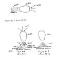
- FIG. 21A depicts a stationary jet engine operating vertically above, yet close to a horizontal surface
- FIG. 21B depicts the resultant pressure profile from a stationary jet engine operating vertically above, yet close to a horizontal surface
- FIG. 22A depicts the addition of a double shroud system to a vertically operating jet engine
- FIG. 22B shows a side view of the double shroud system
- FIG. 22C shows the resultant pressure distribution from the double shroud system
- FIG. 23 depicts a lifting platform with energy recovery.
- the present invention utilizes two lift systems.
- the first lift system pushes air from a propeller, fan or pump downwards and may also use downward directed gasses from a gas turbine or jet engine exhaust.
- Three basic configurations are shown in FIGS. 1A, 1 B and 1 C.
- the first system 100 depicted in FIG. 1A, has a propeller or fan 103 .
- Propeller or fan 103 is rotated by a motor 104 . This causes air 105 to flow into the device 100 , between outer shroud 106 and inner shroud 107 , through flow straightening vanes 108 , to finally be ejected downward as denoted by arrows 109 , at a speed V and density ⁇ .
- the second system, 101 utilizes a centrifugal pump comprising impeller 110 which is rotated by motor 111 .
- the input airflow flows through the vanes of the impeller 110 and flows between inner shroud 113 and outer shroud 114 and finally through flow straightening vanes 115 .
- the air 112 is then ejected downwards in accordance with arrows 116 , with specific V and ⁇ .
- the third system, 102 depicted in FIG. 1C, utilizes a gas turbine engine 117 . Jet engine 117 sucks air in 118 and ejects it at a much higher rate through the channel between inner shroud 119 and outer shroud 120 .
- vanes 200 are encased between outer shroud 201 and inner shroud 202 . In many cases concentric vanes may also be installed.
- FIGS. 1A, 1 B and 1 C The operation of all three variations of FIGS. 1A, 1 B and 1 C is to eject air or gas downwards.
- This action in taking still air from above the vehicle and ejecting it downwards causes an upward thrust, or lift, on the vehicle.
- this upward force is a result of the change of momentum of the air or gas.
- the thrust equals the volume of expelled gas times the gas density r times the gas speed V.
- foot-pound-second notation the result is in terms of foot pounds per second per second.
- the equivalent weight lifted is Mg, where M is the Mass supported and g the acceleration due to gravity.
- Static pressure is generated by deflecting the downward airflow from between the two shrouds outward to form a partial toroidal vortex.
- FIG. 3 shows a toroidal vortex. It is most commonly associated with a smoke ring and can be considered as a series of concentric circular air tubes nested one inside the other. The direction of airflow is shown by streamlines 300 . The pressure inside each tube is lower than the one in which it is nested. Thus there is a low pressure inside but atmospheric pressure outside. Using the momentum theory of fluid dynamics the pressure across any stream tube taken on the line AB, and radius R with air speed V is given by ⁇ V 2 /R where ⁇ is the localized pressure. Integrating the pressure differences across all the stream tubes determines the pressure at the center A.
- the lifting platform makes use of the pressure profile across a toroidal vortex.
- the pressure at the center is atmospheric and that on the outside is the internal static pressure of the lifting platform.
- the high pressure is only present for one quarter of a revolution; for the other three quarters the ambient pressure is atmospheric and so the vortex dissipates, there being no pressure difference between its inside and outside.
- the quarter vortex is sufficient to provide the source of static internal pressure.
- FIG. 4 shows the airflow 401 through a lifting platform 400 .
- Air passing vertically downward through the flow straightening vanes 402 via propeller 405 is deflected to the sides by the operating surface 403 and in doing so forms a partial toroidal vortex in region 404 with line AB corresponding to line AB in FIG. 3 .
- FIG. 5 shows the resultant pressure profile beneath lifting platform 400 and operating surface 403 .
- the increased pressure under the central area 501 provides direct lift.
- the increased pressure to the sides 502 under the flow straightening vanes 402 applies a back pressure to the fan, or propeller 405 , shown here, or to a centrifugal pump or jet engine, depending on the configuration.
- the combination of dynamic and static pressure to support a lifting platform is a novel element of the present invention.
- FIG. 6 shows a top view of a propeller or fan 600 surrounded by shroud 601 for which the ideal airflow goes downward, into the paper as it were, and is then deflected sideways by the operating surface as shown in vector A.
- the air spirals around according to line B, due to the propeller drag, and the effect may be even more pronounced when the power source is a centrifugal pump or jet engine.
- FIG. 7 such airflow forms a cylindrical vortex 700 below the outer shroud 601 .
- the effect causes “Vortex Attraction”, described in applicant's own co-pending application Ser. No.
- the operational height of this configuration is greater than that of a hovercraft, which relies solely on static pressure to provide lift.
- the power requirement is somewhat greater than that for a hovercraft with an efficient skirt at a height of a few inches, but far less than that for a helicopter hovering at the same height; the helicopter has no central static pressure lift zone.
- the lifting platform therefore, fills the gap between hovercraft and helicopter operation and as such is not described in prior art.
- One application of the hovering platform is operation over rough terrain that is inaccessible to hovercraft or road or track vehicles. An example of such operation is in the Arctic where hovercraft operation is limited by ice ridges in the ice pack.
- Another application is as an aerial crane, or lifting vehicle, that is able to operate over rough terrain but consumes less power than a helicopter and the terrain is unsuitable for a hovercraft.
- Such a vehicle would appear well suited to mine detection due to its ability to travel over rough surfaces without applying sufficient pressure to trigger a mine's detonator.
- Varying the proportions of the dynamic lift area, i.e. the area between the inner and outer shrouds, and the static lift area, i.e. that under the inner shroud, provides a variety of operating characteristics for different applications.
- FIG. 8 shows a ducted fan 800 operating close to a flat surface 801 .
- the ducted fan comprises a propellor 803 circumferentially surrounded by a the shroud 802 .
- the propeller blade tip vortex, A is restricted to the very tip of the blade and the magnitude depends on the depth of the shroud 802 .
- the stream lines A,B,C,D clearly show the cross section of the partial toroidal vortex set up by the ducted fan 800 .
- the pressure profile shown in FIG. 9, shows a fairly even pressure build up beneath the fan 800 due to air being deflected sideways by the flat surface 801 . This action, although it is not described as such, is due to the formation of a partial toroidal vortex.
- Such pressure increase called back pressure, improves the propeller efficiency by reducing the downwash angle and drag and bringing the resultant lift force closer to the vertical.
- the propeller pitch has to be set correctly to maximize the effect.
- the arrangement suffers, as in the earlier description, by air corkscrewing or spiraling downwards rather than moving vertically down.
- the back pressure is limited by the formation of a cylindrical vortex beneath the shroud 802 which reduces and may even eliminate the back pressure.
- vanes 1000 In order to make the ducted fan into an efficient lifting platform, when located close to the ground it must be fitted with flow straightening vanes 1000 as shown in FIG. 10 . Propeller 1001 and vanes 1000 are encased by shroud 1002 . If lateral movement is desired, vanes 1000 may be deflected from the vertical axis to generate a lateral component in the downward airflow. As a result of such deflection, static pressure is reduced by an amount equal to the cosine of the angle to the vertical while a horizontal force is produced which is proportional to the sine of the same angle.
- vanes 1000 should be deflected such that the angle of a vane 1000 corresponds to the angle of another vane 1000 across from it.
- some vanes 1000 on either side must be deflected by the same amount to provide a backward airstream.
- some vanes 1000 on either side must be deflected by the same amount to provide a forward airstream.
- For sideways thrust vanes 1000 on the front and back must be deflected by the same amount to generate a sideways airflow.
- Vanes 1000 may also be deflected in opposite directions in order to turn the apparatus, however, the amount of airflow deviation from the vertical is limited because such flow forms a cylindrical vortex that will decrease the static pressure.
- FIG. 1A shows the airflow around a ducted fan with flow vanes 1104 close to the ground, and in FIG. 11B, at altitude.
- the motor mounting 1101 provides a small area in the center for the static pressure to act.
- the first is due to the downward momentum of air providing lift as a reactionary force.
- the second is the outward deflection of the air into a partial toroidal vortex which provides a back pressure or ground effect that increases the lift and efficiency of the propeller, and the third is the static upward pressure against the engine mounting.
- flow-straightening vanes 1104 may be deflected accordingly if lateral movement is desired.
- FIG. 11B when in flight, there is no outward curving of the air flow 1103 close to the shroud 1002 .
- the lift in this case is produced solely by the rate of change of air momentum through the propeller.
- FIG. 12 shows the tip vortices 1201 generated by a propeller 1200 or helicopter rotor. They limit the amount of air blown downward at the tip and absorb power.
- a flying ducted fan is, therefore, fundamentally more efficient than a helicopter, and the efficiency is greatly enhanced when operating close to the ground because the partial toroidal vortex produced within the shroud is more intense, and the back pressure greater than the unshrouded rotor.
- the ducted fan is less suited to horizontal flight than a helicopter, it has a large side area, so it cannot replace a helicopter where fast travel is required.
- the ducted fan with flow straightening vanes is superior.
- the ducted fan configuration of FIG. 10 may be simply converted to a Vortex Attractor 1300 by swinging around the flow straightening vanes 1301 , as shown in FIG. 13, and feathering the propeller blades 1302 . Again, the blades are surrounded by shroud 1303 . In such a mode it will be attracted to a ceiling or other reasonably flat horizontal surface, and may be driven around on wheels (not shown). The operating sequence would be to fly up to the ceiling configured as in FIG. 10, rotate the flow vanes 1301 as in FIG. 13 and then feather the propeller blades 1302 . The power required to hold to the ceiling is approximately one tenth of the power required to fly. Applications for this mode include surveillance and inspection of difficult to access horizontal surfaces.
- FIG. 14 A typical prior art hovercraft 1400 is shown in FIG. 14 . It comprised of a deck 1401 surrounded by a flexible skirt 1402 . Air 1403 is blown in from the top via propeller 1405 to establish a high pressure zone within the skirt 1402 to lift the hovercraft 1400 upward.
- the skirt 1402 forms an imperfect seal to the operating surface 1404 . Any non-uniformities in the surface 1404 , such as stones in a road, or waves in water, allow air 1403 to escape under the skirt 1402 .
- the diagram shows that air 1403 blowing in from the top is deflected by the working surface 1404 and passes out horizontally under the skirt 1402 . In this case there is no surrounding toroidal vortex formation to form a pressure barrier to limit the air escape.
- the air 1501 is blown down a hollow skirt 1502 via blower 1503 .
- the operation is now similar to that of FIG. 1 in which a partial toroidal vortex 1506 is formed along the edge of the skirt 1502 to maintain a high pressure under the platform 1504 .
- the pressure automatically rises to that determined by the velocity and radius of curvature of the air 1501 as it changes its direction from vertical, in the air duct 1507 of the hollow skirt 1502 , to horizontal as it passes out sideways.
- the skirt 1502 must have vertical vanes (not shown) to prevent horizontal circulation unless lateral movement is desired.
- said vertical vanes may be deflected accordingly for this purpose. Blowing the air downward at the edge of the craft requires less power to maintain lifting pressure. In this case the majority of the lift is provided by the static pressure within the inner shroud and very little dynamic lift is generated. Hovercraft have been made with double skirts with air blowing down between them, although these do not seem to have found much commercial success.
- the arrangement of the present invention depicted in FIG. 15 differs in that it includes flow straightening vanes to maximize partial toroidal vortex formation and consequently the inner static pressure.
- a lifting platform 1600 is shown wherein the duct 1601 between the inner 1602 and outer 1603 shrouds may be curved as shown (with radius of curvature R) in order to inject the moving air 1604 at an angle under the platform 1605 .
- the flow would be as illustrated by streamline 1606 , having a velocity V.
- This is a technique commonly used in hovercraft and first patented by Christopher Cockerell in the 1960's, as a way to increase the pressure beneath the craft. When air is injected at an angle the air has to turn through a smaller angle to escape outward and the interior pressure is raised accordingly. There is a downside to doing this, however, for in curving the downward flowing air inward its momentum is changed.
- the resultant force F equals the rate of change of momentum of the air; it has a downward component that cancels some of the upward lift due to the pressure beneath the platform. In other words, the dynamic lift effect is reduced in order to maximize the static pressure.
- a hovercraft may be seen as a wholly static pressure device. Hovercraft are limited to operating a matter of inches above a ground or water surface. As such they represent one end point in the new lifting platform development; the point at which dynamic lift generation is too small to be relevant. It is curious that the fifty years of hovercraft design has ignored the dynamic lift generation that is fundamental to the new development and essential if a platform is to rise high off the ground.
- the system 1500 of FIG. 15 becomes a hovering platform within the boundaries of this description, when the relative areas between the inner and outer shrouds and the area beneath the inner shrouds are adjusted, in order to permit dynamic lift generation by the downward airflow to become a substantial part of the lifting force. Then, by increasing the power, the platform may be lifted sufficiently to clear obstacles. A conventional hovercraft, however, is unable to do this.
- the hovering platform of FIG. 15 is not best served with a propeller as the air mover.
- a propeller or fan does not operate well when passing a small amount of air into a high back pressure, the conditions for efficient lift generation with the platform operating close to a flat surface.
- a more efficient air mover under these conditions is the centrifugal blower of the type used in vacuum cleaners. It is common knowledge that blocking up a vacuum cleaner hose takes the load off the motor and allows it to speed up. This is because the circulating air within the blades adjusts to the output pressure, it prevents new air from moving in and does not waste power in air circulation around the blades. When the platform is close to the ground, and there is little air throughput, the centrifugal pump consumes little power.
- FIG. 17 shows an arrangement 1700 with a centrifugal air pump comprising spinning hub 1702 and blades 1703 attached thereto sitting within the outer shroud 1701 (shown cutaway).
- Incoming air follows streamline 1704 , wherein it enters from above and is blown sideways into the space between the inner 1705 and outer shroud 1701 and then downwards through flow straightening vanes 1706 .
- flow-straightening vanes 1706 may be deflected if lateral movement is desired.
- Impeller blades 1703 may also be deflected with similar results. It should be noted, however, that in this case the air pump impeller does not provide any lift.
- the propellers in the preceding figures all generate lift independently, and increasing amounts of lift as the platform approaches the flat surface and the back pressure increases. Lift is provided, however, as the horizontal airflow through the impeller blades 1703 turns downward between the inner shroud 1705 and outer shroud 1701 . This lift is equal to the rate of change of momentum of the air from horizontal to vertical.
- the centrifugal blower approach is very efficient when the platform is close to the working surface, the air throughput is low and the pressure below the central area is high.
- the lifting platform with a centrifugal air pump operates efficiently in the hovercraft realm, and also for rising above obstacles for which the centrifugal pump airflow is able to generate sufficient dynamic lift.
- FIG. 18 shows an expanded hub ducted fan 1800 comprising an extended lip 1801 on the outer shroud 1802 which acts as an airfoil to air 1806 flowing into the propeller blades 1803 and through flow straightening vanes 1809 .
- the device 1800 is optimally operated close to the horizontal surface 1808 .
- Propeller blades 1803 are mounted to hub 1804 , which is driven by motor 1805 .
- the resultant force, represented by vector 1807 due to air 1806 flowing into the outer edge of the propeller 1803 has a vertical component which aids in lifting the device 1800 .
- Such airfoil sectioned lips have been commonly applied to ducted fans, but never before to a lifting platform application.
- FIG. 11B When the lifting platform is flying, or set high above a flat surface the airflow is as shown in FIG. 11B with air exiting vertically downwards, energy cannot be gained from this outflow.
- FIG. 11A when the platform is operating close to a flat surface, as in FIG. 11A, air passing through the blade tip region leaves the outer shroud with a slightly upward angle and so energy may be retrieved by a device located above the level of the bottom of the shroud. This effect is enhanced when the outer shroud has an upper lip as in FIG. 18 .
- venturi action draws air down the outside of the shroud to exit with an upward tilt.
- the device 1900 of FIG. 19 builds upon this idea by adding an additional annular wing 1901 having wing section 1902 .
- Placement of this additional annular wing 1901 is such that is derives lift from airflow that is above the level of the bottom of the shroud 1903 .
- Streamlines 1904 illustrate the airflow.
- the overall ducted fan mechanism 1905 is identical to that of FIG. 18, with the addition of annular wing 1901 .
- Aircraft jet engines are designed to operate efficiently when moving horizontally at flying speed. They may be designed to sacrifice some flying speed in order to generate high thrust while stationary on the ground. There are difficulties though when a jet engine operates vertically close to the ground blowing gas directly downwards for vertical take off.
- the present invention does not propose any alteration of the engines characteristics, rather they intend to show an approach to increase the available thrust when close to the ground and to produce a characteristic that has increasing thrust with decreasing distance to the ground.
- a stationary, horizontally mounted jet engine 2000 is illustrated.
- Such an engine 2000 develops thrust by intake of a low speed flow of gas 2001 and rejecting a high speed flow of gas 2002 .
- Such a situation lends itself to analysis by momentum theory.
- Momentum theory shows that the thrust generated by engine 2000 to be equal to the rate of change of momentum of the gases 2001 to 2002 .
- the thrust With the engine 2000 sitting in sill air, the thrust equals the mass of air ejected 2002 per second multiplied by the speed of the gas 2002 .
- This situation is analogous when the engine 2000 operates vertically, such as in FIG. 21A, with the intake of gas 2101 at the top.
- the thrust equals the mass of gas ejected 2100 per second multiplied by the speed V of the gas 2100 .
- this rate of change of momentum is made equal to the mass of the aircraft multiplied by the acceleration due to gravity (9.8 m/s 2 or 32.17 ft/s 2 ).
- the ejected gas 2100 is prevented from continuing in a straight fashion by the ground 2102 , and instead, has to curve outward to the sides.
- Such a curvature leads to the establishment of a high pressure area beneath the engine 2000 which can be calculated knowing the speed V and radius of curvature R of each stream tube 2104 .
- the pressure difference across the stream tube is ⁇ V 2 /R where “ ⁇ ” is the gas density. Integrating all stream tubes leads to FIG. 21 B.
- beneath engine 2000 is the representative pressure profile 2105 . Note the maximum at the center, and drastic reduction at the edges.
- the back pressure is an advantage to a helicopter for which the blade lift is increased and drag decreased. Operation close to the ground is stable because the lift increases as the height decreases. Such is not the case for a jet engine because the back pressure upsets its efficiency.
- the blades on the power turbine are set for efficient operation with high gas flow at low pressure. They are not designed to deliver gas into a high pressure. Making things more difficult, turbines do not have variable pitch blades.
- the present invention comprises a new approach to a lifting platform in which the central area of high pressure, as in FIG. 21B, is extended to provide lift while the pressure is maintained by high speed air flow around the periphery.
- FIGS. 22A, 22 B and 22 C show a possible extension of the technique to enhance a jet engine thrust when close to the ground.
- the basic arrangement 2200 in FIG. 22A has a double shroud system comprising outer shroud 2201 and inner shroud 2202 to spread the output gas 2203 from jet engine 2000 over an inner shroud 2202 and then vertically downwards.
- An outer shroud 2201 completes the gas duct.
- Vanes are fitted between the inner 2202 and outer 2201 shrouds to ensure that the gas 2203 leaving the system 2200 travels vertically downwards. These vanes may also be steerable for control purposes, i.e., lateral motion..
- the pressure in the inner “lift area” 2205 is determined by integrating ⁇ V 2 /R for all the stream tubes 2206 turning from vertical to horizontal.
- the pressure at the outside edges of the inner shroud 2202 is maintained across the central area.
- the ground effect lets you have it for free.
- the air curving out from between the inner and outer shrouds forms a partial toroidal vortex.
- the pressure derivations are as for a complete toroidal vortex with ambient pressure in the core. This system is therefore termed Vortex Lift.
- the bulk of the lift is derived from the high pressure area 2207 beneath the inner shroud 2202 .
- the system also allows the gas leaving the jet engine to expand across the top of the inner shroud 2202 thus reducing the back pressure acting on it and increasing its efficiency. Therefore, the system design balances engine characteristics against pressure in the central area.
- the central pressure is inversely proportional to the distance from the ground 2204 . This means that the lift increases with proximity to the ground, a stable behavior.
- This lift system 2200 only works when the aircraft is close to the ground and has no effect at altitude. Whereas the jet ports on the Harrier swivel when changing from vertical to horizontal propulsion, the shrouds in this system would be a huge drag when swiveled for forward thrust. It may be that a compromising system can be made retractable.
- Another approach is to use the entire central fuselage-wing root area as the central lift area and direct high speed gases through a continuous series of nozzles around this area. As the central area lift effect is still considerable when the height above the ground equals the outer ring diameter such an arrangement could provide lift enhancement to a height of 10 to 15 feet.
- FIG. 23 depicts a cut-away view of a lifting platform 2300 in which the toroidal vortex (which was incomplete in prior embodiments) that sustains the lifting platform, is made complete.
- the toroidal vortex is formed around a “donut” 2302 in much the same way as the inventor's previously described toroidal vortex attractors. The only distinction is that, in this case, the air flow direction is reversed—the air goes downward at the center of the donut and upwards around the outside within an outer shroud 2304 .
- the outer shroud 2304 is extended to wrap around the donut 2302 .
- the internal pressure is not necessarily provided by the vortex, but by an optional additional fan and motor 2306 . Fan and motor 2306 can be used to develop the required pressure within and under the inner shroud 2311 .
- the airflow is effected by motor 2305 coupled to vortex fan blades 2301 .
- the air moving downwards with a velocity V (shown by streamline 2309 ) at the center of the donut 2302 is pushed sideways at the bottom and turns sideways with a radius of curvature R 1 (shown by 2307 ).
- the pressure differential between the central area 2310 and the donut 2302 is thus V 2 /R 1 , in which is the air density, V is the air speed 2309 around the donut 2302 , and R 1 is the radius of the air curving outward.
- the air moving sideways and outward is pulled up into the duct between the donut 2302 and the outer shroud 2304 . It is also pushed up by atmospheric pressure.
- the pressure difference between atmospheric and the pressure around the donut 2302 is V 2 /R 2 , in which is the air density, V is the air speed 2309 around the donut 2302 , and R 2 is the radius of curvature 2308 between the donut 2302 and the atmosphere.
- V the air density
- R 2 the radius of curvature 2308 between the donut 2302 and the atmosphere.
- the airflow passing downwards between the inside of the donut 2302 and the inner shroud 2311 has to be made vertical by inserting flow straightening vanes (not shown) in order to prevent cylindrical vortex effects that tend to throw air out sideways.
- the air continuously cycles around the donut 2302 so that the prime function of the motor 2305 and vortex fan blades 2301 is to replace energy losses due to friction. Recycling the air minimizes the disturbance to the surroundings due to laterally ejected air of prior lifting platforms.
- the optional pressure fan 2306 are contemplated to provide independent control of the central pressure and vortex airspeed. The pressure fan 2306 is not essential to the lifting function.
Landscapes
- Engineering & Computer Science (AREA)
- Aviation & Aerospace Engineering (AREA)
- Mechanical Engineering (AREA)
- Physics & Mathematics (AREA)
- Fluid Mechanics (AREA)
- General Engineering & Computer Science (AREA)
- Toys (AREA)
Abstract
Description
Claims (17)
Priority Applications (2)
| Application Number | Priority Date | Filing Date | Title |
|---|---|---|---|
| US09/871,597 US6464459B2 (en) | 1999-05-21 | 2001-05-31 | Lifting platform with energy recovery |
| US09/895,961 US6623352B2 (en) | 1999-05-21 | 2001-06-29 | Vortex air barrier |
Applications Claiming Priority (3)
| Application Number | Priority Date | Filing Date | Title |
|---|---|---|---|
| US09/316,318 US6595753B1 (en) | 1999-05-21 | 1999-05-21 | Vortex attractor |
| US09/728,602 US6616094B2 (en) | 1999-05-21 | 2000-12-01 | Lifting platform |
| US09/871,597 US6464459B2 (en) | 1999-05-21 | 2001-05-31 | Lifting platform with energy recovery |
Related Parent Applications (1)
| Application Number | Title | Priority Date | Filing Date |
|---|---|---|---|
| US09/728,602 Continuation-In-Part US6616094B2 (en) | 1999-05-21 | 2000-12-01 | Lifting platform |
Related Child Applications (1)
| Application Number | Title | Priority Date | Filing Date |
|---|---|---|---|
| US09/895,961 Continuation-In-Part US6623352B2 (en) | 1999-05-21 | 2001-06-29 | Vortex air barrier |
Publications (2)
| Publication Number | Publication Date |
|---|---|
| US20020047071A1 US20020047071A1 (en) | 2002-04-25 |
| US6464459B2 true US6464459B2 (en) | 2002-10-15 |
Family
ID=27405858
Family Applications (1)
| Application Number | Title | Priority Date | Filing Date |
|---|---|---|---|
| US09/871,597 Expired - Fee Related US6464459B2 (en) | 1999-05-21 | 2001-05-31 | Lifting platform with energy recovery |
Country Status (1)
| Country | Link |
|---|---|
| US (1) | US6464459B2 (en) |
Cited By (46)
| Publication number | Priority date | Publication date | Assignee | Title |
|---|---|---|---|---|
| US20040234396A1 (en) * | 2000-06-09 | 2004-11-25 | Imrich Horvath | Method of generating electrical energy and apparatus for carrying out the method |
| US20050161269A1 (en) * | 2004-01-23 | 2005-07-28 | Bahram Khalighi | Virtual airdam and method for a vehicle |
| WO2005091740A3 (en) * | 2003-10-04 | 2005-12-22 | Wang Hui | New flying / lifting mechanisms |
| WO2005081678A3 (en) * | 2003-09-01 | 2006-01-12 | Hui Wang | New flying/lifting mechanism used in gas or liquid environment |
| US20070017722A1 (en) * | 2003-02-07 | 2007-01-25 | St Louis Daniel M | Levitating platform |
| US20070062543A1 (en) * | 2005-09-20 | 2007-03-22 | Bastian Family Holdings, Inc. | Stabilizing power source for a vehicle |
| US20070258188A1 (en) * | 2006-05-02 | 2007-11-08 | Advanced Desalination Inc. | Configurable power tank for power delivery and storage |
| US7318374B2 (en) | 2003-01-21 | 2008-01-15 | Victor Guerrero | Wire cloth coffee filtering systems |
| US7461587B2 (en) | 2004-01-21 | 2008-12-09 | Victor Guerrero | Beverage container with wire cloth filter |
| US20090236470A1 (en) * | 2008-03-19 | 2009-09-24 | Honeywell International, Inc. | Launch and capture systems for vertical take-off and landing (vtol) vehicles |
| US20100014977A1 (en) * | 2008-07-15 | 2010-01-21 | Shattuck Colman D | Variable pitch aft propeller vane system |
| US20100064718A1 (en) * | 2008-09-15 | 2010-03-18 | Mike Blomquist | Energy efficient modular cooling system |
| US20100129215A1 (en) * | 2008-11-21 | 2010-05-27 | Preus Robert W | System for providing dynamic pitch control in a wind turbine |
| US7786611B1 (en) * | 2008-06-12 | 2010-08-31 | Thomas Manaugh | System and method for generating wind power from a vertical structure |
| US7906068B2 (en) | 2003-07-14 | 2011-03-15 | Cooper Paul V | Support post system for molten metal pump |
| US8075837B2 (en) | 2003-07-14 | 2011-12-13 | Cooper Paul V | Pump with rotating inlet |
| US8135503B2 (en) * | 2010-04-27 | 2012-03-13 | Honeywell International Inc. | Ground proximity sensor |
| US20120329378A1 (en) * | 2006-04-27 | 2012-12-27 | Eaton Corporation | Assembly for Extracting Heat from a Housing for Electronic Equipment |
| US8461712B1 (en) * | 2012-06-04 | 2013-06-11 | Victor Lyatkher | Power generating system |
| US8529828B2 (en) | 2002-07-12 | 2013-09-10 | Paul V. Cooper | Molten metal pump components |
| US9034244B2 (en) | 2002-07-12 | 2015-05-19 | Paul V. Cooper | Gas-transfer foot |
| US9080577B2 (en) | 2009-08-07 | 2015-07-14 | Paul V. Cooper | Shaft and post tensioning device |
| US9108244B2 (en) | 2009-09-09 | 2015-08-18 | Paul V. Cooper | Immersion heater for molten metal |
| US9205490B2 (en) | 2007-06-21 | 2015-12-08 | Molten Metal Equipment Innovations, Llc | Transfer well system and method for making same |
| US9328615B2 (en) | 2009-08-07 | 2016-05-03 | Molten Metal Equipment Innovations, Llc | Rotary degassers and components therefor |
| US9383140B2 (en) | 2007-06-21 | 2016-07-05 | Molten Metal Equipment Innovations, Llc | Transferring molten metal from one structure to another |
| US9410744B2 (en) | 2010-05-12 | 2016-08-09 | Molten Metal Equipment Innovations, Llc | Vessel transfer insert and system |
| US9869190B2 (en) | 2014-05-30 | 2018-01-16 | General Electric Company | Variable-pitch rotor with remote counterweights |
| US9903383B2 (en) | 2013-03-13 | 2018-02-27 | Molten Metal Equipment Innovations, Llc | Molten metal rotor with hardened top |
| CN108454606A (en) * | 2018-04-12 | 2018-08-28 | 华南智能机器人创新研究院 | Side wall type hovercraft |
| US10072510B2 (en) | 2014-11-21 | 2018-09-11 | General Electric Company | Variable pitch fan for gas turbine engine and method of assembling the same |
| US10100653B2 (en) | 2015-10-08 | 2018-10-16 | General Electric Company | Variable pitch fan blade retention system |
| US10428821B2 (en) | 2009-08-07 | 2019-10-01 | Molten Metal Equipment Innovations, Llc | Quick submergence molten metal pump |
| US10604255B2 (en) | 2017-06-03 | 2020-03-31 | Dennis S. Lee | Lifting system machine with methods for circulating working fluid |
| US10669023B2 (en) | 2016-02-19 | 2020-06-02 | Raytheon Company | Tactical aerial platform |
| US10897858B2 (en) | 2017-11-30 | 2021-01-26 | Tti (Macao Commercial Offshore) Limited | Blower/mulcher |
| US20230083741A1 (en) * | 2012-04-12 | 2023-03-16 | Supercell Oy | System and method for controlling technical processes |
| US11674435B2 (en) | 2021-06-29 | 2023-06-13 | General Electric Company | Levered counterweight feathering system |
| US11795964B2 (en) | 2021-07-16 | 2023-10-24 | General Electric Company | Levered counterweight feathering system |
| US11809794B2 (en) | 2019-10-28 | 2023-11-07 | Corcat, Inc. | System and method for simulating turbulence |
| US11987402B2 (en) | 2021-03-29 | 2024-05-21 | The Boeing Company | Vertical air vehicle takeoff and landing stabilization apparatuses, systems, and methods |
| US11993409B2 (en) | 2021-03-29 | 2024-05-28 | The Boeing Company | Vertical air vehicle takeoff and landing stabilization apparatuses, systems, and methods |
| US12116143B2 (en) | 2021-03-29 | 2024-10-15 | The Boeing Company | Vertical air vehicle takeoff and landing stabilization apparatuses, systems, and methods |
| WO2025014192A1 (en) * | 2023-07-11 | 2025-01-16 | (주)창인에이비에이션 | Lifting apparatus for aerial vehicle |
| US12352274B2 (en) | 2022-03-21 | 2025-07-08 | Milwaukee Electric Tool Corporation | Axial blower |
| US12385494B2 (en) | 2021-10-11 | 2025-08-12 | Milwaukee Electric Tool Corporation | Fan for handheld blower |
Families Citing this family (29)
| Publication number | Priority date | Publication date | Assignee | Title |
|---|---|---|---|---|
| US7826318B2 (en) * | 2004-04-27 | 2010-11-02 | Apple Inc. | Method and system for allowing a media player to transfer digital audio to an accessory |
| US8413932B2 (en) * | 2010-04-10 | 2013-04-09 | Aerofex, Inc. | Peripheral control ejector |
| US8257019B2 (en) * | 2006-12-21 | 2012-09-04 | Green Energy Technologies, Llc | Shrouded wind turbine system with yaw control |
| US9194362B2 (en) | 2006-12-21 | 2015-11-24 | Green Energy Technologies, Llc | Wind turbine shroud and wind turbine system using the shroud |
| US8262338B2 (en) | 2007-01-11 | 2012-09-11 | Cassidy Joe C | Vertical axis dual vortex downwind inward flow impulse wind turbine |
| US8596570B1 (en) * | 2011-02-22 | 2013-12-03 | David Carambat | Aircraft vehicle centrifugal fan apparatus |
| WO2013105926A1 (en) * | 2011-03-22 | 2013-07-18 | Aerovironment Inc. | Invertible aircraft |
| JP6108077B2 (en) * | 2013-01-29 | 2017-04-05 | 株式会社Ihi | Vertical take-off and landing aircraft |
| ITRM20130473A1 (en) * | 2013-08-12 | 2013-11-11 | Unit 1 Srl | CONVERTIPLATE WITH NEW TECHNICAL AND AERODYNAMIC SOLUTIONS THAT CAN MAKE THE MEANS ALSO IN SAFE AND ULTRA-LIGHT AIRCRAFT SOLUTIONS |
| US9278778B2 (en) * | 2014-04-21 | 2016-03-08 | Oria Collapsibles, Llc | Multi-functional pallet with locating support structure and buoyancy characteristics and including RFID-GPS tracking and light (sound) locating features in combination with magnetic stackability during non-use |
| US9802700B1 (en) * | 2014-11-13 | 2017-10-31 | Jonathan M. Essary | VTOL rotary aircraft and method of use |
| US10766615B1 (en) * | 2015-03-10 | 2020-09-08 | Lindsay O'Brien Quarrie | Hover airlift logistics operations guided expeditionary autonomous scalable and modular VTOL platform |
| CN106103274B (en) * | 2015-07-02 | 2017-11-14 | 深圳市大疆创新科技有限公司 | UAV, its control system and method, and UAV landing control method |
| US10155507B2 (en) | 2016-01-28 | 2018-12-18 | Vescovi Innovations, LLC | Compressed gas levitation device |
| FR3056555B1 (en) * | 2016-09-29 | 2018-12-07 | Safran Helicopter Engines | HYBRID PROPULSIVE SYSTEM FOR MULTIROTOR ROTARY FLYWELL AIRCRAFT COMPRISING IMPROVED DC / AC CONVERSION MEANS |
| CN107298166A (en) * | 2017-07-31 | 2017-10-27 | 张家港致盈电子技术有限公司 | Dish-shaped multifunction aircraft |
| WO2019033080A1 (en) | 2017-08-10 | 2019-02-14 | Neiser Paul | Apparatus and method for fluid manipulation |
| US12270301B2 (en) | 2017-08-10 | 2025-04-08 | Paul NEISER | System and method for fluid manipulation |
| US12570391B2 (en) | 2017-08-10 | 2026-03-10 | Paul NEISER | Apparatus and method for fluid manipulation |
| US11378061B2 (en) * | 2018-05-23 | 2022-07-05 | Raytheon Technologies Corporation | Electric rotor dynamics damping |
| JP7329057B2 (en) * | 2018-10-22 | 2023-08-17 | ネイサー、ポール | Systems and methods for fluid manipulation |
| JP7269722B2 (en) * | 2018-12-13 | 2023-05-09 | 三菱重工業株式会社 | Motor-integrated fluid machine and vertical take-off and landing aircraft |
| KR102716432B1 (en) * | 2019-08-12 | 2024-10-11 | 한화에어로스페이스 주식회사 | Lift device for VTOL |
| US20210061248A1 (en) * | 2019-08-19 | 2021-03-04 | Mark T. Holtzapple | Enhanced-Thrust Lift and Propulsion Systems |
| US12434682B1 (en) * | 2019-11-26 | 2025-10-07 | Owen Richard Wiseman | Hover drone system |
| US12022634B2 (en) * | 2020-10-15 | 2024-06-25 | Nvidia Corporation | Adjustable fan for datacenter cooling systems |
| GB2603754B (en) * | 2021-02-01 | 2023-05-10 | Verderg Ltd | A power generation and/or storage apparatus |
| US12105533B1 (en) * | 2023-05-08 | 2024-10-01 | Archer Aviation Inc. | Powered lift enable and disable switch |
| CN116533696B (en) * | 2023-05-10 | 2026-02-17 | 南京航空航天大学 | Cross-medium aircraft power device and working method thereof |
Citations (11)
| Publication number | Priority date | Publication date | Assignee | Title |
|---|---|---|---|---|
| US3150732A (en) * | 1960-07-01 | 1964-09-29 | Curtiss Wright Corp | Propulsion system for air borne ground effect vehicles |
| US3162260A (en) * | 1959-06-10 | 1964-12-22 | Hovercraft Dev Ltd | Vehicle for travelling over land and/or water |
| US3168155A (en) * | 1960-01-19 | 1965-02-02 | Hovercraft Dev Ltd | Vehicles for travelling over land and/or water |
| US3194333A (en) * | 1960-04-05 | 1965-07-13 | Hovercraft Dev Ltd | Ground effect machines with supply and recovery ports in a common duct |
| US3249165A (en) * | 1961-09-06 | 1966-05-03 | Jr Harvey R Chaplin | Simplified nozzle control for ground effect machines |
| US3262510A (en) * | 1962-06-04 | 1966-07-26 | Alphons J Froehler | Air cushion vehicle with lift, turn, and brake controls |
| US3279553A (en) * | 1962-03-23 | 1966-10-18 | Anibal A Tinajero | Pitch and roll control for ground effect machines |
| US3285357A (en) * | 1960-09-29 | 1966-11-15 | Fred Starobin A | Air cushion vehicles with maneuvering and forward propulsion controls |
| US3288235A (en) * | 1962-11-15 | 1966-11-29 | Westland Aircraft Ltd | Control system for ground effect vehicles |
| US3306389A (en) * | 1962-03-23 | 1967-02-28 | Anibal A Tinajero | Pitch and roll control for ground effect machines |
| US3363716A (en) * | 1955-12-12 | 1968-01-16 | Hovercraft Dev Ltd | Vehicles for travelling over land and/or water |
-
2001
- 2001-05-31 US US09/871,597 patent/US6464459B2/en not_active Expired - Fee Related
Patent Citations (11)
| Publication number | Priority date | Publication date | Assignee | Title |
|---|---|---|---|---|
| US3363716A (en) * | 1955-12-12 | 1968-01-16 | Hovercraft Dev Ltd | Vehicles for travelling over land and/or water |
| US3162260A (en) * | 1959-06-10 | 1964-12-22 | Hovercraft Dev Ltd | Vehicle for travelling over land and/or water |
| US3168155A (en) * | 1960-01-19 | 1965-02-02 | Hovercraft Dev Ltd | Vehicles for travelling over land and/or water |
| US3194333A (en) * | 1960-04-05 | 1965-07-13 | Hovercraft Dev Ltd | Ground effect machines with supply and recovery ports in a common duct |
| US3150732A (en) * | 1960-07-01 | 1964-09-29 | Curtiss Wright Corp | Propulsion system for air borne ground effect vehicles |
| US3285357A (en) * | 1960-09-29 | 1966-11-15 | Fred Starobin A | Air cushion vehicles with maneuvering and forward propulsion controls |
| US3249165A (en) * | 1961-09-06 | 1966-05-03 | Jr Harvey R Chaplin | Simplified nozzle control for ground effect machines |
| US3279553A (en) * | 1962-03-23 | 1966-10-18 | Anibal A Tinajero | Pitch and roll control for ground effect machines |
| US3306389A (en) * | 1962-03-23 | 1967-02-28 | Anibal A Tinajero | Pitch and roll control for ground effect machines |
| US3262510A (en) * | 1962-06-04 | 1966-07-26 | Alphons J Froehler | Air cushion vehicle with lift, turn, and brake controls |
| US3288235A (en) * | 1962-11-15 | 1966-11-29 | Westland Aircraft Ltd | Control system for ground effect vehicles |
Cited By (63)
| Publication number | Priority date | Publication date | Assignee | Title |
|---|---|---|---|---|
| US20040234396A1 (en) * | 2000-06-09 | 2004-11-25 | Imrich Horvath | Method of generating electrical energy and apparatus for carrying out the method |
| US9034244B2 (en) | 2002-07-12 | 2015-05-19 | Paul V. Cooper | Gas-transfer foot |
| US8529828B2 (en) | 2002-07-12 | 2013-09-10 | Paul V. Cooper | Molten metal pump components |
| US7318374B2 (en) | 2003-01-21 | 2008-01-15 | Victor Guerrero | Wire cloth coffee filtering systems |
| US20070017722A1 (en) * | 2003-02-07 | 2007-01-25 | St Louis Daniel M | Levitating platform |
| US7581608B2 (en) * | 2003-02-07 | 2009-09-01 | St Louis Daniel Mark | Levitating platform |
| US7906068B2 (en) | 2003-07-14 | 2011-03-15 | Cooper Paul V | Support post system for molten metal pump |
| US8075837B2 (en) | 2003-07-14 | 2011-12-13 | Cooper Paul V | Pump with rotating inlet |
| WO2005081678A3 (en) * | 2003-09-01 | 2006-01-12 | Hui Wang | New flying/lifting mechanism used in gas or liquid environment |
| WO2005091740A3 (en) * | 2003-10-04 | 2005-12-22 | Wang Hui | New flying / lifting mechanisms |
| US7461587B2 (en) | 2004-01-21 | 2008-12-09 | Victor Guerrero | Beverage container with wire cloth filter |
| US7055638B2 (en) * | 2004-01-23 | 2006-06-06 | General Motors Corporation | Virtual airdam and method for a vehicle |
| US20050161269A1 (en) * | 2004-01-23 | 2005-07-28 | Bahram Khalighi | Virtual airdam and method for a vehicle |
| US8648509B2 (en) | 2005-09-20 | 2014-02-11 | II William Allen Bastian | Stabilizing power source for a vehicle |
| US20070062543A1 (en) * | 2005-09-20 | 2007-03-22 | Bastian Family Holdings, Inc. | Stabilizing power source for a vehicle |
| US20100116924A1 (en) * | 2005-09-20 | 2010-05-13 | Bastian Family Holdings, Inc. | Stabilizing power source for a vehicle |
| US7825554B2 (en) | 2005-09-20 | 2010-11-02 | Bastian Family Holdings, Inc. | Stabilizing power source for a vehicle |
| US20120329378A1 (en) * | 2006-04-27 | 2012-12-27 | Eaton Corporation | Assembly for Extracting Heat from a Housing for Electronic Equipment |
| US10588245B2 (en) * | 2006-04-27 | 2020-03-10 | Eaton Intelligent Power Limited | Assembly for extracting heat from a housing for electronic equipment |
| US20070258188A1 (en) * | 2006-05-02 | 2007-11-08 | Advanced Desalination Inc. | Configurable power tank for power delivery and storage |
| US7696729B2 (en) | 2006-05-02 | 2010-04-13 | Advanced Desalination Inc. | Configurable power tank |
| US9383140B2 (en) | 2007-06-21 | 2016-07-05 | Molten Metal Equipment Innovations, Llc | Transferring molten metal from one structure to another |
| US9205490B2 (en) | 2007-06-21 | 2015-12-08 | Molten Metal Equipment Innovations, Llc | Transfer well system and method for making same |
| US8162256B2 (en) | 2008-03-19 | 2012-04-24 | Honeywell International Inc. | Launch and capture systems for vertical take-off and landing (VTOL) vehicles |
| US20090236470A1 (en) * | 2008-03-19 | 2009-09-24 | Honeywell International, Inc. | Launch and capture systems for vertical take-off and landing (vtol) vehicles |
| US7786611B1 (en) * | 2008-06-12 | 2010-08-31 | Thomas Manaugh | System and method for generating wind power from a vertical structure |
| US20100014977A1 (en) * | 2008-07-15 | 2010-01-21 | Shattuck Colman D | Variable pitch aft propeller vane system |
| US7775062B2 (en) * | 2008-09-15 | 2010-08-17 | Mike Blomquist | Modular cooling system |
| US20100064718A1 (en) * | 2008-09-15 | 2010-03-18 | Mike Blomquist | Energy efficient modular cooling system |
| US20100129215A1 (en) * | 2008-11-21 | 2010-05-27 | Preus Robert W | System for providing dynamic pitch control in a wind turbine |
| US8573937B2 (en) | 2008-11-21 | 2013-11-05 | Xzeres Corp. | System for providing dynamic pitch control in a wind turbine |
| US9080577B2 (en) | 2009-08-07 | 2015-07-14 | Paul V. Cooper | Shaft and post tensioning device |
| US9328615B2 (en) | 2009-08-07 | 2016-05-03 | Molten Metal Equipment Innovations, Llc | Rotary degassers and components therefor |
| US10428821B2 (en) | 2009-08-07 | 2019-10-01 | Molten Metal Equipment Innovations, Llc | Quick submergence molten metal pump |
| US9108244B2 (en) | 2009-09-09 | 2015-08-18 | Paul V. Cooper | Immersion heater for molten metal |
| US8135503B2 (en) * | 2010-04-27 | 2012-03-13 | Honeywell International Inc. | Ground proximity sensor |
| US9410744B2 (en) | 2010-05-12 | 2016-08-09 | Molten Metal Equipment Innovations, Llc | Vessel transfer insert and system |
| US11771988B2 (en) * | 2012-04-12 | 2023-10-03 | Supercell Oy | System and method for controlling technical processes |
| US20230083741A1 (en) * | 2012-04-12 | 2023-03-16 | Supercell Oy | System and method for controlling technical processes |
| US8461712B1 (en) * | 2012-06-04 | 2013-06-11 | Victor Lyatkher | Power generating system |
| US9903383B2 (en) | 2013-03-13 | 2018-02-27 | Molten Metal Equipment Innovations, Llc | Molten metal rotor with hardened top |
| US9869190B2 (en) | 2014-05-30 | 2018-01-16 | General Electric Company | Variable-pitch rotor with remote counterweights |
| US10072510B2 (en) | 2014-11-21 | 2018-09-11 | General Electric Company | Variable pitch fan for gas turbine engine and method of assembling the same |
| US10100653B2 (en) | 2015-10-08 | 2018-10-16 | General Electric Company | Variable pitch fan blade retention system |
| US10669023B2 (en) | 2016-02-19 | 2020-06-02 | Raytheon Company | Tactical aerial platform |
| US10604255B2 (en) | 2017-06-03 | 2020-03-31 | Dennis S. Lee | Lifting system machine with methods for circulating working fluid |
| US10897858B2 (en) | 2017-11-30 | 2021-01-26 | Tti (Macao Commercial Offshore) Limited | Blower/mulcher |
| CN108454606A (en) * | 2018-04-12 | 2018-08-28 | 华南智能机器人创新研究院 | Side wall type hovercraft |
| US11809794B2 (en) | 2019-10-28 | 2023-11-07 | Corcat, Inc. | System and method for simulating turbulence |
| US12116143B2 (en) | 2021-03-29 | 2024-10-15 | The Boeing Company | Vertical air vehicle takeoff and landing stabilization apparatuses, systems, and methods |
| US12371202B2 (en) | 2021-03-29 | 2025-07-29 | The Boeing Company | Vertical air vehicle takeoff and landing stabilization apparatuses, systems, and methods |
| US11987402B2 (en) | 2021-03-29 | 2024-05-21 | The Boeing Company | Vertical air vehicle takeoff and landing stabilization apparatuses, systems, and methods |
| US11993409B2 (en) | 2021-03-29 | 2024-05-28 | The Boeing Company | Vertical air vehicle takeoff and landing stabilization apparatuses, systems, and methods |
| US12479610B2 (en) | 2021-03-29 | 2025-11-25 | The Boeing Company | Vertical air vehicle takeoff and landing stabilization apparatuses, systems, and methods |
| US12420962B2 (en) | 2021-03-29 | 2025-09-23 | The Boeing Company | Vertical air vehicle takeoff and landing stabilization apparatuses, systems, and methods |
| US12371203B2 (en) | 2021-03-29 | 2025-07-29 | The Boeing Company | Vertical air vehicle takeoff and landing stabilization apparatuses, systems, and methods |
| US11674435B2 (en) | 2021-06-29 | 2023-06-13 | General Electric Company | Levered counterweight feathering system |
| US12180886B2 (en) | 2021-06-29 | 2024-12-31 | General Electric Company | Levered counterweight feathering system |
| US11795964B2 (en) | 2021-07-16 | 2023-10-24 | General Electric Company | Levered counterweight feathering system |
| US12385494B2 (en) | 2021-10-11 | 2025-08-12 | Milwaukee Electric Tool Corporation | Fan for handheld blower |
| US12352274B2 (en) | 2022-03-21 | 2025-07-08 | Milwaukee Electric Tool Corporation | Axial blower |
| KR20250009793A (en) * | 2023-07-11 | 2025-01-20 | (주)창인에이비에이션 | Lift device for Aircraft |
| WO2025014192A1 (en) * | 2023-07-11 | 2025-01-16 | (주)창인에이비에이션 | Lifting apparatus for aerial vehicle |
Also Published As
| Publication number | Publication date |
|---|---|
| US20020047071A1 (en) | 2002-04-25 |
Similar Documents
| Publication | Publication Date | Title |
|---|---|---|
| US6464459B2 (en) | Lifting platform with energy recovery | |
| US6616094B2 (en) | Lifting platform | |
| US6974106B2 (en) | V/STOL biplane | |
| US10967964B2 (en) | Air wheel rotor, a gyro stabilized aircraft and a wind-driven power generator using the air wheel rotor, and a stationary launching device | |
| US11878805B2 (en) | Efficient low-noise aircraft propulsion system | |
| EP0661206B1 (en) | An unmanned vertical take-off and landing, horizontal cruise, air vehicle | |
| US5039031A (en) | Turbocraft | |
| US5149012A (en) | Turbocraft | |
| RU2538737C9 (en) | Rotor "air wheel", gyrostabilised aircraft and wind-driven electric plant using rotor "air wheel", surface/deck devices for their start-up | |
| US20160144956A1 (en) | System and method for improving transition lift-fan performance | |
| US20120111994A1 (en) | Cross-flow fan propulsion system | |
| US6234422B1 (en) | Uniblade air rotor and flight and covercraft vehicles with its | |
| CN110963035A (en) | Personal aircraft with compressed air as power source and operation method thereof | |
| EP1592594A2 (en) | Levitating platform | |
| WO2018059244A1 (en) | Aircraft | |
| CN102120491A (en) | Upper-surface circulating jet fixed-wing helicopter | |
| CN206155777U (en) | Aircraft | |
| EP1273513A2 (en) | Propulsion system for supersonic aircraft | |
| CN1377790A (en) | Flapping-wing flying water automobile | |
| US20060032972A1 (en) | Vertical lift envelope | |
| US3215366A (en) | Rotorcraft | |
| CN211308973U (en) | Personal aircraft with compressed air as power source | |
| CN1081984A (en) | Flying saucer | |
| JPS61501766A (en) | Combined aircraft with helicopter and airplane | |
| JPH06171597A (en) | Vertical Zet Rocket Aircraft |
Legal Events
| Date | Code | Title | Description |
|---|---|---|---|
| AS | Assignment |
Owner name: AVIONIC INSTRUMENTS, INC., NEW JERSEY Free format text: ASSIGNMENT OF ASSIGNORS INTEREST;ASSIGNOR:ILLINGWORTH, LEWIS;REEL/FRAME:013227/0980 Effective date: 20020809 |
|
| FEPP | Fee payment procedure |
Free format text: ENTITY STATUS SET TO SMALL (ORIGINAL EVENT CODE: SMAL); ENTITY STATUS OF PATENT OWNER: SMALL ENTITY |
|
| REMI | Maintenance fee reminder mailed | ||
| FPAY | Fee payment |
Year of fee payment: 4 |
|
| SULP | Surcharge for late payment | ||
| AS | Assignment |
Owner name: CREDIT SUISSE, CAYMAN ISLANDS BRANCH, NEW YORK Free format text: SECURITY AGREEMENT;ASSIGNOR:AVIONIC INSTRUMENTS INC.;REEL/FRAME:017833/0284 Effective date: 20060623 |
|
| AS | Assignment |
Owner name: VORTEX HC, LLC, NEW JERSEY Free format text: ASSIGNMENT OF ASSIGNORS INTEREST;ASSIGNOR:AVIONIC INSTRUMENTS, INC.;REEL/FRAME:019215/0837 Effective date: 20070427 |
|
| AS | Assignment |
Owner name: DMR HOLDING GROUP, LLC, NEW JERSEY Free format text: ASSIGNMENT OF ASSIGNORS INTEREST;ASSIGNOR:VORTEX HC, LLC;REEL/FRAME:022248/0036 Effective date: 20090101 |
|
| FPAY | Fee payment |
Year of fee payment: 8 |
|
| REMI | Maintenance fee reminder mailed | ||
| LAPS | Lapse for failure to pay maintenance fees | ||
| STCH | Information on status: patent discontinuation |
Free format text: PATENT EXPIRED DUE TO NONPAYMENT OF MAINTENANCE FEES UNDER 37 CFR 1.362 |
|
| STCH | Information on status: patent discontinuation |
Free format text: PATENT EXPIRED DUE TO NONPAYMENT OF MAINTENANCE FEES UNDER 37 CFR 1.362 |
|
| FP | Lapsed due to failure to pay maintenance fee |
Effective date: 20141015 |
|
| AS | Assignment |
Owner name: THE BANK OF NEW YORK MELLON TRUST COMPANY, N.A.,, Free format text: SECURITY INTEREST;ASSIGNORS:TRANSDIGM, INC.;ADAMS RITE AEROSPACE, INC.;AEROCONTROLEX GROUP, INC.;AND OTHERS;REEL/FRAME:048365/0499 Effective date: 20190214 Owner name: THE BANK OF NEW YORK MELLON TRUST COMPANY, N.A.,, ILLINOIS Free format text: SECURITY INTEREST;ASSIGNORS:TRANSDIGM, INC.;ADAMS RITE AEROSPACE, INC.;AEROCONTROLEX GROUP, INC.;AND OTHERS;REEL/FRAME:048365/0499 Effective date: 20190214 |
|
| AS | Assignment |
Owner name: THE BANK OF NEW YORK MELLON TRUST COMPANY, N.A., AS TRUSTEE AND NOTES COLLATERAL AGENT, ILLINOIS Free format text: PATENT SECURITY AGREEMENT;ASSIGNORS:AIRBORNE SYSTEMS NORTH AMERICA OF NJ INC.;ACME AEROSPACE, INC.;ADAMS RITE AEROSPACE, INC.;AND OTHERS;REEL/FRAME:052352/0704 Effective date: 20200408 |
|
| AS | Assignment |
Owner name: APICAL INDUSTRIES, INC., OHIO Free format text: RELEASE BY SECURED PARTY;ASSIGNOR:THE BANK OF NEW YORK MELLON TRUST COMPANY, N.A., AS TRUSTEE;REEL/FRAME:063363/0753 Effective date: 20230410 Owner name: SIMPLEX MANUFACTURING CO., OHIO Free format text: RELEASE BY SECURED PARTY;ASSIGNOR:THE BANK OF NEW YORK MELLON TRUST COMPANY, N.A., AS TRUSTEE;REEL/FRAME:063363/0753 Effective date: 20230410 Owner name: CHELTON, INC. (N/K/A CHELTON AVIONICS, INC.), ARIZONA Free format text: RELEASE BY SECURED PARTY;ASSIGNOR:THE BANK OF NEW YORK MELLON TRUST COMPANY, N.A., AS TRUSTEE;REEL/FRAME:063363/0753 Effective date: 20230410 Owner name: PALOMAR PRODUCTS, INC., CALIFORNIA Free format text: RELEASE BY SECURED PARTY;ASSIGNOR:THE BANK OF NEW YORK MELLON TRUST COMPANY, N.A., AS TRUSTEE;REEL/FRAME:063363/0753 Effective date: 20230410 Owner name: KORRY ELECTRONICS CO., WASHINGTON Free format text: RELEASE BY SECURED PARTY;ASSIGNOR:THE BANK OF NEW YORK MELLON TRUST COMPANY, N.A., AS TRUSTEE;REEL/FRAME:063363/0753 Effective date: 20230410 Owner name: MASON ELECTRIC CO., CALIFORNIA Free format text: RELEASE BY SECURED PARTY;ASSIGNOR:THE BANK OF NEW YORK MELLON TRUST COMPANY, N.A., AS TRUSTEE;REEL/FRAME:063363/0753 Effective date: 20230410 Owner name: TA AEROSPACE CO., CALIFORNIA Free format text: RELEASE BY SECURED PARTY;ASSIGNOR:THE BANK OF NEW YORK MELLON TRUST COMPANY, N.A., AS TRUSTEE;REEL/FRAME:063363/0753 Effective date: 20230410 Owner name: NMC GROUP INC., CALIFORNIA Free format text: RELEASE BY SECURED PARTY;ASSIGNOR:THE BANK OF NEW YORK MELLON TRUST COMPANY, N.A., AS TRUSTEE;REEL/FRAME:063363/0753 Effective date: 20230410 Owner name: LEACH INTERNATIONAL CORPORATION, CALIFORNIA Free format text: RELEASE BY SECURED PARTY;ASSIGNOR:THE BANK OF NEW YORK MELLON TRUST COMPANY, N.A., AS TRUSTEE;REEL/FRAME:063363/0753 Effective date: 20230410 Owner name: ARMTEC DEFENSE PRODUCTS COMPANY, CALIFORNIA Free format text: RELEASE BY SECURED PARTY;ASSIGNOR:THE BANK OF NEW YORK MELLON TRUST COMPANY, N.A., AS TRUSTEE;REEL/FRAME:063363/0753 Effective date: 20230410 Owner name: ARMTEC COUNTERMEASURES CO., NORTH CAROLINA Free format text: RELEASE BY SECURED PARTY;ASSIGNOR:THE BANK OF NEW YORK MELLON TRUST COMPANY, N.A., AS TRUSTEE;REEL/FRAME:063363/0753 Effective date: 20230410 Owner name: YOUNG & FRANKLIN INC., NEW YORK Free format text: RELEASE BY SECURED PARTY;ASSIGNOR:THE BANK OF NEW YORK MELLON TRUST COMPANY, N.A., AS TRUSTEE;REEL/FRAME:063363/0753 Effective date: 20230410 Owner name: WHIPPANY ACTUATION SYSTEMS, LLC, NEW JERSEY Free format text: RELEASE BY SECURED PARTY;ASSIGNOR:THE BANK OF NEW YORK MELLON TRUST COMPANY, N.A., AS TRUSTEE;REEL/FRAME:063363/0753 Effective date: 20230410 Owner name: WESTERN SKY INDUSTRIES, LLC, KENTUCKY Free format text: RELEASE BY SECURED PARTY;ASSIGNOR:THE BANK OF NEW YORK MELLON TRUST COMPANY, N.A., AS TRUSTEE;REEL/FRAME:063363/0753 Effective date: 20230410 Owner name: TRANSCOIL LLC, PENNSYLVANIA Free format text: RELEASE BY SECURED PARTY;ASSIGNOR:THE BANK OF NEW YORK MELLON TRUST COMPANY, N.A., AS TRUSTEE;REEL/FRAME:063363/0753 Effective date: 20230410 Owner name: TELAIR INTERNATIONAL LLC, NEW YORK Free format text: RELEASE BY SECURED PARTY;ASSIGNOR:THE BANK OF NEW YORK MELLON TRUST COMPANY, N.A., AS TRUSTEE;REEL/FRAME:063363/0753 Effective date: 20230410 Owner name: TEAC AEROSPACE TECHNOLOGIES, INC., FLORIDA Free format text: RELEASE BY SECURED PARTY;ASSIGNOR:THE BANK OF NEW YORK MELLON TRUST COMPANY, N.A., AS TRUSTEE;REEL/FRAME:063363/0753 Effective date: 20230410 Owner name: TACTAIR FLUID CONTROLS INC., NEW YORK Free format text: RELEASE BY SECURED PARTY;ASSIGNOR:THE BANK OF NEW YORK MELLON TRUST COMPANY, N.A., AS TRUSTEE;REEL/FRAME:063363/0753 Effective date: 20230410 Owner name: SHIELD RESTRAINT SYSTEMS, INC., INDIANA Free format text: RELEASE BY SECURED PARTY;ASSIGNOR:THE BANK OF NEW YORK MELLON TRUST COMPANY, N.A., AS TRUSTEE;REEL/FRAME:063363/0753 Effective date: 20230410 Owner name: SEMCO INSTRUMENTS, INC., CONNECTICUT Free format text: RELEASE BY SECURED PARTY;ASSIGNOR:THE BANK OF NEW YORK MELLON TRUST COMPANY, N.A., AS TRUSTEE;REEL/FRAME:063363/0753 Effective date: 20230410 Owner name: SCHNELLER LLC, OHIO Free format text: RELEASE BY SECURED PARTY;ASSIGNOR:THE BANK OF NEW YORK MELLON TRUST COMPANY, N.A., AS TRUSTEE;REEL/FRAME:063363/0753 Effective date: 20230410 Owner name: PNEUDRAULICS, INC., CALIFORNIA Free format text: RELEASE BY SECURED PARTY;ASSIGNOR:THE BANK OF NEW YORK MELLON TRUST COMPANY, N.A., AS TRUSTEE;REEL/FRAME:063363/0753 Effective date: 20230410 Owner name: PEXCO AEROSPACE, INC., WASHINGTON Free format text: RELEASE BY SECURED PARTY;ASSIGNOR:THE BANK OF NEW YORK MELLON TRUST COMPANY, N.A., AS TRUSTEE;REEL/FRAME:063363/0753 Effective date: 20230410 Owner name: MARATHONNORCO AEROSPACE, INC., TEXAS Free format text: RELEASE BY SECURED PARTY;ASSIGNOR:THE BANK OF NEW YORK MELLON TRUST COMPANY, N.A., AS TRUSTEE;REEL/FRAME:063363/0753 Effective date: 20230410 Owner name: HARTWELL CORPORATION, CALIFORNIA Free format text: RELEASE BY SECURED PARTY;ASSIGNOR:THE BANK OF NEW YORK MELLON TRUST COMPANY, N.A., AS TRUSTEE;REEL/FRAME:063363/0753 Effective date: 20230410 Owner name: HARCO LLC, CONNECTICUT Free format text: RELEASE BY SECURED PARTY;ASSIGNOR:THE BANK OF NEW YORK MELLON TRUST COMPANY, N.A., AS TRUSTEE;REEL/FRAME:063363/0753 Effective date: 20230410 Owner name: HARCO LABORATORIES, INC., CONNECTICUT Free format text: RELEASE BY SECURED PARTY;ASSIGNOR:THE BANK OF NEW YORK MELLON TRUST COMPANY, N.A., AS TRUSTEE;REEL/FRAME:063363/0753 Effective date: 20230410 Owner name: ELECTROMECH TECHNOLOGIES LLC, KANSAS Free format text: RELEASE BY SECURED PARTY;ASSIGNOR:THE BANK OF NEW YORK MELLON TRUST COMPANY, N.A., AS TRUSTEE;REEL/FRAME:063363/0753 Effective date: 20230410 Owner name: DUKES AEROSPACE, INC., OHIO Free format text: RELEASE BY SECURED PARTY;ASSIGNOR:THE BANK OF NEW YORK MELLON TRUST COMPANY, N.A., AS TRUSTEE;REEL/FRAME:063363/0753 Effective date: 20230410 Owner name: DATA DEVICE CORPORATION, NEW YORK Free format text: RELEASE BY SECURED PARTY;ASSIGNOR:THE BANK OF NEW YORK MELLON TRUST COMPANY, N.A., AS TRUSTEE;REEL/FRAME:063363/0753 Effective date: 20230410 Owner name: CHAMPION AEROSPACE LLC, SOUTH CAROLINA Free format text: RELEASE BY SECURED PARTY;ASSIGNOR:THE BANK OF NEW YORK MELLON TRUST COMPANY, N.A., AS TRUSTEE;REEL/FRAME:063363/0753 Effective date: 20230410 Owner name: CEF INDUSTRIES, INC., ILLINOIS Free format text: RELEASE BY SECURED PARTY;ASSIGNOR:THE BANK OF NEW YORK MELLON TRUST COMPANY, N.A., AS TRUSTEE;REEL/FRAME:063363/0753 Effective date: 20230410 Owner name: BRUCE AEROSPACE, INC., NEVADA Free format text: RELEASE BY SECURED PARTY;ASSIGNOR:THE BANK OF NEW YORK MELLON TRUST COMPANY, N.A., AS TRUSTEE;REEL/FRAME:063363/0753 Effective date: 20230410 Owner name: BREEZE EASTERN CORPORATION, NEW JERSEY Free format text: RELEASE BY SECURED PARTY;ASSIGNOR:THE BANK OF NEW YORK MELLON TRUST COMPANY, N.A., AS TRUSTEE;REEL/FRAME:063363/0753 Effective date: 20230410 Owner name: BEAM'S INDUSTRIES, OKLAHOMA Free format text: RELEASE BY SECURED PARTY;ASSIGNOR:THE BANK OF NEW YORK MELLON TRUST COMPANY, N.A., AS TRUSTEE;REEL/FRAME:063363/0753 Effective date: 20230410 Owner name: AVTECH TYEE, INC., WASHINGTON Free format text: RELEASE BY SECURED PARTY;ASSIGNOR:THE BANK OF NEW YORK MELLON TRUST COMPANY, N.A., AS TRUSTEE;REEL/FRAME:063363/0753 Effective date: 20230410 Owner name: AVIONICS SPECIALTIES, INC., OHIO Free format text: RELEASE BY SECURED PARTY;ASSIGNOR:THE BANK OF NEW YORK MELLON TRUST COMPANY, N.A., AS TRUSTEE;REEL/FRAME:063363/0753 Effective date: 20230410 Owner name: AVIONIC INSTRUMENTS LLC, NEW JERSEY Free format text: RELEASE BY SECURED PARTY;ASSIGNOR:THE BANK OF NEW YORK MELLON TRUST COMPANY, N.A., AS TRUSTEE;REEL/FRAME:063363/0753 Effective date: 20230410 Owner name: ARKWIN INDUSTRIES, INC., NEW YORK Free format text: RELEASE BY SECURED PARTY;ASSIGNOR:THE BANK OF NEW YORK MELLON TRUST COMPANY, N.A., AS TRUSTEE;REEL/FRAME:063363/0753 Effective date: 20230410 Owner name: AMSAFE, INC., ARIZONA Free format text: RELEASE BY SECURED PARTY;ASSIGNOR:THE BANK OF NEW YORK MELLON TRUST COMPANY, N.A., AS TRUSTEE;REEL/FRAME:063363/0753 Effective date: 20230410 Owner name: AMSAFE COMMERCIAL PRODUCTS INC., INDIANA Free format text: RELEASE BY SECURED PARTY;ASSIGNOR:THE BANK OF NEW YORK MELLON TRUST COMPANY, N.A., AS TRUSTEE;REEL/FRAME:063363/0753 Effective date: 20230410 Owner name: AIRBORNE SYSTEMS NORTH AMERICA OF NJ INC., NEW JERSEY Free format text: RELEASE BY SECURED PARTY;ASSIGNOR:THE BANK OF NEW YORK MELLON TRUST COMPANY, N.A., AS TRUSTEE;REEL/FRAME:063363/0753 Effective date: 20230410 Owner name: AIRBORNE HOLDINGS, INC., OHIO Free format text: RELEASE BY SECURED PARTY;ASSIGNOR:THE BANK OF NEW YORK MELLON TRUST COMPANY, N.A., AS TRUSTEE;REEL/FRAME:063363/0753 Effective date: 20230410 Owner name: AEROSONIC CORPORATION, FLORIDA Free format text: RELEASE BY SECURED PARTY;ASSIGNOR:THE BANK OF NEW YORK MELLON TRUST COMPANY, N.A., AS TRUSTEE;REEL/FRAME:063363/0753 Effective date: 20230410 Owner name: AEROCONTROLEX GROUP, INC., OHIO Free format text: RELEASE BY SECURED PARTY;ASSIGNOR:THE BANK OF NEW YORK MELLON TRUST COMPANY, N.A., AS TRUSTEE;REEL/FRAME:063363/0753 Effective date: 20230410 Owner name: ADAMS RITE AEROSPACE, INC., CALIFORNIA Free format text: RELEASE BY SECURED PARTY;ASSIGNOR:THE BANK OF NEW YORK MELLON TRUST COMPANY, N.A., AS TRUSTEE;REEL/FRAME:063363/0753 Effective date: 20230410 Owner name: ACME AEROSPACE, INC., ARIZONA Free format text: RELEASE BY SECURED PARTY;ASSIGNOR:THE BANK OF NEW YORK MELLON TRUST COMPANY, N.A., AS TRUSTEE;REEL/FRAME:063363/0753 Effective date: 20230410 Owner name: TRANSDIGM GROUP INCORPORATED, OHIO Free format text: RELEASE BY SECURED PARTY;ASSIGNOR:THE BANK OF NEW YORK MELLON TRUST COMPANY, N.A., AS TRUSTEE;REEL/FRAME:063363/0753 Effective date: 20230410 Owner name: TRANSDIGM, INC., OHIO Free format text: RELEASE BY SECURED PARTY;ASSIGNOR:THE BANK OF NEW YORK MELLON TRUST COMPANY, N.A., AS TRUSTEE;REEL/FRAME:063363/0753 Effective date: 20230410 Owner name: TRANSDIGM, INC., OHIO Free format text: RELEASE OF SECURITY INTEREST;ASSIGNOR:THE BANK OF NEW YORK MELLON TRUST COMPANY, N.A., AS TRUSTEE;REEL/FRAME:063363/0753 Effective date: 20230410 Owner name: TRANSDIGM GROUP INCORPORATED, OHIO Free format text: RELEASE OF SECURITY INTEREST;ASSIGNOR:THE BANK OF NEW YORK MELLON TRUST COMPANY, N.A., AS TRUSTEE;REEL/FRAME:063363/0753 Effective date: 20230410 Owner name: ACME AEROSPACE, INC., ARIZONA Free format text: RELEASE OF SECURITY INTEREST;ASSIGNOR:THE BANK OF NEW YORK MELLON TRUST COMPANY, N.A., AS TRUSTEE;REEL/FRAME:063363/0753 Effective date: 20230410 Owner name: ADAMS RITE AEROSPACE, INC., CALIFORNIA Free format text: RELEASE OF SECURITY INTEREST;ASSIGNOR:THE BANK OF NEW YORK MELLON TRUST COMPANY, N.A., AS TRUSTEE;REEL/FRAME:063363/0753 Effective date: 20230410 Owner name: AEROCONTROLEX GROUP, INC., OHIO Free format text: RELEASE OF SECURITY INTEREST;ASSIGNOR:THE BANK OF NEW YORK MELLON TRUST COMPANY, N.A., AS TRUSTEE;REEL/FRAME:063363/0753 Effective date: 20230410 Owner name: AEROSONIC CORPORATION, FLORIDA Free format text: RELEASE OF SECURITY INTEREST;ASSIGNOR:THE BANK OF NEW YORK MELLON TRUST COMPANY, N.A., AS TRUSTEE;REEL/FRAME:063363/0753 Effective date: 20230410 Owner name: AIRBORNE HOLDINGS, INC., OHIO Free format text: RELEASE OF SECURITY INTEREST;ASSIGNOR:THE BANK OF NEW YORK MELLON TRUST COMPANY, N.A., AS TRUSTEE;REEL/FRAME:063363/0753 Effective date: 20230410 Owner name: AIRBORNE SYSTEMS NORTH AMERICA OF NJ INC., NEW JERSEY Free format text: RELEASE OF SECURITY INTEREST;ASSIGNOR:THE BANK OF NEW YORK MELLON TRUST COMPANY, N.A., AS TRUSTEE;REEL/FRAME:063363/0753 Effective date: 20230410 Owner name: AMSAFE COMMERCIAL PRODUCTS INC., INDIANA Free format text: RELEASE OF SECURITY INTEREST;ASSIGNOR:THE BANK OF NEW YORK MELLON TRUST COMPANY, N.A., AS TRUSTEE;REEL/FRAME:063363/0753 Effective date: 20230410 Owner name: AMSAFE, INC., ARIZONA Free format text: RELEASE OF SECURITY INTEREST;ASSIGNOR:THE BANK OF NEW YORK MELLON TRUST COMPANY, N.A., AS TRUSTEE;REEL/FRAME:063363/0753 Effective date: 20230410 Owner name: ARKWIN INDUSTRIES, INC., NEW YORK Free format text: RELEASE OF SECURITY INTEREST;ASSIGNOR:THE BANK OF NEW YORK MELLON TRUST COMPANY, N.A., AS TRUSTEE;REEL/FRAME:063363/0753 Effective date: 20230410 Owner name: AVIONIC INSTRUMENTS LLC, NEW JERSEY Free format text: RELEASE OF SECURITY INTEREST;ASSIGNOR:THE BANK OF NEW YORK MELLON TRUST COMPANY, N.A., AS TRUSTEE;REEL/FRAME:063363/0753 Effective date: 20230410 Owner name: AVIONICS SPECIALTIES, INC., OHIO Free format text: RELEASE OF SECURITY INTEREST;ASSIGNOR:THE BANK OF NEW YORK MELLON TRUST COMPANY, N.A., AS TRUSTEE;REEL/FRAME:063363/0753 Effective date: 20230410 Owner name: AVTECH TYEE, INC., WASHINGTON Free format text: RELEASE OF SECURITY INTEREST;ASSIGNOR:THE BANK OF NEW YORK MELLON TRUST COMPANY, N.A., AS TRUSTEE;REEL/FRAME:063363/0753 Effective date: 20230410 Owner name: BEAM'S INDUSTRIES, OKLAHOMA Free format text: RELEASE OF SECURITY INTEREST;ASSIGNOR:THE BANK OF NEW YORK MELLON TRUST COMPANY, N.A., AS TRUSTEE;REEL/FRAME:063363/0753 Effective date: 20230410 Owner name: BREEZE EASTERN CORPORATION, NEW JERSEY Free format text: RELEASE OF SECURITY INTEREST;ASSIGNOR:THE BANK OF NEW YORK MELLON TRUST COMPANY, N.A., AS TRUSTEE;REEL/FRAME:063363/0753 Effective date: 20230410 Owner name: BRUCE AEROSPACE, INC., NEVADA Free format text: RELEASE OF SECURITY INTEREST;ASSIGNOR:THE BANK OF NEW YORK MELLON TRUST COMPANY, N.A., AS TRUSTEE;REEL/FRAME:063363/0753 Effective date: 20230410 Owner name: CEF INDUSTRIES, INC., ILLINOIS Free format text: RELEASE OF SECURITY INTEREST;ASSIGNOR:THE BANK OF NEW YORK MELLON TRUST COMPANY, N.A., AS TRUSTEE;REEL/FRAME:063363/0753 Effective date: 20230410 Owner name: CHAMPION AEROSPACE LLC, SOUTH CAROLINA Free format text: RELEASE OF SECURITY INTEREST;ASSIGNOR:THE BANK OF NEW YORK MELLON TRUST COMPANY, N.A., AS TRUSTEE;REEL/FRAME:063363/0753 Effective date: 20230410 Owner name: DATA DEVICE CORPORATION, NEW YORK Free format text: RELEASE OF SECURITY INTEREST;ASSIGNOR:THE BANK OF NEW YORK MELLON TRUST COMPANY, N.A., AS TRUSTEE;REEL/FRAME:063363/0753 Effective date: 20230410 Owner name: DUKES AEROSPACE, INC., OHIO Free format text: RELEASE OF SECURITY INTEREST;ASSIGNOR:THE BANK OF NEW YORK MELLON TRUST COMPANY, N.A., AS TRUSTEE;REEL/FRAME:063363/0753 Effective date: 20230410 Owner name: ELECTROMECH TECHNOLOGIES LLC, KANSAS Free format text: RELEASE OF SECURITY INTEREST;ASSIGNOR:THE BANK OF NEW YORK MELLON TRUST COMPANY, N.A., AS TRUSTEE;REEL/FRAME:063363/0753 Effective date: 20230410 Owner name: HARCO LABORATORIES, INC., CONNECTICUT Free format text: RELEASE OF SECURITY INTEREST;ASSIGNOR:THE BANK OF NEW YORK MELLON TRUST COMPANY, N.A., AS TRUSTEE;REEL/FRAME:063363/0753 Effective date: 20230410 Owner name: HARCO LLC, CONNECTICUT Free format text: RELEASE OF SECURITY INTEREST;ASSIGNOR:THE BANK OF NEW YORK MELLON TRUST COMPANY, N.A., AS TRUSTEE;REEL/FRAME:063363/0753 Effective date: 20230410 Owner name: HARTWELL CORPORATION, CALIFORNIA Free format text: RELEASE OF SECURITY INTEREST;ASSIGNOR:THE BANK OF NEW YORK MELLON TRUST COMPANY, N.A., AS TRUSTEE;REEL/FRAME:063363/0753 Effective date: 20230410 Owner name: MARATHONNORCO AEROSPACE, INC., TEXAS Free format text: RELEASE OF SECURITY INTEREST;ASSIGNOR:THE BANK OF NEW YORK MELLON TRUST COMPANY, N.A., AS TRUSTEE;REEL/FRAME:063363/0753 Effective date: 20230410 Owner name: PEXCO AEROSPACE, INC., WASHINGTON Free format text: RELEASE OF SECURITY INTEREST;ASSIGNOR:THE BANK OF NEW YORK MELLON TRUST COMPANY, N.A., AS TRUSTEE;REEL/FRAME:063363/0753 Effective date: 20230410 Owner name: PNEUDRAULICS, INC., CALIFORNIA Free format text: RELEASE OF SECURITY INTEREST;ASSIGNOR:THE BANK OF NEW YORK MELLON TRUST COMPANY, N.A., AS TRUSTEE;REEL/FRAME:063363/0753 Effective date: 20230410 Owner name: SCHNELLER LLC, OHIO Free format text: RELEASE OF SECURITY INTEREST;ASSIGNOR:THE BANK OF NEW YORK MELLON TRUST COMPANY, N.A., AS TRUSTEE;REEL/FRAME:063363/0753 Effective date: 20230410 Owner name: SEMCO INSTRUMENTS, INC., CONNECTICUT Free format text: RELEASE OF SECURITY INTEREST;ASSIGNOR:THE BANK OF NEW YORK MELLON TRUST COMPANY, N.A., AS TRUSTEE;REEL/FRAME:063363/0753 Effective date: 20230410 Owner name: SHIELD RESTRAINT SYSTEMS, INC., INDIANA Free format text: RELEASE OF SECURITY INTEREST;ASSIGNOR:THE BANK OF NEW YORK MELLON TRUST COMPANY, N.A., AS TRUSTEE;REEL/FRAME:063363/0753 Effective date: 20230410 Owner name: TACTAIR FLUID CONTROLS INC., NEW YORK Free format text: RELEASE OF SECURITY INTEREST;ASSIGNOR:THE BANK OF NEW YORK MELLON TRUST COMPANY, N.A., AS TRUSTEE;REEL/FRAME:063363/0753 Effective date: 20230410 Owner name: TEAC AEROSPACE TECHNOLOGIES, INC., FLORIDA Free format text: RELEASE OF SECURITY INTEREST;ASSIGNOR:THE BANK OF NEW YORK MELLON TRUST COMPANY, N.A., AS TRUSTEE;REEL/FRAME:063363/0753 Effective date: 20230410 Owner name: TELAIR INTERNATIONAL LLC, NEW YORK Free format text: RELEASE OF SECURITY INTEREST;ASSIGNOR:THE BANK OF NEW YORK MELLON TRUST COMPANY, N.A., AS TRUSTEE;REEL/FRAME:063363/0753 Effective date: 20230410 Owner name: TRANSCOIL LLC, PENNSYLVANIA Free format text: RELEASE OF SECURITY INTEREST;ASSIGNOR:THE BANK OF NEW YORK MELLON TRUST COMPANY, N.A., AS TRUSTEE;REEL/FRAME:063363/0753 Effective date: 20230410 Owner name: WESTERN SKY INDUSTRIES, LLC, KENTUCKY Free format text: RELEASE OF SECURITY INTEREST;ASSIGNOR:THE BANK OF NEW YORK MELLON TRUST COMPANY, N.A., AS TRUSTEE;REEL/FRAME:063363/0753 Effective date: 20230410 Owner name: WHIPPANY ACTUATION SYSTEMS, LLC, NEW JERSEY Free format text: RELEASE OF SECURITY INTEREST;ASSIGNOR:THE BANK OF NEW YORK MELLON TRUST COMPANY, N.A., AS TRUSTEE;REEL/FRAME:063363/0753 Effective date: 20230410 Owner name: YOUNG & FRANKLIN INC., NEW YORK Free format text: RELEASE OF SECURITY INTEREST;ASSIGNOR:THE BANK OF NEW YORK MELLON TRUST COMPANY, N.A., AS TRUSTEE;REEL/FRAME:063363/0753 Effective date: 20230410 Owner name: ARMTEC COUNTERMEASURES CO., NORTH CAROLINA Free format text: RELEASE OF SECURITY INTEREST;ASSIGNOR:THE BANK OF NEW YORK MELLON TRUST COMPANY, N.A., AS TRUSTEE;REEL/FRAME:063363/0753 Effective date: 20230410 Owner name: ARMTEC DEFENSE PRODUCTS COMPANY, CALIFORNIA Free format text: RELEASE OF SECURITY INTEREST;ASSIGNOR:THE BANK OF NEW YORK MELLON TRUST COMPANY, N.A., AS TRUSTEE;REEL/FRAME:063363/0753 Effective date: 20230410 Owner name: LEACH INTERNATIONAL CORPORATION, CALIFORNIA Free format text: RELEASE OF SECURITY INTEREST;ASSIGNOR:THE BANK OF NEW YORK MELLON TRUST COMPANY, N.A., AS TRUSTEE;REEL/FRAME:063363/0753 Effective date: 20230410 Owner name: NMC GROUP INC., CALIFORNIA Free format text: RELEASE OF SECURITY INTEREST;ASSIGNOR:THE BANK OF NEW YORK MELLON TRUST COMPANY, N.A., AS TRUSTEE;REEL/FRAME:063363/0753 Effective date: 20230410 Owner name: TA AEROSPACE CO., CALIFORNIA Free format text: RELEASE OF SECURITY INTEREST;ASSIGNOR:THE BANK OF NEW YORK MELLON TRUST COMPANY, N.A., AS TRUSTEE;REEL/FRAME:063363/0753 Effective date: 20230410 Owner name: MASON ELECTRIC CO., CALIFORNIA Free format text: RELEASE OF SECURITY INTEREST;ASSIGNOR:THE BANK OF NEW YORK MELLON TRUST COMPANY, N.A., AS TRUSTEE;REEL/FRAME:063363/0753 Effective date: 20230410 Owner name: KORRY ELECTRONICS CO., WASHINGTON Free format text: RELEASE OF SECURITY INTEREST;ASSIGNOR:THE BANK OF NEW YORK MELLON TRUST COMPANY, N.A., AS TRUSTEE;REEL/FRAME:063363/0753 Effective date: 20230410 Owner name: PALOMAR PRODUCTS, INC., CALIFORNIA Free format text: RELEASE OF SECURITY INTEREST;ASSIGNOR:THE BANK OF NEW YORK MELLON TRUST COMPANY, N.A., AS TRUSTEE;REEL/FRAME:063363/0753 Effective date: 20230410 Owner name: CHELTON, INC. (N/K/A CHELTON AVIONICS, INC.), ARIZONA Free format text: RELEASE OF SECURITY INTEREST;ASSIGNOR:THE BANK OF NEW YORK MELLON TRUST COMPANY, N.A., AS TRUSTEE;REEL/FRAME:063363/0753 Effective date: 20230410 Owner name: SIMPLEX MANUFACTURING CO., OHIO Free format text: RELEASE OF SECURITY INTEREST;ASSIGNOR:THE BANK OF NEW YORK MELLON TRUST COMPANY, N.A., AS TRUSTEE;REEL/FRAME:063363/0753 Effective date: 20230410 Owner name: APICAL INDUSTRIES, INC., OHIO Free format text: RELEASE OF SECURITY INTEREST;ASSIGNOR:THE BANK OF NEW YORK MELLON TRUST COMPANY, N.A., AS TRUSTEE;REEL/FRAME:063363/0753 Effective date: 20230410 |
|
| AS | Assignment |
Owner name: CEF INDUSTRIES, INC., ILLINOIS Free format text: RELEASE OF PATENT SECURITY AGREEMENT RECORDED FEBRUARY 19, 2019 AT REEL/FRAME 048365/0499;ASSIGNOR:THE BANK OF NEW YORK MELLON TRUST COMPANY, N.A., AS TRUSTEE;REEL/FRAME:067640/0147 Effective date: 20240514 Owner name: SCHNELLER, INC., OHIO Free format text: RELEASE OF PATENT SECURITY AGREEMENT RECORDED FEBRUARY 19, 2019 AT REEL/FRAME 048365/0499;ASSIGNOR:THE BANK OF NEW YORK MELLON TRUST COMPANY, N.A., AS TRUSTEE;REEL/FRAME:067640/0147 Effective date: 20240514 Owner name: ACME AEROSPACE, INC., ARIZONA Free format text: RELEASE OF PATENT SECURITY AGREEMENT RECORDED FEBRUARY 19, 2019 AT REEL/FRAME 048365/0499;ASSIGNOR:THE BANK OF NEW YORK MELLON TRUST COMPANY, N.A., AS TRUSTEE;REEL/FRAME:067640/0147 Effective date: 20240514 Owner name: ADAMS RITE AEROSPACE, INC., CALIFORNIA Free format text: RELEASE OF PATENT SECURITY AGREEMENT RECORDED FEBRUARY 19, 2019 AT REEL/FRAME 048365/0499;ASSIGNOR:THE BANK OF NEW YORK MELLON TRUST COMPANY, N.A., AS TRUSTEE;REEL/FRAME:067640/0147 Effective date: 20240514 Owner name: CALSPAN SYSTEMS, LLC, VIRGINIA Free format text: RELEASE OF PATENT SECURITY AGREEMENT RECORDED FEBRUARY 19, 2019 AT REEL/FRAME 048365/0499;ASSIGNOR:THE BANK OF NEW YORK MELLON TRUST COMPANY, N.A., AS TRUSTEE;REEL/FRAME:067640/0147 Effective date: 20240514 Owner name: CALSPAN AERO SYSTEMS ENGINEERING, INC., MINNESOTA Free format text: RELEASE OF PATENT SECURITY AGREEMENT RECORDED FEBRUARY 19, 2019 AT REEL/FRAME 048365/0499;ASSIGNOR:THE BANK OF NEW YORK MELLON TRUST COMPANY, N.A., AS TRUSTEE;REEL/FRAME:067640/0147 Effective date: 20240514 Owner name: TELAIR US LLC, NORTH CAROLINA Free format text: RELEASE OF PATENT SECURITY AGREEMENT RECORDED FEBRUARY 19, 2019 AT REEL/FRAME 048365/0499;ASSIGNOR:THE BANK OF NEW YORK MELLON TRUST COMPANY, N.A., AS TRUSTEE;REEL/FRAME:067640/0147 Effective date: 20240514 Owner name: PEXCO AEROSPACE, INC., WASHINGTON Free format text: RELEASE OF PATENT SECURITY AGREEMENT RECORDED FEBRUARY 19, 2019 AT REEL/FRAME 048365/0499;ASSIGNOR:THE BANK OF NEW YORK MELLON TRUST COMPANY, N.A., AS TRUSTEE;REEL/FRAME:067640/0147 Effective date: 20240514 Owner name: HARCO, LLC (N/K/A HARCOSEMCO LLC), CONNECTICUT Free format text: RELEASE OF PATENT SECURITY AGREEMENT RECORDED FEBRUARY 19, 2019 AT REEL/FRAME 048365/0499;ASSIGNOR:THE BANK OF NEW YORK MELLON TRUST COMPANY, N.A., AS TRUSTEE;REEL/FRAME:067640/0147 Effective date: 20240514 Owner name: HARCOSEMCO LLC, CONNECTICUT Free format text: RELEASE OF PATENT SECURITY AGREEMENT RECORDED FEBRUARY 19, 2019 AT REEL/FRAME 048365/0499;ASSIGNOR:THE BANK OF NEW YORK MELLON TRUST COMPANY, N.A., AS TRUSTEE;REEL/FRAME:067640/0147 Effective date: 20240514 Owner name: AIRBORNE SYSTEMS NA, INC., OHIO Free format text: RELEASE OF PATENT SECURITY AGREEMENT RECORDED FEBRUARY 19, 2019 AT REEL/FRAME 048365/0499;ASSIGNOR:THE BANK OF NEW YORK MELLON TRUST COMPANY, N.A., AS TRUSTEE;REEL/FRAME:067640/0147 Effective date: 20240514 Owner name: AERO-INSTRUMENTS CO., LLC, OHIO Free format text: RELEASE OF PATENT SECURITY AGREEMENT RECORDED FEBRUARY 19, 2019 AT REEL/FRAME 048365/0499;ASSIGNOR:THE BANK OF NEW YORK MELLON TRUST COMPANY, N.A., AS TRUSTEE;REEL/FRAME:067640/0147 Effective date: 20240514 Owner name: APICAL INDUSTRIES, INC., OHIO Free format text: RELEASE OF PATENT SECURITY AGREEMENT RECORDED FEBRUARY 19, 2019 AT REEL/FRAME 048365/0499;ASSIGNOR:THE BANK OF NEW YORK MELLON TRUST COMPANY, N.A., AS TRUSTEE;REEL/FRAME:067640/0147 Effective date: 20240514 Owner name: SIMPLEX MANUFACTURING CO., OHIO Free format text: RELEASE OF PATENT SECURITY AGREEMENT RECORDED FEBRUARY 19, 2019 AT REEL/FRAME 048365/0499;ASSIGNOR:THE BANK OF NEW YORK MELLON TRUST COMPANY, N.A., AS TRUSTEE;REEL/FRAME:067640/0147 Effective date: 20240514 Owner name: CHELTON, INC. (N/K/A CHELTON AVIONICS, INC.), ARIZONA Free format text: RELEASE OF PATENT SECURITY AGREEMENT RECORDED FEBRUARY 19, 2019 AT REEL/FRAME 048365/0499;ASSIGNOR:THE BANK OF NEW YORK MELLON TRUST COMPANY, N.A., AS TRUSTEE;REEL/FRAME:067640/0147 Effective date: 20240514 Owner name: MEMTRON TECHNOLOGIES CO., MICHIGAN Free format text: RELEASE OF PATENT SECURITY AGREEMENT RECORDED FEBRUARY 19, 2019 AT REEL/FRAME 048365/0499;ASSIGNOR:THE BANK OF NEW YORK MELLON TRUST COMPANY, N.A., AS TRUSTEE;REEL/FRAME:067640/0147 Effective date: 20240514 Owner name: ROLLS-ROYCE PLC, UNITED KINGDOM Free format text: RELEASE OF PATENT SECURITY AGREEMENT RECORDED FEBRUARY 19, 2019 AT REEL/FRAME 048365/0499;ASSIGNOR:THE BANK OF NEW YORK MELLON TRUST COMPANY, N.A., AS TRUSTEE;REEL/FRAME:067640/0147 Effective date: 20240514 Owner name: PALOMAR PRODUCTS, INC., CALIFORNIA Free format text: RELEASE OF PATENT SECURITY AGREEMENT RECORDED FEBRUARY 19, 2019 AT REEL/FRAME 048365/0499;ASSIGNOR:THE BANK OF NEW YORK MELLON TRUST COMPANY, N.A., AS TRUSTEE;REEL/FRAME:067640/0147 Effective date: 20240514 Owner name: KORRY ELECTRONICS CO., WASHINGTON Free format text: RELEASE OF PATENT SECURITY AGREEMENT RECORDED FEBRUARY 19, 2019 AT REEL/FRAME 048365/0499;ASSIGNOR:THE BANK OF NEW YORK MELLON TRUST COMPANY, N.A., AS TRUSTEE;REEL/FRAME:067640/0147 Effective date: 20240514 Owner name: MASON ELECTRIC CO., CALIFORNIA Free format text: RELEASE OF PATENT SECURITY AGREEMENT RECORDED FEBRUARY 19, 2019 AT REEL/FRAME 048365/0499;ASSIGNOR:THE BANK OF NEW YORK MELLON TRUST COMPANY, N.A., AS TRUSTEE;REEL/FRAME:067640/0147 Effective date: 20240514 Owner name: TA AEROSPACE CO., CALIFORNIA Free format text: RELEASE OF PATENT SECURITY AGREEMENT RECORDED FEBRUARY 19, 2019 AT REEL/FRAME 048365/0499;ASSIGNOR:THE BANK OF NEW YORK MELLON TRUST COMPANY, N.A., AS TRUSTEE;REEL/FRAME:067640/0147 Effective date: 20240514 Owner name: NMC GROUP, INC., CALIFORNIA Free format text: RELEASE OF PATENT SECURITY AGREEMENT RECORDED FEBRUARY 19, 2019 AT REEL/FRAME 048365/0499;ASSIGNOR:THE BANK OF NEW YORK MELLON TRUST COMPANY, N.A., AS TRUSTEE;REEL/FRAME:067640/0147 Effective date: 20240514 Owner name: SOURIAU USA, INC., PENNSYLVANIA Free format text: RELEASE OF PATENT SECURITY AGREEMENT RECORDED FEBRUARY 19, 2019 AT REEL/FRAME 048365/0499;ASSIGNOR:THE BANK OF NEW YORK MELLON TRUST COMPANY, N.A., AS TRUSTEE;REEL/FRAME:067640/0147 Effective date: 20240514 Owner name: LEACH INTERNATIONAL CORPORATION, CALIFORNIA Free format text: RELEASE OF PATENT SECURITY AGREEMENT RECORDED FEBRUARY 19, 2019 AT REEL/FRAME 048365/0499;ASSIGNOR:THE BANK OF NEW YORK MELLON TRUST COMPANY, N.A., AS TRUSTEE;REEL/FRAME:067640/0147 Effective date: 20240514 Owner name: JOSLYN SUNBANK COMPANY LLC, CALIFORNIA Free format text: RELEASE OF PATENT SECURITY AGREEMENT RECORDED FEBRUARY 19, 2019 AT REEL/FRAME 048365/0499;ASSIGNOR:THE BANK OF NEW YORK MELLON TRUST COMPANY, N.A., AS TRUSTEE;REEL/FRAME:067640/0147 Effective date: 20240514 Owner name: ARMTEC DEFENSE PRODUCTS COMPANY, CALIFORNIA Free format text: RELEASE OF PATENT SECURITY AGREEMENT RECORDED FEBRUARY 19, 2019 AT REEL/FRAME 048365/0499;ASSIGNOR:THE BANK OF NEW YORK MELLON TRUST COMPANY, N.A., AS TRUSTEE;REEL/FRAME:067640/0147 Effective date: 20240514 Owner name: ADVANCED INPUT DEVICES, INC., IDAHO Free format text: RELEASE OF PATENT SECURITY AGREEMENT RECORDED FEBRUARY 19, 2019 AT REEL/FRAME 048365/0499;ASSIGNOR:THE BANK OF NEW YORK MELLON TRUST COMPANY, N.A., AS TRUSTEE;REEL/FRAME:067640/0147 Effective date: 20240514 Owner name: ARMTEC COUNTERMEASURES CO., NORTH CAROLINA Free format text: RELEASE OF PATENT SECURITY AGREEMENT RECORDED FEBRUARY 19, 2019 AT REEL/FRAME 048365/0499;ASSIGNOR:THE BANK OF NEW YORK MELLON TRUST COMPANY, N.A., AS TRUSTEE;REEL/FRAME:067640/0147 Effective date: 20240514 Owner name: YOUNG & FRANKLIN INC., NEW YORK Free format text: RELEASE OF PATENT SECURITY AGREEMENT RECORDED FEBRUARY 19, 2019 AT REEL/FRAME 048365/0499;ASSIGNOR:THE BANK OF NEW YORK MELLON TRUST COMPANY, N.A., AS TRUSTEE;REEL/FRAME:067640/0147 Effective date: 20240514 Owner name: WHIPPANY ACTUATION SYSTEMS, LLC, NEW JERSEY Free format text: RELEASE OF PATENT SECURITY AGREEMENT RECORDED FEBRUARY 19, 2019 AT REEL/FRAME 048365/0499;ASSIGNOR:THE BANK OF NEW YORK MELLON TRUST COMPANY, N.A., AS TRUSTEE;REEL/FRAME:067640/0147 Effective date: 20240514 Owner name: SOUTHCO, INC., PENNSYLVANIA Free format text: RELEASE OF PATENT SECURITY AGREEMENT RECORDED FEBRUARY 19, 2019 AT REEL/FRAME 048365/0499;ASSIGNOR:THE BANK OF NEW YORK MELLON TRUST COMPANY, N.A., AS TRUSTEE;REEL/FRAME:067640/0147 Effective date: 20240514 Owner name: TRANSICOIL INC., PENNSYLVANIA Free format text: RELEASE OF PATENT SECURITY AGREEMENT RECORDED FEBRUARY 19, 2019 AT REEL/FRAME 048365/0499;ASSIGNOR:THE BANK OF NEW YORK MELLON TRUST COMPANY, N.A., AS TRUSTEE;REEL/FRAME:067640/0147 Effective date: 20240514 Owner name: AEROCONTROLEX GROUP, INC., OHIO Free format text: RELEASE OF PATENT SECURITY AGREEMENT RECORDED FEBRUARY 19, 2019 AT REEL/FRAME 048365/0499;ASSIGNOR:THE BANK OF NEW YORK MELLON TRUST COMPANY, N.A., AS TRUSTEE;REEL/FRAME:067640/0147 Effective date: 20240514 Owner name: TURNTIME TECHNOLOGIES AB, SWEDEN Free format text: RELEASE OF PATENT SECURITY AGREEMENT RECORDED FEBRUARY 19, 2019 AT REEL/FRAME 048365/0499;ASSIGNOR:THE BANK OF NEW YORK MELLON TRUST COMPANY, N.A., AS TRUSTEE;REEL/FRAME:067640/0147 Effective date: 20240514 Owner name: NORDISK AVIATION PRODUCTS AS, NORWAY Free format text: RELEASE OF PATENT SECURITY AGREEMENT RECORDED FEBRUARY 19, 2019 AT REEL/FRAME 048365/0499;ASSIGNOR:THE BANK OF NEW YORK MELLON TRUST COMPANY, N.A., AS TRUSTEE;REEL/FRAME:067640/0147 Effective date: 20240514 Owner name: TELAIR INTERNATIONAL AB, SWEDEN Free format text: RELEASE OF PATENT SECURITY AGREEMENT RECORDED FEBRUARY 19, 2019 AT REEL/FRAME 048365/0499;ASSIGNOR:THE BANK OF NEW YORK MELLON TRUST COMPANY, N.A., AS TRUSTEE;REEL/FRAME:067640/0147 Effective date: 20240514 Owner name: TELAIR INTERNATIONAL GMBH, GERMANY Free format text: RELEASE OF PATENT SECURITY AGREEMENT RECORDED FEBRUARY 19, 2019 AT REEL/FRAME 048365/0499;ASSIGNOR:THE BANK OF NEW YORK MELLON TRUST COMPANY, N.A., AS TRUSTEE;REEL/FRAME:067640/0147 Effective date: 20240514 Owner name: TEAC AEROSPACE TECHNOLOGIES, INC., FLORIDA Free format text: RELEASE OF PATENT SECURITY AGREEMENT RECORDED FEBRUARY 19, 2019 AT REEL/FRAME 048365/0499;ASSIGNOR:THE BANK OF NEW YORK MELLON TRUST COMPANY, N.A., AS TRUSTEE;REEL/FRAME:067640/0147 Effective date: 20240514 Owner name: TACTAIR FLUID CONTROLS, INC., NEW YORK Free format text: RELEASE OF PATENT SECURITY AGREEMENT RECORDED FEBRUARY 19, 2019 AT REEL/FRAME 048365/0499;ASSIGNOR:THE BANK OF NEW YORK MELLON TRUST COMPANY, N.A., AS TRUSTEE;REEL/FRAME:067640/0147 Effective date: 20240514 Owner name: SEMCO INSTRUMENTS, INC., CONNECTICUT Free format text: RELEASE OF PATENT SECURITY AGREEMENT RECORDED FEBRUARY 19, 2019 AT REEL/FRAME 048365/0499;ASSIGNOR:THE BANK OF NEW YORK MELLON TRUST COMPANY, N.A., AS TRUSTEE;REEL/FRAME:067640/0147 Effective date: 20240514 Owner name: SCHNELLER LLC, OHIO Free format text: RELEASE OF PATENT SECURITY AGREEMENT RECORDED FEBRUARY 19, 2019 AT REEL/FRAME 048365/0499;ASSIGNOR:THE BANK OF NEW YORK MELLON TRUST COMPANY, N.A., AS TRUSTEE;REEL/FRAME:067640/0147 Effective date: 20240514 Owner name: PNEUDRAULICS, INC., CALIFORNIA Free format text: RELEASE OF PATENT SECURITY AGREEMENT RECORDED FEBRUARY 19, 2019 AT REEL/FRAME 048365/0499;ASSIGNOR:THE BANK OF NEW YORK MELLON TRUST COMPANY, N.A., AS TRUSTEE;REEL/FRAME:067640/0147 Effective date: 20240514 Owner name: MARATHONNORCO AEROSPACE, INC., TEXAS Free format text: RELEASE OF PATENT SECURITY AGREEMENT RECORDED FEBRUARY 19, 2019 AT REEL/FRAME 048365/0499;ASSIGNOR:THE BANK OF NEW YORK MELLON TRUST COMPANY, N.A., AS TRUSTEE;REEL/FRAME:067640/0147 Effective date: 20240514 Owner name: HARTWELL CORPORATION, CALIFORNIA Free format text: RELEASE OF PATENT SECURITY AGREEMENT RECORDED FEBRUARY 19, 2019 AT REEL/FRAME 048365/0499;ASSIGNOR:THE BANK OF NEW YORK MELLON TRUST COMPANY, N.A., AS TRUSTEE;REEL/FRAME:067640/0147 Effective date: 20240514 Owner name: HARCO CORPORATION, CONNECTICUT Free format text: RELEASE OF PATENT SECURITY AGREEMENT RECORDED FEBRUARY 19, 2019 AT REEL/FRAME 048365/0499;ASSIGNOR:THE BANK OF NEW YORK MELLON TRUST COMPANY, N.A., AS TRUSTEE;REEL/FRAME:067640/0147 Effective date: 20240514 Owner name: CORRPRO COMPANIES, INC., MISSOURI Free format text: RELEASE OF PATENT SECURITY AGREEMENT RECORDED FEBRUARY 19, 2019 AT REEL/FRAME 048365/0499;ASSIGNOR:THE BANK OF NEW YORK MELLON TRUST COMPANY, N.A., AS TRUSTEE;REEL/FRAME:067640/0147 Effective date: 20240514 Owner name: HARCO TECHNOLOGIES CORPORATION, CONNECTICUT Free format text: RELEASE OF PATENT SECURITY AGREEMENT RECORDED FEBRUARY 19, 2019 AT REEL/FRAME 048365/0499;ASSIGNOR:THE BANK OF NEW YORK MELLON TRUST COMPANY, N.A., AS TRUSTEE;REEL/FRAME:067640/0147 Effective date: 20240514 Owner name: HARCO LLC, CONNECTICUT Free format text: RELEASE OF PATENT SECURITY AGREEMENT RECORDED FEBRUARY 19, 2019 AT REEL/FRAME 048365/0499;ASSIGNOR:THE BANK OF NEW YORK MELLON TRUST COMPANY, N.A., AS TRUSTEE;REEL/FRAME:067640/0147 Effective date: 20240514 Owner name: HARCO LABORATORIES, INC., CONNECTICUT Free format text: RELEASE OF PATENT SECURITY AGREEMENT RECORDED FEBRUARY 19, 2019 AT REEL/FRAME 048365/0499;ASSIGNOR:THE BANK OF NEW YORK MELLON TRUST COMPANY, N.A., AS TRUSTEE;REEL/FRAME:067640/0147 Effective date: 20240514 Owner name: PURE TECHNOLOGIES LTD., CANADA Free format text: RELEASE OF PATENT SECURITY AGREEMENT RECORDED FEBRUARY 19, 2019 AT REEL/FRAME 048365/0499;ASSIGNOR:THE BANK OF NEW YORK MELLON TRUST COMPANY, N.A., AS TRUSTEE;REEL/FRAME:067640/0147 Effective date: 20240514 Owner name: DUKES AEROSPACE, INC., OHIO Free format text: RELEASE OF PATENT SECURITY AGREEMENT RECORDED FEBRUARY 19, 2019 AT REEL/FRAME 048365/0499;ASSIGNOR:THE BANK OF NEW YORK MELLON TRUST COMPANY, N.A., AS TRUSTEE;REEL/FRAME:067640/0147 Effective date: 20240514 Owner name: DATA DEVICE CORPORATION, NEW YORK Free format text: RELEASE OF PATENT SECURITY AGREEMENT RECORDED FEBRUARY 19, 2019 AT REEL/FRAME 048365/0499;ASSIGNOR:THE BANK OF NEW YORK MELLON TRUST COMPANY, N.A., AS TRUSTEE;REEL/FRAME:067640/0147 Effective date: 20240514 Owner name: CHAMPION AEROSPACE LLC, SOUTH CAROLINA Free format text: RELEASE OF PATENT SECURITY AGREEMENT RECORDED FEBRUARY 19, 2019 AT REEL/FRAME 048365/0499;ASSIGNOR:THE BANK OF NEW YORK MELLON TRUST COMPANY, N.A., AS TRUSTEE;REEL/FRAME:067640/0147 Effective date: 20240514 Owner name: CEF INDUSTRIES, LLC, ILLINOIS Free format text: RELEASE OF PATENT SECURITY AGREEMENT RECORDED FEBRUARY 19, 2019 AT REEL/FRAME 048365/0499;ASSIGNOR:THE BANK OF NEW YORK MELLON TRUST COMPANY, N.A., AS TRUSTEE;REEL/FRAME:067640/0147 Effective date: 20240514 Owner name: BRUCE AEROSPACE INC., NEVADA Free format text: RELEASE OF PATENT SECURITY AGREEMENT RECORDED FEBRUARY 19, 2019 AT REEL/FRAME 048365/0499;ASSIGNOR:THE BANK OF NEW YORK MELLON TRUST COMPANY, N.A., AS TRUSTEE;REEL/FRAME:067640/0147 Effective date: 20240514 Owner name: BREEZE-EASTERN LLC, NEW JERSEY Free format text: RELEASE OF PATENT SECURITY AGREEMENT RECORDED FEBRUARY 19, 2019 AT REEL/FRAME 048365/0499;ASSIGNOR:THE BANK OF NEW YORK MELLON TRUST COMPANY, N.A., AS TRUSTEE;REEL/FRAME:067640/0147 Effective date: 20240514 Owner name: AVTECHTYEE, INC., WASHINGTON Free format text: RELEASE OF PATENT SECURITY AGREEMENT RECORDED FEBRUARY 19, 2019 AT REEL/FRAME 048365/0499;ASSIGNOR:THE BANK OF NEW YORK MELLON TRUST COMPANY, N.A., AS TRUSTEE;REEL/FRAME:067640/0147 Effective date: 20240514 Owner name: AEROSONIC CORPORATION, FLORIDA Free format text: RELEASE OF PATENT SECURITY AGREEMENT RECORDED FEBRUARY 19, 2019 AT REEL/FRAME 048365/0499;ASSIGNOR:THE BANK OF NEW YORK MELLON TRUST COMPANY, N.A., AS TRUSTEE;REEL/FRAME:067640/0147 Effective date: 20240514 Owner name: AVIONIC INSTRUMENTS, INC., NEW JERSEY Free format text: RELEASE OF PATENT SECURITY AGREEMENT RECORDED FEBRUARY 19, 2019 AT REEL/FRAME 048365/0499;ASSIGNOR:THE BANK OF NEW YORK MELLON TRUST COMPANY, N.A., AS TRUSTEE;REEL/FRAME:067640/0147 Effective date: 20240514 Owner name: ARKWIN INDUSTRIES, INC., NEW YORK Free format text: RELEASE OF PATENT SECURITY AGREEMENT RECORDED FEBRUARY 19, 2019 AT REEL/FRAME 048365/0499;ASSIGNOR:THE BANK OF NEW YORK MELLON TRUST COMPANY, N.A., AS TRUSTEE;REEL/FRAME:067640/0147 Effective date: 20240514 Owner name: AMSAFE, INC., ARIZONA Free format text: RELEASE OF PATENT SECURITY AGREEMENT RECORDED FEBRUARY 19, 2019 AT REEL/FRAME 048365/0499;ASSIGNOR:THE BANK OF NEW YORK MELLON TRUST COMPANY, N.A., AS TRUSTEE;REEL/FRAME:067640/0147 Effective date: 20240514 Owner name: SHIELD RESTRAINT SYSTEMS, INC., INDIANA Free format text: RELEASE OF PATENT SECURITY AGREEMENT RECORDED FEBRUARY 19, 2019 AT REEL/FRAME 048365/0499;ASSIGNOR:THE BANK OF NEW YORK MELLON TRUST COMPANY, N.A., AS TRUSTEE;REEL/FRAME:067640/0147 Effective date: 20240514 Owner name: AIRBORNE SYSTEMS NORTH AMERICA OF NJ INC., NEW JERSEY Free format text: RELEASE OF PATENT SECURITY AGREEMENT RECORDED FEBRUARY 19, 2019 AT REEL/FRAME 048365/0499;ASSIGNOR:THE BANK OF NEW YORK MELLON TRUST COMPANY, N.A., AS TRUSTEE;REEL/FRAME:067640/0147 Effective date: 20240514 Owner name: MOUNTAINTOP TECHNOLOGIES, INC., PENNSYLVANIA Free format text: RELEASE OF PATENT SECURITY AGREEMENT RECORDED FEBRUARY 19, 2019 AT REEL/FRAME 048365/0499;ASSIGNOR:THE BANK OF NEW YORK MELLON TRUST COMPANY, N.A., AS TRUSTEE;REEL/FRAME:067640/0147 Effective date: 20240514 Owner name: AEROSONIC LLC, FLORIDA Free format text: RELEASE OF PATENT SECURITY AGREEMENT RECORDED FEBRUARY 19, 2019 AT REEL/FRAME 048365/0499;ASSIGNOR:THE BANK OF NEW YORK MELLON TRUST COMPANY, N.A., AS TRUSTEE;REEL/FRAME:067640/0147 Effective date: 20240514 Owner name: TRANSDIGM GROUP INCORPORATED, OHIO Free format text: RELEASE OF PATENT SECURITY AGREEMENT RECORDED FEBRUARY 19, 2019 AT REEL/FRAME 048365/0499;ASSIGNOR:THE BANK OF NEW YORK MELLON TRUST COMPANY, N.A., AS TRUSTEE;REEL/FRAME:067640/0147 Effective date: 20240514 Owner name: TRANSDIGM INC., OHIO Free format text: RELEASE OF PATENT SECURITY AGREEMENT RECORDED FEBRUARY 19, 2019 AT REEL/FRAME 048365/0499;ASSIGNOR:THE BANK OF NEW YORK MELLON TRUST COMPANY, N.A., AS TRUSTEE;REEL/FRAME:067640/0147 Effective date: 20240514 |