EP3568064B1 - Kompakte vorrichtung zur konfokalen dentalen abtastung - Google Patents
Kompakte vorrichtung zur konfokalen dentalen abtastung Download PDFInfo
- Publication number
- EP3568064B1 EP3568064B1 EP18702020.1A EP18702020A EP3568064B1 EP 3568064 B1 EP3568064 B1 EP 3568064B1 EP 18702020 A EP18702020 A EP 18702020A EP 3568064 B1 EP3568064 B1 EP 3568064B1
- Authority
- EP
- European Patent Office
- Prior art keywords
- projection
- imaging optics
- beam splitter
- optics system
- scanning
- Prior art date
- Legal status (The legal status is an assumption and is not a legal conclusion. Google has not performed a legal analysis and makes no representation as to the accuracy of the status listed.)
- Active
Links
Images


Classifications
-
- A—HUMAN NECESSITIES
- A61—MEDICAL OR VETERINARY SCIENCE; HYGIENE
- A61B—DIAGNOSIS; SURGERY; IDENTIFICATION
- A61B5/00—Measuring for diagnostic purposes; Identification of persons
- A61B5/0059—Measuring for diagnostic purposes; Identification of persons using light, e.g. diagnosis by transillumination, diascopy, fluorescence
- A61B5/0062—Arrangements for scanning
- A61B5/0068—Confocal scanning
-
- A—HUMAN NECESSITIES
- A61—MEDICAL OR VETERINARY SCIENCE; HYGIENE
- A61B—DIAGNOSIS; SURGERY; IDENTIFICATION
- A61B1/00—Instruments for performing medical examinations of the interior of cavities or tubes of the body by visual or photographical inspection, e.g. endoscopes; Illuminating arrangements therefor
- A61B1/24—Instruments for performing medical examinations of the interior of cavities or tubes of the body by visual or photographical inspection, e.g. endoscopes; Illuminating arrangements therefor for the mouth, i.e. stomatoscopes, e.g. with tongue depressors; Instruments for opening or keeping open the mouth
- A61B1/247—Instruments for performing medical examinations of the interior of cavities or tubes of the body by visual or photographical inspection, e.g. endoscopes; Illuminating arrangements therefor for the mouth, i.e. stomatoscopes, e.g. with tongue depressors; Instruments for opening or keeping open the mouth with means for viewing areas outside the direct line of sight, e.g. dentists' mirrors
-
- A—HUMAN NECESSITIES
- A61—MEDICAL OR VETERINARY SCIENCE; HYGIENE
- A61B—DIAGNOSIS; SURGERY; IDENTIFICATION
- A61B5/00—Measuring for diagnostic purposes; Identification of persons
- A61B5/0059—Measuring for diagnostic purposes; Identification of persons using light, e.g. diagnosis by transillumination, diascopy, fluorescence
- A61B5/0082—Measuring for diagnostic purposes; Identification of persons using light, e.g. diagnosis by transillumination, diascopy, fluorescence adapted for particular medical purposes
- A61B5/0088—Measuring for diagnostic purposes; Identification of persons using light, e.g. diagnosis by transillumination, diascopy, fluorescence adapted for particular medical purposes for oral or dental tissue
-
- A—HUMAN NECESSITIES
- A61—MEDICAL OR VETERINARY SCIENCE; HYGIENE
- A61C—DENTISTRY; APPARATUS OR METHODS FOR ORAL OR DENTAL HYGIENE
- A61C7/00—Orthodontics, i.e. obtaining or maintaining the desired position of teeth, e.g. by straightening, evening, regulating, separating, or by correcting malocclusions
- A61C7/002—Orthodontic computer assisted systems
-
- A—HUMAN NECESSITIES
- A61—MEDICAL OR VETERINARY SCIENCE; HYGIENE
- A61C—DENTISTRY; APPARATUS OR METHODS FOR ORAL OR DENTAL HYGIENE
- A61C9/00—Impression cups, i.e. impression trays; Impression methods
- A61C9/004—Means or methods for taking digitized impressions
- A61C9/0046—Data acquisition means or methods
- A61C9/0053—Optical means or methods, e.g. scanning the teeth by a laser or light beam
- A61C9/006—Optical means or methods, e.g. scanning the teeth by a laser or light beam projecting one or more stripes or patterns on the teeth
-
- A—HUMAN NECESSITIES
- A61—MEDICAL OR VETERINARY SCIENCE; HYGIENE
- A61C—DENTISTRY; APPARATUS OR METHODS FOR ORAL OR DENTAL HYGIENE
- A61C9/00—Impression cups, i.e. impression trays; Impression methods
- A61C9/004—Means or methods for taking digitized impressions
- A61C9/0046—Data acquisition means or methods
- A61C9/0053—Optical means or methods, e.g. scanning the teeth by a laser or light beam
- A61C9/0066—Depth determination through adaptive focusing
-
- G—PHYSICS
- G01—MEASURING; TESTING
- G01B—MEASURING LENGTH, THICKNESS OR SIMILAR LINEAR DIMENSIONS; MEASURING ANGLES; MEASURING AREAS; MEASURING IRREGULARITIES OF SURFACES OR CONTOURS
- G01B11/00—Measuring arrangements characterised by the use of optical techniques
- G01B11/02—Measuring arrangements characterised by the use of optical techniques for measuring length, width or thickness
- G01B11/06—Measuring arrangements characterised by the use of optical techniques for measuring length, width or thickness for measuring thickness ; e.g. of sheet material
- G01B11/0608—Height gauges
-
- G—PHYSICS
- G01—MEASURING; TESTING
- G01B—MEASURING LENGTH, THICKNESS OR SIMILAR LINEAR DIMENSIONS; MEASURING ANGLES; MEASURING AREAS; MEASURING IRREGULARITIES OF SURFACES OR CONTOURS
- G01B11/00—Measuring arrangements characterised by the use of optical techniques
- G01B11/24—Measuring arrangements characterised by the use of optical techniques for measuring contours or curvatures
-
- G—PHYSICS
- G02—OPTICS
- G02B—OPTICAL ELEMENTS, SYSTEMS OR APPARATUS
- G02B21/00—Microscopes
- G02B21/0004—Microscopes specially adapted for specific applications
- G02B21/002—Scanning microscopes
- G02B21/0024—Confocal scanning microscopes (CSOMs) or confocal "macroscopes"; Accessories which are not restricted to use with CSOMs, e.g. sample holders
- G02B21/0028—Confocal scanning microscopes (CSOMs) or confocal "macroscopes"; Accessories which are not restricted to use with CSOMs, e.g. sample holders specially adapted for specific applications, e.g. for endoscopes, ophthalmoscopes, attachments to conventional microscopes
-
- G—PHYSICS
- G02—OPTICS
- G02B—OPTICAL ELEMENTS, SYSTEMS OR APPARATUS
- G02B21/00—Microscopes
- G02B21/36—Microscopes arranged for photographic purposes or projection purposes or digital imaging or video purposes including associated control and data processing arrangements
- G02B21/365—Control or image processing arrangements for digital or video microscopes
- G02B21/367—Control or image processing arrangements for digital or video microscopes providing an output produced by processing a plurality of individual source images, e.g. image tiling, montage, composite images, depth sectioning, image comparison
-
- A—HUMAN NECESSITIES
- A61—MEDICAL OR VETERINARY SCIENCE; HYGIENE
- A61B—DIAGNOSIS; SURGERY; IDENTIFICATION
- A61B5/00—Measuring for diagnostic purposes; Identification of persons
- A61B5/72—Signal processing specially adapted for physiological signals or for diagnostic purposes
- A61B5/7235—Details of waveform analysis
- A61B5/7246—Details of waveform analysis using correlation, e.g. template matching or determination of similarity
-
- A—HUMAN NECESSITIES
- A61—MEDICAL OR VETERINARY SCIENCE; HYGIENE
- A61C—DENTISTRY; APPARATUS OR METHODS FOR ORAL OR DENTAL HYGIENE
- A61C19/00—Dental auxiliary appliances
- A61C19/04—Measuring instruments specially adapted for dentistry
Definitions
- This disclosure relates generally to apparatuses and methods for three dimensional (3D) scanning of objects.
- the disclosure relates to apparatuses and methods for three dimensional (3D) scanning of teeth in a patient's mouth.
- Three dimensional scanning of an object is valuable in many clinical applications.
- three dimensional (3D) scanning of the teeth can provide valuable information for diagnosis and treatment such as dental restorative and orthodontics indications.
- Confocal 3D scanning is one of the imaging technologies that may provide such information.
- Confocal microscopy may be used to perform three dimensional scanning by illuminating and observing a single nearly diffraction limited spot, for example, by using a spatial pinhole to eliminate out-of-focus light.
- Confocal 3D scanning can be used to obtain images free of defocus-blur and may allow three-dimensional visualization of the object.
- Other surface topology scanners have been described, but are generally relatively bulky and may be less comfortable or may even be difficult to use.
- U.S. Pat. No. 8,878,905 describes a 3D scanner for obtaining the 3D geometry of an object using confocal pattern projection techniques.
- the 3D scanner disclosed therein uses a time varying pattern (or a segmented light source to equivalently create a time varying pattern).
- the pattern is varied in time for a fixed focus plane then the in-focus regions on the object will display an oscillating pattern of light and darkness. However, the out-of-focus regions will display smaller or no contrast in the light oscillations.
- US 2012/0092461 discloses a handheld scanner for measuring the 3D geometry of the surface of an object using confocal pattern projection techniques.
- US 2016/0000332 discloses an apparatus for dental confocal imaging.
- US 2016/0045291 discloses a confocal imaging apparatus with a curved focal surface.
- the present invention provides a handled apparatus for confocal three-dimensional (3D) scanning in accordance with claim 1 and a method for confocal 3D scanning in accordance with claim 11.
- the apparatus can comprise a confocal illuminator configured to generate confocal illumination to an object.
- the confocal illuminator can comprise a spatial pattern disposed on a transparent base and a light source configured to provide illumination to the spatial pattern.
- the apparatus can comprise an optical system comprising one or more lenses and having an optical axis.
- the apparatus can comprise a depth scanning module configured to be movable along the optical axis.
- the apparatus can further comprise a beam splitter configured to transmit light beams of the confocal illuminator to the object and reflect light beams returned from the object.
- the apparatus can comprise an image sensor configured to receive light beams returned from the object through the beam splitter.
- the apparatus can be configured for 3D scanning to at least a portion of the object, for example, intraoral dental 3D scanning for all derivatives of dental restorative and orthodontics indications.
- the apparatus for confocal scanning disclosed herein can comprise a confocal illuminator, for example, an LED illuminated transparency confocal illuminator.
- the apparatus can comprise an optical system (including projection/imaging optics) configured to illuminate the object and image the object.
- the optical system can comprise a projection and imaging system or subsystem and an illumination subsystem (illumination optics).
- the projection/imaging optics system may include optical elements (lenses) and the same optical path.
- the apparatus can comprise a depth scanning module, which may comprise a compact linear actuator, for example, a voice coil motor (VCM).
- VCM voice coil motor
- the apparatus can comprise a front tip, which can include a 45 degree back heated mirror.
- the portion of the optical system between the beam splitter and the front tip can be configured small enough to be disposed entirely into the depth scanning module. Therefore, the apparatus confocal scanning can comprise a single opto-mechanical module for imaging and depth scanning.
- the single optomechanical module integrating the optical system and the depth scanning module can leads to relaxed production and assembly tolerances as well as reduced manufacturing cost.
- the optical design is suitable for LED illuminated transparency, which further enables low cost manufacturing.
- the optical system can further comprise reduced number of lenses, for example, the optical system can comprise less than 10 lenses, less than 9 lenses, less than 5 lenses, less than 3 lenses, etc.
- the optical system in any of the apparatuses described herein may provide an axial magnification of between 5 and 20 (e.g., 11x). Furthermore, the optical system disclosed herein may be less sensitive to assembly errors and thermal variations than conventional confocal optical systems because of simpler configuration.
- the apparatus can comprise the optical system configured for maximum deviation from telecentricity towards divergent chief rays, for minimal front tip size.
- the apparatus can have a non-telecentric configuration in object space, for example, diverging confocal beams in object space.
- the apparatus can further comprise a polarized beam splitter for confocal junction.
- the apparatus can be configured for drift invariant confocal conjugation.
- the apparatus can further support monolithic confocal conjugate assembly.
- the confocal scanning apparatus can be compact, light weighted, and low cost.
- the apparatus can be more compact (e.g., 2x, 3x, or 4x) and lighter (e.g., 2x or 3x) than a typical conventional confocal scanners having the same scanning capability.
- the apparatus can further comprise a compact high speed image sensor.
- the apparatus can be compact and light weighted to be handheld.
- the scan speed can be about 5, 10, 20, 50 scans/sec or any values therebetween.
- the scan speed can be about 10scans/sec.
- the spatial pattern on the transparent base may be static (e.g., not time varying).
- the transparent base may comprise a transparency.
- the beam splitter may comprise a polarization sensitive beam splitter, wherein the spatial pattern and the transparent base are bonded onto a first side of the beam splitter, wherein the image sensor is bonded to a second side of the beam splitter perpendicular to the first side to maintain stable relative position between the image sensor and the spatial pattern.
- the confocal illuminator may be configured such that an image of the light source is positioned at an entrance pupil of the optical system.
- the spatial pattern may be disposed at a conjugate plane of the image sensor such that a position of an image of the object is invariant to relative lateral shift of the spatial pattern to the image sensor.
- An exit pupil of the optical system may be disposed for maximum deviation from telecentricity towards divergent chief rays.
- the optical system may comprise a projection subsystem and an imaging subsystem, which may be combined into a projection/imaging system (also referred to as a projection/imaging subsystem), wherein the projection subsystem and the imaging subsystem share the one or more lenses and a same optical path between the beam splitter and the object.
- a projection/imaging system also referred to as a projection/imaging subsystem
- the apparatus may further comprise a front tip.
- the optical system (projecting/imaging optics portion of the system) between the beam splitter and the front tip may be entirely integrated into the depth scanning module to be a single opto-mechanical module.
- the front tip may comprise a folding mirror disposed at a 45 degree to the optical axis.
- the depth scanning module may be configured to be movable as a unit along the optical axis for a range between 0.1 mm to 5 mm and have a depth scanning range between 5 mm to 40 mm.
- the front tip may have a height less than 20 mm.
- the apparatus may comprise illumination optics including a confocal illuminator configured to generate confocal illumination to the object.
- the apparatus can also comprise projecting/imaging optics configured to project light (e.g., the transparency pattern) onto an object and to image the object; the projection/imaging optics may have an optical axis.
- the projecting/imaging optics (a portion or subsystem of the optical system) can comprise one or more lenses and an exit pupil disposed for maximum deviation from telecentricity towards divergent chief rays.
- the apparatus can comprise a depth scanning module configured to be movable along the optical axis.
- the apparatus can comprise a beam splitter configured to transmit light beams of the confocal illuminator to the object and reflect light beams returned from the object.
- the apparatus can further comprise an image sensor configured to receive light beams returned from the object through the beam splitter.
- Also described herein are methods for confocal three-dimensional scanning that may include activating a confocal illuminator configured to generate confocal illumination to an object, the confocal illuminator comprising a spatial pattern disposed on a transparent base and a light source configured to provide illumination to the spatial pattern.
- the method can comprise illuminating the spatial pattern, projecting the pattern onto an object and imaging the object using an optical system comprising one or more lenses and having an optical axis (e.g., the projection/imaging optics).
- the method can comprise scanning the object using a depth scanning module configured to be movable along the optical axis.
- the method can comprise transmitting light from the confocal illuminator through a beam splitter to the object (via the projection/imaging optics) and imaging light returning from the object using the imaging optics (e.g., again, via the projecting/imaging optics) and using the beam splitter to direct the returning light onto an image sensor.
- the method can comprise using one or more spatial patterns on the transparent base that are not time varying.
- the method can comprise using a spatial pattern in which the transparent base is bonded onto a first side of the beam splitter, wherein the image sensor is bonded to a second side of the beam splitter perpendicular to the first side to maintain stable relative position between the image sensor and the spatial pattern.
- the method can include disposing an image of the light source (after passing through the transparency pattern) at an entrance pupil of the optical system.
- the method can comprise disposing a spatial pattern at a conjugate plane of the image sensor such that a position of an image of the object is invariant to relative lateral shift of the spatial pattern to the image sensor.
- the method can comprise disposing an exit pupil of the optical system for maximum deviation from telecentricity towards divergent chief rays.
- the method can comprise scanning the object by moving the depth scanning as a unit along the optical axis for a range between 0.1 mm to 5 mm to have a depth scanning range between 5 mm to 40 mm.
- handheld apparatuses for confocal (three-dimensional) scanning may be compact and lightweight, and may include an LED based emitter providing a reduced speckle noise.
- These apparatuses may also be used without requiring precise alignment (pre-alignment) as needed in other systems in which an array of light spots is used to provide confocal imaging, having a maximal alignment error that is about 0.5 micrometers or less.
- the confocal apparatuses described herein may be operated without the need for such precise alignment, by using a continuous pattern instead of spots array. As described herein a simple transparency may replace the spot array used in other systems.
- these apparatuses may require substantially fewer elements than prior art devices; the apparatuses described herein may eliminate the need for one or more of: laser, color capture auxiliary illumination, and light transmitting thermal defogging means. Further, the apparatuses described herein may have a reduced lens count (e.g., requiring fewer lenses, compared to the prior art).
- the small projection/imaging optics system may therefore allow a very compact apparatus, and in particular may be used with a small axial actuator, such as a compact voice coil motor (VCM).
- VCM compact voice coil motor
- the resulting optical configuration may be simpler and less sensitive to assembly error and thermal variations than prior art apparatuses.
- these apparatuses may be appropriate for straightforward color implementations, without the need for a separate illumination and dichroic filter.
- handheld apparatuses for confocal scanning may include: a light source (e.g., one or more LEDs, including white-light LEDS, and/or a light collector and/or uniformizer); a transparency having a spatial pattern disposed thereon and configured to be illuminated by the light source; a beam splitter (e.g., a polarizing beam splitter) having a first surface and a second surface and an image sensor on the second surface; an imaging optics system (which may alternatively be referred to as a projection/imaging optics subsystem in some variations) comprising an optical gain and focusing lens and an exit pupil, the imaging optics system having an optical axis; a tip front (e.g., a hollow tip front) extending from the imaging optics system in the optical axis and comprising a fold mirror at a distal end of the hollow tip front, wherein there is no optical surface between the exit pupil and the fold mirror in the optical axis; and an axial scanner coupled to the imaging optic
- a light source
- the projection/imaging optics system may be configured to provide a deviation from telecentricity of a chief ray between the projection/imaging optics system and the fold mirror relative to a scan field size of between 3 and 10 degrees. It was previously believed (see, e.g., U.S. Pat. No. 8,878,905 ) that the optical system of a scanner should be substantially telecentric (e.g., having an angle of less than 3 degrees, preferably much less) in the space of the probed object (the object being scanned).
- the apparatuses described herein may be non-telecentric, e.g., may deviate from telecentricity by a predetermined amount (e.g., between 3 degrees and 10 degrees, e.g., 8.5 degrees).
- the optical design of the apparatuses described herein may have a light source space that includes non-telecentric aperture imaging such that the entire projection/imaging optics are sufficiently compact and lightweight to be entirely translated axially (e.g., by a linear actuator/axial scanner such as VCM) to facilitate the depth scan.
- the apparatuses described herein may include an integrated projection/imaging optics system that is moved as a whole by the driver (axial actuator such as a VCM).
- axial actuator such as a VCM
- a separate focusing element which may form part of the imaging optics system
- the entire imaging optics system between the beam splitter and the hollow front tip is entirely integrated into a single opto-mechanical module that may be moved by the axial scanner.
- the transparency may be attached to the first surface of the beam splitter (e.g., to an external surface) and/or may be integrally formed as surface in/on the beam splitter in the optical axis.
- the spatial pattern on the transparency may be static or time varying; in some variations the spatial pattern is not time varying.
- the spatial pattern may be formed on or as part of the beam splitter or may be bonded to the first surface of the beam splitter.
- the transparency may be bonded onto the first surface of the beam splitter and the image sensor bonded to the second surface of the beam splitter, perpendicular to the first surface to maintain stable relative position between the image sensor and the spatial pattern.
- the beam splitter may be a polarization sensitive beam splitter, and the transparency may be bonded onto the first surface of the beam splitter and the image sensor bonded to the second surface of the beam splitter, perpendicular to the first surface to maintain stable relative position between the image sensor and the spatial pattern.
- the wavelengths of light used may be different, and different patterns of light may be applied corresponding to the different wavelengths.
- visible and/or infrared light may be used.
- Any of these apparatuses may be configured as "invisible” or “imperceptible” structured light apparatuses, in which structured light is used simultaneously or concurrently without interfering with imaging at different frequencies.
- infrared light and visible light may be applied and detected at high (including extremely high) frame rates that alternate between two different patterns.
- the patterns may be complimentary or opposite (e.g., in which the dark regions in a first pattern are illuminated in the second pattern). Different wavelengths of visible light may be used instead or in addition to infrared light.
- Light field imaging may capture information about the light field emanating from a scene. For example, the intensity of light in a scene, and also the direction that the light rays are traveling in space.
- Any of the apparatuses and methods described herein may include an array of micro-lenses (e.g., placed in front of the one or more image sensors) to sense intensity, color, and directional information.
- a micro-lens array can be positioned before or behind the focal plane of the main len(s).
- a mask e.g., printed film mask
- a patterned mask may attenuate light rays rather than bending them, and the attenuation may recoverably encode the rays on the 2D sensor.
- the apparatus may thus focus and capture conventional 2D photos at full sensor resolution, but the raw pixel values also hold a modulated 4D light field.
- the light field can be recovered by rearranging tiles of a 2D Fourier transform of sensor values into 4D planes, and computing the inverse Fourier transform.
- Full resolution image information can be recovered for the in-focus parts of the scene.
- a broadband mask may be placed at the lens, to allow refocused images at full sensor resolution to be computed for some surfaces (e.g., diffusely reflecting surfaces) including at particular wavelengths, such as near-IR.
- the light field information may be used to estimate three-dimensional (e.g., depth) information from the image.
- the apparatus may be configured such that an image of the light source is positioned at an entrance pupil of the projection/imaging optics system.
- the entrance pupil may be part of the projection/imaging optics system, or may be between the projection/imaging optics system and the beam splitter, or it may be separate from the projection/imaging optics system.
- the tip front may be configured to be removable from the rest of the apparatus, including a housing covering the light source, beam splitter, etc.
- the housing may include a handle portion with a grip and/or user interface (controls), such as buttons, switches, etc.
- the tip front may be hollow, particularly along the optical axis between the exit pupil of the projection/imaging optics system and the fold mirror.
- the tip front may be configured to snap onto the rest of the apparatus (e.g., the housing) and/or screw, friction fit, magnetically couple, etc.
- the tip front may be single-use or reusable, including sterilizable (e.g., autoclavable, for example, formed of a material that may be exposed to temperatures in excess of 100°C, including 121°C or greater, without deforming or damaging after continuous exposure for greater than 15 minutes).
- sterilizable e.g., autoclavable, for example, formed of a material that may be exposed to temperatures in excess of 100°C, including 121°C or greater, without deforming or damaging after continuous exposure for greater than 15 minutes.
- these apparatuses may be configured for use with a removable/disposable sleeve that may fit over the tip front (including, in some variations but not all, over the optical exit at the distal end/side of the tip through which the teeth may be imaged).
- the fold mirror may include a back heated defogging mirror.
- the fold mirror may redirect the optical axis of the apparatus out of a side window/exit for imaging teeth.
- the fold mirror may be disposed at a 45 degree to the optical axis at the distal end of the hollow front tip (or between an angle of 30° and 60°, 35° and 55°, 40° and 50°, etc.).
- the entire apparatus, and/or the hollow front tip may be compact; generally having a size that is less than 140 mm x 20 mm x 20 mm (e.g., length, width, thickness).
- the hollow front tip portion may be 80 mm x16 mm x16 mm or less (length, width, thickness).
- the projection/imaging optics system may be axially moved to scan an object.
- the projection/imaging optics system may be configured to be movable as a unit along the optical axis for a range between 0.1 mm to 5 mm and have a depth scanning range between 5 mm to 40 mm.
- the hollow front tip may have a height of 20 mm or less (e.g., 20 mm or less, 17 mm or less, 16 mm or less, 15 mm or less, 14 mm or less, 13 mm or less, etc.).
- the Field of view may be between 20x 20 mm and 12 x12 mm (e.g., between 18 x14 mm or between 14 x 14 mm, etc.).
- the apparatus may be relatively lightweight.
- the apparatus may have a total weight of 300 gram or less, e.g., 250 g or less, 200 g or less 180 g or less, etc.).
- the diameter of the projection/imaging optics may be 15 mm or less.
- handheld apparatuses for confocal scanning that include: a light source; a transparency having a spatial pattern disposed thereon and configured to be illuminated by the light source; a beam splitter having a first outer surface to which the transparency is attached and a second outer surface and an image sensor on the second outer surface; an integrated projection/imaging optics system comprising an optical gain and focusing lens and an exit pupil, the projection/imaging optics system having an optical axis; a hollow tip front extending from the projection/imaging optics system in the optical axis and comprising a fold mirror at a distal end of the hollow tip front, wherein there is no optical surface between the exit pupil and the fold mirror in the optical axis; and an axial scanner coupled to the projection/imaging optics system and configured to move the entire projection/imaging optics system in the optical axis relative to the fold mirror; wherein the projection/imaging optics system is configured to provide a deviation from telecentricity of a chief ray between the projection/imagin
- methods for confocal three-dimensional scanning may include using any of the apparatuses described herein for scanning.
- methods for confocal 3D scanning that include: illuminating a spatial pattern (either static or moving) on a first side of a beam splitter and projecting the spatial pattern down an optical axis, through the beam splitter, through an projection/imaging optics system (e.g., through a projection/imaging optics subsystem, such as an integrated projection/imaging optics system comprising an optical gain and focusing lens and an exit pupil), out of the exit pupil of the projection/imaging optics system, and though a tip front extending from the projection/imaging optics system to a fold mirror at a distal end of the hollow tip front, without passing through an optical surface between the exit pupil and the fold mirror in the optical axis; projecting the spatial pattern on a target (e.g., a tooth or other dental target); transmitting light (e.g., reflected
- Scanning may be performed by moving the entire projection/imaging optics system as a unit along the optical axis, e.g., for a range between 0.1 mm to 5 mm, to scan at a depth of scanning range between 5 mm to 40 mm. Any appropriate rate of scanning may be used, including scanning at 10 Hz or greater (e.g., 15 Hz, 20 Hz, etc.).
- the spatial pattern may be any appropriate pattern, including patterns that are time varying or not time varying.
- Illuminating the spatial pattern may comprise illuminating a transparency that is bonded onto a first side of the beam splitter.
- the image sensor may be bonded to a second side of the beam splitter perpendicular to the first side to maintain stable relative position between the image sensor and the spatial pattern.
- Any of these methods may also include disposing the spatial pattern at a conjugate plane of the image sensor such that a position of an image of the object is invariant to relative lateral shift of the spatial pattern to the image sensor.
- the methods described herein may also include disposing an image of the light source at an entrance pupil of the optical system.
- Any of these methods may also include disposing an exit pupil of the optical system for maximum deviation from telecentricity towards divergent chief rays.
- the methods described herein may include determining a confocal position by maximum correlation.
- confocal illuminator configured to generate confocal illumination to an object.
- the confocal illuminator can comprise a spatial pattern disposed on a transparent base (transparency) and a light source configured to provide illumination of the spatial pattern so that it can be projected onto an object.
- the apparatus can comprise an optical system (including projection/imaging optics) comprising one or more lenses and having an optical axis.
- the apparatus may also include illumination optics for illuminating a pattern/transparency forming the spatial pattern.
- the apparatus can comprise an axial scanner (e.g., a depth scanning module) that is configured to be move the projection/imaging optics system along the optical axis.
- the apparatus may include a beam splitter configured to transmit light from the light source (after passing through the pattern) to the object and reflect light returning from the object onto an imaging sensor.
- the apparatus may include an image sensor configured to receive light returning from the object (via the projection/imaging optics) through the beam splitter.
- the apparatus can be configured for 3D scanning to at least a portion of the object, for example, intraoral dental 3D scanning for all derivatives of dental restorative and orthodontics indications.
- the apparatuses for confocal scanning disclosed here can include a confocal illuminator, for example, an LED illuminated transparency confocal illuminator.
- the apparatus can include an optical system configured project the light passing through the transparency (e.g., pattern) onto the object and image the object.
- the optical system may include a projection/imaging system or subsystem including projection optics and imaging optics.
- the projection optics and the imaging optics can be configured to share the same optical elements (lenses) and the same optical path.
- the apparatus can comprise the depth scanning module, which comprise a compact linear actuator, for example, a voice coil motor (VCM).
- VCM voice coil motor
- the apparatus can comprise a front tip, which can include a 45 degree back heated defogging fold mirror.
- the optical system between the beam splitter and the front tip can be configured small enough to be disposed entirely into the depth scanning module. Therefore, the apparatus confocal scanning can comprise a single opto-mechanical module for projection, imaging and depth scanning.
- the single optomechanical module integrating the optical system and the depth scanning module can leads to relaxed production and assembly tolerances as well as reduced manufacturing cost.
- the optical design may be suitable for an LED illuminated transparency, which further enables low cost manufacturing.
- the optical system can further therefore have a reduced lens count, for example, the optical system can comprise less than 10 lenses, less than 9 lenses, less than 5 lenses, less than 3 lenses, etc., compared to other confocal scanning systems.
- the optical system disclosed herein may be less sensitive to assembly errors and thermal variations than conventional confocal optical systems because of simpler configuration.
- the apparatus can comprise the optical system configured for a desired deviation from telecentricity towards divergent chief rays, for minimal front tip size.
- the apparatus can have a non-telecentric configuration in image and source space.
- the apparatus can further comprise a polarized beam splitter as part of a confocal junction.
- the apparatus can be configured for drift invariant confocal conjugation.
- the apparatus can further support monolithic confocal conjugate assembly.
- these apparatuses may include an integrated projection/imaging optics system in which the entire projection/imaging optics system (e.g., the projection/imaging optics subsystem) is moved axially to scan (rather than just a focusing lens).
- the entire compound projection/imaging optics system e.g., the projection/imaging optics subsystem
- scan farnesoid
- moving the entire compound projection/imaging optics system in order to scan is somewhat counterintuitive, it may provide a benefit in reduced overall dimension of the apparatus, particularly in combination with the a projected spatial pattern and a configuration in which the system has a deviation from telecentricity for a chief ray between the projection/imaging optics system and the fold mirror relative to a scan field size of between 3 and 10 degrees.
- these apparatuses may be more compact (e.g., 2x, 3x, or 4x) and lighter (e.g., 2x or 3x) than a typical conventional confocal scanners having the same scanning capability.
- the apparatus can be compact and light weighted to be handheld.
- the apparatus can further comprise a compact high speed image sensor.
- the scan speed can be about 5, 10, 20, 50 scans/sec or any values therebetween.
- the scan speed can be about 10scans/sec.
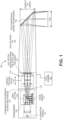
- FIG. 1 schematically illustrates one example of a compact apparatus 100 for confocal scanning of an object.
- the apparatus can comprise a confocal illuminator 101 (light source and/or illumination optics) configured to generate confocal illumination that may be projected onto an object.
- the apparatus may include a spatial pattern disposed on a transparent base, for example, a transparency 105 or a transparent glass plate.
- the light source and any illumination optics may be configured to provide illumination through the spatial pattern and may include a light collector/reflector.
- the light source can be an LED light source (with, e.g., a reflector behind it to direct light through the pattern).
- a conventional confocal spot array light source such as laser diode can be replaced by the LED light source.
- the apparatus can comprise an LED based emitter, which can reduce speckle noise.
- the spatial pattern can comprise an array of segments to achieve spot illumination.
- the apparatus can further comprise a light collector or a light uniformizer to create uniform illumination over the pattern.
- the apparatus can further comprise a condensing lens to condense light beams of the light source.
- the apparatus can comprise a white LED light source readily available for color model capture and rendering, which can enable straightforward color implementation.
- the apparatus can comprise a beam splitter 109 and an image sensor 111.
- the beam splitter may be configured to transmit light beams of the confocal illuminator to the object and reflect light beams returned from the object to the image sensor.
- the image sensor 111 may be configured to receive light beams returned from the object.
- the beam splitter can be a polarization beam splitter (PBS).
- the apparatus can comprise an optical system (including or consisting of projection/imaging optical system/subsystem 115) comprising one or more lenses (e.g., focusing optics 119), and an exit pupil 121.
- the optical system can be configured to project light that passed through the transparency 105 onto the object and to image the object to the image sensor.
- the LED light source can be configured to illuminates the transparency in Köhler illumination mode such that the image of the LED falls on the entrance pupil of the optical system, as shown in FIG. 2 .
- Light leaving the imaging optical system 115 may pass through a hollow front tip 123 until reaching a fold mirror 125 near the distal end of the front tip 123, and be directed out of the tip to the object (e.g., teeth); light returning from the object travels the same path.
- the front tip is hollow, and the entire imaging optical system moves relative to the front tip (e.g., there are no additional optical surfaces between the axially movable imaging optical system and the fold mirror in the front tip).
- FIG. 2 which, like FIG. 1 , shows an optical system including a light source 201 (and may also include imaging optics, such as a condenser lens 203 in this example) and an optical system 207 (e.g., which may include a projection/imaging system).
- the illumination subsystem can be configured to illuminate the pattern (e.g., the transparency 209) and this spatial pattern 209 may be projected onto the object.
- the illuminated object can be imaged back through the imaging subsystem 207.
- the imaging subsystem can be the same as the projection/imaging subsystem between the beam splitter and the fold mirror.
- the imaging path and the projection path may share the same optical path and same optical elements such as the one or more lenses, as shown in FIG. 1 .
- the object can be imaged back through the same optical system and light reflected from the object can be directed onto the image sensor through the beam splitter.
- the apparatus for confocal scanning disclosed herein can be smaller, lighter and lower cost than the conventional confocal optical system.
- the imaging optical system can be mounted on a depth scanning module (axial scanner 135), as shown in FIG. 1 .
- the optical system between the beam splitter and the front tip can be entirely integrated and coupled to the depth scanning module for axial movement relative to the front tip.
- the optical system (and in some variations the depth scanning module) can be integrated into a single optomechanical module as shown in FIG. 1 , which can lead to relaxed production and assembly tolerance.
- the axial scanner can include a linear axial actuator which can translate the optical system axially in a controlled manner, e.g., over 0.5 to 3 mm, to facilitate depth scanning.
- the apparatus can be configured to have high axial magnification to enable simple depth scanning linear actuator.
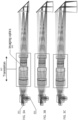
- FIGS. 3A-3C schematically illustrate axially scanning of the apparatus for confocal scanning in a near-focus position ( FIG. 3A ), a mid-focus position ( FIG. 3B ) and a far-focus potion (FIT> 3C) respectively, showing the translation of the entire imaging optical system 307, including projection/imaging optics 305.
- the projected spatial pattern 301 is transmitted onto/in the object and reflected light is received by the sensor 303 for analysis to determine the 3D surface of the object.
- the optical system including the combined projection/imaging subsystem can result in simple projection optics (focus optics) and projection/imaging optics design and reduced the number of optical elements, such as optical lenses.
- the projection optics may refer to the same optics as the imaging optics but in the projection direction (e.g., from the light source onto the object).
- the optical system can comprise less than 10, 9, 5, or 3 optical elements.
- the optical lenses in the optical system can have a diameter of about 5 mm, 8 mm, 10 mm, 14 mm, 15 mm or any values therebetween, while the optical lenses in the conventional confocal optical system may have a diameter of about 25 mm.
- the optical system disclosed herein further eliminated the following elements in a typical conventional confocal scanning apparatus such as dichroic filter, micro-lens, etc.
- the apparatus for confocal scanning disclosed herein is more compact, lighter weight and lower cost than a conventional confocal scanning apparatus.
- the apparatus can have a weight of about 100, 200 or 300 grams in some embodiments.
- the apparatus can have a size less than 150 mm x 25 mm x 25 mm, 140 mm x 20 mm x 20 mm, or 130 mm x 14 mm x 14 mm in some embodiments.
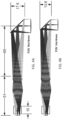
- FIG. 4A schematically illustrates an apparatus for compact confocal scanning comprising a hollow front tip with a field of view (FOV) 18 x 14 mm.
- FIG. 4B illustrate an apparatus for compact confocal scanning comprising a hollow front tip with a field of view (FOV) 14 x 14 mm.
- the apparatus for compact confocal scanning can have a smaller front tip size than conventional confocal scanning apparatus.
- the apparatus can have a front tip height of about 14mm with a FOV of 14x14mm.
- the hollow front tip can comprise a back heated defogging fold mirror.
- the hollow tip can have a dimension of about 90mm x 20mm x 20 mm, 80mm x16mm x16 mm, or 60mm x 14mm x14mm in some embodiments. These dimensions are for illustration only; other dimensions may be used.
- any of the apparatuses described herein may be non-telecentric.
- the projection/imaging optics system may be configured to provide a deviation from telecentricity of a chief ray between the projection/imaging optics system and the fold mirror relative to a scan field size of between 3 and 10 degrees.
- FIG. 5 schematically illustrates an example of a non-telecentric optical system of an apparatus for confocal scanning in one embodiment of the disclosure.
- the optical system can be configured with the light source space non-telecentric aperture imaging such that the optical system is sufficiently compact and lightweight to be translated axially, for example, by a linear actuator such as a voice coil motor (VCM), to facilitate the depth scan.
- VCM voice coil motor
- the exit pupil of the optical system can be located for maximum deviation from telecentricity towards divergent chief rays, which can enable minimal size of a front tip of the apparatus.
- the scanned field size can be the same for all design options, for a specific distance from the tip, for example, a mid-range of a scan depth.
- the deviation angle from telecentricity can be determined by the exit pupil distance from the object focus and the field size.
- the tip height can be derived by the footprint of the beams of the light source on the folding mirror. This height can be smaller as the exit pupil gets closer to the object focus (forward exit pupil).
- Possible range of deviation angle from telecentricity can be from about 3 degrees to about 10 degrees.
- the deviation angle from telecentricity can be about 8.5 degrees in some embodiments.
- the deviation angle from telecentricity is for the field extent in the mirror folding plane, which has effect on the tip height.
- FIG. 6 schematically illustrates an example of a confocal illuminator of an apparatus for confocal scanning where a transparency (including a spatial pattern) is bonded directly to a beam splitter or mounted on a fixture relative to the beam splitter in one embodiment.
- the transparency can be bonded directly onto one facet the beam splitter, for example, onto a first surface of a beam splitter (e.g., Polarizing Beam Splitter, PBS) while the image sensor can be bonded onto another facet (e.g., a second surface) of the beam splitter perpendicular to the transparency, thus maintaining stable relative position ("confocal condition") between the image sensor and the transparency as shown in FIG. 6 .
- the apparatus can be configured for drift invariant confocal conjugation.
- the transparency and the image sensor can be disposed on conjugate planes of the object.
- the apparatus can further support monolithic confocal conjugate assembly. Pattern based illumination enables conjugate imaging onto the image sensor, which is invariant to relative lateral shift.
- the apparatus for confocal scanning can be configured to have position invariant correlation, which may be less sensitive to assembly drift.
- FIGS. 7A and 7B illustrates examples of spatial patterns that may be used as part of any of the compact apparatuses for 3D confocal scanning described herein.
- FIG. 7A illustrates an example of a disordered pattern of an apparatus for confocal scanning.
- FIG. 7B illustrates an example of an ordered pattern of an apparatus for confocal scanning.
- the apparatus for confocal scanning can comprise an illuminated pattern to replace an array of light beams in a conventional confocal scanning apparatus.
- a white LED back illuminated pattern can be used to achieve confocal imaging.
- a variety of patterns can be used in the confocal illuminator, which enables design flexibility and lower signal requirement.
- the pattern can comprise an array of segments to achieve spot-illumination equivalent.
- the illumination spots through the pattern can be nearly diffraction limited.
- the pattern can comprise an array of segments that have a size similar to pinholes in a conventional confocal microscope.
- the pattern can comprise an array of segments that have a diameter of about 1 ⁇ m, 10 ⁇ m, 25 ⁇ m, 50 ⁇ m, 1 mm or 2 mm or any values therebetween.
- the apparatus for confocal scanning can further comprise an array of detection pinholes.
- the detection pinholes can be disposed in a fixture between the beam splitter and the image sensor.
- the detection pinholes can be bonded or integrated in the image sensor.
- the size of the pinholes can be configured adapted to the numerical aperture (NA) of the optical system and the wavelength of the light source.
- the size of the detection pinholes can be further adapted to a magnification of the optical system.
- the confocal position can be determination by maximum correlation.
- a reference pattern position can be invariant.
- a depth position per pixel or a group of pixels of the image sensor can be assigned corresponding to the maximum signal obtained on the pixel or the group of pixels following a depth scan.
- Lateral resolution need not be compromised because all pixels within region of interest (ROI) can be used.
- ROI region of interest
- resolution can be improved by sub-pixel processing
- the method can comprise activating a confocal illuminator configured to generate confocal illumination to an object.
- the method can comprise using the confocal illuminator comprising a spatial pattern disposed on a transparent base and a light source configured to provide illumination to the spatial pattern, and/or any additional illumination optics (e.g., lenses).
- the method can comprise illuminating a pattern, projecting the pattern onto an object, and imaging the object by an optical system comprising projecting/imaging optics including one or more lenses and having an optical axis.
- the method can comprise scanning the object by a depth scanning module configured to be movable along the optical axis.
- the method can comprise projecting beams of light from the confocal illuminator through a beam splitter, onto the object, and directing light returning from the object onto an imaging sensor using the beam splitter.
- the method can comprise using a spatial pattern on the transparent base that is not time varying.
- the method can comprise using the spatial pattern and the transparent base, wherein the pattern (e.g., a transparency) is bonded onto a first side of the beam splitter, further wherein the image sensor is bonded to a second side of the beam splitter perpendicular to the first side to maintain stable relative position between the image sensor and the spatial pattern.
- the pattern e.g., a transparency
- a method can comprise disposing an image of the light source at an entrance pupil of the optical system.
- the method can comprise disposing the spatial pattern at a conjugate plane of the image sensor such that a position of an image of the object is invariant to relative lateral shift of the spatial pattern to the image sensor.
- the method can comprise disposing an exit pupil of the optical system for maximum deviation from telecentricity towards divergent chief rays.
- a method can comprise disposing scanning the object comprises moving the depth scanning as a unit along the optical axis for a range between 0.1 mm to 5 mm to have a depth scanning range between 5 mm to 40 mm.
- the method can comprise determining a confocal position by maximum correlation.
- the apparatuses and methods described herein may also be configured as structured light scanning systems and/or light-field 3D reconstruction systems.
- light field data may be captured, for example, by including configuring the imaging system as a plenotoptic apparatus, for example, by including a plurality of micro-lenses before or after the focal plane of the main lensing sub-system (e.g., the compact focusing optics).
- the light may pass through an optical surface (the micro-lenses) between the exit pupil and the fold mirror in the optical axis alternatively, the micro-lenses may from part of the compact focusing optics.
- a depth map may be created from the light field data, and this depth map may8 be used to create surfaces.
- Traditional stereo imaging methods may be used for depth map extraction, or depth data may be extracted from light field cameras by combining two or more methods of depth estimation.
- FIG. 8 illustrates another example of a method as described herein.
- the method for confocal three-dimensional scanning includes first illuminating a spatial pattern on a first side of a beam splitter and projecting the spatial pattern down an optical axis, through the beam splitter, through an integrated projection/imaging optics system comprising an optical gain and focusing lens and an exit pupil, out of the exit pupil and though a hollow tip front extending from the projection/imaging optics system to a fold mirror at a distal end of the hollow tip front, without passing through an optical surface between the exit pupil and the fold mirror in the optical axis 801.
- the method then includes projecting the spatial pattern on a target 803 and transmitting reflected light from the target back through the hollow tip, into the projection/imaging optics system, through the beam splitter and into an image sensor on a second side of the beam splitter 805.
- the method may also include scanning the target by axially moving the entire projection/imaging optics system in the optical axis relative to the fold mirror 807, wherein the projection/imaging optics system is configured to provide a deviation from telecentricity of a chief ray between the projection/imaging optics system and the fold mirror relative to a scan field size of between 3 and 10 degrees.
- the systems, devices, and methods of the preferred embodiments and variations thereof can be embodied and/or implemented at least in part as a machine configured to receive a computer-readable medium storing computer-readable instructions.
- the instructions are preferably executed by computer-executable components preferably integrated with the system including the computing device configured with software.
- the computer-readable medium can be stored on any suitable computer-readable media such as RAMs, ROMs, flash memory, EEPROMs, optical devices (e.g., CD or DVD), hard drives, floppy drives, or any suitable device.
- the computer-executable component is preferably a general or application-specific processor, but any suitable dedicated hardware or hardware/firmware combination can alternatively or additionally execute the instructions.
- references to a structure or feature that is disposed "adjacent" another feature may have portions that overlap or underlie the adjacent feature.
- the device may be otherwise oriented (rotated 90 degrees or at other orientations) and the spatially relative descriptors used herein interpreted accordingly.
- the terms “upwardly”, “downwardly”, “vertical”, “horizontal” and the like are used herein for the purpose of explanation only unless specifically indicated otherwise.
- first and second may be used herein to describe various features/elements (including steps), these features/elements should not be limited by these terms, unless the context indicates otherwise. These terms may be used to distinguish one feature/element from another feature/element. Thus, a first feature/element discussed below could be termed a second feature/element, and similarly, a second feature/element discussed below could be termed a first feature/element without departing from the scope of the present invention as defined by the claims.
- any of the apparatuses and methods described herein should be understood to be inclusive, but all or a sub-set of the components and/or steps may alternatively be exclusive, and may be expressed as “consisting of” or alternatively “consisting essentially of” the various components, steps, sub-components or sub-steps.
- a numeric value may have a value that is +/- 0.1% of the stated value (or range of values), +/- 1% of the stated value (or range of values), +/- 2% of the stated value (or range of values), +/- 5% of the stated value (or range of values), +/- 10% of the stated value (or range of values), etc.
- Any numerical values given herein should also be understood to include about or approximately that value, unless the context indicates otherwise. For example, if the value "10" is disclosed, then “about 10" is also disclosed. Any numerical range recited herein is intended to include all sub-ranges subsumed therein.
Landscapes
- Health & Medical Sciences (AREA)
- Physics & Mathematics (AREA)
- Life Sciences & Earth Sciences (AREA)
- General Health & Medical Sciences (AREA)
- Public Health (AREA)
- Veterinary Medicine (AREA)
- Animal Behavior & Ethology (AREA)
- Engineering & Computer Science (AREA)
- Optics & Photonics (AREA)
- Surgery (AREA)
- Dentistry (AREA)
- Oral & Maxillofacial Surgery (AREA)
- General Physics & Mathematics (AREA)
- Heart & Thoracic Surgery (AREA)
- Biophysics (AREA)
- Biomedical Technology (AREA)
- Pathology (AREA)
- Medical Informatics (AREA)
- Molecular Biology (AREA)
- Radiology & Medical Imaging (AREA)
- Chemical & Material Sciences (AREA)
- Analytical Chemistry (AREA)
- Epidemiology (AREA)
- Nuclear Medicine, Radiotherapy & Molecular Imaging (AREA)
- Multimedia (AREA)
- Audiology, Speech & Language Pathology (AREA)
- Computer Vision & Pattern Recognition (AREA)
- Ophthalmology & Optometry (AREA)
- General Engineering & Computer Science (AREA)
- Microscoopes, Condenser (AREA)
- Lenses (AREA)
- Endoscopes (AREA)
- Dental Tools And Instruments Or Auxiliary Dental Instruments (AREA)
Claims (15)
- Tragbare Vorrichtung (100) zur konfokalen dreidimensionalen Abtastung, wobei die Vorrichtung Folgendes umfasst:eine Lichtquelle (101);eine Transparenz (105), auf der ein räumliches Muster angeordnet ist und die konfiguriert ist, um durch die Lichtquelle beleuchtet zu werden;einen Strahlteiler (109) mit einer ersten Oberfläche, einer zweiten Oberfläche und einem Bildsensor (111) auf der zweiten Oberfläche;eine vordere Spitze (123), die sich von einem Projektions-/Bildgebungsoptiksystem (115) in einer optischen Achse erstreckt und einen Faltspiegel (125) an einem distalen Ende der vorderen Spitze umfasst;ein einzelnes bewegbares optomechanisches Modul, welches das Projektions-/Bildgebungsoptiksystem (115) umfasst, das nicht telezentrisch ist, eine oder mehrere Linsen (119) und eine angeordnete Austrittspupille (121) umfasst, wobei das Projektions-/Bildgebungsoptiksystem die optische Achse aufweist, wobei das Projektions-/Bildgebungsoptiksystem (115) zwischen dem Strahlteiler (109) und der vorderen Spitze (123) vollständig in das einzelne bewegbare optomechanische Modul integriert ist, und wobei das Projektions-/Bildgebungsoptiksystem eine Abweichung von Telezentrizität eines Hauptstrahls zwischen dem Projektions-/Bildgebungsoptiksystem und dem Faltspiegel relativ zu einer Abtastfeldgröße von 3 Grad oder mehr bereitstellt,
undeinen axialen Aktor, der an das Projektions-/Bildgebungsoptiksystem (115) gekoppelt und konfiguriert ist, um das einzelne bewegbare optomechanische Modul zu bewegen, das eine Gesamtheit des Projektions-/Bildgebungsoptiksystems umfasst, beinhaltend die eine oder mehreren Linsen (119) und die Austrittspupille (121) in der optischen Achse relativ zu dem Faltspiegel (125). - Vorrichtung nach Anspruch 1, wobei das Projektions-/Bildgebungsoptiksystem (115) konfiguriert ist, um eine Abweichung von Telezentrizität eines Hauptstrahls zwischen dem Projektions-/Bildgebungsoptiksystem und dem Faltspiegel relativ zu einer Abtastfeldgröße von zwischen 3 und 10 Grad bereitzustellen.
- Vorrichtung nach Anspruch 1, wobei die Transparenz (105) an der ersten Oberfläche des Strahlteilers (109) angebracht ist.
- Vorrichtung nach Anspruch 1, wobei das räumliche Muster auf der Transparenz (105) nicht zeitlich variiert.
- Vorrichtung nach Anspruch 1, wobei der Strahlteiler (109) einen polarisationsempfindlichen Strahlteiler umfasst, und wobei die Transparenz (105) auf die erste Oberfläche des Strahlteilers geklebt ist und der Bildsensor (111) an die zweite Oberfläche des Strahlteilers (109) senkrecht zu der ersten Oberfläche geklebt ist, um stabile relative Position zwischen dem Bildsensor und dem räumlichen Muster aufrechtzuerhalten.
- Vorrichtung nach Anspruch 1, wobei die Vorrichtung konfiguriert ist, sodass ein Bild der Lichtquelle (101) an einer Eintrittspupille des Projektions-/Bildgebungssoptiksystems positioniert ist.
- Vorrichtung nach Anspruch 1, wobei die vordere Spitze (123) konfiguriert ist, um entfernbar und autoklavierbar zu sein.
- Vorrichtung nach Anspruch 1, wobei zumindest eines von Folgendem gilt: a) die vordere Spitze (123) weist eine Größe von weniger als 140 mm x 20 mm x 20 mm auf, b) die vordere Spitze (123) weist eine Höhe von 20 mm oder weniger auf, c) der Faltspiegel (125) ist 45 Grad zu der optischen Achse an dem distalen Ende der vorderen Spitze angeordnet, d) die Vorrichtung weist ein Gewicht von 300 Gramm oder weniger auf, oder e) ein Durchmesser des Projektions-/Bildgebungsoptiksystems (115) in der optischen Achse ist 15 mm oder weniger.
- Vorrichtung nach Anspruch 1, wobei das Projektions-/Bildgebungsoptiksystem (115) konfiguriert ist, um als Einheit entlang der optischen Achse für einen Bereich zwischen 0,1 mm bis 5 mm bewegbar zu sein und einen Tiefenabtastbereich zwischen 5 mm bis 40 mm aufzuweisen.
- Vorrichtung nach Anspruch 1, wobei eine letzte optische Oberfläche von der Fokussieroptik eine Viertelwellenplatte, QWP, ist.
- Verfahren zur konfokalen dreidimensionalen Abtastung unter Verwendung einer tragbaren Vorrichtung (100), wobei das Verfahren Folgendes umfasst:Beleuchten eines räumlichen Musters, das auf einer Transparenz (105) angeordnet ist, die an einer ersten Seite eines Strahlteilers (109) angebracht ist, und Projizieren des räumlichen Musters eine optische Achse hinab, durch den Strahlteiler, durch ein integriertes Projektions-/Bildgebungsoptiksystem (115), das nicht telezentrisch ist und eine oder mehrere Linsen (119) und eine angeordnete Austrittspupille (121) umfasst, aus der Austrittspupille und durch eine vordere Spitze (123), die sich von dem Projektions-/Bildgebungsoptiksystem (115) zu einem Faltspiegel (125) an einem distalen Ende der vorderen Spitze erstreckt, wobei das integrierte Projektions-/Bildgebungsoptiksystem (115) zwischen dem Strahlteiler (109) und der vorderen Spitze (123) eine Abweichung von Telezentrizität eines Hauptstrahls zwischen dem Projektions-/Bildgebungsoptiksystem und dem Faltspiegel relativ zu einer Abtastfeldgröße von 3 Grad oder mehr bereitstellt, und wobei das integrierte Projektions-/Bildgebungsoptiksystem vollständig in ein einzelnes bewegbares optomechanisches Modul integriert ist;Projizieren des räumlichen Musters auf ein Ziel;Übertragen von reflektiertem Licht von dem Ziel zurück durch die vordere Spitze (123), in das Projektions-/Bildgebungsoptiksystem (115), durch den Strahlteiler (109) und in einen Bildsensor (111) auf einer zweiten Seite des Strahlteilers; undAbtasten des Ziels durch axiales Bewegen des einzelnen bewegbaren optomechanischen Moduls, das eine Gesamtheit des Projektions-/Bildgebungsoptiksystem (115) beinhaltend die eine oder mehreren Linsen (119) und die Austrittspupille (121) in der optischen Achse relativ zu dem Faltspiegel (125) umfasst.
- Verfahren nach Anspruch 11, wobei das Abtasten Abtasten mit 10 Hz oder größer umfasst.
- Verfahren nach Anspruch 11, wobei das Beleuchten des räumlichen Musters Beleuchten eines räumlichen Musters umfasst, das nicht zeitlich variiert.
- Verfahren nach Anspruch 11, wobei das Beleuchten des räumlichen Musters Beleuchten von zumindest einem Teil einer Transparenz (105) umfasst, die auf eine erste Seite des Strahlteilers (109) geklebt ist, wobei ferner der Bildsensor (111) an eine zweite Seite des Strahlteilers senkrecht zu der ersten Seite geklebt ist, um stabile relative Position zwischen dem Bildsensor und dem räumlichen Muster aufrechtzuerhalten.
- Verfahren nach Anspruch 11, wobei das Abtasten des Ziels Bewegen des einzelnen bewegbaren optomechanischen Moduls entlang der optischen Achse für einen Bereich zwischen 0,1 mm bis 5 mm umfasst, um einen Tiefenabtastbereich zwischen 5 mm bis 40 mm aufzuweisen.
Applications Claiming Priority (3)
| Application Number | Priority Date | Filing Date | Title |
|---|---|---|---|
| US201762445663P | 2017-01-12 | 2017-01-12 | |
| US15/859,010 US10456043B2 (en) | 2017-01-12 | 2017-12-29 | Compact confocal dental scanning apparatus |
| PCT/US2018/013321 WO2018132569A1 (en) | 2017-01-12 | 2018-01-11 | Compact confocal dental scanning apparatus |
Publications (3)
| Publication Number | Publication Date |
|---|---|
| EP3568064A1 EP3568064A1 (de) | 2019-11-20 |
| EP3568064C0 EP3568064C0 (de) | 2025-01-22 |
| EP3568064B1 true EP3568064B1 (de) | 2025-01-22 |
Family
ID=62782485
Family Applications (1)
| Application Number | Title | Priority Date | Filing Date |
|---|---|---|---|
| EP18702020.1A Active EP3568064B1 (de) | 2017-01-12 | 2018-01-11 | Kompakte vorrichtung zur konfokalen dentalen abtastung |
Country Status (4)
| Country | Link |
|---|---|
| US (6) | US10456043B2 (de) |
| EP (1) | EP3568064B1 (de) |
| CN (2) | CN116172501A (de) |
| WO (1) | WO2018132569A1 (de) |
Families Citing this family (130)
| Publication number | Priority date | Publication date | Assignee | Title |
|---|---|---|---|---|
| US11026768B2 (en) | 1998-10-08 | 2021-06-08 | Align Technology, Inc. | Dental appliance reinforcement |
| US9492245B2 (en) | 2004-02-27 | 2016-11-15 | Align Technology, Inc. | Method and system for providing dynamic orthodontic assessment and treatment profiles |
| EP1607041B1 (de) | 2004-06-17 | 2008-01-16 | Cadent Ltd. | Verfahren zum Bereitstellen von Daten im Zusammenhang mit der Mundhöhle |
| US7916911B2 (en) | 2007-02-26 | 2011-03-29 | Align Technology, Inc. | System and method for digital tooth imaging |
| US7878805B2 (en) | 2007-05-25 | 2011-02-01 | Align Technology, Inc. | Tabbed dental appliance |
| US8738394B2 (en) | 2007-11-08 | 2014-05-27 | Eric E. Kuo | Clinical data file |
| US8108189B2 (en) | 2008-03-25 | 2012-01-31 | Align Technologies, Inc. | Reconstruction of non-visible part of tooth |
| US9492243B2 (en) | 2008-05-23 | 2016-11-15 | Align Technology, Inc. | Dental implant positioning |
| US8092215B2 (en) | 2008-05-23 | 2012-01-10 | Align Technology, Inc. | Smile designer |
| US8172569B2 (en) | 2008-06-12 | 2012-05-08 | Align Technology, Inc. | Dental appliance |
| US8152518B2 (en) | 2008-10-08 | 2012-04-10 | Align Technology, Inc. | Dental positioning appliance having metallic portion |
| US8292617B2 (en) | 2009-03-19 | 2012-10-23 | Align Technology, Inc. | Dental wire attachment |
| US8765031B2 (en) | 2009-08-13 | 2014-07-01 | Align Technology, Inc. | Method of forming a dental appliance |
| US9848958B2 (en) | 2009-11-02 | 2017-12-26 | Align Technology, Inc. | Generating a dynamic three-dimensional occlusogram |
| US9241774B2 (en) | 2010-04-30 | 2016-01-26 | Align Technology, Inc. | Patterned dental positioning appliance |
| US9211166B2 (en) | 2010-04-30 | 2015-12-15 | Align Technology, Inc. | Individualized orthodontic treatment index |
| ES2848157T3 (es) | 2010-07-19 | 2021-08-05 | Align Technology Inc | Procedimientos y sistemas para crear e interactuar con modelos virtuales tridimensionales |
| US9403238B2 (en) | 2011-09-21 | 2016-08-02 | Align Technology, Inc. | Laser cutting |
| US9375300B2 (en) | 2012-02-02 | 2016-06-28 | Align Technology, Inc. | Identifying forces on a tooth |
| US9220580B2 (en) | 2012-03-01 | 2015-12-29 | Align Technology, Inc. | Determining a dental treatment difficulty |
| US9414897B2 (en) | 2012-05-22 | 2016-08-16 | Align Technology, Inc. | Adjustment of tooth position in a virtual dental model |
| US9192305B2 (en) | 2012-09-28 | 2015-11-24 | Align Technology, Inc. | Estimating a surface texture of a tooth |
| US8948482B2 (en) | 2012-11-01 | 2015-02-03 | Align Technology, Inc. | Motion compensation in a three dimensional scan |
| US10098714B2 (en) | 2012-12-19 | 2018-10-16 | Align Technology, Inc. | Apparatus and method for optically scanning an object in registration with a reference pattern |
| US9668829B2 (en) | 2012-12-19 | 2017-06-06 | Align Technology, Inc. | Methods and systems for dental procedures |
| US9393087B2 (en) | 2013-08-01 | 2016-07-19 | Align Technology, Inc. | Methods and systems for generating color images |
| US10111714B2 (en) | 2014-01-27 | 2018-10-30 | Align Technology, Inc. | Adhesive objects for improving image registration of intraoral images |
| US10111581B2 (en) * | 2014-02-27 | 2018-10-30 | Align Technology, Inc. | Thermal defogging system and method |
| US9510757B2 (en) | 2014-05-07 | 2016-12-06 | Align Technology, Inc. | Identification of areas of interest during intraoral scans |
| US9431887B2 (en) | 2014-06-06 | 2016-08-30 | Align Technology, Inc. | Lens positioning system |
| US9491863B2 (en) | 2014-06-26 | 2016-11-08 | Align Technology, Inc. | Mounting system that maintains stability of optics as temperature changes |
| US9439568B2 (en) | 2014-07-03 | 2016-09-13 | Align Technology, Inc. | Apparatus and method for measuring surface topography optically |
| US10772506B2 (en) | 2014-07-07 | 2020-09-15 | Align Technology, Inc. | Apparatus for dental confocal imaging |
| US9675430B2 (en) | 2014-08-15 | 2017-06-13 | Align Technology, Inc. | Confocal imaging apparatus with curved focal surface |
| US9724177B2 (en) | 2014-08-19 | 2017-08-08 | Align Technology, Inc. | Viewfinder with real-time tracking for intraoral scanning |
| US9660418B2 (en) | 2014-08-27 | 2017-05-23 | Align Technology, Inc. | VCSEL based low coherence emitter for confocal 3D scanner |
| US10449016B2 (en) | 2014-09-19 | 2019-10-22 | Align Technology, Inc. | Arch adjustment appliance |
| US9744001B2 (en) | 2014-11-13 | 2017-08-29 | Align Technology, Inc. | Dental appliance with cavity for an unerupted or erupting tooth |
| US10453269B2 (en) | 2014-12-08 | 2019-10-22 | Align Technology, Inc. | Intraoral scanning using ultrasound and optical scan data |
| US10504386B2 (en) | 2015-01-27 | 2019-12-10 | Align Technology, Inc. | Training method and system for oral-cavity-imaging-and-modeling equipment |
| US10076389B2 (en) | 2015-02-13 | 2018-09-18 | Align Technology, Inc. | Three-dimensional tooth modeling using a two-dimensional x-ray image |
| US9451873B1 (en) | 2015-03-06 | 2016-09-27 | Align Technology, Inc. | Automatic selection and locking of intraoral images |
| US10108269B2 (en) | 2015-03-06 | 2018-10-23 | Align Technology, Inc. | Intraoral scanner with touch sensitive input |
| US9844426B2 (en) | 2015-03-12 | 2017-12-19 | Align Technology, Inc. | Digital dental tray |
| US10248883B2 (en) | 2015-08-20 | 2019-04-02 | Align Technology, Inc. | Photograph-based assessment of dental treatments and procedures |
| US11554000B2 (en) | 2015-11-12 | 2023-01-17 | Align Technology, Inc. | Dental attachment formation structure |
| US11931222B2 (en) | 2015-11-12 | 2024-03-19 | Align Technology, Inc. | Dental attachment formation structures |
| US11596502B2 (en) | 2015-12-09 | 2023-03-07 | Align Technology, Inc. | Dental attachment placement structure |
| US11103330B2 (en) | 2015-12-09 | 2021-08-31 | Align Technology, Inc. | Dental attachment placement structure |
| US10470847B2 (en) | 2016-06-17 | 2019-11-12 | Align Technology, Inc. | Intraoral appliances with sensing |
| US10383705B2 (en) | 2016-06-17 | 2019-08-20 | Align Technology, Inc. | Orthodontic appliance performance monitor |
| US10136972B2 (en) | 2016-06-30 | 2018-11-27 | Align Technology, Inc. | Historical scan reference for intraoral scans |
| US10507087B2 (en) | 2016-07-27 | 2019-12-17 | Align Technology, Inc. | Methods and apparatuses for forming a three-dimensional volumetric model of a subject's teeth |
| AU2017302364B2 (en) | 2016-07-27 | 2022-09-22 | Align Technology, Inc. | Intraoral scanner with dental diagnostics capabilities |
| CN117257492A (zh) | 2016-11-04 | 2023-12-22 | 阿莱恩技术有限公司 | 用于牙齿图像的方法和装置 |
| WO2018102770A1 (en) | 2016-12-02 | 2018-06-07 | Align Technology, Inc. | Force control, stop mechanism, regulating structure of removable arch adjustment appliance |
| US10695150B2 (en) | 2016-12-16 | 2020-06-30 | Align Technology, Inc. | Augmented reality enhancements for intraoral scanning |
| US10548700B2 (en) | 2016-12-16 | 2020-02-04 | Align Technology, Inc. | Dental appliance etch template |
| US10456043B2 (en) | 2017-01-12 | 2019-10-29 | Align Technology, Inc. | Compact confocal dental scanning apparatus |
| US10779718B2 (en) | 2017-02-13 | 2020-09-22 | Align Technology, Inc. | Cheek retractor and mobile device holder |
| US10499793B2 (en) | 2017-02-17 | 2019-12-10 | Align Technology, Inc. | Longitudinal analysis and visualization under limited accuracy system |
| WO2018183358A1 (en) | 2017-03-27 | 2018-10-04 | Align Technology, Inc. | Apparatuses and methods assisting in dental therapies |
| US10613515B2 (en) | 2017-03-31 | 2020-04-07 | Align Technology, Inc. | Orthodontic appliances including at least partially un-erupted teeth and method of forming them |
| US11045283B2 (en) | 2017-06-09 | 2021-06-29 | Align Technology, Inc. | Palatal expander with skeletal anchorage devices |
| US10708574B2 (en) | 2017-06-15 | 2020-07-07 | Align Technology, Inc. | Three dimensional imaging apparatus with color sensor |
| CN110769777B (zh) | 2017-06-16 | 2023-08-11 | 阿莱恩技术有限公司 | 牙齿类型和萌出状态的自动检测 |
| US10639134B2 (en) | 2017-06-26 | 2020-05-05 | Align Technology, Inc. | Biosensor performance indicator for intraoral appliances |
| US10885521B2 (en) | 2017-07-17 | 2021-01-05 | Align Technology, Inc. | Method and apparatuses for interactive ordering of dental aligners |
| WO2019018784A1 (en) | 2017-07-21 | 2019-01-24 | Align Technology, Inc. | ANCHOR OF CONTOUR PALATIN |
| CN115462921B (zh) | 2017-07-27 | 2025-05-06 | 阿莱恩技术有限公司 | 牙齿着色、透明度和上釉 |
| CN116327391A (zh) | 2017-07-27 | 2023-06-27 | 阿莱恩技术有限公司 | 用于通过光学相干断层扫描术来处理正畸矫正器的系统和方法 |
| US12274597B2 (en) | 2017-08-11 | 2025-04-15 | Align Technology, Inc. | Dental attachment template tray systems |
| US11116605B2 (en) | 2017-08-15 | 2021-09-14 | Align Technology, Inc. | Buccal corridor assessment and computation |
| US20200197136A1 (en) * | 2017-08-17 | 2020-06-25 | Trophy | Stencil for intraoral surface scanning |
| WO2019036677A1 (en) | 2017-08-17 | 2019-02-21 | Align Technology, Inc. | SURVEILLANCE OF CONFORMITY OF DENTAL DEVICE |
| US12171575B2 (en) | 2017-10-04 | 2024-12-24 | Align Technology, Inc. | Intraoral systems and methods for sampling soft-tissue |
| CN111565668B (zh) | 2017-10-27 | 2022-06-07 | 阿莱恩技术有限公司 | 替代咬合调整结构 |
| CN116602778A (zh) | 2017-10-31 | 2023-08-18 | 阿莱恩技术有限公司 | 具有选择性牙合负荷和受控牙尖交错的牙科器具 |
| WO2019089989A2 (en) | 2017-11-01 | 2019-05-09 | Align Technology, Inc. | Automatic treatment planning |
| WO2019100022A1 (en) | 2017-11-17 | 2019-05-23 | Align Technology, Inc. | Orthodontic retainers |
| EP3716885B1 (de) | 2017-11-30 | 2023-08-30 | Align Technology, Inc. | Sensoren umfassende orthodontische intraorale geräte |
| US11432908B2 (en) | 2017-12-15 | 2022-09-06 | Align Technology, Inc. | Closed loop adaptive orthodontic treatment methods and apparatuses |
| US10980613B2 (en) | 2017-12-29 | 2021-04-20 | Align Technology, Inc. | Augmented reality enhancements for dental practitioners |
| WO2019147868A1 (en) | 2018-01-26 | 2019-08-01 | Align Technology, Inc. | Visual prosthetic and orthodontic treatment planning |
| CN111655191B (zh) | 2018-01-26 | 2022-04-08 | 阿莱恩技术有限公司 | 诊断性口内扫描和追踪 |
| US11937991B2 (en) | 2018-03-27 | 2024-03-26 | Align Technology, Inc. | Dental attachment placement structure |
| DE102018107710B4 (de) * | 2018-03-29 | 2021-01-14 | Dürr Dental SE | Intraoraler parallelkonfokaler Oberflächenscanner mit Störlichtsubtraktion |
| JP7374121B2 (ja) | 2018-04-11 | 2023-11-06 | アライン テクノロジー, インコーポレイテッド | 解除可能な口蓋拡張器 |
| US10753734B2 (en) | 2018-06-08 | 2020-08-25 | Dentsply Sirona Inc. | Device, method and system for generating dynamic projection patterns in a confocal camera |
| US11096765B2 (en) * | 2018-06-22 | 2021-08-24 | Align Technology, Inc. | Light field intraoral 3D scanner with structured light illumination |
| DK3628271T3 (da) | 2018-09-27 | 2021-09-06 | Sirona Dental Systems Gmbh | Apparat til ændring af et fokuspunkt for et optisk system i en dental 3d-scanner og dental 3d-scanner |
| US11744681B2 (en) | 2019-03-08 | 2023-09-05 | Align Technology, Inc. | Foreign object identification and image augmentation for intraoral scanning |
| CN113677262B (zh) | 2019-04-05 | 2025-01-03 | 阿莱恩技术有限公司 | 口内扫描仪套的认证和识别 |
| US11238586B2 (en) | 2019-05-02 | 2022-02-01 | Align Technology, Inc. | Excess material removal using machine learning |
| US11455727B2 (en) | 2019-05-02 | 2022-09-27 | Align Technology, Inc. | Method and apparatus for excessive materials removal from intraoral scans |
| US10849723B1 (en) | 2019-05-07 | 2020-12-01 | Sdc U.S. Smilepay Spv | Scanning device |
| US11563929B2 (en) | 2019-06-24 | 2023-01-24 | Align Technology, Inc. | Intraoral 3D scanner employing multiple miniature cameras and multiple miniature pattern projectors |
| EP4537735A3 (de) | 2019-07-29 | 2025-07-02 | Align Technology, Inc. | Vollscannerbarriere für eine intraorale vorrichtung |
| WO2021050774A1 (en) | 2019-09-10 | 2021-03-18 | Align Technology, Inc. | Dental panoramic views |
| US12042124B2 (en) | 2019-10-24 | 2024-07-23 | Align Technology, Inc. | Reflection suppression using fluorescence |
| US11937996B2 (en) | 2019-11-05 | 2024-03-26 | Align Technology, Inc. | Face capture and intraoral scanner and methods of use |
| US12076200B2 (en) | 2019-11-12 | 2024-09-03 | Align Technology, Inc. | Digital 3D models of dental arches with accurate arch width |
| WO2021127100A1 (en) * | 2019-12-17 | 2021-06-24 | Teufel Clayton Adams | Intraoral scanning with raw depth data |
| US12144661B2 (en) | 2019-12-31 | 2024-11-19 | Align Technology, Inc. | Gesture control using an intraoral scanner |
| US12205689B2 (en) * | 2020-01-13 | 2025-01-21 | The Catholic University Of Korea Industry—Academic Cooperation Foundation | Dental medical record device and dental medical record method thereof |
| US12453473B2 (en) | 2020-04-15 | 2025-10-28 | Align Technology, Inc. | Smart scanning for intraoral scanners |
| DE102020208368A1 (de) | 2020-07-03 | 2022-01-05 | Fraunhofer-Gesellschaft zur Förderung der angewandten Forschung eingetragener Verein | Verfahren und Vorrichtung zur Ermittlung einer dreidimensionalen Form |
| US11806210B2 (en) | 2020-10-12 | 2023-11-07 | Align Technology, Inc. | Method for sub-gingival intraoral scanning |
| US12033742B2 (en) | 2020-12-11 | 2024-07-09 | Align Technology, Inc. | Noninvasive multimodal oral assessment and disease diagnoses apparatus and method |
| US12127814B2 (en) | 2020-12-30 | 2024-10-29 | Align Technology, Inc. | Dental diagnostics hub |
| US12303111B2 (en) * | 2021-01-18 | 2025-05-20 | Medit Corp. | Three-dimensional scanner |
| US12426999B2 (en) | 2021-01-26 | 2025-09-30 | Align Technology, Inc. | Distributed intraoral scanning system |
| USD1026227S1 (en) | 2021-01-29 | 2024-05-07 | Align Technology, Inc. | Intraoral scanning system cart |
| USD1061895S1 (en) | 2021-01-29 | 2025-02-11 | Align Technology, Inc. | Portable intraoral scanning device |
| US12329560B2 (en) | 2021-03-22 | 2025-06-17 | Align Technology, Inc. | Systems for guiding dental imaging |
| CA3152850A1 (en) | 2021-03-23 | 2022-09-23 | Tactile Robotics Ltd. | Automated measurement apparatus and method for quantifying dimensions of dental preparation |
| WO2022217269A1 (en) | 2021-04-09 | 2022-10-13 | Align Technology, Inc. | Capturing true bite and occlusion contacts |
| USD1027186S1 (en) | 2022-02-17 | 2024-05-14 | Align Technology, Inc. | Dental imaging attachment for a smartphone |
| JP7632042B2 (ja) * | 2021-05-11 | 2025-02-19 | コニカミノルタ株式会社 | 口腔内測定装置 |
| USD1073069S1 (en) | 2021-05-18 | 2025-04-29 | Align Technology, Inc. | Protective sleeve for an intraoral scanner |
| US12329358B2 (en) | 2021-05-18 | 2025-06-17 | Align Technology, Inc. | Intraoral scanner sleeve |
| US12402988B2 (en) | 2021-07-21 | 2025-09-02 | Align Technology, Inc. | Multimodal intraoral scanning |
| US12310819B2 (en) | 2021-07-23 | 2025-05-27 | Align Technology, Inc. | Intraoral scanner with illumination sequencing and controlled polarization |
| US12370025B2 (en) | 2021-08-06 | 2025-07-29 | Align Technology, Inc. | Intuitive intraoral scanning |
| US20240374357A1 (en) * | 2021-09-10 | 2024-11-14 | 3Shape A/S | Compact intraoral 3d-scanner and a method of optimizing such |
| WO2023075545A1 (ko) * | 2021-10-29 | 2023-05-04 | 아크리얼 주식회사 | 구강 스캐너 |
| USD1042842S1 (en) | 2022-02-18 | 2024-09-17 | Align Technology, Inc. | Intraoral scanner wand |
| US12059316B2 (en) | 2022-09-08 | 2024-08-13 | Enamel Pure | Systems and methods for dental treatment and verification |
| WO2025049808A1 (en) | 2023-08-31 | 2025-03-06 | Align Technology, Inc. | Orthodontic treatment planning based on reinforcement learning |
| US12333722B1 (en) | 2024-03-28 | 2025-06-17 | Enamel Pure, Inc. | Systems and methods for predicting medical conditions usingmachine learning correlating dental images and medical data |
Family Cites Families (618)
| Publication number | Priority date | Publication date | Assignee | Title |
|---|---|---|---|---|
| US2171695A (en) | 1939-02-08 | 1939-09-05 | Robert N Harper | Method and apparatus for procuring impressions of the surfaces of the anterior teeth or dental work |
| US2467432A (en) | 1943-07-23 | 1949-04-19 | Harold D Kesling | Method of making orthodontic appliances and of positioning teeth |
| US2531222A (en) | 1946-11-25 | 1950-11-21 | Harold D Kesling | Tooth positioning appliance |
| US3379193A (en) | 1965-10-11 | 1968-04-23 | Richard P. Monaghan | Method of forming and using teeth covers |
| US3385291A (en) | 1965-12-20 | 1968-05-28 | Leonard G. Martin | Dental device |
| US3407500A (en) | 1966-05-06 | 1968-10-29 | Peter C. Kesling | Tooth positioner |
| US3478742A (en) | 1967-10-23 | 1969-11-18 | Edward H Bohlmann | Orthodontic multipurpose repositioner and oral habit conditioner |
| US3496936A (en) | 1967-10-31 | 1970-02-24 | Kenneth W Gores | Mouthguard |
| US3556093A (en) | 1968-10-18 | 1971-01-19 | Micro Wave Voice Corp | Speech aid device |
| US3533163A (en) | 1969-08-18 | 1970-10-13 | Stanley Kirschenbaum | Orthodontia device |
| US3660900A (en) | 1969-11-10 | 1972-05-09 | Lawrence F Andrews | Method and apparatus for improved orthodontic bracket and arch wire technique |
| US3600808A (en) | 1970-01-22 | 1971-08-24 | James Jackson Reeve | Anterior root-torquing auxiliary wire |
| US3860803A (en) | 1970-08-24 | 1975-01-14 | Diecomp Inc | Automatic method and apparatus for fabricating progressive dies |
| US3683502A (en) | 1970-09-14 | 1972-08-15 | Melvin Wallshein | Orthodontic systems |
| US3738005A (en) | 1972-03-22 | 1973-06-12 | M Cohen | Method and apparatus for applying orthodontic brackets and the like |
| US3885310A (en) | 1972-11-01 | 1975-05-27 | Michael E Northcutt | Orthodontic appliance |
| US3916526A (en) | 1973-05-10 | 1975-11-04 | Fred Frank Schudy | Method and apparatus for orthodontic treatment |
| US3922786A (en) | 1974-01-30 | 1975-12-02 | Joseph L Lavin | Method and apparatus for forming and fitting orthodontic appliances |
| US3983628A (en) | 1975-01-24 | 1976-10-05 | Raul Acevedo | Dental articulator, new bite registration guide, and diagnostic procedure associated with stereodont orthodontic study model |
| US3950851A (en) | 1975-03-05 | 1976-04-20 | Bergersen Earl Olaf | Orthodontic positioner and method for improving retention of tooth alignment therewith |
| US4014096A (en) | 1975-03-25 | 1977-03-29 | Dellinger Eugene L | Method and apparatus for orthodontic treatment |
| JPS5358191A (en) | 1976-11-05 | 1978-05-25 | Osamu Yoshii | Method of producing dental correction treating instrument using silicon resin material |
| US4348178A (en) | 1977-01-03 | 1982-09-07 | Kurz Craven H | Vibrational orthodontic appliance |
| US4195046A (en) | 1978-05-04 | 1980-03-25 | Kesling Peter C | Method for molding air holes into a tooth positioning and retaining appliance |
| US4340304A (en) * | 1978-08-11 | 1982-07-20 | Rockwell International Corporation | Interferometric method and system |
| US4324547A (en) | 1978-09-16 | 1982-04-13 | Vishay Intertechnology, Inc. | Dentistry technique |
| US4253828A (en) | 1979-04-09 | 1981-03-03 | Coles Donna C | Orthodontic appliance |
| US4255138A (en) | 1979-08-31 | 1981-03-10 | Frohn Hermann Josef | Apparatus for use in maxillary orthopaedics |
| DE2936847A1 (de) | 1979-09-12 | 1981-03-19 | Paul Dr. 6054 Rodgau Heitlinger | Verfahren zur herstellung von zahnersatz und vorrichtung zur durchfuehrung des verfahrens |
| US4370024A (en) * | 1980-05-06 | 1983-01-25 | The United States Of America As Represented By The Secretary Of The Air Force | Dynamic binary fourier filtered imaging system |
| US4575805A (en) | 1980-12-24 | 1986-03-11 | Moermann Werner H | Method and apparatus for the fabrication of custom-shaped implants |
| US4419992A (en) | 1981-02-12 | 1983-12-13 | Chorbajian Peter M | Occlusal splints and the method of manufacturing the same |
| US4433956A (en) | 1981-07-27 | 1984-02-28 | Witzig John W | Orthopedic corrector and method of correction of Class II malocclusion |
| US4348177A (en) | 1981-07-27 | 1982-09-07 | Kurz Craven H | Pulsating orthodontic appliance |
| DE3203937C2 (de) | 1982-02-05 | 1985-10-03 | Luc Dr. 4150 Krefeld Barrut | Verfahren und Vorrichtung zum maschinellen Sanieren oder Korrigieren mindestens eines Zahnes oder zum maschinellen Vorbereiten mindestens eines Zahnes für eine festsitzende prothetische Restaurierung und zum maschinellen Herstellen der festsitzenden prothetischen Restaurierung |
| FR2525103B1 (fr) | 1982-04-14 | 1985-09-27 | Duret Francois | Dispositif de prise d'empreinte par des moyens optiques, notamment en vue de la realisation automatique de protheses |
| AU559889B2 (en) | 1982-12-14 | 1987-03-26 | Zeuna Starker Gmbh & Co Kg | Catalytic purification of exhaust gases |
| US4663720A (en) | 1984-02-21 | 1987-05-05 | Francois Duret | Method of and apparatus for making a prosthesis, especially a dental prosthesis |
| US4519386A (en) | 1983-07-29 | 1985-05-28 | Sullivan Ashley H | Mouth splint |
| US4500294A (en) | 1983-10-03 | 1985-02-19 | Epic International Corporation | Method and device for detecting dental cavities |
| US4526540A (en) | 1983-12-19 | 1985-07-02 | Dellinger Eugene L | Orthodontic apparatus and method for treating malocclusion |
| DE3415006A1 (de) | 1984-04-19 | 1985-11-07 | Helge Dr. 8000 München Fischer-Brandies | Zahntechnisches verfahren und vorrichtung zum biegen und tordieren eines drahtstueckes |
| US4798534A (en) | 1984-08-03 | 1989-01-17 | Great Lakes Orthodontic Laboratories Inc. | Method of making a dental appliance |
| US4575330A (en) | 1984-08-08 | 1986-03-11 | Uvp, Inc. | Apparatus for production of three-dimensional objects by stereolithography |
| US4609349A (en) | 1984-09-24 | 1986-09-02 | Cain Steve B | Active removable orthodontic appliance and method of straightening teeth |
| US4591341A (en) | 1984-10-03 | 1986-05-27 | Andrews Lawrence F | Orthodontic positioner and method of manufacturing same |
| US4664626A (en) | 1985-03-19 | 1987-05-12 | Kesling Peter C | System for automatically preventing overtipping and/or overuprighting in the begg technique |
| US4763791A (en) | 1985-06-06 | 1988-08-16 | Excel Dental Studios, Inc. | Dental impression supply kit |
| GB2176402B (en) | 1985-06-20 | 1989-04-19 | Craig Med Prod Ltd | Wound management appliance for use on the human skin |
| EP0212370B1 (de) | 1985-08-21 | 1990-03-21 | Kontron Instruments Holding N.V. | Verfahren und Gerät zur Atmungsüberwachung |
| US4764111A (en) | 1985-11-21 | 1988-08-16 | Knierim Rupert W | Reminder and enforcer apparatus |
| US4936862A (en) | 1986-05-30 | 1990-06-26 | Walker Peter S | Method of designing and manufacturing a human joint prosthesis |
| CH672722A5 (de) | 1986-06-24 | 1989-12-29 | Marco Brandestini | |
| US4877398A (en) | 1987-04-16 | 1989-10-31 | Tp Orthodontics, Inc. | Bracket for permitting tipping and limiting uprighting |
| JPS6311148A (ja) | 1986-07-01 | 1988-01-18 | 大作 武彦 | 歯列矯正具 |
| US4676747A (en) | 1986-08-06 | 1987-06-30 | Tp Orthodontics, Inc. | Torquing auxiliary |
| US4983334A (en) | 1986-08-28 | 1991-01-08 | Loren S. Adell | Method of making an orthodontic appliance |
| US4886451A (en) | 1986-09-25 | 1989-12-12 | Gac International, Inc. | Orthodontic appliances for dental arch expansion |
| US4755139A (en) | 1987-01-29 | 1988-07-05 | Great Lakes Orthodontics, Ltd. | Orthodontic anchor appliance and method for teeth positioning and method of constructing the appliance |
| US4850864A (en) | 1987-03-30 | 1989-07-25 | Diamond Michael K | Bracket placing instrument |
| US4850865A (en) | 1987-04-30 | 1989-07-25 | Napolitano John R | Orthodontic method and apparatus |
| US4856991A (en) | 1987-05-05 | 1989-08-15 | Great Lakes Orthodontics, Ltd. | Orthodontic finishing positioner and method of construction |
| US4836778A (en) | 1987-05-26 | 1989-06-06 | Vexcel Corporation | Mandibular motion monitoring system |
| DE3723555C2 (de) | 1987-07-16 | 1994-08-11 | Steinbichler Hans | Verfahren zur Herstellung von Zahnersatz |
| NL8702391A (nl) | 1987-10-07 | 1989-05-01 | Elephant Edelmetaal Bv | Werkwijze voor het met behulp van een cad-cam systeem vervaardigen van een dentaalkroon voor een gebitspreparatie. |
| US4793803A (en) | 1987-10-08 | 1988-12-27 | Martz Martin G | Removable tooth positioning appliance and method |
| US4880380A (en) | 1987-10-13 | 1989-11-14 | Martz Martin G | Orthodonture appliance which may be manually installed and removed by the patient |
| US5130064A (en) | 1988-04-18 | 1992-07-14 | 3D Systems, Inc. | Method of making a three dimensional object by stereolithography |
| US4941826A (en) | 1988-06-09 | 1990-07-17 | William Loran | Apparatus for indirect dental machining |
| JPH0238359A (ja) | 1988-07-29 | 1990-02-07 | Showa Denko Kk | 超電導体の製造方法 |
| US5204670A (en) | 1988-08-29 | 1993-04-20 | B. I. Incorporated | Adaptable electric monitoring and identification system |
| US4952928A (en) | 1988-08-29 | 1990-08-28 | B. I. Incorporated | Adaptable electronic monitoring and identification system |
| US5372502A (en) | 1988-09-02 | 1994-12-13 | Kaltenbach & Voight Gmbh & Co. | Optical probe and method for the three-dimensional surveying of teeth |
| US5100316A (en) | 1988-09-26 | 1992-03-31 | Wildman Alexander J | Orthodontic archwire shaping method |
| US5055039A (en) | 1988-10-06 | 1991-10-08 | Great Lakes Orthodontics, Ltd. | Orthodontic positioner and methods of making and using same |
| US4935635A (en) | 1988-12-09 | 1990-06-19 | Harra Dale G O | System for measuring objects in three dimensions |
| IL88842A (en) | 1988-12-30 | 1990-07-26 | Shafir Aaron | Apparatus and method for digitizing the contour of a surface particularly useful for preparing a dental crown |
| WO1990008505A1 (en) | 1989-01-24 | 1990-08-09 | Dolphin Imaging Systems Inc. | Method and apparatus for generating cephalometric images |
| US5011405A (en) | 1989-01-24 | 1991-04-30 | Dolphin Imaging Systems | Method for determining orthodontic bracket placement |
| US4889238A (en) | 1989-04-03 | 1989-12-26 | The Procter & Gamble Company | Medicament package for increasing compliance with complex therapeutic regimens |
| US4975052A (en) | 1989-04-18 | 1990-12-04 | William Spencer | Orthodontic appliance for reducing tooth rotation |
| US5128870A (en) | 1989-06-09 | 1992-07-07 | Regents Of The University Of Minnesota | Automated high-precision fabrication of objects of complex and unique geometry |
| US5121333A (en) | 1989-06-09 | 1992-06-09 | Regents Of The University Of Minnesota | Method and apparatus for manipulating computer-based representations of objects of complex and unique geometry |
| US5027281A (en) | 1989-06-09 | 1991-06-25 | Regents Of The University Of Minnesota | Method and apparatus for scanning and recording of coordinates describing three dimensional objects of complex and unique geometry |
| JPH039712U (de) | 1989-06-20 | 1991-01-30 | ||
| DE3923744C1 (de) | 1989-07-18 | 1990-08-23 | Frohn, Hermann-Josef, Dr., 5460 Linz, De | |
| FR2652256A1 (fr) | 1989-09-26 | 1991-03-29 | Jourda Gerard | Dispositif pour etablir le trace d'une plaque dentaire partielle amovible. |
| US5002485A (en) | 1989-10-02 | 1991-03-26 | Aagesen Larry K | Orthopedic appliance |
| US5037295A (en) | 1989-11-15 | 1991-08-06 | Bergersen Earl Olaf | Muscular expansion oral shield appliance |
| US5431562A (en) | 1990-01-19 | 1995-07-11 | Ormco Corporation | Method and apparatus for designing and forming a custom orthodontic appliance and for the straightening of teeth therewith |
| US5474448A (en) | 1990-01-19 | 1995-12-12 | Ormco Corporation | Low profile orthodontic appliance |
| US5368478A (en) | 1990-01-19 | 1994-11-29 | Ormco Corporation | Method for forming jigs for custom placement of orthodontic appliances on teeth |
| US5139419A (en) | 1990-01-19 | 1992-08-18 | Ormco Corporation | Method of forming an orthodontic brace |
| US5533895A (en) | 1990-01-19 | 1996-07-09 | Ormco Corporation | Orthodontic appliance and group standardized brackets therefor and methods of making, assembling and using appliance to straighten teeth |
| US5447432A (en) | 1990-01-19 | 1995-09-05 | Ormco Corporation | Custom orthodontic archwire forming method and apparatus |
| US5454717A (en) | 1990-01-19 | 1995-10-03 | Ormco Corporation | Custom orthodontic brackets and bracket forming method and apparatus |
| US5395238A (en) | 1990-01-19 | 1995-03-07 | Ormco Corporation | Method of forming orthodontic brace |
| US5103838A (en) | 1990-02-09 | 1992-04-14 | Yousif Edward N | Dental night guard |
| US5440326A (en) | 1990-03-21 | 1995-08-08 | Gyration, Inc. | Gyroscopic pointer |
| US5562448A (en) | 1990-04-10 | 1996-10-08 | Mushabac; David R. | Method for facilitating dental diagnosis and treatment |
| JPH0428359A (ja) | 1990-05-24 | 1992-01-30 | Mitsubishi Petrochem Co Ltd | 歯列矯正用マウスピースの製造法 |
| US5452219A (en) | 1990-06-11 | 1995-09-19 | Dentsply Research & Development Corp. | Method of making a tooth mold |
| US5340309A (en) | 1990-09-06 | 1994-08-23 | Robertson James G | Apparatus and method for recording jaw motion |
| US5123425A (en) | 1990-09-06 | 1992-06-23 | Edentec | Obstructive sleep apnea collar |
| WO1992008322A1 (en) * | 1990-10-30 | 1992-05-14 | Simco/Ramic Corporation | Color line scan video camera for inspection system |
| SE468198B (sv) | 1990-12-12 | 1992-11-23 | Nobelpharma Ab | Foerfarande och anordning foer framstaellning av individuellt utformade tredimensionella kroppar anvaendbara som tandersaettningar, proteser, etc |
| US5131844A (en) | 1991-04-08 | 1992-07-21 | Foster-Miller, Inc. | Contact digitizer, particularly for dental applications |
| US5335657A (en) | 1991-05-03 | 1994-08-09 | Cyberonics, Inc. | Therapeutic treatment of sleep disorder by nerve stimulation |
| US5131843A (en) | 1991-05-06 | 1992-07-21 | Ormco Corporation | Orthodontic archwire |
| US5145364A (en) | 1991-05-15 | 1992-09-08 | M-B Orthodontics, Inc. | Removable orthodontic appliance |
| US5176517A (en) | 1991-10-24 | 1993-01-05 | Tru-Tain, Inc. | Dental undercut application device and method of use |
| US5242304A (en) | 1991-10-24 | 1993-09-07 | Tru-Tain, Inc. | Dental appliance including surface-mounted undercuts and method of manufacture |
| SE469158B (sv) | 1991-11-01 | 1993-05-24 | Nobelpharma Ab | Dental avkaenningsanordning avsedd att anvaendas i samband med styrning av en verkstadsutrustning |
| DE4200741C2 (de) | 1992-01-14 | 2000-06-15 | Kaltenbach & Voigt | Einrichtung zum Erkennen von Karies an Zähnen |
| US5328362A (en) | 1992-03-11 | 1994-07-12 | Watson Sherman L | Soft resilient interocclusal dental appliance, method of forming same and composition for same |
| US5273429A (en) | 1992-04-03 | 1993-12-28 | Foster-Miller, Inc. | Method and apparatus for modeling a dental prosthesis |
| US5384862A (en) | 1992-05-29 | 1995-01-24 | Cimpiter Corporation | Radiographic image evaluation apparatus and method |
| FR2693096B1 (fr) | 1992-07-06 | 1994-09-23 | Deshayes Marie Josephe | Procédé de modélisation de la morphologie crânienne et faciale à partir d'une radiographie du crâne. |
| US5456600A (en) | 1992-11-09 | 1995-10-10 | Ormco Corporation | Coordinated orthodontic archwires and method of making same |
| WO1994010935A1 (en) | 1992-11-09 | 1994-05-26 | Ormco Corporation | Custom orthodontic appliance forming method and apparatus |
| US5542842A (en) | 1992-11-09 | 1996-08-06 | Ormco Corporation | Bracket placement jig assembly and method of placing orthodontic brackets on teeth therewith |
| US5904479A (en) | 1992-11-12 | 1999-05-18 | Staples; Jeffrey J. | Orthodontic palate expander apparatus |
| US5528735A (en) | 1993-03-23 | 1996-06-18 | Silicon Graphics Inc. | Method and apparatus for displaying data within a three-dimensional information landscape |
| SE501333C2 (sv) | 1993-05-27 | 1995-01-16 | Sandvik Ab | Metod för framställning av keramiska tandrestaurationer |
| SE501410C2 (sv) | 1993-07-12 | 1995-02-06 | Nobelpharma Ab | Förfarande och anordning i samband med framställning av tand, brygga, etc |
| SE501411C2 (sv) | 1993-07-12 | 1995-02-06 | Nobelpharma Ab | Förfarande och anordning vid tredimensionell kropp användbar i människokroppen |
| CN1054737C (zh) | 1993-07-12 | 2000-07-26 | 欧索-泰公司 | 一种可供多种族使用的预成型正牙治疗用具 |
| NL9301308A (nl) | 1993-07-26 | 1995-02-16 | Willem Frederick Van Nifterick | Werkwijze voor het vastzetten van een tandprothese op implantaten in het kaakbeen van een patiënt en middel te gebruiken daarbij. |
| US5382164A (en) | 1993-07-27 | 1995-01-17 | Stern; Sylvan S. | Method for making dental restorations and the dental restoration made thereby |
| US5427117A (en) | 1993-09-29 | 1995-06-27 | Thornton; W. Keith | Apparatus for prevention of snoring and improved breathing during sleep |
| WO1995009346A1 (en) | 1993-09-30 | 1995-04-06 | Kabushiki Kaisha Komatsu Seisakusho | Confocal optical apparatus |
| US5435902A (en) | 1993-10-01 | 1995-07-25 | Andre, Sr.; Larry E. | Method of incremental object fabrication |
| US5338198A (en) | 1993-11-22 | 1994-08-16 | Dacim Laboratory Inc. | Dental modeling simulator |
| US5626537A (en) | 1993-11-23 | 1997-05-06 | Danyo; J. Joseph | Exercise compliance apparatus and method |
| US5499633A (en) | 1993-12-17 | 1996-03-19 | Fenton; Douglas F. | Anti-snoring device with adjustable upper and lower relational members |
| SE502427C2 (sv) | 1994-02-18 | 1995-10-16 | Nobelpharma Ab | Metod och anordning utnyttjande artikulator och datorutrustning |
| US5570182A (en) | 1994-05-27 | 1996-10-29 | Regents Of The University Of California | Method for detection of dental caries and periodontal disease using optical imaging |
| US5621648A (en) | 1994-08-02 | 1997-04-15 | Crump; Craig D. | Apparatus and method for creating three-dimensional modeling data from an object |
| US5880961A (en) | 1994-08-02 | 1999-03-09 | Crump; Craig D. | Appararus and method for creating three-dimensional modeling data from an object |
| US5540732A (en) | 1994-09-21 | 1996-07-30 | Medtronic, Inc. | Method and apparatus for impedance detecting and treating obstructive airway disorders |
| SE503498C2 (sv) | 1994-10-04 | 1996-06-24 | Nobelpharma Ab | Metod och anordning vid produkt avsedd att ingå i människokroppen och avscanningsanordning för modell till produkten |
| DE4442611C2 (de) | 1994-11-30 | 1997-05-07 | Manfred Dr Pfeiffer | Gerät zur Bilderfassung im Oralbereich, insbesondere zur zahnmedizinischen Diagnose |
| US6515593B1 (en) | 1995-02-15 | 2003-02-04 | Izex Technologies, Inc. | Communication system for an instrumented orthopedic restraining device and method therefor |
| US5549476A (en) | 1995-03-27 | 1996-08-27 | Stern; Sylvan S. | Method for making dental restorations and the dental restoration made thereby |
| JP3672966B2 (ja) | 1995-04-14 | 2005-07-20 | 株式会社ユニスン | 歯科用予測模型の作成方法および作成装置 |
| DE29506839U1 (de) | 1995-04-22 | 1995-06-22 | Pfeiffer, Manfred, Dr., London | Intraoral eines Patientenmundes plazierbarer Sensor zur Erstellung von Zahn-/Kieferaufnahmen eines Patienten |
| US5645421A (en) | 1995-04-28 | 1997-07-08 | Great Lakes Orthodontics Ltd. | Orthodontic appliance debonder |
| US5651671A (en) | 1995-05-12 | 1997-07-29 | Seay; William J. | Orthodontia analytical system |
| US5543780A (en) | 1995-06-16 | 1996-08-06 | Secure Care Products, Inc. | Monitoring tag with removal detection |
| US5683244A (en) | 1995-07-10 | 1997-11-04 | Truax; Lloyd H. | Dental appliance to correct malocclusion |
| US5655653A (en) | 1995-07-11 | 1997-08-12 | Minnesota Mining And Manufacturing Company | Pouch for orthodontic appliance |
| ATE232701T1 (de) | 1995-07-21 | 2003-03-15 | Cadent Ltd | Verfahren und system zur dreidimensionalen bilderfassung von zähnen |
| US5790242A (en) | 1995-07-31 | 1998-08-04 | Robotic Vision Systems, Inc. | Chromatic optical ranging sensor |
| US5742700A (en) | 1995-08-10 | 1998-04-21 | Logicon, Inc. | Quantitative dental caries detection system and method |
| US6034622A (en) | 1995-08-18 | 2000-03-07 | Robert A. Levine | Location monitoring via implanted radio transmitter |
| US5769631A (en) | 1995-09-11 | 1998-06-23 | Williams; Michael O. | Orthodontic device |
| US7616319B1 (en) | 1995-09-20 | 2009-11-10 | James D. Welch | Spectroscopic ellipsometer and polarimeter systems |
| US7633625B1 (en) | 1995-09-20 | 2009-12-15 | J.A. Woollam Co., Inc. | Spectroscopic ellipsometer and polarimeter systems |
| US5980246A (en) | 1995-09-27 | 1999-11-09 | The University Of Washington | Orthodontics headgear compliance monitor |
| US5737084A (en) | 1995-09-29 | 1998-04-07 | Takaoka Electric Mtg. Co., Ltd. | Three-dimensional shape measuring apparatus |
| US5816800A (en) | 1995-10-26 | 1998-10-06 | Ortho Organizers, Inc. | Palatal arch expander assembly and method of adjusting |
| JP2879003B2 (ja) | 1995-11-16 | 1999-04-05 | 株式会社生体光情報研究所 | 画像計測装置 |
| US5725376A (en) | 1996-02-27 | 1998-03-10 | Poirier; Michel | Methods for manufacturing a dental implant drill guide and a dental implant superstructure |
| US6382975B1 (en) | 1997-02-26 | 2002-05-07 | Technique D'usinage Sinlab Inc. | Manufacturing a dental implant drill guide and a dental implant superstructure |
| US5692894A (en) | 1996-04-08 | 1997-12-02 | Raintree Essix, Inc. | Thermoformed plastic dental retainer and method of construction |
| US5799100A (en) | 1996-06-03 | 1998-08-25 | University Of South Florida | Computer-assisted method and apparatus for analysis of x-ray images using wavelet transforms |
| US5823778A (en) | 1996-06-14 | 1998-10-20 | The United States Of America As Represented By The Secretary Of The Air Force | Imaging method for fabricating dental devices |
| US5879155A (en) | 1996-08-05 | 1999-03-09 | Big Picture, Inc. | Adjustable customized composite dental appliance with wire band |
| US5725378A (en) | 1996-08-16 | 1998-03-10 | Wang; Hong-Chi | Artificial tooth assembly |
| DE19636354A1 (de) | 1996-09-02 | 1998-03-05 | Ruedger Dipl Ing Rubbert | Verfahren und Vorrichtung zur Durchführung von optischen Aufnahmen |
| JPH1075963A (ja) | 1996-09-06 | 1998-03-24 | Nikon Corp | 歯科補綴物モデルの設計方法およびこの方法を実行するプログラムを記録した媒体 |
| DE19640495C2 (de) | 1996-10-01 | 1999-12-16 | Leica Microsystems | Vorrichtung zur konfokalen Oberflächenvermessung |
| AUPO280996A0 (en) | 1996-10-04 | 1996-10-31 | Dentech Investments Pty Ltd | Creation and utilization of 3D teeth models |
| JP2824424B2 (ja) | 1996-11-07 | 1998-11-11 | 株式会社エフ・エーラボ | 三次元加工方法 |
| US5774425A (en) | 1996-11-15 | 1998-06-30 | The University Of British Columbia | Time monitoring appliance |
| US6201880B1 (en) | 1996-12-31 | 2001-03-13 | Electro-Optical Sciences | Method and apparatus for electronically imaging a tooth through transillumination by light |
| US6217334B1 (en) | 1997-01-28 | 2001-04-17 | Iris Development Corporation | Dental scanning method and apparatus |
| JP3570139B2 (ja) * | 1997-02-03 | 2004-09-29 | 松下電器産業株式会社 | 光ピックアップ |
| DE29704185U1 (de) | 1997-03-07 | 1997-04-30 | Kaltenbach & Voigt Gmbh & Co, 88400 Biberach | Vorrichtung zum Erkennen von Karies, Plaque oder bakteriellem Befall an Zähnen |
| US6540707B1 (en) | 1997-03-24 | 2003-04-01 | Izex Technologies, Inc. | Orthoses |
| SE509141C2 (sv) | 1997-04-10 | 1998-12-07 | Nobel Biocare Ab | Arrangemang och system för dental produktframställning och informationsgivning |
| US5957686A (en) | 1997-04-29 | 1999-09-28 | Anthony; Wayne L. | Incisor block |
| US5848115A (en) | 1997-05-02 | 1998-12-08 | General Electric Company | Computed tomography metrology |
| US5879158A (en) | 1997-05-20 | 1999-03-09 | Doyle; Walter A. | Orthodontic bracketing system and method therefor |
| IL120867A0 (en) | 1997-05-20 | 1997-09-30 | Cadent Ltd | Computer user interface for orthodontic use |
| IL120892A (en) | 1997-05-22 | 2000-08-31 | Cadent Ltd | Method for obtaining a dental occlusion map |
| US5866058A (en) | 1997-05-29 | 1999-02-02 | Stratasys Inc. | Method for rapid prototyping of solid models |
| US6309215B1 (en) | 1997-06-20 | 2001-10-30 | Align Technology Inc. | Attachment devices and method for a dental applicance |
| US6450807B1 (en) | 1997-06-20 | 2002-09-17 | Align Technology, Inc. | System and method for positioning teeth |
| US6705863B2 (en) | 1997-06-20 | 2004-03-16 | Align Technology, Inc. | Attachment devices and methods for a dental appliance |
| US6183248B1 (en) | 1998-11-30 | 2001-02-06 | Muhammad Chishti | System and method for releasing tooth positioning appliances |
| US5975893A (en) | 1997-06-20 | 1999-11-02 | Align Technology, Inc. | Method and system for incrementally moving teeth |
| US6152731A (en) | 1997-09-22 | 2000-11-28 | 3M Innovative Properties Company | Methods for use in dental articulation |
| US7507088B2 (en) | 1997-09-30 | 2009-03-24 | Cadent Ltd. | Method for comparing orthodontic element placement |
| US6299438B1 (en) | 1997-09-30 | 2001-10-09 | Implant Sciences Corporation | Orthodontic articles having a low-friction coating |
| US6334772B1 (en) | 1997-09-30 | 2002-01-01 | Cadent Ltd. | Placing an orthodontic element on a tooth surface |
| US6573998B2 (en) | 1997-11-06 | 2003-06-03 | Cynovad, Inc. | Optoelectronic system using spatiochromatic triangulation |
| US6402510B1 (en) | 1998-04-23 | 2002-06-11 | Michael O. Williams | Buccal tipping-resistant mandibular and maxillary arch expander |
| US5934288A (en) | 1998-04-23 | 1999-08-10 | General Electric Company | Method and apparatus for displaying 3D ultrasound data using three modes of operation |
| US6520772B2 (en) | 1998-04-23 | 2003-02-18 | Michael O. Williams | Bimaxillary jaw expanding appliance |
| DE19825021A1 (de) | 1998-06-04 | 1999-12-09 | Kaltenbach & Voigt | Verfahren und Vorrichtung zum Erkennen von Karies, Plaque, Konkrementen oder bakteriellem Befall an Zähnen |
| DE19829278C1 (de) | 1998-06-30 | 2000-02-03 | Sirona Dental Systems Gmbh | 3-D-Kamera zur Erfassung von Oberflächenstrukturen, insbesondere für zahnmedizinische Zwecke |
| US5971754A (en) | 1998-07-30 | 1999-10-26 | Sondhi; Anoop | Indirect bonding method and adhesive for orthodontic treatment |
| IL125659A (en) | 1998-08-05 | 2002-09-12 | Cadent Ltd | Method and device for three-dimensional simulation of a structure |
| US5964587A (en) | 1998-09-16 | 1999-10-12 | Sato; Mikio | Bite control point and a method to form a projection on tooth surface |
| US6243601B1 (en) | 1998-09-18 | 2001-06-05 | Abund Ottokar Wist | Transillumination imaging instrumentation with scattered light discrimination |
| KR100282487B1 (ko) | 1998-10-19 | 2001-02-15 | 윤종용 | 고유전 다층막을 이용한 셀 캐패시터 및 그 제조 방법 |
| IL126838A (en) | 1998-11-01 | 2003-04-10 | Cadent Ltd | Dental image processing method and system |
| US6212435B1 (en) | 1998-11-13 | 2001-04-03 | Respironics, Inc. | Intraoral electromuscular stimulation device and method |
| US6328745B1 (en) | 1998-11-24 | 2001-12-11 | The Trustees Of Columbia University In The City Of New York | Palate expander |
| US20020192617A1 (en) | 2000-04-25 | 2002-12-19 | Align Technology, Inc. | Embedded features and methods of a dental appliance |
| US6572372B1 (en) | 2000-04-25 | 2003-06-03 | Align Technology, Inc. | Embedded features and methods of a dental appliance |
| US7121825B2 (en) | 1998-11-30 | 2006-10-17 | Align Technology, Inc. | Tooth positioning appliances and systems |
| US6123544A (en) | 1998-12-18 | 2000-09-26 | 3M Innovative Properties Company | Method and apparatus for precise bond placement of orthodontic appliances |
| US5989023A (en) | 1998-12-31 | 1999-11-23 | John D. Summer | Intraoral jaw tracking device |
| US6099303A (en) | 1999-02-01 | 2000-08-08 | University Of Florida | Force recording orthodontic appliance |
| US7068825B2 (en) | 1999-03-08 | 2006-06-27 | Orametrix, Inc. | Scanning system and calibration method for capturing precise three-dimensional information of objects |
| US6190165B1 (en) | 1999-03-23 | 2001-02-20 | Ormco Corporation | Plastic orthodontic appliance having mechanical bonding base and method of making same |
| US6594539B1 (en) | 1999-03-29 | 2003-07-15 | Genex Technologies, Inc. | Three-dimensional dental imaging method and apparatus having a reflective member |
| NL1012012C2 (nl) | 1999-05-10 | 2000-11-23 | Inspektor Res Systems B V | Werkwijze en inrichting voor het bepalen van cariÙsactiviteit van een carieuze laesie in een tand. |
| US6602070B2 (en) | 1999-05-13 | 2003-08-05 | Align Technology, Inc. | Systems and methods for dental treatment planning |
| US6616579B1 (en) | 1999-06-14 | 2003-09-09 | Sensorpad Systems, Inc. | Apparatus for isometric exercise |
| CA2278108C (en) | 1999-07-20 | 2008-01-29 | The University Of Western Ontario | Three-dimensional measurement method and apparatus |
| GB2352512B (en) | 1999-07-23 | 2002-03-13 | Toshiba Res Europ Ltd | A radiation probe and detecting tooth decay |
| US6702804B1 (en) | 1999-10-04 | 2004-03-09 | Stereotaxis, Inc. | Method for safely and efficiently navigating magnetic devices in the body |
| US6624752B2 (en) | 1999-11-15 | 2003-09-23 | Bluetags A/S | Object detection system |
| US6315553B1 (en) | 1999-11-30 | 2001-11-13 | Orametrix, Inc. | Method and apparatus for site treatment of an orthodontic patient |
| US6632089B2 (en) | 1999-11-30 | 2003-10-14 | Orametrix, Inc. | Orthodontic treatment planning with user-specified simulation of tooth movement |
| US6648640B2 (en) | 1999-11-30 | 2003-11-18 | Ora Metrix, Inc. | Interactive orthodontic care system based on intra-oral scanning of teeth |
| US6350120B1 (en) | 1999-11-30 | 2002-02-26 | Orametrix, Inc. | Method and apparatus for designing an orthodontic apparatus to provide tooth movement |
| US6611783B2 (en) | 2000-01-07 | 2003-08-26 | Nocwatch, Inc. | Attitude indicator and activity monitoring device |
| CA2297273A1 (en) | 2000-01-26 | 2001-07-26 | Michael D. Perelgut | 3 dimensional imaging of hard structure without the use of ionizing radiation |
| US6633789B1 (en) | 2000-02-17 | 2003-10-14 | Align Technology, Inc. | Effiicient data representation of teeth model |
| US7373286B2 (en) | 2000-02-17 | 2008-05-13 | Align Technology, Inc. | Efficient data representation of teeth model |
| US6463344B1 (en) | 2000-02-17 | 2002-10-08 | Align Technology, Inc. | Efficient data representation of teeth model |
| US6405729B1 (en) | 2000-04-05 | 2002-06-18 | W. Keith Thornton | Oral appliance for improving breathing and method of constructing same |
| US6239705B1 (en) | 2000-04-19 | 2001-05-29 | Jeffrey Glen | Intra oral electronic tracking device |
| US6524101B1 (en) | 2000-04-25 | 2003-02-25 | Align Technology, Inc. | System and methods for varying elastic modulus appliances |
| US6436058B1 (en) | 2000-06-15 | 2002-08-20 | Dj Orthopedics, Llc | System and method for implementing rehabilitation protocols for an orthopedic restraining device |
| US6402707B1 (en) | 2000-06-28 | 2002-06-11 | Denupp Corporation Bvi | Method and system for real time intra-orally acquiring and registering three-dimensional measurements and images of intra-oral objects and features |
| US6613001B1 (en) | 2000-08-14 | 2003-09-02 | Jeffrey B. Dworkin | Intraoral appliance, monitoring device and method of treating patient |
| DE50014802D1 (de) | 2000-08-18 | 2008-01-03 | Cameron Int Corp | Linearbetätigungsvorrichtung |
| GB0021325D0 (en) | 2000-08-31 | 2000-10-18 | Smith & Nephew | Rehabilitation device |
| US6626180B1 (en) | 2000-09-08 | 2003-09-30 | Bite Tech, Inc. | Quadruple composite performance enhancing dental appliance |
| US7553157B2 (en) | 2004-09-24 | 2009-06-30 | Align Technology, Inc. | Systems and methods for dental appliance compliance indication |
| US7878801B2 (en) | 2000-09-21 | 2011-02-01 | Align Technology, Inc. | Systems and methods for dental appliance compliance indication |
| US6482298B1 (en) | 2000-09-27 | 2002-11-19 | International Business Machines Corporation | Apparatus for electroplating alloy films |
| US6499995B1 (en) | 2000-10-04 | 2002-12-31 | Dann A. Schwartz | Phosphorescent dental appliance and method of construction |
| US6364660B1 (en) | 2000-10-25 | 2002-04-02 | Duane Milford Durbin | Method and system for imaging and modeling dental structures |
| US6597934B1 (en) | 2000-11-06 | 2003-07-22 | Inspektor Research Systems B.V. | Diagnostic image capture |
| DE50002672D1 (de) | 2000-12-19 | 2003-07-31 | Brainlab Ag | Verfahren und Vorrichtung zur navigationsgestüzten Zahnbehandlung |
| FR2820307B1 (fr) | 2001-02-08 | 2004-08-27 | Eric Dutertre | Dispositif orthodontique pour positionner et maintenir les dents d'un individu dans une position predeterminee |
| US6623698B2 (en) | 2001-03-12 | 2003-09-23 | Youti Kuo | Saliva-monitoring biosensor electrical toothbrush |
| US7717708B2 (en) | 2001-04-13 | 2010-05-18 | Orametrix, Inc. | Method and system for integrated orthodontic treatment planning using unified workstation |
| FR2824903B1 (fr) | 2001-05-21 | 2004-01-16 | Sciences Tech Ind De La Lumier | Amelioration aux procedes et dispositifs de mesure par imagerie confocale a chromatisme etendu |
| WO2003003932A2 (en) | 2001-07-02 | 2003-01-16 | Deluke Anthony G | Contoured palatal expander |
| US6809866B2 (en) | 2001-08-03 | 2004-10-26 | Olympus Corporation | Optical imaging apparatus |
| JP3938705B2 (ja) | 2002-04-05 | 2007-06-27 | オリンパス株式会社 | 光イメージング装置 |
| US6890285B2 (en) | 2001-10-01 | 2005-05-10 | Tariq Rahman | Brace compliance monitor |
| US8771149B2 (en) | 2001-10-01 | 2014-07-08 | The Nemours Foundation | Compliance monitor and method for a medical device |
| US6702765B2 (en) | 2001-10-18 | 2004-03-09 | Wisconsin Alumni Research Foundation | Apparatus for measuring tongue/hard palate contact pressure |
| EP1467655A1 (de) | 2002-01-14 | 2004-10-20 | Cadent Ltd. | Verfahren und vorrichtung zur bildgebung des zahnsatzes eines patienten |
| US7036514B2 (en) | 2002-03-05 | 2006-05-02 | Janise E. Heck | Intra-oral cavity surgical device |
| US6702575B2 (en) | 2002-04-03 | 2004-03-09 | Jack Keith Hilliard | Orthodontic aligner auxiliary system |
| US6830450B2 (en) | 2002-04-18 | 2004-12-14 | Align Technology, Inc. | Systems and methods for improved engagement between aligners and teeth |
| US20030207224A1 (en) | 2002-05-01 | 2003-11-06 | Lotte Brian Walter | Patient specific bite positioner |
| CA2385981A1 (en) | 2002-05-08 | 2003-11-08 | Neks Recherche & Developpement Inc. | Device and method to detect dental caries |
| AU2003240804A1 (en) | 2002-05-28 | 2003-12-12 | Ortho-Tain, Inc. | Orthodontic appliance based on predicted sizes and shapes of unerrupted teeth, system and method |
| US7963766B2 (en) | 2002-05-31 | 2011-06-21 | Cronauer Edward A | Orthodontic appliance with embedded wire for moving teeth |
| US7104790B2 (en) | 2002-05-31 | 2006-09-12 | Cronauer Edward A | Orthodontic appliance with embedded wire for moving teeth and method |
| US7255558B2 (en) | 2002-06-18 | 2007-08-14 | Cadent, Ltd. | Dental imaging instrument having air stream auxiliary |
| US6979196B2 (en) | 2002-06-21 | 2005-12-27 | Align Technology, Inc. | Systems and methods for automated bite-setting of tooth models |
| US20040009449A1 (en) | 2002-07-09 | 2004-01-15 | James Mah | Removable expansion appliance |
| EP1539019B1 (de) | 2002-07-22 | 2012-05-30 | Cadent Ltd. | Verfahren zur definition einer präparationslinie für eine zahnprothese |
| US7813787B2 (en) | 2002-07-31 | 2010-10-12 | Inspektor Research Systems Bv | Dental implement and method for tooth surface inspection |
| US7458810B2 (en) | 2002-09-20 | 2008-12-02 | Bergersen Earl O | Dental appliance having an altered vertical thickness between an upper shell and a lower shell with an integrated hinging mechanism to attach an upper shell and a lower shell and a system and a method for treating malocclusions |
| US7963765B2 (en) | 2002-09-20 | 2011-06-21 | Ortho-Tain, Inc | System of dental appliances having various sizes and types and a method for treating malocclusions of patients of various ages without adjustments or appointments |
| ES2687123T3 (es) | 2002-10-03 | 2018-10-23 | Align Technology, Inc. | Procedimiento para preparar un modelo físico |
| US6847457B2 (en) * | 2002-10-29 | 2005-01-25 | Mitutoyo Corporation | Interferometer using integrated imaging array and high-density phase-shifting array |
| US7138640B1 (en) | 2002-10-17 | 2006-11-21 | Kla-Tencor Technologies, Corporation | Method and apparatus for protecting surfaces of optical components |
| US6820623B2 (en) | 2002-11-14 | 2004-11-23 | Bite Tech, Inc. | Polyethylene dental appliance and mouthguard with tactifier resin |
| US7142312B2 (en) | 2002-12-31 | 2006-11-28 | D4D Technologies, Llc | Laser digitizer system for dental applications |
| US7106233B2 (en) | 2003-01-30 | 2006-09-12 | Delphi Technologies, Inc. | Integrated galvanomagnetic sensor array system |
| EP1606576A4 (de) | 2003-03-24 | 2006-11-22 | D3D L P | Laserdigitalisierersystem für zahnmedizinische anwendungen |
| EP1610708B1 (de) | 2003-04-03 | 2019-11-27 | Align Technology, Inc. | Verfahren und system zur herstellung einer dental-kappe |
| JP4403489B2 (ja) | 2003-06-20 | 2010-01-27 | 株式会社 アソインターナショナル | 歯列保定装置 |
| US7256921B2 (en) | 2003-07-01 | 2007-08-14 | Transitions Optical, Inc. | Polarizing, photochromic devices and methods of making the same |
| US7030383B2 (en) | 2003-08-04 | 2006-04-18 | Cadent Ltd. | Speckle reduction method and apparatus |
| US7426292B2 (en) | 2003-08-07 | 2008-09-16 | Mitsubishi Electric Research Laboratories, Inc. | Method for determining optimal viewpoints for 3D face modeling and face recognition |
| US7192273B2 (en) | 2003-08-07 | 2007-03-20 | Mcsurdy Jr David W | System and method for palatal expansion |
| WO2005013843A2 (en) | 2003-08-08 | 2005-02-17 | The Regents Of The Univeristy Of California | Near-infrared transillumination for the imaging of early dental decay |
| US7352498B2 (en) * | 2003-08-11 | 2008-04-01 | Hewlett-Packard Development Company, L.P. | Optical image scanner with adjustable object plane |
| US7202466B2 (en) | 2003-08-25 | 2007-04-10 | Cadent Ltd. | Apparatus and method for providing high intensity non-coherent light and for speckle reduction |
| US7077646B2 (en) | 2003-08-29 | 2006-07-18 | Jack Keith Hilliard | Automated method for producing improved orthodontic aligners |
| DE10352394B4 (de) | 2003-11-10 | 2009-07-30 | Ivoclar Vivadent Ag | Intraorale Kameraeinrichtung sowie Verfahren zum Erzeugen eines ausgerichteten Bildes eines intraoralen Gegenstandes, insbesondere eines Patientenzahnes |
| US7463929B2 (en) | 2003-11-21 | 2008-12-09 | Simmons John C | Intelligent assisted control of living bodies |
| US20050186524A1 (en) | 2004-02-24 | 2005-08-25 | Align Technology, Inc. | Arch expander |
| US20050244781A1 (en) | 2004-04-29 | 2005-11-03 | Norbert Abels | Orthodontic treatment method for concurrent correction of multiple conditions |
| US7796243B2 (en) | 2004-06-09 | 2010-09-14 | National Research Council Of Canada | Detection and monitoring of changes in mineralized tissues or calcified deposits by optical coherence tomography and Raman spectroscopy |
| EP1607041B1 (de) | 2004-06-17 | 2008-01-16 | Cadent Ltd. | Verfahren zum Bereitstellen von Daten im Zusammenhang mit der Mundhöhle |
| EP3443890A1 (de) * | 2004-06-17 | 2019-02-20 | Align Technology, Inc. | Verfahren und system zur bereitstellung von daten im zusammenhang mit der intraoralen kavität |
| EP3808311A1 (de) | 2004-06-17 | 2021-04-21 | Align Technology, Inc. | Verfahren und vorrichtung zur farbbildung einer dreidimensionalen struktur |
| US7292759B2 (en) | 2005-06-07 | 2007-11-06 | Biolase Technology, Inc. | Contra-angle rotating handpiece having tactile-feedback tip ferrule |
| US20090210032A1 (en) | 2004-07-23 | 2009-08-20 | Ben Zion Beiski | Manufacturing methods, testing methods, and testers for intra-oral electronically embedded devices |
| US8899976B2 (en) | 2004-09-24 | 2014-12-02 | Align Technology, Inc. | Release agent receptacle |
| US20060084024A1 (en) | 2004-10-14 | 2006-04-20 | Farrell Christopher J | Oral appliance |
| US7315381B2 (en) * | 2004-10-26 | 2008-01-01 | Mitutoyo Corporation | Monolithic quadrature detector |
| EP1805480B1 (de) | 2004-10-29 | 2009-01-14 | DeguDent GmbH | Verfahren und vorrichtung zur erfassung von konturdaten und/oder optischen eigenschaften eines dreidimensionalen semitransparenten objekts |
| MX2007005635A (es) | 2004-11-10 | 2007-07-05 | Ortho Tain Inc | Un aparato superior y uno inferior, preformados y/o hechos a la medida, y una tecnica para fijar dichos aparatos a una primera area de la denticion y mover las piezas dentales hacia una segunda area de la denticion. |
| US7862336B2 (en) | 2004-11-26 | 2011-01-04 | Cadent Ltd. | Method and system for providing feedback data useful in prosthodontic procedures associated with the intra oral cavity |
| US7947508B2 (en) | 2004-11-30 | 2011-05-24 | Align Technology, Inc. | Systems and methods for intra-oral diagnosis |
| DE102004059526B4 (de) | 2004-12-09 | 2012-03-08 | Sirona Dental Systems Gmbh | Vermessungseinrichtung und Verfahren nach dem Grundprinzip der konfokalen Mikroskopie |
| JP2008523383A (ja) | 2004-12-10 | 2008-07-03 | コーニンクレッカ フィリップス エレクトロニクス エヌ ヴィ | マルチスポット調査装置 |
| US20060127852A1 (en) | 2004-12-14 | 2006-06-15 | Huafeng Wen | Image based orthodontic treatment viewing system |
| US7494338B2 (en) | 2005-01-11 | 2009-02-24 | Duane Durbin | 3D dental scanner |
| ES2632937T3 (es) | 2005-03-03 | 2017-09-18 | Align Technology, Inc. | Sistema y procedimiento para explorar una cavidad intraoral |
| EP1871274B1 (de) | 2005-03-07 | 2019-05-08 | Align Technology, Inc. | Faltiges zahnärztliches aligner |
| US20060234179A1 (en) | 2005-04-15 | 2006-10-19 | Huafeng Wen | Dental aligner devices having snap-on connectors |
| CA2601879C (en) | 2005-03-17 | 2017-07-04 | Nielsen Media Research, Inc. | Methods and apparatus for using audience member behavior information to determine compliance with audience measurement system usage requirements |
| DE202005004927U1 (de) | 2005-03-23 | 2005-06-02 | Ria-Btr Produktions-Gmbh | Anschlusselement |
| DE202005004929U1 (de) | 2005-03-23 | 2005-06-02 | Ria-Btr Produktions-Gmbh | Anschlusselement |
| US7357637B2 (en) | 2005-03-25 | 2008-04-15 | Snap On Smile Llc | Dental appliance |
| ITRM20060175A1 (it) | 2005-04-04 | 2006-10-05 | Mc Technology Gmbh | Elemento di supporto per morsetti di connessione |
| DE102005023351A1 (de) | 2005-05-17 | 2006-11-30 | Micro-Epsilon Messtechnik Gmbh & Co Kg | Vorrichtung und Verfahren zum Vermessen von Oberflächen |
| US7609875B2 (en) | 2005-05-27 | 2009-10-27 | Orametrix, Inc. | Scanner system and method for mapping surface of three-dimensional object |
| CA2611762A1 (en) | 2005-06-13 | 2006-12-21 | Braebon Medical Corporation | Sleep disorder monitoring and diagnostic system |
| NZ565509A (en) | 2005-07-18 | 2011-08-26 | Andreas Mandelis | Method and apparatus using infrared photothermal radiometry (PTR) and modulated laser luminescence (LUM) for diagnostics of defects in teeth |
| US20070087300A1 (en) | 2005-07-20 | 2007-04-19 | Willison Brian D | Invisible spring aligner |
| TWI422913B (zh) | 2005-08-26 | 2014-01-11 | Konica Minolta Opto Inc | A thin film and a method for manufacturing the same, and a polarizing plate and a liquid crystal display device using the same |
| CA2517252A1 (fr) | 2005-08-29 | 2007-02-28 | Neks Technologies Inc. | Detection de la carie interproximale a l'aide d'une sonde optique examinant la surface occlusale de la dent |
| DE102005043627B4 (de) | 2005-09-13 | 2012-06-14 | Fraunhofer-Gesellschaft zur Förderung der angewandten Forschung e.V. | Optischer Sensor und Verfahren zur optischen Abstands- und/oder Farbmessung |
| US7596253B2 (en) | 2005-10-31 | 2009-09-29 | Carestream Health, Inc. | Method and apparatus for detection of caries |
| US7450231B2 (en) | 2005-11-04 | 2008-11-11 | J.A. Woollam Co., Inc. | Deviation angle self compensating substantially achromatic retarder |
| US7907280B2 (en) | 2005-11-04 | 2011-03-15 | J.A. Woollam Co., Inc. | Method of constructing a deviation angle self compensating substantially achromatic retarder to compensate beam traslation |
| US7460230B2 (en) | 2005-11-04 | 2008-12-02 | J.A. Woollam Co., Inc. | Deviation angle self compensating substantially achromatic retarder |
| US7736006B2 (en) | 2005-11-21 | 2010-06-15 | Microvision, Inc. | Substrate-guided display with improved image quality |
| CN101365397B (zh) | 2005-12-08 | 2012-04-18 | 彼得·S·乐芙莉 | 红外牙齿成像 |
| US8017891B2 (en) | 2005-12-23 | 2011-09-13 | Donald Nevin | Internal heater for thermoform plastic sheet |
| WO2007079433A2 (en) | 2006-01-03 | 2007-07-12 | Biolase Technology, Inc. | Caries detection using real-time imaging and multiple excitation frequencies |
| US7840042B2 (en) | 2006-01-20 | 2010-11-23 | 3M Innovative Properties Company | Superposition for visualization of three-dimensional data acquisition |
| DE102006003752A1 (de) | 2006-01-25 | 2007-09-20 | Mc Technology Gmbh | Kupplung |
| DE102006007170B4 (de) | 2006-02-08 | 2009-06-10 | Sirona Dental Systems Gmbh | Verfahren und Anordnung zur schnellen und robusten chromatisch konfokalen 3D-Messtechnik |
| DE102006010279A1 (de) | 2006-03-02 | 2007-09-06 | Mc Technology Gmbh | Stecker für geschirmte Datenkabel |
| WO2007116654A1 (ja) | 2006-03-28 | 2007-10-18 | Matsushita Electric Works, Ltd. | 歯列矯正装置 |
| JP4506706B2 (ja) | 2006-03-28 | 2010-07-21 | パナソニック電工株式会社 | 歯列矯正装置 |
| DE102006016354A1 (de) | 2006-04-05 | 2007-10-18 | Mc Technology Gmbh | Klemmenblock zum Anschließen von elektrischen Leitern |
| DE102006016364B4 (de) | 2006-04-05 | 2012-10-31 | Mc Technology Gmbh | Klemmenblock zum Anschließen von elektrischen Leitern |
| US7577284B2 (en) | 2006-04-21 | 2009-08-18 | Carestream Health, Inc. | Optical detection of dental caries |
| US7637262B2 (en) | 2006-06-12 | 2009-12-29 | Bailey Dennis R | Anti-retrusion oral appliance |
| DE102006028814A1 (de) | 2006-06-21 | 2007-12-27 | Mc Technology Gmbh | Kontaktelement zum Anschließen eines elektrischen Leiters |
| DE102006030135B4 (de) | 2006-06-28 | 2008-05-08 | Mc Technology Gmbh | Vorrichtung zur Montage von Stiften auf einer Leiterplatte |
| US7500851B2 (en) | 2006-07-01 | 2009-03-10 | Williams Michael O | Maxillary arch expander unbanded to teeth |
| US7668355B2 (en) | 2006-08-31 | 2010-02-23 | Carestream Health, Inc. | Method for detection of caries |
| US20080062429A1 (en) | 2006-09-12 | 2008-03-13 | Rongguang Liang | Low coherence dental oct imaging |
| US8270689B2 (en) | 2006-09-12 | 2012-09-18 | Carestream Health, Inc. | Apparatus for caries detection |
| US8201560B2 (en) | 2006-09-19 | 2012-06-19 | Dembro Jay L | Flexible dental appliance |
| USD603796S1 (en) | 2006-09-28 | 2009-11-10 | Mc Technology Gmbh | Connector |
| USD594413S1 (en) | 2006-10-11 | 2009-06-16 | Mc Technology Gmbh | Mounting frame for connectors of data telecommunication cables |
| US7702139B2 (en) | 2006-10-13 | 2010-04-20 | Carestream Health, Inc. | Apparatus for caries detection |
| US8454362B2 (en) | 2006-10-16 | 2013-06-04 | Natural Dental Implants Ag | Customized dental prosthesis for periodontal- or osseointegration, and related systems and methods |
| US20080115791A1 (en) | 2006-11-21 | 2008-05-22 | Andres Heine | Mandibular Advancement Mouthpiece, An Intraoccusal Removable Improved Device For Eliminating Or Reducing Snoring |
| USD565509S1 (en) | 2006-11-28 | 2008-04-01 | Mc Technology Gmbh | Terminal |
| US8471983B2 (en) | 2006-12-27 | 2013-06-25 | Teijin Limited | Polarizing element and liquid crystal display device |
| DE202007000848U1 (de) | 2007-01-15 | 2007-03-15 | Mc Technology Gmbh | Steckverbinder |
| JP4232826B2 (ja) | 2007-01-22 | 2009-03-04 | セイコーエプソン株式会社 | レーザ光源装置およびそれを用いたモニタ装置ならびに画像表示装置 |
| DE102007004545B4 (de) | 2007-01-24 | 2009-01-08 | Mc Technology Gmbh | Elektrische Anschlussklemme |
| DE102007004547A1 (de) | 2007-01-24 | 2008-07-31 | Mc Technology Gmbh | Kontaktelement |
| DE102007005726B4 (de) | 2007-01-31 | 2010-05-12 | Sirona Dental Systems Gmbh | Vorrichtung und Verfahren zur optischen 3D-Vermessung |
| US7916911B2 (en) | 2007-02-26 | 2011-03-29 | Align Technology, Inc. | System and method for digital tooth imaging |
| US20150173856A1 (en) | 2007-03-14 | 2015-06-25 | Orthoaccel Technologies Inc. | Intra-oral vibrating othodontic devices |
| DE102007014755A1 (de) | 2007-03-28 | 2008-10-09 | Mc Technology Gmbh | Vorrichtung zum Halten wenigstens zweier Anschlussleitungen |
| GB0706155D0 (en) | 2007-03-30 | 2007-05-09 | Univ Strathclyde | A non-ionising imager |
| US7626705B2 (en) | 2007-03-30 | 2009-12-01 | Mitutoyo Corporation | Chromatic sensor lens configuration |
| DE102007018389B4 (de) | 2007-04-17 | 2012-01-12 | Mc Technology Gmbh | Steckverbinder |
| JP5520601B2 (ja) | 2007-06-15 | 2014-06-11 | 株式会社カネカ | 光学素子、表示装置および光学デバイス |
| JP2009000412A (ja) | 2007-06-25 | 2009-01-08 | Nippon Dental Support:Kk | 歯列矯正具 |
| KR100869858B1 (ko) | 2007-06-27 | 2008-11-24 | (주)엠씨테크놀로지 | 액정 표시 장치, 그의 구동 장치, 디지털 아날로그 변환기및 출력 전압 증폭 회로 |
| KR100869859B1 (ko) | 2007-06-29 | 2008-11-24 | (주)엠씨테크놀로지 | 증폭 회로 및 이를 이용하는 표시 장치의 구동 장치 |
| US7481121B1 (en) | 2007-07-27 | 2009-01-27 | Align Technology, Inc. | Orthodontic force measurement system |
| DE202007011112U1 (de) | 2007-08-09 | 2007-11-15 | Mc Technology Gmbh | Adapterplatte, Steckfassung und Vorrichtung zur Verbindung einer elektronischen Steuerung mit ihren Anschlussleitungen |
| DE202007011113U1 (de) | 2007-08-09 | 2007-11-08 | Mc Technology Gmbh | Verdrahtungsleiterplatte |
| US20090061381A1 (en) | 2007-09-05 | 2009-03-05 | Duane Milford Durbin | Systems and methods for 3D previewing |
| DE102007043197B4 (de) | 2007-09-11 | 2015-03-26 | Mc Technology Gmbh | Anschlussklemme |
| EP2039288A1 (de) | 2007-09-18 | 2009-03-25 | Olympus Corporation | Zahnbeobachtungsvorrichtung |
| DE102007046228A1 (de) | 2007-09-26 | 2009-04-09 | Degudent Gmbh | Verfahren zur Erkennung von Veränderungen an zumindest einem Zahn |
| KR100893392B1 (ko) | 2007-10-18 | 2009-04-17 | (주)엠씨테크놀로지 | 전압 증폭 출력 회로 및 이를 이용하는 액정 표시 장치의구동 장치 |
| US8144954B2 (en) | 2007-11-08 | 2012-03-27 | D4D Technologies, Llc | Lighting compensated dynamic texture mapping of 3-D models |
| DE102007054907A1 (de) | 2007-11-15 | 2009-05-28 | Sirona Dental Systems Gmbh | Verfahren zur optischen Vermessung von Objekten unter Verwendung eines Triangulationsverfahrens |
| US8118592B2 (en) | 2007-11-21 | 2012-02-21 | Joseph Tortorici | Hybrid orthodontic appliance |
| US7791810B2 (en) | 2007-12-21 | 2010-09-07 | Microvision, Inc. | Scanned beam display having high uniformity and diminished coherent artifacts |
| EP2240115B1 (de) | 2007-12-21 | 2019-05-29 | 3M Innovative Properties Company | Auf verkleinerten bildern basierende überwachung kieferorthopädischer behandlungen |
| DE112009000099T5 (de) | 2008-01-04 | 2010-11-11 | 3M Innovative Properties Co., St. Paul | Bildsignaturen zur Verwendung in einer bewegungsbasierten dreidimensionalen Rekonstruktion |
| US7929151B2 (en) | 2008-01-11 | 2011-04-19 | Carestream Health, Inc. | Intra-oral camera for diagnostic and cosmetic imaging |
| DE102008006258B4 (de) | 2008-01-25 | 2011-08-25 | MC Technology GmbH, 78176 | Vorrichtung zum Abziehen einer Anschlussklemme |
| USD618619S1 (en) | 2008-01-30 | 2010-06-29 | Mc Technology Gmbh | Connecting terminal |
| US8023676B2 (en) | 2008-03-03 | 2011-09-20 | Sonitus Medical, Inc. | Systems and methods to provide communication and monitoring of user status |
| CN102036616B (zh) | 2008-03-21 | 2015-05-13 | 高桥淳 | 三维数字放大镜手术支持系统 |
| US8108189B2 (en) | 2008-03-25 | 2012-01-31 | Align Technologies, Inc. | Reconstruction of non-visible part of tooth |
| DE102008017481B4 (de) | 2008-04-03 | 2013-10-24 | Sirona Dental Systems Gmbh | Vorrichtung und Verfahren zur optischen 3D-Vermessung und zur Farbmessung |
| FR2930334B1 (fr) | 2008-04-22 | 2011-05-13 | Nanotec Solution | Dispositif et procede d'analyse optique, appareil et procede de mesure chromatique associes |
| DE102008020511A1 (de) | 2008-04-23 | 2009-11-05 | Mc Technology Gmbh | Kontaktelement für eine Anschlussklemme, Anschlussklemme und Steckbrücke für ein Kontaktelement |
| GB0807611D0 (en) | 2008-04-25 | 2008-06-04 | Univ Manchester | Dental imaging and apparatus thereof |
| JP4184427B1 (ja) | 2008-05-19 | 2008-11-19 | 照子 筒井 | 歯科矯正治療用アライナー |
| DE102008026471B3 (de) | 2008-06-03 | 2010-02-04 | Bticino S.P.A. | Verbindungselement zur Herstellung einer elektrisch leitenden Verbindung zwischen zwei Anschlussklemmen |
| DE102008026470A1 (de) | 2008-06-03 | 2010-02-04 | Bticino S.P.A. | Druckstück für eine Anschlussklemme |
| DE102008026467B4 (de) | 2008-06-03 | 2011-12-29 | Mc Technology Gmbh | Steckverbindersystem |
| DE102008026805B4 (de) | 2008-06-05 | 2011-01-13 | Mc Technology Gmbh | Einzelklemme |
| DE102008027399A1 (de) | 2008-06-09 | 2009-12-10 | Mc Technology Gmbh | Mehrpolige Anschlussklemme |
| WO2010001401A1 (en) | 2008-07-03 | 2010-01-07 | Cadent Ltd. | Method, apparatus and system for use in dental procedures |
| US20110143673A1 (en) | 2008-08-06 | 2011-06-16 | Direct-Beam Inc. | Automatic positioning of diversity antenna array |
| JP4811612B2 (ja) | 2008-08-11 | 2011-11-09 | 株式会社モリタ東京製作所 | 歯科光診断装置用プローブ |
| US20100152599A1 (en) | 2008-09-15 | 2010-06-17 | Duhamel James Brian | Oral appliance compliance monitoring system |
| DE102008050111B3 (de) | 2008-10-06 | 2010-05-06 | Mc Technology Gmbh | Steckverbinder-Buchsenanordnung für die Daten- und Kommunikationstechnik |
| CH699575A1 (de) | 2008-10-06 | 2010-04-15 | Nectar Imaging S R L | Optisches System für ein Konfokalmikroskop. |
| DE102008062879B4 (de) | 2008-10-10 | 2010-10-28 | Universität Stuttgart | Verfahren und Anordnung zur skalierbaren Interferometrie |
| US8297286B2 (en) | 2008-10-20 | 2012-10-30 | Rampup, Llc | Physical rehabilitation and training aid: method of using musculoskeletal repositioning device |
| DE102008055789B3 (de) | 2008-11-04 | 2010-04-01 | Mc Technology Gmbh | Abdeckung für eine trennbare Verbindung |
| ES2670430T5 (es) | 2008-11-20 | 2022-06-29 | Align Technology Inc | Sistemas y procedimientos ortodóncicos que incluyen ataches paramétricos |
| GB0821366D0 (en) | 2008-11-21 | 2008-12-31 | Ortho Pro Teknica Ltd | Orthodontic teeth positioning appliances |
| US8936463B2 (en) | 2008-11-24 | 2015-01-20 | Align Technology, Inc. | Dental appliance with simulated teeth and method for making |
| DE102008054985B4 (de) * | 2008-12-19 | 2012-02-02 | Sirona Dental Systems Gmbh | Verfahren und Vorrichtung zur optischen Vermessung von dreidimensionalen Objekten mittels einer dentalen 3D-Kamera unter Verwendung eines Triangulationsverfahrens |
| US9642678B2 (en) | 2008-12-30 | 2017-05-09 | Align Technology, Inc. | Method and system for dental visualization |
| KR101574376B1 (ko) | 2009-01-20 | 2015-12-03 | 케어스트림 헬스 인코포레이티드 | 우식을 탐지하는 방법 및 장치 |
| JP5433381B2 (ja) | 2009-01-28 | 2014-03-05 | 合同会社IP Bridge1号 | 口腔内測定装置及び口腔内測定方法 |
| US8995493B2 (en) | 2009-02-17 | 2015-03-31 | Trilumina Corp. | Microlenses for multibeam arrays of optoelectronic devices for high frequency operation |
| US8254023B2 (en) * | 2009-02-23 | 2012-08-28 | Visiongate, Inc. | Optical tomography system with high-speed scanner |
| DE102009001086B4 (de) | 2009-02-23 | 2014-03-27 | Sirona Dental Systems Gmbh | Handgehaltene dentale Kamera und Verfahren zur optischen 3D-Vermessung |
| US8054556B2 (en) | 2009-03-13 | 2011-11-08 | Young Optics Inc. | Lens |
| US8292617B2 (en) | 2009-03-19 | 2012-10-23 | Align Technology, Inc. | Dental wire attachment |
| DE102009020188B4 (de) | 2009-05-07 | 2014-12-18 | Mc Technology Gmbh | Vorrichtung zum Lösen eines in einem Gehäuse über eine Verbindung fixierten Transceivers aus dem Gehäuse |
| DE102009025815A1 (de) | 2009-05-15 | 2010-11-25 | Degudent Gmbh | Messanordnung sowie Verfahren zum dreidimensionalen Messen eines Objektes |
| US8570530B2 (en) * | 2009-06-03 | 2013-10-29 | Carestream Health, Inc. | Apparatus for dental surface shape and shade imaging |
| WO2010141957A2 (en) | 2009-06-05 | 2010-12-09 | Duhamel James B | System for monitoring of and managing compliance with treatment for obstructive sleep apnea using oral appliance therapy and method therefor |
| EP2442720B1 (de) | 2009-06-17 | 2016-08-24 | 3Shape A/S | Fokus-scanner |
| US8768016B2 (en) | 2009-06-19 | 2014-07-01 | Carestream Health, Inc. | Method for quantifying caries |
| US8215312B2 (en) | 2009-07-07 | 2012-07-10 | Charles Garabadian | Therapeutic mouthpiece for treating sleep disorders |
| RU2540909C2 (ru) * | 2009-07-29 | 2015-02-10 | Алькон Ленскс, Инк. | Оптическая система для офтальмологического хирургического лазера |
| JP5919191B2 (ja) | 2009-08-20 | 2016-05-18 | コーニンクレッカ フィリップス エヌ ヴェKoninklijke Philips N.V. | 角度選択的なフィードバックを有する縦キャビティ面発光レーザー装置 |
| CN102742100B (zh) | 2009-08-20 | 2015-06-03 | 皇家飞利浦电子股份有限公司 | 具有可配置强度分布的激光器装置 |
| US8896592B2 (en) | 2009-08-21 | 2014-11-25 | Align Technology, Inc. | Digital dental modeling |
| US20110081625A1 (en) | 2009-10-06 | 2011-04-07 | China Medical University | Denture |
| US8573224B2 (en) | 2009-10-16 | 2013-11-05 | Airway Technologies, Llc | Custom-molded oral appliance and method of forming |
| JP2011087733A (ja) | 2009-10-22 | 2011-05-06 | Panasonic Corp | 口腔内測定装置 |
| US8587582B2 (en) | 2009-11-02 | 2013-11-19 | Align Technology, Inc. | Generating a dynamic three-dimensional occlusogram |
| US8506559B2 (en) * | 2009-11-16 | 2013-08-13 | Alcon Lensx, Inc. | Variable stage optical system for ophthalmic surgical laser |
| WO2011102118A1 (ja) | 2010-02-16 | 2011-08-25 | 財団法人ヒューマンサイエンス振興財団 | 歯科用被覆物の作製方法及び歯科用cad/cam装置 |
| US8134719B2 (en) | 2010-03-19 | 2012-03-13 | Carestream Health, Inc. | 3-D imaging using telecentric defocus |
| US20110269092A1 (en) | 2010-04-30 | 2011-11-03 | Align Technology, Inc. | Reinforced aligner hooks |
| US8244028B2 (en) | 2010-04-30 | 2012-08-14 | Align Technology, Inc. | Virtual cephalometric imaging |
| JP6113655B2 (ja) | 2010-05-13 | 2017-04-12 | クアンタム デンタル テクノロジーズ インコーポレイテッドQuantum Dental Technologies Inc. | 光熱放射測定およびルミネセンス測定用の光学系組込型ハンドピース |
| FR2960962B1 (fr) | 2010-06-08 | 2014-05-09 | Francois Duret | Dispositif de mesures tridimensionnelles et temporelles par empreinte optique en couleur. |
| WO2012000511A1 (en) | 2010-06-29 | 2012-01-05 | 3Shape A/S | 2d image arrangement |
| JP6363341B2 (ja) | 2010-07-12 | 2018-07-25 | 3シェイプ アー/エス | テクスチャ的特徴を用いる物体の3dモデル化方法 |
| ES2848157T3 (es) | 2010-07-19 | 2021-08-05 | Align Technology Inc | Procedimientos y sistemas para crear e interactuar con modelos virtuales tridimensionales |
| DE102010040096A1 (de) | 2010-09-01 | 2012-03-01 | Sirona Dental Systems Gmbh | Verfahren zur Erstellung einer Aufnahme aus einem 3D-Volumen |
| WO2012030357A1 (en) | 2010-09-03 | 2012-03-08 | Arges Imaging, Inc. | Three-dimensional imaging system |
| DE102010045444B4 (de) | 2010-09-15 | 2014-03-06 | Mc Technology Gmbh | Elektrisches Kabel, Vorrichtung zur Fixierung von Adern eines elektrischen Kabels, Verbindungskontakt und Verfahren zur Herstellung eines elektrischen Kabels |
| DE102010046563B4 (de) | 2010-09-27 | 2018-05-03 | Mc Technology Gmbh | Anschlussklemme und Anschlussklemmen-Leiterplattenanordnung |
| US8902506B2 (en) | 2010-09-30 | 2014-12-02 | Panasonic Corporation | Laser speckle reduction element |
| EP2437027A3 (de) | 2010-10-03 | 2012-05-30 | Confovis GmbH | Vorrichtung und Verfahren zur dreidimensionalen optischen Abtastung einer Probe |
| WO2012046884A1 (en) | 2010-10-08 | 2012-04-12 | Fujifilm Corporation | Method for producing optical film, optical film produced by the method, and polarizing plate and image-forming display device having the film |
| US20120086681A1 (en) | 2010-10-11 | 2012-04-12 | Mc Technology Co., Ltd. | Driving apparatus and display divice including the same |
| KR101819006B1 (ko) | 2010-10-27 | 2018-01-17 | 삼성전자주식회사 | 광학 측정 장치 |
| USD652799S1 (en) | 2010-11-05 | 2012-01-24 | Mc Technology Gmbh | Wiring outlet module |
| WO2012064684A2 (en) | 2010-11-10 | 2012-05-18 | Kent Moore | Compliance monitoring system for oral appliance wear |
| KR101210645B1 (ko) | 2010-12-01 | 2012-12-07 | 엠씨테크놀로지 (주) | Led 조명시스템 |
| WO2012075584A1 (en) | 2010-12-08 | 2012-06-14 | Biolux Research Limited | Methods and apparatuses useful for regulating bone remodeling or tooth movement using light therapy, a functional appliance, and/or vitamin d |
| WO2012083968A1 (en) * | 2010-12-21 | 2012-06-28 | 3Shape A/S | Motion blur compensation |
| US9769455B2 (en) * | 2010-12-21 | 2017-09-19 | 3Shape A/S | 3D focus scanner with two cameras |
| DE202010017014U1 (de) | 2010-12-23 | 2011-02-24 | Köklü, Saduman Oguzhan, Dr. | Kieferorthopädischer Apparat |
| US20120172679A1 (en) | 2010-12-30 | 2012-07-05 | Logan Robert J | Systems and methods for monitoring and processing biometric data |
| CA2824665C (en) | 2011-01-11 | 2016-11-01 | Nobuchika Urakabe | Intraoral video camera and display system |
| US9584771B2 (en) | 2011-04-05 | 2017-02-28 | Andreas Mandelis | Systems and methods for thermophotonic dynamic imaging |
| US9108338B2 (en) | 2011-04-13 | 2015-08-18 | Align Technology, Inc. | Methods and systems for thermal forming an object |
| DE102011018993A1 (de) | 2011-04-28 | 2012-10-31 | Mc Technology Gmbh | Schirmkontaktfeder |
| DE102011100997B4 (de) * | 2011-05-10 | 2021-11-04 | Sébastien Debruyne | Hochleistungs-Stereo-Mikroskop mit verbesserter Auflösung |
| US9144512B2 (en) | 2011-05-19 | 2015-09-29 | W. R. Wagner Family Limited Partnership | Oral devices, kits, and methods for reducing sleep apnea, snoring, and/or nasal drainage |
| US9408743B1 (en) | 2011-05-19 | 2016-08-09 | W.R. Wagner Family Limited Partnership | Oral devices |
| US20120295216A1 (en) | 2011-05-20 | 2012-11-22 | Beam Technologies, Llc | Diagnostic Oral Health Care Implement and System |
| JP5884309B2 (ja) | 2011-06-24 | 2016-03-15 | 株式会社ニコン | 測定装置、形状測定装置、形状測定方法、及び構造物の製造方法 |
| DE102011051443B4 (de) | 2011-06-29 | 2014-01-09 | Kai Beermann | Schnarch-Therapiegerät |
| US9444981B2 (en) | 2011-07-26 | 2016-09-13 | Seikowave, Inc. | Portable structured light measurement module/apparatus with pattern shifting device incorporating a fixed-pattern optic for illuminating a subject-under-test |
| JP5796408B2 (ja) | 2011-08-24 | 2015-10-21 | オムロンヘルスケア株式会社 | 口腔ケア装置 |
| US8767270B2 (en) | 2011-08-24 | 2014-07-01 | Palo Alto Research Center Incorporated | Single-pass imaging apparatus with image data scrolling for improved resolution contrast and exposure extent |
| FR2979226B1 (fr) | 2011-08-31 | 2014-11-21 | Maxime Jaisson | Procede de conception d'un appareil dentaire |
| US8641414B2 (en) | 2011-10-10 | 2014-02-04 | Align Technology, Inc. | Automatic placement of precision cuts |
| US20130095446A1 (en) | 2011-10-12 | 2013-04-18 | Ormco Corporation | Direct Manufacture of Orthodontic Aligner Appliance |
| US8675706B2 (en) | 2011-12-24 | 2014-03-18 | Princeton Optronics Inc. | Optical illuminator |
| US20130163627A1 (en) | 2011-12-24 | 2013-06-27 | Princeton Optronics | Laser Illuminator System |
| US9901256B2 (en) * | 2012-01-20 | 2018-02-27 | University Of Washington Through Its Center For Commercialization | Dental demineralization detection, methods and systems |
| US8743923B2 (en) | 2012-01-31 | 2014-06-03 | Flir Systems Inc. | Multi-wavelength VCSEL array to reduce speckle |
| JP5955574B2 (ja) | 2012-02-03 | 2016-07-20 | 株式会社東光高岳 | 立体形状計測装置 |
| DE102012100953B4 (de) | 2012-02-06 | 2020-01-09 | A.Tron3D Gmbh | Vorrichtung zum Erfassen der dreidimensionalen Geometrie von Objekten und Verfahren zum Betreiben derselben |
| DK2814416T3 (en) | 2012-02-15 | 2018-10-29 | Ortho Future Tech Pty Ltd | ORTHODONTIC DEVICE |
| US9433476B2 (en) | 2012-03-01 | 2016-09-06 | Align Technology, Inc. | Interproximal reduction planning |
| DE102012005323B4 (de) | 2012-03-19 | 2015-05-13 | Gernot Heine | Apparatur für kiefergelenksbezügliche Zahnstellungskorrekturen und Verfahren zur Herstellung der Apparatur |
| US20130252195A1 (en) | 2012-03-26 | 2013-09-26 | President And Fellows Of Harvard College | Orthodontic expander system and method |
| US8594408B2 (en) | 2012-04-17 | 2013-11-26 | Poly Virtual Occlusion, LLC | Systems and methods for analyzing dynamic dental occlusions and making dental appliances |
| US20130280671A1 (en) | 2012-04-19 | 2013-10-24 | Biolux Research Ltd. | Intra-oral light therapy apparatuses and methods for their use |
| US10595971B2 (en) | 2012-05-23 | 2020-03-24 | Justin Parker | Orthodontic system anchoring method and apparatus |
| US20130323671A1 (en) | 2012-05-30 | 2013-12-05 | Ormco Corporation | Spectral filter for an intra-oral imaging system |
| JP5974640B2 (ja) | 2012-06-01 | 2016-08-23 | ソニー株式会社 | 歯用装置及び情報処理装置 |
| US9017070B2 (en) | 2012-06-04 | 2015-04-28 | Justin Parker | Orthodontic appliance anchoring method and apparatus |
| EP2672461A1 (de) | 2012-06-05 | 2013-12-11 | a.tron3d GmbH | Verfahren zum Fortsetzen von Aufnahmen zum Erfassen von dreidimensionalen Geometrien von Objekten |
| US10238296B2 (en) | 2012-06-27 | 2019-03-26 | 3Shape A/S | 3D intraoral scanner measuring fluorescence |
| ES2455066B1 (es) | 2012-09-12 | 2015-03-06 | Smysecret Espana S L | Aparato para ortodoncia |
| EP2895913A4 (de) * | 2012-09-13 | 2016-05-18 | Halliburton Energy Services Inc | Spektrometer mit einem räumlichen heterodynen integrierten berechnungselement |
| JP6063187B2 (ja) * | 2012-09-20 | 2017-01-18 | 株式会社吉田製作所 | プローブ |
| US9192305B2 (en) | 2012-09-28 | 2015-11-24 | Align Technology, Inc. | Estimating a surface texture of a tooth |
| DE102012021185A1 (de) | 2012-10-30 | 2014-04-30 | Smart Optics Sensortechnik Gmbh | Verfahren zur optischen 3D-Vermessung von Zähnen mit verkleinerter Point-Spread-Funktion |
| US8948482B2 (en) | 2012-11-01 | 2015-02-03 | Align Technology, Inc. | Motion compensation in a three dimensional scan |
| US9717402B2 (en) | 2012-11-21 | 2017-08-01 | Align Technology, Inc. | Confocal imaging using astigmatism |
| JP6044315B2 (ja) | 2012-12-12 | 2016-12-14 | オムロン株式会社 | 変位計測方法および変位計測装置 |
| US9668829B2 (en) | 2012-12-19 | 2017-06-06 | Align Technology, Inc. | Methods and systems for dental procedures |
| US10098714B2 (en) | 2012-12-19 | 2018-10-16 | Align Technology, Inc. | Apparatus and method for optically scanning an object in registration with a reference pattern |
| WO2014102779A2 (en) * | 2012-12-24 | 2014-07-03 | Dentlytec G.P.L. Ltd | Device and method for subgingival measurement |
| US9500634B2 (en) | 2012-12-31 | 2016-11-22 | Omni Medsci, Inc. | Short-wave infrared super-continuum lasers for natural gas leak detection, exploration, and other active remote sensing applications |
| US9513470B1 (en) | 2013-02-05 | 2016-12-06 | Vanderbilt University | Telecentric lens assembly providing a collimated light space |
| DK2956084T3 (da) * | 2013-02-13 | 2022-10-31 | 3Shape As | Fokusscanningsapparat til registrering af farve |
| US10098713B2 (en) | 2013-03-14 | 2018-10-16 | Ormco Corporation | Scanning sequence for an intra-oral imaging system |
| KR101266966B1 (ko) | 2013-03-14 | 2013-05-30 | 이지윤 | 자가 진단이 가능한 틀니 구조체 |
| DE102013006636B4 (de) | 2013-04-18 | 2019-02-21 | Dürr Dental SE | Dentalkamera zur Kariesdetektion |
| US20140329194A1 (en) | 2013-05-05 | 2014-11-06 | Rohit Sachdeva | Orthodontic treatment planning using biological constraints |
| DK177809B1 (en) | 2013-06-02 | 2014-07-21 | Natashia Ingemarsson-Matzen | Incremental adjustable mandibular advancement device for |
| US20140363778A1 (en) | 2013-06-05 | 2014-12-11 | Justin Parker | Orthodontic FFM Resin Rope Appliance |
| US9860520B2 (en) | 2013-07-23 | 2018-01-02 | Sirona Dental Systems Gmbh | Method, system, apparatus, and computer program for 3D acquisition and caries detection |
| US9393087B2 (en) | 2013-08-01 | 2016-07-19 | Align Technology, Inc. | Methods and systems for generating color images |
| US9517113B2 (en) | 2013-09-17 | 2016-12-13 | Ortho-Tain, Inc. | Oral appliance, system and method for correcting class III problems of mandibular prognathism |
| US9730780B2 (en) | 2013-10-22 | 2017-08-15 | Biolux Research Ltd. | Intra-oral light-therapy apparatuses and methods for their use |
| WO2015063032A1 (en) | 2013-10-28 | 2015-05-07 | 3Shape A/S | Method for applying design guides |
| US10111714B2 (en) | 2014-01-27 | 2018-10-30 | Align Technology, Inc. | Adhesive objects for improving image registration of intraoral images |
| US10299894B2 (en) | 2014-02-21 | 2019-05-28 | Align Technology, Inc. | Treatment plan specific bite adjustment structures |
| US10537406B2 (en) | 2014-02-21 | 2020-01-21 | Align Technology, Inc. | Dental appliance with repositioning jaw elements |
| US10111581B2 (en) | 2014-02-27 | 2018-10-30 | Align Technology, Inc. | Thermal defogging system and method |
| DE102014207315A1 (de) * | 2014-04-16 | 2015-10-22 | Spheronvr Ag | Kameraanordnung |
| US9510757B2 (en) | 2014-05-07 | 2016-12-06 | Align Technology, Inc. | Identification of areas of interest during intraoral scans |
| US20150325044A1 (en) | 2014-05-09 | 2015-11-12 | Adornably, Inc. | Systems and methods for three-dimensional model texturing |
| WO2015176004A1 (en) | 2014-05-15 | 2015-11-19 | Yunoh Jung | Dental crown having a chip integrated inside open space and method of manufacture |
| EP2947417B1 (de) | 2014-05-23 | 2019-12-18 | VOCO GmbH | Vorrichtung und Verfahren zum Erfassen einer 3D-Struktur eines Objekts |
| US9431887B2 (en) | 2014-06-06 | 2016-08-30 | Align Technology, Inc. | Lens positioning system |
| US9491863B2 (en) * | 2014-06-26 | 2016-11-08 | Align Technology, Inc. | Mounting system that maintains stability of optics as temperature changes |
| EP3164102B1 (de) | 2014-07-02 | 2025-01-22 | Odin Sleep, LLC | Orale schlafapnoevorrichtung zur verwendung während einer orthodontischen behandlung |
| US9439568B2 (en) | 2014-07-03 | 2016-09-13 | Align Technology, Inc. | Apparatus and method for measuring surface topography optically |
| US9261358B2 (en) | 2014-07-03 | 2016-02-16 | Align Technology, Inc. | Chromatic confocal system |
| US9261356B2 (en) | 2014-07-03 | 2016-02-16 | Align Technology, Inc. | Confocal surface topography measurement with fixed focal positions |
| US10772506B2 (en) | 2014-07-07 | 2020-09-15 | Align Technology, Inc. | Apparatus for dental confocal imaging |
| US9693839B2 (en) | 2014-07-17 | 2017-07-04 | Align Technology, Inc. | Probe head and apparatus for intraoral confocal imaging using polarization-retarding coatings |
| US9675430B2 (en) | 2014-08-15 | 2017-06-13 | Align Technology, Inc. | Confocal imaging apparatus with curved focal surface |
| US9724177B2 (en) | 2014-08-19 | 2017-08-08 | Align Technology, Inc. | Viewfinder with real-time tracking for intraoral scanning |
| US9660418B2 (en) | 2014-08-27 | 2017-05-23 | Align Technology, Inc. | VCSEL based low coherence emitter for confocal 3D scanner |
| USD760901S1 (en) | 2014-09-18 | 2016-07-05 | Align Technology, Inc. | Intraoral scanner wand |
| USD742518S1 (en) | 2014-09-18 | 2015-11-03 | Align Technology, Inc. | Intraoral scanner wand |
| US9610141B2 (en) | 2014-09-19 | 2017-04-04 | Align Technology, Inc. | Arch expanding appliance |
| US10449016B2 (en) | 2014-09-19 | 2019-10-22 | Align Technology, Inc. | Arch adjustment appliance |
| WO2016042393A1 (en) | 2014-09-19 | 2016-03-24 | Align Technology, Inc. | Dental appliance with repositioning jaw elements |
| KR101618684B1 (ko) | 2014-10-08 | 2016-05-09 | 주식회사 굿닥터스 | 다목적 의료용 카메라 장치 |
| EP3206621A4 (de) | 2014-10-14 | 2018-06-20 | Techderm, LLC | Dentalgerät mit messkapazitäten |
| FR3027506B1 (fr) | 2014-10-27 | 2021-12-17 | H 42 | Procede de controle de la dentition |
| US11147652B2 (en) | 2014-11-13 | 2021-10-19 | Align Technology, Inc. | Method for tracking, predicting, and proactively correcting malocclusion and related issues |
| US9744001B2 (en) | 2014-11-13 | 2017-08-29 | Align Technology, Inc. | Dental appliance with cavity for an unerupted or erupting tooth |
| IL235952A0 (en) | 2014-11-27 | 2015-02-26 | Imaging Solutions Ltd Ab | Intraoral 3D scanner |
| US10453269B2 (en) | 2014-12-08 | 2019-10-22 | Align Technology, Inc. | Intraoral scanning using ultrasound and optical scan data |
| DE102014225457B4 (de) | 2014-12-10 | 2019-01-10 | Deutsche Telekom Ag | Vorrichtung zur Anbindung von kieferorthopädischen Vorrichtungen an Kommunikationsnetze, kieferorthopädische Vorrichtung, System und Verfahren |
| KR101651629B1 (ko) | 2014-12-11 | 2016-09-05 | 주식회사 디오코 | 시뮬레이션 시스템에서의 오브젝트 자동 이동 방법 및 이를 적용한 시뮬레이션 시스템 |
| JP2017537744A (ja) | 2014-12-17 | 2017-12-21 | ケアストリーム ヘルス インク | 口腔内3d蛍光撮像 |
| US10136970B2 (en) | 2015-01-18 | 2018-11-27 | Dentlytec G.P.L.Ltd | System, device, and method for dental intraoral scanning |
| CN107249507A (zh) | 2015-01-20 | 2017-10-13 | 斯里瓦特桑·拉加万 | 智能正畸托架 |
| US10504386B2 (en) | 2015-01-27 | 2019-12-10 | Align Technology, Inc. | Training method and system for oral-cavity-imaging-and-modeling equipment |
| US10076389B2 (en) | 2015-02-13 | 2018-09-18 | Align Technology, Inc. | Three-dimensional tooth modeling using a two-dimensional x-ray image |
| US10108269B2 (en) | 2015-03-06 | 2018-10-23 | Align Technology, Inc. | Intraoral scanner with touch sensitive input |
| US9451873B1 (en) | 2015-03-06 | 2016-09-27 | Align Technology, Inc. | Automatic selection and locking of intraoral images |
| USD768861S1 (en) | 2015-03-06 | 2016-10-11 | Align Technology, Inc. | Combined desktop display and computer for intraoral scanner |
| USD771817S1 (en) | 2015-03-06 | 2016-11-15 | Align Technology, Inc. | Combined cart-mounted display and computer for intraoral scanner |
| US9922459B2 (en) | 2015-03-09 | 2018-03-20 | D4D Technologies, Llc | Real-time detail highlighting on 3D models |
| WO2016145093A1 (en) | 2015-03-09 | 2016-09-15 | D4D Technologies, Llc | Intra-oral scanner with color tip assembly |
| US9844426B2 (en) | 2015-03-12 | 2017-12-19 | Align Technology, Inc. | Digital dental tray |
| DE102015209404B4 (de) * | 2015-05-22 | 2018-05-03 | Sirona Dental Systems Gmbh | Verfahren und Kamera zur dreidimensionalen Vermessung eines dentalen Objekts |
| US10959810B2 (en) | 2015-07-07 | 2021-03-30 | Align Technology, Inc. | Direct fabrication of aligners for palate expansion and other applications |
| US9744006B2 (en) | 2015-08-06 | 2017-08-29 | Gregory K. Ross | Oral apparatuses and methods for mandibular jaw manipulation |
| US10248883B2 (en) | 2015-08-20 | 2019-04-02 | Align Technology, Inc. | Photograph-based assessment of dental treatments and procedures |
| US10123705B2 (en) | 2015-08-21 | 2018-11-13 | Robert R. Alfano | Deep optical imaging of tissue with less scattering in the second, third and fourth NIR spectral windows using supercontinuum and other laser coherent light sources |
| USD774193S1 (en) | 2015-08-24 | 2016-12-13 | Align Technology, Inc. | Sleeve for an intraoral scanner |
| US10603137B2 (en) | 2015-08-31 | 2020-03-31 | Ormco Corporation | Orthodontic aligners and devices, methods, systems, and computer programs utilizing same |
| US10470847B2 (en) | 2016-06-17 | 2019-11-12 | Align Technology, Inc. | Intraoral appliances with sensing |
| US10383705B2 (en) | 2016-06-17 | 2019-08-20 | Align Technology, Inc. | Orthodontic appliance performance monitor |
| US10136972B2 (en) | 2016-06-30 | 2018-11-27 | Align Technology, Inc. | Historical scan reference for intraoral scans |
| AU2017302364B2 (en) | 2016-07-27 | 2022-09-22 | Align Technology, Inc. | Intraoral scanner with dental diagnostics capabilities |
| US10507087B2 (en) | 2016-07-27 | 2019-12-17 | Align Technology, Inc. | Methods and apparatuses for forming a three-dimensional volumetric model of a subject's teeth |
| CN117257492A (zh) | 2016-11-04 | 2023-12-22 | 阿莱恩技术有限公司 | 用于牙齿图像的方法和装置 |
| WO2018102702A1 (en) | 2016-12-02 | 2018-06-07 | Align Technology, Inc. | Dental appliance features for speech enhancement |
| EP4491145A3 (de) | 2016-12-02 | 2025-03-19 | Align Technology, Inc. | Verfahren zur herstellung einer gaumenexpandervorrichtung |
| WO2018102811A1 (en) | 2016-12-02 | 2018-06-07 | Align Technology, Inc. | Methods and apparatuses for customizing rapid palatal expanders using digital models |
| US10695150B2 (en) | 2016-12-16 | 2020-06-30 | Align Technology, Inc. | Augmented reality enhancements for intraoral scanning |
| US10456043B2 (en) | 2017-01-12 | 2019-10-29 | Align Technology, Inc. | Compact confocal dental scanning apparatus |
| US10499793B2 (en) | 2017-02-17 | 2019-12-10 | Align Technology, Inc. | Longitudinal analysis and visualization under limited accuracy system |
| WO2018183358A1 (en) | 2017-03-27 | 2018-10-04 | Align Technology, Inc. | Apparatuses and methods assisting in dental therapies |
| US10613515B2 (en) | 2017-03-31 | 2020-04-07 | Align Technology, Inc. | Orthodontic appliances including at least partially un-erupted teeth and method of forming them |
| US10708574B2 (en) | 2017-06-15 | 2020-07-07 | Align Technology, Inc. | Three dimensional imaging apparatus with color sensor |
| CN115462921B (zh) | 2017-07-27 | 2025-05-06 | 阿莱恩技术有限公司 | 牙齿着色、透明度和上釉 |
| CN116327391A (zh) | 2017-07-27 | 2023-06-27 | 阿莱恩技术有限公司 | 用于通过光学相干断层扫描术来处理正畸矫正器的系统和方法 |
| US10813720B2 (en) | 2017-10-05 | 2020-10-27 | Align Technology, Inc. | Interproximal reduction templates |
| US10980613B2 (en) | 2017-12-29 | 2021-04-20 | Align Technology, Inc. | Augmented reality enhancements for dental practitioners |
| CN111655191B (zh) | 2018-01-26 | 2022-04-08 | 阿莱恩技术有限公司 | 诊断性口内扫描和追踪 |
| WO2019147868A1 (en) | 2018-01-26 | 2019-08-01 | Align Technology, Inc. | Visual prosthetic and orthodontic treatment planning |
| US11096765B2 (en) | 2018-06-22 | 2021-08-24 | Align Technology, Inc. | Light field intraoral 3D scanner with structured light illumination |
| USD925739S1 (en) | 2018-10-31 | 2021-07-20 | Align Technology, Inc. | Sleeve for an intraoral scanner |
| US11744681B2 (en) | 2019-03-08 | 2023-09-05 | Align Technology, Inc. | Foreign object identification and image augmentation for intraoral scanning |
| CN113677262B (zh) | 2019-04-05 | 2025-01-03 | 阿莱恩技术有限公司 | 口内扫描仪套的认证和识别 |
| US11238586B2 (en) | 2019-05-02 | 2022-02-01 | Align Technology, Inc. | Excess material removal using machine learning |
| US11455727B2 (en) | 2019-05-02 | 2022-09-27 | Align Technology, Inc. | Method and apparatus for excessive materials removal from intraoral scans |
| US11563929B2 (en) | 2019-06-24 | 2023-01-24 | Align Technology, Inc. | Intraoral 3D scanner employing multiple miniature cameras and multiple miniature pattern projectors |
| EP4537735A3 (de) | 2019-07-29 | 2025-07-02 | Align Technology, Inc. | Vollscannerbarriere für eine intraorale vorrichtung |
| US11995839B2 (en) | 2019-09-04 | 2024-05-28 | Align Technology, Inc. | Automated detection, generation and/or correction of dental features in digital models |
| WO2021050774A1 (en) | 2019-09-10 | 2021-03-18 | Align Technology, Inc. | Dental panoramic views |
| US12042124B2 (en) | 2019-10-24 | 2024-07-23 | Align Technology, Inc. | Reflection suppression using fluorescence |
| US11937996B2 (en) | 2019-11-05 | 2024-03-26 | Align Technology, Inc. | Face capture and intraoral scanner and methods of use |
| US12076200B2 (en) | 2019-11-12 | 2024-09-03 | Align Technology, Inc. | Digital 3D models of dental arches with accurate arch width |
| US12144661B2 (en) | 2019-12-31 | 2024-11-19 | Align Technology, Inc. | Gesture control using an intraoral scanner |
-
2017
- 2017-12-29 US US15/859,010 patent/US10456043B2/en active Active
-
2018
- 2018-01-11 CN CN202211551047.8A patent/CN116172501A/zh active Pending
- 2018-01-11 CN CN201880006862.1A patent/CN110167433B/zh active Active
- 2018-01-11 WO PCT/US2018/013321 patent/WO2018132569A1/en not_active Ceased
- 2018-01-11 EP EP18702020.1A patent/EP3568064B1/de active Active
-
2019
- 2019-09-27 US US16/586,744 patent/US10918286B2/en active Active
-
2021
- 2021-01-05 US US17/142,064 patent/US11357404B2/en active Active
-
2022
- 2022-05-05 US US17/737,349 patent/US11712164B2/en active Active
-
2023
- 2023-06-08 US US18/207,622 patent/US12097009B2/en active Active
-
2024
- 2024-08-15 US US18/806,591 patent/US20240398235A1/en active Pending
Also Published As
| Publication number | Publication date |
|---|---|
| EP3568064C0 (de) | 2025-01-22 |
| EP3568064A1 (de) | 2019-11-20 |
| US20210121067A1 (en) | 2021-04-29 |
| US10918286B2 (en) | 2021-02-16 |
| US12097009B2 (en) | 2024-09-24 |
| US20200022579A1 (en) | 2020-01-23 |
| US20180192877A1 (en) | 2018-07-12 |
| US11357404B2 (en) | 2022-06-14 |
| WO2018132569A1 (en) | 2018-07-19 |
| CN116172501A (zh) | 2023-05-30 |
| US20240398235A1 (en) | 2024-12-05 |
| US10456043B2 (en) | 2019-10-29 |
| US11712164B2 (en) | 2023-08-01 |
| CN110167433B (zh) | 2022-12-13 |
| CN110167433A (zh) | 2019-08-23 |
| US20220257121A1 (en) | 2022-08-18 |
| US20230397817A1 (en) | 2023-12-14 |
Similar Documents
| Publication | Publication Date | Title |
|---|---|---|
| US12097009B2 (en) | Compact intraoral 3D scanner | |
| EP1607064B1 (de) | Verfahren und Gerät zur Farbbildformung einer dreidimensionalen Struktur | |
| EP1941843B1 (de) | Verfahren und Vorrichtung zur Farbbildgebung einer dreidimensionalen Struktur | |
| JP4672260B2 (ja) | 画像装置 | |
| CN103826527B (zh) | 一次性内窥镜 | |
| JPH1156751A5 (de) | ||
| KR101794617B1 (ko) | 선단부가 좁은 3차원 영상 획득 광학 모듈 및 이를 구비한 3차원 영상 획득 내시경 | |
| JP3938705B2 (ja) | 光イメージング装置 | |
| JP4552011B2 (ja) | 内視鏡 | |
| JP4427045B2 (ja) | 光イメージング装置 | |
| JP2007078485A (ja) | オートコリメータ及びそれを用いた角度測定装置 | |
| JP4409390B2 (ja) | 光走査型共焦点観察装置 | |
| JP2003015048A (ja) | 格子照明顕微鏡 | |
| KR102743711B1 (ko) | 원격 초점 조절과 공초점을 이용한 구강 내 치아 스캐너 및 이에 의한 스캐닝 방법 | |
| JP2005189475A (ja) | 顕微鏡装置 | |
| JP2011098169A (ja) | 共焦点内視鏡装置、及び共焦点内視鏡システム | |
| JP7042663B2 (ja) | 眼科用顕微鏡 | |
| KR20240127643A (ko) | 구강 스캔 데이터의 처리 방법 | |
| KR20250170216A (ko) | 치아 스캐너 및 치아 스캐너에 의한 스캐닝 방법 | |
| JP2020180832A (ja) | 画像測定装置 |
Legal Events
| Date | Code | Title | Description |
|---|---|---|---|
| STAA | Information on the status of an ep patent application or granted ep patent |
Free format text: STATUS: UNKNOWN |
|
| STAA | Information on the status of an ep patent application or granted ep patent |
Free format text: STATUS: THE INTERNATIONAL PUBLICATION HAS BEEN MADE |
|
| PUAI | Public reference made under article 153(3) epc to a published international application that has entered the european phase |
Free format text: ORIGINAL CODE: 0009012 |
|
| STAA | Information on the status of an ep patent application or granted ep patent |
Free format text: STATUS: REQUEST FOR EXAMINATION WAS MADE |
|
| 17P | Request for examination filed |
Effective date: 20190626 |
|
| AK | Designated contracting states |
Kind code of ref document: A1 Designated state(s): AL AT BE BG CH CY CZ DE DK EE ES FI FR GB GR HR HU IE IS IT LI LT LU LV MC MK MT NL NO PL PT RO RS SE SI SK SM TR |
|
| AX | Request for extension of the european patent |
Extension state: BA ME |
|
| DAV | Request for validation of the european patent (deleted) | ||
| DAX | Request for extension of the european patent (deleted) | ||
| STAA | Information on the status of an ep patent application or granted ep patent |
Free format text: STATUS: EXAMINATION IS IN PROGRESS |
|
| 17Q | First examination report despatched |
Effective date: 20220330 |
|
| GRAP | Despatch of communication of intention to grant a patent |
Free format text: ORIGINAL CODE: EPIDOSNIGR1 |
|
| STAA | Information on the status of an ep patent application or granted ep patent |
Free format text: STATUS: GRANT OF PATENT IS INTENDED |
|
| RIC1 | Information provided on ipc code assigned before grant |
Ipc: G02B 21/36 20060101ALI20240802BHEP Ipc: G02B 21/00 20060101ALI20240802BHEP Ipc: G01B 11/06 20060101ALI20240802BHEP Ipc: A61C 9/00 20060101ALI20240802BHEP Ipc: A61B 1/247 20060101ALI20240802BHEP Ipc: A61B 5/00 20060101AFI20240802BHEP |
|
| INTG | Intention to grant announced |
Effective date: 20240816 |
|
| GRAS | Grant fee paid |
Free format text: ORIGINAL CODE: EPIDOSNIGR3 |
|
| GRAA | (expected) grant |
Free format text: ORIGINAL CODE: 0009210 |
|
| STAA | Information on the status of an ep patent application or granted ep patent |
Free format text: STATUS: THE PATENT HAS BEEN GRANTED |
|
| AK | Designated contracting states |
Kind code of ref document: B1 Designated state(s): AL AT BE BG CH CY CZ DE DK EE ES FI FR GB GR HR HU IE IS IT LI LT LU LV MC MK MT NL NO PL PT RO RS SE SI SK SM TR |
|
| REG | Reference to a national code |
Ref country code: GB Ref legal event code: FG4D |
|
| REG | Reference to a national code |
Ref country code: CH Ref legal event code: EP |
|
| REG | Reference to a national code |
Ref country code: IE Ref legal event code: FG4D |
|
| REG | Reference to a national code |
Ref country code: DE Ref legal event code: R096 Ref document number: 602018078645 Country of ref document: DE |
|
| U01 | Request for unitary effect filed |
Effective date: 20250211 |
|
| U07 | Unitary effect registered |
Designated state(s): AT BE BG DE DK EE FI FR IT LT LU LV MT NL PT RO SE SI Effective date: 20250219 |
|
| PG25 | Lapsed in a contracting state [announced via postgrant information from national office to epo] |
Ref country code: RS Free format text: LAPSE BECAUSE OF FAILURE TO SUBMIT A TRANSLATION OF THE DESCRIPTION OR TO PAY THE FEE WITHIN THE PRESCRIBED TIME-LIMIT Effective date: 20250422 |
|
| PG25 | Lapsed in a contracting state [announced via postgrant information from national office to epo] |
Ref country code: PL Free format text: LAPSE BECAUSE OF FAILURE TO SUBMIT A TRANSLATION OF THE DESCRIPTION OR TO PAY THE FEE WITHIN THE PRESCRIBED TIME-LIMIT Effective date: 20250122 |
|
| PG25 | Lapsed in a contracting state [announced via postgrant information from national office to epo] |
Ref country code: ES Free format text: LAPSE BECAUSE OF FAILURE TO SUBMIT A TRANSLATION OF THE DESCRIPTION OR TO PAY THE FEE WITHIN THE PRESCRIBED TIME-LIMIT Effective date: 20250122 |
|
| PG25 | Lapsed in a contracting state [announced via postgrant information from national office to epo] |
Ref country code: NO Free format text: LAPSE BECAUSE OF FAILURE TO SUBMIT A TRANSLATION OF THE DESCRIPTION OR TO PAY THE FEE WITHIN THE PRESCRIBED TIME-LIMIT Effective date: 20250422 Ref country code: IS Free format text: LAPSE BECAUSE OF FAILURE TO SUBMIT A TRANSLATION OF THE DESCRIPTION OR TO PAY THE FEE WITHIN THE PRESCRIBED TIME-LIMIT Effective date: 20250522 |
|
| PG25 | Lapsed in a contracting state [announced via postgrant information from national office to epo] |
Ref country code: HR Free format text: LAPSE BECAUSE OF FAILURE TO SUBMIT A TRANSLATION OF THE DESCRIPTION OR TO PAY THE FEE WITHIN THE PRESCRIBED TIME-LIMIT Effective date: 20250122 |
|
| PG25 | Lapsed in a contracting state [announced via postgrant information from national office to epo] |
Ref country code: GR Free format text: LAPSE BECAUSE OF FAILURE TO SUBMIT A TRANSLATION OF THE DESCRIPTION OR TO PAY THE FEE WITHIN THE PRESCRIBED TIME-LIMIT Effective date: 20250423 |
|
| PG25 | Lapsed in a contracting state [announced via postgrant information from national office to epo] |
Ref country code: SM Free format text: LAPSE BECAUSE OF FAILURE TO SUBMIT A TRANSLATION OF THE DESCRIPTION OR TO PAY THE FEE WITHIN THE PRESCRIBED TIME-LIMIT Effective date: 20250122 |
|
| PG25 | Lapsed in a contracting state [announced via postgrant information from national office to epo] |
Ref country code: CZ Free format text: LAPSE BECAUSE OF FAILURE TO SUBMIT A TRANSLATION OF THE DESCRIPTION OR TO PAY THE FEE WITHIN THE PRESCRIBED TIME-LIMIT Effective date: 20250122 |
|
| PG25 | Lapsed in a contracting state [announced via postgrant information from national office to epo] |
Ref country code: SK Free format text: LAPSE BECAUSE OF FAILURE TO SUBMIT A TRANSLATION OF THE DESCRIPTION OR TO PAY THE FEE WITHIN THE PRESCRIBED TIME-LIMIT Effective date: 20250122 |
|
| PLBE | No opposition filed within time limit |
Free format text: ORIGINAL CODE: 0009261 |
|
| STAA | Information on the status of an ep patent application or granted ep patent |
Free format text: STATUS: NO OPPOSITION FILED WITHIN TIME LIMIT |