EP3398796B1 - Hybrid-fahrwerkslenker - Google Patents
Hybrid-fahrwerkslenker Download PDFInfo
- Publication number
- EP3398796B1 EP3398796B1 EP16882135.3A EP16882135A EP3398796B1 EP 3398796 B1 EP3398796 B1 EP 3398796B1 EP 16882135 A EP16882135 A EP 16882135A EP 3398796 B1 EP3398796 B1 EP 3398796B1
- Authority
- EP
- European Patent Office
- Prior art keywords
- insert
- upper arm
- arm body
- hybrid
- diameter
- Prior art date
- Legal status (The legal status is an assumption and is not a legal conclusion. Google has not performed a legal analysis and makes no representation as to the accuracy of the status listed.)
- Active
Links
Images


Classifications
-
- B—PERFORMING OPERATIONS; TRANSPORTING
- B29—WORKING OF PLASTICS; WORKING OF SUBSTANCES IN A PLASTIC STATE IN GENERAL
- B29C—SHAPING OR JOINING OF PLASTICS; SHAPING OF MATERIAL IN A PLASTIC STATE, NOT OTHERWISE PROVIDED FOR; AFTER-TREATMENT OF THE SHAPED PRODUCTS, e.g. REPAIRING
- B29C45/00—Injection moulding, i.e. forcing the required volume of moulding material through a nozzle into a closed mould; Apparatus therefor
- B29C45/14—Injection moulding, i.e. forcing the required volume of moulding material through a nozzle into a closed mould; Apparatus therefor incorporating preformed parts or layers, e.g. injection moulding around inserts or for coating articles
- B29C45/14336—Coating a portion of the article, e.g. the edge of the article
- B29C45/14344—Moulding in or through a hole in the article, e.g. outsert moulding
-
- B—PERFORMING OPERATIONS; TRANSPORTING
- B29—WORKING OF PLASTICS; WORKING OF SUBSTANCES IN A PLASTIC STATE IN GENERAL
- B29C—SHAPING OR JOINING OF PLASTICS; SHAPING OF MATERIAL IN A PLASTIC STATE, NOT OTHERWISE PROVIDED FOR; AFTER-TREATMENT OF THE SHAPED PRODUCTS, e.g. REPAIRING
- B29C45/00—Injection moulding, i.e. forcing the required volume of moulding material through a nozzle into a closed mould; Apparatus therefor
- B29C45/14—Injection moulding, i.e. forcing the required volume of moulding material through a nozzle into a closed mould; Apparatus therefor incorporating preformed parts or layers, e.g. injection moulding around inserts or for coating articles
- B29C45/14467—Joining articles or parts of a single article
-
- B—PERFORMING OPERATIONS; TRANSPORTING
- B60—VEHICLES IN GENERAL
- B60G—VEHICLE SUSPENSION ARRANGEMENTS
- B60G7/00—Pivoted suspension arms; Accessories thereof
- B60G7/001—Suspension arms, e.g. constructional features
-
- B—PERFORMING OPERATIONS; TRANSPORTING
- B60—VEHICLES IN GENERAL
- B60G—VEHICLE SUSPENSION ARRANGEMENTS
- B60G7/00—Pivoted suspension arms; Accessories thereof
- B60G7/005—Ball joints
-
- F—MECHANICAL ENGINEERING; LIGHTING; HEATING; WEAPONS; BLASTING
- F16—ENGINEERING ELEMENTS AND UNITS; GENERAL MEASURES FOR PRODUCING AND MAINTAINING EFFECTIVE FUNCTIONING OF MACHINES OR INSTALLATIONS; THERMAL INSULATION IN GENERAL
- F16C—SHAFTS; FLEXIBLE SHAFTS; ELEMENTS OR CRANKSHAFT MECHANISMS; ROTARY BODIES OTHER THAN GEARING ELEMENTS; BEARINGS
- F16C11/00—Pivots; Pivotal connections
- F16C11/04—Pivotal connections
- F16C11/06—Ball-joints; Other joints having more than one degree of angular freedom, i.e. universal joints
- F16C11/0619—Ball-joints; Other joints having more than one degree of angular freedom, i.e. universal joints the female part comprising a blind socket receiving the male part
- F16C11/0623—Construction or details of the socket member
- F16C11/0628—Construction or details of the socket member with linings
- F16C11/0633—Construction or details of the socket member with linings the linings being made of plastics
-
- B—PERFORMING OPERATIONS; TRANSPORTING
- B29—WORKING OF PLASTICS; WORKING OF SUBSTANCES IN A PLASTIC STATE IN GENERAL
- B29L—INDEXING SCHEME ASSOCIATED WITH SUBCLASS B29C, RELATING TO PARTICULAR ARTICLES
- B29L2031/00—Other particular articles
- B29L2031/30—Vehicles, e.g. ships or aircraft, or body parts thereof
-
- B—PERFORMING OPERATIONS; TRANSPORTING
- B60—VEHICLES IN GENERAL
- B60G—VEHICLE SUSPENSION ARRANGEMENTS
- B60G2204/00—Indexing codes related to suspensions per se or to auxiliary parts
- B60G2204/10—Mounting of suspension elements
- B60G2204/14—Mounting of suspension arms
- B60G2204/143—Mounting of suspension arms on the vehicle body or chassis
-
- B—PERFORMING OPERATIONS; TRANSPORTING
- B60—VEHICLES IN GENERAL
- B60G—VEHICLE SUSPENSION ARRANGEMENTS
- B60G2204/00—Indexing codes related to suspensions per se or to auxiliary parts
- B60G2204/10—Mounting of suspension elements
- B60G2204/14—Mounting of suspension arms
- B60G2204/148—Mounting of suspension arms on the unsprung part of the vehicle, e.g. wheel knuckle or rigid axle
-
- B—PERFORMING OPERATIONS; TRANSPORTING
- B60—VEHICLES IN GENERAL
- B60G—VEHICLE SUSPENSION ARRANGEMENTS
- B60G2204/00—Indexing codes related to suspensions per se or to auxiliary parts
- B60G2204/40—Auxiliary suspension parts; Adjustment of suspensions
- B60G2204/41—Elastic mounts, e.g. bushings
-
- B—PERFORMING OPERATIONS; TRANSPORTING
- B60—VEHICLES IN GENERAL
- B60G—VEHICLE SUSPENSION ARRANGEMENTS
- B60G2204/00—Indexing codes related to suspensions per se or to auxiliary parts
- B60G2204/40—Auxiliary suspension parts; Adjustment of suspensions
- B60G2204/416—Ball or spherical joints
-
- B—PERFORMING OPERATIONS; TRANSPORTING
- B60—VEHICLES IN GENERAL
- B60G—VEHICLE SUSPENSION ARRANGEMENTS
- B60G2204/00—Indexing codes related to suspensions per se or to auxiliary parts
- B60G2204/40—Auxiliary suspension parts; Adjustment of suspensions
- B60G2204/418—Bearings, e.g. ball or roller bearings
-
- B—PERFORMING OPERATIONS; TRANSPORTING
- B60—VEHICLES IN GENERAL
- B60G—VEHICLE SUSPENSION ARRANGEMENTS
- B60G2206/00—Indexing codes related to the manufacturing of suspensions: constructional features, the materials used, procedures or tools
- B60G2206/01—Constructional features of suspension elements, e.g. arms, dampers, springs
- B60G2206/014—Constructional features of suspension elements, e.g. arms, dampers, springs with reinforcing nerves or branches
-
- B—PERFORMING OPERATIONS; TRANSPORTING
- B60—VEHICLES IN GENERAL
- B60G—VEHICLE SUSPENSION ARRANGEMENTS
- B60G2206/00—Indexing codes related to the manufacturing of suspensions: constructional features, the materials used, procedures or tools
- B60G2206/01—Constructional features of suspension elements, e.g. arms, dampers, springs
- B60G2206/10—Constructional features of arms
- B60G2206/12—Constructional features of arms with two attachment points on the sprung part of the vehicle
-
- B—PERFORMING OPERATIONS; TRANSPORTING
- B60—VEHICLES IN GENERAL
- B60G—VEHICLE SUSPENSION ARRANGEMENTS
- B60G2206/00—Indexing codes related to the manufacturing of suspensions: constructional features, the materials used, procedures or tools
- B60G2206/01—Constructional features of suspension elements, e.g. arms, dampers, springs
- B60G2206/10—Constructional features of arms
- B60G2206/122—Constructional features of arms the arm having L-shape
-
- B—PERFORMING OPERATIONS; TRANSPORTING
- B60—VEHICLES IN GENERAL
- B60G—VEHICLE SUSPENSION ARRANGEMENTS
- B60G2206/00—Indexing codes related to the manufacturing of suspensions: constructional features, the materials used, procedures or tools
- B60G2206/01—Constructional features of suspension elements, e.g. arms, dampers, springs
- B60G2206/10—Constructional features of arms
- B60G2206/124—Constructional features of arms the arm having triangular or Y-shape, e.g. wishbone
-
- B—PERFORMING OPERATIONS; TRANSPORTING
- B60—VEHICLES IN GENERAL
- B60G—VEHICLE SUSPENSION ARRANGEMENTS
- B60G2206/00—Indexing codes related to the manufacturing of suspensions: constructional features, the materials used, procedures or tools
- B60G2206/01—Constructional features of suspension elements, e.g. arms, dampers, springs
- B60G2206/70—Materials used in suspensions
- B60G2206/71—Light weight materials
- B60G2206/7102—Aluminium alloys
-
- B—PERFORMING OPERATIONS; TRANSPORTING
- B60—VEHICLES IN GENERAL
- B60G—VEHICLE SUSPENSION ARRANGEMENTS
- B60G2206/00—Indexing codes related to the manufacturing of suspensions: constructional features, the materials used, procedures or tools
- B60G2206/01—Constructional features of suspension elements, e.g. arms, dampers, springs
- B60G2206/70—Materials used in suspensions
- B60G2206/71—Light weight materials
- B60G2206/7104—Thermoplastics
-
- B—PERFORMING OPERATIONS; TRANSPORTING
- B60—VEHICLES IN GENERAL
- B60G—VEHICLE SUSPENSION ARRANGEMENTS
- B60G2206/00—Indexing codes related to the manufacturing of suspensions: constructional features, the materials used, procedures or tools
- B60G2206/01—Constructional features of suspension elements, e.g. arms, dampers, springs
- B60G2206/70—Materials used in suspensions
- B60G2206/72—Steel
-
- B—PERFORMING OPERATIONS; TRANSPORTING
- B60—VEHICLES IN GENERAL
- B60G—VEHICLE SUSPENSION ARRANGEMENTS
- B60G2206/00—Indexing codes related to the manufacturing of suspensions: constructional features, the materials used, procedures or tools
- B60G2206/01—Constructional features of suspension elements, e.g. arms, dampers, springs
- B60G2206/70—Materials used in suspensions
- B60G2206/73—Rubber; Elastomers
-
- B—PERFORMING OPERATIONS; TRANSPORTING
- B60—VEHICLES IN GENERAL
- B60G—VEHICLE SUSPENSION ARRANGEMENTS
- B60G2206/00—Indexing codes related to the manufacturing of suspensions: constructional features, the materials used, procedures or tools
- B60G2206/01—Constructional features of suspension elements, e.g. arms, dampers, springs
- B60G2206/80—Manufacturing procedures
- B60G2206/81—Shaping
- B60G2206/8101—Shaping by casting
- B60G2206/81012—Shaping by casting by injection moulding
-
- B—PERFORMING OPERATIONS; TRANSPORTING
- B60—VEHICLES IN GENERAL
- B60G—VEHICLE SUSPENSION ARRANGEMENTS
- B60G2206/00—Indexing codes related to the manufacturing of suspensions: constructional features, the materials used, procedures or tools
- B60G2206/01—Constructional features of suspension elements, e.g. arms, dampers, springs
- B60G2206/80—Manufacturing procedures
- B60G2206/82—Joining
- B60G2206/8201—Joining by welding
-
- B—PERFORMING OPERATIONS; TRANSPORTING
- B60—VEHICLES IN GENERAL
- B60G—VEHICLE SUSPENSION ARRANGEMENTS
- B60G2206/00—Indexing codes related to the manufacturing of suspensions: constructional features, the materials used, procedures or tools
- B60G2206/01—Constructional features of suspension elements, e.g. arms, dampers, springs
- B60G2206/90—Maintenance
- B60G2206/91—Assembly procedures
-
- F—MECHANICAL ENGINEERING; LIGHTING; HEATING; WEAPONS; BLASTING
- F16—ENGINEERING ELEMENTS AND UNITS; GENERAL MEASURES FOR PRODUCING AND MAINTAINING EFFECTIVE FUNCTIONING OF MACHINES OR INSTALLATIONS; THERMAL INSULATION IN GENERAL
- F16C—SHAFTS; FLEXIBLE SHAFTS; ELEMENTS OR CRANKSHAFT MECHANISMS; ROTARY BODIES OTHER THAN GEARING ELEMENTS; BEARINGS
- F16C2326/00—Articles relating to transporting
- F16C2326/01—Parts of vehicles in general
- F16C2326/05—Vehicle suspensions, e.g. bearings, pivots or connecting rods used therein
Definitions
- the present disclosure relates to a suspension arm of a vehicular suspension system. More particularly, the present disclosure relates to a vehicular hybrid suspension arm in which a vehicular suspension arm such as a lower control arm or an upper control arm is made of a composite material of plastic and steel.
- a vehicular suspension system is an apparatus which connects a wheel to a vehicular body.
- the vehicular suspension system includes a spring which absorbs vibration or impact transmitted from a road surface to a vehicular body, a shock absorber which adjusts an action of the spring, and a suspension arm or suspension link which controls an operation of the wheel.
- types of suspension systems for controlling the operation of a vehicular wheel include a swing arm type, a wishbone type, a McPherson strut type or the like.
- a suspension system using a wishbone type control includes a suspension arm (lower control arm) which connects a knuckle fastened to a vehicular wheel to a vehicular body. That is, one end of the suspension arm is connected to a cross member or a subframe which constitutes the vehicular body, while the other end of the suspension arm is connected to the knuckle via a ball joint.
- the suspension arm allows the vehicular wheel to be supported by the vehicular body, and appropriately controls the toe-in of the vehicular wheel in accordance with the running status of a vehicle, thereby improving the straight running performance and the steering stability of the vehicle.
- the aforementioned suspension arm has been manufactured in a casting type method and a press type method.
- the suspension arm is manufactured by being molded by pouring molten steel or molten aluminum into a metal mold and then solidifying the molten steel or aluminum.
- the suspension arm is manufactured by fabricating an upper plate and a lower plate from a steel plate made of a steel material by a press, and welding the upper plate and the lower plate.
- KR 20090122978 A discloses a hybrid upper arm, comprising: an upper arm body made of a metal material; and an insert injection-molded integrally with the upper arm body so that the insert is inserted into an inside of the upper arm body.
- Various embodiments of the present disclosure provide a vehicular hybrid suspension arm made of a composite material to solve the problems of the steel-made or aluminum-made suspension arm and to achieve weight reduction.
- various embodiments of the present disclosure provide a vehicular hybrid suspension arm which can achieve increased rigidity as well as weight reduction.
- a hybrid upper arm as defined by claim 1 is provided to solve the above problems and achieve the above effects.
- the dependent claims show some examples of such a hybrid upper arm, which may also be as follows.
- a coupling flange may be formed in the upper arm body so as to be bent inward in a width direction of the upper arm body.
- the coupling flange may be inserted into and coupled to the insert.
- the upper arm body may include two leg portions and a joint portion integrally connecting the two leg portions.
- a bush pipe may be coupled to a leading end portion of each of the two leg portions by welding, and a ball joint pipe may be coupled to a leading end portion of the joint portion by welding.
- the ball joint pipe may be located in a central portion between the bush pipes.
- the bush pipes may be disposed to be opened in a horizontal direction, and the ball joint pipe may be disposed to be opened in a vertical direction.
- Bushes may be force-fitted into and coupled to the bush pipes respectively, and a ball joint may be force-fitted into and coupled to the ball joint pipe.
- At least one hole may be formed through the upper arm body.
- At least one coupling protrusion which is inserted into and fills in the at least one hole and is enlarged up to a peripheral edge of the at least one hole, may be formed in the insert.
- the upper arm body may include two leg portions and a joint portion integrally connecting the two leg portions.
- the insert may include two leg portions and a joint portion integrally connecting the two leg portions.
- the at least one hole may include at least one small-diameter hole disposed in each of the two leg portions at predetermined spacings along a longitudinal direction.
- the at least one coupling protrusion may be inserted into and fill in the at least one small-diameter hole and may be formed in a size radially enlarged up to a peripheral edge of the at least one small-diameter hole.
- the at least one small-diameter hole may include two or more small-diameter holes disposed adjacent to each other. At least one middle-diameter hole having a relatively large diameter may be formed between the two or more small-diameter holes. A portion of the insert may be inserted into the middle-diameter hole such that a middle-diameter coupling rim radially enlarged up to a peripheral edge of the middle-diameter hole is formed in the insert.
- the at least one hole may include a large-diameter hole formed in the joint portion of the upper arm body. A portion of the insert may be inserted into the large-diameter hole such that a large-diameter coupling rim radially enlarged up to a peripheral edge of the large-diameter hole is formed in the insert.
- At least one reinforcement rib having a lattice-patterned shape may be protrudingly formed integrally with the insert.
- the insert made of a lightweight plastic material is integrally coupled to the suspension arm body made of a metal material.
- the hybrid suspension arm can effectively increase overall rigidity while being relatively light weight.
- the driving stability and the durability of the vehicle can be improved due to the increase in rigidity, and improved fuel efficiency of the vehicle can be achieved due to the weight reduction.
- FIGS. 1 to 4 do not form part of the invention, but represent examples, which are useful for understanding the claimed invention.
- Embodiments of the present disclosure are illustrated for the purpose of explaining the technical idea of the present disclosure.
- one element is "connected" to another element, it is to be understood that said one element may be directly connected to said another element, or may be connected to said another element via a new additional element.
- the hybrid suspension arm described below may include a hybrid lower arm 10 and a hybrid upper arm 100.
- FIG. 1 is a perspective view showing a hybrid lower arm 10
- FIG. 2 is a perspective view showing an underside of the hybrid lower arm 10.
- the hybrid lower arm 10 may include a lower arm body 20 which is made of a metal material such as steel or aluminum, and an insert 30 which is injection-molded with a plastic material and integrally coupled to the lower arm body 20 by injection molding.
- the hybrid lower arm 10 may have a generally L-like shape as a whole.
- a ball joint 40 may be mounted to one end of the hybrid lower arm 10, and a first bush 50 may be coupled to the other end of the hybrid lower arm 10.
- a second bush 60 may be coupled to a corner portion between the ball joint 40 and the first bush 50.
- the ball joint 40 may include a cylindrical ball joint pipe 42, and a ball stud 44 which is received in and rotatably supported by the ball joint pipe 42.
- the ball joint 40 may serve to relatively rotatably connect the hybrid lower arm 10 to a knuckle (not shown).
- the first and second bushes 50, 60 may serve to elastically connect the hybrid lower arm 10 to a vehicular body.
- FIG. 3 is a perspective view of a metal material-made lower arm body 20 of the hybrid lower arm 10.
- the lower arm body 20 When the lower arm body 20 is made of, for example, a steel material, the lower arm body 20 may be formed from a high tensile steel plate for a vehicle by a press method.
- the lower arm body 20 may include a lower arm body plate 22 which has a generally flat plate shape, and wall flanges 24, 26 which are generally vertically bent along edges of the lower arm body plate 22.
- one or more through holes 222 are formed through the lower arm body plate 22, and coupling protrusions 33 of the insert 30 described below can fill in the through holes 222 respectively and can further protrude radially outward toward the edges of the lower arm body plate 22.
- the through holes 222 and the coupling protrusions 33 may improve the coupling rigidity of the lower arm body 20 and the insert 30.
- the wall flanges 24, 26 may include a first wall flange 24 which integrally connects from one end of the lower arm body plate 22 via the other end to the corner portion, and a second wall flange 26 which integrally connects from the corner portion to the other end.
- the first wall flange 24 and the second wall flange 26 may have a configuration in which they do not connect with each other.
- the ball joint pipe 42 may be integrally coupled to one end of the lower arm body 20 by, for example, welding.
- a circular-arc-shaped coupling groove 224 for insertion of the ball joint pipe 42 may be formed at one end of the lower arm body plate 22.
- the ball joint pipe In the state where the ball joint pipe 42 is inserted into the coupling groove 224, the ball joint pipe may be coupled to the lower arm body plate 22 and one ends 242, 262 of the first and second wall flanges 24, 26 by welding.
- a first bush pipe flange 226 may be formed at the other end of the lower arm body plate 22, and the first bush 50 may be coupled to the first bush pipe flange 226 by, for example, force-fitting.
- the other end 244 of the first wall flange 24 and the other end 264 of the second wall flange 26 may be formed in a generally circular arc shape at the corner portion, forming a second coupling groove 228.
- the second bush pipe 62 may be coupled, by welding, to the other end 244 of the first wall flange 24, the other end 264 of the second wall flange 26 and the lower arm body plate 22.
- Bent flanges 246, 266, which are bent toward the inside of the lower arm body 20, may be formed integrally with the respective upper ends of the first wall flange 24 and the second wall flange 26. Each of the bent flanges 246, 266 may improve the coupling force between the lower arm body 20 and the insert 30.
- FIG. 4 is a perspective view of the insert 30 of the hybrid lower arm 10, which is injected with a plastic material.
- the insert 30 may be inserted into the inside of the lower arm body 20 and may be integrally coupled to the lower arm body 20 when the insert 30 is injection-molded.
- the weight of the lower arm body 20 may have a weight ratio of 50% or more (at minimum) and 90% or less (at maximum) with respect to the total weight of the hybrid lower arm 10.
- the insert 30 may include: an insert body 32 which has a generally L-like shape as a whole and is shaped so as to correspond to the shape of the lower arm body 20; first and second rim flanges 34, 36 which are formed to extend generally vertically along a rim of the insert body 32 and have shapes corresponding to the first and second wall flanges 24, 26 respectively; and a plurality of reinforcement ribs 38 which connect and reinforce the first and second rim flanges 34, 36 and the insert body 32.
- first rim flange 34 and one end of the second rim flange 35 may be formed to surround a portion of the ball joint pipe 42.
- the first rim flange 34 may be formed to surround the first bush pipe flange 226.
- the other end of the first rim flange 34 and the other end of the second rim flange 36 may be formed so that the other end of the first rim flange and the other end of the second rim flange are coupled to a portion of the second bush pipe 62 in the state where they integrally connect with each other.
- a plurality of the reinforcement ribs 38 may be formed in an intersecting manner, for example, in a lattice-patterned shape, to connect and reinforce the first and second rim flanges 34, 36 and the insert body 32. Since the insert 30 includes a plurality of the reinforcement ribs 38 as described above, the structural rigidity of the insert can increase, and the weight of the insert 30 can be reduced due to a plurality of empty spaces existing between the reinforcement ribs 38.
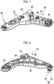
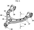
- FIG. 5 is a perspective view of a vehicular hybrid upper arm 100 according to an embodiment.
- FIG. 6 is an exploded perspective view of the vehicular hybrid upper arm 100 according to an embodiment.
- the vehicular hybrid upper arm 100 may include an upper arm body 110 which can be fabricated from a metal material such as steel or aluminum by a general press method.
- the upper arm body 110 may include two leg portions 102 and a joint portion 104 integrally connecting the two leg portions 102.
- a bush pipe 116 may be coupled, by welding, to each of leading end portions of the two leg portions 102.
- a ball joint pipe 118 may be coupled, by welding, to a leading end portion of the joint portion 104.
- Generally semicylindrical coupling holes may be formed at the leading end portion of each of the two leg portions 102 and at the leading end portion of the joint portion 104.
- Each pipe 116, 118 may be fitted in shape to the coupling hole and be coupled, by welding, to the coupling hole.
- the ball joint pipe 118 may be located in a central portion between the bush pipes 116. Further, the bush pipes 116 may be disposed to be opened in the horizontal direction, while the ball joint pipe 118 may be disposed to be opened in the vertical direction. Bushes 130 may be force-fitted into the respective two bush pipes 116. The respective bushes 130 may be fastened to a vehicular body with a bolt or the like.
- a ball joint 140 may be force-fitted into and coupled to the ball joint pipe 118.
- the ball joint 140 may include: a ball stud 142; a ball bearing 141 which surrounds and rotatably supports the ball stud; a dust cover 143 which surrounds the ball stud 142 to prevent intrusion of foreign matters; a ring clip 144 for assembling the dust cover 143 to the ball stud 142; and a protector 45 covered on the ball stud 142.
- a large-diameter hole 107 having a relatively large diameter may be formed through the joint portion 104.
- a plurality of middle-diameter holes 106 and a plurality of small-diameter holes 105, which have a relatively small size, may be disposed in each leg portion 102 with predetermined spacings along a longitudinal direction of the leg portion.
- the middle-diameter holes 106 may be disposed between the small-diameter holes 105.
- the number of the middle-diameter holes 106 and the small-diameter holes 105 may be appropriately adjusted as needed.
- An insert 120 which is injection-molded with a plastic material and is integrally coupled to the upper arm body 110 by injection molding, is provided inside the upper arm body 110.
- a weight of the upper arm body 110 has a weight ratio of 50% or more (at minimum) and 90% or less (at maximum) with respect to the total weight of the hybrid upper arm 100.
- the insert 120 has a shape approximately similar to that of the upper arm body 110. That is, the insert may include two leg portions 122 and a joint portion 124. A large-diameter hole 125 may be formed through the joint portion 124.
- a large-diameter coupling rim 126 which is enlarged in a thickness direction and a radial direction, may be formed at an edge of the large-diameter hole 125 of the joint portion 124.
- the large-diameter coupling rim 126 may be formed to be disposed along a peripheral edge of the large-diameter hole 107 of the upper arm body 110 when the plastic insert 120 is injected.
- the large-diameter coupling rim may increases the coupling force between the upper arm body 110 and the insert 120 such that the insert 120 coupled to the inside of the upper arm body 110 is not separated from the upper arm body 110.
- a plurality of coupling protrusions 127 may be formed in each of the leg portions 122 of the insert 120 at predetermined spacings along a longitudinal direction. When the insert 120 is injected, each of the coupling protrusions 127 may be inserted into and fill in the small-diameter hole 105 formed in each leg portion 102 of the upper arm body 110, and may be formed in a size radially enlarged up to a peripheral edge of the small-diameter hole 105. Each of the coupling protrusions 127 may also improve the coupling force between the upper arm body 110 and the insert 120.
- a middle-diameter coupling rim 123 formed between the two coupling protrusions 127 may be formed so as to be radially enlarged up to a peripheral edge of the middle-diameter hole 106 formed in each leg portion 102 of the upper arm body 110 when the insert 120 is injected.
- the middle-diameter coupling rim 123 may improve the coupling force between the upper arm body 110 and the insert 120.
- FIG. 7 is a perspective view showing an underside of the vehicular hybrid upper arm 100 according to an embodiment.
- at least one reinforcement rib 128 is provided, which may have a generally lattice-patterned shape and may be protrudingly formed integrally with the insert 120.
- FIG. 8 is a sectional view taken along a line A-A in FIG. 5 .
- the upper arm body 110 may include two coupling flanges 103 which are bent inward in a width direction of the upper arm body along edges of the upper arm body.
- the two coupling flanges 103 may be formed to face each other.
- the two coupling flanges 103 may be inserted into the inside of the insert 120 when the insert 120 is injected, thereby improving the coupling force between the upper arm body 110 and the insert 120.
- FIG. 9 is a graph showing maximum loads versus weights in the hybrid suspension arms according to various embodiments.
- the X axis represents the weights (unit: kg) of the hybrid suspension arms, and the Y axis represents the maximum loads (unit: N) which the materials of the hybrid suspension arms can withstand without being buckled.
- the line labeled by "Steel” indicates a case where the suspension arm is entirely made of a steel material
- the line labeled by "'Hybrid” indicates a case where the hybrid suspension arm is comprised of two types of steel and plastic insert according to embodiments.
- the weight can be reduced in comparison with a steel-made suspension arm which can withstand the same maximum load.
- the proportion of the plastic insert exceeds a certain level, i.e., when the proportion of steel is lowered, even if the total weight of the hybrid suspension arm increases, the maximum load which the hybrid suspension arm can withstand may be lowered in comparison with a general steel-made suspension arm.
- the lower arm body 20 or the upper arm body 110 has the weight ratio of 50% or more and 90% or less with respect to the total weight of the hybrid suspension arm. More preferably, the lower arm body 20 or the upper arm body 110 may have the weight ratio of 55% or more and 78% or less with respect to the total weight of the hybrid suspension arm.
Landscapes
- Engineering & Computer Science (AREA)
- Mechanical Engineering (AREA)
- General Engineering & Computer Science (AREA)
- Manufacturing & Machinery (AREA)
- Vehicle Body Suspensions (AREA)
- Injection Moulding Of Plastics Or The Like (AREA)
Claims (8)
- Hybrider oberer Arm (100), umfassend: einen oberen Armkörper (110), der aus einem Metallmaterial hergestellt ist; und einen Einsatz (120), der einstückig mit dem oberen Armkörper (110) spritzgegossen ist, so dass der Einsatz in eine Innenseite des oberen Armkörpers (110) eingesetzt ist, wobei der hybride obere Arm (100) dadurch gekennzeichnet ist, dass:der obere Armkörper (110) ein Gewichtsverhältnis von 50 % oder mehr und 90 % oder weniger in Bezug auf ein Gesamtgewicht des hybriden oberen Arms aufweist,der obere Armkörper (110) eine obere Wand und zwei Seitenwände beinhaltet, die sich von der oberen Wand nach unten erstrecken,der Einsatz (120) aus einem Kunststoffmaterial besteht und den oberen Armkörper (110) trägt,der Einsatz (120) eine obere Wand und zwei Seitenwände beinhaltet, die sich von der oberen Wand des Einsatzes (120) nach unten erstrecken,die obere Wand und die Seitenwände des Einsatzes (120) mit der oberen Wand bzw. den Seitenwänden des oberen Armkörpers (110) verbunden sind,der Einsatz (120) eine Verstärkungsrippe (128) aufweisend eine gitterartig gemusterte Form beinhaltet, die in einem von der oberen Wand und den Seitenwänden des Einsatzes (120) umgebenen Raum angeordnet ist und die obere Wand und die Seitenwände des Einsatzes (120) stützt,beide Enden der Verstärkungsrippe (128) jeweils mit den Seitenwänden des Einsatzes (120) gekoppelt sind und die Seitenwände des Einsatzes (120) miteinander verbinden,eine vertikale Länge der Verstärkungsrippe (128) kleiner ist als die vertikalen Längen der Seitenwände des Einsatzes (120), unddie Verstärkungsrippe (128) Folgendes beinhaltet: einen ersten Bereich aufweisend eine konstante vertikale Länge; und einen zweiten Bereich, der zwischen dem ersten Bereich und den Seitenwänden des Einsatzes (120) angeordnet ist und eine vertikale Länge aufweist, die von dem ersten Bereich zu den Seitenwänden des Einsatzes (120) hin allmählich zunimmt.
- Hybrider oberer Arm (100) gemäß Anspruch 1, wobei ein Kopplungsflansch (130) in dem oberen Armkörper (110) so ausgebildet ist, dass er in einer Breitenrichtung des oberen Armkörpers (110) nach innen gebogen ist, und wobei der Kupplungsflansch (103) in den Einsatz (120) eingesetzt und mit diesem gekoppelt ist.
- Hybrider oberer Arm (100) gemäß Anspruch 1, wobei der obere Armkörper (110) zwei Schenkelbereiche (102) und einen die beiden Schenkelbereiche (102) einstückig verbindenden Verbindungsbereich (104) beinhaltet,wobei ein Buchsenrohr (116) mit einem vorderen Endbereich jedes der beiden Schenkelbereiche (102) durch Schweißen verbunden ist,wobei ein Kugelgelenkrohr (118) durch Schweißen mit einem vorderen Endbereich des Verbindungsbereichs (104) verbunden ist,wobei Buchsen (130) kraftschlüssig in die jeweiligen Buchsenrohre (116) eingepasst und mit diesen gekoppelt sind,wobei ein Kugelgelenk (140) kraftschlüssig in das Kugelgelenkrohr (130) eingepasst und mit diesem gekoppelt ist,wobei das Kugelgelenkrohr (118) in einem zentralen Bereich zwischen den Buchsenrohren (H6) angeordnet ist,wobei die Buchsenrohre (116) so angeordnet sind, dass sie in einer horizontalen Richtung geöffnet werden können, und wobei das Kugelgelenkrohr (118) so angeordnet ist, dass es in einer vertikalen Richtung geöffnet werden kann.
- Hybrider oberer Arm (100) gemäß Anspruch 1, wobei mindestens ein Loch (105, 106, 107) durch den oberen Armkörper (110) ausgebildet ist, und
wobei mindestens ein Kupplungsvorsprung (127) in dem Einsatz (120) ausgebildet ist, wobei der mindestens eine Kupplungsvorsprung in das Loch (105, 106, 107) eingesetzt ist und dieses ausfüllt und bis zu einem Umfangsrand des Lochs (105, 106, 107) vergrößert ist. - Hybrider oberer Arm (100) gemäß Anspruch 4, wobei der obere Armkörper (110) zwei Schenkelbereiche (102) und einen Gelenkbereich (104) beinhaltet, der die beiden Schenkelbereiche (102) einstückig verbindet,wobei der Einsatz (120) zwei Schenkelbereiche (122) und einen die beiden Schenkelbereiche einstückig verbindenden Gelenkbereich (124) beinhaltet,wobei das mindestens eine Loch (105, 106, 107) mindestens ein Loch mit kleinem Durchmesser (105) aufweist, das in jedem der beiden Schenkelbereiche (102) in vorbestimmten Abständen entlang der Längsrichtungen angeordnet ist, undwobei der mindestens eine Kupplungsvorsprung (127) in das mindestens eine Loch mit kleinem Durchmesser (105) eingesetzt ist und dieses ausfüllt und in einer Größe ausgebildet ist, die radial bis zu einem Umfangsrand des mindestens einen Lochs mit kleinem Durchmesser (105) vergrößert ist.
- Hybrider oberer Arm (100) gemäß Anspruch 5, wobei das mindestens eine Loch mit kleinem Durchmesser (105) zwei oder mehr Löcher mit kleinem Durchmesser beinhaltet, die nebeneinander angeordnet sind,wobei mindestens ein Loch mit mittlerem Durchmesser (106), das einen relativ größeren Durchmesser als das Loch mit kleinem Durchmesser (105) aufweist, zwischen den zwei oder mehr Löchern mit kleinem Durchmesser (105) ausgebildet ist, undwobei ein Bereich des Einsatzes (120) in das Loch mit mittlerem Durchmesser (106) eingesetzt wird, so dass ein Kupplungsrand (123) mit mittlerem Durchmesser, der radial bis zu einem Umfangsrand des Lochs mit mittlerem Durchmesser (106) vergrößert ist, in dem Einsatz (120) ausgebildet ist.
- Hybrider oberer Arm (100) gemäß Anspruch 4, wobei das mindestens eine Loch (105, 106, 107) ein Loch mit großem Durchmesser (107) beinhaltet, das in dem Verbindungsbereich (104) des oberen Armkörpers (110) ausgebildet ist, und
wobei ein Teil des Einsatzes (120) in das Loch mit großem Durchmesser (107) eingesetzt ist, so dass ein Kupplungsrand (126) mit großem Durchmesser, der radial bis zu einem Umfangsrand des Lochs mit großem Durchmesser (107) vergrößert ist, in dem Einsatz (120) ausgebildet ist. - Hybrider oberer Arm (100) gemäß Anspruch 1, wobei die Verstärkungsrippe (128) mit einer gitterartig gemusterten Form einstückig mit dem Einsatz (120) vorspringend ausgebildet ist.
Applications Claiming Priority (3)
| Application Number | Priority Date | Filing Date | Title |
|---|---|---|---|
| KR20150189881 | 2015-12-30 | ||
| KR1020160145447A KR101826825B1 (ko) | 2015-12-30 | 2016-11-02 | 하이브리드 현가암 |
| PCT/KR2016/015513 WO2017116183A2 (ko) | 2015-12-30 | 2016-12-29 | 하이브리드 현가암 |
Publications (3)
| Publication Number | Publication Date |
|---|---|
| EP3398796A2 EP3398796A2 (de) | 2018-11-07 |
| EP3398796A4 EP3398796A4 (de) | 2019-09-04 |
| EP3398796B1 true EP3398796B1 (de) | 2025-03-05 |
Family
ID=59217861
Family Applications (2)
| Application Number | Title | Priority Date | Filing Date |
|---|---|---|---|
| EP16882134.6A Active EP3398795B1 (de) | 2015-12-30 | 2016-12-29 | Hybrid-fahrwekslenker für ein fahrzeug |
| EP16882135.3A Active EP3398796B1 (de) | 2015-12-30 | 2016-12-29 | Hybrid-fahrwerkslenker |
Family Applications Before (1)
| Application Number | Title | Priority Date | Filing Date |
|---|---|---|---|
| EP16882134.6A Active EP3398795B1 (de) | 2015-12-30 | 2016-12-29 | Hybrid-fahrwekslenker für ein fahrzeug |
Country Status (6)
| Country | Link |
|---|---|
| US (2) | US10814535B2 (de) |
| EP (2) | EP3398795B1 (de) |
| JP (2) | JP6706325B2 (de) |
| KR (3) | KR101792136B1 (de) |
| CN (2) | CN108473013B (de) |
| WO (1) | WO2017115932A1 (de) |
Families Citing this family (36)
| Publication number | Priority date | Publication date | Assignee | Title |
|---|---|---|---|---|
| WO2016167151A1 (ja) * | 2015-04-13 | 2016-10-20 | 株式会社エフテック | 車両用サスペンションアーム |
| WO2017115932A1 (ko) * | 2015-12-30 | 2017-07-06 | 주식회사 일진 | 차량용 하이브리드 현가암 및 그 제조방법 |
| KR101815147B1 (ko) * | 2016-02-04 | 2018-01-31 | 주식회사 일진 | 볼 조인트 및 그 제작방법 |
| KR101792137B1 (ko) * | 2016-12-27 | 2017-11-02 | 주식회사 일진 | 차량용 하이브리드 현가암 |
| DE102017212746B4 (de) * | 2017-07-25 | 2025-04-24 | Ford Global Technologies, Llc | Hybridlenker einer Radaufhängung mit integrierter Federfunktion |
| DE102017213563A1 (de) * | 2017-08-04 | 2019-02-07 | Zf Friedrichshafen Ag | Dreipunktlenker und Herstellungsverfahren für einen Dreipunktlenker |
| KR101958433B1 (ko) * | 2017-08-18 | 2019-03-20 | 주식회사 일진 | 볼 조인트 및 이를 포함하는 하이브리드 현가암 |
| KR101935415B1 (ko) * | 2017-09-29 | 2019-01-07 | 주식회사 일진 | 고정 핀을 이용한 차량용 하이브리드 현가암의 제조 방법 및 이를 이용하여 제조한 하이브리드 현가암 |
| KR20190072712A (ko) | 2017-12-15 | 2019-06-26 | 서진산업 주식회사 | 강성보강 플랜지와 사출구조를 갖는 하이브리드 로워암 |
| DE102018206417A1 (de) * | 2018-04-25 | 2019-10-31 | Bayerische Motoren Werke Aktiengesellschaft | Radaufhängung für ein Kraftfahrzeug |
| KR102063065B1 (ko) * | 2018-05-28 | 2020-02-11 | (주)화신 | 차량용 로어암 |
| KR102084257B1 (ko) * | 2018-06-26 | 2020-03-04 | 주식회사 일진 | 볼 조인트, 이를 포함하는 현가 암 및 이의 제조 방법 |
| JP2020001501A (ja) * | 2018-06-27 | 2020-01-09 | 株式会社神戸製鋼所 | 車両用サスペンション部材 |
| KR20200047193A (ko) * | 2018-10-26 | 2020-05-07 | 주식회사 일진 | 하이브리드 암 제조에 사용되는 삽입 장치 및 이를 포함하는 하이브리드 암 |
| CN109606044A (zh) * | 2018-12-28 | 2019-04-12 | 安徽科源机械有限公司 | 一种汽车下摆臂总成 |
| KR102607438B1 (ko) * | 2019-01-25 | 2023-11-29 | 주식회사 일진 | 차량용 현가암 |
| DE102019203832A1 (de) * | 2019-03-20 | 2020-09-24 | Audi Ag | Radführungslenker für ein Fahrwerk eines Fahrzeugs, insbesondere eines Kraftfahrzeugs, sowie Fahrzeug, insbesondere Kraftfahrzeug |
| DE102019204486A1 (de) * | 2019-03-29 | 2020-10-01 | Zf Friedrichshafen Ag | Lenker für ein Fahrwerk eines Kraftfahrzeugs |
| KR102145307B1 (ko) * | 2019-04-25 | 2020-08-18 | 주식회사 센트랄 | 차량용 링크 |
| EP3996942B1 (de) * | 2019-07-08 | 2024-06-12 | Tiberina Solutions S.r.l. | Hybrider aufhängungsarm |
| JP7044099B2 (ja) * | 2019-07-09 | 2022-03-30 | Jfeスチール株式会社 | サスペンションアーム |
| DE102019122721B4 (de) * | 2019-08-23 | 2025-01-02 | Benteler Automobiltechnik Gmbh | Fahrwerklenker und Verfahren zur Herstellung eines Fahrwerklenkers |
| KR20210033354A (ko) * | 2019-09-18 | 2021-03-26 | 주식회사 일진 | 차량용 현가암 및 이의 제조방법 |
| JP2021088254A (ja) * | 2019-12-04 | 2021-06-10 | 日軽金アクト株式会社 | 自動車用足回り部品 |
| KR102326467B1 (ko) * | 2019-12-20 | 2021-11-16 | (주)동희산업 | 트레일링 암의 제조방법 및 이를 이용하여 제조되는 트레일링 암 |
| KR102339940B1 (ko) * | 2019-12-27 | 2021-12-17 | 주식회사 일진 | 차량용 현가암 |
| CN111731058B (zh) * | 2020-06-04 | 2021-06-22 | 索密克汽车配件有限公司 | 一种增强拉脱力的汽车摆臂 |
| CN111823799B (zh) * | 2020-07-22 | 2022-01-28 | 中国第一汽车股份有限公司 | 一种复合材料控制臂及其制备方法 |
| JP2022146559A (ja) * | 2021-03-22 | 2022-10-05 | 本田技研工業株式会社 | トレーリングアーム |
| US12187093B1 (en) | 2023-06-27 | 2025-01-07 | RB Distribution, Inc. | Control arm and adjustable ball joint |
| US12122211B1 (en) | 2023-06-27 | 2024-10-22 | RB Distribution, Inc. | Adjustable control arm and ball joint assembly |
| CN116766845A (zh) * | 2023-07-13 | 2023-09-19 | 重庆长安汽车股份有限公司 | 一种悬架上控制臂总成、悬架总成和车辆 |
| KR102623037B1 (ko) * | 2023-07-19 | 2024-01-10 | 주식회사 씨티알 | 차량용 하이브리드 컨트롤 암 |
| KR102623025B1 (ko) * | 2023-07-19 | 2024-01-10 | 주식회사 씨티알 | 차량용 하이브리드 컨트롤 암 |
| KR102623016B1 (ko) * | 2023-07-19 | 2024-01-10 | 주식회사 씨티알 | 차량용 하이브리드 컨트롤 암 |
| JP2025074848A (ja) * | 2023-10-30 | 2025-05-14 | トヨタ自動車株式会社 | サスペンション構造の構成部品 |
Family Cites Families (48)
| Publication number | Priority date | Publication date | Assignee | Title |
|---|---|---|---|---|
| JPH0747826A (ja) | 1993-08-06 | 1995-02-21 | Toyota Motor Corp | サスペンションアーム及びその製造方法 |
| JPH07251617A (ja) | 1994-03-15 | 1995-10-03 | Nissan Motor Co Ltd | 車両用サスペンション |
| JP3127764B2 (ja) * | 1995-01-22 | 2001-01-29 | 三菱自動車工業株式会社 | 自動車の後輪サスペンションアーム |
| JPH08318722A (ja) * | 1995-03-23 | 1996-12-03 | Toyota Motor Corp | サスペンションアーム |
| JPH08312636A (ja) * | 1995-05-15 | 1996-11-26 | Hitachi Metals Ltd | サスペンション部品 |
| JP3191654B2 (ja) * | 1995-08-30 | 2001-07-23 | トヨタ自動車株式会社 | サスペンションアーム |
| JPH11115800A (ja) * | 1997-10-08 | 1999-04-27 | Marugo Rubber Ind Co Ltd | 防振装置 |
| IT1320526B1 (it) * | 2000-07-07 | 2003-12-10 | Fiat Ricerche | Giunto di interconnessione di elementi strutturali. |
| JP3725031B2 (ja) | 2001-01-12 | 2005-12-07 | 本田技研工業株式会社 | サスペンションアーム |
| ITTO20010253A1 (it) * | 2001-03-16 | 2002-09-16 | Sistemi Sospensioni Spa | Elemento strutturale per una sospensione di un autoveicolo e procedimento per la sua realizzazione. |
| KR20030088238A (ko) | 2002-05-13 | 2003-11-19 | 현대자동차주식회사 | 차량용 현가장치의 로워아암 구조 |
| KR20050038139A (ko) * | 2003-10-21 | 2005-04-27 | 기아자동차주식회사 | 자동차의 로어암 부시 장치 |
| DE102005004917B4 (de) * | 2005-02-02 | 2013-02-28 | Benteler Automobiltechnik Gmbh | Lenkerbauteil für Radaufhängungen von Kraftfahrzeugen und Verfahren zu seiner Herstellung |
| US7393152B2 (en) * | 2005-09-20 | 2008-07-01 | Federal Mogul World Wide, Inc. | Cone adaptor for ball joint studs, tie rods, sway bar links and the like |
| KR100834249B1 (ko) * | 2007-02-07 | 2008-05-30 | 위아 주식회사 | 강도가 보강된 경량화 로어암 |
| DE102007015615B4 (de) * | 2007-03-29 | 2012-07-19 | Zf Friedrichshafen Ag | Verbindungsstück zum gelenkigen Verbinden von im Fahrwerk eines Fahrzeugs angeordneten Bauelementen |
| DE102007015616B4 (de) | 2007-03-29 | 2021-10-21 | Zf Friedrichshafen Ag | Verbindungsstück zum gelenkigen Verbinden von im Fahrwerk eines Fahrzeugs angeordneten Bauelementen |
| DE102007047191A1 (de) * | 2007-07-03 | 2009-01-08 | Hyundai Motor Company | Unterer Arm einer Fahrzeugaufhängung |
| JP5141961B2 (ja) * | 2008-03-26 | 2013-02-13 | マツダ株式会社 | 車両のサスペンションサブフレーム構造 |
| CN201362147Y (zh) * | 2009-03-23 | 2009-12-16 | 上海采埃孚伦福德底盘技术有限公司 | 铝合金转向系统控制臂 |
| KR20100112846A (ko) | 2009-04-10 | 2010-10-20 | 주식회사 일진 | 스태빌라이저 링크 및 그 제작 방법 |
| KR20100116081A (ko) | 2009-04-21 | 2010-10-29 | 주식회사 일진 | 차량의 콘트롤암 및 그 제조 방법 |
| CN201511770U (zh) * | 2009-09-10 | 2010-06-23 | 比亚迪股份有限公司 | 一种悬架臂 |
| KR101180942B1 (ko) | 2009-12-04 | 2012-09-07 | 현대자동차주식회사 | 서스펜션 암 |
| KR20110063164A (ko) | 2009-12-04 | 2011-06-10 | 현대자동차주식회사 | 서스펜션 암 |
| JP2011116340A (ja) * | 2009-12-04 | 2011-06-16 | Hyundai Motor Co Ltd | サスペンションアーム及びサスペンションアームの製作方法 |
| KR20110063166A (ko) | 2009-12-04 | 2011-06-10 | 현대자동차주식회사 | 서스펜션 암 |
| DE102009054999A1 (de) | 2009-12-18 | 2011-06-22 | Henkel AG & Co. KGaA, 40589 | Verbundbauteil |
| IT1400618B1 (it) * | 2010-05-12 | 2013-06-14 | Sistemi Sospensioni Spa | Elemento strutturale in materiale composito, particolarmente per sospensione di veicolo |
| KR20120003176U (ko) * | 2010-10-29 | 2012-05-09 | 주식회사 동희산업 | 차량용 로워 암 |
| KR101211419B1 (ko) | 2010-10-29 | 2012-12-12 | 주식회사화신 | 자동차용 로워암 |
| DE102011003971A1 (de) * | 2011-02-11 | 2012-08-16 | Zf Friedrichshafen Ag | Faserverbund-Hybridlenker |
| KR101302328B1 (ko) | 2011-10-05 | 2013-08-30 | 한국지엠 주식회사 | 전방 현가 장치의 로어 컨트롤 암 조립체 |
| JP5905490B2 (ja) * | 2011-12-21 | 2016-04-20 | 本田技研工業株式会社 | サスペンションアーム取付構造 |
| JP5468644B2 (ja) * | 2012-06-15 | 2014-04-09 | 日本発條株式会社 | スタビリンク |
| KR101393849B1 (ko) * | 2012-12-12 | 2014-05-12 | 현대자동차주식회사 | 차량용 로어암 |
| EP2759423B1 (de) * | 2013-01-28 | 2015-04-22 | Gestamp Umformtechnik GmbH | Querlenker aus faserverstärktem Kunststoff für eine Radaufhängung eines Fahrzeuges |
| DE102013214673A1 (de) * | 2013-07-26 | 2015-01-29 | Bayerische Motoren Werke Aktiengesellschaft | Radführender Lenker aus faserverstärktem thermoplastischen Werkstoff |
| US9327570B2 (en) * | 2014-03-04 | 2016-05-03 | Federal-Mogul Motorparts Corporation | Ball joint assembly for a control arm |
| EP2927029B1 (de) * | 2014-04-02 | 2018-06-13 | Autotech Engineering Deutschland GmbH | Verfahren zum Herstellen eines Fahrwerklenkers |
| KR101549917B1 (ko) * | 2014-07-10 | 2015-09-03 | 주식회사 일진 | 차량의 현가암 및 그 제조방법 |
| KR101573397B1 (ko) * | 2014-08-01 | 2015-12-01 | 주식회사 일진 | 볼 조인트 어셈블리 및 그 제조방법 |
| KR101732063B1 (ko) * | 2015-04-29 | 2017-05-08 | 주식회사 일진 | 볼 조인트 일체형 자동차용 하이브리드 암 및 그 제조 방법 |
| KR101732066B1 (ko) | 2015-04-29 | 2017-05-08 | 주식회사 일진 | 치핑에 의한 도장면 손상 방지 구조를 가지는 하이브리드 암 |
| WO2017115932A1 (ko) * | 2015-12-30 | 2017-07-06 | 주식회사 일진 | 차량용 하이브리드 현가암 및 그 제조방법 |
| KR101792137B1 (ko) * | 2016-12-27 | 2017-11-02 | 주식회사 일진 | 차량용 하이브리드 현가암 |
| KR101857172B1 (ko) * | 2016-12-28 | 2018-05-16 | 주식회사 일진 | 차량용 하이브리드 현가암 및 그 제조방법 |
| DE102017212746B4 (de) * | 2017-07-25 | 2025-04-24 | Ford Global Technologies, Llc | Hybridlenker einer Radaufhängung mit integrierter Federfunktion |
-
2016
- 2016-04-06 WO PCT/KR2016/003569 patent/WO2017115932A1/ko not_active Ceased
- 2016-11-02 KR KR1020160145446A patent/KR101792136B1/ko active Active
- 2016-11-02 KR KR1020160145447A patent/KR101826825B1/ko active Active
- 2016-12-09 KR KR1020160167842A patent/KR101747336B1/ko active Active
- 2016-12-29 US US16/066,942 patent/US10814535B2/en active Active
- 2016-12-29 US US16/066,930 patent/US10953577B2/en active Active
- 2016-12-29 EP EP16882134.6A patent/EP3398795B1/de active Active
- 2016-12-29 CN CN201680076789.6A patent/CN108473013B/zh active Active
- 2016-12-29 EP EP16882135.3A patent/EP3398796B1/de active Active
- 2016-12-29 CN CN201680076790.9A patent/CN108473014B/zh active Active
- 2016-12-29 JP JP2018534584A patent/JP6706325B2/ja active Active
- 2016-12-29 JP JP2018534583A patent/JP6860577B2/ja active Active
Also Published As
| Publication number | Publication date |
|---|---|
| JP6706325B2 (ja) | 2020-06-03 |
| EP3398796A4 (de) | 2019-09-04 |
| KR20170080449A (ko) | 2017-07-10 |
| CN108473013B (zh) | 2022-06-14 |
| US10814535B2 (en) | 2020-10-27 |
| EP3398795B1 (de) | 2025-02-26 |
| KR101826825B1 (ko) | 2018-02-08 |
| US20190118437A1 (en) | 2019-04-25 |
| EP3398795A2 (de) | 2018-11-07 |
| EP3398796A2 (de) | 2018-11-07 |
| US10953577B2 (en) | 2021-03-23 |
| KR101747336B1 (ko) | 2017-06-14 |
| KR101792136B1 (ko) | 2017-11-02 |
| JP6860577B2 (ja) | 2021-04-14 |
| JP2019500274A (ja) | 2019-01-10 |
| CN108473014A (zh) | 2018-08-31 |
| JP2019506328A (ja) | 2019-03-07 |
| EP3398795A4 (de) | 2019-09-04 |
| CN108473014B (zh) | 2021-08-17 |
| CN108473013A (zh) | 2018-08-31 |
| US20190061452A1 (en) | 2019-02-28 |
| KR20170080448A (ko) | 2017-07-10 |
| WO2017115932A1 (ko) | 2017-07-06 |
Similar Documents
| Publication | Publication Date | Title |
|---|---|---|
| EP3398796B1 (de) | Hybrid-fahrwerkslenker | |
| US10442262B2 (en) | Hybrid arm and method of manufacturing same | |
| JP6771847B2 (ja) | 車両用ハイブリッドサスペンションアーム | |
| CN103338949B (zh) | 单壳式弹簧导杆 | |
| US11104196B2 (en) | Method for manufacturing hybrid suspension arm for vehicle using fixing pin and hybrid suspension arm manufactured by using same | |
| US11491837B2 (en) | Suspension arm and ball joint | |
| US9649905B2 (en) | Shock absorber | |
| JP2011116336A (ja) | サスペンションアーム | |
| CN115892246B (zh) | 车身后地板结构及具有其的车辆 | |
| KR101450755B1 (ko) | 자동차 현가장치용 마운팅 브라켓 | |
| US12188515B2 (en) | Ball joint, suspension arm comprising same, and manufacturing method thereof | |
| KR102074495B1 (ko) | 차량용 너클 어셈블리 및 그 제조 방법 | |
| KR102529385B1 (ko) | 서브 프레임 마운팅구조 | |
| KR20170119235A (ko) | 하이브리드 현가암 | |
| KR102264730B1 (ko) | 쇽업소버 마운트의 제조방법 및 쇽업소버 마운트 | |
| KR102607438B1 (ko) | 차량용 현가암 | |
| KR20210090524A (ko) | 차량용 현가암 및 이의 제조방법 |
Legal Events
| Date | Code | Title | Description |
|---|---|---|---|
| STAA | Information on the status of an ep patent application or granted ep patent |
Free format text: STATUS: THE INTERNATIONAL PUBLICATION HAS BEEN MADE |
|
| PUAI | Public reference made under article 153(3) epc to a published international application that has entered the european phase |
Free format text: ORIGINAL CODE: 0009012 |
|
| STAA | Information on the status of an ep patent application or granted ep patent |
Free format text: STATUS: REQUEST FOR EXAMINATION WAS MADE |
|
| 17P | Request for examination filed |
Effective date: 20180730 |
|
| AK | Designated contracting states |
Kind code of ref document: A2 Designated state(s): AL AT BE BG CH CY CZ DE DK EE ES FI FR GB GR HR HU IE IS IT LI LT LU LV MC MK MT NL NO PL PT RO RS SE SI SK SM TR |
|
| AX | Request for extension of the european patent |
Extension state: BA ME |
|
| DAV | Request for validation of the european patent (deleted) | ||
| DAX | Request for extension of the european patent (deleted) | ||
| A4 | Supplementary search report drawn up and despatched |
Effective date: 20190806 |
|
| RIC1 | Information provided on ipc code assigned before grant |
Ipc: B29C 45/14 20060101ALI20190731BHEP Ipc: B29L 31/30 20060101ALI20190731BHEP Ipc: B60G 7/00 20060101AFI20190731BHEP Ipc: F16C 11/06 20060101ALI20190731BHEP |
|
| STAA | Information on the status of an ep patent application or granted ep patent |
Free format text: STATUS: EXAMINATION IS IN PROGRESS |
|
| 17Q | First examination report despatched |
Effective date: 20211223 |
|
| GRAP | Despatch of communication of intention to grant a patent |
Free format text: ORIGINAL CODE: EPIDOSNIGR1 |
|
| STAA | Information on the status of an ep patent application or granted ep patent |
Free format text: STATUS: GRANT OF PATENT IS INTENDED |
|
| INTG | Intention to grant announced |
Effective date: 20240926 |
|
| GRAS | Grant fee paid |
Free format text: ORIGINAL CODE: EPIDOSNIGR3 |
|
| GRAA | (expected) grant |
Free format text: ORIGINAL CODE: 0009210 |
|
| STAA | Information on the status of an ep patent application or granted ep patent |
Free format text: STATUS: THE PATENT HAS BEEN GRANTED |
|
| AK | Designated contracting states |
Kind code of ref document: B1 Designated state(s): AL AT BE BG CH CY CZ DE DK EE ES FI FR GB GR HR HU IE IS IT LI LT LU LV MC MK MT NL NO PL PT RO RS SE SI SK SM TR |
|
| REG | Reference to a national code |
Ref country code: GB Ref legal event code: FG4D |
|
| REG | Reference to a national code |
Ref country code: CH Ref legal event code: EP |
|
| REG | Reference to a national code |
Ref country code: DE Ref legal event code: R096 Ref document number: 602016091479 Country of ref document: DE |
|
| REG | Reference to a national code |
Ref country code: IE Ref legal event code: FG4D |
|
| PG25 | Lapsed in a contracting state [announced via postgrant information from national office to epo] |
Ref country code: RS Free format text: LAPSE BECAUSE OF FAILURE TO SUBMIT A TRANSLATION OF THE DESCRIPTION OR TO PAY THE FEE WITHIN THE PRESCRIBED TIME-LIMIT Effective date: 20250605 |
|
| PG25 | Lapsed in a contracting state [announced via postgrant information from national office to epo] |
Ref country code: FI Free format text: LAPSE BECAUSE OF FAILURE TO SUBMIT A TRANSLATION OF THE DESCRIPTION OR TO PAY THE FEE WITHIN THE PRESCRIBED TIME-LIMIT Effective date: 20250305 |
|
| REG | Reference to a national code |
Ref country code: NL Ref legal event code: MP Effective date: 20250305 |
|
| PG25 | Lapsed in a contracting state [announced via postgrant information from national office to epo] |
Ref country code: ES Free format text: LAPSE BECAUSE OF FAILURE TO SUBMIT A TRANSLATION OF THE DESCRIPTION OR TO PAY THE FEE WITHIN THE PRESCRIBED TIME-LIMIT Effective date: 20250305 |
|
| REG | Reference to a national code |
Ref country code: LT Ref legal event code: MG9D |
|
| PG25 | Lapsed in a contracting state [announced via postgrant information from national office to epo] |
Ref country code: NO Free format text: LAPSE BECAUSE OF FAILURE TO SUBMIT A TRANSLATION OF THE DESCRIPTION OR TO PAY THE FEE WITHIN THE PRESCRIBED TIME-LIMIT Effective date: 20250605 |
|
| PG25 | Lapsed in a contracting state [announced via postgrant information from national office to epo] |
Ref country code: HR Free format text: LAPSE BECAUSE OF FAILURE TO SUBMIT A TRANSLATION OF THE DESCRIPTION OR TO PAY THE FEE WITHIN THE PRESCRIBED TIME-LIMIT Effective date: 20250305 |
|
| PG25 | Lapsed in a contracting state [announced via postgrant information from national office to epo] |
Ref country code: LV Free format text: LAPSE BECAUSE OF FAILURE TO SUBMIT A TRANSLATION OF THE DESCRIPTION OR TO PAY THE FEE WITHIN THE PRESCRIBED TIME-LIMIT Effective date: 20250305 |
|
| PG25 | Lapsed in a contracting state [announced via postgrant information from national office to epo] |
Ref country code: GR Free format text: LAPSE BECAUSE OF FAILURE TO SUBMIT A TRANSLATION OF THE DESCRIPTION OR TO PAY THE FEE WITHIN THE PRESCRIBED TIME-LIMIT Effective date: 20250606 Ref country code: BG Free format text: LAPSE BECAUSE OF FAILURE TO SUBMIT A TRANSLATION OF THE DESCRIPTION OR TO PAY THE FEE WITHIN THE PRESCRIBED TIME-LIMIT Effective date: 20250305 |
|
| REG | Reference to a national code |
Ref country code: AT Ref legal event code: MK05 Ref document number: 1772627 Country of ref document: AT Kind code of ref document: T Effective date: 20250305 |
|
| PG25 | Lapsed in a contracting state [announced via postgrant information from national office to epo] |
Ref country code: NL Free format text: LAPSE BECAUSE OF FAILURE TO SUBMIT A TRANSLATION OF THE DESCRIPTION OR TO PAY THE FEE WITHIN THE PRESCRIBED TIME-LIMIT Effective date: 20250305 |
|
| PG25 | Lapsed in a contracting state [announced via postgrant information from national office to epo] |
Ref country code: SE Free format text: LAPSE BECAUSE OF FAILURE TO SUBMIT A TRANSLATION OF THE DESCRIPTION OR TO PAY THE FEE WITHIN THE PRESCRIBED TIME-LIMIT Effective date: 20250305 |
|
| PG25 | Lapsed in a contracting state [announced via postgrant information from national office to epo] |
Ref country code: SM Free format text: LAPSE BECAUSE OF FAILURE TO SUBMIT A TRANSLATION OF THE DESCRIPTION OR TO PAY THE FEE WITHIN THE PRESCRIBED TIME-LIMIT Effective date: 20250305 |
|
| PG25 | Lapsed in a contracting state [announced via postgrant information from national office to epo] |
Ref country code: PT Free format text: LAPSE BECAUSE OF FAILURE TO SUBMIT A TRANSLATION OF THE DESCRIPTION OR TO PAY THE FEE WITHIN THE PRESCRIBED TIME-LIMIT Effective date: 20250707 |
|
| PG25 | Lapsed in a contracting state [announced via postgrant information from national office to epo] |
Ref country code: PL Free format text: LAPSE BECAUSE OF FAILURE TO SUBMIT A TRANSLATION OF THE DESCRIPTION OR TO PAY THE FEE WITHIN THE PRESCRIBED TIME-LIMIT Effective date: 20250305 Ref country code: IT Free format text: LAPSE BECAUSE OF FAILURE TO SUBMIT A TRANSLATION OF THE DESCRIPTION OR TO PAY THE FEE WITHIN THE PRESCRIBED TIME-LIMIT Effective date: 20250305 |
|
| PG25 | Lapsed in a contracting state [announced via postgrant information from national office to epo] |
Ref country code: AT Free format text: LAPSE BECAUSE OF FAILURE TO SUBMIT A TRANSLATION OF THE DESCRIPTION OR TO PAY THE FEE WITHIN THE PRESCRIBED TIME-LIMIT Effective date: 20250305 |
|
| PG25 | Lapsed in a contracting state [announced via postgrant information from national office to epo] |
Ref country code: EE Free format text: LAPSE BECAUSE OF FAILURE TO SUBMIT A TRANSLATION OF THE DESCRIPTION OR TO PAY THE FEE WITHIN THE PRESCRIBED TIME-LIMIT Effective date: 20250305 Ref country code: CZ Free format text: LAPSE BECAUSE OF FAILURE TO SUBMIT A TRANSLATION OF THE DESCRIPTION OR TO PAY THE FEE WITHIN THE PRESCRIBED TIME-LIMIT Effective date: 20250305 |
|
| PG25 | Lapsed in a contracting state [announced via postgrant information from national office to epo] |
Ref country code: RO Free format text: LAPSE BECAUSE OF FAILURE TO SUBMIT A TRANSLATION OF THE DESCRIPTION OR TO PAY THE FEE WITHIN THE PRESCRIBED TIME-LIMIT Effective date: 20250305 |
|
| PG25 | Lapsed in a contracting state [announced via postgrant information from national office to epo] |
Ref country code: SK Free format text: LAPSE BECAUSE OF FAILURE TO SUBMIT A TRANSLATION OF THE DESCRIPTION OR TO PAY THE FEE WITHIN THE PRESCRIBED TIME-LIMIT Effective date: 20250305 |
|
| PG25 | Lapsed in a contracting state [announced via postgrant information from national office to epo] |
Ref country code: IS Free format text: LAPSE BECAUSE OF FAILURE TO SUBMIT A TRANSLATION OF THE DESCRIPTION OR TO PAY THE FEE WITHIN THE PRESCRIBED TIME-LIMIT Effective date: 20250705 |
|
| REG | Reference to a national code |
Ref country code: DE Ref legal event code: R097 Ref document number: 602016091479 Country of ref document: DE |
|
| PLBE | No opposition filed within time limit |
Free format text: ORIGINAL CODE: 0009261 |
|
| STAA | Information on the status of an ep patent application or granted ep patent |
Free format text: STATUS: NO OPPOSITION FILED WITHIN TIME LIMIT |
|
| PG25 | Lapsed in a contracting state [announced via postgrant information from national office to epo] |
Ref country code: DK Free format text: LAPSE BECAUSE OF FAILURE TO SUBMIT A TRANSLATION OF THE DESCRIPTION OR TO PAY THE FEE WITHIN THE PRESCRIBED TIME-LIMIT Effective date: 20250305 |
|
| REG | Reference to a national code |
Ref country code: CH Ref legal event code: L10 Free format text: ST27 STATUS EVENT CODE: U-0-0-L10-L00 (AS PROVIDED BY THE NATIONAL OFFICE) Effective date: 20260114 |
|
| 26N | No opposition filed |
Effective date: 20251208 |