EP3038112B1 - Fuel assembly - Google Patents
Fuel assembly Download PDFInfo
- Publication number
- EP3038112B1 EP3038112B1 EP16154148.7A EP16154148A EP3038112B1 EP 3038112 B1 EP3038112 B1 EP 3038112B1 EP 16154148 A EP16154148 A EP 16154148A EP 3038112 B1 EP3038112 B1 EP 3038112B1
- Authority
- EP
- European Patent Office
- Prior art keywords
- fuel
- elements
- assembly
- metal
- elongated
- Prior art date
- Legal status (The legal status is an assumption and is not a legal conclusion. Google has not performed a legal analysis and makes no representation as to the accuracy of the status listed.)
- Active
Links
- 239000000446 fuel Substances 0.000 title claims description 641
- 239000000463 material Substances 0.000 claims description 79
- 229910052751 metal Inorganic materials 0.000 claims description 45
- 239000002184 metal Substances 0.000 claims description 45
- 238000005253 cladding Methods 0.000 claims description 38
- 239000002826 coolant Substances 0.000 claims description 33
- 239000002574 poison Substances 0.000 claims description 29
- 231100000614 poison Toxicity 0.000 claims description 29
- WZECUPJJEIXUKY-UHFFFAOYSA-N [O-2].[O-2].[O-2].[U+6] Chemical compound [O-2].[O-2].[O-2].[U+6] WZECUPJJEIXUKY-UHFFFAOYSA-N 0.000 claims description 20
- 229910000439 uranium oxide Inorganic materials 0.000 claims description 20
- 229910052770 Uranium Inorganic materials 0.000 claims description 19
- 239000000956 alloy Substances 0.000 claims description 19
- 239000003870 refractory metal Substances 0.000 claims description 19
- JFALSRSLKYAFGM-UHFFFAOYSA-N uranium(0) Chemical compound [U] JFALSRSLKYAFGM-UHFFFAOYSA-N 0.000 claims description 19
- 229910045601 alloy Inorganic materials 0.000 claims description 18
- XLYOFNOQVPJJNP-ZSJDYOACSA-N Heavy water Chemical group [2H]O[2H] XLYOFNOQVPJJNP-ZSJDYOACSA-N 0.000 claims description 16
- 238000000034 method Methods 0.000 claims description 16
- 238000013461 design Methods 0.000 claims description 15
- QCWXUUIWCKQGHC-UHFFFAOYSA-N Zirconium Chemical compound [Zr] QCWXUUIWCKQGHC-UHFFFAOYSA-N 0.000 claims description 13
- 229910052726 zirconium Inorganic materials 0.000 claims description 13
- 229910052778 Plutonium Inorganic materials 0.000 claims description 12
- OYEHPCDNVJXUIW-UHFFFAOYSA-N plutonium atom Chemical compound [Pu] OYEHPCDNVJXUIW-UHFFFAOYSA-N 0.000 claims description 12
- JFALSRSLKYAFGM-OIOBTWANSA-N uranium-235 Chemical compound [235U] JFALSRSLKYAFGM-OIOBTWANSA-N 0.000 claims description 10
- 238000001125 extrusion Methods 0.000 claims description 9
- 238000004519 manufacturing process Methods 0.000 claims description 8
- ZSLUVFAKFWKJRC-IGMARMGPSA-N 232Th Chemical compound [232Th] ZSLUVFAKFWKJRC-IGMARMGPSA-N 0.000 claims description 7
- 229910052776 Thorium Inorganic materials 0.000 claims description 7
- 239000000919 ceramic Substances 0.000 claims description 7
- 239000011159 matrix material Substances 0.000 claims description 7
- 230000004323 axial length Effects 0.000 claims description 6
- 238000005245 sintering Methods 0.000 claims description 6
- 239000012255 powdered metal Substances 0.000 claims description 5
- 238000005266 casting Methods 0.000 claims description 3
- 238000002156 mixing Methods 0.000 claims description 3
- JFALSRSLKYAFGM-FTXFMUIASA-N uranium-233 Chemical compound [233U] JFALSRSLKYAFGM-FTXFMUIASA-N 0.000 claims description 3
- 229910052782 aluminium Inorganic materials 0.000 claims description 2
- XAGFODPZIPBFFR-UHFFFAOYSA-N aluminium Chemical compound [Al] XAGFODPZIPBFFR-UHFFFAOYSA-N 0.000 claims description 2
- 238000000429 assembly Methods 0.000 description 63
- 230000000712 assembly Effects 0.000 description 62
- 125000006850 spacer group Chemical group 0.000 description 16
- 230000004992 fission Effects 0.000 description 12
- 239000007789 gas Substances 0.000 description 11
- 230000004907 flux Effects 0.000 description 9
- 230000007246 mechanism Effects 0.000 description 7
- 239000000203 mixture Substances 0.000 description 7
- 230000008961 swelling Effects 0.000 description 7
- 230000002093 peripheral effect Effects 0.000 description 6
- 230000005611 electricity Effects 0.000 description 5
- 230000007704 transition Effects 0.000 description 5
- XLYOFNOQVPJJNP-UHFFFAOYSA-N water Substances O XLYOFNOQVPJJNP-UHFFFAOYSA-N 0.000 description 5
- 229910001093 Zr alloy Inorganic materials 0.000 description 4
- 238000009835 boiling Methods 0.000 description 4
- 230000008859 change Effects 0.000 description 4
- -1 e.g. Inorganic materials 0.000 description 4
- 241000006966 Areva Species 0.000 description 3
- ZOXJGFHDIHLPTG-UHFFFAOYSA-N Boron Chemical compound [B] ZOXJGFHDIHLPTG-UHFFFAOYSA-N 0.000 description 3
- ZOKXTWBITQBERF-UHFFFAOYSA-N Molybdenum Chemical compound [Mo] ZOKXTWBITQBERF-UHFFFAOYSA-N 0.000 description 3
- 239000006096 absorbing agent Substances 0.000 description 3
- 229910052796 boron Inorganic materials 0.000 description 3
- 150000002739 metals Chemical class 0.000 description 3
- 230000004048 modification Effects 0.000 description 3
- 238000012986 modification Methods 0.000 description 3
- 229910052750 molybdenum Inorganic materials 0.000 description 3
- 239000011733 molybdenum Substances 0.000 description 3
- 239000003758 nuclear fuel Substances 0.000 description 3
- 230000008569 process Effects 0.000 description 3
- 230000009257 reactivity Effects 0.000 description 3
- 230000009467 reduction Effects 0.000 description 3
- NBWXXYPQEPQUSB-UHFFFAOYSA-N uranium zirconium Chemical compound [Zr].[Zr].[U] NBWXXYPQEPQUSB-UHFFFAOYSA-N 0.000 description 3
- 238000003466 welding Methods 0.000 description 3
- GWEVSGVZZGPLCZ-UHFFFAOYSA-N Titan oxide Chemical compound O=[Ti]=O GWEVSGVZZGPLCZ-UHFFFAOYSA-N 0.000 description 2
- 230000008901 benefit Effects 0.000 description 2
- 229910002056 binary alloy Inorganic materials 0.000 description 2
- INAHAJYZKVIDIZ-UHFFFAOYSA-N boron carbide Chemical compound B12B3B4C32B41 INAHAJYZKVIDIZ-UHFFFAOYSA-N 0.000 description 2
- 239000000470 constituent Substances 0.000 description 2
- 238000009826 distribution Methods 0.000 description 2
- 238000002844 melting Methods 0.000 description 2
- 230000008018 melting Effects 0.000 description 2
- 239000000843 powder Substances 0.000 description 2
- 238000004663 powder metallurgy Methods 0.000 description 2
- 239000007787 solid Substances 0.000 description 2
- 238000012546 transfer Methods 0.000 description 2
- 241000239290 Araneae Species 0.000 description 1
- 229910052580 B4C Inorganic materials 0.000 description 1
- VYZAMTAEIAYCRO-UHFFFAOYSA-N Chromium Chemical compound [Cr] VYZAMTAEIAYCRO-UHFFFAOYSA-N 0.000 description 1
- 229910052691 Erbium Inorganic materials 0.000 description 1
- 229910052688 Gadolinium Inorganic materials 0.000 description 1
- DGAQECJNVWCQMB-PUAWFVPOSA-M Ilexoside XXIX Chemical compound C[C@@H]1CC[C@@]2(CC[C@@]3(C(=CC[C@H]4[C@]3(CC[C@@H]5[C@@]4(CC[C@@H](C5(C)C)OS(=O)(=O)[O-])C)C)[C@@H]2[C@]1(C)O)C)C(=O)O[C@H]6[C@@H]([C@H]([C@@H]([C@H](O6)CO)O)O)O.[Na+] DGAQECJNVWCQMB-PUAWFVPOSA-M 0.000 description 1
- 229910001182 Mo alloy Inorganic materials 0.000 description 1
- KJTLSVCANCCWHF-UHFFFAOYSA-N Ruthenium Chemical compound [Ru] KJTLSVCANCCWHF-UHFFFAOYSA-N 0.000 description 1
- RTAQQCXQSZGOHL-UHFFFAOYSA-N Titanium Chemical compound [Ti] RTAQQCXQSZGOHL-UHFFFAOYSA-N 0.000 description 1
- 229910000711 U alloy Inorganic materials 0.000 description 1
- BCEYEWXLSNZEFA-UHFFFAOYSA-N [Ag].[Cd].[In] Chemical compound [Ag].[Cd].[In] BCEYEWXLSNZEFA-UHFFFAOYSA-N 0.000 description 1
- LZJLRRQFSBMOGR-UHFFFAOYSA-N [Zr].[Pu] Chemical group [Zr].[Pu] LZJLRRQFSBMOGR-UHFFFAOYSA-N 0.000 description 1
- 239000011358 absorbing material Substances 0.000 description 1
- 229910002065 alloy metal Inorganic materials 0.000 description 1
- 230000004075 alteration Effects 0.000 description 1
- 238000004458 analytical method Methods 0.000 description 1
- PONLSTWIGVAHBQ-UHFFFAOYSA-N azane plutonium Chemical compound N.[Pu] PONLSTWIGVAHBQ-UHFFFAOYSA-N 0.000 description 1
- 230000004888 barrier function Effects 0.000 description 1
- 230000009286 beneficial effect Effects 0.000 description 1
- SHZGCJCMOBCMKK-KGJVWPDLSA-N beta-L-fucose Chemical compound C[C@@H]1O[C@H](O)[C@@H](O)[C@H](O)[C@@H]1O SHZGCJCMOBCMKK-KGJVWPDLSA-N 0.000 description 1
- 230000015572 biosynthetic process Effects 0.000 description 1
- 229910052793 cadmium Inorganic materials 0.000 description 1
- 238000012993 chemical processing Methods 0.000 description 1
- 229910052804 chromium Inorganic materials 0.000 description 1
- 239000011651 chromium Substances 0.000 description 1
- 238000004891 communication Methods 0.000 description 1
- 230000003247 decreasing effect Effects 0.000 description 1
- 230000032798 delamination Effects 0.000 description 1
- 230000001419 dependent effect Effects 0.000 description 1
- 238000010586 diagram Methods 0.000 description 1
- 238000006073 displacement reaction Methods 0.000 description 1
- 229910002108 dysprosium titanate Inorganic materials 0.000 description 1
- NLQFUUYNQFMIJW-UHFFFAOYSA-N dysprosium(III) oxide Inorganic materials O=[Dy]O[Dy]=O NLQFUUYNQFMIJW-UHFFFAOYSA-N 0.000 description 1
- 230000000694 effects Effects 0.000 description 1
- UYAHIZSMUZPPFV-UHFFFAOYSA-N erbium Chemical compound [Er] UYAHIZSMUZPPFV-UHFFFAOYSA-N 0.000 description 1
- 238000007667 floating Methods 0.000 description 1
- 239000012530 fluid Substances 0.000 description 1
- UIWYJDYFSGRHKR-UHFFFAOYSA-N gadolinium atom Chemical compound [Gd] UIWYJDYFSGRHKR-UHFFFAOYSA-N 0.000 description 1
- CMIHHWBVHJVIGI-UHFFFAOYSA-N gadolinium(iii) oxide Chemical compound [O-2].[O-2].[O-2].[Gd+3].[Gd+3] CMIHHWBVHJVIGI-UHFFFAOYSA-N 0.000 description 1
- 229910052735 hafnium Inorganic materials 0.000 description 1
- VBJZVLUMGGDVMO-UHFFFAOYSA-N hafnium atom Chemical compound [Hf] VBJZVLUMGGDVMO-UHFFFAOYSA-N 0.000 description 1
- 238000011065 in-situ storage Methods 0.000 description 1
- 229910052738 indium Inorganic materials 0.000 description 1
- 238000003780 insertion Methods 0.000 description 1
- 230000037431 insertion Effects 0.000 description 1
- 229910052741 iridium Inorganic materials 0.000 description 1
- GKOZUEZYRPOHIO-UHFFFAOYSA-N iridium atom Chemical compound [Ir] GKOZUEZYRPOHIO-UHFFFAOYSA-N 0.000 description 1
- 230000014759 maintenance of location Effects 0.000 description 1
- 230000013011 mating Effects 0.000 description 1
- 230000005012 migration Effects 0.000 description 1
- 238000013508 migration Methods 0.000 description 1
- 239000011823 monolithic refractory Substances 0.000 description 1
- 229910052758 niobium Inorganic materials 0.000 description 1
- 239000010955 niobium Substances 0.000 description 1
- GUCVJGMIXFAOAE-UHFFFAOYSA-N niobium atom Chemical compound [Nb] GUCVJGMIXFAOAE-UHFFFAOYSA-N 0.000 description 1
- 229910052762 osmium Inorganic materials 0.000 description 1
- SYQBFIAQOQZEGI-UHFFFAOYSA-N osmium atom Chemical compound [Os] SYQBFIAQOQZEGI-UHFFFAOYSA-N 0.000 description 1
- 238000013021 overheating Methods 0.000 description 1
- 230000003647 oxidation Effects 0.000 description 1
- 238000007254 oxidation reaction Methods 0.000 description 1
- 239000008188 pellet Substances 0.000 description 1
- 238000010587 phase diagram Methods 0.000 description 1
- 238000005086 pumping Methods 0.000 description 1
- 230000005855 radiation Effects 0.000 description 1
- 229910052702 rhenium Inorganic materials 0.000 description 1
- WUAPFZMCVAUBPE-UHFFFAOYSA-N rhenium atom Chemical compound [Re] WUAPFZMCVAUBPE-UHFFFAOYSA-N 0.000 description 1
- 229910052707 ruthenium Inorganic materials 0.000 description 1
- 229910052709 silver Inorganic materials 0.000 description 1
- 229910052708 sodium Inorganic materials 0.000 description 1
- 239000011734 sodium Substances 0.000 description 1
- 239000010935 stainless steel Substances 0.000 description 1
- 229910001220 stainless steel Inorganic materials 0.000 description 1
- 238000006467 substitution reaction Methods 0.000 description 1
- 229910052715 tantalum Inorganic materials 0.000 description 1
- GUVRBAGPIYLISA-UHFFFAOYSA-N tantalum atom Chemical compound [Ta] GUVRBAGPIYLISA-UHFFFAOYSA-N 0.000 description 1
- 229910052719 titanium Inorganic materials 0.000 description 1
- 239000010936 titanium Substances 0.000 description 1
- WFKWXMTUELFFGS-UHFFFAOYSA-N tungsten Chemical compound [W] WFKWXMTUELFFGS-UHFFFAOYSA-N 0.000 description 1
- 229910052721 tungsten Inorganic materials 0.000 description 1
- 239000010937 tungsten Substances 0.000 description 1
- 229910052720 vanadium Inorganic materials 0.000 description 1
- LEONUFNNVUYDNQ-UHFFFAOYSA-N vanadium atom Chemical compound [V] LEONUFNNVUYDNQ-UHFFFAOYSA-N 0.000 description 1
- 239000011800 void material Substances 0.000 description 1
Images


Classifications
-
- G—PHYSICS
- G21—NUCLEAR PHYSICS; NUCLEAR ENGINEERING
- G21C—NUCLEAR REACTORS
- G21C3/00—Reactor fuel elements and their assemblies; Selection of substances for use as reactor fuel elements
- G21C3/02—Fuel elements
- G21C3/04—Constructional details
- G21C3/06—Casings; Jackets
- G21C3/08—Casings; Jackets provided with external means to promote heat-transfer, e.g. fins, baffles
-
- G—PHYSICS
- G21—NUCLEAR PHYSICS; NUCLEAR ENGINEERING
- G21C—NUCLEAR REACTORS
- G21C21/00—Apparatus or processes specially adapted to the manufacture of reactors or parts thereof
- G21C21/02—Manufacture of fuel elements or breeder elements contained in non-active casings
- G21C21/10—Manufacture of fuel elements or breeder elements contained in non-active casings by extrusion, drawing, or stretching by rolling, e.g. "picture frame" technique
-
- G—PHYSICS
- G21—NUCLEAR PHYSICS; NUCLEAR ENGINEERING
- G21C—NUCLEAR REACTORS
- G21C21/00—Apparatus or processes specially adapted to the manufacture of reactors or parts thereof
- G21C21/02—Manufacture of fuel elements or breeder elements contained in non-active casings
-
- G—PHYSICS
- G21—NUCLEAR PHYSICS; NUCLEAR ENGINEERING
- G21C—NUCLEAR REACTORS
- G21C3/00—Reactor fuel elements and their assemblies; Selection of substances for use as reactor fuel elements
- G21C3/02—Fuel elements
- G21C3/04—Constructional details
- G21C3/06—Casings; Jackets
-
- G—PHYSICS
- G21—NUCLEAR PHYSICS; NUCLEAR ENGINEERING
- G21C—NUCLEAR REACTORS
- G21C3/00—Reactor fuel elements and their assemblies; Selection of substances for use as reactor fuel elements
- G21C3/30—Assemblies of a number of fuel elements in the form of a rigid unit
- G21C3/32—Bundles of parallel pin-, rod-, or tube-shaped fuel elements
- G21C3/322—Means to influence the coolant flow through or around the bundles
-
- G—PHYSICS
- G21—NUCLEAR PHYSICS; NUCLEAR ENGINEERING
- G21C—NUCLEAR REACTORS
- G21C3/00—Reactor fuel elements and their assemblies; Selection of substances for use as reactor fuel elements
- G21C3/30—Assemblies of a number of fuel elements in the form of a rigid unit
- G21C3/32—Bundles of parallel pin-, rod-, or tube-shaped fuel elements
- G21C3/326—Bundles of parallel pin-, rod-, or tube-shaped fuel elements comprising fuel elements of different composition; comprising, in addition to the fuel elements, other pin-, rod-, or tube-shaped elements, e.g. control rods, grid support rods, fertile rods, poison rods or dummy rods
- G21C3/3262—Enrichment distribution in zones
- G21C3/3265—Radial distribution
-
- G—PHYSICS
- G21—NUCLEAR PHYSICS; NUCLEAR ENGINEERING
- G21C—NUCLEAR REACTORS
- G21C3/00—Reactor fuel elements and their assemblies; Selection of substances for use as reactor fuel elements
- G21C3/42—Selection of substances for use as reactor fuel
- G21C3/58—Solid reactor fuel Pellets made of fissile material
- G21C3/60—Metallic fuel; Intermetallic dispersions
-
- G—PHYSICS
- G21—NUCLEAR PHYSICS; NUCLEAR ENGINEERING
- G21C—NUCLEAR REACTORS
- G21C3/00—Reactor fuel elements and their assemblies; Selection of substances for use as reactor fuel elements
- G21C3/42—Selection of substances for use as reactor fuel
- G21C3/58—Solid reactor fuel Pellets made of fissile material
- G21C3/62—Ceramic fuel
- G21C3/64—Ceramic dispersion fuel, e.g. cermet
-
- B—PERFORMING OPERATIONS; TRANSPORTING
- B22—CASTING; POWDER METALLURGY
- B22F—WORKING METALLIC POWDER; MANUFACTURE OF ARTICLES FROM METALLIC POWDER; MAKING METALLIC POWDER; APPARATUS OR DEVICES SPECIALLY ADAPTED FOR METALLIC POWDER
- B22F5/00—Manufacture of workpieces or articles from metallic powder characterised by the special shape of the product
- B22F5/10—Manufacture of workpieces or articles from metallic powder characterised by the special shape of the product of articles with cavities or holes, not otherwise provided for in the preceding subgroups
-
- G—PHYSICS
- G21—NUCLEAR PHYSICS; NUCLEAR ENGINEERING
- G21C—NUCLEAR REACTORS
- G21C21/00—Apparatus or processes specially adapted to the manufacture of reactors or parts thereof
- G21C21/02—Manufacture of fuel elements or breeder elements contained in non-active casings
- G21C21/16—Manufacture of fuel elements or breeder elements contained in non-active casings by casting or dipping techniques
-
- Y—GENERAL TAGGING OF NEW TECHNOLOGICAL DEVELOPMENTS; GENERAL TAGGING OF CROSS-SECTIONAL TECHNOLOGIES SPANNING OVER SEVERAL SECTIONS OF THE IPC; TECHNICAL SUBJECTS COVERED BY FORMER USPC CROSS-REFERENCE ART COLLECTIONS [XRACs] AND DIGESTS
- Y02—TECHNOLOGIES OR APPLICATIONS FOR MITIGATION OR ADAPTATION AGAINST CLIMATE CHANGE
- Y02E—REDUCTION OF GREENHOUSE GAS [GHG] EMISSIONS, RELATED TO ENERGY GENERATION, TRANSMISSION OR DISTRIBUTION
- Y02E30/00—Energy generation of nuclear origin
- Y02E30/30—Nuclear fission reactors
-
- Y—GENERAL TAGGING OF NEW TECHNOLOGICAL DEVELOPMENTS; GENERAL TAGGING OF CROSS-SECTIONAL TECHNOLOGIES SPANNING OVER SEVERAL SECTIONS OF THE IPC; TECHNICAL SUBJECTS COVERED BY FORMER USPC CROSS-REFERENCE ART COLLECTIONS [XRACs] AND DIGESTS
- Y10—TECHNICAL SUBJECTS COVERED BY FORMER USPC
- Y10T—TECHNICAL SUBJECTS COVERED BY FORMER US CLASSIFICATION
- Y10T29/00—Metal working
- Y10T29/49—Method of mechanical manufacture
- Y10T29/49826—Assembling or joining
Definitions
- the present invention relates generally to nuclear fuel assemblies used in the core of a nuclear reactor, and relates more specifically to metal nuclear fuel elements.
- U.S. Patent Application Publication No. 2009/0252278 A1 discloses a nuclear fuel assembly that includes seed and blanket sub-assemblies.
- the blanket sub-assembly includes thorium-based fuel elements.
- the seed sub-assembly includes Uranium and/or Plutonium metal fuel elements used to release neutrons, which are captured by the Thorium blanket elements, thereby creating fissionable U-233 that burns in situ and releases heat for the nuclear power plant.
- Conventional nuclear power plants typically use fuel assemblies that include a plurality of fuel rods that each comprise uranium oxide fuel in a cylindrical tube.
- the surface area of the cylindrical tube of conventional fuel rods limits the amount of heat that can be transferred from the rod to the primary coolant. To avoid overheating the fuel rod in view of the limited surface area for heat flux removal, the amount of fissile material in these uranium oxide fuel rods or mixed oxide (plutonium and uranium oxide) fuel rods has conventionally been substantially limited.
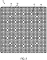
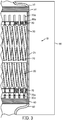
- FIGS. 1-3 illustrate a fuel assembly 10. As shown in FIG. 3 , the fuel assembly 10 comprises a plurality of fuel elements 20 supported by a frame 25.
- the frame 25 comprises a shroud 30, guide tubes 40, an upper nozzle 50, a lower nozzle 60, a lower tie plate 70, an upper tie plate 80, and/or other structure(s) that enable the assembly 10 to operate as a fuel assembly in a nuclear reactor.
- One or more of these components of the frame 25 may be omitted without deviating from the scope of the disclosure.
- the shroud 25 mounts to the upper nozzle 50 and lower nozzle 60.
- the lower nozzle 60 (or other suitable structure of the assembly 10) is constructed and shaped to provide a fluid communication interface between the assembly 10 and the reactor 90 into which the assembly 10 is placed so as to facilitate coolant flow into the reactor core through the assembly 10 via the lower nozzle 60.
- the upper nozzle 50 facilitates direction of the heated coolant from the assembly 10 to the power plant's steam generators (for PWRs), turbines (for BWRs), etc.
- the nozzles 50, 60 have a shape that is specifically designed to properly mate with the reactor core internal structure.
- the lower tie plate 70 and upper tie plate 80 are preferably rigidly mounted (e.g., via welding, suitable fasteners (e.g., bolts, screws), etc.) to the shroud 30 or lower nozzle 60 (and/or other suitable structural components of the assembly 10).
- suitable fasteners e.g., bolts, screws
- Lower axial ends of the elements 20 form pins 20a that fit into holes 70a in the lower tie plate 70 to support the elements 20 and help maintain proper element 20 spacing.
- the pins 20a mount to the holes 70a in a manner that prevents the elements 20 from rotating about their axes or axially moving relative to the lower tie plate 70. This restriction on rotation helps to ensure that contact points between adjacent elements 20 all occur at the same axial positions along the elements 20 (e.g., at self-spacing planes discussed below).
- connection between the pins 20a and holes 70a may be created via welding, interference fit, mating non-cylindrical features that prevent rotation (e.g., keyway and spline), and/or any other suitable mechanism for restricting axial and/or rotational movement of the elements 20 relative to the lower tie plate 70.
- the lower tie plate 70 includes axially extending channels (e.g., a grid of openings) through which coolant flows toward the elements 20.
- Upper axial ends of the elements 20 form pins 20a that freely fit into holes 80a in the upper tie plate 80 to permit the upper pins 20a to freely axially move upwardly through to the upper tie plate 80 while helping to maintain the spacing between elements 20.
- the elongating elements 20 can freely extend further into the upper tie plate 80.
- the pins 70a transition into a central portion of the element 20.
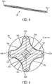
- FIGS. 4 and 5 illustrate an individual fuel element/rod 20 of the assembly 10. As shown in FIG. 5 , the elongated central portion of the fuel element 20 has a four-lobed cross-section. A cross-section of the element 20 remains substantially uniform over the length of the central portion of the element 20.
- Each fuel element 20 has a fuel kernel 100, which includes a refractory metal and fuel material that includes fissile material.
- a displacer 110 that comprises a refractory metal is placed along the longitudinal axis in the center of the fuel kernel 100.
- the displacer 110 helps to limit the temperature in the center of the thickest part of the fuel element 20 by displacing fissile material that would otherwise occupy such space and minimize variations in heat flux along the surface of the fuel element.
- the displacer 110 may be eliminated altogether.
- the fuel kernel 100 is enclosed by a refractory metal cladding 120.
- the cladding 120 is preferably thick enough, strong enough, and flexible enough to endure the radiation-induced swelling of the kernel 100 without failure (e.g., without exposing the kernel 100 to the environment outside the cladding 120).
- the entire cladding 120 is at least 0.3 mm, 0.4 mm, 0.5 mm, and/or 0.7 mm thick.
- the cladding 120 thickness is at least 0.4 mm in order to reduce a chance of swelling-based failure, oxidation based failure, and/or any other failure mechanism of the cladding 120.
- the cladding 120 may have a substantially uniform thickness in the annular direction (i.e., around the perimeter of the cladding 120 as shown in the cross-sectional view of FIG. 5 ) and over the axial/longitudinal length of the kernel 100 (as shown in FIG. 4 ).
- the cladding 120 is thicker at the tips of the lobes 20b than at the concave intersection/area 20c between the lobes 20b.
- the cladding 120 at the tips of the lobes 20b is at least 10%, 20%, 30%, 40%, 50%, 60%, 70%, 80%, 90%, 100%, 125%, and/or 150% thicker than the cladding 120 at the concave intersections/areas 20c.
- the thicker cladding 120 at the tips of the lobes 20b provides improved wear resistance at the tips of the lobes 20b where adjacent fuel elements 20 touch each other at the self-spacing planes (discussed below).
- the refractory metal used in the displacer 110, the fuel kernel 100, and the cladding 120 comprises zirconium.
- zirconium means pure zirconium or zirconium in combination with other alloy material(s).
- other refractory metals may be used instead of zirconium (e.g., niobium, molybdenum, tantalum, tungsten, rhenium, titanium, vanadium, chromium, zirconium, hafnium, ruthenium, osmium, iridium, and/or other metals).
- the term "refractory metal” means any metal/alloy that has a melting point above 1800 degrees Celsius (2073K).
- the refractory metal may be replaced with another non-fuel metal, e.g., aluminum.
- a non-refractory non-fuel metal is best suited for reactor cores that operate at lower temperatures (e.g., small cores that have a height of about 1 meter and an electric power rating of 100 MWe or less). Refractory metals are preferred for use in cores with higher operating temperatures.
- the central portion of the fuel kernel 100 and cladding 120 has a four-lobed profile forming spiral spacer ribs 130.
- the displacer 110 may also be shaped so as to protrude outwardly at the ribs 130 (e.g., corners of the square displacer 110 are aligned with the ribs 130).
- the fuel elements 20 may have greater or fewer numbers of ribs 130 without deviating from the scope of the present invention.
- a fuel element may have three ribs/lobes, which are preferably equally circumferentially spaced from each other.
- the number of lobes/ribs 130 may depend, at least in part, on the shape of the fuel assembly 10.
- a four-lobed element 20 may work well with a square cross-sectioned fuel assembly 10 (e.g., as is used in the AP-1000).
- a three-lobed fuel element may work well with a hexagonal fuel assembly (e.g., as is used in the VVER).
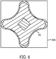
- FIG. 9 illustrates various dimensions of the fuel element 20. Any of these dimensions, parameters and/or ranges, as identified in the below table, can be increased or decreased by up to 5%, 10%, 15%, 20%, 25%, 30%, 40%, 50%, or more.
- the displacer 110 has a cross-sectional shape of a square regular quadrilateral with the corners of the square regular quadrilateral being aligned with the ribs 130.
- the displacer 110 forms a spiral that follows the spiral of the ribs 130 so that the corners of the displacer 110 remain aligned with the ribs 130 along the axial length of the fuel kernel 100.
- the displacer 110 preferably has the cross-sectional shape of a regular polygon having as many sides as the element 20 has ribs.
- the cross-sectional area of the central portion of the element 20 is preferably substantially smaller than the area of a square 200 in which the tip of each of the ribs 130 is tangent to one side of the square 200.
- the cross-sectional area of an element 20 having n ribs is preferably smaller than the area of a regular polygon having n sides in which the tip of each of the ribs 130 is tangent to one side of the polygon.
- a ratio of the area of the element 20 to the area of the square (or relevant regular polygon for elements 20 having greater or fewer than four ribs 130) is less than 0.7, 0.6, 0.5, 0.4, 0.35, 0.3.
- this area ratio approximates how much of the available space within the shroud 30 is taken up by the fuel elements 20, such that a lower ratio means that more space is advantageously available for coolant, which also acts as a neutron moderator and which increases the moderator-to-fuel ratio (important for neutronics), reduces hydraulic drag, and increases the heat transfer from the elements 20 to the coolant.
- the resulting moderator to fuel ratio is at least 2.0, 2.25, 2.5, 2.75, and/or 3.0 (as opposed to 1.96 when conventional cylindrical uranium oxide rods are used).
- the fuel assembly 10 flow area is increased by over 16% as compared to the use of one or more conventional fuel assemblies that use cylindrical uranium oxide rods. The increased flow area may decrease the coolant pressure drop through the assembly 10 (relative to conventional uranium oxide assemblies), which may have advantages with respect to pumping coolant through the assembly 10.
- the element 20 is axially elongated.
- each element 20 is a full-length element and extends the entire way from lower tie plate 70 at or near the bottom of the assembly 10 to the upper tie plate 80 at or near the top of the assembly 10. This may result in elements 20 that are anywhere from 1 meter long (for compact reactors) to over 4 meters long. Thus, for typical reactors, the elements 20 may be between 1 and 5 meters long. However, the elements 20 may be lengthened or shortened to accommodate any other sized reactor without deviating from the scope of the present invention.
- the elements 20 may alternatively be segmented, such that the multiple segments together make a full length element.
- 4 individual 1 meter element segments 20 may be aligned end to end to effectively create the full-length element.
- Additional tie plates 70, 80 may be provided at the intersections between segments to maintain the axial spacing and arrangement of the segments.
- the fuel kernel 100 comprises a combination of a refractory metal/alloy and fuel material.
- the refractory metal/alloy may comprise a zirconium alloy.
- the fuel material may comprise low enriched uranium (e.g., U235, U233), plutonium, or thorium combined with low enriched uranium as defined below and/or plutonium.
- low enriched uranium means that the whole fuel material contains less than 20% by weight fissile material (e.g., uranium-235 or uranium-233).
- the uranium fuel material is enriched to between 1% and 20%, 5% and 20%, 10% and 20%, and/or 15% and 20% by weight of uranium-235.
- the fuel material comprises 19.7% enriched uranium-235.
- the fuel material may comprise a 3-10%, 10-40%, 15-35%, and/or 20-30% volume fraction of the fuel kernel 100.
- the refractory metal may comprise a 60-99%, 60-97%, 70-97%, 60-90%, 65-85%, and/or 70-80% volume fraction of the fuel kernel 100. Volume fractions within one or more of these ranges provide an alloy with beneficial properties as defined by the material phase diagram for the specified alloy composition.
- the fuel kernel 100 comprises a Zr-U alloy that is a high-alloy fuel (i.e., relatively high concentration of the alloy constituent relative to the uranium constituent) comprised of either ⁇ -phase UZr 2 , or a combination of ⁇ -phase UZr 2 and ⁇ -phase Zr.
- the ⁇ -phase of the U-Zr binary alloy system may range from a zirconium composition of approximately 65-81 volume percent (approximately 63 to 80 atom percent) of the fuel kernel 100. These examples have been found to result in low volumetric, irradiation-induced swelling of the fuel element 20. Fission gases are entrained within the metal kernel 100 itself, such that the fuel element 20 can omit a conventional gas gap from the fuel element 20.
- Such swelling may be significantly less than would occur if low alloy ( ⁇ -phase only) compositions were used (e.g., at least 10%, 20%, 30%, 50%, 75%, 100%, 200%, 300%, 500%, 1000%, 1200%, 1500%, or greater reduction in volume percent swelling per atom percent burnup than if a low alloy ⁇ -phase U-10Zr fuel was used).
- Irradiation-induced swelling of the fuel element 20 or kernel 100 thereof may be less than 20, 15, 10, 5, 4, 3, and/or 2 volume percent per atom percent burnup. Swelling is expected to be around one volume percent per atom percent burnup.
- the fuel kernel may be replaced with a plutonium-zirconium binary alloy with the same or similar volume percentages as with the above-discussed U-Zr fuel kernels 100, or with different volume percentages than with the above-discussed U-Zr fuel kernels 100.
- the plutonium fraction in the kernel 100 may be substantially less than a corresponding uranium fraction in a corresponding uranium-based kernel 100 because plutonium typically has about 60-70% weight fraction of fissile isotopes, while LEU uranium has 20% or less weight fraction of fissile U-235 isotopes.
- the plutonium volume fraction in the kernel 100 may be less than 15%, less than 10%, and/or less than 5%, with the volume fraction of the refractory metal being adjusted accordingly.
- the use of a high-alloy kernel 100 may also result in the advantageous retention of fission gases during irradiation.
- Oxide fuels and low-alloy metal fuels typically exhibit significant fission gas release that is typically accommodated by the fuel design, usually with a plenum within the fuel rod to contain released fission gases.
- the fuel kernel 100 according to one or more examples of the present disclosure, in contrast, does not release fission gases. This is in part due to the low operating temperature of the fuel kernel 100 and the fact that fission gas atoms (specifically Xe and Kr) behave like solid fission products. Fission gas bubble formation and migration along grain boundaries to the exterior of the fuel kernel 100 does not occur.
- fission gas bubbles may form. However, these bubbles remain isolated within the fuel kernel 100 and do not form an interconnected network that would facilitate fission gas release.
- the metallurgical bond between the fuel kernel 100 and cladding 120 may provide an additional barrier to fission gas release.
- the fuel kernel 100 (or the cladding 120 or other suitable part of the fuel element 20) of one or more of the fuel elements 20 can be alloyed with a burnable poison such as gadolinium, boron, erbium or other suitable neutron absorbing material to form an integral burnable poison fuel element.
- a burnable poison such as gadolinium, boron, erbium or other suitable neutron absorbing material to form an integral burnable poison fuel element.
- Different fuel elements 20 within a fuel assembly 10 may utilize different burnable poisons and/or different amounts of burnable poison.
- some of fuel elements 20 of a fuel assembly 10 may include kernels 100 with 25, 20, and/or 15 weight percent or less Gd (e.g., 1-25 weight percent, 1-15 weight percent, 5-15 weight percent, etc.).
- Other fuel elements 20 of the fuel assembly 10 may include kernels 100 with 10 or 5 weight percent or less Er (e.g., 0.1-10.0 weight percent, 0.1 to 5.0 weight percent etc.).
- the burnable poison displaces the fuel material (rather than the refractory metal) relative to fuel elements 20 that do not include burnable poison in their kernels 100.
- the fuel element 20 includes a kernel 100 that is 16.5 volume percent Gd, 65 volume percent zirconium, and 18.5 volume percent uranium.
- the burnable poison instead displaces the refractory metal, rather than the fuel material.
- the burnable poison in the fuel kernel 100 displaces the refractory metal and the fuel material proportionally.
- the burnable poison within the fuel kernel 100 may be disposed in the ⁇ -phase of UZr 2 or ⁇ -phase of Zr such that the presence of the burnable poison does not change the phase of the UZr 2 alloy or Zr alloy in which the burnable poison is disposed.
- Fuel elements 20 with a kernel 100 with a burnable poison may make up a portion (e.g., 0-100%, 1-99%, 1-50%, etc.) of the fuel elements 20 of one or more fuel assemblies 10 used in a reactor core.
- fuel elements 20 with burnable poison may be positioned in strategic locations within the fuel assembly lattice of the assembly 10 that also includes fuel elements 20 without burnable poison to provide power distribution control and to reduce soluble boron concentrations early in the operating cycle.
- select fuel assemblies 10 that include fuel elements 20 with burnable poison may be positioned in strategic locations within the reactor core relative to assemblies 10 that do not include fuel elements 20 with burnable poison to provide power distribution control and to reduce soluble boron concentrations early in the operating cycle.
- the use of such integral burnable absorbers may facilitate the design of extended operating cycles.
- non-fuel bearing burnable poison rods may be included in the fuel assembly 10 (e.g., adjacent to fuel elements 20, in place of one or more fuel elements 20, inserted into guide tubes in fuel assemblies 10 that do not receive control rods, etc.).
- non-fuel burnable poison rods can be designed into a spider assembly similar to that which is used in the Babcock and Wilcox or Westinghouse designed reactors (referred to as burnable poison rod assemblies (BPRA)). These then may be inserted into the control rod guide tubes and locked into select fuel assemblies 10 where there are no control banks for the initial cycle of operation for reactivity control. When the burnable poison cluster is used it may be removed when the fuel assembly is relocated for the next fuel cycle.
- BPRA burnable poison rod assemblies
- the non-fuel burnable poison rods remain in the fuel assembly 10 and are discharged along with other fuel elements 20 when the fuel assembly 10 reaches its usable life.
- the fuel elements 20 are manufactured via powder-metallurgy co-extrusion.
- the powdered refractory metal and powdered metal fuel material (as well as the powdered burnable poison, if included in the kernel 100) for the fuel kernel 100 are mixed, the displacer 110 blank is positioned within the powder mixture, and then the combination of powder and displacer 110 is pressed and sintered into fuel core stock/billet (e.g., in a mold that is heated to varying extents over various time periods so as to sinter the mixture).
- the displacer 110 blank may have the same or similar cross-sectional shape as the ultimately formed displacer 110.
- the displacer 110 blank may have a shape that is designed to deform into the intended cross-sectional shape of the displacer 110 upon extrusion.
- the fuel core stock (including the displacer 110 and the sintered fuel kernel 100 material) is inserted into a hollow cladding 120 tube that has a sealed tube base and an opening on the other end. The opening on the other end is then sealed by an end plug made of the same material as the cladding to form a billet.
- the billet may be cylindrically shaped, or may have a shape that more closely resembles the ultimate cross-sectional shape of the element 20, for example, as shown in FIGS. 5 and 9 .
- the billet is then co-extruded under temperature and pressure through a die set to create the element 20, including the finally shaped kernel 100, cladding 110, and displacer 120.
- the billet may be properly oriented relative to the extrusion press die so that corners of the displacer 110 align with the lobes 20b of the fuel element 20.
- the extrusion process may be done by either direct extrusion (i.e., moving the billet through a stationary die) or indirect extrusion (i.e., moving the die toward a stationary billet).
- the process results in the cladding 120 being metallurgically bonded to the fuel kernel 100, which reduces the risk of delamination of the cladding 120 from the fuel kernel 100.
- the tube and end plug of the cladding 120 metallurgically bond to each other to seal the fuel kernel 100 within the cladding 120.
- the high melting points of refractory metals used in the fuel elements 10 tend to make powder metallurgy the method of choice for fabricating components from these metals.
- the fuel core stock of the fuel elements 20 may be manufactured via casting instead of sintering.
- Powdered or monolithic refractory metal and powdered or monolithic fuel material (as well as the powdered burnable poison, if included in the kernel 100) may be mixed, melted, and cast into a mold.
- the mold may create a displacer-blank-shaped void in the cast kernel 100 such that the displacer 110 blank may be inserted after the kernel 100 is cast, in the same manner that the cladding 120 is added to form the billet to be extruded.
- the remaining steps for manufacturing the fuel elements 20 may remain the same as or similar to the above-discuss embodiment that utilizes sintering instead of casting. Subsequent extrusion results in metallurgical bonding between the displacer 110 and kernel 100, as well as between the kernel 100 and cladding 120.
- the fuel elements 20 are manufactured using powdered ceramic fuel material instead of powdered metal fuel material.
- the remaining manufacturing steps may be the same as discussed above with respect to the embodiments using powdered metal fuel material.
- the manufacturing process may result in a fuel kernel 100 comprising fuel material disposed in a matrix of metal non-fuel material.
- the resulting fuel kernel 100 comprises a metal fuel alloy kernel comprising an alloy of the metal fuel material and the matrix of metal non-fuel material (e.g., a uranium-zirconium alloy).
- the kernel 100 comprises ceramic fuel material disposed in (e.g., interspersed throughout) the matrix of metal non-fuel material.
- the ceramic fuel material used in the manufacturing process may comprise powdered uranium or plutonium oxide, powdered uranium or plutonium nitride, powdered uranium or plutonium carbide, powdered uranium or plutonium hydride, or a combination thereof.
- the manufacturing process results in ceramic fuel being disposed in a solid matrix of non-fuel material (e.g., a zirconium matrix).
- the axial coiling pitch of the spiral ribs 130 is selected according to the condition of placing the axes of adjacent fuel elements 10 with a spacing equal to the width across corners in the cross section of a fuel element and may be 5% to 20% of the fuel element 20 length.
- the pitch i.e., the axial length over which a lobe/rib makes a complete rotation
- the pitch is about 21.5 cm, while the full active length of the element 20 is about 420 cm.
- stability of the vertical arrangement of the fuel elements 10 is provided: at the bottom - by the lower tie plate 70; at the top - by the upper tie plate 80; and relative to the height of the core - by the shroud 30.
- the fuel elements 10 have a circumferential orientation such that the lobed profiles of any two adjacent fuel elements 10 have a common plane of symmetry which passes through the axes of the two adjacent fuel elements 10 in at least one cross section of the fuel element bundle.
- the helical twist of the fuel elements 20 in combination with their orientation ensures that there exists one or more self-spacing planes.
- the ribs of adjacent elements 20 contact each other to ensure proper spacing between such elements 20.
- the center-to-center spacing of elements 20 will be about the same as the comer-to-comer width of each element 20 (12.6 mm in the element illustrated in FIG. 5 ).
- all adjacent fuel elements 20 or only a portion of the adjacent fuel elements 20 will contact each other.
- each fuel element 20 contacts all four adjacent fuel elements 20 at each self-spacing plane.
- each fuel element will only contact three of the six adjacent fuel elements in a given self-spacing plane.
- the three-lobed fuel element will contact the other three adjacent fuel elements in the next axially-spaced self-spacing plane (i.e., 1/6 of a turn offset from the previous self-spacing plane).
- a self-spacing plane will exist every 1/n helical turn (e.g., every 1 ⁇ 4 helical turn for a four-lobed element 20 arranged in a square pattern such that four other fuel elements 20 are adjacent to the fuel element 20; every 1/3 helical turn for a three-lobed element in which three fuel elements are adjacent to the fuel element (i.e., every 120 degrees around the perimeter of the fuel element)).
- the pitch of the helix may be modified to create greater or fewer self-spacing planes over the axial length of the fuel elements 20.
- Each four-lobed fuel element 20 includes multiple twists such that there are multiple self-spacing planes over the axial length of the bundle of fuel elements 20.
- All of the elements 20 twist in the same direction. However, adjacent elements 20 may twist in opposite directions.
- the fuel assembly 10 may omit spacer grids that may otherwise have been necessary to assure proper element spacing along the length of the assembly 10.
- coolant may more freely flow through the assembly 10, which advantageously increases the heat transfer from the elements 20 to the coolant.
- the assembly 10 may include spacer grid(s).
- the shroud 30 forms a tubular shell that extends axially along the entire length of the fuel elements 20 and surrounds the elements 20.
- the shroud 30 may comprise axially-spaced bands, each of which surrounds the fuel elements 20.
- One or more such bands may be axially aligned with the self-spacing planes.
- Axially extending corner supports may extend between such axially spaced bands to support the bands, maintain the bands' alignment, and strengthen the assembly.
- holes may be cut into the otherwise tubular/polygonal shroud 30 in places where the shroud 30 is not needed or desired for support.
- Use of a full shroud 30 may facilitate greater control of the separate coolant flows through each individual fuel assembly 10.
- the use of bands or a shroud with holes may facilitate better coolant mixing between adjacent fuel assemblies 10, which may advantageously reduce coolant temperature gradients between adjacent fuel assemblies 10.
- the cross-sectional perimeter of the shroud 30 has a shape that accommodates the reactor in which the assembly 10 is used.
- the shroud In reactors such as the AP-1000 that utilize square fuel assemblies, the shroud has a square cross-section.
- the shroud 30 may alternatively take any suitable shape depending on the reactor in which it is used (e.g., a hexagonal shape for use in a VVER reactor (e.g., as shown in FIG. 1 of U.S. Patent Application Publication No. 2009/0252278 A1 ).
- the guide tubes 40 provide for the insertion of control absorber elements based on boron carbide (B 4 C), silver indium cadmium (Ag, In, Cd), dysprosium titanate (Dy 2 O3 ⁇ TiO 2 ) or other suitable alloys or materials used for reactivity control (not shown) and burnable absorber elements based on boron carbide, gadolinium oxide (Gd 2 O 3 ) or other suitable materials (not shown) and are placed in the upper nozzle 50 with the capability of elastic axial displacement.
- the guide tubes 40 may comprise a zirconium alloy.
- the guide tube 40 arrangement shown in FIG. 1 is in an arrangement used in the AP-1000 reactor (e.g., 24 guide tubes arranged in two annular rows at the positions shown in the 17x17 grid).
- the frame 25 may be shaped and configured to fit into a reactor core of a conventional nuclear power plant in place of a conventional uranium oxide or mixed oxide fuel assembly for that plant's reactor core.
- the nuclear power plant may comprise a reactor core design that was in actual use before 2010 (e.g., 2, 3 or 4-loop PWRs; BWR-4).
- the nuclear power plant may be of an entirely new design that is specifically tailored for use with the fuel assembly 10.
- the illustrated fuel assembly 10 is designed for use in an AP-1000 or EPR reactor.
- the assembly includes a 17x17 array of fuel elements 20, 24 of which are replaced with guide tubes 40 as explained above for a total of 265 fuel elements 20 in EPR or 264 fuel elements 20 in AP-1000 (in the AP-1000, in addition to the 24 fuel elements being replaced with the guide tubes, a central fuel element is also replaced with an instrumented tube).
- the elements 20 preferably provide 100% of the overall fissile material of the fuel assembly 10.
- some of the fissile material of the assembly 10 may be provided via fuel elements other than the elements 20 (e.g., non-lobed fuel elements, uranium oxide elements, elements having fuel ratios and/or enrichments that differ from the elements 20).
- the fuel elements 20 provide at least 50%, 60%, 70%, 75%, 80%, 85%, 90%, and/or 95% by volume of the overall fissile material of the fuel assembly 10.
- the metal fuel elements 20 facilitate various advantages over the uranium oxide or mixed oxide fuel conventionally used in light water nuclear reactors (LWR) (including boiling water reactors and pressurized water reactors) such as the Westinghouse-designed AP-1000, AREVA-designed EPR reactors, or GE-designed ABWR.
- LWR light water nuclear reactors
- the power rating for an LWR operating on standard uranium oxide or mixed oxide fuel could be increased by up to about 30% by substituting the all-metal fuel elements 20 and/or fuel assembly 10 for standard uranium oxide fuel and fuel assemblies currently used in existing types of LWRs or new types of LWRs that have been proposed.
- the lack of spacer grids may reduce hydraulic resistance, and therefore increase coolant flow and heat flux from the elements 20 to the primary coolant.
- the helical twist of the fuel elements 20 may increase coolant intermixing and turbulence, which may also increase heat flux from the elements 20 to the coolant.
- conventional power plants could be upgraded (e.g., larger and/or additional coolant pumps, steam generators, heat exchangers, pressurizers, turbines). Indeed, the upgrade could provide 30-40% more electricity from an existing reactor. Such a possibility may avoid the need to build a complete second reactor. The modification cost may quickly pay for itself via increased electrical output. Alternatively, new power plants could be constructed to include adequate features to handle and utilize the higher thermal output of the assemblies 10.
- one or more examples of the disclosure could allow an LWR to operate at the same power rating as with standard uranium oxide or mixed oxide fuel using existing reactor systems without any major reactor modifications. For example:
- fuel assemblies 10 according to the present disclosure can be phased/laddered into a reactor core in place of conventional fuel assemblies.
- fuel assemblies 10 having comparable fissile/neutronic/thermal outputs as conventional fuel assemblies can gradually replace such conventional fuel assemblies over sequential fuel changes without changing the operating parameters of the power plant.
- fuel assemblies 10 can be retrofitted into an existing core that may be important during a transition period (i.e., start with a partial core with fuel assemblies 10 and gradually transition to a full core of fuel assemblies 10).
- the fissile loading of assemblies 10 can be tailored to the particular transition desired by a plant operator.
- the fissile loading can be increased appropriately so as to increase the thermal output of the reactor by anywhere from 0% to 30% or more higher, relative to the use of conventional fuel assemblies that the assemblies 10 replace. Consequently, the power plant operator can chose the specific power uprate desired, based on the existing plant infrastructure or the capabilities of the power plant at various times during upgrades.
- the non-fuel metal of the fuel kernel 100 is preferably a refractory metal, for example a molybdenum alloy (e.g., pure molybdenum or a combination of molybdenum and other metals), and the cladding 120 is preferably stainless steel (which includes any alloy variation thereof) or other material suitable for use with coolant in such reactors (e.g., sodium).
- a molybdenum alloy e.g., pure molybdenum or a combination of molybdenum and other metals
- the cladding 120 is preferably stainless steel (which includes any alloy variation thereof) or other material suitable for use with coolant in such reactors (e.g., sodium).
- Such fuel elements 20 may be manufactured via the above-discussed co-extrusion process or may be manufactured by any other suitable method (e.g., vacuum melt).
- fuel assemblies 510 may be used in a pressurized heavy water reactor 500 (see FIG. 8 ) such as a CANDU reactor.
- the fuel assembly 510 comprises a plurality of fuel elements 20 mounted to a frame 520.
- the frame 520 comprises two end plates 520a, 520b that mount to opposite axial ends of the fuel elements 20 (e.g., via welding, interference fits, any of the various types of attachment methods described above for attaching the elements 20 to the lower tie plate70).
- the elements 20 used in the fuel assembly 510 are typically much shorter than the elements 20 used in the assembly 10. According to various embodiments and reactors 500, the elements 20 and assemblies 510 used in the reactor 500 may be about 18 inches long.
- the elements 20 may be positioned relative to each other in the assembly 510 so that self-spacing planes maintain spacing between the elements 20 in the manner described above with respect to the assembly 10.
- the elements 20 of the assembly 510 may be so spaced from each other that adjacent elements 20 never touch each other, and instead rely entirely on the frame 520 to maintain element 20 spacing.
- spacers may be attached to the elements 20 or their ribs at various positions along the axial length of the elements 20 to contact adjacent elements 20 and help maintain element spacing 20 (e.g., in a manner similar to how spacers are used on conventional fuel rods of conventional fuel assemblies for pressurized heavy water reactors to help maintain rod spacing).
- the assemblies 510 are fed into calandria tubes 500a of the reactor 500 (sometimes referred to in the art as a calandria 500).
- the reactor 500 uses heavy water 500b as a moderator and primary coolant.
- the primary coolant 500b circulates horizontally through the tubes 500a and then to a heat exchanger where heat is transferred to a secondary coolant loop that is typically used to generate electricity via turbines.
- Fuel assembly loading mechanisms (not shown) are used to load fuel assemblies 510 into one side of the calandria tubes 500a and push spent assemblies 510 out of the opposite side of the tubes 500a, typically while the reactor 500 is operating.
- the fuel assemblies 510 may be designed to be a direct substitute for conventional fuel assemblies (also known as fuel bundles in the art) for existing, conventional pressurized heavy water reactors (e.g., CANDU reactors). In such an example, the assemblies 510 are fed into the reactor 500 in place of the conventional assemblies/bundles. Such fuel assemblies 510 may be designed to have neutronic/thermal properties similar to the conventional assemblies being replaced. Alternatively, the fuel assemblies 510 may be designed to provide a thermal power uprate. In such uprate examples, new or upgraded reactors 500 can be designed to accommodate the higher thermal output.
- the fuel assembly 10 is designed to replace a conventional fuel assembly of a conventional nuclear reactor.
- the fuel assembly 10 illustrated in FIG. 1 is specifically designed to replace a conventional fuel assembly that utilizes a 17x17 array of UO 2 fuel rods. If the guide tubes 40 of the assembly 10 are left in the exact same position as they would be for use with a conventional fuel assembly, and if all of the fuel elements 20 are the same size, then the pitch between fuel elements/rods remains unchanged between the conventional UO 2 fuel assembly and one or more examples of the fuel assembly 10 (e.g., 12.6 mm pitch). In other words, the longitudinal axes of the fuel elements 20 may be disposed in the same locations as the longitudinal axes of conventional UO 2 fuel rods would be in a comparable conventional fuel assembly.
- the fuel elements 20 may have a larger circumscribed diameter than the comparable UO 2 fuel rods (e.g., 12.6 mm as compared to an outer diameter of 9.5 mm for a typical UO 2 fuel rod).
- a larger circumscribed diameter e.g. 12.6 mm as compared to an outer diameter of 9.5 mm for a typical UO 2 fuel rod.
- the cross-sectional length and width of the space occupied by the fuel elements 20 may be slightly larger than that occupied by conventional UO 2 fuel rods in a conventional fuel assembly (e.g., 214.2 mm for the fuel assembly 10 (i.e., 17 fuel elements 20 x 12.6 mm circumscribed diameter per fuel element), as opposed to 211.1 mm for a conventional UO 2 fuel assembly that includes a 17 x 17 array of 9.5 mm UO 2 fuel rods separated from each other by a 12.6 mm pitch).
- a spacer grid surrounds the fuel rods, and increases the overall cross-sectional envelope of the conventional fuel assembly to 214 mm x 214 mm.
- the shroud 30 similarly increases the cross-sectional envelope of the fuel assembly 10.
- the shroud 30 may be any suitable thickness (e.g., 0.5 mm or 1.0 mm thick).
- the overall cross-sectional envelope of an embodiment of the fuel assembly 10 may be 216.2 mm x 216.2 mm (e.g., the 214 mm occupied by the 17 12.6 mm diameter fuel elements 20 plus twice the 1.0 mm thickness of the shroud 30).
- the fuel assembly 10 may be slightly larger (e.g., 216.2 mm x 216.2 mm) than a typical UO 2 fuel assembly (214 mm x 214 mm).
- the larger size may impair the ability of the assembly 10 to properly fit into the fuel assembly positions of one or more conventional reactors, which were designed for use with conventional UO 2 fuel assemblies.
- a new reactor may be designed and built to accommodate the larger size of the fuel assemblies 10.
- the circumscribed diameter of all of the fuel elements 20 may be reduced slightly so as to reduce the overall cross-sectional size of the fuel assembly 10.
- the circumscribed diameter of each fuel element 20 may be reduced by 0.13 mm to 12.47 mm, so that the overall cross-sectional space occupied by the fuel assembly 10 remains comparable to a conventional 214 mm by 214 mm fuel assembly (e.g., 17 12.47 mm diameter fuel elements 20 plus two 1.0 mm thickness of the shroud, which totals about 214 mm).
- a reduction in the size of the 17 by 17 array will slightly change the positions of the guide tubes 40 in the fuel assembly 10 relative to the guide tube positions in a conventional fuel assembly.
- the positions of the corresponding control rod array and control rod drive mechanisms in the reactor may be similarly shifted to accommodate the repositioned guide tubes 40.
- conventionally positioned control rods may adequately fit into the slightly shifted tubes 40 of the fuel assembly 10.
- the diameter of the peripheral fuel elements 20 may be reduced slightly so that the overall assembly 10 fits into a conventional reactor designed for conventional fuel assemblies.
- the circumscribed diameter of the outer row of fuel elements 20 may be reduced by 1.1 mm such that the total size of the fuel assembly is 214 mm x 214 mm (e.g., 15 12.6 mm fuel elements 20 plus 2 11.5 mm fuel elements 20 plus 2 1.0 mm thicknesses of the shroud 30).
- the circumscribed diameter of the outer two rows of fuel elements 20 may be reduced by 0.55 mm each such that the total size of the fuel assembly remains 214 mm x 214 mm (e.g., 13 12.6 mm fuel elements 20 plus 4 12.05 mm fuel assemblies plus 2 1.0 mm thicknesses of the shroud 30).
- the pitch and position of the central 13x13 array of fuel elements 20 and guide tubes 40 remains unaltered such that the guide tubes 40 align with the control rod array and control rod drive mechanisms in a conventional reactor.
- FIG. 10 illustrates a fuel assembly 610 according to an alternative example.
- the fuel assembly 610 is designed to replace a conventional UO 2 fuel assembly in a conventional reactor while maintaining the control rod positioning of reactors designed for use with various conventional UO 2 fuel assemblies.
- the fuel assembly 610 is generally similar to the fuel assembly 10, which is described above and illustrated in FIG. 1 , but includes several differences that help the assembly 610 to better fit into one or more existing reactor types (e.g., reactors using Westinghouse's fuel assembly design that utilizes a 17 by 17 array of UO 2 rods) without modifying the control rod positions or control rod drive mechanisms.
- the fuel assembly includes a 17 by 17 array of spaces.
- the central 15 by 15 array is occupied by 200 fuel elements 20 and 25 guide tubes 40, as described above with respect to the similar fuel assembly 10 illustrated in FIG. 1 .
- the central guide tube 40 may be replaced by an additional fuel element 20 if the reactor design does not utilize a central tube 40 (i.e., 201 fuel elements 20 and 24 guide tubes 40).
- the guide tube 40 positions correspond to the guide tube positions used in reactors designed to use conventional UO 2 fuel assemblies.
- the peripheral positions (i.e., the positions disposed laterally outward from the fuel elements 20) of the 17 by 17 array/pattern of the fuel assembly 610 are occupied by 64 UO 2 fuel elements/rods 650.
- the fuel rods 650 may comprise standard UO 2 pelletized fuel disposed in a hollow rod.
- the UO 2 pelletized fuel may be enriched with U-235 by less than 20%, less than 15%, less than 10%, and/or less than 5%.
- the rods 650 may have a slightly smaller diameter (e.g., 9.50 mm) than the circumscribed diameter of the fuel elements 20, which slightly reduces the overall cross-sectional dimensions of the fuel assembly 610 so that the assembly 610 better fits into the space allocated for a conventional UO 2 fuel assembly.
- the fuel rods/elements 650 comprise UO 2 pelletized fuel.
- the fuel rods/elements 650 may alternatively utilize any other suitable combination of one or more fissile and/or fertile materials (e.g., thorium, plutonium, uranium-235, uranium-233, any combinations thereof).
- Such fuel rods/elements 650 may comprise metal and/or oxide fuel.
- the fuel rods 650 may occupy less than all of the 64 peripheral positions.
- the fuel rods 650 may occupy the top row and left column of the periphery, while the bottom row and right column of the periphery may be occupied by fuel elements 20.
- the fuel rods 650 may occupy any other two sides of the periphery of the fuel assembly.
- the shroud 630 may be modified so as to enclose the additional fuel elements 20 in the periphery of the fuel assembly.
- Such modified fuel assemblies may be positioned adjacent each other such that a row/column of peripheral fuel elements 650 in one assembly is always adjacent to a row/column of fuel elements 20 in the adjacent fuel assembly.
- a shroud 630 surrounds the array of fuel elements 20 and separates the elements 20 from the elements 650.
- the nozzles 50, 60, shroud 630, coolant passages formed therebetween, relative pressure drops through the elements 20 and elements 650, and/or the increased pressure drop through the spacer grid 660 (discussed below) surrounding the elements 650 may result in a higher coolant flow rate within the shroud 630 and past the higher heat output fuel elements 20 than the flow rate outside of the shroud 630 and past the relatively lower heat output fuel rods 650.
- the passageways and/or orifices therein may be designed to optimize the relative coolant flow rates past the elements 20, 650 based on their respective heat outputs and designed operating temperatures.
- the moderator:fuel ratio for the fuel elements 20 of the fuel assembly 610 is less than or equal to 2.4.
- the moderator:fuel ratio equals a ratio of
- the shroud 630 may be replaced with one or more annular bands or may be provided with holes in the shroud 630, as explained above.
- the use of bands or holes in the shroud 630 may facilitate cross-mixing of coolant between the fuel elements 20 and the fuel elements 650.
- the fuel elements 650 are disposed within an annular spacer grid 660 that is generally comparable to the outer part of a spacer grid used in a conventional UO 2 fuel assembly.
- the spacer grid 660 may rigidly connect to the shroud 630 (e.g., via welds, bolts, screws, or other fasteners).
- the spacer grid 660 is preferably sized so as to provide the same pitch between the fuel elements 650 and the fuel elements 20 as is provided between the central fuel elements 20 (e.g., 12.6 mm pitch between axes of all fuel elements 20, 650).
- the fuel elements 650 may be disposed closer to the outer side of the spacer grid 660 than to the shroud 630 and inner side of the spacer grid 660.
- the fuel assembly 610 and spacer grid 660 are also preferably sized and positioned such that the same pitch is provided between fuel elements 650 of adjacent fuel assemblies (e.g., 12.6 mm pitch).
- the spacing between any of the fuel elements 20, 650 may vary relative to the spacing between other fuel elements 20, 650 without deviating from the scope of the present invention.
- the fuel elements 20 provide at least 60%, 65%, 70%, 75%, and/or 80% of a total volume of all fissile-material-containing fuel elements 20, 650 of the fuel assembly 610.
- the fuel assembly 610 includes 201 fuel elements 20, each having a cross-sectional area of about 70 mm 2 , and 64 fuel elements 650, each having a 9.5 mm diameter
- the height of the fuel assembly 610 matches a height of a comparable conventional fuel assembly that the assembly 610 can replace (e.g., the height of a standard fuel assembly for a Westinghouse or AREVA reactor design).
- the illustrated fuel assembly 610 may be used in a 17x17 PWR such as the Westinghouse 4-loop design, AP1000, or AREVA EPR. However, the design of the fuel assembly 610 may also be modified to accommodate a variety of other reactor designs (e.g., reactor designs that utilize a hexagonal fuel assembly, in which case the outer periphery of the hexagon is occupied by UO 2 rods, while the inner positions are occupied by fuel elements 20, or boiling water reactors, or small modular reactors). While particular dimensions are described with regard to particular embodiments, a variety of alternatively dimensioned fuel elements 20, 650 and fuel assemblies 10 may be used in connection with a variety of reactors or reactor types.
- a variety of alternatively dimensioned fuel elements 20, 650 and fuel assemblies 10 may be used in connection with a variety of reactors or reactor types.
- additional rod positions of a fuel assembly may be replaced with UO 2 rods.
- the fuel assembly 610 includes UO 2 rods only in the outer peripheral row, the assembly 610 could alternatively include UO 2 rods in the outer two rows.
- the portion of the fuel assembly 610 that supports the fuel elements 650 is inseparable from the portion of the fuel assembly 610 that supports the fuel elements 20.
- the fuel elements 20 are not separable as a unit from the fuel elements 650 of the fuel assembly 610 (even though individual fuel elements 20, 650 may be removed from the assembly 610, for example, based on individual fuel element failure).
- the fuel elements 20 and fuel elements 650 of the fuel assembly 610 have the same designed life cycle, such that the entire fuel assembly 610 is used within the reactor, and then removed as a single spent unit.
- the increased heat output of the fuel elements 20 within the fuel assembly 610 can provide a power uprate relative to the conventional all UO 2 fuel rod assembly that the assembly 610 replaces.
- the power uprate is at least 5%, 10%, and/or 15%.
- the uprate may be between 1 and 30%, 5 and 25%, and/or 10 and 20%.
- the fuel assembly 610 provides at least an 18-month fuel cycle, but may also facilitate moving to a 24+ or 36+ month fuel cycle.
- the fuel assembly 610 which uses fuel elements 20 having the example parameters discussed above with respect to the element 20 shown in FIG. 10 , the assembly 17 provides a 17% uprate relative to a conventional UO 2 fuel assembly under the operating parameters identified in the below tables.
- Fuel Assembly Parameter Value Unit Fuel assembly design 17x17 Fuel assembly pitch 215 mm Fuel assembly envelope 214 mm Active fuel height 4200 mm Number of fuel rods 265 Fuel element 20 pitch (i.e., axis to axis spacing) 12.6 mm Average outer fuel element 20 diameter (circumscribed diameter) 12.6 mm Average minimum fuel element 20 diameter 10.44 mm Moderator to fuel ratio, seed region (around elements 20) 2.36 Moderator to fuel ratio, blanket (around the fuel rods 650) 1.9 * rv reference value
- the fuel assemblies 10, 510, 610 are preferably thermodynamically designed for and physically shaped for use in a land-based nuclear power reactor 90, 500 (e.g., land-based LWRS (including BWRs and PWRs), land-based fast reactors, land-based heavy water reactors) that is designed to generate electricity and/or heat that is used for a purpose other than electricity (e.g., desalinization, chemical processing, steam generation, etc.).
- land-based nuclear power reactors 90 include, among others, VVER, AP-1000, EPR, APR-1400, ABWR, BWR-6, CANDU, BN-600, BN-800, Toshiba 4S, Monju, etc.
- the fuel assemblies 10, 510, 610 may be designed for use in and used in marine-based nuclear reactors (e.g., ship or submarine power plants; floating power plants designed to generate power (e.g., electricity) for onshore use) or other nuclear reactor applications.
- marine-based nuclear reactors e.g., ship or submarine power plants; floating power plants designed to generate power (e.g., electricity) for onshore use
- power e.g., electricity
Landscapes
- Engineering & Computer Science (AREA)
- Physics & Mathematics (AREA)
- Plasma & Fusion (AREA)
- General Engineering & Computer Science (AREA)
- High Energy & Nuclear Physics (AREA)
- Chemical & Material Sciences (AREA)
- Dispersion Chemistry (AREA)
- Ceramic Engineering (AREA)
- Manufacturing & Machinery (AREA)
- Monitoring And Testing Of Nuclear Reactors (AREA)
- Powder Metallurgy (AREA)
Applications Claiming Priority (4)
| Application Number | Priority Date | Filing Date | Title |
|---|---|---|---|
| US33346710P | 2010-05-11 | 2010-05-11 | |
| US39349910P | 2010-10-15 | 2010-10-15 | |
| US201161444990P | 2011-02-21 | 2011-02-21 | |
| EP11735927.3A EP2569776B1 (en) | 2010-05-11 | 2011-05-11 | Fuel assembly |
Related Parent Applications (2)
| Application Number | Title | Priority Date | Filing Date |
|---|---|---|---|
| EP11735927.3A Division EP2569776B1 (en) | 2010-05-11 | 2011-05-11 | Fuel assembly |
| EP11735927.3A Division-Into EP2569776B1 (en) | 2010-05-11 | 2011-05-11 | Fuel assembly |
Publications (2)
| Publication Number | Publication Date |
|---|---|
| EP3038112A1 EP3038112A1 (en) | 2016-06-29 |
| EP3038112B1 true EP3038112B1 (en) | 2017-10-25 |
Family
ID=44513305
Family Applications (2)
| Application Number | Title | Priority Date | Filing Date |
|---|---|---|---|
| EP16154148.7A Active EP3038112B1 (en) | 2010-05-11 | 2011-05-11 | Fuel assembly |
| EP11735927.3A Active EP2569776B1 (en) | 2010-05-11 | 2011-05-11 | Fuel assembly |
Family Applications After (1)
| Application Number | Title | Priority Date | Filing Date |
|---|---|---|---|
| EP11735927.3A Active EP2569776B1 (en) | 2010-05-11 | 2011-05-11 | Fuel assembly |
Country Status (11)
| Country | Link |
|---|---|
| US (5) | US10037823B2 (ja) |
| EP (2) | EP3038112B1 (ja) |
| JP (3) | JP6001530B2 (ja) |
| KR (3) | KR102165560B1 (ja) |
| CN (2) | CN105895178B (ja) |
| AU (1) | AU2011250906B2 (ja) |
| CA (2) | CA2985909C (ja) |
| EA (1) | EA023017B1 (ja) |
| ES (1) | ES2647155T3 (ja) |
| HU (2) | HUE035511T2 (ja) |
| WO (2) | WO2011143172A1 (ja) |
Families Citing this family (31)
| Publication number | Priority date | Publication date | Assignee | Title |
|---|---|---|---|---|
| CN102301430B (zh) | 2008-12-25 | 2016-06-29 | 钍能源股份有限公司 | 轻水反应堆燃料组件(替换物)、轻水反应堆和燃料组件的燃料元件 |
| US10192644B2 (en) | 2010-05-11 | 2019-01-29 | Lightbridge Corporation | Fuel assembly |
| US10170207B2 (en) * | 2013-05-10 | 2019-01-01 | Thorium Power, Inc. | Fuel assembly |
| WO2011143172A1 (en) | 2010-05-11 | 2011-11-17 | Thorium Power, Inc. | Fuel assembly with metal fuel alloy kernel and method of manufacturing thereof |
| EP2864987B1 (en) * | 2012-06-13 | 2017-09-27 | Atomic Energy of Canada Limited/ Énergie Atomique du Canada Limitée | Fuel channel assembly and fuel bundle for a nuclear reactor |
| CN103106929B (zh) * | 2013-02-04 | 2016-03-02 | 中国核动力研究设计院 | 超临界水堆的改进型环形燃料元件及其构成的燃料组件 |
| GB201318470D0 (en) * | 2013-02-25 | 2013-12-04 | Scott Ian R | A practical molten salt fission reactor |
| RU2551432C1 (ru) * | 2013-11-19 | 2015-05-27 | Открытое Акционерное Общество "Акмэ-Инжиниринг" | Оболочка для тепловыделяющего элемента, тепловыделяющий элемент и тепловыделяющая сборка |
| WO2016044439A1 (en) * | 2014-09-16 | 2016-03-24 | Lightbridge Corporation | Nuclear fuel assembly |
| JP2016156729A (ja) * | 2015-02-25 | 2016-09-01 | 株式会社 シー・アール・ワイ | 原子炉 |
| CN104681105B (zh) * | 2015-03-04 | 2017-03-01 | 东南大学 | 一种双头螺旋菱形支撑板正六边形核燃料组件 |
| JP6878251B2 (ja) * | 2017-02-09 | 2021-05-26 | 株式会社東芝 | 軽水炉用燃料集合体、軽水炉炉心設計方法および軽水炉用燃料集合体設計方法 |
| RO133588B1 (ro) * | 2017-06-23 | 2024-03-29 | Candu Energy Inc. | Aparat şi metodă pentru localizarea unui tub calandria |
| EP3655973A1 (en) * | 2017-07-19 | 2020-05-27 | TerraPower LLC | Fuel-cladding chemical interaction resistant nuclear fuel elements and methods for manufacturing the same |
| CN108213418A (zh) * | 2017-12-21 | 2018-06-29 | 中核北方核燃料元件有限公司 | 一种铀铝合金靶件芯坯制备方法 |
| JP2021507234A (ja) * | 2017-12-22 | 2021-02-22 | テラパワー, エルエルシー | 環状金属核燃料およびその製造方法 |
| EP3503119B1 (en) * | 2017-12-22 | 2023-06-07 | Westinghouse Electric Sweden AB | Nuclear fuel rod comprising high density fuel units |
| EP3573074B1 (en) * | 2018-05-25 | 2020-11-04 | Thor Energy AS | An auxiliary device for a fuel assembly, a fuel assembly, and a method of operating a pressurized water reactor |
| CN110606742B (zh) * | 2019-10-24 | 2022-02-22 | 中国核动力研究设计院 | 核电用TiO2-Gd2O3可燃毒物陶瓷材料及其制备方法 |
| CA3176389A1 (en) * | 2020-03-23 | 2021-09-30 | The Research Foundation For The State University Of New York | Neutron absorbing embedded hydride shield |
| KR102463008B1 (ko) * | 2020-06-11 | 2022-11-02 | 한국수력원자력 주식회사 | 부하 추종 운전용 노심 |
| RU2755261C1 (ru) * | 2021-03-10 | 2021-09-14 | Акционерное общество "Обнинское научно-производственное предприятие "Технология" им. А.Г.Ромашина" | Атомная электростанция с керамическим реактором на быстрых нейтронах |
| CN113299409A (zh) * | 2021-04-30 | 2021-08-24 | 西安交通大学 | 一种螺旋十字燃料元件小型氟盐冷却高温堆堆芯 |
| CN113299408A (zh) * | 2021-04-30 | 2021-08-24 | 西安交通大学 | 一种模块化小型氟盐冷却高温堆系统 |
| CA3151169A1 (en) | 2021-05-11 | 2022-11-11 | Clean Core Thorium Energy Llc | Thorium-based fuel design for pressurized heavy water reactors |
| WO2022240432A1 (en) * | 2021-05-11 | 2022-11-17 | Clean Core Thorium Energy Llc | Thorium-based fuel design for pressurized heavy water reactors |
| CN113470840B (zh) * | 2021-06-21 | 2023-01-17 | 清华大学 | 螺旋多叶型核燃料元件的制造方法 |
| CN113470841B (zh) * | 2021-06-21 | 2022-11-11 | 清华大学 | 具有扭绞结构的螺旋多叶型核燃料元件及其制造方法 |
| CN114005554A (zh) * | 2021-10-22 | 2022-02-01 | 西安交通大学 | 一种基于螺旋十字燃料元件的氟盐冷却高温堆堆芯 |
| CN114188045A (zh) * | 2021-10-27 | 2022-03-15 | 中广核研究院有限公司 | 板式燃料组件及反应堆堆芯 |
| CN114255888A (zh) * | 2021-11-05 | 2022-03-29 | 中广核研究院有限公司 | 燃料棒、燃料组件及其反应堆堆芯 |
Family Cites Families (478)
| Publication number | Priority date | Publication date | Assignee | Title |
|---|---|---|---|---|
| US2780517A (en) | 1943-04-27 | 1957-02-05 | Beppino J Fontana | Separation of uranium from foreign substances |
| US2887357A (en) | 1944-11-03 | 1959-05-19 | Glenn T Seaborg | Dry fluorine separation method |
| US2894827A (en) | 1949-10-10 | 1959-07-14 | Earl K Hyde | Uranium separation process |
| GB853511A (en) | 1949-02-22 | 1960-11-09 | Atomic Energy Authority Uk | Improvements in or relating to heat transfer systems |
| US2898185A (en) | 1949-09-14 | 1959-08-04 | George E Boyd | Adsorption method for separating thorium values from uranium values |
| US2879216A (en) | 1954-02-05 | 1959-03-24 | Jr Henry Hurwitz | Neutronic reactor |
| US2987458A (en) | 1954-12-14 | 1961-06-06 | Calvin R Breden | Twisted ribbon fuel element |
| LU34099A1 (ja) | 1955-02-16 | 1900-01-01 | ||
| BE559120A (ja) | 1956-07-12 | |||
| BE553708A (ja) | 1956-07-18 | |||
| BE562944A (ja) * | 1956-12-11 | |||
| GB887713A (en) | 1957-03-11 | 1962-01-24 | Babcock & Wilcox Ltd | Improvements in nuclear fuel sheaths or cans and in nuclear reactors of the kind including fuel enclosed in cans |
| US3197376A (en) | 1957-04-22 | 1965-07-27 | North American Aviation Inc | Epithermal thorium power-breeder nuclear reactor |
| FR1189249A (fr) | 1957-11-14 | 1959-10-01 | Réacteur nucléaire à liquide bouillant | |
| DE1074168B (de) | 1958-03-17 | 1960-01-28 | Westinghouse Electric Corporation, East Pittsburgh, Pa. (V. St. A.) | Spaltstoffelemcnt für heterogene Kernreaktoren, insbesondere für Druckwasserreaktoren |
| US3070527A (en) | 1958-04-29 | 1962-12-25 | Walter J Hurford | Composite fuel element |
| US2977297A (en) | 1958-09-02 | 1961-03-28 | Ersel A Evans | Reactor fuel assembly |
| GB909637A (en) | 1958-12-10 | 1962-10-31 | Rolls Royce | Improvements in or relating to nuclear reactors |
| GB889775A (en) | 1959-01-14 | 1962-02-21 | Gen Electric Co Ltd | Improvements in and relating to thorium disilicide |
| GB904140A (en) * | 1959-02-13 | 1962-08-22 | Parsons C A & Co Ltd | Improvements in and relating to means for assisting heat transfer between a surface and a fluid |
| NL250645A (ja) | 1959-04-30 | |||
| FR1234258A (fr) | 1959-05-13 | 1960-10-17 | Barre de combustible avec canaux intérieurs pour réacteur nucléaire | |
| US3124875A (en) * | 1959-10-15 | 1964-03-17 | Method of preparing hollow type | |
| US3046088A (en) | 1960-06-22 | 1962-07-24 | Frederick L Horn | Protactinium extraction |
| US3105035A (en) | 1961-10-02 | 1963-09-24 | Sterling J Weems | Construction of nuclear fuel elements |
| NL288609A (ja) | 1962-02-09 | |||
| BE628206A (ja) | 1962-02-09 | |||
| BE633880A (ja) * | 1962-06-20 | |||
| GB1031678A (en) | 1962-11-30 | 1966-06-02 | Atomic Energy Authority Uk | Improvements in or relating to cermets |
| NL127098C (ja) | 1963-09-06 | |||
| US3154471A (en) | 1963-11-15 | 1964-10-27 | Radkowsky Alvin | Nuclear reactor |
| GB1092285A (en) | 1964-02-28 | 1967-11-22 | Atomic Energy Authority Uk | Improvements in or relating to nuclear fuel bearing bodies |
| US3252867A (en) | 1964-06-26 | 1966-05-24 | George H Conley | Long lifetime nuclear reactor |
| US3208912A (en) | 1964-07-20 | 1965-09-28 | Jaye Seymour | Nuclear reactor fuel management method |
| US3322644A (en) | 1964-07-22 | 1967-05-30 | Physies Internat Company | Core element for a breeder nuclear reactor |
| BE651866A (ja) | 1964-08-14 | 1965-02-15 | ||
| US3308031A (en) | 1964-08-21 | 1967-03-07 | Ca Atomic Energy Ltd | Method and apparatus for increasing burnout heat flux in reactor pressure tubes |
| US3285825A (en) | 1964-09-16 | 1966-11-15 | Atomic Power Dev Ass Inc | Reinforced ceramic fuel elements |
| JPS4320223Y1 (ja) | 1964-10-31 | 1968-08-24 | ||
| US3219535A (en) | 1964-12-15 | 1965-11-23 | Thomas R Robbins | Nuclear reactor control means |
| DE1514124A1 (de) | 1965-03-05 | 1969-09-04 | Licentia Gmbh | Hohlzylindrisches Kernreaktor-Brennelement |
| FR1444002A (fr) | 1965-04-28 | 1966-07-01 | Akad Wissenschaften Ddr | élément combustible et son procédé de fabrication |
| US3309277A (en) | 1965-05-17 | 1967-03-14 | Jaye Seymour | Nuclear reactor and method of fuel management therefor |
| FR1444181A (fr) | 1965-05-19 | 1966-07-01 | Commissariat Energie Atomique | élément combustible de réacteur nucléaire |
| FR1462237A (fr) | 1965-07-22 | 1966-04-15 | Commissariat Energie Atomique | Réacteur nucléaire refroidi par métal liquide |
| US3335060A (en) | 1965-09-20 | 1967-08-08 | Richard L Diener | Seed-blanket neutronic reactor |
| JPS4212028Y1 (ja) | 1965-09-21 | 1967-07-06 | ||
| US3378453A (en) | 1966-07-13 | 1968-04-16 | Atomic Energy Commission Usa | High heat flux neutronic fuel element |
| US3339631A (en) | 1966-07-13 | 1967-09-05 | James A Mcgurty | Heat exchanger utilizing vortex flow |
| GB1126396A (en) * | 1966-07-18 | 1968-09-05 | Ca Atomic Energy Ltd | Nuclear reactor fuel element and method of manufacturing same |
| BE694504A (ja) | 1967-02-23 | 1967-07-31 | ||
| US3486973A (en) | 1967-04-11 | 1969-12-30 | Westinghouse Electric Corp | Breeder reactor |
| US3398098A (en) * | 1967-06-09 | 1968-08-20 | Atomic Energy Commission Usa | Preparation of pure dense hypostoichiometric uranium carbide |
| US3394049A (en) | 1967-09-28 | 1968-07-23 | Atomic Energy Commission Usa | Nuclear reactor core configuration |
| US3546068A (en) | 1967-11-01 | 1970-12-08 | Babcock & Wilcox Co | Nuclear reactor core construction |
| US3660228A (en) | 1967-11-06 | 1972-05-02 | Teledyne Inc | Nuclear reactor control with reflector and absorber means |
| CA887895A (en) | 1968-06-28 | 1971-12-07 | Combustion Engineering-Superheater Ltd. | Pressure tube reactor fuel bundle |
| US3577225A (en) | 1968-07-18 | 1971-05-04 | Atomic Energy Commission | Method for separating uranium, protactinium, and rare earth fission products from spent molten fluoride salt reactor fuels |
| GB1279084A (en) | 1968-11-15 | 1972-06-21 | Atomic Energy Authority Uk | Improvements in or relating to nuclear reactors |
| DE1809924A1 (de) | 1968-11-20 | 1970-06-04 | Kernforschung Gmbh Ges Fuer | Uranaluminid-Aluminium-Dispersionskernbrennstoff und Verfahren zu seiner Herstellung |
| US3637931A (en) | 1968-12-20 | 1972-01-25 | Philips Corp | Optic relay for use in television |
| US3640844A (en) | 1969-11-07 | 1972-02-08 | Atomic Energy Commission | Power-flattened seed-blanket reactor core |
| US3880769A (en) * | 1970-05-25 | 1975-04-29 | Atomic Energy Commission | Method of making microspheroidal nuclear fuels having closed porosity |
| US3736227A (en) | 1970-06-01 | 1973-05-29 | Continental Oil Co | Nuclear reactor fuel element spacer assembly lock |
| US3714322A (en) | 1970-06-10 | 1973-01-30 | Atomic Energy Commission | Method for preparing high purity 233 uranium |
| US3859165A (en) | 1970-07-29 | 1975-01-07 | Atomic Energy Commission | Epithermal to intermediate spectrum pressurized heavy water breeder reactor |
| US3671392A (en) | 1971-03-15 | 1972-06-20 | Atomic Energy Commission | Light-water breeder reactor |
| USRE31583E (en) | 1971-05-20 | 1984-05-08 | Combustion Engineering, Inc. | Fuel assembly hold-down device |
| US3814667A (en) | 1971-05-20 | 1974-06-04 | Combustion Eng | Fuel assembly hold-down device |
| US3801734A (en) | 1971-12-23 | 1974-04-02 | Combustion Eng | Reactor-fuel assembly hold down |
| US3847736A (en) | 1972-01-24 | 1974-11-12 | Combustion Eng | Flow twister for a nuclear reactor |
| US3853703A (en) | 1972-07-03 | 1974-12-10 | Combustion Eng | Fuel assembly hold-up device |
| US4077835A (en) | 1972-11-24 | 1978-03-07 | Westinghouse Electric Corporation | Nuclear reactor with self-orificing radial blanket |
| DE2307925A1 (de) | 1973-02-17 | 1974-08-29 | Bayer Ag | Herstellung von fluoriden aus kieselfluorwasserstoffsaeure |
| US4393510A (en) | 1973-07-20 | 1983-07-12 | Pacific Nuclear Fuels, Inc. | Reactor for production of U-233 |
| US4202793A (en) | 1973-10-26 | 1980-05-13 | Agip Nucleare S.P.A. | Production of microspheres of thorium oxide, uranium oxide and plutonium oxide and their mixtures containing carbon |
| US3957575A (en) | 1974-04-16 | 1976-05-18 | The United States Of America As Represented By The United States Energy Research And Development Administration | Mechanical design of a light water breeder reactor |
| US3960655A (en) | 1974-07-09 | 1976-06-01 | The United States Of America As Represented By The United States Energy Research And Development Administration | Nuclear reactor for breeding U233 |
| US3998692A (en) | 1974-07-09 | 1976-12-21 | The United States Of America As Represented By The United States Energy Research And Development Administration | Nuclear reactor for breeding U233 |
| US4059539A (en) | 1974-07-22 | 1977-11-22 | The United States Of America As Represented By The United States Energy Research And Development Administration | (U,Zr)N alloy having enhanced thermal stability |
| US3971575A (en) | 1974-11-29 | 1976-07-27 | Combustion Engineering, Inc. | Releasable locking device |
| CA1023935A (en) | 1975-02-28 | 1978-01-10 | Her Majesty In Right Of Canada As Represented By Atomic Energy Of Canada Limited | Preparation of mixed oxide nuclear fuel |
| UST947011I4 (ja) | 1975-04-17 | 1976-06-01 | ||
| US4029740A (en) | 1975-11-24 | 1977-06-14 | Rockwell International Corporation | Method of producing metal nitrides |
| DE2601684C3 (de) | 1976-01-17 | 1978-12-21 | Hobeg Hochtemperaturreaktor-Brennelement Gmbh, 6450 Hanau | Verfahren zur Herstellung von Brenn- und Brutstoff-Partikeln |
| US4078967A (en) | 1976-07-26 | 1978-03-14 | Combustion Engineering, Inc. | Holddown device for nuclear fuel assembly |
| US4072564A (en) | 1976-09-24 | 1978-02-07 | The Babcock & Wilcox Company | Motion restraining apparatus for a nuclear reactor |
| US4192716A (en) | 1976-12-27 | 1980-03-11 | Combustion Engineering Inc. | Peripheral pin alignment system for fuel assemblies |
| US4111348A (en) | 1977-03-09 | 1978-09-05 | Westinghouse Electric Corp. | Grid braze application mold |
| DE2733384C2 (de) | 1977-07-23 | 1982-02-25 | Kernforschungsanlage Jülich GmbH, 5170 Jülich | Verfahren zur Herstellung von Brutstoff- oder Brenn- und Brutstoffkernen für Brennelemente von Kernreaktoren |
| DE2742946C2 (de) | 1977-09-23 | 1979-07-26 | Kraftwerk Union Ag, 4330 Muelheim | Federelement für die Niederhaltung von Kernreaktorbrennelementen |
| IL53122A (en) | 1977-10-13 | 1980-11-30 | Univ Ramot | Nuclear reactor and method of operating same |
| US4194948A (en) | 1977-11-14 | 1980-03-25 | General Atomic | Locking support for nuclear fuel assemblies |
| US4236966A (en) | 1977-11-30 | 1980-12-02 | Savin Nikolai I | Nuclear reactor |
| US4235669A (en) | 1978-03-30 | 1980-11-25 | The United States Of America As Represented By The United States Department Of Energy | Nuclear reactor composite fuel assembly |
| DE2819734C2 (de) | 1978-05-05 | 1986-10-16 | Kernforschungszentrum Karlsruhe Gmbh, 7500 Karlsruhe | Kernreaktor |
| US4309251A (en) | 1978-11-13 | 1982-01-05 | Combustion Engineering, Inc. | Nuclear fuel assembly holddown apparatus |
| US4298434A (en) | 1978-11-13 | 1981-11-03 | Combustion Engineering, Inc. | Bottom mounted fuel holddown mechanism |
| US4268357A (en) | 1978-11-24 | 1981-05-19 | Combustion Engineering, Inc. | Positive lock holddown device |
| US4292278A (en) | 1979-02-21 | 1981-09-29 | Wyoming Mineral Corp. | Purification of wet process phosphoric acid as a pretreatment step in the recovery of uranium |
| US4285771A (en) | 1979-02-22 | 1981-08-25 | Westinghouse Electric Corp. | Nuclear core and fuel assemblies |
| US4324618A (en) | 1979-06-08 | 1982-04-13 | The Babcock & Wilcox Company | Fuel element assembly |
| US4304631A (en) | 1979-07-02 | 1981-12-08 | The Babcock & Wilcox Company | Control component retainer |
| US4320093A (en) | 1979-11-13 | 1982-03-16 | Bohumil Volesky | Separation of uranium by biosorption |
| FR2479535A1 (fr) | 1980-03-26 | 1981-10-02 | Commissariat Energie Atomique | Dispositif de limitation des effets de la poussee hydraulique axiale s'exercant sur des assemblages combustibles de reacteurs nucleaires |
| US4534897A (en) | 1980-05-27 | 1985-08-13 | The Upjohn Company | Piperazinone, piperazine, 1,4-diazepin-2-one and 1,4-diazepine intermediate compounds |
| US4344912A (en) | 1980-06-16 | 1982-08-17 | The United States Of America As Represented By The United States Department Of Energy | Method of increasing the deterrent to proliferation of nuclear fuels |
| US4381284A (en) | 1980-12-16 | 1983-04-26 | Westinghouse Electric Corp. | Fuel assembly for a nuclear reactor |
| SE424929B (sv) | 1980-12-19 | 1982-08-16 | Asea Atom Ab | Brenslepatron avsedd for en kokvattenreaktor |
| JPS57194390A (en) | 1981-05-26 | 1982-11-29 | Tokyo Shibaura Electric Co | Fixing device for nuclear fuel assembly |
| US4474398A (en) | 1981-06-26 | 1984-10-02 | Westinghouse Electric Corp. | Fuel assembly locking apparatus |
| US4450016A (en) | 1981-07-10 | 1984-05-22 | Santrade Ltd. | Method of manufacturing cladding tubes of a zirconium-based alloy for fuel rods for nuclear reactors |
| JPS5819592A (ja) | 1981-07-27 | 1983-02-04 | 株式会社日立製作所 | 高速炉の炉心の出力分布平坦化方法とその方法に用いる燃料集合体 |
| JPS5821194A (ja) | 1981-07-29 | 1983-02-07 | 株式会社日立製作所 | 高速増殖炉燃料集合体 |
| KR860000966B1 (ko) | 1981-11-30 | 1986-07-23 | 엘돈 에이취. 루터 | 원자로 연료 조립체용 힘 방지 그리드 |
| FR2520148B1 (fr) | 1982-01-18 | 1986-01-10 | Commissariat Energie Atomique | Piece d'extremite d'assemblage combustible de reacteur nucleaire comportant un levier rigide rappele elastiquement |
| JPS58140678A (ja) | 1982-02-16 | 1983-08-20 | 動力炉・核燃料開発事業団 | 核燃料集合体用スペ−サ |
| US4560532A (en) | 1982-04-15 | 1985-12-24 | Westinghouse Electric Corp. | Nuclear fuel assembly |
| US4666664A (en) | 1982-04-15 | 1987-05-19 | Westinghouse Electric Corp. | Coolant flow paths within a nuclear fuel assembly |
| US4584167A (en) | 1982-04-23 | 1986-04-22 | Westinghouse Electric Corp. | Blanket management method for liquid metal fast breeder reactors |
| JPS58187891A (ja) | 1982-04-26 | 1983-11-02 | 日本原子力事業株式会社 | 燃料集合体 |
| US4495136A (en) | 1982-05-11 | 1985-01-22 | Westinghouse Electric Corp. | Maximum power capability blanket for nuclear reactors |
| US4968476A (en) | 1982-05-14 | 1990-11-06 | Touro College | Light water breeder reactor using a uranium-plutonium cycle |
| SE434679B (sv) | 1982-07-01 | 1984-08-06 | Asea Ab | Anordning vid hermetiskt slutna lastceller for eliminering av inverkan pa metverdet av en skillnad mellan trycket i ett givarrum och atmosferstrycket |
| JPS5923830A (ja) | 1982-07-30 | 1984-02-07 | Mitsubishi Heavy Ind Ltd | 海水ウラン採取装置 |
| US4508679A (en) | 1982-08-20 | 1985-04-02 | General Electric Company | Nuclear fuel assembly spacer |
| US4544522A (en) | 1982-08-20 | 1985-10-01 | General Electric Company | Nuclear fuel assembly spacer |
| US4507259A (en) | 1982-10-28 | 1985-03-26 | The United States Of America As Represented By The Department Of Energy | Axially staggered seed-blanket reactor fuel module construction |
| US4880607A (en) | 1982-12-20 | 1989-11-14 | Phillips Petroleum Company | Recovering mineral values from ores |
| US4578240A (en) | 1983-01-03 | 1986-03-25 | Westinghouse Electric Corp. | Nuclear reactor fuel assembly spacer grid |
| IT1174055B (it) | 1983-01-13 | 1987-07-01 | Westinghouse Electric Corp | Complesso di combustibile per reattore nucleare |
| FR2544538B1 (fr) | 1983-04-13 | 1985-08-02 | Fragema Framatome & Cogema | Dispositif anti-envol pour reacteur nucleaire |
| FR2592516B2 (fr) | 1985-12-30 | 1989-08-18 | Framatome Sa | Procede d'exploitation d'un reacteur nucleaire et reacteur nucleaire a variation de spectre utilisant des grappes de deplacement d'eau |
| US5386439A (en) | 1983-09-13 | 1995-01-31 | Framatome | Spectral shift nuclear reactor with improved efficiency |
| IL70026A0 (en) | 1983-10-21 | 1984-01-31 | Univ Ramot | Nuclear reactors of the seed and blanket type |
| US4615862A (en) | 1983-12-21 | 1986-10-07 | Westinghouse Electric Corp. | Nuclear reactor with fuel assembly support means |
| US4572816A (en) | 1983-12-21 | 1986-02-25 | Westinghouse Electric Corp. | Reconstituting a nuclear reactor fuel assembly |
| US4589929A (en) | 1984-02-09 | 1986-05-20 | Kraftwerk Union Aktiengesellschaft | Method for treating the surface of finished parts, particularly the surface of tubes and spacers formed of zirconium alloys, for nuclear reactor fuel assemblies |
| FR2561151B1 (fr) | 1984-03-13 | 1987-08-28 | Fragema Framatome & Cogema | Procede et installation de soudage de grilles pour assemblage de combustible nucleaire |
| FR2562314B1 (fr) | 1984-03-27 | 1989-02-17 | Commissariat Energie Atomique | Procede pour recuperer le plutonium contenu dans des dechets solides |
| JPH0658437B2 (ja) | 1984-11-06 | 1994-08-03 | 株式会社日立製作所 | 原子力プラントの放射能低減方法 |
| US4684495A (en) | 1984-11-16 | 1987-08-04 | Westinghouse Electric Corp. | Fuel assembly bottom nozzle with integral debris trap |
| US4671927A (en) | 1984-12-03 | 1987-06-09 | Westinghouse Electric Corp. | Nuclear fuel rod containing a hybrid gadolinium oxide, boron carbide burnable absorber |
| US4664880A (en) | 1984-12-07 | 1987-05-12 | Westinghouse Electric Corp. | Wire mesh debris trap for a fuel assembly |
| US4670213A (en) | 1985-02-12 | 1987-06-02 | Westinghouse Electric Corp. | Removable top nozzle subassembly for a reconstitutable nuclear fuel assembly |
| US4699758A (en) | 1985-04-02 | 1987-10-13 | Westinghouse Electric Corp. | Reusable locking tube in a reconstitutable fuel assembly |
| US4678627A (en) | 1985-04-04 | 1987-07-07 | Westinghouse Electric Corp. | Debris-retaining trap for a fuel assembly |
| US4671924A (en) | 1985-05-02 | 1987-06-09 | Westinghouse Electric Corp. | Hold-down device of fuel assembly top nozzle employing leaf springs |
| US4716015A (en) | 1985-05-15 | 1987-12-29 | Westinghouse Electric Corp. | Modular nuclear fuel assembly design |
| US4678632A (en) | 1985-06-05 | 1987-07-07 | Westinghouse Electric Corp. | Nuclear fuel assembly grid with predetermined grain orientation |
| US4762676A (en) | 1985-07-05 | 1988-08-09 | Westinghouse Electric Corp. | Top nozzle adapter plate with fuel rod capture grid having pressure drop adjusting means |
| FR2585499B1 (fr) | 1985-07-29 | 1989-10-27 | Fragema Framatome & Cogema | Dispositif de maintien hydraulique pour assemblage combustible nucleaire et reacteur nucleaire en comportant application |
| US4702883A (en) | 1985-08-05 | 1987-10-27 | Westinghouse Electric Corp. | Reconstitutable fuel assembly having removable upper stops on guide thimbles |
| US4652425A (en) | 1985-08-08 | 1987-03-24 | Westinghouse Electric Corp. | Bottom grid mounted debris trap for a fuel assembly |
| FR2589614B1 (fr) | 1985-08-09 | 1988-01-08 | Fragema Framatome & Cogema | Assemblage combustible nucleaire a structure de maintien et dispositif anti-envol |
| SE450177B (sv) * | 1985-10-16 | 1987-06-09 | Asea Atom Ab | Kernbrenslepatron |
| US4692304A (en) | 1985-12-23 | 1987-09-08 | Westinghouse Electric Corp. | Removable and reusable locking pin for top nozzle assembly and disassembly |
| JPS62168091A (ja) | 1986-01-20 | 1987-07-24 | 株式会社日立製作所 | 原子炉 |
| US4842814A (en) | 1986-02-03 | 1989-06-27 | Hitachi, Ltd. | Nuclear reactor fuel assembly |
| US4699761A (en) | 1986-04-30 | 1987-10-13 | Westinghouse Electric Corp. | Integral reusable locking arrangement for a removable top nozzle subassembly of a reconstitutable nuclear fuel assembly |
| US6278757B1 (en) | 1986-09-17 | 2001-08-21 | Hitachi, Ltd | Fuel assembly and nuclear reactor |
| GB8626238D0 (en) | 1986-11-03 | 1986-12-03 | Nat Nuclear Corp Ltd | Nuclear reactor core restraint |
| FR2606201B1 (fr) | 1986-11-03 | 1988-12-02 | Electricite De France | Procede de gestion du coeur d'un reacteur nucleaire a eau pressurisee |
| JPS63134520A (ja) | 1986-11-25 | 1988-06-07 | Mitsubishi Nuclear Fuel Co Ltd | 六フツ化ウランの連続加水分解法 |
| EP0277533A1 (de) | 1987-01-28 | 1988-08-10 | Siemens Aktiengesellschaft | Kernreaktorbrennelement |
| US4749544A (en) | 1987-03-24 | 1988-06-07 | General Electric Company | Thin walled channel |
| US4765909A (en) | 1987-04-23 | 1988-08-23 | Gte Laboratories Incorporated | Ion exchange method for separation of scandium and thorium |
| US4900507A (en) | 1987-05-05 | 1990-02-13 | Westinghouse Electric Corp. | Nuclear fuel assembly debris filter bottom nozzle |
| ES2034312T3 (es) | 1987-06-23 | 1993-04-01 | Framatome | Procedimiento de fabricacion de un tubo de aleacion de circonio para reactor nuclear y aplicaciones. |
| ES2027026T3 (es) | 1987-08-24 | 1992-05-16 | Framatome | Procedimiento para la fabricacion de una rejilla tabique para un conjunto combustible de un reactor nuclear. |
| FR2623792B1 (fr) | 1987-11-27 | 1991-02-15 | Rhone Poulenc Chimie | Procede de separation du thorium et des terres rares d'un concentre de fluorures de ces elements |
| FR2627321B1 (fr) | 1988-02-11 | 1992-08-14 | Framatome Sa | Equipements internes superieurs de reacteur nucleaire muni d'un dispositif de separation des debits |
| US4832905A (en) | 1988-04-15 | 1989-05-23 | Combustion Engineering, Inc. | Lower end fitting debris collector |
| JPH0636046B2 (ja) | 1988-06-08 | 1994-05-11 | 株式会社日立製作所 | 燃料集合体,燃料スペーサ及び原子炉の初装荷炉心 |
| FR2632657B1 (fr) | 1988-06-10 | 1990-09-28 | Cogema | Procede de traitement d'un minerai uranifere en limitant les pertes de reactifs |
| JP2545583B2 (ja) | 1988-07-06 | 1996-10-23 | 動力炉・核燃料開発事業団 | 三酸化ウラン粉体の連続的化学的活性化装置と方法 |
| JPH0266494A (ja) | 1988-08-31 | 1990-03-06 | Nippon Atom Ind Group Co Ltd | 原子炉用金属燃料 |
| US4942016A (en) | 1988-09-19 | 1990-07-17 | General Electric Company | Nuclear fuel element |
| US4879086A (en) | 1988-09-27 | 1989-11-07 | The United States Of America As Represented By The United States Department Of Energy | Neutron economic reactivity control system for light water reactors |
| JP2559136B2 (ja) | 1988-10-26 | 1996-12-04 | 三菱マテリアル株式会社 | 原子炉燃料被覆管支持格子用Zr合金 |
| US5024807A (en) | 1988-12-05 | 1991-06-18 | Combustion Engineering, Inc. | Debris catching spring detent spacer grid |
| US4986960A (en) | 1989-01-30 | 1991-01-22 | The Babcock & Wilcox Company | Two piece end fitting with hairpin springs |
| US5136619A (en) | 1989-02-13 | 1992-08-04 | The United States Of America As Represented By The United States Department Of Energy | Thermal breeder fuel enrichment zoning |
| JP2523856B2 (ja) | 1989-02-21 | 1996-08-14 | 三菱原子燃料株式会社 | ホ―ルドダウン組立体 |
| GB8906004D0 (en) | 1989-03-15 | 1989-04-26 | British Nuclear Fuels Plc | A process for producing uranium hexafluoride |
| US5024426A (en) | 1989-03-17 | 1991-06-18 | Advanced Nuclear Fuels Corporation | Bimetallic spring member for radiation environment |
| FR2646004B1 (fr) | 1989-04-12 | 1993-12-24 | Framatome | Plaque de filtration associee a un embout inferieur d'un assemblage combustible d'un reacteur nucleaire |
| JPH0713664B2 (ja) | 1989-04-26 | 1995-02-15 | 株式会社日立製作所 | 燃料集合体および燃料スペーサ |
| FR2646548B1 (fr) | 1989-04-28 | 1993-11-26 | Framatome | Grille a ressorts de maintien pour assemblage combustible nucleaire |
| US5024810A (en) | 1989-05-22 | 1991-06-18 | Combustion Engineering, Inc. | Support grid with integral inclined waves |
| US4986957A (en) | 1989-05-25 | 1991-01-22 | General Electric Company | Corrosion resistant zirconium alloys containing copper, nickel and iron |
| US5024809A (en) | 1989-05-25 | 1991-06-18 | General Electric Company | Corrosion resistant composite claddings for nuclear fuel rods |
| US5026516A (en) | 1989-05-25 | 1991-06-25 | General Electric Company | Corrosion resistant cladding for nuclear fuel rods |
| US5073336A (en) | 1989-05-25 | 1991-12-17 | General Electric Company | Corrosion resistant zirconium alloys containing copper, nickel and iron |
| US4971753A (en) * | 1989-06-23 | 1990-11-20 | General Electric Company | Nuclear fuel element, and method of forming same |
| FR2649417B1 (fr) | 1989-07-06 | 1992-05-07 | Cezus Co Europ Zirconium | Procede d'obtention d'uranium a partir d'oxyde et utilisant une voie chlorure |
| US4997596A (en) | 1989-09-18 | 1991-03-05 | General Electric Company | Fissionable nuclear fuel composition |
| FR2652591B1 (fr) | 1989-10-03 | 1993-10-08 | Framatome | Procede d'oxydation superficielle d'une piece en metal passivable, et elements d'assemblage combustible en alliage metallique revetus d'une couche d'oxyde protectrice. |
| US5094802A (en) | 1989-10-13 | 1992-03-10 | B&W Fuel Company | Nuclear fuel assembly debris filter |
| US5037605A (en) | 1989-10-13 | 1991-08-06 | B&W Fuel Company | Nuclear fuel assembly debris filter |
| US5009837A (en) | 1989-11-03 | 1991-04-23 | Westinghouse Electric Corp. | Axially modular fuel assembly and rod for optimal fuel utilization |
| SE464994B (sv) | 1989-11-14 | 1991-07-08 | Asea Atom Ab | Braenslepatron foer en kokarreaktor |
| JPH03158485A (ja) | 1989-11-16 | 1991-07-08 | Tanaka Kikinzoku Kogyo Kk | ウラニル塩の還元方法 |
| JPH0830748B2 (ja) | 1989-12-06 | 1996-03-27 | 三菱原子燃料株式会社 | 支持格子 |
| US5002726A (en) | 1989-12-27 | 1991-03-26 | General Electric Company | Nuclear fuel assembly spacer and loop spring with enhanced flexibility |
| US5085827A (en) | 1989-12-27 | 1992-02-04 | General Electric Company | Nuclear fuel assembly spacer and loop spring with enhanced flexibility |
| US5019327A (en) | 1990-01-25 | 1991-05-28 | General Electric Company | Fuel assembly transfer basket for pool type nuclear reactor vessels |
| US5089210A (en) | 1990-03-12 | 1992-02-18 | General Electric Company | Mox fuel assembly design |
| US5069864A (en) | 1990-04-16 | 1991-12-03 | General Electric Company | Nuclear fuel assembly spacer and spring |
| US5030412A (en) | 1990-05-04 | 1991-07-09 | Advanced Nuclear Fuels Corporation | Fuel assembly debris screen |
| US5221515A (en) | 1990-05-07 | 1993-06-22 | Franco-Belge De Fabrication De Combustible | Method for manufacturing grids for a nuclear fuel assembly |
| US5032351A (en) | 1990-05-11 | 1991-07-16 | General Electric Company | Modified cross point spacer apparatus and construction |
| FR2665292B1 (fr) | 1990-07-24 | 1992-11-13 | Framatome Sa | Grille additionnelle pour assemblage combustible de reacteur nucleaire et assemblage en comportant application. |
| US5149491A (en) | 1990-07-10 | 1992-09-22 | General Electric Company | Seed and blanket fuel arrangement for dual-phase nuclear reactors |
| US5110539A (en) | 1990-12-07 | 1992-05-05 | Combustion Engineering, Inc. | Spacer grid assembly fixture |
| FR2665293B1 (fr) | 1990-07-24 | 1993-12-24 | Framatome | Procede de fabrication de grille a cellules calibrees pour assemblage combustible nucleaire. |
| US5194216A (en) | 1990-08-22 | 1993-03-16 | Nuclear Assurance Corporation | Guide plate for locating rods in an array |
| US5009839A (en) | 1990-09-04 | 1991-04-23 | B&W Fuel Company | Nuclear fuel assembly bottom nozzle plate |
| US5053191A (en) | 1990-09-13 | 1991-10-01 | Combustion Engineering, Inc. | Fuel assembly holddown spring |
| US5141701A (en) | 1990-09-14 | 1992-08-25 | Combustion Engineering, Inc. | Bottom nozzle to lower grid attachment |
| JPH06500854A (ja) | 1990-09-18 | 1994-01-27 | シーメンス アクチエンゲゼルシヤフト | 脚部と燃料集合体チャネルボックスとの間に封止ばねを備える沸騰水型原子炉用燃料集合体 |
| JP3036810B2 (ja) | 1990-09-19 | 2000-04-24 | 株式会社日立製作所 | 燃料集合体 |
| US5209899A (en) | 1990-10-25 | 1993-05-11 | General Electric Company | Composite spacer with inconel grid and zircaloy band |
| JP2945459B2 (ja) | 1990-10-25 | 1999-09-06 | 株式会社日立製作所 | 燃料集合体 |
| US5089221A (en) | 1990-10-25 | 1992-02-18 | General Electric Company | Composite spacer with Inconel grid and Zircaloy band |
| EP0488027B2 (en) | 1990-11-28 | 2008-12-31 | Hitachi Ltd. | Method of manufacturing a zirconium based alloy fuel channel box |
| DE59108476D1 (de) | 1990-12-05 | 1997-02-20 | Siemens Ag | Brennelement oder steuerelement mit einer lösbaren verriegelung zwischen kasten und oberen oder unteren endteil des elementes |
| EP0501259B1 (en) | 1991-02-25 | 1995-08-02 | Hitachi, Ltd. | Fuel assembly with channel box |
| US5192495A (en) | 1991-02-27 | 1993-03-09 | Babcock & Wilcox Company | Sic barrier overcoating and infiltration of fuel compact |
| SE468110B (sv) | 1991-03-13 | 1992-11-02 | Asea Atom Ab | Spridare foer sammanhaallande av braenslestavar i en kaernreaktors braenslepatron |
| JPH04303796A (ja) | 1991-03-30 | 1992-10-27 | Toshiba Corp | 原子炉用燃料集合体 |
| US5188797A (en) | 1991-04-03 | 1993-02-23 | Combustion Engineering, Inc. | Extended weld tab for fuel assembly grid |
| US5147597A (en) | 1991-04-09 | 1992-09-15 | Electric Power Research Institute | Prestabilized chromium protective film to reduce radiation buildup |
| US5200142A (en) | 1991-04-18 | 1993-04-06 | Westinghouse Electric Corp. | Nuclear fuel assembly top nozzle with improved peripheral hold-down assembly |
| US5186891A (en) | 1991-05-17 | 1993-02-16 | General Electric Company | Swirl vanes in inconel spacer |
| US5259009A (en) | 1991-08-19 | 1993-11-02 | Siemens Power Corporation | Boiling water reactor fuel rod assembly with fuel rod spacer arrangement |
| EP0529128B1 (de) | 1991-08-28 | 1995-10-18 | Siemens Aktiengesellschaft | Kernreaktorbrennelement mit Blattfedern |
| JP2638351B2 (ja) | 1991-09-20 | 1997-08-06 | 株式会社日立製作所 | 燃料集合体 |
| US5259010A (en) | 1991-09-30 | 1993-11-02 | B&W Nuclear Service Company | Replacement spacer pin with locking keys |
| FR2682213B1 (fr) | 1991-10-04 | 1994-01-07 | Framatome | Embout inferieur d'un assemblage combustible pour reacteur nucleaire refroidi a l'eau. |
| US5135728A (en) | 1992-01-03 | 1992-08-04 | Karraker David G | Method for dissolving delta-phase plutonium |
| US5386440A (en) | 1992-01-10 | 1995-01-31 | Hitachi, Ltd. | Boiling water reactor |
| FR2686445B1 (fr) | 1992-01-17 | 1994-04-08 | Framatome Sa | Crayon de combustible nucleaire et procede de fabrication de la gaine d'un tel crayon. |
| HUT68211A (en) | 1992-02-04 | 1995-06-28 | Radkowsky Thorium Power Corp | Nonproliferative light water nuclear reactor with economic use of thorium |
| US5267291A (en) | 1992-02-21 | 1993-11-30 | General Electric Company | Spacer band with optimized fuel bundle to channel clearance in a boiling water reactor |
| US5219519A (en) | 1992-02-21 | 1993-06-15 | General Electric Company | Increased fuel column height for boiling water reactor fuel rods |
| DE9206038U1 (de) | 1992-02-28 | 1992-07-16 | Siemens AG, 80333 München | Werkstoff und Strukturteil aus modifiziertem Zirkaloy |
| SE470032B (sv) | 1992-03-17 | 1993-10-25 | Asea Atom Ab | Spridare för sammanhållning av ett antal långsträckta bränslestavar till ett knippe för placering i en kärnreaktor av BWR- eller PWP-typ. |
| US5247550A (en) | 1992-03-27 | 1993-09-21 | Siemens Power Corporation | Corrosion resistant zirconium liner for nuclear fuel rod cladding |
| US5278883A (en) | 1992-03-30 | 1994-01-11 | Siemens Power Corporation | Low pressure drop spacer for nuclear fuel assemblies |
| US5297176A (en) | 1992-05-22 | 1994-03-22 | Westinghouse Electric Corp. | Remotely replaceable fuel assembly alignment pin |
| US5241570A (en) | 1992-06-08 | 1993-08-31 | General Electric Company | Core-control assembly with a fixed fuel support |
| US5307393A (en) | 1992-06-29 | 1994-04-26 | Combustion Engineering, Inc. | Split vane alternating swirl mixing grid |
| FR2692880B1 (fr) | 1992-06-29 | 1994-09-02 | Pechiney Uranium | Procédé d'électro-fluoration sélective d'alliages ou de mélanges métalliques à base d'uranium. |
| US5283821A (en) | 1992-06-29 | 1994-02-01 | Combustion Engineering, Inc. | Split-cone spacer grid |
| US5271053A (en) | 1992-07-02 | 1993-12-14 | Combustion Engineering, Inc. | Holddown leaf spring assembly |
| FR2693476B1 (fr) | 1992-07-09 | 1994-09-02 | Cezus Co Europ Zirconium | Produit extérieurement en alliage de Zr, son procédé de fabrication et son utilisation. |
| US5272742A (en) | 1992-07-20 | 1993-12-21 | B&W Fuel Company | Upper end fitting |
| US5286946A (en) | 1992-09-02 | 1994-02-15 | Beloit Technologies, Inc. | Method and apparatus for securing an end of a headbox flow tube |
| US5349618A (en) | 1992-09-09 | 1994-09-20 | Ehud Greenspan | BWR fuel assembly having oxide and hydride fuel |
| JPH0694869A (ja) | 1992-09-17 | 1994-04-08 | Nippon Nuclear Fuel Dev Co Ltd | 核燃料ペレット及び製造方法 |
| US5282231A (en) | 1992-09-23 | 1994-01-25 | Siemens Power Corporation | Lower tie plate cast frame |
| US5274685A (en) | 1992-09-24 | 1993-12-28 | Siemens Power Corporation | Non-levitating PWR fuel assembly |
| US5243635A (en) | 1992-09-25 | 1993-09-07 | Combustion Engineering, Inc. | Fuel rod capturing grid spring and arch |
| US5299246A (en) | 1992-09-25 | 1994-03-29 | Combustion Engineering, Inc. | Shape-memory alloys in the construction of nuclear fuel spacer grids |
| EP0664920B1 (de) | 1992-10-13 | 1997-04-02 | Siemens Aktiengesellschaft | Gitterförmiger Abstandhalter für ein Kernreaktorbrennelement |
| FR2697010B1 (fr) | 1992-10-19 | 1995-02-24 | Rhone Poulenc Chimie | Procédé de traitement des composés solubles du thorium et nouveau phosphate de thorium ainsi obtenu. |
| US5301218A (en) | 1992-10-22 | 1994-04-05 | General Electric Company | Tolerant metal fuel/cladding barrier and related method of installation |
| US5377246A (en) | 1992-10-28 | 1994-12-27 | General Electric Company | Elliptical metal fuel/cladding barrier and related method for improving heat transfer |
| SE506174C2 (sv) | 1992-12-18 | 1997-11-17 | Asea Atom Ab | Metod att framställa kärnbränsleelement |
| US5278882A (en) | 1992-12-30 | 1994-01-11 | Combustion Engineering, Inc. | Zirconium alloy with superior corrosion resistance |
| US5384814A (en) | 1993-04-12 | 1995-01-24 | General Electric Company | Lower tie plate strainers for boiling water reactors |
| US5483564A (en) | 1993-04-12 | 1996-01-09 | General Electric Company | Lower tie plate strainers including double corrugated strainers for boiling water reactors |
| US5375154A (en) | 1993-04-15 | 1994-12-20 | General Electric Company | Reduced pressure drop spacer for boiling water reactor fuel bundles |
| US5437747A (en) | 1993-04-23 | 1995-08-01 | General Electric Company | Method of fabricating zircalloy tubing having high resistance to crack propagation |
| US5519748A (en) | 1993-04-23 | 1996-05-21 | General Electric Company | Zircaloy tubing having high resistance to crack propagation |
| US5618356A (en) | 1993-04-23 | 1997-04-08 | General Electric Company | Method of fabricating zircaloy tubing having high resistance to crack propagation |
| SE509238C2 (sv) | 1993-07-05 | 1998-12-21 | Asea Atom Ab | Reaktorhärd |
| US5524032A (en) | 1993-07-14 | 1996-06-04 | General Electric Company | Nuclear fuel cladding having an alloyed zirconium barrier layer |
| US5469481A (en) | 1993-07-14 | 1995-11-21 | General Electric Company | Method of preparing fuel cladding having an alloyed zirconium barrier layer |
| US5517540A (en) | 1993-07-14 | 1996-05-14 | General Electric Company | Two-step process for bonding the elements of a three-layer cladding tube |
| US5341407A (en) | 1993-07-14 | 1994-08-23 | General Electric Company | Inner liners for fuel cladding having zirconium barriers layers |
| US5383228A (en) | 1993-07-14 | 1995-01-17 | General Electric Company | Method for making fuel cladding having zirconium barrier layers and inner liners |
| JP3094195B2 (ja) | 1993-08-10 | 2000-10-03 | 株式会社小糸製作所 | ヘッドランプレベリング機構 |
| US5390221A (en) | 1993-08-23 | 1995-02-14 | General Electric Company | Debris filters with flow bypass for boiling water reactors |
| SE509202C2 (sv) | 1993-09-20 | 1998-12-14 | Asea Atom Ab | Spridare och bränslepatron för en kokarreaktor |
| US5417780A (en) | 1993-10-28 | 1995-05-23 | General Electric Company | Process for improving corrosion resistance of zirconium or zirconium alloy barrier cladding |
| ES2129665T5 (es) | 1993-10-29 | 2004-04-01 | Carlo Rubbia | Amplificador de energia para la produccion de energia nuclear "limpia" gobernado por un acelerador de haz de particulas. |
| SE510816C2 (sv) | 1993-11-02 | 1999-06-28 | Asea Atom Ab | Spridare och bränslepatron för en kärnreaktor |
| US5390220A (en) | 1993-11-29 | 1995-02-14 | General Electric Company | Lower tie plate strainers including helical spring strainers for boiling water reactors |
| US5345483A (en) | 1993-12-02 | 1994-09-06 | General Electric Company | Lower tie plate strainers having double plate with offset holes for boiling water reactors |
| US5452334A (en) | 1993-12-17 | 1995-09-19 | Siemens Power Corporation | Pressurized water reactor nuclear fuel assembly with disengaging upper tie plate corner post |
| US5440599A (en) | 1994-02-03 | 1995-08-08 | Combustion Engineering, Inc. | Spacer grid with integral "side supported" flow directing vanes |
| US5488634A (en) | 1994-02-10 | 1996-01-30 | General Electric Company | Lower tie plate debris catcher for a nuclear reactor |
| US5538701A (en) | 1994-02-28 | 1996-07-23 | The Regents Of The University Of California, Office Of Technology Transfer | Process to remove actinides from soil using magnetic separation |
| US5434898A (en) | 1994-03-14 | 1995-07-18 | Siemens Power Corporation | Nuclear fuel assembly |
| US5438598A (en) | 1994-03-15 | 1995-08-01 | B&W Fuel Company | Combined lower end fitting and debris filter |
| JP3094778B2 (ja) | 1994-03-18 | 2000-10-03 | 株式会社日立製作所 | 軽水炉用燃料集合体とそれに用いられる部品及び合金並びに製造法 |
| US5436947A (en) | 1994-03-21 | 1995-07-25 | General Electric Company | Zirconium alloy fuel cladding |
| US5434897A (en) | 1994-03-21 | 1995-07-18 | General Electric Company | Hydride damage resistant fuel elements |
| FR2717717B1 (fr) | 1994-03-24 | 1996-05-15 | Cezus Co Europ Zirconium | Procédé de fabrication d'une ébauche tubulaire en zircaloy 2 plaquée intérieurement en zirconium et apte au contrôle ultrasonore de l'épaisseur de zirconium. |
| US5444748A (en) | 1994-04-04 | 1995-08-22 | Westinghouse Electric Corporation | Grid structure for supporting fuel rods in a nuclear reactor |
| US5473650A (en) | 1994-04-15 | 1995-12-05 | General Electric Company | Lower tie plate debris catcher for a nuclear reactor |
| SE516267C2 (sv) | 1994-06-13 | 2001-12-10 | Westinghouse Atom Ab | Styrning av kylflöde över ett stort blandningstvärsnitt i en kärnreaktor |
| US5436946A (en) | 1994-06-20 | 1995-07-25 | General Electric Company | Spring retention of upper tie plate and fuel bundle channel in a nuclear reactor assembly |
| US5481578A (en) | 1994-06-24 | 1996-01-02 | General Electric Company | Perforated tube debris catcher for a nuclear reactor |
| US5481577A (en) | 1994-06-30 | 1996-01-02 | Siemens Power Corporation | Boiling water reactor fuel assembly filter |
| US5420901A (en) | 1994-07-13 | 1995-05-30 | Johansson; Eric B. | Lower tie plate debris catcher for a nuclear reactor |
| US5488644A (en) | 1994-07-13 | 1996-01-30 | General Electric Company | Spring assemblies for adjoining nuclear fuel rod containing ferrules and a spacer formed of the spring assemblies and ferrules |
| JPH0836079A (ja) | 1994-07-21 | 1996-02-06 | Mitsubishi Nuclear Fuel Co Ltd | 燃料集合体に用いられるグリッドのロー付け方法及び該方法によりロー付けされた燃料集合体用グリッド |
| US5526387A (en) | 1994-08-12 | 1996-06-11 | General Electric Company | Flow tabs for a fuel rod bundle spacer |
| US5737375A (en) * | 1994-08-16 | 1998-04-07 | Radkowsky Thorium Power Corporation | Seed-blanket reactors |
| FR2723965B1 (fr) | 1994-08-30 | 1997-01-24 | Cezus Co Europ Zirconium | Procede de fabrication de toles en alliage de zirconium presentant une bonne resistance a la corrosion nodulaire et a la deformation sous irradiation |
| SE503349C2 (sv) | 1994-09-09 | 1996-05-28 | Asea Atom Ab | Kärnbränsleelement innefattande en kapsling med ett yttre skikt av Zr-Sn-Fe-legering |
| WO1996009628A1 (de) | 1994-09-21 | 1996-03-28 | Siemens Aktiengesellschaft | Naturumlaufreaktor, insbesondere siedewasserreaktor, und verfahren zur regulierung des kernkühlmitteldurchsatzes eines naturumlaufreaktors |
| US5490189A (en) | 1994-09-22 | 1996-02-06 | B&W Fuel Company | Nuclear fuel assembly debris filter |
| US5539793A (en) | 1994-10-27 | 1996-07-23 | General Electric Company | Lower tie plate debris catcher for a nuclear reactor |
| US5519745A (en) | 1994-11-03 | 1996-05-21 | General Electric Company | Lower tie plate debris catcher for a nuclear reactor |
| US5528640A (en) | 1994-11-07 | 1996-06-18 | General Electric Company | Low pressure double offset plate catcher for a nuclear reactor |
| US5699396A (en) | 1994-11-21 | 1997-12-16 | General Electric Company | Corrosion resistant zirconium alloy for extended-life fuel cladding |
| US5519746A (en) | 1994-11-28 | 1996-05-21 | General Electric Company | Large BWR fuel channel design |
| FR2727691A1 (fr) | 1994-12-01 | 1996-06-07 | Framatome Sa | Procede de revetement d'un substrat en metal ou alliage passivable, par une couche d'oxyde, et tube de gainage et grille-entretoise pour assemblage combustible revetus d'une couche d'oxyde |
| US5490190A (en) | 1994-12-21 | 1996-02-06 | Westinghouse Electric Corporation | Alignment pin and method for aligning a nuclear fuel assembly with respect to a core plate disposed in a nuclear reactor pressure vessel |
| FR2728718A1 (fr) | 1994-12-23 | 1996-06-28 | Framatome Sa | Assemblage combustible a poison consommable et procede d'exploitation de reacteur mettant en oeuvre un tel assemblage |
| FR2729000A1 (fr) | 1994-12-29 | 1996-07-05 | Framatome Sa | Procede de fabrication d'un tube pour assemblage de combustible nucleaire et tubes conformes a ceux ainsi obtenus |
| US5546437A (en) | 1995-01-11 | 1996-08-13 | General Electric Company | Spacer for nuclear fuel rods |
| FR2730090B1 (fr) | 1995-01-30 | 1997-04-04 | Framatome Sa | Tube en alliage a base de zirconium pour assemblage combustible nucleaire et procede de fabrication d'un tel tube |
| US5600694A (en) | 1995-02-22 | 1997-02-04 | Combustion Engineering, Inc. | Nuclear fuel upper end fitting quick disconnect joint |
| FR2736192B1 (fr) | 1995-06-29 | 1997-09-26 | Franco Belge Combustibles | Procede et dispositif de soudage de plaquettes entrecroisees d'une grille-entretoise d'un assemblage de combustible par l'exterieur de la grille |
| FR2736191B1 (fr) | 1995-06-29 | 1997-09-26 | Franco Belge Combustibles | Procede et installation de soudage d'une grille-entretoise d'un assemblage de combustible pour un reacteur nucleaire et dispositif de soudage par l'interieur d'une grille |
| US5572560A (en) | 1995-06-29 | 1996-11-05 | Siemens Power Corporation | BWR fuel assembly having fuel rods with variable fuel rod pitches |
| FR2736189B1 (fr) | 1995-06-29 | 1997-09-26 | Framatome Sa | Grille-entretoise d'un assemblage de combustible pour un reacteur nucleaire comportant des ressorts rapportes |
| SE504479C2 (sv) | 1995-06-30 | 1997-02-17 | Asea Atom Ab | Bränslepatron för kokarvattenreaktor |
| SE504643C2 (sv) | 1995-07-12 | 1997-03-24 | Asea Atom Ab | Bränslepatron för en kokarvattenreaktor där bränslestavarna är försedda med ett plenumrör som omsluter ett fissionsgasplenum |
| FR2737335B1 (fr) | 1995-07-27 | 1997-10-10 | Framatome Sa | Tube pour assemblage de combustible nucleaire et procede de fabrication d'un tel tube |
| US5675621A (en) | 1995-08-17 | 1997-10-07 | General Electric Company | Reduced height flat spring spacer for nuclear fuel rods |
| SE504805C2 (sv) | 1995-08-24 | 1997-04-28 | Asea Atom Ab | Spridare för en bränslepatron och en bränslepatron |
| US5606724A (en) | 1995-11-03 | 1997-02-25 | Idaho Research Foundation, Inc. | Extracting metals directly from metal oxides |
| FR2742254B1 (fr) | 1995-12-12 | 1998-02-13 | Comurhex | Procede d'obtention d'un melange d'oxydes metalliques pulverulents, appartenant a la filiere nucleaire, a partir de leurs nitrates |
| US5944060A (en) | 1995-12-26 | 1999-08-31 | Boeing North American, Inc. | Composite duct system |
| US6002735A (en) | 1996-01-30 | 1999-12-14 | Siemens Power Corporation | Nuclear fuel pellet |
| US5727039A (en) | 1996-03-19 | 1998-03-10 | General Electric Company | Spacer capture mechansim for non-round water rods |
| DE69706905T2 (de) | 1996-03-19 | 2002-04-04 | Eaton Corp., Cleveland | Verstellbare Pumpe sowie Fernsteuersystem dafür |
| US5748694A (en) | 1996-03-26 | 1998-05-05 | General Electric Company | Fuel bundle filter for a nuclear reactor fuel bundle assembly |
| US5740218A (en) | 1996-03-26 | 1998-04-14 | General Electric Company | Spacer for a transportable nuclear fuel rod bundle |
| US5711826A (en) | 1996-04-12 | 1998-01-27 | Crs Holdings, Inc. | Functionally gradient cladding for nuclear fuel rods |
| FR2747397B1 (fr) | 1996-04-16 | 1998-07-10 | Cezus Co Europ Zirconium | Alliage a base de zirconium resistant au fluage et a la corrosion par l'eau et la vapeur, procede de fabrication, et utilisation dans un reacteur nucleaire |
| US6005906A (en) | 1996-06-12 | 1999-12-21 | Siemens Power Corporation | Corrosion and hydride resistant nuclear fuel rod |
| SE508059C2 (sv) | 1996-06-20 | 1998-08-17 | Asea Atom Ab | Kärnbränslepatron uppbyggd av ett flertal på varandra staplade bränsleenheter |
| SE506820C2 (sv) | 1996-06-20 | 1998-02-16 | Asea Atom Ab | Bränslepatron innefattande ett flertal på varandra staplade bränsleenheter, där bränsleenheterna innefattar bränslestavar med skilda diametrar |
| SE506819C2 (sv) | 1996-06-20 | 1998-02-16 | Asea Atom Ab | Bränslepatron med topp- och bottenplatta vilka innefattar sidostöd för stödjande av bränslestavar. Bränslepatron där topp- och bottenplattan innefattar blandningsfenor. Bränslepatron där topp- och bottenplattan har ett vågformigt tvärsnitt |
| SE9602541D0 (sv) | 1996-06-27 | 1996-06-27 | Asea Atom Ab | Bränslepatron innefattande en komponent för sammanhållning av långsträckta element |
| US6320924B1 (en) | 1996-07-02 | 2001-11-20 | General Electric Company | I-Spring and associated ferrule assembly for a nuclear fuel bundle |
| JPH1021399A (ja) | 1996-07-04 | 1998-01-23 | Toppan Printing Co Ltd | 印刷物の断裁位置検査方法 |
| GB9619182D0 (en) | 1996-09-13 | 1996-10-23 | British Nuclear Fuels Plc | Improvements in and relating to nuclear fuel assemblies |
| SE508106C2 (sv) | 1996-12-20 | 1998-08-31 | Asea Atom Ab | Bränslepatron för kokarvattenreaktor innefattande en rotationscell samt en i denna anordnad ångledningskanal |
| JP2001512562A (ja) | 1997-01-15 | 2001-08-21 | シーメンス アクチエンゲゼルシヤフト | 原子炉の燃料集合体におけるばねが固定されたスペーサ |
| FR2758459B1 (fr) | 1997-01-17 | 1999-05-07 | Pharma Pass | Composition pharmaceutique de fenofibrate presentant une biodisponibilite elevee et son procede de preparation |
| SE508875C2 (sv) | 1997-03-11 | 1998-11-09 | Asea Atom Ab | Anordning och förfarande för låsning av stavar i bottenplattan på en bränslepatron |
| US5768332A (en) | 1997-03-27 | 1998-06-16 | Siemens Power Corporation | Nuclear fuel rod for pressurized water reactor |
| JP3411466B2 (ja) | 1997-03-31 | 2003-06-03 | 株式会社日立製作所 | 沸騰水型原子炉炉心及びその運転方法 |
| US5787142A (en) | 1997-04-29 | 1998-07-28 | Siemens Power Corporation | Pressurized water reactor nuclear fuel assembly |
| JPH1123765A (ja) | 1997-05-09 | 1999-01-29 | Toshiba Corp | 原子炉の炉心 |
| US5826163A (en) | 1997-05-21 | 1998-10-20 | United States Enrichment Corporation | Removal of technetium impurities from uranium hexafluoride |
| US5859887A (en) | 1997-06-20 | 1999-01-12 | Westinghouse Electric Company | Nuclear fuel assembly support grid |
| FR2766003B1 (fr) | 1997-07-11 | 1999-12-03 | Framatome Sa | Grille pour assemblage combustible nucleaire et plaquette pour une telle grille |
| US5805657A (en) * | 1997-07-28 | 1998-09-08 | The United States Of America As Represented By The United States Department Of Energy | Nuclear fuel elements made from nanophase materials |
| US5838753A (en) | 1997-08-01 | 1998-11-17 | Siemens Power Corporation | Method of manufacturing zirconium niobium tin alloys for nuclear fuel rods and structural parts for high burnup |
| US5854818A (en) | 1997-08-28 | 1998-12-29 | Siemens Power Corporation | Zirconium tin iron alloys for nuclear fuel rods and structural parts for high burnup |
| KR100265027B1 (ko) | 1997-12-12 | 2000-09-01 | 장인순 | 원자로의핵연료집합체이중판노즐형냉각재혼합지지격자 |
| KR100318233B1 (ko) | 1997-12-22 | 2002-03-20 | 장인순 | 프레팅마모억제를위한h형스프링이부착된지지격자체 |
| JP3065576B2 (ja) | 1997-12-25 | 2000-07-17 | 核燃料サイクル開発機構 | 原子炉用液体金属ボンド型燃料棒 |
| KR100287278B1 (ko) | 1998-02-04 | 2001-04-16 | 장인순 | 회전유동발생장치를가진핵연료집합체지지격자 |
| JP3913386B2 (ja) | 1998-02-10 | 2007-05-09 | 株式会社日立製作所 | 燃料集合体 |
| US6934350B1 (en) | 1998-02-17 | 2005-08-23 | General Electric Company | Core configuration for a nuclear reactor |
| US6010671A (en) | 1998-05-22 | 2000-01-04 | Siemens Power Corporation | Process for selective recovery of uranium from sludge |
| JPH11352272A (ja) | 1998-06-10 | 1999-12-24 | Hitachi Ltd | 原子炉の炉心及びその炉心に用いられる燃料集合体並びに燃料要素 |
| US6228337B1 (en) | 1998-12-02 | 2001-05-08 | Cameco Corporation | Method for reducing uranium trioxide |
| JP3977532B2 (ja) | 1998-12-24 | 2007-09-19 | 株式会社日立製作所 | 燃料集合体、原子炉の炉心及びチャンネルボックス |
| JP2000214286A (ja) | 1999-01-27 | 2000-08-04 | Mitsubishi Nuclear Fuel Co Ltd | 支持格子溶接装置 |
| JP2000214285A (ja) | 1999-01-27 | 2000-08-04 | Mitsubishi Nuclear Fuel Co Ltd | 支持格子溶接装置 |
| EP1153396B1 (fr) | 1999-02-15 | 2003-06-18 | Framatome ANP | Procede de fabrication d'elements minces en alliage a base de zirconium et plaquettes ainsi realisees |
| WO2000058973A2 (de) | 1999-03-29 | 2000-10-05 | Framatome Anp Gmbh | Brennelement für einen druckwasser-reaktor und verfahren zur herstellung seiner hüllrohre |
| US6243433B1 (en) | 1999-05-14 | 2001-06-05 | General Electic Co. | Cladding for use in nuclear reactors having improved resistance to stress corrosion cracking and corrosion |
| KR100330355B1 (ko) | 1999-06-04 | 2002-04-01 | 장인순 | 회전유동발생 날개를 가진 덕트형 핵연료 집합체 지지격자 |
| KR100330354B1 (ko) | 1999-06-11 | 2002-04-01 | 장인순 | 핵연료집합체의 바가지형 혼합날개 지지격자체 |
| KR100330358B1 (ko) | 1999-07-29 | 2002-04-01 | 장인순 | 냉각수 혼합을 위한 딤플형 베인과 다중스프링이 부착된 지지격자체 |
| US6478970B1 (en) | 1999-09-17 | 2002-11-12 | Framatome Anp Inc. | Treatment process for removing radioactive thorium from solvent extraction liquid effluent |
| US6434209B1 (en) | 1999-09-27 | 2002-08-13 | Atomic Energy Of Canada Limited/Energie | Critical power enhancement system for a pressurized fuel channel type nuclear reactor using alignment of fuel bundle pairs |
| FR2799210B1 (fr) | 1999-09-30 | 2001-11-30 | Framatome Sa | Alliage a base de zirconium et procede de fabrication de composant pour assemblage de combustible nucleaire en un tel alliage |
| FR2801323B1 (fr) | 1999-11-23 | 2002-02-01 | Cezus Cie Europ Du Zirconium | Alliage a base de zirconium a forte resistance a la corrosion et a l'hydruration par l'eau et la vapeur d'eau et procede de transformation thermomecanique de l'alliage |
| GB9928035D0 (en) | 1999-11-27 | 2000-01-26 | British Nuclear Fuels Plc | A method of separating Uranium from irradiated Nuclear Fuel |
| FR2802330B1 (fr) | 1999-12-13 | 2002-03-01 | Franco Belge Combustibles | Dispositif et procede de montage d'une grille-entretoise d'un assemblage de combustible pour un reacteur nucleaire |
| US6539073B1 (en) | 2000-02-17 | 2003-03-25 | General Electric Company | Nuclear fuel bundle having spacers captured by a water rod |
| FR2809225B1 (fr) | 2000-05-16 | 2002-07-12 | Commissariat Energie Atomique | Element combustible monobloc et reacteur nucleaire a eau bouillante et a spectre rapide utilisant des elements de ce type |
| US6519309B1 (en) | 2000-06-29 | 2003-02-11 | Framatone Anp Inc. | Pressurized water reactor fuel assembly spacer grid |
| US6497822B2 (en) | 2000-07-27 | 2002-12-24 | Arch Chemicals, Inc. | Chemical feeder |
| RU2170956C1 (ru) | 2000-07-31 | 2001-07-20 | Государственный научный центр РФ Всероссийский научно-исследовательский институт неорганических материалов им. акад. А.А. Бочвара | Твэл ядерного реактора |
| DE60124464T2 (de) | 2000-08-01 | 2007-09-27 | General Electric Co. | Kernbrennstabbündel mit Trümmerfänger |
| FR2815035B1 (fr) | 2000-10-05 | 2003-03-07 | Commissariat Energie Atomique | Procede de coprecipitation d'actinides et procede de preparation d'oxydes mixtes d'actinides |
| JP2002122687A (ja) | 2000-10-17 | 2002-04-26 | Toshiba Corp | 原子炉炉心および原子炉運転方法 |
| ES2233799T3 (es) | 2001-01-26 | 2005-06-16 | Framatome Anp Gmbh | Separador con medios para evitar daños por rozamiento en las barras de combustible y el correspondiente elemento del reactor nuclear. |
| JP4312969B2 (ja) | 2001-03-02 | 2009-08-12 | 東京電力株式会社 | 使用済原子燃料の再処理方法 |
| US6488783B1 (en) | 2001-03-30 | 2002-12-03 | Babcock & Wilcox Canada, Ltd. | High temperature gaseous oxidation for passivation of austenitic alloys |
| US6522710B2 (en) | 2001-07-03 | 2003-02-18 | Westinghouse Electric Company Llc | Fastened spacer for grid of a nuclear reactor with associated method |
| FR2827071B1 (fr) | 2001-07-04 | 2003-09-05 | Commissariat Energie Atomique | Procede de sulfuration d'une poudre d'uo2 et procede de fabrication de pastilles de combustible nucleaire a base d'uo2 ou oxide mixte (u,pu)o2 avec addition de soufre |
| KR100432581B1 (ko) | 2001-07-10 | 2004-05-24 | 한국수력원자력 주식회사 | 연료봉 접촉면적과 스프링 탄성영역을 확장하는 격자스프링이 부착된 지지격자체 |
| TW557450B (en) | 2001-07-16 | 2003-10-11 | Toshiba Corp | Fuel supporting attachment, fuel inlet mechanism, and fuel assembly |
| US6608880B2 (en) | 2001-07-17 | 2003-08-19 | Westinghouse Electric Co. Llc | Reduced pressure drop debris filter bottom nozzle for a fuel assembly of a nuclear reactor |
| KR100423737B1 (ko) | 2001-08-07 | 2004-03-22 | 한국수력원자력 주식회사 | 이중편향날개를 가진 핵연료집합체 지지격자 |
| KR100423738B1 (ko) | 2001-08-10 | 2004-03-22 | 한국수력원자력 주식회사 | 복합유동혼합장치를 가진 핵연료집합체 지지격자 |
| JP4346842B2 (ja) | 2001-08-15 | 2009-10-21 | 三菱重工業株式会社 | Pwr原子炉用燃料集合体の異物フィルタ |
| DE10146128B4 (de) | 2001-09-19 | 2005-03-03 | Framatome Anp Gmbh | Brennelement für einen Druckwasserreaktor |
| KR100431725B1 (ko) | 2001-10-29 | 2004-05-17 | 한국수력원자력 주식회사 | 측면 용접지지대 및 유동혼합날개를 구비하는핵연료집합체 지지격자 |
| JP2003149369A (ja) | 2001-11-08 | 2003-05-21 | Mitsubishi Nuclear Fuel Co Ltd | 燃料集合体支持格子の製造方法 |
| JP4006678B2 (ja) | 2001-12-25 | 2007-11-14 | 株式会社グローバル・ニュークリア・フュエル・ジャパン | 原子燃料集合体下部タイプレートおよびその組立て方法 |
| KR100444699B1 (ko) | 2001-12-26 | 2004-08-21 | 한국수력원자력 주식회사 | 입술형 다목적 핵연료 지지격자체 |
| JP3960069B2 (ja) | 2002-02-13 | 2007-08-15 | 住友金属工業株式会社 | Ni基合金管の熱処理方法 |
| FR2835823B1 (fr) | 2002-02-13 | 2004-04-09 | Centre Nat Rech Scient | Procede de preparation d'un produit a base de phosphate de thorium et/ou d'actinides |
| JP4040888B2 (ja) | 2002-02-25 | 2008-01-30 | 株式会社東芝 | 燃料集合体 |
| FR2837975B1 (fr) | 2002-03-29 | 2005-08-26 | Framatome Anp | Grille entretoise d'un assemblage de combustible pour un reacteur nucleaire refroidi par de l'eau legere |
| US7087206B2 (en) | 2002-04-12 | 2006-08-08 | Pg Research Foundation | Multicolumn selectivity inversion generator for production of high purity actinium for use in therapeutic nuclear medicine |
| US6819733B2 (en) | 2002-05-15 | 2004-11-16 | Westinghouse Electric Company Llc | Fuel assembly and associated grid for nuclear reactor |
| FR2841367B1 (fr) | 2002-06-11 | 2005-03-18 | Framatome Anp | Dispositif de positionnement et d'alignement axial d'un assemblage de combustible et procede et dispositif de reconstitution d'un element de positionnement |
| JP4098002B2 (ja) | 2002-06-19 | 2008-06-11 | 株式会社東芝 | 燃料集合体群および原子炉炉心 |
| RU2227171C1 (ru) | 2002-12-23 | 2004-04-20 | Федеральное государственное унитарное предприятие "Всероссийский научно-исследовательский институт неорганических материалов им. акад. А.А. Бочвара" | Цирконий-ниобиевый кислородсодержащий сплав и способ его получения |
| KR100526721B1 (ko) | 2003-01-29 | 2005-11-08 | 한전원자력연료 주식회사 | 원자력 연료 골격체를 위한 로봇 점용접 장치 및 이를이용한 점용접방법 |
| KR100654961B1 (ko) * | 2003-03-31 | 2006-12-07 | 한국원자력연구소 | 핵연료봉의 제조방법 및 이에 사용되는 빌렛 |
| US7192563B2 (en) | 2003-03-31 | 2007-03-20 | Secretary, Department Of Atomic Energy, Government Of India | Process for recovery of high purity uranium from fertilizer grade weak phosphoric acid |
| RU2246142C1 (ru) | 2003-05-30 | 2005-02-10 | Фгуп Окб "Гидропресс" | Тепловыделяющая сборка ядерного реактора (варианты) |
| US20050069075A1 (en) | 2003-06-04 | 2005-03-31 | D.B.I. Century Fuels And Aerospace Services, Inc. | Reactor tray vertical geometry with vitrified waste control |
| US7085340B2 (en) | 2003-09-05 | 2006-08-01 | Westinghouse Electric Co, Llc | Nuclear reactor fuel assemblies |
| FR2860334B1 (fr) | 2003-09-30 | 2007-12-07 | Framatome Anp | Assemblage de combustible nucleaire comprenant un dispositif maille de renfort et utilisation d'un tel dispositif dans un assemblage de combustible nucleaire |
| FR2860335B1 (fr) | 2003-09-30 | 2007-12-07 | Framatome Anp | Assemblage de combustible nucleaire comprenant un dispositif interieur de renfort |
| KR100600983B1 (ko) | 2003-10-07 | 2006-07-13 | 한국원자력연구소 | 경수로 원자로용 핵연료집합체의 지지격자체 |
| RU2267175C2 (ru) | 2003-10-14 | 2005-12-27 | Федеральное государственное унитарное предприятие "Всероссийский научно-исследовательский институт неорганических материалов им. акад. А.А. Бочвара" | Тепловыделяющий элемент для исследовательских реакторов и тепловыделяющая сборка на его основе (варианты) |
| FR2864323B1 (fr) | 2003-12-22 | 2008-07-18 | Framatome Anp | Embout d'extremite d'assemblage de combustible a moyens de maintien des extremites des crayons et assemblage correspondant |
| US7822165B2 (en) | 2004-01-05 | 2010-10-26 | Westinghouse Electric Co Llc | Nuclear fuel assembly debris filter bottom nozzle |
| US20050238131A1 (en) | 2004-04-21 | 2005-10-27 | Hellandbrand Patrick A Jr | Grid insert for the lowermost grid in a fuel assembly |
| JP4022608B2 (ja) | 2004-07-30 | 2007-12-19 | 独立行政法人 日本原子力研究開発機構 | 分留法を用いるフッ化物揮発法による再処理方法 |
| US7889829B2 (en) | 2004-09-02 | 2011-02-15 | Westinghouse Electric Company Llc | Nuclear fuel assembly protective grid |
| JP2006145414A (ja) * | 2004-11-22 | 2006-06-08 | Toshihisa Shirakawa | スペーサ無し核燃料集合体 |
| US7526058B2 (en) | 2004-12-03 | 2009-04-28 | General Electric Company | Rod assembly for nuclear reactors |
| US8317035B2 (en) | 2004-12-30 | 2012-11-27 | Global Nuclear Fuel-Americas, Llc. | Debris filter |
| US8374308B2 (en) | 2005-01-11 | 2013-02-12 | Westinghouse Electric Company Llc | Helically fluted tubular fuel rod support |
| US20080144762A1 (en) | 2005-03-04 | 2008-06-19 | Holden Charles S | Non Proliferating Thorium Nuclear Fuel Inert Metal Matrix Alloys for Fast Spectrum and Thermal Spectrum Thorium Converter Reactors |
| JP2006284487A (ja) | 2005-04-04 | 2006-10-19 | Nuclear Fuel Ind Ltd | 金属燃料製造用モールド及び該モールドを用いた金属燃料の製造法 |
| US20060233685A1 (en) | 2005-04-15 | 2006-10-19 | Janes Clarence W | Non-aqueous method for separating chemical constituents in spent nuclear reactor fuel |
| US20060251205A1 (en) | 2005-05-02 | 2006-11-09 | Westinghouse Electric Co. Llc | In-core fuel restraint assembly |
| US7412021B2 (en) | 2005-07-26 | 2008-08-12 | Westinghouse Electric Co Llc | Advanced gray rod control assembly |
| RU2294570C1 (ru) | 2005-12-05 | 2007-02-27 | Открытое акционерное общество "Машиностроительный завод" | Тепловыделяющая сборка ядерного реактора |
| US8594269B2 (en) | 2006-01-13 | 2013-11-26 | Westinghouse Electric Company Llc | Nuclear fuel assemblies with structural support replacement rods |
| JP4422690B2 (ja) | 2006-02-28 | 2010-02-24 | 日立Geニュークリア・エナジー株式会社 | 自然循環式沸騰水型原子炉 |
| US20070206717A1 (en) | 2006-03-02 | 2007-09-06 | Westinghouse Electric Company Llc | Multiple and variably-spaced intermediate flow mixing vane grids for fuel assembly |
| US7548602B2 (en) | 2006-03-09 | 2009-06-16 | Westinghouse Electric Co. Llc | Spacer grid with mixing vanes and nuclear fuel assembly employing the same |
| KR20070102001A (ko) | 2006-04-13 | 2007-10-18 | 한국원자력연구원 | 연료봉과 등각 접촉면적을 증가시키는 지지격자 스프링 |
| KR100804406B1 (ko) | 2006-07-15 | 2008-02-15 | 한국원자력연구원 | 이중 냉각 핵연료봉의 상, 하부 봉단마개 |
| CN1945751B (zh) | 2006-11-21 | 2010-05-12 | 中国原子能科学研究院 | 加速器驱动的快-热耦合次临界反应堆 |
| US8019038B2 (en) | 2006-11-21 | 2011-09-13 | Advanced Engineered Products Incorporated | Steam generator nozzle dam and method for installing and removing steam generator nozzle dam |
| US7577230B2 (en) | 2006-12-22 | 2009-08-18 | Global Nuclear Fuel-Americas, Llc | Fuel support and method for modifying coolant flow in a nuclear reactor |
| US7672418B2 (en) | 2006-12-22 | 2010-03-02 | Global Nuclear Fuel-Americas, Llc | Control rod guide tube and method for providing coolant to a nuclear reactor fuel assembly |
| JP4812793B2 (ja) | 2007-12-13 | 2011-11-09 | 日立Geニュークリア・エナジー株式会社 | 燃料集合体 |
| CA2710432C (en) | 2007-12-26 | 2016-04-26 | Thorium Power, Inc. | Nuclear reactor, fuel assembly consisting of driver-breeding modules for a nuclear reactor and a fuel cell for a fuel assembly |
| US8116423B2 (en) | 2007-12-26 | 2012-02-14 | Thorium Power, Inc. | Nuclear reactor (alternatives), fuel assembly of seed-blanket subassemblies for nuclear reactor (alternatives), and fuel element for fuel assembly |
| JP2008170454A (ja) | 2008-03-24 | 2008-07-24 | Nuclear Fuel Ind Ltd | 加圧水型原子炉用mox燃料集合体 |
| CN101299351B (zh) | 2008-06-27 | 2011-09-07 | 张育曼 | 水冷双区增殖核反应堆堆芯及采用该堆芯的核反应堆 |
| RU2389089C1 (ru) * | 2008-08-08 | 2010-05-10 | Открытое акционерное общество "Высокотехнологический научно-исследовательский институт неорганических материалов имени академика А.А.Бочвара" | Тепловыделяющий элемент для ядерных реакторов (варианты) и способ его изготовления (варианты) |
| CN102301430B (zh) | 2008-12-25 | 2016-06-29 | 钍能源股份有限公司 | 轻水反应堆燃料组件(替换物)、轻水反应堆和燃料组件的燃料元件 |
| US10192644B2 (en) | 2010-05-11 | 2019-01-29 | Lightbridge Corporation | Fuel assembly |
| WO2011143172A1 (en) | 2010-05-11 | 2011-11-17 | Thorium Power, Inc. | Fuel assembly with metal fuel alloy kernel and method of manufacturing thereof |
| CN102543224B (zh) | 2010-12-14 | 2014-06-11 | 中国核动力研究设计院 | 用铀氢化锆燃料元件的动力堆 |
| FI20115865A0 (fi) | 2011-09-02 | 2011-09-02 | Short Rest Solutions Oy | Istuin julkisia tiloja varten |
| US9196387B2 (en) | 2011-11-03 | 2015-11-24 | Atomic Energy Of Canada Limited | Apparatus and method for detecting position of annulus spacer between concentric tubes |
| JP6374444B2 (ja) | 2016-06-28 | 2018-08-15 | 京楽産業.株式会社 | 遊技機 |
| JP6557184B2 (ja) | 2016-06-28 | 2019-08-07 | 日本電信電話株式会社 | 機能拡張システム、機能拡張方法および機能拡張プログラム |
| JP2018001962A (ja) | 2016-07-01 | 2018-01-11 | 本田技研工業株式会社 | 車両制御装置 |
| JP6711188B2 (ja) | 2016-07-15 | 2020-06-17 | 東ソー株式会社 | サプレッサーを切り替えるイオンクロマトグラフ |
| JP6476266B2 (ja) | 2017-11-08 | 2019-02-27 | 株式会社篠原 | キャップ脱落防止部材、それを備える化粧ブラシ用容器、および、収容容器を備える化粧用ブラシ |
-
2011
- 2011-05-10 WO PCT/US2011/035859 patent/WO2011143172A1/en active Application Filing
- 2011-05-11 WO PCT/US2011/036034 patent/WO2011143293A1/en active Application Filing
- 2011-05-11 EP EP16154148.7A patent/EP3038112B1/en active Active
- 2011-05-11 EA EA201201481A patent/EA023017B1/ru not_active IP Right Cessation
- 2011-05-11 US US13/695,792 patent/US10037823B2/en active Active
- 2011-05-11 KR KR1020197033420A patent/KR102165560B1/ko active IP Right Review Request
- 2011-05-11 KR KR1020177024393A patent/KR102045938B1/ko active IP Right Review Request
- 2011-05-11 ES ES16154148.7T patent/ES2647155T3/es active Active
- 2011-05-11 CA CA2985909A patent/CA2985909C/en active Active
- 2011-05-11 KR KR1020127029003A patent/KR101775023B1/ko active IP Right Review Request
- 2011-05-11 HU HUE16154148A patent/HUE035511T2/en unknown
- 2011-05-11 HU HUE11735927A patent/HUE029598T2/en unknown
- 2011-05-11 CN CN201610218056.3A patent/CN105895178B/zh active Active
- 2011-05-11 JP JP2013510271A patent/JP6001530B2/ja active Active
- 2011-05-11 CN CN201180023785.9A patent/CN102947890B/zh active Active
- 2011-05-11 EP EP11735927.3A patent/EP2569776B1/en active Active
- 2011-05-11 CA CA2798539A patent/CA2798539C/en active Active
- 2011-05-11 AU AU2011250906A patent/AU2011250906B2/en active Active
-
2015
- 2015-05-01 JP JP2015094071A patent/JP6000403B2/ja active Active
-
2016
- 2016-09-01 JP JP2016171063A patent/JP6319916B2/ja active Active
-
2018
- 2018-02-20 US US15/900,071 patent/US10991473B2/en active Active
-
2021
- 2021-04-22 US US17/237,683 patent/US11837371B2/en active Active
- 2021-04-22 US US17/237,666 patent/US11862353B2/en active Active
-
2023
- 2023-10-25 US US18/383,668 patent/US20240055144A1/en active Pending
Non-Patent Citations (1)
| Title |
|---|
| D D KEISER ET AL: "The Development of Metallic Nuclear Fuels for Transmutation Applications: Materials Challenges", JOURNAL OF THE MINERALS, METALS & MATERIALS SOCIETY, 12 January 2008 (2008-01-12), pages 29 - 32, XP055360303, Retrieved from the Internet <URL:http://www.springerlink.com/index/XG14562L28723435.pdf> [retrieved on 20170330] * |
Also Published As
Similar Documents
| Publication | Publication Date | Title |
|---|---|---|
| US11837371B2 (en) | Method of manufacturing a nuclear fuel assembly | |
| US11211174B2 (en) | Fuel assembly | |
| AU2019201209B2 (en) | Fuel assembly | |
| AU2022340465A1 (en) | Multi-zone fuel element |
Legal Events
| Date | Code | Title | Description |
|---|---|---|---|
| PUAI | Public reference made under article 153(3) epc to a published international application that has entered the european phase |
Free format text: ORIGINAL CODE: 0009012 |
|
| AC | Divisional application: reference to earlier application |
Ref document number: 2569776 Country of ref document: EP Kind code of ref document: P |
|
| AK | Designated contracting states |
Kind code of ref document: A1 Designated state(s): AL AT BE BG CH CY CZ DE DK EE ES FI FR GB GR HR HU IE IS IT LI LT LU LV MC MK MT NL NO PL PT RO RS SE SI SK SM TR |
|
| 17P | Request for examination filed |
Effective date: 20161222 |
|
| RBV | Designated contracting states (corrected) |
Designated state(s): AL AT BE BG CH CY CZ DE DK EE ES FI FR GB GR HR HU IE IS IT LI LT LU LV MC MK MT NL NO PL PT RO RS SE SI SK SM TR |
|
| R17P | Request for examination filed (corrected) |
Effective date: 20161222 |
|
| RIN1 | Information on inventor provided before grant (corrected) |
Inventor name: KUZNETSOV, VALENTIN FEDOROVICH Inventor name: BASHKIRTSEV, SERGEY MIKHAILOVICH Inventor name: MOROZOV, ALEXEY GLEBOVICH Inventor name: MONTGOMERY, MICHAEL H Inventor name: KEVROLEV, VALERY VLADIMIROVICH |
|
| GRAP | Despatch of communication of intention to grant a patent |
Free format text: ORIGINAL CODE: EPIDOSNIGR1 |
|
| RIC1 | Information provided on ipc code assigned before grant |
Ipc: G21C 3/60 20060101ALI20170503BHEP Ipc: G21C 3/322 20060101ALI20170503BHEP Ipc: G21C 3/08 20060101AFI20170503BHEP Ipc: G21C 3/326 20060101ALI20170503BHEP Ipc: G21C 21/10 20060101ALI20170503BHEP Ipc: G21C 3/06 20060101ALN20170503BHEP Ipc: G21C 3/64 20060101ALI20170503BHEP |
|
| INTG | Intention to grant announced |
Effective date: 20170517 |
|
| GRAS | Grant fee paid |
Free format text: ORIGINAL CODE: EPIDOSNIGR3 |
|
| GRAA | (expected) grant |
Free format text: ORIGINAL CODE: 0009210 |
|
| AC | Divisional application: reference to earlier application |
Ref document number: 2569776 Country of ref document: EP Kind code of ref document: P |
|
| AK | Designated contracting states |
Kind code of ref document: B1 Designated state(s): AL AT BE BG CH CY CZ DE DK EE ES FI FR GB GR HR HU IE IS IT LI LT LU LV MC MK MT NL NO PL PT RO RS SE SI SK SM TR |
|
| REG | Reference to a national code |
Ref country code: GB Ref legal event code: FG4D |
|
| REG | Reference to a national code |
Ref country code: CH Ref legal event code: EP |
|
| REG | Reference to a national code |
Ref country code: AT Ref legal event code: REF Ref document number: 940622 Country of ref document: AT Kind code of ref document: T Effective date: 20171115 |
|
| REG | Reference to a national code |
Ref country code: IE Ref legal event code: FG4D |
|
| REG | Reference to a national code |
Ref country code: SE Ref legal event code: TRGR |
|
| REG | Reference to a national code |
Ref country code: DE Ref legal event code: R096 Ref document number: 602011042823 Country of ref document: DE |
|
| REG | Reference to a national code |
Ref country code: ES Ref legal event code: FG2A Ref document number: 2647155 Country of ref document: ES Kind code of ref document: T3 Effective date: 20171219 |
|
| REG | Reference to a national code |
Ref country code: NL Ref legal event code: MP Effective date: 20171025 |
|
| REG | Reference to a national code |
Ref country code: LT Ref legal event code: MG4D |
|
| REG | Reference to a national code |
Ref country code: AT Ref legal event code: MK05 Ref document number: 940622 Country of ref document: AT Kind code of ref document: T Effective date: 20171025 |
|
| PG25 | Lapsed in a contracting state [announced via postgrant information from national office to epo] |
Ref country code: NL Free format text: LAPSE BECAUSE OF FAILURE TO SUBMIT A TRANSLATION OF THE DESCRIPTION OR TO PAY THE FEE WITHIN THE PRESCRIBED TIME-LIMIT Effective date: 20171025 |
|
| PG25 | Lapsed in a contracting state [announced via postgrant information from national office to epo] |
Ref country code: NO Free format text: LAPSE BECAUSE OF FAILURE TO SUBMIT A TRANSLATION OF THE DESCRIPTION OR TO PAY THE FEE WITHIN THE PRESCRIBED TIME-LIMIT Effective date: 20180125 Ref country code: LT Free format text: LAPSE BECAUSE OF FAILURE TO SUBMIT A TRANSLATION OF THE DESCRIPTION OR TO PAY THE FEE WITHIN THE PRESCRIBED TIME-LIMIT Effective date: 20171025 |
|
| REG | Reference to a national code |
Ref country code: HU Ref legal event code: AG4A Ref document number: E035511 Country of ref document: HU |
|
| REG | Reference to a national code |
Ref country code: FR Ref legal event code: PLFP Year of fee payment: 8 |
|
| PG25 | Lapsed in a contracting state [announced via postgrant information from national office to epo] |
Ref country code: LV Free format text: LAPSE BECAUSE OF FAILURE TO SUBMIT A TRANSLATION OF THE DESCRIPTION OR TO PAY THE FEE WITHIN THE PRESCRIBED TIME-LIMIT Effective date: 20171025 Ref country code: HR Free format text: LAPSE BECAUSE OF FAILURE TO SUBMIT A TRANSLATION OF THE DESCRIPTION OR TO PAY THE FEE WITHIN THE PRESCRIBED TIME-LIMIT Effective date: 20171025 Ref country code: RS Free format text: LAPSE BECAUSE OF FAILURE TO SUBMIT A TRANSLATION OF THE DESCRIPTION OR TO PAY THE FEE WITHIN THE PRESCRIBED TIME-LIMIT Effective date: 20171025 Ref country code: AT Free format text: LAPSE BECAUSE OF FAILURE TO SUBMIT A TRANSLATION OF THE DESCRIPTION OR TO PAY THE FEE WITHIN THE PRESCRIBED TIME-LIMIT Effective date: 20171025 Ref country code: IS Free format text: LAPSE BECAUSE OF FAILURE TO SUBMIT A TRANSLATION OF THE DESCRIPTION OR TO PAY THE FEE WITHIN THE PRESCRIBED TIME-LIMIT Effective date: 20180225 Ref country code: GR Free format text: LAPSE BECAUSE OF FAILURE TO SUBMIT A TRANSLATION OF THE DESCRIPTION OR TO PAY THE FEE WITHIN THE PRESCRIBED TIME-LIMIT Effective date: 20180126 |
|
| REG | Reference to a national code |
Ref country code: DE Ref legal event code: R097 Ref document number: 602011042823 Country of ref document: DE |
|
| PG25 | Lapsed in a contracting state [announced via postgrant information from national office to epo] |
Ref country code: EE Free format text: LAPSE BECAUSE OF FAILURE TO SUBMIT A TRANSLATION OF THE DESCRIPTION OR TO PAY THE FEE WITHIN THE PRESCRIBED TIME-LIMIT Effective date: 20171025 Ref country code: CY Free format text: LAPSE BECAUSE OF FAILURE TO SUBMIT A TRANSLATION OF THE DESCRIPTION OR TO PAY THE FEE WITHIN THE PRESCRIBED TIME-LIMIT Effective date: 20171025 Ref country code: SK Free format text: LAPSE BECAUSE OF FAILURE TO SUBMIT A TRANSLATION OF THE DESCRIPTION OR TO PAY THE FEE WITHIN THE PRESCRIBED TIME-LIMIT Effective date: 20171025 Ref country code: DK Free format text: LAPSE BECAUSE OF FAILURE TO SUBMIT A TRANSLATION OF THE DESCRIPTION OR TO PAY THE FEE WITHIN THE PRESCRIBED TIME-LIMIT Effective date: 20171025 |
|
| PG25 | Lapsed in a contracting state [announced via postgrant information from national office to epo] |
Ref country code: RO Free format text: LAPSE BECAUSE OF FAILURE TO SUBMIT A TRANSLATION OF THE DESCRIPTION OR TO PAY THE FEE WITHIN THE PRESCRIBED TIME-LIMIT Effective date: 20171025 Ref country code: PL Free format text: LAPSE BECAUSE OF FAILURE TO SUBMIT A TRANSLATION OF THE DESCRIPTION OR TO PAY THE FEE WITHIN THE PRESCRIBED TIME-LIMIT Effective date: 20171025 Ref country code: SM Free format text: LAPSE BECAUSE OF FAILURE TO SUBMIT A TRANSLATION OF THE DESCRIPTION OR TO PAY THE FEE WITHIN THE PRESCRIBED TIME-LIMIT Effective date: 20171025 Ref country code: IT Free format text: LAPSE BECAUSE OF FAILURE TO SUBMIT A TRANSLATION OF THE DESCRIPTION OR TO PAY THE FEE WITHIN THE PRESCRIBED TIME-LIMIT Effective date: 20171025 |
|
| PLBE | No opposition filed within time limit |
Free format text: ORIGINAL CODE: 0009261 |
|
| STAA | Information on the status of an ep patent application or granted ep patent |
Free format text: STATUS: NO OPPOSITION FILED WITHIN TIME LIMIT |
|
| 26N | No opposition filed |
Effective date: 20180726 |
|
| PG25 | Lapsed in a contracting state [announced via postgrant information from national office to epo] |
Ref country code: SI Free format text: LAPSE BECAUSE OF FAILURE TO SUBMIT A TRANSLATION OF THE DESCRIPTION OR TO PAY THE FEE WITHIN THE PRESCRIBED TIME-LIMIT Effective date: 20171025 |
|
| REG | Reference to a national code |
Ref country code: CH Ref legal event code: PL |
|
| PG25 | Lapsed in a contracting state [announced via postgrant information from national office to epo] |
Ref country code: MC Free format text: LAPSE BECAUSE OF FAILURE TO SUBMIT A TRANSLATION OF THE DESCRIPTION OR TO PAY THE FEE WITHIN THE PRESCRIBED TIME-LIMIT Effective date: 20171025 |
|
| REG | Reference to a national code |
Ref country code: IE Ref legal event code: MM4A |
|
| PG25 | Lapsed in a contracting state [announced via postgrant information from national office to epo] |
Ref country code: CH Free format text: LAPSE BECAUSE OF NON-PAYMENT OF DUE FEES Effective date: 20180531 Ref country code: LI Free format text: LAPSE BECAUSE OF NON-PAYMENT OF DUE FEES Effective date: 20180531 |
|
| PG25 | Lapsed in a contracting state [announced via postgrant information from national office to epo] |
Ref country code: LU Free format text: LAPSE BECAUSE OF NON-PAYMENT OF DUE FEES Effective date: 20180511 |
|
| PG25 | Lapsed in a contracting state [announced via postgrant information from national office to epo] |
Ref country code: IE Free format text: LAPSE BECAUSE OF NON-PAYMENT OF DUE FEES Effective date: 20180511 |
|
| PG25 | Lapsed in a contracting state [announced via postgrant information from national office to epo] |
Ref country code: MT Free format text: LAPSE BECAUSE OF NON-PAYMENT OF DUE FEES Effective date: 20180511 |
|
| PG25 | Lapsed in a contracting state [announced via postgrant information from national office to epo] |
Ref country code: PT Free format text: LAPSE BECAUSE OF FAILURE TO SUBMIT A TRANSLATION OF THE DESCRIPTION OR TO PAY THE FEE WITHIN THE PRESCRIBED TIME-LIMIT Effective date: 20171025 |
|
| PG25 | Lapsed in a contracting state [announced via postgrant information from national office to epo] |
Ref country code: MK Free format text: LAPSE BECAUSE OF NON-PAYMENT OF DUE FEES Effective date: 20171025 |
|
| PG25 | Lapsed in a contracting state [announced via postgrant information from national office to epo] |
Ref country code: AL Free format text: LAPSE BECAUSE OF FAILURE TO SUBMIT A TRANSLATION OF THE DESCRIPTION OR TO PAY THE FEE WITHIN THE PRESCRIBED TIME-LIMIT Effective date: 20171025 |
|
| PGFP | Annual fee paid to national office [announced via postgrant information from national office to epo] |
Ref country code: DE Payment date: 20230530 Year of fee payment: 13 |
|
| PGFP | Annual fee paid to national office [announced via postgrant information from national office to epo] |
Ref country code: GB Payment date: 20240527 Year of fee payment: 14 |
|
| PGFP | Annual fee paid to national office [announced via postgrant information from national office to epo] |
Ref country code: ES Payment date: 20240603 Year of fee payment: 14 |
|
| PGFP | Annual fee paid to national office [announced via postgrant information from national office to epo] |
Ref country code: CZ Payment date: 20240422 Year of fee payment: 14 |
|
| PGFP | Annual fee paid to national office [announced via postgrant information from national office to epo] |
Ref country code: FR Payment date: 20240527 Year of fee payment: 14 Ref country code: FI Payment date: 20240527 Year of fee payment: 14 Ref country code: BG Payment date: 20240510 Year of fee payment: 14 |
|
| PGFP | Annual fee paid to national office [announced via postgrant information from national office to epo] |
Ref country code: TR Payment date: 20240430 Year of fee payment: 14 Ref country code: SE Payment date: 20240527 Year of fee payment: 14 Ref country code: HU Payment date: 20240424 Year of fee payment: 14 Ref country code: BE Payment date: 20240527 Year of fee payment: 14 |