EP3035523B1 - Motor control device, electric power steering device using same, and vehicle - Google Patents
Motor control device, electric power steering device using same, and vehicle Download PDFInfo
- Publication number
- EP3035523B1 EP3035523B1 EP13891490.8A EP13891490A EP3035523B1 EP 3035523 B1 EP3035523 B1 EP 3035523B1 EP 13891490 A EP13891490 A EP 13891490A EP 3035523 B1 EP3035523 B1 EP 3035523B1
- Authority
- EP
- European Patent Office
- Prior art keywords
- motor
- current
- abnormality
- multiphase
- motor drive
- Prior art date
- Legal status (The legal status is an assumption and is not a legal conclusion. Google has not performed a legal analysis and makes no representation as to the accuracy of the status listed.)
- Not-in-force
Links
Images


Classifications
-
- B—PERFORMING OPERATIONS; TRANSPORTING
- B62—LAND VEHICLES FOR TRAVELLING OTHERWISE THAN ON RAILS
- B62D—MOTOR VEHICLES; TRAILERS
- B62D5/00—Power-assisted or power-driven steering
- B62D5/04—Power-assisted or power-driven steering electrical, e.g. using an electric servo-motor connected to, or forming part of, the steering gear
- B62D5/0457—Power-assisted or power-driven steering electrical, e.g. using an electric servo-motor connected to, or forming part of, the steering gear characterised by control features of the drive means as such
- B62D5/0481—Power-assisted or power-driven steering electrical, e.g. using an electric servo-motor connected to, or forming part of, the steering gear characterised by control features of the drive means as such monitoring the steering system, e.g. failures
- B62D5/0487—Power-assisted or power-driven steering electrical, e.g. using an electric servo-motor connected to, or forming part of, the steering gear characterised by control features of the drive means as such monitoring the steering system, e.g. failures detecting motor faults
-
- B—PERFORMING OPERATIONS; TRANSPORTING
- B62—LAND VEHICLES FOR TRAVELLING OTHERWISE THAN ON RAILS
- B62D—MOTOR VEHICLES; TRAILERS
- B62D5/00—Power-assisted or power-driven steering
- B62D5/04—Power-assisted or power-driven steering electrical, e.g. using an electric servo-motor connected to, or forming part of, the steering gear
- B62D5/0457—Power-assisted or power-driven steering electrical, e.g. using an electric servo-motor connected to, or forming part of, the steering gear characterised by control features of the drive means as such
- B62D5/0481—Power-assisted or power-driven steering electrical, e.g. using an electric servo-motor connected to, or forming part of, the steering gear characterised by control features of the drive means as such monitoring the steering system, e.g. failures
- B62D5/0484—Power-assisted or power-driven steering electrical, e.g. using an electric servo-motor connected to, or forming part of, the steering gear characterised by control features of the drive means as such monitoring the steering system, e.g. failures for reaction to failures, e.g. limp home
-
- H—ELECTRICITY
- H02—GENERATION; CONVERSION OR DISTRIBUTION OF ELECTRIC POWER
- H02H—EMERGENCY PROTECTIVE CIRCUIT ARRANGEMENTS
- H02H7/00—Emergency protective circuit arrangements specially adapted for specific types of electric machines or apparatus or for sectionalised protection of cable or line systems, and effecting automatic switching in the event of an undesired change from normal working conditions
- H02H7/08—Emergency protective circuit arrangements specially adapted for specific types of electric machines or apparatus or for sectionalised protection of cable or line systems, and effecting automatic switching in the event of an undesired change from normal working conditions for dynamo-electric motors
- H02H7/0833—Emergency protective circuit arrangements specially adapted for specific types of electric machines or apparatus or for sectionalised protection of cable or line systems, and effecting automatic switching in the event of an undesired change from normal working conditions for dynamo-electric motors for electric motors with control arrangements
- H02H7/0844—Fail safe control, e.g. by comparing control signal and controlled current, isolating motor on commutation error
-
- H—ELECTRICITY
- H02—GENERATION; CONVERSION OR DISTRIBUTION OF ELECTRIC POWER
- H02P—CONTROL OR REGULATION OF ELECTRIC MOTORS, ELECTRIC GENERATORS OR DYNAMO-ELECTRIC CONVERTERS; CONTROLLING TRANSFORMERS, REACTORS OR CHOKE COILS
- H02P21/00—Arrangements or methods for the control of electric machines by vector control, e.g. by control of field orientation
- H02P21/22—Current control, e.g. using a current control loop
-
- H—ELECTRICITY
- H02—GENERATION; CONVERSION OR DISTRIBUTION OF ELECTRIC POWER
- H02P—CONTROL OR REGULATION OF ELECTRIC MOTORS, ELECTRIC GENERATORS OR DYNAMO-ELECTRIC CONVERTERS; CONTROLLING TRANSFORMERS, REACTORS OR CHOKE COILS
- H02P29/00—Arrangements for regulating or controlling electric motors, appropriate for both AC and DC motors
- H02P29/02—Providing protection against overload without automatic interruption of supply
- H02P29/032—Preventing damage to the motor, e.g. setting individual current limits for different drive conditions
-
- B—PERFORMING OPERATIONS; TRANSPORTING
- B62—LAND VEHICLES FOR TRAVELLING OTHERWISE THAN ON RAILS
- B62D—MOTOR VEHICLES; TRAILERS
- B62D5/00—Power-assisted or power-driven steering
- B62D5/04—Power-assisted or power-driven steering electrical, e.g. using an electric servo-motor connected to, or forming part of, the steering gear
- B62D5/0457—Power-assisted or power-driven steering electrical, e.g. using an electric servo-motor connected to, or forming part of, the steering gear characterised by control features of the drive means as such
- B62D5/046—Controlling the motor
- B62D5/0463—Controlling the motor calculating assisting torque from the motor based on driver input
-
- B—PERFORMING OPERATIONS; TRANSPORTING
- B62—LAND VEHICLES FOR TRAVELLING OTHERWISE THAN ON RAILS
- B62D—MOTOR VEHICLES; TRAILERS
- B62D5/00—Power-assisted or power-driven steering
- B62D5/04—Power-assisted or power-driven steering electrical, e.g. using an electric servo-motor connected to, or forming part of, the steering gear
- B62D5/0457—Power-assisted or power-driven steering electrical, e.g. using an electric servo-motor connected to, or forming part of, the steering gear characterised by control features of the drive means as such
- B62D5/046—Controlling the motor
- B62D5/0466—Controlling the motor for returning the steering wheel to neutral position
-
- G—PHYSICS
- G01—MEASURING; TESTING
- G01R—MEASURING ELECTRIC VARIABLES; MEASURING MAGNETIC VARIABLES
- G01R31/00—Arrangements for testing electric properties; Arrangements for locating electric faults; Arrangements for electrical testing characterised by what is being tested not provided for elsewhere
- G01R31/34—Testing dynamo-electric machines
- G01R31/343—Testing dynamo-electric machines in operation
-
- G—PHYSICS
- G05—CONTROLLING; REGULATING
- G05B—CONTROL OR REGULATING SYSTEMS IN GENERAL; FUNCTIONAL ELEMENTS OF SUCH SYSTEMS; MONITORING OR TESTING ARRANGEMENTS FOR SUCH SYSTEMS OR ELEMENTS
- G05B9/00—Safety arrangements
- G05B9/02—Safety arrangements electric
-
- H—ELECTRICITY
- H02—GENERATION; CONVERSION OR DISTRIBUTION OF ELECTRIC POWER
- H02P—CONTROL OR REGULATION OF ELECTRIC MOTORS, ELECTRIC GENERATORS OR DYNAMO-ELECTRIC CONVERTERS; CONTROLLING TRANSFORMERS, REACTORS OR CHOKE COILS
- H02P27/00—Arrangements or methods for the control of AC motors characterised by the kind of supply voltage
- H02P27/04—Arrangements or methods for the control of AC motors characterised by the kind of supply voltage using variable-frequency supply voltage, e.g. inverter or converter supply voltage
- H02P27/06—Arrangements or methods for the control of AC motors characterised by the kind of supply voltage using variable-frequency supply voltage, e.g. inverter or converter supply voltage using dc to ac converters or inverters
-
- H—ELECTRICITY
- H02—GENERATION; CONVERSION OR DISTRIBUTION OF ELECTRIC POWER
- H02P—CONTROL OR REGULATION OF ELECTRIC MOTORS, ELECTRIC GENERATORS OR DYNAMO-ELECTRIC CONVERTERS; CONTROLLING TRANSFORMERS, REACTORS OR CHOKE COILS
- H02P5/00—Arrangements specially adapted for regulating or controlling the speed or torque of two or more electric motors
- H02P5/74—Arrangements specially adapted for regulating or controlling the speed or torque of two or more electric motors controlling two or more ac dynamo-electric motors
Definitions
- the present invention relates to a motor controller that drives and controls a multiphase electric motor, an electric power steering device using the motor controller, and a vehicle using the motor controller.
- the motor controller that drives and controls an electric motor of the electric power steering device mounted on a vehicle, an electric motor of an electric brake system, or an electric motor for travelling of an electric vehicle or a hybrid vehicle is demanded to continuously drive the electric motor, even if an abnormality occurs at the motor control system.
- a double system of the multiphase motor windings of the multiphase electric motor are provided, current is supplied to the multiphase motor windings in the double system from the individual inverter parts.
- an off failure namely an open failure, in which switching means of one of the inverter parts cannot be electrically conductive
- a controller of a multiphase rotating machine and an electric power steering device using the controller for example, see patent literature 1
- the controller including failure-time control means that identifies the failed switching means where such a failure occurs, controls to exclude the failed switching means, and controls a normal inverter part except for the failed inverter part including the failed switching means.
- a device for driving a motor including inverters, an interrupter and a controller.
- the motor controller controls the motor by controlling the inverters and determines whether the semiconductor switches in each inverter are short-circuited. In case of a short-circuit, the controller interrupts or disconnects the supply systems in the related inverter.
- the present invention has been made by focusing on the unsolved problem of the known example, and has an object to provide a motor controller capable of continuously driving and controlling the electric motor, an electric power steering device using the motor controller, and a vehicle using the motor controller, even if an open failure or a short-circuit failure occurs at the motor drive circuit.
- a motor controller includes plural hardware sets configured to operate in a normal state and to output a motor current; a control operation device configured to control the plurality of hardware sets commonly; an electric motor configured to operate with motor current output from each of the plurality of hardware sets; and an abnormality diagnosis unit configured to diagnose an abnormality of each of the plurality of hardware sets.
- the control operation device stops an operation of the abnormal hardware set that has been diagnosed, and continues driving of the electric motor with a normal hardware set.
- an electric power steering device and the above-described motor controller is applied to a motor controller including an electric motor that generates a steering assistance force at a steering mechanism.
- a vehicle includes the above-described motor controller.
- the motor current supply systems for supplying the electric motor with the motor current are multiplexed. If an abnormality occurs at any of the multiplexed motor current supply systems or a disconnection abnormality occurs at a part of the coil units, the drive mode is changed to an abnormality mode. Therefore, even when an open failure or a short-circuit failure occurs at hardware including, for example, a motor drive circuit and the like, or even when a disconnection abnormality occurs at a part of the drive coil unit of the electric motor, the driving of the multiphase electric motor continues.
- an electric power steering device includes the motor controller having the above advantages, even when an abnormality occurs at one of the multiphase motor drive currents of the multiplexed system, or even when an abnormality occurs at a part of the coil unit of the multiphase electric motor, the multiphase motor drive current is supplied to the electric motor, and the steering assistance function of the electric power steering device continues.
- a vehicle includes the motor controller having the above advantages, even when an abnormality occurs at least one of the multiphase motor drive currents of the multiplexed system in the multiphase electric motor, or even when an abnormality occurs at a part of the coil unit of the multiphase electric motor, the multiphase motor drive current is supplied to the electric motor to continue the torque generation at the electric motor, and the vehicle with the improved reliability of the electric motor is provided.
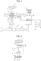
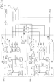
- FIG. 1 is a view illustrative of the whole configuration in a first embodiment, in a case where the motor controller of the present invention is applied to an electric power steering device mounted on a vehicle.
- numeral 1 is a steering wheel, and a steering force exerted to the steering wheel 1, which is operated by a driver, is transmitted to a steering shaft 2.
- the steering shaft 2 includes an input shaft 2a and an output shaft 2b. One end of the input shaft 2a is connected with the steering wheel 1, whereas the other end is coupled through a steering torque sensor 3 with one end of the output shaft 2b.
- the steering force that has been transmitted to the output shaft 2b is transmitted via a universal joint 4 to a lower shaft 5, and is further transmitted to a pinion shaft 7 via the universal joint 6.
- the steering force that has been transmitted to the pinion shaft 7 is transmitted to a tie rod 9 via a steering gear 8, so that turning wheels, not illustrated, are made to turn.
- the steering gear 8 is configured to be a rack and pinion form having a pinion 8a connected with the pinion shaft 7 and a rack 8b engaging with the pinion 8a, and the rotational movement that has been transmitted to the pinion 8a is converted at the rack 8b into the straight travel of the vehicle in the widthwise direction.
- the output shaft 2b of the steering shaft 2 is coupled with a steering assistance mechanism 10 that transmits a steering assistance force to the output shaft 2b.
- the steering assistance mechanism 10 includes a reduction gear 11 having, for example, a worm gear mechanism connected with the output shaft 2b, and a three-phase electric motor 12 operating as the electric motor having, for example, a three-phase brushless motor producing the steering assistance force and connected with the reduction gear 11.
- the steering torque sensor 3 detects steering torque exerted onto the steering wheel 1 and transmitted to the input shaft 2a.
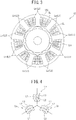
- the steering torque sensor for example, as illustrated in FIG. 2 , converts the steering torque into a twisting angular displacement of a torsion bar 3a arranged between the input shaft 2a and the output shaft 2b, and to convert the twisting angular displacement into an angle difference between an input-side rotational angle sensor 3c arranged at the input shaft 2a side and an output side rotational angle sensor 3b arranged at the output shaft 2b side.
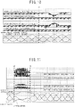
- the three-phase electric motor 12 has, as illustrated in FIG. 3 , a motor configuration of Surface Permanent Magnet (SPM), including a stator 12S having, for example, nine teeth Te, which are magnetic poles formed to inwardly protrude on an inner circumferential surface and forming a slot SL, and a rotor 12R of surface permanent magnet having, for example, six magnetic poles formed to oppose the teeth Te on the inner circumferential of the stator 12S and arranged rotatably.
- SPM Surface Permanent Magnet
- the slot SL of the stator 12S has multiphase motor windings La, Lb, and, Lc of A phase, B phase, and C phase forming the three phases.
- the multiphase motor windings La, Lb and, Lc are, as illustrated in FIG. 4 , for example, configured such that three coil units L1, L2, and L3 are connected to in parallel with one another and the coil units L1 to L3 are wound in three layers in the slot SL.
- One ends of the multiphase motor windings La, Lb, and Lc are connected together to form a star connection, whereas the other ends of the coil units La, Lb, and Lc are connected with a motor controller 20, so that motor drive currents Ia, Ib, and Ic are individually supplied.
- the three-phase electric motor 12 includes a rotational position sensor 13a such as a resolver detecting the rotational position of the motor.
- the detection value from the rotational position sensor 13a is supplied to a motor rotational angle detection circuit 13, and a motor rotational angle ⁇ m is detected in the motor rotational angle detection circuit 13.
- Steering torque T detected by the steering torque sensor 3 and a vehicle speed Vs detected by a vehicle speed sensor 21 are input into the motor controller 20, and in addition, a motor rotational angle ⁇ m output from the motor rotational angle detection circuit 13 is input into the motor controller 20.
- a direct current is input into the motor controller 20 from a battery 22 operating as a direct current voltage source.
- the motor controller 20 includes a control operation device 31 operates a motor current instruction value, first and second motor drive circuits 32A and 32B configured with hardware into which three-phase motor voltage instruction values V1* and V2* output from the control operation device 31 are individually input, and first and second motor current cutoff units 33A and 33B respectively arranged between the output sides of the first and second motor drive circuits 32A and 32B and the first and second multiphase motor windings La to Lc of the three-phase electric motor 12.
- the steering torque T detected by the steering torque sensor 3 and the vehicle speed V detected by vehicle speed sensor 21, as illustrated in FIG. 1 are input into the control operation device 31.
- the motor rotational angle ⁇ m output from the motor rotational angle detection circuit 13 is input into the control operation device 31, and motor currents Iad to Icd to energize the coils L1 to L3 of respective multiphase motor windings La to Lc of the three-phase electric motor 12 output from current detection circuits 39A and 39B, as will be described below are also input into the control operation device 31.
- the control operation device 31 includes a steering assistance current instruction value operation unit 34 calculates a steering assistance current instruction value I*, a compensation control operation unit 35 compensates the steering assistance current instruction value I* calculated by the steering assistance current instruction value operation unit 34 based on an angular velocity ⁇ e and angular acceleration a, and a d-q axis current instruction value operation unit 37 calculates a d-q axis current instruction value based on a compensated torque instruction value I*' that has been compensated by the compensation control operation unit 35, and to convert the calculation result into a three-phase current instruction value.
- the steering assistance current instruction value operation unit 34 refers to a steering assistance current instruction value calculation map illustrated in FIG. 7 based on the steering torque Ts and the vehicle speed Vs, and to calculate the steering assistance current instruction value I*, which is a current instruction value.
- the steering assistance current instruction value calculation map as illustrated in FIG. 7 , includes characteristic diagrams represented by parabolic curves with the steering torque Ts being taken as the horizontal axis and the steering assistance current instruction value I* being taken as the vertical axis.
- the steering assistance current instruction value operation unit 34 calculates the steering assistance current instruction value I* by referring to a normal-time current instruction value calculation curve Lno represented as a solid line of FIG. 7 that is predetermined based on the steering torque T and the vehicle speed V.
- the steering assistance current instruction value operation unit 34 calculates the steering assistance current instruction value I* by referring to an abnormal-time current instruction value calculation curve Lab represented as a dotted line of FIG. 7 that is predetermined based on the steering torque T and the vehicle speed V, when the coil of the three-phase electric motor 12 is abnormal by its disconnection.
- the abnormal-time current instruction value calculation curve Lab has the increased gain with respect to the steering assistance current instruction value I* calculated as the normal-time current instruction value calculation curve Lno.
- the compensation control operation unit 35 compensates a convergence torque compensation value of compensating a convergence of a yaw rate based on, for example, the motor angular velocity ⁇ e and a corresponding torque amount generated by inertia of the electric motor 12 based on the motor angular velocity a, estimates a torque compensation value for preventing a degradation of the inertia feeling of or the control response property, and calculates a self-aligning torque (SAT) compensation value for compensation, so as to add all together and calculate an instruction value compensation value Icom.
- SAT self-aligning torque
- the compensation control operation unit 35 adds at an adder 36 the calculated instruction value compensation value Icom to the steering assistance current instruction value I* output from the steering assistance current instruction value operation unit 34, calculates a compensated current instruction value I*', and outputs the compensated current instruction value I*' to the d-q axis current instruction value operation unit 37.
- the d-q axis current instruction value operation unit 37 includes a d-axis target current calculation unit 37a, an induced voltage model calculation unit 37b, a q-axis target current calculation unit 37c, and a two/three-phase converter 37d.
- the d-axis target current calculation unit 37a calculates a d-axis target current Id* based on the compensated steering assistance current instruction value I*' and the motor angular velocity ⁇ e.
- the induced voltage model calculation unit 37b calculates a d-axis EMF component ed( ⁇ ) of a d-q axis induced voltage model EMF (Electro Magnetic Force) component ed( ⁇ ) and a q-axis EMF component eq( ⁇ ) based on the motor rotational angle ⁇ and the motor angular velocity ⁇ e.
- EMF Electro Magnetic Force
- the q-axis target current calculation unit 37c calculates a q-axis target current Iq* based on the d-axis EMF component ed ( ⁇ ) and the q-axis EMF component eq ( ⁇ ) output from the induced voltage model calculation unit 37b, the d-axis target current Id* output from the d-axis target current calculation unit 37a, the compensated steering assistance current instruction value I*', and the motor angular velocity ⁇ e.
- the two/three-phase converter 37d converts the d-axis target current Id* output from the d-axis target current calculation unit 37a and the q-axis target current Iq* output from the q-axis target current calculation unit 37c into three-phase current instruction values Ia*, Ib*, and Ic*.
- control operation device 31 includes a voltage instruction value operation unit 38 that calculates voltage instruction values V1* and V2* for the motor drive circuits 32A and 32B based on the calculated A-phase current instruction value Ia*, the calculated B-phase current instruction value Ib*, and the calculated C-phase current instruction value Ic*, and current detection values Iad, Ibd, and Icd detected by the current detection circuits 39A and 39B.
- the voltage instruction value operation unit 38 subtracts current detection values Iad, Ibd, and Icd from the A-phase current instruction value Ia*, the B-phase current instruction value Ib*, and the C-phase current instruction value Ic* to calculate current deviations ⁇ Ia, ⁇ Ib, and ⁇ Ic, carries out, for example, a PI control operation or a PID control operation on the current deviations ⁇ Ia, ⁇ Ib, and ⁇ Ic, calculates the three-phase voltage instruction values V1* and V2* for the first and second motor drive circuits 32A and 32B, and outputs the calculated three-phase voltage instruction values V1* and V2* to the first and second motor drive circuits 32A and 32B, respectively.
- the three-phase voltage instruction values V1* and V2* are output from an abnormality detection unit 31a, as will be described later, as identical values to each other in the normal state where no abnormality is detected.
- control operation device 31 receives motor-phase voltages V1ma, V1mb, V1mc, V2ma, V2mb, and V2mc detected by motor voltage detection circuits 40A and 40B, which are respectively arranged between the motor drive circuits 32A and 32B and the first and second motor current cutoff units 33A and 33B.
- the control operation device 31 receives upper current detection values IA1d and IB1d respectively output from current detection circuits 39A1 and 39B1 that respectively detect direct currents supplied to inverter circuits 42A and 42B of the first and second motor drive circuits 32A and 32B, and lower current detection values IA2d and IB2d respectively output from current detection circuits 39A2 and 39B2 that respectively detect direct currents from the inverter circuits 42A and 42B to be flown to the ground.
- the control operation device 31 includes an abnormality diagnosis unit 31b including an abnormality detection unit 31a that detects an open failure of the upper arms and a short-circuit failure of the lower arms of field effect transistors (FET) Q1 to Q6 operating as switching elements included in first and second inverter circuits 42A and 42B to be described later, and a disconnection abnormality of any of the coil units L1 to L3 of the phase motor windings La, Lb, and Lc of the three-phase electric motor 12, after the motor-phase voltages Vmla, Vmlb, Vmlc, Vm2a, Vm2b, and Vm2c, the upper current detection values IA1d and IB1d, and the lower current detection values IA2d and IB2d are input into the A/D converter 31c.
- FET field effect transistors
- the abnormality detection unit 31a detects an abnormality as follows.
- the upper current detection value IA1d of the motor drive circuit 32A decreases when the motor drive current Ia of the arm having the open failure is positive. To compensate the decrease, the upper current detection value IB1d of the motor drive circuit 32B will be increased.
- the motor drive circuit 32A or 32B having the open failure is identified by comparing the detected upper current detection values IA1d and IB1d with each other.
- An abnormality detection signal SAa or SAb having a logical value "1" is output to the motor drive circuit 32A or 32B having the open failure.
- the motor current largely fluctuates, as illustrated in FIG. 11 .
- the motor drive current only from the motor drive circuit 32B is supplied to the respective phase motor windings La to Lc of the three-phase electric motor 12, and the motor drive current returns to a stable shape of sine wave. It is therefore possible to continue driving of the three-phase electric motor 12.
- a pulse width modulation (PWM) signal is input into the gate of the field effect transistors (FET) of the inverter circuits 42A and 42B, and therefore, the motor drive electric currents Ia to Ic output from the inverter circuits 42A and 42B become rectangular wave signals where the duty ratios are controlled. Therefore, when the instantaneous values of the motor drive electric currents Ia to Ic are detected and the rectangular wave signals being off is simply detected, a regular motor current value will not be presented.
- PWM pulse width modulation
- the upper current detection values IA1d and IB1d are supplied to a peak-hold circuit holding the peak values for more than a period as long as one cycle of the pulse width modulation signal. By holding the peak values, the peak (maximum) values of the upper current detection values IA1d and IB1d are detected promptly and accurately.
- the disconnection of the coil unit can be detected by monitoring a change in the motor-phase resistance value, because the resistance value varies depending on the disconnection of any one of the coil units L1 to L3.
- a motor-phase resistance R increases from (1/3)*Rc to (1/2)*Rc, where R is a resistance value for each of the coil units L1 to L3.
- Vm R*i + Ke* ⁇
- R represents a motor-phase resistance (fixed number)
- i represents a motor-phase current (detection value)
- Ke represents a motor back electromotive voltage fixed number
- ⁇ represents a motor rotational velocity (detection value/operation value).
- the motor-phase resistance value change amount ⁇ R can be represented as the following expression.
- ⁇ R Vm ⁇ Ke * ⁇ / i ⁇ R
- the change amount ⁇ R of the resistance value R for motor can be calculated. Then, when the calculated change amount ⁇ R is smaller than a predetermined threshold, it is determined that such a change amount ⁇ R falls within variations, whereas when the change amount ⁇ R is equal to or larger than the predetermined threshold, the disconnection abnormality of any of the coil units L1 to L3 of the phase motor windings La to Lc can be determined.
- a back electromotive force Ej of the phase motor winding Lj is changed to 2/3 of the normal time by the disconnection abnormality of the coil unit Lk.
- the gain Kj with respect to the motor current instruction value Ij* supplied to the phase motor winding Lj where the disconnection abnormality is detected is increased from "1" of the normal time to "3/2".
- T motor torque
- ⁇ a motor angular frequency
- Ea, Eb and, Ec represent back electromotive voltages of the A-phase, B-phase, and C-phase
- Ia, Ib and, Ic represent motor currents of the A-phase, B-phase, and C-phase, respectively.
- Ej*Ij takes an equal value to that of a case of a normal phase motor winding and a torque change is suppressed so that the torque can be controlled to be constant.
- the first and second motor drive circuits 32A and 32B each include gate drive circuits 41A and 41B that respectively receive the three-phase voltage instruction values V1* and V2* output from the control operation device 31 to form gate signals, and first and second inverter circuits 42A and 42B that respectively receives the gate signals output from the gate drive circuits 41A and 41B.
- each of the gate drive circuits 41A and 41B forms six gate signals, which have been subjected to the pulse width modulation (PWM) based on the voltage instruction values V1* and V2* and a carrier signal Sc of triangular wave, and outputs the gate signals to the inverter circuits 42A and 42B.
- PWM pulse width modulation
- the six PWM gate signals may be commonly generated at the control operation device 31 to be input into the inverter circuits 42A and 42B.
- the gate drive circuit 41A when the abnormality detection signal SAa input from the control operation device 31 is a logical value "0" (normal), the gate drive circuit 41A outputs three gate signals of high level to the motor current cutoff unit 33A, and also outputs the gate signal of high level to the power supply cutoff unit 44A. In addition, when the abnormality detection signal SAa is a logical value "1" (abnormal), the gate drive circuit 41A outputs three gate signals of low level to the motor current cutoff unit 33A at the same time to cut off the motor current, and outputs the gate signal of low level to the power supply cutoff unit 44A to cut off the battery power.
- the gate drive circuit 41B outputs three gate signals of high level to the motor current cutoff circuit 33B, and also outputs the gate signal of high level to the power supply cutoff unit 44B.
- the gate drive circuit 41B outputs three gate signals of low level to the motor current cutoff circuit 33B at the same time to cut off the motor current, and also outputs the gate signal of low level to the power supply cutoff unit 44B to cut off the battery power.
- the first and second inverter circuits 42A and 42B each receive the battery electric currents of a battery 22 via a noise filter 43, the power supply cutoff units 44A and 44B, and the current detection circuits 39A1 and 39B1, and are coupled on the input side with electrolytic capacitors CA and CB for smoothing.
- the first and second inverter circuits 42A and 42B each include six field effect transistors (FET) Q1 to Q6 operating as the switching elements, and three switching arms SWAa, SWAb, and SWAc and three switching arms SWBa, SWBb, and SWBc, in each of which two field effect transistors are connected in series, are connected in parallel.
- FET field effect transistors
- the first and second inverter circuits 42A and 42B each receive gate signals output from the gate drive circuits 41A and 41B at the gate of each of the field effect transistors Q1 to Q6. From connection points of the field effect transistors of the switching arms SWAa, SWAb, and SWAc, and SWBa, SWBb, and SWBc, the A-phase current Ia, the B-phase current Ib, and the C-phase current Ic are electrically conducted via the motor current cutoff units 33A and 33B to the three-phase motor windings La, Lb, and Lc of the three-phase electric motor 12.
- the switching arms SWAa, SWAb, and SWAc, and SWBa, SWBb, and SWBc of the inverter circuits 42A and 42B are respectively connected with the field effect transistors Q2, Q4, and Q6 to be the lower arms, and are grounded through the current detection circuits 39A2 and 39B2, and motor currents I1a to I1c and I2a to I2c are respectively detected by the current detection circuits 39A and 39B.
- the current detection circuits 39A1, 39A2, 39B1, and 39B2 are configured as illustrated in FIG. 8A and FIG. 8B .
- the current detection circuits 39A1 and 39B1, as illustrated in FIG. 9 respectively include current detecting shunt resistances 51A and 51B arranged between the power supply side of the switching arms SWAa to SWAc and SWBa to SWBc and the power supply cutoff units 44A and 44B.
- 8A includes an operational amplifier 39a into which voltages of both ends of the shunt resistances 51A and 51B are input through resistances R2 and R3, and a sample-hold circuit 39s mainly including a noise filter to which an output signal from the operational amplifier 39a is supplied.
- the current detection circuits 39A2 and 39B2 include current detecting shunt resistances 52A and 52B arranged between the grounding side of the switching arms SWAa to SWAc and SWBa to SWBc and the ground.
- Each of the current detection circuits 39A2 and 39B2, as illustrated in FIG. 8B includes an operational amplifier 39a into which voltages of both ends of the shunt resistances 52A and 52B are input into through the resistances R2 and R3, a peak-hold circuit 39p including a noise filter to which an output signal from the operational amplifier 39a is supplied, and a sample-hold circuit 39s including mainly a noise filter to which an output signal from the operational amplifier 39a is supplied.
- current detection signals IA2d and IB2d output from the sample-hold circuit 39s are supplied to an A/D converter 31c of the control operation device 31.
- peak-hold signals IA3d and IB3d of the current detection values output from the peak-hold circuit 39p are supplied to the A/D converter 31c and overcurrent-time cutoff circuits 70A and 70B and current bypass circuits 80A and 80B, as will be described later.
- the motor current cutoff unit 33A includes three field effect transistors QA1, QA2, and QA3 for cutting off the current.
- the source of the field effect transistor QA1 is connected with a connection point of the transistors Q1 and Q2 of the switching arm SWAa of the first inverter circuit 42A through the motor voltage detection circuit 40A, and the drain of the field effect transistor QA1 is connected with the A-phase motor winding La of the three-phase motor windings L1.
- the source of the field effect transistor QA2 is coupled with a connection point of the transistors Q3 and Q4 of the switching arm SWAb of the first inverter circuit 42A through the motor voltage detection circuit 40A, and the drain of the field effect transistor QA2 is connected with the three-phase motor winding Lb.
- the source of the field effect transistor QA3 is coupled with a connection point of the transistors Q5 and Q6 of the switching arm SWAc of the first inverter circuit 42A through the motor voltage detection circuit 40A, and the drain of the field effect transistor QA3 is connected with the three-phase motor winding Lc.
- the motor current cutoff circuit 33B includes three field effect transistors QB1, QB2, and QB3 used for cutting off the current.
- the source of the field effect transistor QB1 is connected with a connection point of the transistors Q1 and Q2 of the switching arm SWBa of the second inverter circuit 42B through the motor voltage detection circuit 40B, and the drain of the field effect transistor QB1 is connected with the three-phase motor winding La.
- the source of the field effect transistor QB2 is connected with a connection point of the transistors Q3 and Q4 of the switching arm SWBb of the second inverter circuit 42B through the motor voltage detection circuit 40B, and the drain of the field effect transistor QB2 is connected with the three-phase motor winding Lb.
- the source of the field effect transistor QB3 is connected with a connection point of the transistors Q5 and Q6 of the switching arm SWBc of the second inverter circuit 42B through the motor voltage detection circuit 40B, and the drain of the field effect transistor QB3 is connected with the three-phase motor winding Lc.
- the field effect transistors QA1 to QA3 and QB1 to QB3 of the motor current cutoff units 33A and 33B are connected with the anodes of the parasitic diodes D in an identical direction on the inverter circuits 42A and 42B side.
- each of the power supply cutoff units 44A and 44B respectively includes a parallel circuit including a field effect transistor (FET) QC and an FET QD, and a parasitic diode.
- FET field effect transistor
- the drains of the field effect transistors QC and QD are connected with a battery 22 through the noise filter 43, and the sauces of the field effect transistors QC and QD are respectively connected with the inverter circuits 42A and 42B.
- the configurations of the power supply cutoff units 44A and 44B are not limited to the above ones. As illustrated in FIG. 9 , two power supply cutoff units 44A and 44A', and 44B and 44B' may be connected in series with each other so that the parasitic diodes are arranged in opposite directions.
- the control operation device 31 of the motor controller 20 is in a non-operating state. Therefore, the steering assistance control process to be carried out by the control operation device 31 and the abnormality monitoring process stop. Thus, the electric motor 12 stops the operation, and the output of the steering assistance force to the steering assistance mechanism 10 stops.
- the d-axis current instruction value Id* and the q-axis current instruction value Iq* are calculated based on the calculated steering assistance current instruction value I* and the motor electric angle ⁇ e input from the motor rotational angle detection circuit 13.
- the A-phase current instruction value Ia*, the B-phase current instruction value Ib* and the C-phase current instruction value Ic* are calculated by carrying out the two/three-phase conversion process on the calculated d-axis current instruction value Id* and the q-axis current instruction value Iq*.
- the current deviations ⁇ Ia, ⁇ Ib, and ⁇ Ic with respect to the phase current detection values Iad, Ibd, and Ibc are calculated from the phase current instruction value Ia*, Ib*, and Ic* and the phase current detection values IA1d and IB1d detected by the current detection circuits 39A and 39B. Then, the target voltage instruction values Va*, Vb*, and Vc* are calculated by carrying out the PI control process or the PID control process on the calculated current deviations ⁇ Ia, ⁇ Ib, and ⁇ Ic.
- the calculated target voltage instruction values Va*, Vb*, and Vc* are respectively output as the voltage instruction values V1* and V2* to the gate drive circuits 41A and 41B in the first and second motor drive circuits 32A and 32B.
- the control operation device 31 outputs the abnormality detection signals SAa and SAb of logic value "0" to the gate drive circuits 41A and 41B.
- the gate drive circuits 41A and 41B respectively output three gate signals of high level to the motor current cutoff units 33A and 33B.
- the field effect transistors QA1 to QA3 and QB1 to QB3 of the motor current cutoff units 33A and 33B are in the on state, and the inverter circuits 42A and 42B and the three-phase motor windings L1 and L2 of the three-phase electric motors 12 turn in the electrically conducting state, so that electrically conducting control for the three-phase electric motor 12 is enabled.
- the gate signals of high level are output from gate drive circuits 41A and 41B to the power supply cutoff units 44A and 44B.
- the field effect transistors QC and QD of the power supply cutoff units 44A and 44B are in the on state, and the direct currents from the battery 22 are supplied to inverter circuits 42A and 42B through the noise filter 43.
- the gate drive circuits 41A and 41B respectively form the gate signals by carrying out pulse width modulation based on the voltage instruction values V1* and V2* input from the control operation device 31. Then, the formed gate signals are respectively supplied to the gates of the field effect transistors Q1 to Q6 of the inverter circuits 42A and 42B.
- the steering wheel 1 is steered in the vehicle stop state or the vehicle travel start state, that is, if so-called stationary steering is done, the steering torque Ts becomes larger.
- a large steering assistance current instruction value I* is calculated, and in accordance with this, large voltage instruction values V1* and V2* are respectively supplied to the gate drive circuits 41A and 41B.
- the gate signals having duty ratios corresponding to the large voltage instruction values V1* and V2* are respectively output from the gate drive circuits 41A and 41B to the inverter circuits 42A and 42B.
- the A-phase current I1a, the B-phase current I1b, and the C-phase current I1c and the A-phase current 12a, the B-phase current I2b, and the C-phase current I3c, each having a phase difference of 120 degrees are respectively output from the inverter circuits 42A and 42B.
- the outputs are supplied to the three-phase motor windings La to Lc of the three-phase electric motor 12 through the field effect transistors QA1 to QA3 and QB1 to QB3, respectively corresponding to the phases of the motor current cutoff units 33A and 33B.
- the electric motor 12 is driven for rotation, a large steering assistance force corresponding to the target steering assistance current value I* depending on the steering torque Ts is produced, and the steering assistance force is transmitted through the reduction gear 11 to the output shaft 2b. It is therefore possible to steer the steering wheel 1 with a light steering force.
- the steering assistance current instruction value calculated in accordance with the vehicle speed Vs becomes lower than that at the time of the stationary steering, and the electric motor 12 generates the steering assistance force that is appropriately decreased depending on the steering torque Ts and the vehicle speed Vs.
- the abnormality detection signal SAa is kept at the logical value "0"
- the abnormality detection signal SAb is the logical value "1”. Therefore, driving of all the six gates of the inverter circuit 42B is turned off, and in addition, the three gate signals of low level are output to the motor current cutoff circuit 33B from the gate drive circuit 41B of the motor drive circuit 32B at the same time, and further, the gate signal of low level is output to the power supply cutoff units 44B.
- the field effect transistors QB1 to QB3 of the respective phases are in the off state, and electrical conduction to the three-phase motor windings La to Lc of the three-phase electric motor 12 is cut off.
- the field effect transistor QD is controlled to turn in the off state, and electrically conducting path between the battery 22 and the second inverter circuit 42B is cut off.
- the steering assistance torque same as that at the normal time is generated by the three-phase electric motor 12 and the generated steering assistance torque is transmitted through the reduction gear 11 to the output shaft 2b, so that the steering assistance performance that compares well with that at the normal time can be brought out.
- an alarm signal Swa is output to an alarm circuit 50.
- the abnormality of the motor drive circuit 32B is informed to a driver so as to encourage the driver to stop at the nearest service station.
- the inverter circuit 42A which is one of the first and second inverter circuits 42A and 42B of the first and second motor drive circuits 32A and 32B, as described above based on FIG. 10
- the motor drive current Ia of the arm at which the open failure has occurred becomes positive
- the upper current detection value IA1d of the motor drive circuit 32A decreases, and to make up for this, the upper current detection value IB1d of the motor drive circuit 32B increases. Therefore, a difference is generated between the upper current detection value IA1d and the upper current detection value IB1d, so that the open failure occurring at the decreasing side of the upper current detection value can be determined.
- the respective phase switches QA1 to QA3 of the motor current cutoff unit 33A of the motor drive circuit 32A are controlled to be in the off state, and in addition, the power supply cutoff unit 44A is controlled to be in the off state.
- Driving of the motor drive circuit 32A stops, individual control of the three-phase electric motor 12 by the motor drive circuit 32B that is normal continues, as described above, and the steering assistance control that compares well with that at the normal time continues. At this timing, alarming is informed to a driver so as to encourage the driver to stop at the nearest service station.
- the abnormality detection unit 31a of the control operation device 31 calculates the motor-phase resistance value change amount ⁇ R of each phase by carrying out an operation of the above expression (3) based on the respective motor-phase voltages Vmla to Vmlc and Vm2a to Vm2c detected by the motor voltage detection circuits 40A and 40B arranged on the output sides of the motor drive circuits 32A and 32B, the motor rotational velocity ⁇ calculated by carrying out the differential operation on the motor rotational angle ⁇ m detected by the motor rotational angle detection circuit 13 or detected by separately providing a motor rotational velocity detection circuit, and motor-phase electric currents ia to ic obtained by adding the respective motor-phase electric currents i1a to i1c and i2a to i2c detected by the current detection circuits 39A and 39B, for each phase.
- each motor-phase resistance value change amount ⁇ R of each motor-phase that has been calculated is smaller than a predetermined threshold ⁇ Rn, it is determined to fall within the variation.
- the motor-phase resistance value change amount ⁇ R is equal to or larger than the predetermined threshold ⁇ Rn, the disconnection abnormality at any of the coil units L1 to L3 of the motor windings La to Lc of the three-phase electric motor 12 can be detected correctly.
- the characteristic curve of the steering assistance current instruction value calculation map to be referred by the steering assistance current instruction value operation unit 34 is changed to the characteristic curve Lab at the abnormality occurrence from the characteristic curve Lno at the normal time.
- the steering assistance current instruction value I* with respect to the value of the steering torque T detected by the steering torque sensor 3 becomes as much as two time the characteristic curve Lno at the normal time.
- the steering assistance current instruction value I*' which has been obtained by compensating the steering assistance current instruction value I* by the compensation control operation unit 35 with the compensation value Icom, is supplied to the d-q axis current instruction value operation unit 37. After being converted into the d-q axis current instruction value, it is subjected to the two-phase/three-phase conversion and the target current instruction values Ia*, Ib*, and Ic* are calculated.
- These target current instruction values Ia*, Ib*, and Ic* are output by the voltage instruction value operation unit 38, as the voltage instruction values V1* and V2*, to the gate drive circuits 41A and 42B the motor drive circuits 32A and 32B.
- the motor drive electric currents Ia, Ib, and Ic for compensating the torque decrease by the disconnection of the coil unit Lk of the phase motor winding Lj is supplied to the phase motor windings La, Lb, and Lc of the three-phase electric motor 12, and in addition, a change suppression effect of the steering torque that has been higher enables suppression of a strange steering feel.
- Ej* Ij in the expression (4) representing input and output energy relationship formula of the above-described three-phase electric motor 12 has a value equal to that of the case of a normal phase motor winding, and the torque change is suppressed so that torque constant control can be performed. Also in this case, alarming is given by the alarm circuit 50 to inform the driver of the disconnection abnormality at the coil unit of the three-phase electric motor 12.
- the motor drive circuits to become the motor current supply systems for supplying the motor current to the multiphase electric motor are configured to be multiplexed, and in addition, the respective motor windings of the multiphase electric motor are configured such that plural coil units are connected in parallel with each other.
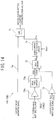
- the present invention is not limited to the above configurations. As illustrated in FIG. 12 , a gain used to calculate the back electromotive voltage compensation value depending on a decrease in the motor back electromotive voltage (EMF) may be decreased.
- the motor control system for one phase of the three-phase electric motor 12, as illustrated in FIG. 12 includes a subtracter 61 that operates a deviation between the current instruction value i* and the phase motor current i, and a current feedback controller 62 to which the current deviation ⁇ i output from the subtracter 61 is supplied. Then, the motor voltage output from the current feedback controller 62 is supplied to an adder 63, and the output from the adder 63 is supplied to the three-phase electric motor 12. Hence, the motor current i is output, and is then supplied to the subtracter 61.
- the motor rotational velocity ⁇ and the motor-phase angle (electric angle) ⁇ e are supplied to a back electromotive voltage (EMF) compensator 64.
- the back electromotive voltage (EMF) compensator 64 calculates the back electromotive voltage EMF based on the motor rotational velocity ⁇ and the motor-phase angle ⁇ e, the compensation gain Kc is multiplied by the calculated back electromotive voltage compensation value EMF to obtain the back electromotive voltage compensation value EMFc.
- the back electromotive voltage compensation value EMFs is supplied to a subtracter 65 to which the back electromotive voltage EMF has been supplied, and the subtraction output from the subtracter 65 is supplied to the adder 63.
- the subtraction of the motor back electromotive voltage (EMF) by the subtracter 65 is in fact a physical phenomenon generated in a motor, and the subtracter 65 does not exist in fact.
- the back electromotive voltage compensator 64 sets the gain Kc to "1", when the abnormality detection signal SAc used for detecting the disconnection abnormality of any of the coil units L1 to L3 by the above-described abnormality detection unit 31a is a logical value "0" representing the absence of abnormality, and the back electromotive voltage compensator 64 sets the gain Kc to "2/3", when the abnormality detection signal SAc is a logical value "1" representing the presence of abnormality.
- the abnormality detection signal SAc input into the back electromotive voltage compensator 64 from the abnormality detection unit 31a is a logical value "0" and the gain Kc is set to "1". Therefore, the back electromotive voltage EMF, which is calculated by the back electromotive voltage compensator 64 by using the motor rotational velocity ⁇ and the motor-phase angle ⁇ e, is output to the subtracter 65 without change, as the back electromotive voltage compensation value EMFc.
- the back electromotive voltage EMF generated at the motor winding Lk of the three-phase electric motor 12 is offset by the back electromotive voltage compensation value EMFc, and the motor current i of the three-phase electric motor 12 is controlled to be a value according to the current instruction value i*.
- the abnormality detection signal SAc of a logical value "1" is supplied from the abnormality detection unit 31a to the back electromotive voltage compensator 64. Therefore, the gain Kc is set to "2/3" by the back electromotive voltage compensator 64, and the back electromotive voltage compensation value EMFc becomes 2/3 the back electromotive voltage compensation value EMFc of the normal time.
- the back electromotive voltage EMF to be generated is 2/3 the back electromotive force EMF of the normal time, and the back electromotive voltage EMF is offset by the back electromotive voltage compensation value EMFc at the subtracter 65.
- the alarm circuit 50 gives alarming to inform the driver of the coil unit disconnection abnormality of the three-phase electric motor 12.
- the phase motor current ij may be changed depending on the change of the back electromotive force Ej, and in addition, the gain to calculate the back electromotive voltage compensation value may be decreased depending on the decrease of the motor back electromotive voltage (EMF). In this case, better effectiveness can be obtained.
- the cutoff control of the motor current cutoff unit 33A or 33B is carried out by a software process of the control operation device 31.
- the motor current cutoff units 33A and 33B and the power supply cutoff units 44A and 44B carry out the cutoff operation on a hardware basis.
- current detection values IA3d and IB3d detected by peak-hold circuits 39p of the current detection circuits 39A and 39B are respectively supplied to overcurrent-time cutoff circuits 70A and 70B configured with hardware, and the overcurrent-time cutoff circuits 70A and 70B respectively carry out the cutoff operation of the motor current cutoff units 33A and 33B and the power supply cutoff units 44A and 44B.
- Each of the overcurrent-time cutoff circuits 70A and 70B is configured as illustrated in FIG. 14 . That is, for example, the motor drive circuit 32A will be described.
- An AND circuit 71 is arranged at a gate signal supply line Lg between the gate drive circuit 41A and the motor current cutoff unit 33A, which have been described above.
- the current detection value IA3d output from the peak-hold circuit 39p of the current detection circuit 39A2 is supplied to one of input sides of a maximum value selection circuit 72, and a diagnosis signal Sd1 output from the control operation device 31 is input into the other one of the input sides of the maximum value selection circuit 72 through an amplifier 73.
- the maximum value selection circuit 72 selects the current detection value IA3d when the diagnosis signal Sd1 is not input, and selects the diagnosis signal Sd1 when the diagnosis signal Sd1 is input.
- the control operation device 31 alternately outputs the diagnosis signals Sd1 and S2d, for example, by a timer interruption process, at every predefined time, for example, every minute. Alternatively, the state where the steering assistance is not performed by the motor is detected and the diagnosis signals Sd1 and Sd2 are output.
- a selection signal Ss output from the maximum value selection circuit 72 is supplied to an overcurrent determination circuit 74 configured to determine the overcurrent state or not.
- an overcurrent determination signal Soc of low level is output, whereas when the selection signal Ss is smaller than the overcurrent threshold Voct, an overcurrent determination signal Soc of high level is output.
- Such an overcurrent detection signal Soc is supplied to the other one of the input sides of the AND circuit 71.
- Ioct Ioct x Rs
- 150A is set as the overcurrent threshold Ioct
- 1 m ⁇ is set as the resistance Rs of the current detection resistances 52A and 52B.
- the maximum value selection circuit 72 selects the current detection value IA3d detected by the peak-hold circuit 39p of the current detection circuit 39A2, and supplies the selected value to the overcurrent determination circuit 74 as the selection signal Ss.
- the current detection value IA3d detected by the peak-hold circuit 39p of the current detection circuit 39A2 is not equal to or higher than the overcurrent threshold Voct, and the overcurrent determination signal Soc of high level is output to the AND circuit 71 from the overcurrent determination circuit 74.
- control operation device 31 outputs the gate signal Sg of high level to the AND circuit 71, when the power is turned on and no abnormality of the motor drive circuit 32A is detected by the abnormality detection unit 31a, whereas the control operation device 31 outputs the gate signal Sg of low level, when an abnormality of the motor drive circuit 32A is detected.
- the gate signal Sg of high level is output from the control operation device 31, and in addition, the current detection value IA3d detected by the peak-hold circuit 39p of the current detection circuit 39A2 is not equal to or higher than the overcurrent threshold Voct.
- the overcurrent determination signal Soc of high level is output to the AND circuit 71 from the overcurrent determination circuit 74. Therefore, the output signal from the AND circuit 71 is high level and the field effect transistors QA1 to QA3 of the motor current cutoff unit 33A are controlled to the on state, and the motor currents Ia to Ic output from the motor drive circuit 32A are supplied to the phase motor windings La to Lc of the three-phase electric motor 12.
- the three-phase electric motor 12 generates the steering assistance force corresponding to the steering torque.
- a short-circuit current flows at a time when the field effect transistors Q1, Q3, and Q5, to be the upper arms where a short-circuit failure occurs are in the on state.
- the short-circuit current is detected by the current detection circuit 39A, and is supplied to the overcurrent determination circuit 74 through the maximum value selection circuit 72.
- the overcurrent determination signal Soc of low level is output from the overcurrent determination circuit 74 to the AND circuit 71. Therefore, the output from the AND circuit 71 becomes the low level, and the field effect transistors QA1 to QA3 for the current cutoff of the motor current cutoff unit 33A and the field effect transistor QC of the power supply cutoff unit 44A are controlled to be in the off state.
- the motor currents Ia to Ic output to the three-phase electric motor 12 from the motor drive circuit 32A are cut off.
- the cutoff state continues and the current detection value IA1d at the current detection circuit 39A1 and the current detection value IA2d at the current detection circuit 39A2 are zero. It is thus possible for the abnormality detection unit 31a to detect the value as an abnormality of the motor drive circuit 32A.
- the overcurrent state can be detected immediately by the overcurrent-time cutoff circuits 70A and 70B configured with hardware.
- the overcurrent state is detected, the cutoff operation of the motor current cutoff unit 33A or 33B can be carried out immediately, and the cutoff operation of the power supply cutoff unit 44A or 44B can be carried out immediately, too.
- Such an overcurrent state enables to certainly prevent the damage, caused by the overcurrent, of the field effect transistors Q1 to Q6 of the motor drive circuit 32A or 32B.
- the diagnosis signal Sd including the diagnosis signals Sd1 and Sd2 to be a value larger than an overcurrent threshold Ioct through the amplifier 73 is alternately output to the motor drive circuits 32A and 32B, at every predefined timing from the abnormality diagnosis unit 31b of the control operation device 31 after the power is turned on, or at a timing when the state where the steering assistance carried out by the motor is not being operated is detected.
- the diagnosis signal Sd is selected by the maximum value selection circuit 72, and is supplied to the overcurrent determination circuit 74.
- the overcurrent determination circuit 74 as the diagnosis signal Sd to be input is larger than the overcurrent threshold Ioct, the overcurrent determination signal Soc of low level is output to the AND circuit 71. Therefore, the output from the AND circuit 71 becomes the low level, the motor current cutoff unit 33A or 33B is controlled to be in the cutoff state, and the power supply cutoff unit 44A or 44B is controlled to be in the cutoff state.
- the diagnosis signal Sd is alternately supplied to the motor drive circuits 32A and 32B from the control operation device 31 at every predefined time. Therefore, the motor drive circuit 32A or 32B to which the diagnosis signal Sd is not supplied is capable of continuing the normal steering assistance control, so that a strange feel to be given to the driver during the diagnosis can be prevented. Alternatively, also by supplying the diagnosis signal Sd in the state where the steering assistance carried out by the motor is not being operated, a strange feel to be given to the driver can be prevented.
- current bypass circuits 80A and 80B may be arranged between the power supply line and the ground, as illustrated in FIG. 15 .
- Each of the current bypass circuits 80A and 80B has a series circuit of a field effect transistor 81 and a protection resistance 82 arranged between the power supply line Lp, over which the power from the battery 22 of the motor drive circuits 32A and 32B is supplied, and the ground.
- the resistance value of the protection resistance 82 is set such that the current is so set as to the amount by which the field effect transistor 81 is not damaged when the field effect transistor 81 is in the on state and the overcurrent flows.
- the overcurrent determination signal Soc of the overcurrent determination circuit 74 having a similar configuration to that of FIG. 14 is input to the gate of the field effect transistor 81.
- the overcurrent determination circuit 74 supplies the overcurrent determination signal Soc of high level to the base of the field effect transistor 81 and turns the field effect transistor 81 to be in the on state.
- the overcurrent determination circuit 74 supplies the overcurrent determination signal Soc of low level to the base of the field effect transistor 81 and turns the field effect transistor 81 to be in the off state.
- the overcurrent determination circuit 74 determines that overcurrent is not occurring, the current bypass circuits 80A and 80B output the overcurrent determination signal Soc of low level to turn the field effect transistor 81 to be in the off state.
- the battery current supplied from the battery 22 is supplied to the motor drive circuits 32A and 32B, without being bypassed or reduced.
- the overcurrent determination circuit 74 determines that the overcurrent state is occurring, the current bypass circuits 80A and 80B output the overcurrent determination signal Soc of high level to turn the field effect transistor in the on state. Therefore, the current supplied from the battery 22 flows through the current bypass circuits 80A and 80B to the ground through a current protection resistance 83.
- the current amount to be supplied to the motor drive circuit 32A or 32B is reduced to certainly prevent the damage of the field effect transistor 81 and the field effect transistors Q1 to Q6 of the motor drive circuit 32A or 32B.
- overcurrent suppression units 85A and 85B including protection resistances or protection coils may be provided on the three-phase electric motor 12 side of the motor current cutoff units 33A and 33B in the motor drive circuits 32A and 32B.
- the overcurrent suppression units 85A and 85B, as illustrated in FIG. 17 may be provided for both of the motor drive circuits 32A and 32B.
- one set of overcurrent suppression units 85C may be arranged between the motor current cutoff units 33A and 33B.
- the overcurrent suppression units 85A and 85B when a short-circuit abnormality occurs at one of the motor drive circuits 32A and 32B, the motor currents Ia to Ic flow into the motor drive circuit 32B (or 32A) where the short-circuit abnormality occurs from the motor drive circuit 32A (or 32B) that is normal, so that an affect given to the motor current to be supplied to the three-phase electric motor 12 can prevented with certainty.
- the motor drive circuits 32A and 32B are provided with the overcurrent suppression units 85A and 85B individually, circuit constants of the motor drive circuit 32A and 32B can be matched with each other. Hence, the circuit design is made easily without the need to consider an imbalance of the circuit constants at the time of designing the motor drive circuits 32A and 32B.
- the current detection units of the current detection circuits 39A and 39B respectively include the shunt resistances 52A and 52B arranged between the connection point on the ground side of the switching arms SWAa to SWAc and SWBa to SWBc, and the ground.
- the voltages on both ends of the respective shunt resistances 52A and 52B are supplied to the operational amplifier 39a, an output signal from the operational amplifier 39a is subject to the sample-holding by a sample-hold circuit 39c through a noise filter 39b, and the sample-hold signal is converted into a digital signal by an A/D converter 31c.
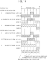
- FIG. 19 illustrates an example of a relationship between the sampling period at the A/D converter 31c and pulse width modulation signals of the field effect transistors Q1 to Q6 included in the motor drive circuits 32A and 32B.
- the switching arms SWAa and SWBa be the largest duty phases
- the switching arms SWAb and SWBb be intermediate duty phases
- the switching arms SWAc and SWBc be the smallest duty phases.
- the field effect transistor Q1 to be an upper arm is inverted to the on state from the off state at the start time point t0 of one cycle (for example, 50 psec) of the pulse width modulation signal. Then, at the time point t2, the field effect transistor Q3 to be an upper arm of the switching arms SWAb and SWBb to be the intermediate duty phases is inverted to the on state from the off state. Subsequently, at the time point t3, the field effect transistor Q5 to be an upper arm of the switching arms SWAc and SWBc to be the smallest duty phases is inverted to the on state from the off state.
- the field effect transistor Q5 is inverted to the off state from the on state at the time point t4, and the field effect transistor Q3 is inverted to the off state from the on state at the time between points t4 and t5, then the field effect transistor Q1 is inverted to the off state from the on state at time point t5.
- the current detection values IA2d and IB2d output from the sample-hold circuit 39s are sampled and converted into digital signals in a sampling period SP1 between the time points t0 and t1 while the field effect transistor, for example, Q1 only on the upper arm side of a single phase is in the on state, and in a sampling period SP3 between the time points t2 and t3 while the field effect transistor on the upper arm side of a double phase is in the on state.
- the switching arms SWAa to SWAc and SWBa to SWBc to be the largest duty phases, the intermediate duty phases, and the smallest duty phases during one cycle of the pulse width modulation signal sequentially change.
- an open failure of each of the field effect transistors Q1 to Q6 can be detected by comparing the digital current detection values IA1d and IB1d and by further comparing IA2d and IB2d based on the sample-hold outputs, which have been sampled in the sampling periods SP1 and SP3, from the A/D converter 31c.
- the steering assistance torque is generated at the three-phase electric motor 12, but the three-phase electric motor 12 itself does not rotate.
- the largest duty phase, the intermediate duty phase, and the smallest duty phase in one cycle of the pulse width modulation signal are fixed in the state of FIG. 19 , for example.
- the sampling period SP4 between the time points t3 and t4 and the sampling period SP6 between the time points t5 and t6 are added to the sampling periods SP1 and SP3 at the A/D converter 31c, so that the digital current detection value is obtainable in the on state of the field effect transistor to be the lower arm of the largest duty phase and in the on state of the field effect transistor to be the upper arm of the smallest duty phase.
- the digital current detection values IA1d and IB1d or IA2d and IB2d detected by the current detection circuits 39A1 and 39B1 or 39A2 and 39B2 it is possible to certainly detect the open failure of the field effect transistor to be the lower arm of the largest duty phase and the field effect transistor to be the upper arm of the smallest duty phase.
- the sampling periods SP4 and SP6 in an A/D conversion circuit 39d can be added when the steering wheel 1 is in the steering holding state, that is, when there is no change or a slight change in the rotational position detection value from the rotational position sensor 13a.
- an instruction value correction unit 75 illustrated in FIG. 20 may output a slight movement correction value to the adder 36 to slightly move the three-phase electric motor 12 clockwise and counterclockwise to an extent not to give the driver a strange feel, so that the rotation stop state of the three-phase electric motor 12 by holding the steering does not occur.
- the abnormality diagnosis unit 31b may detect an operation abnormality of the motor current cutoff units 33A and 33B of the motor drive circuits 32A and 32B and the power supply cutoff units 44A and 44A', and 44B and 44B'.
- an input voltage detection circuit 100A detects an input voltage VR1 is arranged between the shunt resistance 51A and the field effect transistors Q1, Q3, and Q5.
- an input voltage detection circuit 100B detects an input voltage VR2 is arranged between the shunt resistance 51B and the field effect transistors Q1, Q3, and Q5.
- the abnormality diagnosis unit 31b of the control operation device 31, as illustrated in FIG. 22 includes a current cutoff diagnosis unit 101 and a drive state determination unit 102.
- the current cutoff diagnosis unit 101 includes a first diagnosis unit 101a, a second diagnosis unit 101b, and a third diagnosis unit 101c.
- the first diagnosis unit 101a also serves as a motor current cutoff diagnosis unit, and temporarily turns the motor current cutoff unit 33A or 33B to be in the cutoff state to diagnose an operation state of the motor current cutoff unit 33A or 33B.
- the second diagnosis unit 101b temporarily turns the power supply cutoff units 44A and 44A', or 44B and 44B' to be in the cutoff state to diagnose operation states of the power supply cutoff unit 44A and 44A', or 44B and 44B'.
- the third diagnosis unit 101c temporarily turns the motor current cutoff unit 33A or 33B and the power supply cutoff units 44A and 44A' or 44B and 44B' to be in the cutoff state to diagnose operation states of the motor current cutoff unit 33A or 33B and the power supply cutoff units 44A and 44A' or 44B and 44B'.
- the abnormality diagnosis unit 31b of the control operation device 31, as illustrated in FIG. 23 carries out a current cutoff diagnosis process illustrated in FIG. 23 as a timer interruption process at every predefined time (for example, one second), in driving and controlling the three-phase electric motor.
- step S1 it is determined whether or not a predefined period (for example, one minute) has passed from the previous diagnosis cutoff diagnosis process is finished without doing anything.
- a predefined period for example, one minute
- step S2 a high torque state where the motor currents Ia to Ic are flown across the three-phase electric motor 12, or a low torque state where the motor current is near "0" is determined.
- the high torque state is determined when the absolute value of the current instruction value I* is equal to or larger than a predefined value, the absolute value of the maximum value of the phase current instruction values Ia* to Ic* is equal to or larger than a predefined value, and the current detection values Iad to Icd are equal to or larger than a predefined value. Otherwise, the low torque state is determined.
- step S2 When the determination result of step S2 is the high torque state where the motor currents Ia to Ic flow, the process goes to step S3 in order to carry out a motor current cutoff unit current diagnosis process to diagnose an operation state of the motor current cutoff unit in the motor drive circuit 32A based on the upper current detection value IA1d and the lower current detection value IA2d. Then, the process goes to step S4.
- step S4 a power supply cutoff unit current diagnosis process is carried out to diagnose operation states of the power supply cutoff units 44A and 44A' in the motor drive circuit 32A based on the upper current detection value IA1d and the lower current detection value IA2d. Then, the process goes to step S5.
- step S5 a motor current cutoff unit current diagnosis process is carried out to diagnose an operation state of the motor current cutoff unit in the motor drive circuit 32B based on the upper current detection value IB1d and the lower current detection value IB2d. Then, the process goes to step S6.
- step S6 a power supply cutoff unit current diagnosis process is carried out to diagnose operation states of the power supply cutoff units 44B and 44B' in the motor drive circuit 32B based on the upper current detection value IB1d and the lower current detection value IB2d. Then, the timer interruption process is finished, and the process returns to a predefined main program.
- step S2 The determination result of the above-described step S2 is the low torque state where the motor current does not flow or slightly flows, the process goes to step S7 in order to carry out a current cutoff unit voltage diagnosis process to diagnose operation states of the motor current cutoff unit 33A in the motor drive circuit 32A and the power supply cutoff units 44A and 44A' based on the input voltage VR1 detected by an input voltage detection unit 100A. Then, the process goes to step S8.
- step S8 the current cutoff unit voltage diagnosis process is carried out to diagnose operation states of the motor current cutoff unit 33B in the motor drive circuit 32B and the power supply cutoff units 44B and 44B' based on the input voltage VR2 detected by an input voltage detection unit 100B. Then, the timer interruption process is finished, and the process returns to the predefined main program.
- step S11 each of the field effect transistors QA1 to QA3 of the motor current cutoff unit 33A in the motor drive circuit 32A is controlled to be in the off state, and the process goes to step S12.
- step S12 the upper current detection values IA1d and IA2d of the current detection circuits 39A1 and 39A2 are read to determine a conductive state where the current is flowing or a non-conductive state.
- step S12 When the determination result of step S12 is the non-conductive state, the process goes to step S13. It is determined that the field effect transistors QA1 to QA3 of the motor current cutoff unit 33A are normal, and then the process goes to step S14. Each of the field effect transistors QA1 to QA3 of the motor current cutoff unit 33A are returned to the on state, and then the process goes to step S4 of FIG. 22 .
- step S12 when the determination result of step S12 is the conductive state, the process goes to step S15. It is determined that a circuit-circuit failure occurs at one or more of the field effect transistors QA1 to QA3 of the motor current cutoff unit 33A, and then the process goes to step S16.
- step S16 an abnormal-time process to output the abnormality detection signal SAa of a logical value "1" to the gate drive circuit 41A is carried out in order to turn the field effect transistors Q1 to Q6 of the inverter circuit 42A to be in the off state, turn the field effect transistors QA1 to QA3 of the motor current cutoff unit 33A to be in the off state, and turn the field effect transistors included in the power supply cutoff units 44A and 44A' to be in the off state. Then, the process goes to step S4 of FIG. 23 .
- the steering assistance performance that compares well with that at the normal time can be brought out by using the motor drive circuit 32B that is normal same as the case where an abnormality of the motor drive circuit 32A is detected in the above-described embodiment.
- step S12 is not limited to the above-described operations, it may be determined whether or not the upper current detection value IA1d and the lower current detection value IA2d match each other.
- step S4 in the power supply cutoff unit current diagnosis process of step S4 in FIG. 22 , firstly in step S21, as illustrated in FIG. 25 , the power supply cutoff units 44A and 44A' of the motor drive circuit 32A are controlled to the off state. Then, the process goes to step S22.
- step S22 the upper current detection values IA1d and IA2d of the current detection circuits 39A1 and 39A2 are read to determine the conductive state where the current is flowing or the non-conductive state.
- step S22 When the determination result of step S22 is the non-conductive state, the process goes to step S23 to determine that the field effect transistors included in the power supply cutoff units 44A and 44A' are normal. Then, the process goes to step S24 to return each of the field effect transistors included in the power supply cutoff unit 44A and 44A' to the on state. Then, the process goes to step S5 of FIG. 22 .
- step S22 when the determination result of step S22 is the conductive state, the process goes to step S25 to determine that a short-circuit failure occurs at any one or both of the field effect transistors of the power supply cutoff units 44A and 44A'. Then, the process goes to step S26.
- step S26 the abnormality detection signal SAa of a logical value "1" is output to the gate drive circuit 41A, the abnormal-time process to output to the gate drive circuit 41A is carried out, the field effect transistors Q1 to Q6 of the inverter circuit 42A are turned to the off state, each of the field effect transistors QA1 to QA3 of the motor current cutoff unit 33A is turned to the off state, and the field effect transistors included in the power supply cutoff units 44A and 44A' are turned to the off state. Then, the process goes to step S5 of FIG. 23 .
- the steering assistance performance that compares well with that at the normal time can be provided by using the motor drive circuit 32B that is normal same as the case where an abnormality of the motor drive circuit 32A is detected in the above-described embodiment.
- the determination at step S22 is not limited to the above-described one, and it may be determined whether or not the upper current detection value IA1d and the lower current detection value IA2d match each other.
- the operation for the motor drive circuit 32A can be substituted for the operation for the motor drive circuit 32B in the processes of FIG. 24 and FIG. 25 , and illustration in the drawing and detailed description are omitted.
- step S31 as illustrated in FIG. 26 , each of the field effect transistors QA1 to QA3 of the motor current cutoff unit 33A in the motor drive circuit 32A is made to the off state, and the field effect transistors included in the power supply cutoff units 44A and 44A' are made to the off state. Then, the process goes to step S32.
- step S32 the input voltage VR1 detected by the input voltage detection unit 100A is read to determine whether or not the input voltage VR1 drops.
- step S32 When the input voltage VR1 drops in the determination result of step S32, the process goes to step S33 to determine each of the field effect transistors QA1 to QA3 of the motor current cutoff unit 33A is normal, and the field effect transistors included in the power supply cutoff units 44A and 44A' are normal. Then, the process goes to step S34.
- step S34 each of the field effect transistors QA1 to QA3 of the motor current cutoff unit 33A in the motor drive circuit 32A and the field effect transistors included in the power supply cutoff units 44A and 44A' are both returned to the on state. Then, the process goes to step S8 of FIG. 23 .
- step S32 the input voltage VR1 does not drop
- step S35 the process goes to step S35 to determine that a short-circuit failure occurs at one or more of the field effect transistors QA1 to QA3 of the motor current cutoff unit 33A, or a short-circuit failure occurs at the power supply cutoff unit 44A. Then, the process goes to step S36.
- step S36 similarly to step S16 of the above-described FIG. 24 , the abnormality detection signal SAa of a logical value "1" is output to the gate drive circuit 41A, the abnormal-time process to output to the gate drive circuit 41A is carried out, the field effect transistors Q1 to Q6 of the inverter circuit 42A are turned to the off state, each of the field effect transistors QA1 to QA3 of the motor current cutoff unit 33A is turned to the off state, and the field effect transistors included in the power supply cutoff units 44A and 44A' are turned to the off state. Then, the process goes to step S8 of FIG. 23 .
- the steering assistance performance that compares well with that at the normal time can be brought out by using the motor drive circuit 32B that is normal same as the case where an abnormality of the motor drive circuit 32A is detected in the above-described embodiment.
- step S32 is not limited to the case of determining the drop of the input voltage VR1, and it may be determined that the input voltage VR1 is lower than the input voltage VR2 of the motor drive circuit 32B, or is lower than the power supply voltage of the battery 22.
- the process of FIG. 26 corresponds to the third diagnosis unit 101c.
- step S8 of FIG. 23 the operation for the motor drive circuit 32A can be substituted for the operation for the motor drive circuit 32B in the processes of FIG. 26 , and illustration in the drawing and detailed description are omitted.
- the motor current cutoff unit 33A or 33B of the motor drive circuit 32A or 32B and the power supply cutoff units 44A and 44A' or 44B and 44B' can be cut off in the current cutoff abnormality diagnosis process to be carried out by the abnormality diagnosis unit 31b.
- the steering assistance performance that compares well with that at the normal time can be brought out by using the motor drive circuit 32B that is normal same as the case where an abnormality of the motor drive circuit 32A is detected in the above-described embodiment.
- the alarm signal Swa is output to the alarm circuit 50.
- the abnormality of the motor drive circuit 32B is informed to a driver so as to encourage the driver to stop at the nearest service station.
- the shunt resistance may be individually arranged on the ground side of each phase of the switching arms SWAa to SWAc and SWBa to SWBc of the motor drive circuits 32A and 32B to detect the motor current of each phase, or one of the three shunt resistances may be omitted to calculate and operate the motor current of the omitted phase.
- control operation device 31 includes the A/D converter 31c.
- the present invention is not limited to this.
- the A/D conversion unit may be arranged on the output side of the current detection circuits 39A1, 39A2, 39B1, and 39B2.
- the specific configuration of the motor rotational angle detection circuit 13, as illustrated in FIG. 27 includes a main motor rotational angle detection circuit 86, a sub motor rotational angle detection circuit 87, and a rotational angle selection unit 88 that selects the motor rotational angles ⁇ m1 and ⁇ m2 respectively output from the main motor rotational angle detection circuit 86 and the sub motor rotational angle detection circuit 87.
- the main motor rotational angle detection circuit 86 includes a resolver 86A that detects a rotational angle of the three-phase electric motor 12, an angle operation unit 86B that operates a motor rotational angle ⁇ m based on a sin signal and a cos signal according to the rotational angle of the three-phase electric motor 12 output from the resolver 86A, and an abnormality detection unit 86C that detects an abnormality of the resolver 86A and the angle operation unit 86B and to output an abnormality detection signal SAr.
- the sub motor rotational angle detection circuit 87 receives a motor current detection value Im, a motor voltage detection value Vm, and an output shaft angle detection signal ⁇ os output from the output side rotational angle sensor 3c in FIG. 2 as described above.
- the sub motor rotational angle detection circuit 87 includes a first motor rotational angle estimation unit 87A that calculates the back electromotive voltage EMF based on the motor current detection value Im and the motor voltage detection value Vm, and to estimate the motor rotational angle ⁇ m based on the calculated back electromotive voltage EMF, a second motor rotational angle estimation unit 87B that estimates the motor rotational angle ⁇ m based on the output shaft angle detection signal ⁇ os, and a selection unit 87C that selects a motor rotational angle estimation values ⁇ me1 and ⁇ me2 of the first motor rotational angle estimation unit 87A and the second motor rotational angle estimation unit 87B.
- the selection unit 87C receives the back electromotive voltage EMF calculated by the first motor rotational angle estimation unit 87A.
- the selection unit 87C selects the motor rotational angle estimation value ⁇ me1 estimated by the first motor rotational angle estimation unit 87A, whereas when the back electromotive force EMF is smaller than the predefined threshold, the selection unit 87C selects the motor rotational angle estimation value ⁇ me2 estimated by the second motor rotational angle estimation unit 87B to output as the motor rotational angle ⁇ m2.
- the rotational angle selection unit 88 selects the motor rotational angle ⁇ m1 output from the main motor rotational angle detection circuit 86, and outputs to the control operation device 31 as described above, as the motor rotational angle ⁇ m.
- the rotational angle selection unit 88 selects the motor rotational angle ⁇ m2 output from the sub motor rotational angle detection circuit 87, and outputs to the control operation device 31, as the motor rotational angle ⁇ m.
- the motor rotational angle detection circuit 13 includes the main motor rotational angle detection circuit 86, the sub motor rotational angle detection circuit 87, and the rotational angle selection unit 88.
- the main motor rotational angle detection circuit 86 When the main motor rotational angle detection circuit 86 is normal, the motor rotational angle ⁇ m1 with high accuracy output from the main motor rotational angle detection circuit 86 is output to the control operation device 31 as the motor rotational angle ⁇ m. Then, when an abnormality occurs at the main motor rotational angle detection circuit 86, the motor rotational angle estimation value ⁇ me1 or ⁇ me2 estimated by the sub motor rotational angle detection circuit 87 is output to the control operation device 31, as the motor rotational angle ⁇ m.
- the sub motor rotational angle detection circuit 87 selects the motor rotational angle estimation value ⁇ me1 estimated by the first motor rotational angle estimation unit 87A that estimates the motor rotational angle based on the back electromotive voltage EMF.
- the sub motor rotational angle detection circuit 87 selects the motor rotational angle estimation value ⁇ me2 estimated by the second motor rotational angle estimation unit 87B based on the output shaft angle detection signal ⁇ os, because the estimation accuracy of the motor rotational angle estimation value ⁇ me1 that is estimated based on the back electromotive force EMF degrades.
- the sub motor rotational angle detection circuit 87 is capable of obtaining the motor rotational angle while ensuring the demanded minimum accuracy.
- the steering torque sensor 3 includes the input side rotational angle sensor 3b and the output side rotational angle sensor 3c as illustrated in FIG. 2 .
- the steering angle sensor 91 on the input shaft 2a side as illustrated in FIG. 2 , it is possible to detect the absolute steering angle ⁇ ab based on the steering angle detection signal ⁇ s of the steering angle sensor 91 and the output shaft angle detection signal ⁇ os detected by the output side rotational angle sensor 3c.
- the steering angle sensor 91 outputs the steering angle detection signal ⁇ s of dentate wave of 296-deg cycle of the steering wheel 1, and outputs the output shaft angle detection signal ⁇ os of dentate wave of 40-deg cycle of the output shaft 2b detected by the output side rotational angle sensor 3c.
- the steering angle becomes 1480 deg when the steering angle detection signal ⁇ s and the output shaft angle detection signal ⁇ os match each other.
- a vernier operation is carried out to find where (from the first to the 37th) the output shaft angle detection signal ⁇ os is located within the steering angle detection signal ⁇ s that is 1480 deg, so as to obtain the absolute steering angle ⁇ ab, as illustrated in FIG. 28B .
- torque sensors 3A and 3B of two systems are provided, the input shaft rotational angle detection signal ⁇ is and the output shaft rotational angle detection signal ⁇ os respectively output from the torque sensors 3A and 3B are supplied to the vernier operation unit 92, and the steering angle detection signal ⁇ s detected by the steering angle sensor 91 is supplied the vernier operation unit 92.
- the vernier operation unit 92 carries out the vernier operation once to calculate an initial steering angle ⁇ init.
- an average circuit 93 averages the output shaft angle detection signals ⁇ os output from the torque sensors 3A and 3B to calculate an average value.
- An integration circuit 94 integrates a change amount of the average value to calculate an integration value, and adds the calculated integration value to the initial steering angle ⁇ init calculated by the vernier operation unit 92 to calculate the absolute steering angle ⁇ ab.
- the electric motor is the three-phase electric motor.
- the present invention is not limited to this.
- the present invention is applicable to four- or more phase electric motor.
- the present invention is not limited to this.
- the present invention is applicable to any system using the electric motor, such as an electric brake device, a steer by wire system, a motor drive device for vehicle travelling, and the like.
- a motor controller comprising:
- E2 The motor controller according to E1, wherein the abnormality diagnosis unit comprises an abnormality detection unit capable of identifying an abnormality occurring point in the plurality of hardware sets.
- the abnormality diagnosis unit comprises an abnormality detection unit capable of identifying whether a difference in output value between the plurality of hardware sets is a variation or the abnormality.
- the abnormality diagnosis unit comprises a hardware state change amount operation unit configured to calculate a state change amount of a hardware set from a difference in detection value detected at the plurality of hardware sets or a difference between the detection value detected at the plurality of hardware sets and a threshold, wherein the control operation device determines that the state change amount falls within the variation, when the state change amount of the hardware set is smaller than a predefined value, and wherein the control operation device changes a control parameter for the plurality of hardware sets depending on the state change amount of the hardware set, when the state change amount of the hardware set is equal to or larger than the predefined value.
- each of the plurality of motor drive circuits includes a multiphase inverter circuit having at least one upper arm and at least one lower arm having a number of arms corresponding to the number of phases of the multiphase electric motor, and configured to supply the multiphase (motor) drive current to the multiphase electric motor, and wherein the abnormality detection unit detects at least one of an open failure or a short-circuit failure of the at least one upper arm and the at least one lower arm included in the plurality of motor drive circuits.
- E8 The motor controller according to E7, wherein when the abnormality detection unit detects at least one of the open failure or the short-circuit failure of the at least one upper arm and the at least one lower arm of any one of the plurality of motor drive circuits, the control operation device cuts off the multiphase motor current at one of the plurality of motor current cutoff units connected to one of the plurality of motor drive circuits in which the abnormality is detected, and changes a control mode of controlling the multiphase motor current of the other one the plurality of motor drive circuits that is normal.
- each of the plurality of current detection units detect the voltage between terminals of the lower current detection resistance, and comprises: an operational amplifier to which the voltage between terminals of the lower current detection resistance is input; and a sample-hold circuit configured to sample-hold an output voltage from the operational amplifier, wherein an A/D conversion unit configured to convert a sample-hold signal of the sample-hold circuit into a digital signal is provided in either one of the current detection unit or the control operation device.
- E11 The motor controller according to E10, wherein the A/D conversion unit sets a main sampling period in which a single-phase on state or a double-phase on state of the at least one upper arm, which is needed for controlling a switching element included in the plurality of motor drive circuits in one cycle of a pulse width modulation signal is detected, and a sub sampling period in which an on state period of a switching element of one of the upper arms that is not in an on state in the main sampling period is detected.
- E12 The motor controller according to any one of E6 to E11, wherein the abnormality detection unit detects a disconnection abnormality of at least one of the plurality of coil units included in the multiphase motor windings of the multiphase electric motor, and wherein when the abnormality detection unit detects the disconnection abnormality of at least one of the plurality of coil units, the control operation device corrects and increases a current control gain for one of the multiphase motor windings at which the disconnection abnormality occurs in order to suppress a torque change.
- E13 The motor controller according to any one of E6 to E11, wherein the abnormality detection unit detects a disconnection abnormality of at least one of the plurality of coil units included in the multiphase motor windings of the multiphase electric motor, and wherein when the abnormality detection unit detects the disconnection abnormality of at least one of the plurality of coil units, the control operation device reduces a back electromotive voltage compensation gain in order to compensate a drop of a back electromotive voltage.
- E14 The motor controller according to E12 or E13, wherein the abnormality detection unit detects a change amount of a motor-phase resistance value based on a motor-phase voltage detection value, a motor-phase resistance, a motor-phase current detection value, and a motor back electromotive voltage constant, and wherein when the change amount of the motor-phase resistance value is equal to or larger than a threshold, the abnormality detection unit determines the disconnection abnormality of at least one of the plurality of coil units included in the multiphase motor windings of the multiphase electric motor.
- E15 The motor controller according to any one of E5 to E14, further comprising a motor angle detection unit configured to detect a motor rotational angle of the multiphase electric motor, wherein the control operation device comprises: an instruction value operation unit configured to output an instruction value for driving the multiphase electric motor; and a multiphase current instruction value operation unit configured to calculate a multiphase current instruction value base on an instruction value output from the instruction value operation unit and the motor rotational angle detected by the motor angle detection unit.
- the motor controller according to any one of E9 to E15, further comprising a plurality of overcurrent determination units configured to individually determine whether or not each of the current values detected by the plurality of current detection units is in an overcurrent state where the current value exceeds an overcurrent threshold, wherein when a determination result of any one of the plurality of overcurrent determination units is the overcurrent state, the any one of the plurality of overcurrent determination units cuts off one of the plurality of motor current cutoff units connected to the motor drive circuit.
- each of the plurality of current detection units configured to detect the voltage between the terminals of the lower current detection resistance comprises a peak-hold circuit configured to peak-hold an output voltage from the operational amplifier, and wherein a peak-hold signal of the peak-hold circuit is supplied to the overcurrent determination unit.
- the motor controller according to E18 further comprising a bypass diagnosis unit configured to supply an overcurrent diagnosis signal to the plurality of current bypass circuits to diagnose whether or not the plurality of current bypass circuits is normal.
- E21 The motor controller according to any one of E5 to E15, wherein a protection circuit configured to suppress a short-circuit current is arranged between the plurality of motor drive circuits.
- E23 The motor controller according to E22, wherein the abnormality detection unit comprises:
- E25 The motor controller according to E24, wherein the abnormality detection unit comprises:
- the abnormality detection unit comprises: an upper current detection resistance arranged on a positive-side power supply line to which the at least one upper arm are connected; a lower current detection resistance arranged on a negative-side power supply line to which the at least one lower arm are connected; and a plurality of current detection units configured to individually detect a voltage between terminals of the upper current detection resistance and the lower current detection resistance, wherein the second diagnosis unit determines that the power supply cutoff unit is normal, when the current detection unit configured to individually detect a voltage between terminals of the upper current detection resistance and the lower current detection resistance detects a non-conductive state, and wherein the second diagnosis unit determines that a short-circuit failure occurs at the power supply cutoff unit, when the current detection unit detects a conductive state.
- the third diagnosis unit comprises an input voltage detection unit configured to detect an input voltage on the power supply cutoff unit side of the motor drive circuit, wherein the third diagnosis unit determines that the motor cutoff unit and the power supply cutoff unit are normal, when the input voltage detected by the input voltage detection unit drops in cutoff states of the motor cutoff unit and the power supply cutoff unit, and wherein the third diagnosis unit determines that a short-circuit failure occurs at either one of the motor cutoff unit or the power supply cutoff unit, when the input voltage detected by the input voltage detection unit does not drop.
- An electric power steering device comprising the motor controller according to any one of E1 to E27, wherein the motor controller comprises an electric motor that generates a steering assistance force at a steering mechanism.
- E29 The electric power steering device according to E28, further comprising:
- a vehicle comprising the motor controller according to any one of E1 to E27.
Landscapes
- Engineering & Computer Science (AREA)
- Chemical & Material Sciences (AREA)
- Combustion & Propulsion (AREA)
- Transportation (AREA)
- Mechanical Engineering (AREA)
- Power Engineering (AREA)
- Control Of Ac Motors In General (AREA)
- Power Steering Mechanism (AREA)
- Control Of Motors That Do Not Use Commutators (AREA)
- Control Of Electric Motors In General (AREA)
Applications Claiming Priority (3)
| Application Number | Priority Date | Filing Date | Title |
|---|---|---|---|
| JP2013167859 | 2013-08-12 | ||
| JP2013211071 | 2013-10-08 | ||
| PCT/JP2013/007354 WO2015022718A1 (ja) | 2013-08-12 | 2013-12-13 | モータ制御装置、これを使用した電動パワーステアリング装置および車両 |
Publications (3)
| Publication Number | Publication Date |
|---|---|
| EP3035523A1 EP3035523A1 (en) | 2016-06-22 |
| EP3035523A4 EP3035523A4 (en) | 2016-11-02 |
| EP3035523B1 true EP3035523B1 (en) | 2018-04-25 |
Family
ID=52468121
Family Applications (1)
| Application Number | Title | Priority Date | Filing Date |
|---|---|---|---|
| EP13891490.8A Not-in-force EP3035523B1 (en) | 2013-08-12 | 2013-12-13 | Motor control device, electric power steering device using same, and vehicle |
Country Status (5)
| Country | Link |
|---|---|
| US (1) | US10093352B2 (ja) |
| EP (1) | EP3035523B1 (ja) |
| JP (3) | JPWO2015022718A1 (ja) |
| CN (1) | CN104584423B (ja) |
| WO (1) | WO2015022718A1 (ja) |
Families Citing this family (70)
| Publication number | Priority date | Publication date | Assignee | Title |
|---|---|---|---|---|
| US10199979B2 (en) * | 2013-11-11 | 2019-02-05 | Mitsubishi Electric Corporation | Power conversion device |
| JP6083428B2 (ja) * | 2014-12-16 | 2017-02-22 | トヨタ自動車株式会社 | 車両の電動パワーステアリング装置 |
| JP2016172459A (ja) * | 2015-03-16 | 2016-09-29 | 株式会社ジェイテクト | ステアリング装置 |
| JP6464858B2 (ja) * | 2015-03-23 | 2019-02-06 | 日本精工株式会社 | モータ制御装置並びにそれを搭載した電動パワーステアリング装置及び車両 |
| JP6464859B2 (ja) * | 2015-03-23 | 2019-02-06 | 日本精工株式会社 | モータ制御装置並びにそれを搭載した電動パワーステアリング装置及び車両 |
| WO2016152523A1 (ja) * | 2015-03-23 | 2016-09-29 | 日本精工株式会社 | モータ制御装置並びにそれを搭載した電動パワーステアリング装置及び車両 |
| CN107735307B (zh) * | 2015-07-08 | 2020-07-24 | 蒂森克虏伯普利斯坦股份公司 | 在电力供应中双重使用的电感器芯 |
| GB201513200D0 (en) * | 2015-07-27 | 2015-09-09 | Trw Ltd | Control for electric power steering |
| EP3131198B1 (en) * | 2015-08-10 | 2022-06-08 | Goodrich Actuation Systems Limited | Control strategy of a dual lane fault tolerant permanent magnet motor to reduce drag torque under fault condition |
| WO2017026261A1 (ja) * | 2015-08-11 | 2017-02-16 | 日本精工株式会社 | モータ制御装置、電動パワーステアリング装置及び車両 |
| JP6156458B2 (ja) * | 2015-08-12 | 2017-07-05 | 日本精工株式会社 | モータ制御装置、電動パワーステアリング装置及び車両 |
| WO2017037779A1 (ja) * | 2015-08-28 | 2017-03-09 | 三菱電機株式会社 | 電動パワーステアリング装置 |
| JP6426561B2 (ja) * | 2015-08-28 | 2018-11-21 | 株式会社アドヴィックス | 異常検出装置 |
| US10625818B2 (en) | 2015-09-17 | 2020-04-21 | Nidec Corporation | Power assist device, and vehicle equipped with said power assist device |
| JP6281553B2 (ja) * | 2015-10-14 | 2018-02-21 | 株式会社オートネットワーク技術研究所 | Dcdcコンバータ |
| JP2017077868A (ja) * | 2015-10-22 | 2017-04-27 | 株式会社ジェイテクト | 操舵制御装置 |
| JP6436055B2 (ja) | 2015-10-28 | 2018-12-12 | 株式会社オートネットワーク技術研究所 | 多相コンバータ |
| JP6467670B2 (ja) * | 2015-11-04 | 2019-02-13 | 日立オートモティブシステムズ株式会社 | パワーステアリング装置、およびパワーステアリング装置の制御装置 |
| US10084407B2 (en) * | 2015-11-13 | 2018-09-25 | Allegro Microsystems, Llc | Circuits and techniques for voltage monitoring of a solid-state isolator |
| JP6505257B2 (ja) * | 2016-01-14 | 2019-04-24 | 三菱電機株式会社 | 電動パワーステアリング装置 |
| EP3407483B1 (en) * | 2016-01-18 | 2023-10-11 | Hitachi Astemo, Ltd. | Direct current sensor, alternating current sensor, and inverter comprising same |
| WO2017145797A1 (ja) * | 2016-02-24 | 2017-08-31 | 日本精工株式会社 | 電動パワーステアリング装置 |
| CN109104887B (zh) * | 2016-03-04 | 2021-04-13 | 日本电产株式会社 | 电力转换装置、马达驱动单元和电动助力转向装置 |
| CN109075735A (zh) * | 2016-03-04 | 2018-12-21 | 日本电产株式会社 | 电力转换装置、马达驱动单元和电动助力转向装置 |
| JP2017208890A (ja) * | 2016-05-16 | 2017-11-24 | 株式会社ミツバ | Srモータ制御装置 |
| US20170361867A1 (en) * | 2016-06-20 | 2017-12-21 | Dura Operating, Llc | Steering input sensor for a steer-by-wire assembly |
| KR101841577B1 (ko) | 2016-06-29 | 2018-05-04 | 고려대학교 산학협력단 | 농형 유도 전동기 회전자 결함 진단 시스템, 및 방법 |
| JP6766506B2 (ja) * | 2016-08-02 | 2020-10-14 | 株式会社オートネットワーク技術研究所 | 異常検出装置及び車載用電源装置 |
| WO2018042672A1 (ja) * | 2016-09-05 | 2018-03-08 | 三菱電機株式会社 | モータ制御装置 |
| US10560044B2 (en) * | 2016-09-07 | 2020-02-11 | Nidec Corporation | Motor control method, motor control system, and electric power steering system |
| JP6557205B2 (ja) * | 2016-12-07 | 2019-08-07 | ファナック株式会社 | ファンモータ制御装置 |
| JP6729404B2 (ja) * | 2017-01-09 | 2020-07-22 | 株式会社オートネットワーク技術研究所 | 車載用電源装置の故障検出装置及び車載用電源装置 |
| JP2018113836A (ja) * | 2017-01-13 | 2018-07-19 | 日本精工株式会社 | モータ制御装置、電動パワーステアリング装置及び車両 |
| US10581361B2 (en) * | 2017-01-17 | 2020-03-03 | Ford Global Technologies, Llc | Multiple inverter system for an electric machine |
| KR20180095355A (ko) * | 2017-02-17 | 2018-08-27 | 주식회사 만도 | 모터 출력 제어 장치 및 방법 |
| JP6370513B1 (ja) | 2017-03-09 | 2018-08-08 | 三菱電機株式会社 | 電力変換装置およびロジック回路 |
| JP6874125B2 (ja) * | 2017-04-25 | 2021-05-19 | 日立Astemo株式会社 | 電子制御装置 |
| JP6815282B2 (ja) * | 2017-06-02 | 2021-01-20 | 三菱パワー株式会社 | 回転電機の特徴量評価システムおよび回転電機の特徴量評価方法 |
| JP7065488B2 (ja) * | 2017-06-26 | 2022-05-12 | 株式会社サンセイアールアンドディ | 遊技機 |
| JP6471324B2 (ja) * | 2017-06-26 | 2019-02-20 | 株式会社サンセイアールアンドディ | 遊技機 |
| JP6754067B2 (ja) * | 2017-06-26 | 2020-09-09 | 株式会社サンセイアールアンドディ | 遊技機 |
| WO2019026493A1 (ja) * | 2017-07-31 | 2019-02-07 | 日本電産株式会社 | 電力変換装置、モータモジュールおよび電動パワーステアリング装置 |
| KR102039742B1 (ko) * | 2017-08-11 | 2019-11-01 | (주)아이티공간 | 구동부의 정밀 예지 보전방법 |
| JP6798476B2 (ja) * | 2017-11-30 | 2020-12-09 | 株式会社デンソー | モータ制御装置、モータ駆動システム、及び、モータ制御方法 |
| CN110192341B (zh) * | 2017-12-21 | 2020-09-18 | 三菱电机株式会社 | 电动机控制装置 |
| KR102098049B1 (ko) * | 2018-03-08 | 2020-04-07 | 주식회사 만도 | 과전류 발생시 모터 구동 전원을 차단하는 eps 제어 장치 및 방법 |
| JP7091815B2 (ja) * | 2018-05-07 | 2022-06-28 | 株式会社デンソー | 電力変換器の制御回路 |
| CN112272917B (zh) * | 2018-06-18 | 2024-05-03 | 三菱电机株式会社 | 电机驱动装置及制冷循环应用设备 |
| JP7077836B2 (ja) * | 2018-07-17 | 2022-05-31 | 株式会社デンソー | モータ駆動装置、操舵システム |
| WO2020032084A1 (ja) * | 2018-08-08 | 2020-02-13 | 日本電産株式会社 | モータ駆動装置、電動オイルポンプおよびモータ駆動装置の故障検知方法 |
| JP7180191B2 (ja) * | 2018-08-09 | 2022-11-30 | 株式会社ジェイテクト | 車両制御装置 |
| JP7155763B2 (ja) | 2018-09-03 | 2022-10-19 | 株式会社ジェイテクト | 車両制御装置 |
| JP7191618B2 (ja) * | 2018-09-28 | 2022-12-19 | 株式会社ジェイテクト | 回転検出装置 |
| DE102019129509A1 (de) * | 2018-11-01 | 2020-05-07 | Steering Solutions Ip Holding Corporation | Aktive steuerung der stromzufuhrdynamik für synchronmotorantriebe |
| JP7257796B2 (ja) | 2019-01-22 | 2023-04-14 | キヤノン株式会社 | モータ制御装置及び画像形成装置 |
| KR102637909B1 (ko) * | 2019-01-23 | 2024-02-19 | 에이치엘만도 주식회사 | 전동식 파워 스티어링 시스템의 리던던시 회로 |
| JP7120075B2 (ja) * | 2019-02-26 | 2022-08-17 | トヨタ自動車株式会社 | 車両の制御装置 |
| JP7093740B2 (ja) * | 2019-03-26 | 2022-06-30 | 本田技研工業株式会社 | 車載制御装置及びプログラム |
| CA3055662A1 (en) * | 2019-09-16 | 2021-03-16 | Neutron Automotive Controls Inc. | Redundant brushless direct current motor control system and related methods |
| JP7200900B2 (ja) | 2019-10-01 | 2023-01-10 | 株式会社デンソー | 回転電機制御装置 |
| JP7376407B2 (ja) * | 2020-03-27 | 2023-11-08 | 株式会社ジェイテクト | 操舵制御装置 |
| US11137421B1 (en) * | 2020-04-10 | 2021-10-05 | Schneider Electric USA, Inc. | Non-contact voltage sensing system |
| EP4139183A1 (en) * | 2020-04-20 | 2023-03-01 | ThyssenKrupp Presta AG | Degradation concept for a steer-by-wire steering system |
| US11611305B2 (en) * | 2020-10-23 | 2023-03-21 | GM Global Technology Operations LLC | Bandwidth-partitioning harmonic regulation for improved acoustic behavior of an electric drive system |
| US11712967B2 (en) * | 2021-07-29 | 2023-08-01 | Rivian Ip Holdings, Llc | Torque-equalizing fault response for electric vehicle |
| US11799354B2 (en) * | 2021-09-22 | 2023-10-24 | GM Global Technology Operations LLC | Current imbalance fault mitigation for rotary electric machine with parallel stator windings |
| US11601077B1 (en) * | 2021-09-30 | 2023-03-07 | Rolls-Royce Corporation | Technologies for redundant shaft information feedback in electric machine systems including a resolver |
| US11646682B2 (en) * | 2021-09-30 | 2023-05-09 | Rolls-Royce Corporation | Technologies for redundant shaft information feedback in multi-machine drive systems with multiple resolvers |
| KR102364986B1 (ko) * | 2021-12-24 | 2022-02-18 | 주식회사 광림 | 리졸버 센서 점검장치 |
| CN117388682A (zh) * | 2022-07-04 | 2024-01-12 | 恩智浦美国有限公司 | 用于诊断逆变器中的开关故障和/或缺相的方法 |
Family Cites Families (34)
| Publication number | Priority date | Publication date | Assignee | Title |
|---|---|---|---|---|
| JPS6331475A (ja) * | 1986-07-25 | 1988-02-10 | Mitsubishi Electric Corp | 自励式インバ−タ装置 |
| JPH0695059B2 (ja) * | 1988-08-16 | 1994-11-24 | 川崎製鉄株式会社 | 電動機電流による機械設備の診断方法 |
| JP3884238B2 (ja) * | 2001-03-01 | 2007-02-21 | 株式会社ジェイテクト | 電動パワーステアリング装置 |
| CN100490302C (zh) | 2004-03-19 | 2009-05-20 | 三菱电机株式会社 | 电动机控制装置 |
| JP4319112B2 (ja) * | 2004-08-27 | 2009-08-26 | 三菱電機株式会社 | 電動パワーステアリング装置 |
| JP4783012B2 (ja) * | 2004-12-28 | 2011-09-28 | 日立オートモティブシステムズ株式会社 | 電動パワーステアリング用モータ及びその製造方法 |
| JP2006271018A (ja) | 2005-03-22 | 2006-10-05 | Matsushita Electric Ind Co Ltd | 三相同期型モータの駆動方法 |
| JP2006320176A (ja) | 2005-05-16 | 2006-11-24 | Hitachi Ltd | インバータの診断方法及び装置 |
| EP1878638B1 (en) | 2006-07-14 | 2009-12-30 | NSK Ltd. | Control apparatus for electric power steering |
| JP4899677B2 (ja) * | 2006-07-14 | 2012-03-21 | 日本精工株式会社 | 電動パワーステアリング装置 |
| JP5079363B2 (ja) | 2007-03-23 | 2012-11-21 | 東芝三菱電機産業システム株式会社 | 半導体電力変換システム |
| CN101595633B (zh) | 2007-04-16 | 2012-06-06 | 三菱电机株式会社 | 电动机控制装置 |
| JP5092538B2 (ja) * | 2007-05-22 | 2012-12-05 | 日本精工株式会社 | モータ制御装置及びこれを用いた電動パワーステアリング制御装置 |
| JP5135976B2 (ja) | 2007-10-02 | 2013-02-06 | 日本精工株式会社 | モータ駆動制御装置及びモータ駆動制御装置を使用した電動パワーステアリング装置 |
| JP2009171769A (ja) | 2008-01-17 | 2009-07-30 | Toyota Motor Corp | モータ駆動装置およびハイブリッド駆動装置 |
| JP2009232569A (ja) | 2008-03-21 | 2009-10-08 | Nsk Ltd | モータ駆動制御装置及びこれを使用した電動パワーステアリング装置 |
| JP2009274686A (ja) * | 2008-05-19 | 2009-11-26 | Nsk Ltd | 電動パワーステアリング装置 |
| JP5115344B2 (ja) * | 2008-06-11 | 2013-01-09 | 株式会社デンソー | 車載電子制御装置及び操舵制御システム |
| JP5252190B2 (ja) | 2008-07-23 | 2013-07-31 | 株式会社ジェイテクト | モータ制御装置 |
| JP5168057B2 (ja) | 2008-09-29 | 2013-03-21 | 日本精工株式会社 | 電動パワーステアリング装置 |
| JP2011045212A (ja) | 2009-08-24 | 2011-03-03 | Denso Corp | 駆動制御装置 |
| JP4998836B2 (ja) | 2009-09-30 | 2012-08-15 | 株式会社デンソー | 多相回転機の制御装置、および、これを用いた電動パワーステアリング装置 |
| JP4831503B2 (ja) | 2009-09-30 | 2011-12-07 | 株式会社デンソー | 多相回転機の制御装置、および、これを用いた電動パワーステアリング装置 |
| JP5495867B2 (ja) * | 2010-03-09 | 2014-05-21 | 三菱電機株式会社 | モータ駆動装置 |
| JP5579495B2 (ja) | 2010-05-06 | 2014-08-27 | オムロンオートモーティブエレクトロニクス株式会社 | モータ駆動装置 |
| JP5229644B2 (ja) | 2010-06-24 | 2013-07-03 | 株式会社デンソー | 電動機駆動装置、および、これを用いた電動パワーステアリング装置 |
| JP5558961B2 (ja) * | 2010-08-03 | 2014-07-23 | 株式会社神戸製鋼所 | 密閉型圧縮機 |
| JP5570401B2 (ja) * | 2010-12-01 | 2014-08-13 | 本田技研工業株式会社 | 電動パワーステアリング装置 |
| US8508180B2 (en) | 2011-02-03 | 2013-08-13 | Panasonic Corporation | Motor drive apparatus |
| JP2013005624A (ja) | 2011-06-17 | 2013-01-07 | Jtekt Corp | 車両用操舵装置 |
| EP2720561B1 (en) | 2011-06-20 | 2018-11-14 | PureCircle USA Inc. | Stevia composition |
| JP5387630B2 (ja) | 2011-08-01 | 2014-01-15 | 株式会社デンソー | 多相回転機の制御装置、及びこれを用いた電動パワーステアリング装置 |
| JP2013141945A (ja) * | 2012-01-12 | 2013-07-22 | Jtekt Corp | 電動パワーステアリング装置 |
| WO2014045407A1 (ja) * | 2012-09-21 | 2014-03-27 | 三菱電機株式会社 | 電動機制御装置及び電動機制御方法 |
-
2013
- 2013-12-13 JP JP2013557312A patent/JPWO2015022718A1/ja active Pending
- 2013-12-13 WO PCT/JP2013/007354 patent/WO2015022718A1/ja active Application Filing
- 2013-12-13 US US14/911,697 patent/US10093352B2/en not_active Expired - Fee Related
- 2013-12-13 CN CN201380002313.4A patent/CN104584423B/zh not_active Expired - Fee Related
- 2013-12-13 EP EP13891490.8A patent/EP3035523B1/en not_active Not-in-force
-
2014
- 2014-12-25 JP JP2014261499A patent/JP2015097471A/ja active Pending
-
2015
- 2015-02-12 JP JP2015025272A patent/JP6004025B2/ja not_active Expired - Fee Related
Non-Patent Citations (1)
| Title |
|---|
| None * |
Also Published As
| Publication number | Publication date |
|---|---|
| JPWO2015022718A1 (ja) | 2017-03-02 |
| JP2015097472A (ja) | 2015-05-21 |
| EP3035523A1 (en) | 2016-06-22 |
| CN104584423B (zh) | 2017-06-13 |
| JP2015097471A (ja) | 2015-05-21 |
| US10093352B2 (en) | 2018-10-09 |
| EP3035523A4 (en) | 2016-11-02 |
| JP6004025B2 (ja) | 2016-10-05 |
| US20160200355A1 (en) | 2016-07-14 |
| WO2015022718A1 (ja) | 2015-02-19 |
| CN104584423A (zh) | 2015-04-29 |
Similar Documents
| Publication | Publication Date | Title |
|---|---|---|
| EP3035523B1 (en) | Motor control device, electric power steering device using same, and vehicle | |
| EP3113355B1 (en) | Motor control device and electric power-steering device and vehicle using said motor control device | |
| US9889880B2 (en) | Motor control device, electric power steering device using same, and vehicle | |
| JP6624213B2 (ja) | 電動パワーステアリング装置 | |
| JP6195044B1 (ja) | 電動パワーステアリング装置 | |
| JP6040963B2 (ja) | 回転機の制御装置 | |
| JP5511934B2 (ja) | モータ制御装置、モータ制御方法および電動パワーステアリング装置 | |
| EP3651339B1 (en) | Inverter device and electric power steering device | |
| JP6156458B2 (ja) | モータ制御装置、電動パワーステアリング装置及び車両 | |
| US20140300305A1 (en) | Motor control device | |
| US8981690B2 (en) | Electric power steering system | |
| JP2016096608A (ja) | モータ制御装置、これを使用した電動パワーステアリング装置および車両 | |
| JP2010029027A (ja) | モータ制御装置 | |
| JP6119809B2 (ja) | モータ制御装置、電動パワーステアリング装置及び車両 | |
| JP2008284977A (ja) | 電動パワーステアリング制御装置、及びモータ駆動制御方法 |
Legal Events
| Date | Code | Title | Description |
|---|---|---|---|
| PUAI | Public reference made under article 153(3) epc to a published international application that has entered the european phase |
Free format text: ORIGINAL CODE: 0009012 |
|
| 17P | Request for examination filed |
Effective date: 20160307 |
|
| AK | Designated contracting states |
Kind code of ref document: A1 Designated state(s): AL AT BE BG CH CY CZ DE DK EE ES FI FR GB GR HR HU IE IS IT LI LT LU LV MC MK MT NL NO PL PT RO RS SE SI SK SM TR |
|
| AX | Request for extension of the european patent |
Extension state: BA ME |
|
| A4 | Supplementary search report drawn up and despatched |
Effective date: 20161006 |
|
| RIC1 | Information provided on ipc code assigned before grant |
Ipc: H02P 29/00 20160101AFI20160929BHEP Ipc: H02P 21/22 20160101ALI20160929BHEP Ipc: H02P 29/032 20160101ALI20160929BHEP Ipc: G01R 31/34 20060101ALI20160929BHEP Ipc: B62D 5/04 20060101ALI20160929BHEP Ipc: H02H 7/08 20060101ALI20160929BHEP |
|
| DAX | Request for extension of the european patent (deleted) | ||
| GRAP | Despatch of communication of intention to grant a patent |
Free format text: ORIGINAL CODE: EPIDOSNIGR1 |
|
| INTG | Intention to grant announced |
Effective date: 20171113 |
|
| GRAS | Grant fee paid |
Free format text: ORIGINAL CODE: EPIDOSNIGR3 |
|
| GRAA | (expected) grant |
Free format text: ORIGINAL CODE: 0009210 |
|
| AK | Designated contracting states |
Kind code of ref document: B1 Designated state(s): AL AT BE BG CH CY CZ DE DK EE ES FI FR GB GR HR HU IE IS IT LI LT LU LV MC MK MT NL NO PL PT RO RS SE SI SK SM TR |
|
| REG | Reference to a national code |
Ref country code: GB Ref legal event code: FG4D |
|
| REG | Reference to a national code |
Ref country code: CH Ref legal event code: EP |
|
| REG | Reference to a national code |
Ref country code: AT Ref legal event code: REF Ref document number: 993902 Country of ref document: AT Kind code of ref document: T Effective date: 20180515 |
|
| REG | Reference to a national code |
Ref country code: IE Ref legal event code: FG4D |
|
| REG | Reference to a national code |
Ref country code: DE Ref legal event code: R096 Ref document number: 602013036719 Country of ref document: DE |
|
| REG | Reference to a national code |
Ref country code: NL Ref legal event code: MP Effective date: 20180425 |
|
| REG | Reference to a national code |
Ref country code: LT Ref legal event code: MG4D |
|
| PG25 | Lapsed in a contracting state [announced via postgrant information from national office to epo] |
Ref country code: NL Free format text: LAPSE BECAUSE OF FAILURE TO SUBMIT A TRANSLATION OF THE DESCRIPTION OR TO PAY THE FEE WITHIN THE PRESCRIBED TIME-LIMIT Effective date: 20180425 |
|
| PG25 | Lapsed in a contracting state [announced via postgrant information from national office to epo] |
Ref country code: FI Free format text: LAPSE BECAUSE OF FAILURE TO SUBMIT A TRANSLATION OF THE DESCRIPTION OR TO PAY THE FEE WITHIN THE PRESCRIBED TIME-LIMIT Effective date: 20180425 Ref country code: BG Free format text: LAPSE BECAUSE OF FAILURE TO SUBMIT A TRANSLATION OF THE DESCRIPTION OR TO PAY THE FEE WITHIN THE PRESCRIBED TIME-LIMIT Effective date: 20180725 Ref country code: LT Free format text: LAPSE BECAUSE OF FAILURE TO SUBMIT A TRANSLATION OF THE DESCRIPTION OR TO PAY THE FEE WITHIN THE PRESCRIBED TIME-LIMIT Effective date: 20180425 Ref country code: ES Free format text: LAPSE BECAUSE OF FAILURE TO SUBMIT A TRANSLATION OF THE DESCRIPTION OR TO PAY THE FEE WITHIN THE PRESCRIBED TIME-LIMIT Effective date: 20180425 Ref country code: PL Free format text: LAPSE BECAUSE OF FAILURE TO SUBMIT A TRANSLATION OF THE DESCRIPTION OR TO PAY THE FEE WITHIN THE PRESCRIBED TIME-LIMIT Effective date: 20180425 Ref country code: SE Free format text: LAPSE BECAUSE OF FAILURE TO SUBMIT A TRANSLATION OF THE DESCRIPTION OR TO PAY THE FEE WITHIN THE PRESCRIBED TIME-LIMIT Effective date: 20180425 Ref country code: NO Free format text: LAPSE BECAUSE OF FAILURE TO SUBMIT A TRANSLATION OF THE DESCRIPTION OR TO PAY THE FEE WITHIN THE PRESCRIBED TIME-LIMIT Effective date: 20180725 |
|
| PG25 | Lapsed in a contracting state [announced via postgrant information from national office to epo] |
Ref country code: RS Free format text: LAPSE BECAUSE OF FAILURE TO SUBMIT A TRANSLATION OF THE DESCRIPTION OR TO PAY THE FEE WITHIN THE PRESCRIBED TIME-LIMIT Effective date: 20180425 Ref country code: HR Free format text: LAPSE BECAUSE OF FAILURE TO SUBMIT A TRANSLATION OF THE DESCRIPTION OR TO PAY THE FEE WITHIN THE PRESCRIBED TIME-LIMIT Effective date: 20180425 Ref country code: LV Free format text: LAPSE BECAUSE OF FAILURE TO SUBMIT A TRANSLATION OF THE DESCRIPTION OR TO PAY THE FEE WITHIN THE PRESCRIBED TIME-LIMIT Effective date: 20180425 Ref country code: GR Free format text: LAPSE BECAUSE OF FAILURE TO SUBMIT A TRANSLATION OF THE DESCRIPTION OR TO PAY THE FEE WITHIN THE PRESCRIBED TIME-LIMIT Effective date: 20180726 |
|
| REG | Reference to a national code |
Ref country code: AT Ref legal event code: MK05 Ref document number: 993902 Country of ref document: AT Kind code of ref document: T Effective date: 20180425 |
|
| PG25 | Lapsed in a contracting state [announced via postgrant information from national office to epo] |
Ref country code: PT Free format text: LAPSE BECAUSE OF FAILURE TO SUBMIT A TRANSLATION OF THE DESCRIPTION OR TO PAY THE FEE WITHIN THE PRESCRIBED TIME-LIMIT Effective date: 20180827 |
|
| REG | Reference to a national code |
Ref country code: DE Ref legal event code: R097 Ref document number: 602013036719 Country of ref document: DE |
|
| PG25 | Lapsed in a contracting state [announced via postgrant information from national office to epo] |
Ref country code: EE Free format text: LAPSE BECAUSE OF FAILURE TO SUBMIT A TRANSLATION OF THE DESCRIPTION OR TO PAY THE FEE WITHIN THE PRESCRIBED TIME-LIMIT Effective date: 20180425 Ref country code: SK Free format text: LAPSE BECAUSE OF FAILURE TO SUBMIT A TRANSLATION OF THE DESCRIPTION OR TO PAY THE FEE WITHIN THE PRESCRIBED TIME-LIMIT Effective date: 20180425 Ref country code: CZ Free format text: LAPSE BECAUSE OF FAILURE TO SUBMIT A TRANSLATION OF THE DESCRIPTION OR TO PAY THE FEE WITHIN THE PRESCRIBED TIME-LIMIT Effective date: 20180425 Ref country code: RO Free format text: LAPSE BECAUSE OF FAILURE TO SUBMIT A TRANSLATION OF THE DESCRIPTION OR TO PAY THE FEE WITHIN THE PRESCRIBED TIME-LIMIT Effective date: 20180425 Ref country code: DK Free format text: LAPSE BECAUSE OF FAILURE TO SUBMIT A TRANSLATION OF THE DESCRIPTION OR TO PAY THE FEE WITHIN THE PRESCRIBED TIME-LIMIT Effective date: 20180425 Ref country code: AT Free format text: LAPSE BECAUSE OF FAILURE TO SUBMIT A TRANSLATION OF THE DESCRIPTION OR TO PAY THE FEE WITHIN THE PRESCRIBED TIME-LIMIT Effective date: 20180425 |
|
| PG25 | Lapsed in a contracting state [announced via postgrant information from national office to epo] |
Ref country code: SM Free format text: LAPSE BECAUSE OF FAILURE TO SUBMIT A TRANSLATION OF THE DESCRIPTION OR TO PAY THE FEE WITHIN THE PRESCRIBED TIME-LIMIT Effective date: 20180425 Ref country code: IT Free format text: LAPSE BECAUSE OF FAILURE TO SUBMIT A TRANSLATION OF THE DESCRIPTION OR TO PAY THE FEE WITHIN THE PRESCRIBED TIME-LIMIT Effective date: 20180425 |
|
| PLBE | No opposition filed within time limit |
Free format text: ORIGINAL CODE: 0009261 |
|
| STAA | Information on the status of an ep patent application or granted ep patent |
Free format text: STATUS: NO OPPOSITION FILED WITHIN TIME LIMIT |
|
| 26N | No opposition filed |
Effective date: 20190128 |
|
| PG25 | Lapsed in a contracting state [announced via postgrant information from national office to epo] |
Ref country code: SI Free format text: LAPSE BECAUSE OF FAILURE TO SUBMIT A TRANSLATION OF THE DESCRIPTION OR TO PAY THE FEE WITHIN THE PRESCRIBED TIME-LIMIT Effective date: 20180425 |
|
| REG | Reference to a national code |
Ref country code: CH Ref legal event code: PL |
|
| GBPC | Gb: european patent ceased through non-payment of renewal fee |
Effective date: 20181213 |
|
| PG25 | Lapsed in a contracting state [announced via postgrant information from national office to epo] |
Ref country code: LU Free format text: LAPSE BECAUSE OF NON-PAYMENT OF DUE FEES Effective date: 20181213 Ref country code: MC Free format text: LAPSE BECAUSE OF FAILURE TO SUBMIT A TRANSLATION OF THE DESCRIPTION OR TO PAY THE FEE WITHIN THE PRESCRIBED TIME-LIMIT Effective date: 20180425 |
|
| REG | Reference to a national code |
Ref country code: IE Ref legal event code: MM4A |
|
| REG | Reference to a national code |
Ref country code: BE Ref legal event code: MM Effective date: 20181231 |
|
| PG25 | Lapsed in a contracting state [announced via postgrant information from national office to epo] |
Ref country code: IE Free format text: LAPSE BECAUSE OF NON-PAYMENT OF DUE FEES Effective date: 20181213 |
|
| PG25 | Lapsed in a contracting state [announced via postgrant information from national office to epo] |
Ref country code: AL Free format text: LAPSE BECAUSE OF FAILURE TO SUBMIT A TRANSLATION OF THE DESCRIPTION OR TO PAY THE FEE WITHIN THE PRESCRIBED TIME-LIMIT Effective date: 20180425 Ref country code: BE Free format text: LAPSE BECAUSE OF NON-PAYMENT OF DUE FEES Effective date: 20181231 |
|
| PG25 | Lapsed in a contracting state [announced via postgrant information from national office to epo] |
Ref country code: GB Free format text: LAPSE BECAUSE OF NON-PAYMENT OF DUE FEES Effective date: 20181213 Ref country code: LI Free format text: LAPSE BECAUSE OF NON-PAYMENT OF DUE FEES Effective date: 20181231 Ref country code: CH Free format text: LAPSE BECAUSE OF NON-PAYMENT OF DUE FEES Effective date: 20181231 |
|
| PG25 | Lapsed in a contracting state [announced via postgrant information from national office to epo] |
Ref country code: MT Free format text: LAPSE BECAUSE OF NON-PAYMENT OF DUE FEES Effective date: 20181213 |
|
| PG25 | Lapsed in a contracting state [announced via postgrant information from national office to epo] |
Ref country code: TR Free format text: LAPSE BECAUSE OF FAILURE TO SUBMIT A TRANSLATION OF THE DESCRIPTION OR TO PAY THE FEE WITHIN THE PRESCRIBED TIME-LIMIT Effective date: 20180425 |
|
| PG25 | Lapsed in a contracting state [announced via postgrant information from national office to epo] |
Ref country code: MK Free format text: LAPSE BECAUSE OF NON-PAYMENT OF DUE FEES Effective date: 20180425 Ref country code: HU Free format text: LAPSE BECAUSE OF FAILURE TO SUBMIT A TRANSLATION OF THE DESCRIPTION OR TO PAY THE FEE WITHIN THE PRESCRIBED TIME-LIMIT; INVALID AB INITIO Effective date: 20131213 Ref country code: CY Free format text: LAPSE BECAUSE OF FAILURE TO SUBMIT A TRANSLATION OF THE DESCRIPTION OR TO PAY THE FEE WITHIN THE PRESCRIBED TIME-LIMIT Effective date: 20180425 |
|
| PG25 | Lapsed in a contracting state [announced via postgrant information from national office to epo] |
Ref country code: IS Free format text: LAPSE BECAUSE OF FAILURE TO SUBMIT A TRANSLATION OF THE DESCRIPTION OR TO PAY THE FEE WITHIN THE PRESCRIBED TIME-LIMIT Effective date: 20180825 |
|
| PGFP | Annual fee paid to national office [announced via postgrant information from national office to epo] |
Ref country code: DE Payment date: 20201201 Year of fee payment: 8 Ref country code: FR Payment date: 20201112 Year of fee payment: 8 |
|
| REG | Reference to a national code |
Ref country code: DE Ref legal event code: R119 Ref document number: 602013036719 Country of ref document: DE |
|
| PG25 | Lapsed in a contracting state [announced via postgrant information from national office to epo] |
Ref country code: DE Free format text: LAPSE BECAUSE OF NON-PAYMENT OF DUE FEES Effective date: 20220701 |
|
| PG25 | Lapsed in a contracting state [announced via postgrant information from national office to epo] |
Ref country code: FR Free format text: LAPSE BECAUSE OF NON-PAYMENT OF DUE FEES Effective date: 20211231 |