JP5115344B2 - 車載電子制御装置及び操舵制御システム - Google Patents
車載電子制御装置及び操舵制御システム Download PDFInfo
- Publication number
- JP5115344B2 JP5115344B2 JP2008152504A JP2008152504A JP5115344B2 JP 5115344 B2 JP5115344 B2 JP 5115344B2 JP 2008152504 A JP2008152504 A JP 2008152504A JP 2008152504 A JP2008152504 A JP 2008152504A JP 5115344 B2 JP5115344 B2 JP 5115344B2
- Authority
- JP
- Japan
- Prior art keywords
- phase
- rotating machine
- electronic control
- disconnection
- abnormality
- Prior art date
- Legal status (The legal status is an assumption and is not a legal conclusion. Google has not performed a legal analysis and makes no representation as to the accuracy of the status listed.)
- Expired - Fee Related
Links
- 238000000034 method Methods 0.000 claims description 107
- 230000008569 process Effects 0.000 claims description 95
- 230000005856 abnormality Effects 0.000 claims description 64
- 238000001514 detection method Methods 0.000 claims description 36
- 238000012545 processing Methods 0.000 claims description 30
- 238000006243 chemical reaction Methods 0.000 claims description 21
- 230000008859 change Effects 0.000 claims description 12
- 238000006073 displacement reaction Methods 0.000 description 8
- 230000000694 effects Effects 0.000 description 6
- 230000005540 biological transmission Effects 0.000 description 4
- 238000010248 power generation Methods 0.000 description 4
- 238000002485 combustion reaction Methods 0.000 description 3
- 238000010586 diagram Methods 0.000 description 3
- 230000005611 electricity Effects 0.000 description 3
- 238000012805 post-processing Methods 0.000 description 3
- 238000004364 calculation method Methods 0.000 description 2
- 230000001360 synchronised effect Effects 0.000 description 2
- 230000001960 triggered effect Effects 0.000 description 2
- 230000002159 abnormal effect Effects 0.000 description 1
- 239000003990 capacitor Substances 0.000 description 1
- 230000000593 degrading effect Effects 0.000 description 1
- 238000009795 derivation Methods 0.000 description 1
- 238000004134 energy conservation Methods 0.000 description 1
- 230000007246 mechanism Effects 0.000 description 1
- 230000009467 reduction Effects 0.000 description 1
- 230000000087 stabilizing effect Effects 0.000 description 1
- 239000007858 starting material Substances 0.000 description 1
Images


Classifications
-
- B—PERFORMING OPERATIONS; TRANSPORTING
- B62—LAND VEHICLES FOR TRAVELLING OTHERWISE THAN ON RAILS
- B62D—MOTOR VEHICLES; TRAILERS
- B62D5/00—Power-assisted or power-driven steering
- B62D5/04—Power-assisted or power-driven steering electrical, e.g. using an electric servo-motor connected to, or forming part of, the steering gear
- B62D5/0457—Power-assisted or power-driven steering electrical, e.g. using an electric servo-motor connected to, or forming part of, the steering gear characterised by control features of the drive means as such
- B62D5/046—Controlling the motor
- B62D5/0463—Controlling the motor calculating assisting torque from the motor based on driver input
-
- B—PERFORMING OPERATIONS; TRANSPORTING
- B62—LAND VEHICLES FOR TRAVELLING OTHERWISE THAN ON RAILS
- B62D—MOTOR VEHICLES; TRAILERS
- B62D5/00—Power-assisted or power-driven steering
- B62D5/04—Power-assisted or power-driven steering electrical, e.g. using an electric servo-motor connected to, or forming part of, the steering gear
- B62D5/0457—Power-assisted or power-driven steering electrical, e.g. using an electric servo-motor connected to, or forming part of, the steering gear characterised by control features of the drive means as such
- B62D5/046—Controlling the motor
- B62D5/0466—Controlling the motor for returning the steering wheel to neutral position
Landscapes
- Engineering & Computer Science (AREA)
- Chemical & Material Sciences (AREA)
- Combustion & Propulsion (AREA)
- Transportation (AREA)
- Mechanical Engineering (AREA)
- Power Steering Mechanism (AREA)
- Control Of Electric Motors In General (AREA)
- Control Of Ac Motors In General (AREA)
- Control Of Motors That Do Not Use Commutators (AREA)
Description
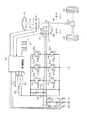
以下、本発明にかかる車載電子制御装置及び操舵制御システムを、内燃機関を動力源とする車両に適用した第1の実施形態について、図面を参照しつつ説明する。
なお、各相の誘起電圧eu,ev,ewは、回転角度θeの関数であり、逆起電圧定数Keを用いて、下記の式にて表記できる。
ev=−Keωsin(θe−120) …(c3)
ew=−Keωsin(θe+120) …(c4)
ここで、図3に示されるように、U相からV相へと通電する場合、電流値Iを用いて以下の式(c5)が成立する。
T={−KeωsinθeI−Keωsin(θe−120)(−I)}/ω
=(√3)KeIsin(θe+30) …(c5)
上記の式(c5)の導出過程に鑑みれば、一般に、特定の1相から別の1相に通電した場合に生成されるトルクTは、回転角度θeに対して正弦波形状に変化するものであり、その変化の周期が一電気角周期であることが容易に推察できる。このため、一般に、特定の1相から別の1相に通電する場合には、電動機20の回転角度θeが所定の回転角度に固定されることとなる。
T=−KeI/2{sinθe−2sin(θe−120)+sin(θe+120)}
=3KeIsin(θe+60) …(c6)
以上から、UW相が短絡する場合には、UV相間の通電処理によって固定される回転角度が、正常時のものとは「30度」ずれることがわかる。同様にして、VW相が短絡する場合についても計算することができ、その結果によれば、これらUV相の短絡時とVW相の短絡時とでは、固定される回転角度が互いに相違する。図4の図は、こうした計算結果をプロットすることで作成されたものである。
T=−KeI{sinθe+sin(θe−120)−2sin(θe+120)}/2
…(c7)
上記の式(c7)から、トルクTを生成するために要求される電流Iは、下記となる。
I=−2T/KeI{sinθe+sin(θe−120)−2sin(θe+120)}
…(c8)
上記の式(c8)において、回転角度θeにかかわらず、トルクTを極力一定とするために要求される電流Iをプロットしたものが、図6に実線にて示したグラフである。ちなみに、図6には、破線にて、上記ステップS20において行う通電処理を対比のために示した。この際の電流Iも、上記と同様にして導出可能である。
以下、第2の実施形態について、先の第1の実施形態との相違点を中心に図面を参照しつつ説明する。
以下、第3の実施形態について、先の第1の実施形態との相違点を中心に図面を参照しつつ説明する。
なお、上記各実施形態は、以下のように変更して実施してもよい。
Claims (9)
- 電動式の操舵装置内に搭載される多相回転機を制御対象とし該多相回転機に接続される電力変換回路を操作する車載電子制御装置において、
前記電力変換回路は、高電位側入力端子及び低電位側入力端子のそれぞれを前記多相回転機の各相のそれぞれに選択的に接続可能なスイッチング素子を備えて構成され、
前記電力変換回路を操作して、前記多相回転機の特定の相と前記高電位側の入力端子とを接続して且つ、前記多相回転機の別の相と前記低電位側の入力端子とを接続することで、前記多相回転機に対する通電処理を行う通電処理手段と、
前記通電処理に伴う前記多相回転機の回転角度の検出値の収束値が、正常時に想定される値となるか否かに基づき、前記多相回転機の前記特定の相または別の相とそれら以外の相とが短絡する異常の有無を検出する異常検出手段とを備えることを特徴とする車載電子制御装置。 - 前記多相回転機の任意の1相及び前記電力変換回路のうちの前記任意の1相に接続される部分を構成する電気経路の断線の有無を検出する断線検出手段を更に備え、
前記通電処理手段は、前記特定の相及び前記別の相を、前記断線検出手段によって断線がある旨検出されていない相に設定することを特徴とする請求項1記載の車載電子制御装置。 - 前記電力変換回路は、高電位側入力端子及び低電位側入力端子のそれぞれを前記多相回転機の各相のそれぞれに選択的に接続可能なスイッチング素子を備えて構成されて且つ、前記多相回転機の所定の1相に接続される電気経路がプルアップ又はプルダウンされてなり、
前記断線検出手段は、前記スイッチング素子が全てオフ状態とされる際の前記多相回転機の各相と前記電力変換回路との接続箇所の電圧に基づき前記断線の検出を行うことを特徴とする請求項2記載の車載電子制御装置。 - 前記断線検出手段により前記任意の1相の断線が検出されている場合、前記多相回転機の残りの相に対する通電によって前記多相回転機の制御量を制御すべく前記電力変換回路を操作する異常時制御手段を更に備え、
前記異常時制御手段は、前記異常検出手段によって短絡異常が検出されている場合と検出されていない場合とで、前記多相回転機の回転角度に応じて定まる前記残りの相に流す電流量を変更することを特徴とする請求項2又は3記載の車載電子制御装置。 - 前記操舵装置は、ユーザによって操舵角の変更が指示される被操作手段の回転軸を入力軸とするとともに前記多相回転機によって回転力が付与される回転軸を出力軸として且つ前記入力軸の回転量に対する前記出力軸の回転量の比を可変とする可変手段を備え、
前記出力軸の回転量に対する前記入力軸の回転量の比が最小となるように前記可変手段を操作した状態で前記通電処理手段による通電処理を行うことを特徴とする請求項1〜4のいずれか1項に記載の車載電子制御装置。 - 前記可変手段は、前記入力軸と前記出力軸とを機械的に連結又は解除する手段を備え、
前記出力軸の回転量に対する前記入力軸の回転量の比が最小となるように前記可変手段を操作した状態は、前記入力軸と前記出力軸との機械的な連結を解除した状態であることを特徴とする請求項5記載の車載電子制御装置。 - 前記操舵装置は、ユーザによって操舵角の変更が指示される被操作手段の回転軸を入力軸とするとともに前記多相回転機によって回転力が付与される回転軸を出力軸として且つ前記入力軸と前記出力軸とが機械的に連結され又は連結可能とされるものであり、
前記被操作手段の操作がなされると判断される場合、前記通電処理手段による通電処理を強制的に停止させる手段を更に備えることを特徴とする請求項1〜6のいずれか1項に記載の車載電子制御装置。 - 前記通電処理手段は、前記多相回転機の駆動要求がない期間において前記通電処理を行うことを特徴とする請求項1〜7のいずれか1項に記載の車載電子制御装置。
- 請求項1〜8のいずれか1項に記載の車載電子制御装置と、
前記操舵装置とを備えることを特徴とする操舵制御システム。
Priority Applications (3)
| Application Number | Priority Date | Filing Date | Title |
|---|---|---|---|
| JP2008152504A JP5115344B2 (ja) | 2008-06-11 | 2008-06-11 | 車載電子制御装置及び操舵制御システム |
| US12/468,305 US8154241B2 (en) | 2008-06-11 | 2009-05-19 | In-vehicle electronic control apparatus and steering control system |
| DE102009023372A DE102009023372A1 (de) | 2008-06-11 | 2009-05-29 | Elektronische Steuereinrichtung für Fahrzeuge und Lenkungssteuersystem |
Applications Claiming Priority (1)
| Application Number | Priority Date | Filing Date | Title |
|---|---|---|---|
| JP2008152504A JP5115344B2 (ja) | 2008-06-11 | 2008-06-11 | 車載電子制御装置及び操舵制御システム |
Publications (2)
| Publication Number | Publication Date |
|---|---|
| JP2009303315A JP2009303315A (ja) | 2009-12-24 |
| JP5115344B2 true JP5115344B2 (ja) | 2013-01-09 |
Family
ID=41317966
Family Applications (1)
| Application Number | Title | Priority Date | Filing Date |
|---|---|---|---|
| JP2008152504A Expired - Fee Related JP5115344B2 (ja) | 2008-06-11 | 2008-06-11 | 車載電子制御装置及び操舵制御システム |
Country Status (3)
| Country | Link |
|---|---|
| US (1) | US8154241B2 (ja) |
| JP (1) | JP5115344B2 (ja) |
| DE (1) | DE102009023372A1 (ja) |
Families Citing this family (21)
| Publication number | Priority date | Publication date | Assignee | Title |
|---|---|---|---|---|
| JP4911231B2 (ja) * | 2010-02-15 | 2012-04-04 | 株式会社デンソー | 回転電機制御装置、および、これを用いた電動パワーステアリング装置 |
| JP5472730B2 (ja) * | 2010-02-26 | 2014-04-16 | 株式会社デンソー | 回転電機制御装置、および、これを用いた電動パワーステアリング装置 |
| JP5168307B2 (ja) * | 2010-04-07 | 2013-03-21 | 株式会社デンソー | 電動機制御装置 |
| DE102011101728A1 (de) | 2010-08-09 | 2012-02-09 | Volkswagen Aktiengesellschaft | Verfahren zum Notlaufbetrieb eines elektromechanischen Lenksysytems und elektronisch kommutierbarer Elektromotor |
| US9119655B2 (en) | 2012-08-03 | 2015-09-01 | Stryker Corporation | Surgical manipulator capable of controlling a surgical instrument in multiple modes |
| US9921712B2 (en) | 2010-12-29 | 2018-03-20 | Mako Surgical Corp. | System and method for providing substantially stable control of a surgical tool |
| JP5641335B2 (ja) * | 2011-01-31 | 2014-12-17 | 株式会社デンソー | 電力変換装置 |
| JP5408193B2 (ja) * | 2011-06-23 | 2014-02-05 | トヨタ自動車株式会社 | 車両の異常検出装置 |
| JP5862135B2 (ja) * | 2011-09-12 | 2016-02-16 | 株式会社ジェイテクト | 電動パワーステアリング装置 |
| US9226796B2 (en) | 2012-08-03 | 2016-01-05 | Stryker Corporation | Method for detecting a disturbance as an energy applicator of a surgical instrument traverses a cutting path |
| US9820818B2 (en) | 2012-08-03 | 2017-11-21 | Stryker Corporation | System and method for controlling a surgical manipulator based on implant parameters |
| KR102304096B1 (ko) | 2012-08-03 | 2021-09-24 | 스트리커 코포레이션 | 로봇 수술을 위한 시스템 및 방법 |
| CN104584423B (zh) * | 2013-08-12 | 2017-06-13 | 日本精工株式会社 | 马达控制装置、使用该马达控制装置的电动助力转向装置以及车辆 |
| JP5835301B2 (ja) * | 2013-10-22 | 2015-12-24 | 株式会社デンソー | 電源電流監視装置 |
| CN103983891B (zh) * | 2014-05-30 | 2018-10-09 | 台达电子企业管理(上海)有限公司 | 逆变器电路的短路故障检测装置及方法 |
| US9714973B2 (en) * | 2014-11-21 | 2017-07-25 | Stmicroelectronics Asia Pacific Pte Ltd | Short circuit detection module |
| JP6550978B2 (ja) * | 2015-07-02 | 2019-07-31 | 株式会社ジェイテクト | 埋込磁石同期電動機の制御装置 |
| WO2018112025A1 (en) | 2016-12-16 | 2018-06-21 | Mako Surgical Corp. | Techniques for modifying tool operation in a surgical robotic system based on comparing actual and commanded states of the tool relative to a surgical site |
| JP7435410B2 (ja) | 2020-11-09 | 2024-02-21 | 株式会社デンソー | モータ制御装置 |
| KR102554627B1 (ko) * | 2021-06-30 | 2023-07-12 | 현대모비스 주식회사 | 조향휠 락킹 제어 장치 및 방법 |
| KR20230138720A (ko) * | 2022-03-24 | 2023-10-05 | 에이치엘만도 주식회사 | 차량 조향 장치 및 이의 구동 방법 |
Family Cites Families (19)
| Publication number | Priority date | Publication date | Assignee | Title |
|---|---|---|---|---|
| JP2718812B2 (ja) * | 1990-08-28 | 1998-02-25 | 株式会社東芝 | センサレス・スピンドルモータ制御回路 |
| JP2704081B2 (ja) * | 1992-03-30 | 1998-01-26 | 株式会社東芝 | センサレス・スピンドルモータ制御回路 |
| JP3388525B2 (ja) | 1994-12-02 | 2003-03-24 | アイシン精機株式会社 | 電気モータの断線検出装置 |
| JPH11187690A (ja) * | 1997-12-18 | 1999-07-09 | Toshiba Corp | インバータ装置及びブラシレスファンモータ |
| JP4178217B2 (ja) * | 2002-03-27 | 2008-11-12 | 株式会社ジェイテクト | 車両用操舵装置 |
| JP4367620B2 (ja) * | 2003-12-22 | 2009-11-18 | 株式会社デンソー | モータ駆動システムの異常診断装置 |
| JP4069886B2 (ja) * | 2004-03-15 | 2008-04-02 | トヨタ自動車株式会社 | 車輌の挙動制御装置 |
| EP1737116B1 (en) * | 2004-03-19 | 2019-09-04 | Mitsubishi Denki Kabushiki Kaisha | Motor controller |
| JP4433856B2 (ja) | 2004-03-31 | 2010-03-17 | 株式会社ジェイテクト | モータ制御装置、車両用操舵装置及び断線検出方法 |
| JP4453429B2 (ja) * | 2004-04-20 | 2010-04-21 | 株式会社ジェイテクト | 油圧式のギア比可変パワーステアリング装置 |
| JP2006050803A (ja) * | 2004-08-05 | 2006-02-16 | Favess Co Ltd | モータ駆動装置 |
| JP4449918B2 (ja) * | 2006-02-15 | 2010-04-14 | トヨタ自動車株式会社 | 電動パワーステアリング装置 |
| JP2007274849A (ja) * | 2006-03-31 | 2007-10-18 | Nsk Ltd | 電動式パワーステアリング装置 |
| KR101040890B1 (ko) * | 2006-04-20 | 2011-06-16 | 미쓰비시덴키 가부시키가이샤 | 전동기 제어 장치 |
| EP1967443A3 (en) * | 2007-03-09 | 2009-03-11 | NSK Ltd. | Electric power steering apparatus, controlling method thereof and program for electric power steering apparatus |
| JP5082719B2 (ja) * | 2007-09-26 | 2012-11-28 | 株式会社ジェイテクト | モータ制御装置及び電動パワーステアリング装置 |
| JP4462351B2 (ja) * | 2008-01-09 | 2010-05-12 | 株式会社デンソー | 回転機の制御装置 |
| JP5370139B2 (ja) * | 2009-12-25 | 2013-12-18 | 株式会社デンソー | 電動パワーステアリング装置 |
| JP5531896B2 (ja) * | 2010-02-04 | 2014-06-25 | 日産自動車株式会社 | 電動油圧装置および電動油圧装置の作動油温度制御方法 |
-
2008
- 2008-06-11 JP JP2008152504A patent/JP5115344B2/ja not_active Expired - Fee Related
-
2009
- 2009-05-19 US US12/468,305 patent/US8154241B2/en not_active Expired - Fee Related
- 2009-05-29 DE DE102009023372A patent/DE102009023372A1/de not_active Withdrawn
Also Published As
| Publication number | Publication date |
|---|---|
| DE102009023372A1 (de) | 2009-12-17 |
| US20090308683A1 (en) | 2009-12-17 |
| US8154241B2 (en) | 2012-04-10 |
| JP2009303315A (ja) | 2009-12-24 |
Similar Documents
| Publication | Publication Date | Title |
|---|---|---|
| JP5115344B2 (ja) | 車載電子制御装置及び操舵制御システム | |
| JP5070867B2 (ja) | モータ制御装置及び電動パワーステアリング装置 | |
| CN102687389B (zh) | 马达驱动系统、马达驱动系统的控制方法、以及行驶装置 | |
| JP3559260B2 (ja) | 電動パワーステアリング制御装置及び制御方法 | |
| JP5262931B2 (ja) | 電動パワーステアリング装置 | |
| JP5338969B2 (ja) | 電源状態診断方法及び装置 | |
| JP2008301658A (ja) | モータ制御装置及び電動パワーステアリング装置 | |
| JP4710528B2 (ja) | 電動パワーステアリング装置 | |
| JP6500653B2 (ja) | インバータの制御装置 | |
| CN103299537A (zh) | 马达控制装置和电动助力转向装置 | |
| JP5018240B2 (ja) | 電動パワーステアリング装置 | |
| JP2008211909A (ja) | モータ制御装置及び電動パワーステアリング装置 | |
| CN108093676A (zh) | 动力转向装置的控制装置及动力转向装置 | |
| EP2567879B1 (en) | Electric power steering system | |
| JP5263079B2 (ja) | 電動パワーステアリング装置 | |
| US12249938B2 (en) | Rotating machine control device | |
| JP2013180661A (ja) | 電子制御装置、異常検出方法 | |
| EP2574523B1 (en) | Vehicle steering system | |
| JP6421710B2 (ja) | インバータの制御装置 | |
| JP4986639B2 (ja) | モータ制御装置 | |
| CN111919379A (zh) | 马达控制装置、电动车辆 | |
| JP2018098974A (ja) | 電動パワーステアリング装置 | |
| JP3881346B2 (ja) | 電動パワーステアリング制御装置 | |
| JP5131435B2 (ja) | 電動パワーステアリング装置 | |
| JP2008118729A (ja) | 電動パワーステアリング装置 |
Legal Events
| Date | Code | Title | Description |
|---|---|---|---|
| A621 | Written request for application examination |
Free format text: JAPANESE INTERMEDIATE CODE: A621 Effective date: 20100702 |
|
| A977 | Report on retrieval |
Free format text: JAPANESE INTERMEDIATE CODE: A971007 Effective date: 20120620 |
|
| A131 | Notification of reasons for refusal |
Free format text: JAPANESE INTERMEDIATE CODE: A131 Effective date: 20120703 |
|
| A521 | Request for written amendment filed |
Free format text: JAPANESE INTERMEDIATE CODE: A523 Effective date: 20120808 |
|
| TRDD | Decision of grant or rejection written | ||
| A01 | Written decision to grant a patent or to grant a registration (utility model) |
Free format text: JAPANESE INTERMEDIATE CODE: A01 Effective date: 20120918 |
|
| A01 | Written decision to grant a patent or to grant a registration (utility model) |
Free format text: JAPANESE INTERMEDIATE CODE: A01 |
|
| A61 | First payment of annual fees (during grant procedure) |
Free format text: JAPANESE INTERMEDIATE CODE: A61 Effective date: 20121001 |
|
| R151 | Written notification of patent or utility model registration |
Ref document number: 5115344 Country of ref document: JP Free format text: JAPANESE INTERMEDIATE CODE: R151 |
|
| FPAY | Renewal fee payment (event date is renewal date of database) |
Free format text: PAYMENT UNTIL: 20151026 Year of fee payment: 3 |
|
| R250 | Receipt of annual fees |
Free format text: JAPANESE INTERMEDIATE CODE: R250 |
|
| R250 | Receipt of annual fees |
Free format text: JAPANESE INTERMEDIATE CODE: R250 |
|
| R250 | Receipt of annual fees |
Free format text: JAPANESE INTERMEDIATE CODE: R250 |
|
| R250 | Receipt of annual fees |
Free format text: JAPANESE INTERMEDIATE CODE: R250 |
|
| LAPS | Cancellation because of no payment of annual fees |