EP2814396B1 - Système et procédé pour naviguer dans une pile de tomosynthèse par utilisation de données d'images synthétisées - Google Patents
Système et procédé pour naviguer dans une pile de tomosynthèse par utilisation de données d'images synthétisées Download PDFInfo
- Publication number
- EP2814396B1 EP2814396B1 EP13749870.5A EP13749870A EP2814396B1 EP 2814396 B1 EP2814396 B1 EP 2814396B1 EP 13749870 A EP13749870 A EP 13749870A EP 2814396 B1 EP2814396 B1 EP 2814396B1
- Authority
- EP
- European Patent Office
- Prior art keywords
- image
- images
- synthesized
- region
- breast
- Prior art date
- Legal status (The legal status is an assumption and is not a legal conclusion. Google has not performed a legal analysis and makes no representation as to the accuracy of the status listed.)
- Active
Links
Images


Classifications
-
- G—PHYSICS
- G06—COMPUTING; CALCULATING OR COUNTING
- G06T—IMAGE DATA PROCESSING OR GENERATION, IN GENERAL
- G06T19/00—Manipulating 3D models or images for computer graphics
- G06T19/003—Navigation within 3D models or images
-
- A—HUMAN NECESSITIES
- A61—MEDICAL OR VETERINARY SCIENCE; HYGIENE
- A61B—DIAGNOSIS; SURGERY; IDENTIFICATION
- A61B6/00—Apparatus for radiation diagnosis, e.g. combined with radiation therapy equipment
- A61B6/02—Devices for diagnosis sequentially in different planes; Stereoscopic radiation diagnosis
- A61B6/025—Tomosynthesis
-
- A—HUMAN NECESSITIES
- A61—MEDICAL OR VETERINARY SCIENCE; HYGIENE
- A61B—DIAGNOSIS; SURGERY; IDENTIFICATION
- A61B6/00—Apparatus for radiation diagnosis, e.g. combined with radiation therapy equipment
- A61B6/46—Apparatus for radiation diagnosis, e.g. combined with radiation therapy equipment with special arrangements for interfacing with the operator or the patient
- A61B6/461—Displaying means of special interest
- A61B6/466—Displaying means of special interest adapted to display 3D data
-
- A—HUMAN NECESSITIES
- A61—MEDICAL OR VETERINARY SCIENCE; HYGIENE
- A61B—DIAGNOSIS; SURGERY; IDENTIFICATION
- A61B6/00—Apparatus for radiation diagnosis, e.g. combined with radiation therapy equipment
- A61B6/50—Clinical applications
- A61B6/502—Clinical applications involving diagnosis of breast, i.e. mammography
-
- G—PHYSICS
- G06—COMPUTING; CALCULATING OR COUNTING
- G06F—ELECTRIC DIGITAL DATA PROCESSING
- G06F3/00—Input arrangements for transferring data to be processed into a form capable of being handled by the computer; Output arrangements for transferring data from processing unit to output unit, e.g. interface arrangements
- G06F3/01—Input arrangements or combined input and output arrangements for interaction between user and computer
- G06F3/048—Interaction techniques based on graphical user interfaces [GUI]
- G06F3/0481—Interaction techniques based on graphical user interfaces [GUI] based on specific properties of the displayed interaction object or a metaphor-based environment, e.g. interaction with desktop elements like windows or icons, or assisted by a cursor's changing behaviour or appearance
- G06F3/04815—Interaction with a metaphor-based environment or interaction object displayed as three-dimensional, e.g. changing the user viewpoint with respect to the environment or object
-
- G—PHYSICS
- G06—COMPUTING; CALCULATING OR COUNTING
- G06F—ELECTRIC DIGITAL DATA PROCESSING
- G06F3/00—Input arrangements for transferring data to be processed into a form capable of being handled by the computer; Output arrangements for transferring data from processing unit to output unit, e.g. interface arrangements
- G06F3/01—Input arrangements or combined input and output arrangements for interaction between user and computer
- G06F3/048—Interaction techniques based on graphical user interfaces [GUI]
- G06F3/0484—Interaction techniques based on graphical user interfaces [GUI] for the control of specific functions or operations, e.g. selecting or manipulating an object, an image or a displayed text element, setting a parameter value or selecting a range
- G06F3/04842—Selection of displayed objects or displayed text elements
-
- G—PHYSICS
- G06—COMPUTING; CALCULATING OR COUNTING
- G06T—IMAGE DATA PROCESSING OR GENERATION, IN GENERAL
- G06T7/00—Image analysis
- G06T7/0002—Inspection of images, e.g. flaw detection
- G06T7/0012—Biomedical image inspection
-
- G—PHYSICS
- G06—COMPUTING; CALCULATING OR COUNTING
- G06T—IMAGE DATA PROCESSING OR GENERATION, IN GENERAL
- G06T2207/00—Indexing scheme for image analysis or image enhancement
- G06T2207/30—Subject of image; Context of image processing
- G06T2207/30004—Biomedical image processing
- G06T2207/30068—Mammography; Breast
Definitions
- the inventions disclosed herein pertain to breast imaging using tomosynthesis, and more specifically to a system and method for guiding the navigation of a tomosynthesis data set, which employs a synthesized 2D image that is obtained by importing relevant data from the tomosynthesis data set into the synthesized image, and then using the 2D image to navigate the tomosynthesis data.
- Mammography has long been used to screen for breast cancer and other abnormalities.
- mammograms have been formed on x-ray film.
- flat panel digital imagers have been introduced that acquire a mammogram in digital form, and thereby facilitate analysis and storage of the acquired images, and provide other benefits as well.
- substantial attention and technological development has been dedicated towards obtaining three-dimensional images of the breast, using methods such as breast tomosynthesis.
- breast tomosynthesis systems construct a 3D image volume from a series of 2D projection images, each projection image obtained at a different angular displacement of an x-ray source relative to the image detector as the x-ray source is scanned over the detector.
- the constructed 3D image volume is typically presented as a plurality of slices of image data, the slices being geometrically reconstructed on planes parallel to the imaging detector.
- the reconstructed tomosynthesis slices reduce or eliminate the problems caused by tissue overlap and structure noise present in single slice, two-dimensional mammography imaging, by permitting a medical professional (e.g., a radiologist) to scroll through the image slices to view underlying structures.
- Hologic, Inc. www.hologic.com
- Hologic, Inc. has developed a fused, multimode mammography/tomosynthesis system that acquires one or both types of mammogram and tomosynthesis images, either while the breast remains immobilized or in different compressions of the breast.
- Other companies have proposed the introduction of systems which are dedicated to tomosynthesis imaging; i.e., which do not include the ability to also acquire a mammogram.
- tomosynthesis acquisition and image display may present an obstacle to acceptance of the tomosynthesis imaging technology, as medical professionals have grown accustomed to screening and analysis of conventional 2D mammogram images.
- mammograms provide good visualization of micro-calcifications, and can offer higher spatial resolution when compared with tomosynthesis images.
- tomosynthesis images provided by dedicated breast tomosynthesis systems have other desirable characteristics, e.g., better isolation and visualization of structures in the breast, such systems do not leverage the existing interpretation expertise of medical professionals.
- U.S. Patent No. 7,760,924 describes a method of generating a synthesized 2D image, which may be displayed along with tomosynthesis projection or reconstructed images, in order to assist in screening and diagnosis.
- US2011/0110576 discloses a method for displaying 2D synthesized breast images wherein reconstructed slice portions determined by computer aided detection (CAD) are slabbed on corresponding location of said 2D image.
- CAD computer aided detection
- a system and method for processing, displaying and navigating breast tissue information includes: (i) obtaining a plurality of 2D and/or 3D images of a patient's breast; (ii) generating a synthesized 2D image of the patient's breast from the obtained 2D and/or 3D images of the plurality; (iii) displaying the synthesized 2D image; (iv) receiving a user command, or otherwise detecting through a user interface, a user selection or other indication of an object or region in the synthesized 2D image; and (v) displaying at least a portion of one or more images from the plurality, including a source image and/or most similar representation of the user selected or indicated object or region.
- the system may be configured for, and the method may include, concurrently displaying a respective source image and/or most similar representation of a tissue structure or region that corresponds to a given location of a user movable input device in the displayed synthesized 2D image.
- the system is preferably configured for, and the method further includes, generating an index map comprising identifying information of selected images of the plurality of 2D and/or 3D images that are source images or that otherwise contain a most similar representation of regions and/or objects displayed in the synthesized 2D image.
- the index map can thereafter be used by the system for to greatly reduce the time needed to navigate through the images, e.g., a tomosynthesis volume stack of the breast image volume.
- the plurality of source images may include one or more of tomosynthesis projection images, reconstructed tomosynthesis slices, mammograms, contrast enhanced mammograms, and synthesized two dimensional images.
- the plurality of 2D and/or 3D images of a patient's breast are acquired or synthesized X,Y coordinate slices at differing z axis locations of the breast, the images having one or more corresponding X,Y coordinate locations.
- generating the synthesized 2D image includes constructing a merged image by importing one or more objects and/or regions from the images of the plurality into the merged image, wherein an image from which an object or region is imported into the merged image comprises a source image for that object or region.
- each image of the plurality of 2D and/or 3D images preferably contains one or more regions defined by their X,Y coordinate locations that are common for all images of the plurality, wherein one of each said common region is imported from the plurality of images into the merged image based upon a comparison of one or more system and/or user defined attributes of the respective common region of each image.
- an identified object or region of interest in a given image has priority for importation into the merged image over any other identified objects or regions of interest having the same or overlapping X,Y coordinate locations in other image slices based upon a predefined priority scheme, e.g., to reflect the relative clinical importance of the various possible tissue structures.
- the preferred attributes may include attributes indicative of regions of interest, such as cancers, or alternatively such as more accurate representation of breast density or breast anatomy, i.e., truthful breast-border/nipple appearance, or presence of a contrast agent in the case of contrast enhanced mammography. In general, any attribute capable to delivering a high/better-quality image can be relevant.
- an object or region may be automatically highlighted in the synthesized 2D image and/or displayed at least portion of the one or more images from the plurality. Additionally and/or alternatively, an object or region in the synthesized 2D image and/or displayed at least portion of the one or more images from the plurality may be highlighted in response to a further received user command or to certain user activity detected through the user interface.
- an object or region may is highlighted by a contour line representing a boundary of the highlighted object or region.
- the object or region is highlighted in a manner indicating that the highlighted object or region is or contains a specified type of tissue structure.
- a system and method for processing, displaying and navigating breast tissue information includes: (i) obtaining a plurality of tomosynthesis images comprising volumetric image data of a patient's breast; (ii) generating a synthesized 2D image of the patient's breast at least in part from the tomosynthesis images; (iii) displaying the synthesized 2D image; (iv) receiving a user command, or otherwise detecting through a user interface, a user selection or other indication of an object or region in the synthesized 2D image; and (v) displaying at least a portion of one or more tomosynthesis images from the plurality, including a source image and/or most similar representation of the user selected or indicated object or region.
- the system is preferably configured for, and the method further includes, generating an index map that includes identifying information of selected tomosynthesis images of the plurality that are source images or that otherwise contain a most similar representation of regions and/or objects in the synthesized 2D image.
- Tp refers to an image that is similarly two-dimensional (2D), but is acquired at a respective tomosynthesis angle between the breast and the origin of the imaging x rays (typically the focal spot of an x-ray tube), and encompasses the image as acquired, as well as the image data after being processed for display and/or storage or other use.
- Tr refers to an image that is reconstructed from tomosynthesis projection images Tp, for example, in the manner described in one or more of U.S. Patent Application Publication No. 2010/0135558 , and U.S. Patent Nos. 7,760,924 , 7,606,801 , and 7,577,282 , the disclosures of which are fully incorporated by reference herein in their entirety, wherein a Tr image represents a slice of the breast as it would appear in a projection x ray image of that slice at any desired angle, not only at an angle used for acquiring Tp or Mp images.
- Ms refers to synthesized 2D images, which simulate mammography images, such as a craniocaudal (CC) or mediolateral oblique (MLO) images, and are constructed using tomosynthesis projection images Tp, tomosynthesis reconstructed images Tr, or a combination thereof. Examples of methods that may be used to generate Ms images are described in the above-incorporated U.S. Patent Application Publication No. 2010/0135558 , and U.S. Patent No. 7,760,924 .
- I MERGE refers to a 2D image constructed by importing into a single image one or more objects and/or regions from any two or more of Mp, Ms, Tp or Tr images of a patient's breast, wherein an image from which an object or region is imported into the merged image comprises a source image for that object or region, and wherein objects or regions are imported into the merged image at X,Y coordinate locations corresponding to the X,Y coordinate locations of the objects or regions in their respective source image
- I MERGE , Tp, Tr, Ms and Mp each encompasses information, in whatever form, that is sufficient to describe the respective image for display, further processing, or storage.
- the respective I MERGE , Mp, Ms. Tp and Tr images are typically provided in digital form prior to being displayed, with each image being defined by information that identifies the properties of each pixel in a two-dimensional array of pixels.
- the pixel values typically relate to respective measured, estimated, or computed responses to x rays of corresponding volumes in the breast, i.e., voxels or columns of tissue.
- the geometry of the tomosynthesis images (Tr and Tp), mammography images (Ms and Mp) and the merged image I MERGE are matched to a common coordinate system, as described in U.S. Patent No. 7,702,142 , the disclosure of which is hereby incorporated by reference in its entirety. Unless otherwise specified, such coordinate system matching is assumed to be implemented with respect to the embodiments described in the ensuing detailed description of this patent specification.
- FIG. 1 illustrates the flow of data in an exemplary image generation and display system, which incorporates the merged image generation and display technology and features of the presently disclosed inventions. It should be understood that, while FIG. 1 illustrates a particular embodiment of a flow diagram with certain processes taking place in a particular serial order or in parallel, various other embodiments of the presently disclosed inventions are not limited to the performance of the image processing steps in any particular order, unless so specified.
- the image generation and display system includes an image acquisition system 1 that acquires tomosynthesis image data for generating Tp images of a patient's breasts, using the respective three dimensional and/or tomosynthesis acquisition methods of any of the currently available systems.
- Mp images may also be generated.
- Some dedicated tomosynthesis systems or combined tomosynthesis/ mammography systems may be adapted to accept and store legacy mammogram images, (indicated by a dashed line and legend Mp legacy in FIG. 1 ) in a a storage device 2, which is preferably a DICOM-compliant Picture Archiving and Communication System (PACS) storage device.
- PPS Picture Archiving and Communication System
- the Tp images are transmitted from either the acquisition system 1, or from the storage device 2, or both, to a computer system configured as a reconstruction engine 3 that reconstructs the Tp images into reconstructed image "slabs" Tr, representing breast slices of selected thickness and at selected orientations, as disclosed in the above-incorporated patents and application publication.
- the imaging and display system 1 further includes a 2D synthesizer that operates substantially in parallel with the reconstruction engine for generating 2D images that simulate mammograms taken at any orientation (e.g., CC or MLO) using a combination of one or more Tp and/or Tr images.
- the synthesized 2D images may be generated dynamically prior to display (as shown in FIG. 1 ) or may be stored in storage system 2 for later use.
- the synthesized 2D images are interchangeably referenced as T2d and Ms.
- the reconstruction engine 3 and 2D synthesizer are preferably connected to a display system 5 via a fast transmission link.
- the originally acquired Mp and/or Tp images may also be forwarded to the display system 5 for concurrent or toggled viewing with the respective Tr and/or Ms images by a medical professional.
- Mode filters 7a, 7b are disposed between image acquisition and image display.
- Each of the filters 7a and 7b may additionally include customized filters for each type of image (i.e., Tp, Mp, Tr) arranged to identify and highlight certain aspects of the respective image types.
- each imaging mode can be tuned or configured in an optimal way for a specific purpose.
- the tuning or configuration may be automatic, based on the type of the image, or may be defined by manual input, for example through a user interface coupled to a display. In the illustrated embodiment of FIG.
- the filters 7a and 7b are selected to highlight particular characteristics of the images that are best displayed in the respective imaging mode, for example, geared towards highlighting masses or calcifications, or for making the merged image (described below) appear to be a particular image type, such as a 3D reconstructed slice, or a 2D mammogram.
- the system 1 includes an image merge processor 6 that merges relevant image data obtained from a set of available source and synthesized images of a patient's breast to provide a merged 2D image I MERGE for display.
- the set of available images used to generate the merged image I MERGE may include filtered and/or unfiltered Ms, Mp, Tr and/or Tp images. While FIG. 1 depicts all these types of images being input into the image merge processor 6, it is also envisioned within the scope of the disclosed inventions that the merged image may be manually configurable. For example, a user interface or preset configuration may be provided and configured to allow a user to select a particular group of two or more images or image types for generating a synthesized 2D image I MERGE for display.
- a medical professional such as a radiologist, may wish to merge two or more reconstructed tomosynthesis slices (or slabs) in order to provide a merged image showing the most readily discerned structures in the collective tomosynthesis image data in a displayed synthesized 2D image, which essentially maps the tomosynthesis slices (or slabs) at a pixel wise granularity.
- the radiologist may combine a 2D mammogram image, whether Mp or Ms, with a 3D projection, or with selected reconstructed images, in order to obtain a customized merged image that highlights both calcifications and various tissue structures in the breast.
- Filters applied to each type of image can further highlight the types of structures or features in the merged image that are generally most prevalent or most readily discerned in the respective source image type.
- one type of filter may be applied to mammography images to highlight calcifications, while a different filter may be applied to tomosynthesis slices to highlight masses, allowing both the highlighted calcifications and highlighted tissue masses to be displayed in the single merged image.
- Filters may also provide the merged image with a desired look and feel; i.e., to make the merged image appear more like a tomosynthesis or mammography image.
- the display system 5 may be part of a standard acquisition workstation (e.g., of acquisition system 1), or of a standard (multi-display) review station that is physically remote from the acquisition system 1.
- a display connected via a communication network may be used, for example, a display of a personal computer or of a so-called tablet, smart phone or other hand-held device.
- the display 5 of the system is preferably able to display I MERGE , Ms, Mp and Tr (and/or Tp) images concurrently, e.g., in separate side-by-side monitors of a review workstation, although the invention may still be implemented with a single display monitor, by toggling between images.
- Tr slices are preferably reconstructed all to the same size for display, which can be the same as the size of an Mp or Ms image of the breast, or they can be initially reconstructed to sizes determined by the fan shape of the x ray beam used in the acquisition, and then later converted to that same size by appropriate interpolation and/or extrapolation. In this manner, images of different types and from different sources can be displayed in desirable size and resolution.
- an image can be displayed in (1) Fit To View Port mode, in which the size of the displayed image size is maximized such that the entire imaged breast tissue is visible, (2) True Size mode, in which a display pixel on the screen corresponds to a pixel of the image, or (3) Right Size mode, in which the size of a displayed image is adjusted so that it matches that of another image being concurrently displayed, or with which the displayed image is, or can be, toggled.
- the merged image I MERGE is automatically resized, accordingly.
- the system 1 which is described as for purposes of illustration and not limitation in this patent specification, is capable of receiving and displaying selectively tomosynthesis projection images Tp, tomosynthesis reconstruction images Tr, a synthesized mammogram image Ms, and/or mammogram (including contrast mammogram) images Mp, or any one or sub combination of these image types.
- the system 1 employs software to convert (i.e., reconstruct) tomosynthesis images Tp into images Tr, software for synthesizing mammogram images Ms, and software for merging a set of images to provide a merged image that displays, for every region of the merged image, the most relevant feature in that region among all images in the source image set.
- an object of interest or feature in a source image may be considered a 'most relevant' feature for inclusion in the merged image based upon the application of one or more CAD algorithms to the collective source images, wherein the CAD algorithms assign numerical values, weights or thresholds, to pixels or regions of the respective source images based upon identified/detected objects and features of interest within the respective region or between features or, in instances when the merged image is generated directly from the synthesized image without CAD assistance, simply the pixel value, weight or other threshold associated with a pixel or region of the image.
- the objects and features of interest may include, for example, spiculated lesions, calcifications, and the like.
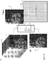
- FIG. 2 is a diagram which pictorially illustrates the merging of image data from a tomosynthesis reconstruction image data set Tr, comprising tomosynthesis slices 10A to 10N, with image data from a mammogram 20, in this case a synthesized mammogram Ms.
- Tr tomosynthesis reconstruction image data set
- Ms synthesized mammogram
- the tomosynthesis image data set Tr and synthesized mammogram Ms are forwarded to the region compare and image merge processor 6, which evaluates each of the source images for which a merged image is to be generated (i.e., whether automatically, or based on a specific user commend) in order to (1) identify the objects and features of interest in each image for those that may be considered a 'most relevant' feature for possible inclusion in the merged image based upon the application of one or more CAD algorithms (as described above), (2) identifies respective pixel regions in the images that contain the identified features, and (3) thereafter compares the images on a region by region basis, searching for that image with the most desirable display data for each respective region.
- the region compare and image merge processor 6 evaluates each of the source images for which a merged image is to be generated (i.e., whether automatically, or based on a specific user commend) in order to (1) identify the objects and features of interest in each image for those that may be considered a 'most relevant' feature for possible inclusion in the merged image
- the image with the most desirable display data may be an image with a highest pixel value, a lowest pixel value, or which has been assigned a threshold value or weight based on the application of a CAD algorithm to the image.
- the pixels of that region are copied over to the corresponding region of the merged image. For example, as shown in FIG. 2 , region 36M from image Ms is written to region 36I. Region 35 of tomosynthesis slice 10A is copied to region 35I of the merged image.
- the regions of FIG. 2 are shown as pre-defined grid regions, it is not necessary that regions be pre-defined in this manner.
- the boundaries of the regions may be dynamically identified during the region compare and image generation process by performing comparisons at pixel or multi-pixel granularities.
- FIG. 3 illustrates a merged image 50, which has been constructed via the combinations of numerous regions of different source images, at arbitrary region boundaries, for example, which may be identified according to the detection of particular features within the respective source images.
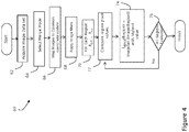
- FIG. 4 is a flow diagram provided to illustrate exemplary steps that may be performed in an image merge process carried out in accordance with one embodiment of the disclosed inventions.
- an image data set is acquired.
- the image data set may be acquired by a tomosynthesis acquisition system, a combination tomosynthesis/mammography system, or by retrieving pre-existing image data from a storage device, whether locally or remotely located relative to an image display device.
- a user may optionally select a merge mode, wherein the user may designate (1) which images are to be used for the source image set to generate the merged image, (2) whether to highlight certain features in the merged image, such as calcifications, spiculated lesions or masses, and (3) whether to display the image as a lower resolution tomosynthesis image, etc.
- the images that are to be merged to generate the merged image are mapped to a common coordinate system, for example, as described in the above-incorporated U.S. Patent No. 7,702,142 . Other methods of matching images of different coordinate systems may alternatively be used.
- the process of comparing regions among the different images begins.
- each I MERGE region is populated with the pixels of the region of an image from the source image set having the most desirable pixels, value, or pattern. The process of populating regions continues until it is determined, at step 76, that all regions have been evaluated, at which point the merged image is ready for display.
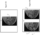
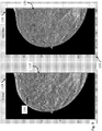
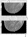
- FIG. 5A and Fig. 5B illustrate two views of a display 80.
- the first view of display 80 shown in FIG. 5A illustrates a merged image 82, having regions sourced by different ones of an acquired or synthesized image set.
- FIG. 5B illustrates a particular feature enabled by the presently disclosed inventions, whereby a user may select a region or area 83 within the merged image 82, and the resulting image source 84 for that area is presented to the user.
- the presently disclosed inventions envision many different mechanisms for selection of the objects of interest and corresponding display of the respective source images corresponding; although it is to be understood that the disclosed inventions are not limited to those described herein.
- the selection of a region or area within the merged image may include a selection of a CAD mark, or alternatively a selection of a particular feature of interest to the reviewer.
- the most relevant slices are made available to the user, the mechanics behind the processes differ.
- One such preferred mechanism is illustrated in FIG. 2 .
- a merge (or "guidance") map 40 is also constructed. The merge map stores, for each region of the merged image, an identifier of the image from which the region is sourced.
- the Ms identifier is stored in region 36, while the 10A TR slice identifier is stored in region 35.
- the merged map may be used during the display of the merged image to permit fast viewing of the respective source image(s) for user-selected regions or objects of interest.
- the CAD overlay may include either CAD marks derived from 3D data, or CAD marks derived from 2D data (if the system has the ability to obtain 2D data).
- CAD marks derived from 3D data generally include, as part of the data object associated with the mark, identifiers of one or more slices which contributed to the generation of the 3D mark.
- selection of the CAD mark results in the retrieval of the series of slices that contributed to the mark.
- the central image slice is displayed; in alternate embodiments, the image slice having the highest weight is displayed; and in a still further alternate embodiment, the image slice having the least visual noise (i.e., the clearest image) is displayed.
- a mechanism for allowing a user to select any object on a merged image, whether it is a CAD mark, or a feature of interest, such as any abnormality or irregularity in the image.
- the user or system may select a region, using for example a mouse click for a single pixel area, or a click and drag action to select a larger region.
- the user may be provided with a selection of graphical frames of various or variable sizes, and have the ability to move the frame to different locations within the merged image to select areas when it is desired to view additional tomosynthesis image slices. In response to such a selection, the particular image slice for initial display may be selected in a variety of ways.
- an image slice could be selected based on the weighting of its associated pixel within the selected region.
- a particular image slice may be selected because a particular feature which is selected, or which is near a pixel or region that is selected, is best viewed in the selected image slice, e.g., provides the clearest view of that region.
- the identification of a particular image slice that is most relevant to a selected pixel or region may utilize pixel information that surrounds the selected object, for example, using region growing techniques known to those in the art.
- pixels that neighbor the selected pixel or region are included in the evaluation for relevant slices if the pixels have a characteristic that satisfies a certain threshold established by the user; for example, including but not limited to the pixels having a particular weight, or being arranged in a particular pattern, etc.
- a group of image slices may be selected, e.g., a successive order of image slices, with a central slice or most heavily weighted slice being first presented.
- the image slice within the group having the least noise i.e., the clearest slice.
- the selection of an image slice for presentation may also take into account a desired visualization mode. Thus, if the user-specified purpose is to visualize calcifications, an image slice having calcification features may be presented ahead of another slice within the group having a lesser calcification characteristic.
- the synthesized 2D merged image can act as a guidance-map, so that the medical professional reviewing the images can focus on the synthesized 2D image for detecting any objects or regions of interest that merit further review, and the system can provide immediate, automated navigation to a "best" corresponding tomosynthesis image slice (or a subset of adjacent tomosynthesis slices) to allow the medical professional to conduct this further review, verify and evaluate the finding.
- the medical professional it is preferred, although not required for practicing all embodiments of the disclosed inventions, for the medical professional to employ a user interface that can display a respective synthesized 2D merged image along-side the tomosynthesis volume image slices, for concurrent viewing of both.
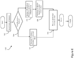
- FIG. 6 illustrates one exemplary process 180 for retrieving and presenting a Tr image slice in response to user-selection of an object of interest in a merged image, which may be implemented using a software program according to one embodiment of the presently disclosed inventions.
- the process 180 operates, in response to a selection of an object of interest in a merged image at step 182.
- the process determines whether the selected object is a CAD mark or a non-CAD mark feature of interest. If it is a CAD mark, at step 185, the Tr slices related to the CAD mark are retrieved.
- one of the Tr slices is selected and presented for display based on at least one of its relative position in the stack, relative weight of the voxel value of the slice, a selected visualization mode, etc. If, at step 184, the process determines that the selected object was a non-CAD mark feature of interest, then at step 186, the source Tr images associated with the selected region are evaluated, and a particular Tr source is selected for display based on its relative voxel value as compared to voxel values in other Tr sources that map to the region. It is noted that the Tr sources that contribute to pixel values within a selected region may be intermittently spaced within the 3D tomosynthesis volume.
- the most relevant Tr source image when selected, it may be presented either alone, or as part of a stack of images together with one or more neighboring Tr slice images.
- the most relevant Tr source may be the presented image, or alternatively another image in the stack associated with the most relevant image may be first presented, for example if that particular image is clearer.
- FIG. 7 depicts another process that may be software-implemented for using a synthesized 2D image for navigating a 3D tomosynthesis image stack ("tomosynthesis stack"), according to another embodiment of the presently disclosed inventions.
- the process includes, at step 92, constructing a tomosynthesis image slice index map, wherein the pixel locations of the synthesized 2D image are mapped to corresponding pixel locations in pertinent image slices of the tomosynthesis stack.
- the tomosynthesis stack index map includes identifying information of selected tomosynthesis slice images from the breast volume stack that are source images or that otherwise contain a most similar representation of regions and/or objects displayed in the synthesized 2D image.
- the tomosynthesis stack index map is preferably generated prior to when a medical professional is ready to conduct his or her review of the breast image data.
- the details for constructing the tomosynthesis stack index map, in accordance with one preferred embodiment, are described below in conjunction with FIG. 8 .
- the synthesized 2D image is displayed to the medical professional (interchangeably referred to as the "user" of the described system), typically on a workstation having side-by-side monitors as depicted in FIGS. 9-11 .
- the medical professional interchangeably referred to as the "user" of the described system
- the workstation having side-by-side monitors as depicted in FIGS. 9-11 .
- only the synthesized 2D image may be presented, e.g., on the left-hand-side monitor, with the right-hand-side monitor being blank, or perhaps depicting a first or middle image slice from the tomosynthesis stack, preferably depending on a user-selectable configuration.
- the system will initially display the synthesized 2D image on the left-hand-side monitor, and a "most relevant" one of the tomosynthesis slice images on the right-hand-side monitor, which was determined by the system based upon the displayed tomosynthesis slice being most similar in appearance to the synthesized 2D image, or having the relatively most interesting objects, out of the tomosynthesis image stack for the entire breast volume.
- the medical professional may use the user-interface to activate the navigational capability of the system.
- the user may affirmatively input a command to select a particular object or region in the displayed synthesized 2D image.
- the system may be configured sot that the user merely positions a "pointer," e.g., a movable cross or arrowhead that is controlled using a mouse or similar input device), overlying an object or region in the displayed synthesized 2D image, thereby "indicating" an interest in the item.
- the system may easily retrieve, at step 96, and display on the right-hand-side monitor, at step 98, the tomosynthesis slice that is either the direct source of the user selected/indicated object or region, or which otherwise contains a most similar representation of the object or region as depicted in the displayed 2D image. Additionally and/or alternatively, the system may be configured for concurrently displaying a respective source image and/or most similar representation of a tissue structure or region that corresponds to a given location of a user movable input device in the displayed synthesized 2D image.
- the plurality of 2D and/or 3D images from which a synthesized 2D image is generated may include tomosynthesis projection images, tomosynthesis reconstruction slices, mammography images, contrast enhanced mammography images, synthesized 2D images, and combinations thereof.
- the synthesized 2D image advantageously incorporates the most relevant information from each of the underlying acquired and computer generated image data sets of the patient's breast.
- different regions of pixels in the displayed synthesized 2D image may be sourced from corresponding different images in the underlying image data set, depending on which underlying image is best for viewing an object of interest, e.g., a mass or a calcification, in the respective region.
- the particular regions may be identified statically, i.e., within a particular grid, or dynamically, i.e., based on identified objects of interest, and may range in granularity from as little as one pixel, to all pixels in the respective image.
- priority is given to first importing into a merged image under construction those regions containing one or more specific tissue structures of interest in the images of a tomosynthesis image data set (or "stack"), and thereafter populating the remaining regions of the merged image with the otherwise most relevant regions from the images, as described above.
- the user interface may additionally include features to enable the medical professional to manipulate the presented tomosynthesis data, for example, to allow the medical professional to scan through adjacent image slices of the tomosynthesis stack, or to further zoom (magnify) into a selected region, to place markers, or alternatively to apply filters or other image processing techniques to the image data.
- the medical professional may quickly review a large stack of tomosynthesis data by utilizing a synthesized 2D image for navigation purposes, thereby increasing the performance and efficiency of breast cancer screening and diagnosis.
- particular types of images may include or be superior for viewing different types of relevant information. For example, calcifications are typically best visualized in 2D mammograms, while masses are typically best visualized using 3D reconstructed images.
- different filters are applied to each of the different types of underlying 2D and/or 3D images in the image data set used to generate the merged image, the filters selected to highlight particular characteristics of the images that are best displayed in the respective imaging mode.
- Appropriate filtering of the images prior to generating the merged image helps ensure that the final merged image includes the most relevant information that can be obtained from all the underlying image types.
- the type of filtering performed for the various images may be defined via user input, which permits a user to select a 'merge mode', for example, geared towards highlighting masses, calcifications, or for making the merged image appear to be a particular image type, such as a 3D reconstructed slice, or a 2D mammogram.
- Synthesizing the 2D image may be accomplished in a variety of ways. For example, in one embodiment, general purpose image filtering algorithms are used to identify features within each of the respective 2D and 3D images, and a user may select whether to use 2D filtered data or 3D filtered data to generate the merged image. Alternatively, 2D or 3D filtered data may be automatically selected in accordance with a particular visualization mode that has been user selected; for example, 2D filtered data may be automatically selected by the system for calcification visualization mode, while 3D filtered data may be automatically selected by the system for mass visualization modes. In one embodiment, two different merged images may be constructed, one for each mode; alternatively, a single merged image may be constructed that takes into account the respective filtered image data results from all available image types.
- features are identified in the available source images and thereafter weighted, e.g., on a pixel by pixel or region by region basis in each respective image.
- a 2D image is then constructed by incorporating the respective regions having the most significant weight in individual images of the available source images.
- the size of the region may vary in granularity from one pixel to many (or even all) pixels of the respective image, and may be statically pre-defined, or may have margins that vary in accordance with the varying thresholds of the source images.
- the synthesized (aka "merged") image may be pre-processed and stored as a DICOM object following tomosynthesis acquisition, and thereafter forwarded with the reconstruction data for subsequent review by a medical professional.
- the stored DICOM object may include the weighting information, allowing the merged image to be dynamically constructed in response to a request for a synthesized 2D image at the medical professional's work station.
- both the weighting information and the synthesized 2D image may be provided in the DICOM object, allowing presentation of a default merged image, while still enabling customization according to the personal workflow of the reviewer.
- the weighting information can be stored with the image itself, and need not be a separate file.
- the visualization of the synthesized 2D images may have some drawbacks. For example, there may be neighboring regions in the merged image which exhibit bright calcifications, but which in fact are sourced from image slices that are distant from one another in the z plane. Therefore, what may appear to be a cluster of micro-calcifications in the 2D image may, in fact, be individual calcifications that are distributed (i.e., along the z-axis) throughout the breast and thus do not actually represent a micro-calcification cluster that requires further review.
- a 'cluster spread indicator' may be provided with the synthesized 2D image, which visually indicates the distribution of calcifications along the z-plane, allowing the medical professional to quickly assess whether a group of calcifications comprise a calcification cluster.
- the system may determine based on the index map information that more than one tomosynthesis image slice should be displayed for a selected/indicated object type or region, for example, a spiculated mass. In such instances, a series of two or more adjacent tomosynthesis slices are displayed, one after the other, at a timing interval that is preferably user selected. As will be additionally described herein, the user may select or indicate more than one object or region in a given synthesized 2D image.
- the system is preferably configured for, and the method further includes, generating an index map comprising identifying information of selected images of the plurality of 2D and/or 3D images that are source images or that otherwise contain a most similar representation of regions and/or objects displayed in the synthesized 2D image.
- the index map can thereafter be used by the system for to greatly reduce the time needed to navigate through the images, e.g., a tomosynthesis volume stack of the breast image volume.
- the image data contained in the synthesized 2D image 104 is mapped to selected tomosynthesis image slices of a 3D volume 106 to construct a "generic" index map 108.
- the pixel locations in the 2D image 104 is mapped to the pixel locations in the respective 3D (tomosynthesis) images 106 based entirely on image similarity, akin to the pieces of a jigsaw puzzle.
- the generic index map 108 is based entirely on best-fit matching of the appearance of the data in the 2D image to the appearance of the data in the respective 3D images, wherein the slice identification and X,Y coordinates of a 3D image having a most similarly appearing pixel region to a corresponding X,Y region in the 2D region is selected. Potential importance of the respective objects and features in the synthesized 2D image is not taken into account for constructing the generic index map 108.
- an object type index map 114 is generated, in which individual object types, designated as 110-1 to 110-n in FIG. 8 , in the synthesized 2D image are prioritized and assigned weighted values to influence the selection of the best corresponding 3D tomosynthesis image slice.
- an individual object type index map, designated as 112-1 to 112-n in FIG. 8 is generated for each object type identified in the synthesized 2D image, e.g., blob density, spiculated masses, micro-calcifications, etc.
- the individual object type index maps 112-1 to 112-n are then combined to construct the full object type index map 114, which is then blended, at step 116, with the generic index map 108 to provide a composite index map 120, wherein the object type image data is prioritized relative to the generic image data.
- the composite index map 120 is then used by the system for navigating the image slices of the 3D volume 106 in response to a selected or indicated location on the 2D image 104. In this manner, different object types having overlapping X,Y coordinates, i.e., due to their location at different z-axis positions in the volumetric breast image, can nevertheless be separately navigated for selective viewing, since separate mapping indexes are provided (See below example with respect to FIGS. 10 and 11 ).
- an object or region may be automatically highlighted in the synthesized 2D image and/or displayed at least portion of the one or more images from the plurality. Additionally and/or alternatively, an object or region in the synthesized 2D image and/or displayed at least portion of the one or more images from the plurality may be highlighted in response to a further received user command or to certain user activity detected through the user interface.
- an object or region may is highlighted by a contour line representing a boundary of the highlighted object or region.
- the object or region is highlighted in a manner indicating that the highlighted object or region is or contains a specified type of tissue structure.
- FIG. 9 depicts an exemplary work station display 122, including a left-hand side monitor 124 ("C-View") displaying a synthesized 2D image 132 of a patient's breast.
- the synthesized 2D image 132 includes a highlighted tissue structure 134, wherein the highlighting is in the form of a contour line that represents a boundary of the tissue structure.
- this highlighting may have been done automatically by the system, e.g., at the time the 2D image 132 is initially displayed, or only in response to a specific user command or indication, e.g., by hovering a pointer over the object 134 in the 2D image 132.
- the work station display 122 also includes a right-hand side monitor 126 displaying the respective tomosynthesis image 136 (which is slice no. 18 of the tomosynthesis volume stack, as indicated in the lower right hand side of the monitor 126), which is the source image or which otherwise provides a most similar view of the highlighted tissue structure 134 as seen in the synthesized image 132.
- a right-hand side monitor 126 displaying the respective tomosynthesis image 136 (which is slice no. 18 of the tomosynthesis volume stack, as indicated in the lower right hand side of the monitor 126), which is the source image or which otherwise provides a most similar view of the highlighted tissue structure 134 as seen in the synthesized image 132.
- the user interface associated with the display 122 allows for a user to select or otherwise indicate a location on the synthesized 2D image 132, e.g., by displaying a pointer, a cross, a circle, or other similar geometrical object, and then input a certain command type (e.g., mouse click) that will be recognized by the system as a request from the user to have the corresponding source or otherwise most similar tomosynthesis slice(s) depicting the region or object underlying the pointer displayed in monitor 126.
- a certain command type e.g., mouse click
- FIG. 10 depicts the work station display 122, wherein a different synthesized 2D breast image 142 is displayed in the left-hand side C-View monitor 124.
- the synthesized 2D image 142 includes a highlighted tissue structure 144, wherein the highlighting is in the form of a geometric shape, in this case a circle, to indicate that the object 144 is a spiculated mass.
- this highlighting may have been done automatically by the system, e.g., at the time the 2D image 142 is initially displayed, or only in response to a specific user command or indication, e.g., by hovering a pointer over the object 144 in the 2D image 142.
- the right-hand side monitor 126 is displaying the respective tomosynthesis image 146 (which is slice no. 33 of the tomosynthesis volume stack, as indicated in the lower right hand side of the monitor 126), which is the source image or which otherwise provides a most similar view of the highlighted tissue structure 144 as seen in the synthesized image 132.
- FIG. 11 depicts the user work station display 122, including the same synthesized 2D breast image 142 as displayed in FIG. 10 , but now highlighting a region 154 containing micro-calcifications, with the right-hand side monitor displaying the tomosynthesis image slice 156 (which is slice no.
- the system may execute an algorithm to automatically compute the best corresponding image (i.e., X,Y and Z) within the tomosynthesis stack for display on the right-hand-side monitor 126.
- a "tomosynthesis slice indicator" may optionally be provided on the left-hand-side monitor 124, which indicates which tomosynthesis slice number (numbers) would be displayed on the right-hand-side monitor 126 based on a current location of a user curser on the 2D image.
- the available features of the user interface may be extended to function, not only based point/location of the merged image, but also based in a similar fashion on a structure/object/region.
- particular objects or region(s) in the merged image may be automatically highlighted when displayed, based on the system recognition of possible interest in the respective objects, or of objects located in the respective region(s).
- this highlighting is in the form of a contour line 108 that represents a boundary of a highlighted tissue structure.
- a contour line may be similarly used to highlight regions of interest in the displayed image, e.g., containing a number of calcification structures.
- the system is configured to allow the user to "draw" a contour line on the merged image as a way of selecting or otherwise indicating an object or region of interest for causing the system to concurrently display one or more underlying source images of the selected or indicated object or region.
- the system employs known image processing techniques to identify different breast tissue structures in the various source images, and highlight them in the merged image, in particular, tissue structures comprising or related to abnormal objects, such as micro-calcification clusters, round-or-lobulated masses, spiculated masses, architectural distortions, etc.; as well as benign tissue structures comprising or related to normal breast tissues, such as linear tissues, cysts, lymph nodes, blood vessels, etc.
- tissue structures comprising or related to abnormal objects, such as micro-calcification clusters, round-or-lobulated masses, spiculated masses, architectural distortions, etc.
- benign tissue structures comprising or related to normal breast tissues, such as linear tissues, cysts, lymph nodes, blood vessels, etc.
- an object or region consisting of or containing a first type of tissue structure may be highlighted in a first manner in the displayed merged image
- an object or region consisting or containing a second type of tissue structure may be highlighted in a second manner different from the first manner in the displayed merged image.
- the user may input a command through the user interface selecting or otherwise identifying a certain type of tissue structure, and, in response to the received command, the system performs one or both of (i) automatically highlighting in the displayed merged image objects comprising the selected type of tissue structure and/or regions containing one or more objects comprising the selected type of tissue structure, and (ii) automatically concurrently displaying the respective source slice (or otherwise the slice with best depiction of) a tissue structure of the selected type in the breast image data, e.g., a most prominent one of the selected tissue structure type based on a comparison, if more than one is detected in the source image stack.
- the system automatically concurrently displays the source (or otherwise best) tomosynthesis image slice including the corresponding micro-calcification in 3D.
- a user can select (through the user interface) a region in the 2D merged image that has the appearance with radiating line patterns (often an indication of spiculated masses), and the system will concurrently display the source (or otherwise best) 3D tomosynthesis slice, or perhaps to a series of consecutive tomosynthesis slices, for viewing the radiating line patterns.
- the user may input a command through the user interface, activating dynamic display functionality, wherein the system automatically highlights those objects and tissue structures that (dynamically) correspond to the location of a user movable input device in the displayed merged image.
- the system may further comprise automatically concurrently displaying a respective source image of a highlighted selected tissue structure that corresponds to a given location of a user movable input device in the displayed merged image, again, on a dynamic basis.
- the system can be activated to provide a "shadow" cursor is displayed on the right-hand-side monitor 126, in a location corresponding to the same (x,y) location as the user's actual curser on the left-hand-side monitor 124, so that moving the curser around in the 2D image moves the shadow curser in the tomosynthesis image at same X,Y coordinates.
- the reverse can also be implemented, i.e., with the active user curser operable in the right-hand monitor 126, and the show curser in the left-hand monitor 124.
- this dynamic display feature allows the system to follow the user's point of interest, e.g.
- mouse cursor location in the 2d merged image, and dynamically display/highlight the most "meaningful" region(s) underneath in real time. For example, the user can move the mouse (without clicking any button) over a blood vessel, and the system will instantly highlight the vessel contour.
- the mapping concepts described herein may be extended to generate a fully mapped 3D volume, with each of the voxels in the mapped volume storing information related to the associated tomosynthesis slices(s) sourcing the particular voxel.
- the volume may be projected onto a fixed coordinate system, regardless of the actual volume of the breast. Projecting the volume to a fixed coordinate system in this manner facilitates processing of the image data, in particular, simplifying the correlation of voxels obtained during different acquisitions.
- one or more 3D maps may be provided, for example, to map from voxels in one slice of a 3D volume acquired via CC to one or more corresponding voxels in another volume, for example acquired via an MLO view.
- Such an arrangement facilitates comparison of slices obtained from different acquisitions that relate to a similar feature of interest within the breast volume, essentially permitting the medical professional to obtain a multi-planar review of a region of interest.
Claims (13)
- Procédé de traitement, d'affichage et de navigation dans des images de tissu mammaire, comprenant:l'obtention d'une pluralité d'images sources en 2D et/ou 3D (Tp, Tr) d'un sein d'un patient ;la génération d'une image en 2D synthétisée (T2d, Ms) du sein du patient à partir de la pluralité obtenue d'images en 2D et/ou 3D (Tp, Tr);l'affichage de l'image en 2D synthétisée (T2d, Ms);la détection par une interface utilisateur d'un emplacement d'un dispositif d'entrée mobile d'utilisateur dans l'image en 2D affichée synthétisée (T2d, Ms); etl'affichage de façon concomitante d'au moins une partie d'une image source respective (Tp, Tr) qui correspond à un emplacement donné d'un dispositif d'entrée mobile d'utilisateur dans l'image en 2D affichée synthétisée (T2d, Ms).
- Procédé selon la revendication 1, dans lequel la pluralité d'images en 2D et/ou 3D d'un sein d'un patient comprend des tranches acquises ou synthétisées de coordonnées X, Y à différents emplacements de l'axe z du sein, les images ayant un ou plusieurs emplacements de coordonnées X, Y correspondants.
- Procédé selon la revendication 1 ou 2, dans lequel la génération de l'image en 2D synthétisée comprend la construction d'une image fusionnée (IFUSION) en important un(e) ou plusieurs objets et/ou régions de deux quelconques, ou plus, des images Mp, Ms, Tp ou Tr du sein du patient dans l'image fusionnée, dans lequel une image à partir de laquelle un objet ou une région est importé(e) dans l'image fusionnée comprend une image source pour cet objet ou cette région,
dans lequel de préférence des objets ou régions sont importé(e)s dans l'image fusionnée sur des emplacements de coordonnées X, Y correspondant aux emplacements de coordonnées X, Y des objets ou régions respectifs dans leur image source,
dans lequel de manière davantage préférée, chaque image de la pluralité des images sources en 2D et/ou 3D contient une ou plusieurs régions définies par leurs emplacements de coordonnées X, Y qui sont communes à toutes les images de la pluralité, et dans lequel l'une de chacune desdites régions communes est importée de deux quelconques, ou plus, d'images Mp, Ms, Tp ou Tr dans l'image fusionnée (IFUSION) sur la base d'une comparaison d'un ou plusieurs attributs de la région commune respective de chaque image, et dans lequel de manière encore davantage préférée, au moins l'un des un ou plusieurs attributs est sélectionné par l'utilisateur. - Procédé selon l'une quelconque des revendications précédentes, comprenant en outre la génération d'une carte-index comprenant l'identification d'informations des images sources sélectionnées de la pluralité des images sources en 2D et/ou 3D (Tr et/ou Tp) qui sont des images sources ou qui contiennent par ailleurs une représentation la plus similaire de régions et/ou objets affiché(e)s dans l'image en 2D synthétisée (T2d, Ms).
- Procédé selon l'une quelconque des revendications précédentes,- dans lequel un objet ou une région est automatiquement mis(e) en évidence dans l'image en 2D synthétisée (T2d, Ms) et/ou dans au moins la partie affichée des une ou plusieurs images sources de la pluralité (Tr et/ou Tp); et/ou- comprenant en outre la mise en évidence d'un objet ou d'une région dans l'image en 2D synthétisée (T2d, Ms) et/ou dans au moins la partie affichée des une ou plusieurs images sources (Tr et/ou Tp) de la pluralité, en réponse à une autre commande utilisateur reçue ou à une certaine activité d'utilisateur détectée par l'interface utilisateur, dans lequel de préférence l'objet ou la région est mis(e) en évidence par une ligne de contour représentant une frontière de l'objet ou région mis(e) en évidence ou dans lequel l'objet ou la région est mis(e) en évidence d'une manière indiquant que l'objet ou la région mis(e) en évidence est ou contient une structure tissulaire de type spécifié.
- Procédé selon l'une quelconque des revendications précédentes, dans lequel l'obtention de la pluralité d'images sources en 2D et/ou 3D comprend uniquement l'obtention d'images sources de tomosynthèse (Tp, Tr) comprenant des données d'image volumétrique d'un sein d'un patient.
- Procédé selon la revendication 6, comprenant en outre la génération d'une carte-index comprenant l'identification d'informations d'images de tomosynthèse de la pluralité sélectionnées, qui sont des images sources ou qui contiennent par ailleurs une représentation la plus similaire des régions et/ou objets dans l'image en 2D synthétisée.
- Système de traitement, d'affichage et de navigation dans des images de tissu mammaire comprenant:un ordinateur de traitement d'image;au moins un moniteur d'affichage d'image (5); etune interface utilisateur couplée fonctionnellement à l'ordinateur de traitement d'image,dans lequel l'ordinateur de traitement d'image est configuré pour générer une image en 2D synthétisée d'un sein d'un patient à partir d'une pluralité d'images source en 2D et/ou en 3D (Tp, Tr) d'un sein, et pour afficher l'image en 2D synthétisée sur l'au moins une image d'un moniteur d'affichage, etdans lequel l'ordinateur de traitement d'image est en outre configuré pour entraîner à afficher, sur un moniteur d'affichage identique ou différent de l'un ou plusieurs moniteurs d'affichage, d'au moins une partie d'une ou plusieurs images sources de la pluralité d'images sources en 2D et 3D (Tp, Tr) d'un objet ou d'une région sélectionné(e) ou indiqué(e) par l'utilisateur dans l'image en 2D synthétisée.
- Système selon la revendication 8,- dans lequel la pluralité d'images sources en 2D et/ou 3D (Tp et/ou Tr) comprend des tranches de coordonnées X, Y acquises ou synthétisées sur différents emplacements de l'axe z du sein du patient, les images sources ayant un ou plusieurs emplacements de coordonnées X, Y correspondants; et/ou- dans lequel l'ordinateur de traitement d'image génère l'image en 2D synthétisée par la construction d'une image fusionnée en important un(e) ou plusieurs objets et/ou régions de deux quelconques, ou plus, des images Mp, Ms, Tp ou Tr dans l'image fusionnée, dans lequel de préférence des objets ou régions sont importé(e)s dans l'image fusionnée à des emplacements de coordonnées X, Y correspondant aux emplacements de coordonnées X, Y des objets ou régions respectifs dans leur image source, dans lequel de préférence, chaque image source de la pluralité d'images sources en 2D et/ou 3D contient une ou plusieurs régions définie(s) par leurs emplacements de coordonnées X, Y qui sont communs pour toutes les images sources de la pluralité, et dans lequel l'une de chacune desdites régions communes est importée de la pluralité d'images dans l'image fusionnée par l'ordinateur de traitement d'image sur la base d'une comparaison d'un ou plusieurs attributs de la région commune respective de chaque image, et dans lequel de manière davantage préférée, au moins l'un des un ou plusieurs attributs est sélectionné par l'utilisateur.
- Système selon la revendication 8 ou 9,
l'ordinateur de traitement d'image étant en outre configuré pour générer une carte-index comprenant l'identification d'informations d'images sélectionnées de la pluralité d'images sources en 2D et/ou 3D qui sont des images sources ou qui contiennent par ailleurs une représentation la plus similaire de régions et/ou objets affiché(e)s dans l'image en 2D synthétisée. - Système selon l'une quelconque des revendications 8 à 10,
l'ordinateur de traitement d'image étant en outre configuré pour mettre en évidence un objet ou une région d'intérêt dans l'image en 2D synthétisée, et/ou
dans lequel l'ordinateur de traitement d'image est configuré pour mettre en évidence des objets ou régions dans l'image en 2D affichée, synthétisée, en réponse à une commande utilisateur reçue ou à une certaine activité d'utilisateur détectée par l'interface utilisateur,
dans lequel de préférence l'ordinateur de traitement d'image est configuré pour mettre en évidence des objets ou régions dans l'image en 2D affichée, synthétisée, avec une ligne de contour représentant une frontière de l'objet ou région mis(e) en évidence ou l'ordinateur de traitement d'image est configuré pour mettre en évidence des objets ou régions dans l'image en 2D affichée, synthétisée, d'une manière indiquant que l'objet ou la région mis(e) en évidence est ou contient une structure tissulaire de type spécifié. - Système selon l'une quelconque des revendications 8 à 11;
dans lequel l'ordinateur de traitement d'image est configuré pour générer une image en 2D synthétisée (T2d, Ms) d'un sein d'un patient uniquement à partir d'une pluralité d'images source de tomosynthèse (Tp, Tr) comprenant des données d'image volumétrique d'un sein d'un patient. - Système selon la revendication 12,
l'ordinateur de traitement d'image étant en outre configuré pour générer une carte-index, la carte-index comprenant l'identification d'informations des images de tomosynthèse de la pluralité sélectionnées, qui sont des images sources ou qui contiennent par ailleurs une représentation la plus similaire de régions et/ou objets dans l'image en 2D synthétisée.
Priority Applications (1)
| Application Number | Priority Date | Filing Date | Title |
|---|---|---|---|
| EP17176956.5A EP3315072B1 (fr) | 2012-02-13 | 2013-02-13 | Système et procédé pour naviguer dans une pile de tomosynthèse par utilisation de données d'images synthétisées |
Applications Claiming Priority (2)
| Application Number | Priority Date | Filing Date | Title |
|---|---|---|---|
| US201261597958P | 2012-02-13 | 2012-02-13 | |
| PCT/US2013/025993 WO2013123091A1 (fr) | 2012-02-13 | 2013-02-13 | Système et procédé pour naviguer dans une pile de tomosynthèse par utilisation de données d'images synthétisées |
Related Child Applications (1)
| Application Number | Title | Priority Date | Filing Date |
|---|---|---|---|
| EP17176956.5A Division EP3315072B1 (fr) | 2012-02-13 | 2013-02-13 | Système et procédé pour naviguer dans une pile de tomosynthèse par utilisation de données d'images synthétisées |
Publications (3)
| Publication Number | Publication Date |
|---|---|
| EP2814396A1 EP2814396A1 (fr) | 2014-12-24 |
| EP2814396A4 EP2814396A4 (fr) | 2015-11-04 |
| EP2814396B1 true EP2814396B1 (fr) | 2017-06-21 |
Family
ID=48984668
Family Applications (2)
| Application Number | Title | Priority Date | Filing Date |
|---|---|---|---|
| EP13749870.5A Active EP2814396B1 (fr) | 2012-02-13 | 2013-02-13 | Système et procédé pour naviguer dans une pile de tomosynthèse par utilisation de données d'images synthétisées |
| EP17176956.5A Active EP3315072B1 (fr) | 2012-02-13 | 2013-02-13 | Système et procédé pour naviguer dans une pile de tomosynthèse par utilisation de données d'images synthétisées |
Family Applications After (1)
| Application Number | Title | Priority Date | Filing Date |
|---|---|---|---|
| EP17176956.5A Active EP3315072B1 (fr) | 2012-02-13 | 2013-02-13 | Système et procédé pour naviguer dans une pile de tomosynthèse par utilisation de données d'images synthétisées |
Country Status (6)
| Country | Link |
|---|---|
| US (5) | US9805507B2 (fr) |
| EP (2) | EP2814396B1 (fr) |
| JP (2) | JP6240097B2 (fr) |
| CN (1) | CN104135935A (fr) |
| ES (1) | ES2641456T3 (fr) |
| WO (1) | WO2013123091A1 (fr) |
Cited By (1)
| Publication number | Priority date | Publication date | Assignee | Title |
|---|---|---|---|---|
| EP4101386A4 (fr) * | 2020-02-04 | 2023-07-12 | FUJIFILM Corporation | Dispositif de réglage d'image, procédé et programme |
Families Citing this family (51)
| Publication number | Priority date | Publication date | Assignee | Title |
|---|---|---|---|---|
| US8571289B2 (en) | 2002-11-27 | 2013-10-29 | Hologic, Inc. | System and method for generating a 2D image from a tomosynthesis data set |
| EP1986548B1 (fr) | 2006-02-15 | 2013-01-02 | Hologic, Inc. | Biopsie mammaire et localisation a l'aiguille a l'aide de systemes de tomosynthese |
| EP2485651B1 (fr) | 2009-10-08 | 2020-12-23 | Hologic, Inc. | Système de ponction-biopsie du sein |
| WO2012071429A1 (fr) | 2010-11-26 | 2012-05-31 | Hologic, Inc. | Interface d'utilisateur pour station de travail de visualisation d'images médicales |
| US9020579B2 (en) | 2011-03-08 | 2015-04-28 | Hologic, Inc. | System and method for dual energy and/or contrast enhanced breast imaging for screening, diagnosis and biopsy |
| EP2782505B1 (fr) | 2011-11-27 | 2020-04-22 | Hologic, Inc. | Système et procédé pour générer une image 2d en utilisant des données d'images de mammographie et/ou de tomosynthèse |
| ES2641456T3 (es) | 2012-02-13 | 2017-11-10 | Hologic, Inc. | Sistema y método para navegar por una pila de tomosíntesis usando datos de imágenes sintetizadas |
| US20130342577A1 (en) * | 2012-06-20 | 2013-12-26 | Carestream Health, Inc. | Image synthesis for diagnostic review |
| JP6360495B2 (ja) | 2013-01-10 | 2018-07-18 | ホロジック, インコーポレイテッドHologic, Inc. | トモシンセシスにおけるデータ伝送ボリュームを低減するための方法 |
| EP2967479B1 (fr) | 2013-03-15 | 2018-01-31 | Hologic Inc. | Biopsie guidée par tomosynthèse dans une position couchée |
| CN106170255A (zh) * | 2013-10-24 | 2016-11-30 | 安德鲁·P·史密斯 | 用于导航x射线引导的乳房活检的系统和方法 |
| JP6262869B2 (ja) * | 2014-02-04 | 2018-01-17 | コーニンクレッカ フィリップス エヌ ヴェKoninklijke Philips N.V. | 乳房パラメータマップの生成 |
| US9613440B2 (en) | 2014-02-12 | 2017-04-04 | General Electric Company | Digital breast Tomosynthesis reconstruction using adaptive voxel grid |
| US20170169609A1 (en) * | 2014-02-19 | 2017-06-15 | Koninklijke Philips N.V. | Motion adaptive visualization in medical 4d imaging |
| US10111631B2 (en) | 2014-02-28 | 2018-10-30 | Hologic, Inc. | System and method for generating and displaying tomosynthesis image slabs |
| US10146424B2 (en) * | 2014-02-28 | 2018-12-04 | Dell Products, Lp | Display of objects on a touch screen and their selection |
| EP3682807A1 (fr) * | 2014-09-16 | 2020-07-22 | Sirona Dental, Inc. | Procédés, systèmes, appareils et programmes informatiques pour le traitement d'images tomographiques |
| JP6126058B2 (ja) * | 2014-09-30 | 2017-05-10 | 富士フイルム株式会社 | 画像表示装置、画像処理装置、放射線画像撮影システム、断層画像表示方法、及び断層画像表示プログラム。 |
| WO2016078958A1 (fr) * | 2014-11-20 | 2016-05-26 | Koninklijke Philips N.V. | Procédé pour la génération de clichés de mammographie synthétiques à partir de données de tomosynthèse |
| WO2016142492A1 (fr) * | 2015-03-10 | 2016-09-15 | Koninklijke Philips N.V. | Extraction de structures correspondantes dans des paires d'images médicales |
| US9792703B2 (en) * | 2015-07-06 | 2017-10-17 | Siemens Healthcare Gmbh | Generating a synthetic two-dimensional mammogram |
| WO2017037147A1 (fr) | 2015-09-01 | 2017-03-09 | Koninklijke Philips N.V. | Appareil permettant d'afficher des données d'image médicale d'une partie du corps |
| US9990713B2 (en) * | 2016-06-09 | 2018-06-05 | Definiens Ag | Detecting and visualizing correlations between measured correlation values and correlation reference values of a pathway |
| JP6827739B2 (ja) * | 2016-08-31 | 2021-02-10 | キヤノン株式会社 | 画像表示装置、画像表示方法及びプログラム |
| CN106407687A (zh) * | 2016-09-22 | 2017-02-15 | 沈阳东软医疗系统有限公司 | 一种dicom图像组合的方法及装置 |
| US10157460B2 (en) | 2016-10-25 | 2018-12-18 | General Electric Company | Interpolated tomosynthesis projection images |
| US10096106B2 (en) | 2016-11-10 | 2018-10-09 | General Electric Company | Combined medical imaging |
| US10463333B2 (en) | 2016-12-13 | 2019-11-05 | General Electric Company | Synthetic images for biopsy control |
| EP3600047A1 (fr) * | 2017-03-30 | 2020-02-05 | Hologic, Inc. | Système et procédé de synthèse et de représentation d'image de caractéristique multiniveau hiérarchique |
| JP7174710B2 (ja) * | 2017-03-30 | 2022-11-17 | ホロジック, インコーポレイテッド | 合成乳房組織画像を生成するための標的オブジェクト増強のためのシステムおよび方法 |
| WO2018183549A1 (fr) * | 2017-03-30 | 2018-10-04 | Hologic, Inc. | Système et procédé de synthèse de données d'image de petite dimension à partir de données d'image de grande dimension à l'aide d'une augmentation de grille d'objet |
| WO2018186758A1 (fr) * | 2017-04-07 | 2018-10-11 | Auckland Uniservices Limited | Système de transmission et de visualisation d'une série d'images |
| EP3641635A4 (fr) | 2017-06-20 | 2021-04-07 | Hologic, Inc. | Procédé et système d'imagerie médicale à auto-apprentissage dynamique |
| US10702217B2 (en) * | 2017-08-24 | 2020-07-07 | General Electric Company | System and method for imaging a patient |
| CN109840898A (zh) * | 2017-11-24 | 2019-06-04 | 通用电气公司 | 一种医学图像的成像显示方法和成像设备 |
| EP3518182B1 (fr) * | 2018-01-26 | 2022-05-18 | Siemens Healthcare GmbH | Tranches inclinées en dbt |
| US11442591B2 (en) * | 2018-04-09 | 2022-09-13 | Lockheed Martin Corporation | System, method, computer readable medium, and viewer-interface for prioritized selection of mutually occluding objects in a virtual environment |
| US11204677B2 (en) * | 2018-10-22 | 2021-12-21 | Acclarent, Inc. | Method for real time update of fly-through camera placement |
| JP7236948B2 (ja) | 2019-07-16 | 2023-03-10 | 富士フイルム株式会社 | 画像処理システム、画像処理方法、及び画像処理プログラム |
| US11883206B2 (en) | 2019-07-29 | 2024-01-30 | Hologic, Inc. | Personalized breast imaging system |
| AU2020353680A1 (en) | 2019-09-27 | 2022-02-17 | Hologic, Inc. | AI system for predicting reading time and reading complexity for reviewing 2D/3D breast images |
| JP2022554190A (ja) * | 2019-10-25 | 2022-12-28 | ディープヘルス, インコーポレイテッド | 三次元画像データを解析するためのシステム及び方法 |
| CN110991050B (zh) * | 2019-12-06 | 2022-10-14 | 万翼科技有限公司 | Cad叠图方法及相关产品 |
| EP4101385A4 (fr) * | 2020-02-04 | 2023-07-19 | FUJIFILM Corporation | Dispositif, procédé et programme de réglage d'image |
| JP7416909B2 (ja) | 2020-03-09 | 2024-01-17 | 富士フイルム株式会社 | 表示制御装置、表示制御方法、及び表示制御プログラム |
| CN115297778A (zh) * | 2020-03-18 | 2022-11-04 | 富士胶片株式会社 | 图像处理装置、方法及程序 |
| US11481038B2 (en) | 2020-03-27 | 2022-10-25 | Hologic, Inc. | Gesture recognition in controlling medical hardware or software |
| CN111430011B (zh) * | 2020-03-31 | 2023-08-29 | 杭州依图医疗技术有限公司 | 细胞染色图像的显示方法、处理方法及存储介质 |
| JPWO2022018943A1 (fr) * | 2020-07-22 | 2022-01-27 | ||
| CN113052166A (zh) * | 2021-02-05 | 2021-06-29 | 杭州依图医疗技术有限公司 | 病理图像的显示方法及装置 |
| WO2023140475A1 (fr) * | 2022-01-21 | 2023-07-27 | 주식회사 루닛 | Appareil et procédé de liaison et de fourniture d'emplacement de lésion entre une image de guidage et une image de tomosynthèse 3d comprenant une pluralité de tranches d'image 3d |
Family Cites Families (406)
| Publication number | Priority date | Publication date | Assignee | Title |
|---|---|---|---|---|
| JP4054402B2 (ja) | 1997-04-25 | 2008-02-27 | 株式会社東芝 | X線断層撮影装置 |
| US3502878A (en) | 1967-09-22 | 1970-03-24 | Us Health Education & Welfare | Automatic x-ray apparatus for limiting the field size of a projected x-ray beam in response to film size and to source-to-film distance |
| US7050611B2 (en) | 2001-05-29 | 2006-05-23 | Mevis Breastcare Gmbh Co. Kg | Method and computer system for screening of medical cases |
| US3863073A (en) | 1973-04-26 | 1975-01-28 | Machlett Lab Inc | Automatic system for precise collimation of radiation |
| US3971950A (en) | 1975-04-14 | 1976-07-27 | Xerox Corporation | Independent compression and positioning device for use in mammography |
| US4160906A (en) | 1977-06-23 | 1979-07-10 | General Electric Company | Anatomically coordinated user dominated programmer for diagnostic x-ray apparatus |
| DE2838901C2 (de) | 1978-09-06 | 1986-11-06 | Siemens AG, 1000 Berlin und 8000 München | Katapultrasterlade |
| FR2512024A1 (fr) | 1981-08-27 | 1983-03-04 | Adir | Ethers tricycliques, leur preparation et les compositions pharmaceutiques les contenant |
| FR2549248B1 (fr) | 1983-06-24 | 1986-01-31 | Thomson Csf | Porte-cassette escamotable pour appareil d'examen radiologique et radiographique |
| DE3339775A1 (de) | 1983-11-03 | 1985-05-15 | Siemens AG, 1000 Berlin und 8000 München | Roentgendiagnostikgeraet mit strahlenfiltern |
| JPS60129034A (ja) | 1983-12-16 | 1985-07-10 | 横河メディカルシステム株式会社 | X線断層撮像装置の操作卓 |
| US4706269A (en) | 1985-03-11 | 1987-11-10 | Reina Leo J | Anti-scatter grid structure |
| US4773087A (en) | 1986-04-14 | 1988-09-20 | University Of Rochester | Quality of shadowgraphic x-ray images |
| USRE33634E (en) | 1986-09-23 | 1991-07-09 | Method and structure for optimizing radiographic quality by controlling X-ray tube voltage, current focal spot size and exposure time | |
| US4821727A (en) | 1986-10-30 | 1989-04-18 | Elscint Ltd. | Mammographic biopsy needle holder system |
| US4819258A (en) | 1986-11-28 | 1989-04-04 | Bennett X-Ray Corp. | Auto-setting of KV in an x-ray machine after selection of technic factors |
| US4907156A (en) | 1987-06-30 | 1990-03-06 | University Of Chicago | Method and system for enhancement and detection of abnormal anatomic regions in a digital image |
| US5051904A (en) | 1988-03-24 | 1991-09-24 | Olganix Corporation | Computerized dynamic tomography system |
| US5740270A (en) | 1988-04-08 | 1998-04-14 | Neuromedical Systems, Inc. | Automated cytological specimen classification system and method |
| DK654488A (da) | 1988-11-23 | 1990-05-24 | Nordisk Roentgen Tech App | Roentgenapparat |
| US5099846A (en) | 1988-12-23 | 1992-03-31 | Hardy Tyrone L | Method and apparatus for video presentation from a variety of scanner imaging sources |
| FR2645006A1 (fr) | 1989-03-29 | 1990-10-05 | Gen Electric Cgr | Mammographe equipe d'un dispositif de vue stereotaxiques integre et procede d'utilisation d'un tel mammographe |
| FR2646340A1 (fr) | 1989-04-28 | 1990-11-02 | Gen Electric Cgr | Porte-cassette adaptable en dimension et en position pour mammographie |
| DE58908415D1 (de) | 1989-07-03 | 1994-10-27 | Siemens Ag | Röntgendiagnostikgerät für Mammographieaufnahmen. |
| US5133020A (en) | 1989-07-21 | 1992-07-21 | Arch Development Corporation | Automated method and system for the detection and classification of abnormal lesions and parenchymal distortions in digital medical images |
| US4969174A (en) | 1989-09-06 | 1990-11-06 | General Electric Company | Scanning mammography system with reduced scatter radiation |
| CA2014918A1 (fr) | 1989-09-06 | 1991-03-06 | James A. Mcfaul | Systeme de mammographie par balyage avec meilleure visualisation de la ligne cutanee |
| US5078142A (en) | 1989-11-21 | 1992-01-07 | Fischer Imaging Corporation | Precision mammographic needle biopsy system |
| US5415169A (en) | 1989-11-21 | 1995-05-16 | Fischer Imaging Corporation | Motorized mammographic biopsy apparatus |
| US5240011A (en) | 1991-11-27 | 1993-08-31 | Fischer Imaging Corporation | Motorized biopsy needle positioner |
| AU645535B2 (en) | 1989-11-27 | 1994-01-20 | Bard International, Inc. | Puncture guide for computer tomography |
| US5199056A (en) | 1989-11-28 | 1993-03-30 | Darrah Carol J | Mammography compression paddle |
| US5481623A (en) | 1990-04-19 | 1996-01-02 | Fuji Photo Film Co., Ltd. | Apparatus for determining an image position on imaging media |
| FR2668359B1 (fr) | 1990-10-24 | 1998-02-20 | Gen Electric Cgr | Mammographe muni d'un porte-aiguille perfectionne. |
| US5409497A (en) | 1991-03-11 | 1995-04-25 | Fischer Imaging Corporation | Orbital aiming device for mammo biopsy |
| US5129911A (en) | 1991-03-11 | 1992-07-14 | Siczek Bernard W | Orbital aiming device |
| US5279309A (en) | 1991-06-13 | 1994-01-18 | International Business Machines Corporation | Signaling device and method for monitoring positions in a surgical operation |
| US5163075A (en) | 1991-08-08 | 1992-11-10 | Eastman Kodak Company | Contrast enhancement of electrographic imaging |
| US5941832A (en) | 1991-09-27 | 1999-08-24 | Tumey; David M. | Method and apparatus for detection of cancerous and precancerous conditions in a breast |
| US5594769A (en) | 1991-11-27 | 1997-01-14 | Thermotrex Corporation | Method and apparatus for obtaining stereotactic mammographic guided needle breast biopsies |
| US5289520A (en) | 1991-11-27 | 1994-02-22 | Lorad Corporation | Stereotactic mammography imaging system with prone position examination table and CCD camera |
| US5343390A (en) | 1992-02-28 | 1994-08-30 | Arch Development Corporation | Method and system for automated selection of regions of interest and detection of septal lines in digital chest radiographs |
| US5359637A (en) | 1992-04-28 | 1994-10-25 | Wake Forest University | Self-calibrated tomosynthetic, radiographic-imaging system, method, and device |
| US5386447A (en) | 1992-09-23 | 1995-01-31 | Fischer Imaging Corporation | Mammographic screening and biopsy apparatus |
| US5596200A (en) | 1992-10-14 | 1997-01-21 | Primex | Low dose mammography system |
| FR2703237B1 (fr) | 1993-03-29 | 1995-05-19 | Ge Medical Syst Sa | Mammographe équipé d'un dispositif de prises en vues stéréotaxiques à détecteur numérique et procédé d'utilisation d'un tel mammographe . |
| US5491627A (en) | 1993-05-13 | 1996-02-13 | Arch Development Corporation | Method and system for the detection of microcalcifications in digital mammograms |
| US5878746A (en) | 1993-08-25 | 1999-03-09 | Lemelson; Jerome H. | Computerized medical diagnostic system |
| US5365562A (en) | 1993-09-20 | 1994-11-15 | Fischer Imaging Corporation | Digital imaging apparatus |
| US6075879A (en) | 1993-09-29 | 2000-06-13 | R2 Technology, Inc. | Method and system for computer-aided lesion detection using information from multiple images |
| US5526394A (en) | 1993-11-26 | 1996-06-11 | Fischer Imaging Corporation | Digital scan mammography apparatus |
| US5452367A (en) | 1993-11-29 | 1995-09-19 | Arch Development Corporation | Automated method and system for the segmentation of medical images |
| CA2113752C (fr) | 1994-01-19 | 1999-03-02 | Stephen Michael Rooks | Systeme d'inspection pour l'imagerie de coupe |
| DE4414689C2 (de) | 1994-04-26 | 1996-08-29 | Siemens Ag | Röntgendiagnostikeinrichtung |
| US5499097A (en) | 1994-09-19 | 1996-03-12 | Neopath, Inc. | Method and apparatus for checking automated optical system performance repeatability |
| WO1996010237A1 (fr) | 1994-09-20 | 1996-04-04 | Neopath, Inc. | Dispositif de controle de l'integrite du traitement dans un systeme d'analyse de specimens biologiques |
| US5557097A (en) | 1994-09-20 | 1996-09-17 | Neopath, Inc. | Cytological system autofocus integrity checking apparatus |
| US5647025A (en) | 1994-09-20 | 1997-07-08 | Neopath, Inc. | Automatic focusing of biomedical specimens apparatus |
| US5553111A (en) | 1994-10-26 | 1996-09-03 | The General Hospital Corporation | Apparatus and method for improved tissue imaging |
| US5712890A (en) * | 1994-11-23 | 1998-01-27 | Thermotrex Corp. | Full breast digital mammography device |
| US5506877A (en) | 1994-11-23 | 1996-04-09 | The General Hospital Corporation | Mammography breast compression device and method |
| US5657362A (en) | 1995-02-24 | 1997-08-12 | Arch Development Corporation | Automated method and system for computerized detection of masses and parenchymal distortions in medical images |
| US5671288A (en) | 1995-05-31 | 1997-09-23 | Neopath, Inc. | Method and apparatus for assessing slide and specimen preparation quality |
| US6216540B1 (en) | 1995-06-06 | 2001-04-17 | Robert S. Nelson | High resolution device and method for imaging concealed objects within an obscuring medium |
| WO1997000649A1 (fr) | 1995-06-20 | 1997-01-09 | Wan Sing Ng | Bras articule pour des procedures medicales |
| US5642433A (en) | 1995-07-31 | 1997-06-24 | Neopath, Inc. | Method and apparatus for image contrast quality evaluation |
| US5642441A (en) | 1995-10-24 | 1997-06-24 | Neopath, Inc. | Separation apparatus and method for measuring focal plane |
| US5818898A (en) | 1995-11-07 | 1998-10-06 | Kabushiki Kaisha Toshiba | X-ray imaging apparatus using X-ray planar detector |
| US5693948A (en) | 1995-11-21 | 1997-12-02 | Loral Fairchild Corporation | Advanced CCD-based x-ray image sensor system |
| US5627869A (en) | 1995-11-22 | 1997-05-06 | Thermotrex Corporation | Mammography apparatus with proportional collimation |
| FI955636A0 (fi) | 1995-11-23 | 1995-11-23 | Planmed Oy | Foerfarande och system foer styrning av funktionerna av en mammografiaanordning |
| EP1300713A3 (fr) | 1995-11-30 | 2004-11-03 | Chromavision Medical Systems, Inc. | Procédé et appareil destinés à réaliser une analyse d'image automatisée sur des échantillons biologiques |
| US5769086A (en) | 1995-12-06 | 1998-06-23 | Biopsys Medical, Inc. | Control system and method for automated biopsy device |
| JPH09198490A (ja) | 1996-01-22 | 1997-07-31 | Hitachi Medical Corp | 3次元離散データ投影装置 |
| JPH09238934A (ja) | 1996-03-11 | 1997-09-16 | Toshiba Medical Eng Co Ltd | 画像表示システム |
| DE19619913C2 (de) | 1996-05-17 | 2001-03-15 | Sirona Dental Systems Gmbh | Röntgendiagnostikgerät für Tomosynthese |
| DE19619915A1 (de) | 1996-05-17 | 1997-11-20 | Siemens Ag | Verfahren zur Erstellung von Tomosyntheseaufnahmen |
| DE19619925C2 (de) | 1996-05-17 | 1999-09-09 | Sirona Dental Systems Gmbh | Röntgendiagnostikgerät für Tomosynthese |
| DE19619924A1 (de) | 1996-05-17 | 1997-11-20 | Siemens Ag | Verfahren zur Erstellung von Tomosyntheseaufnahmen |
| US5835079A (en) | 1996-06-13 | 1998-11-10 | International Business Machines Corporation | Virtual pointing device for touchscreens |
| US6067079A (en) | 1996-06-13 | 2000-05-23 | International Business Machines Corporation | Virtual pointing device for touchscreens |
| US5841124A (en) | 1996-06-19 | 1998-11-24 | Neopath, Inc. | Cytological system autofocus integrity checking apparatus |
| US5872828A (en) | 1996-07-23 | 1999-02-16 | The General Hospital Corporation | Tomosynthesis system for breast imaging |
| JPH1033523A (ja) | 1996-07-24 | 1998-02-10 | Hitachi Medical Corp | X線ct装置 |
| US5776062A (en) | 1996-10-15 | 1998-07-07 | Fischer Imaging Corporation | Enhanced breast imaging/biopsy system employing targeted ultrasound |
| US5986662A (en) | 1996-10-16 | 1999-11-16 | Vital Images, Inc. | Advanced diagnostic viewer employing automated protocol selection for volume-rendered imaging |
| US6293282B1 (en) | 1996-11-05 | 2001-09-25 | Jerome Lemelson | System and method for treating select tissue in living being |
| JP3878259B2 (ja) | 1996-11-13 | 2007-02-07 | 東芝医用システムエンジニアリング株式会社 | 医用画像処理装置 |
| US6137527A (en) | 1996-12-23 | 2000-10-24 | General Electric Company | System and method for prompt-radiology image screening service via satellite |
| US7117098B1 (en) | 1997-02-27 | 2006-10-03 | Cellomics, Inc. | Machine-readable storage medium for analyzing distribution of macromolecules between the cell membrane and the cell cytoplasm |
| US5999639A (en) | 1997-09-04 | 1999-12-07 | Qualia Computing, Inc. | Method and system for automated detection of clustered microcalcifications from digital mammograms |
| US20030135115A1 (en) | 1997-11-24 | 2003-07-17 | Burdette Everette C. | Method and apparatus for spatial registration and mapping of a biopsy needle during a tissue biopsy |
| US6442288B1 (en) | 1997-12-17 | 2002-08-27 | Siemens Aktiengesellschaft | Method for reconstructing a three-dimensional image of an object scanned in the context of a tomosynthesis, and apparatus for tomosynthesis |
| JP3554172B2 (ja) | 1998-01-09 | 2004-08-18 | キヤノン株式会社 | 放射線撮影装置 |
| US6175117B1 (en) | 1998-01-23 | 2001-01-16 | Quanta Vision, Inc. | Tissue analysis apparatus |
| US6289235B1 (en) | 1998-03-05 | 2001-09-11 | Wake Forest University | Method and system for creating three-dimensional images using tomosynthetic computed tomography |
| US6081577A (en) | 1998-07-24 | 2000-06-27 | Wake Forest University | Method and system for creating task-dependent three-dimensional images |
| US6375352B1 (en) | 1999-10-01 | 2002-04-23 | General Electric Company | Apparatus and method for obtaining x-ray tomosynthesis data for mammography |
| US6141398A (en) | 1998-08-25 | 2000-10-31 | General Electric Company | Protocol driven image reconstruction, display, and processing in a multislice imaging system |
| US6101236A (en) | 1998-10-02 | 2000-08-08 | University Of Iowa Research Foundation | Iterative method and apparatus for x-ray computed tomographic fluoroscopy |
| WO2000051484A2 (fr) | 1998-11-25 | 2000-09-08 | Fischer Imaging Corporation | Systeme d'interface utilisateur pour imageur mammographique |
| FR2786388B1 (fr) | 1998-11-27 | 2001-02-16 | Ge Medical Syst Sa | Procede de detection d'un tissu de nature determinee en radiologie numerique et son utilisation pour le reglage des parametres d'exposition |
| US6149301A (en) | 1998-12-30 | 2000-11-21 | General Electric Company | X-ray target centering apparatus for radiographic imaging system |
| JP2000200340A (ja) | 1999-01-06 | 2000-07-18 | Ge Yokogawa Medical Systems Ltd | 画像表示方法、画像表示装置およびct装置 |
| US6424332B1 (en) | 1999-01-29 | 2002-07-23 | Hunter Innovations, Inc. | Image comparison apparatus and method |
| WO2000048286A1 (fr) | 1999-01-29 | 2000-08-17 | American Superconductor Corporation | Systeme de distribution d'electricite a stockage d'energie magnetique dans des supraconducteurs |
| US6233473B1 (en) | 1999-02-16 | 2001-05-15 | Hologic, Inc. | Determining body composition using fan beam dual-energy x-ray absorptiometry |
| US6272207B1 (en) | 1999-02-18 | 2001-08-07 | Creatv Microtech, Inc. | Method and apparatus for obtaining high-resolution digital X-ray and gamma ray images |
| US6256370B1 (en) | 2000-01-24 | 2001-07-03 | General Electric Company | Method and apparatus for performing tomosynthesis |
| US6689142B1 (en) | 1999-04-26 | 2004-02-10 | Scimed Life Systems, Inc. | Apparatus and methods for guiding a needle |
| US6292530B1 (en) | 1999-04-29 | 2001-09-18 | General Electric Company | Method and apparatus for reconstructing image data acquired by a tomosynthesis x-ray imaging system |
| DE19922346C2 (de) | 1999-05-14 | 2003-06-18 | Siemens Ag | Röntgendiagnostikeinrichtung für Tomosynthese oder Schichtung |
| US6243441B1 (en) | 1999-07-13 | 2001-06-05 | Edge Medical Devices | Active matrix detector for X-ray imaging |
| US20020173721A1 (en) | 1999-08-20 | 2002-11-21 | Novasonics, Inc. | User interface for handheld imaging devices |
| US6480565B1 (en) | 1999-11-18 | 2002-11-12 | University Of Rochester | Apparatus and method for cone beam volume computed tomography breast imaging |
| US6987831B2 (en) | 1999-11-18 | 2006-01-17 | University Of Rochester | Apparatus and method for cone beam volume computed tomography breast imaging |
| US6245028B1 (en) | 1999-11-24 | 2001-06-12 | Marconi Medical Systems, Inc. | Needle biopsy system |
| US6633674B1 (en) | 1999-11-24 | 2003-10-14 | General Electric Company | Picture archiving and communication system employing improved data compression |
| US6645520B2 (en) | 1999-12-16 | 2003-11-11 | Dermatrends, Inc. | Transdermal administration of nonsteroidal anti-inflammatory drugs using hydroxide-releasing agents as permeation enhancers |
| FR2803069B1 (fr) | 1999-12-28 | 2002-12-13 | Ge Medical Syst Sa | Procede et systeme de compensation de l'epaisseur d'un organe |
| US6411836B1 (en) | 1999-12-30 | 2002-06-25 | General Electric Company | Method and apparatus for user preferences configuring in an image handling system |
| US8352289B2 (en) | 1999-12-30 | 2013-01-08 | Dhi Computing, Inc. | Systems and methods for providing and maintaining electronic medical records |
| US6901156B2 (en) | 2000-02-04 | 2005-05-31 | Arch Development Corporation | Method, system and computer readable medium for an intelligent search workstation for computer assisted interpretation of medical images |
| US6744848B2 (en) | 2000-02-11 | 2004-06-01 | Brandeis University | Method and system for low-dose three-dimensional imaging of a scene |
| GB0006598D0 (en) | 2000-03-17 | 2000-05-10 | Isis Innovation | Three-dimensional reconstructions from images |
| US6351660B1 (en) | 2000-04-18 | 2002-02-26 | Litton Systems, Inc. | Enhanced visualization of in-vivo breast biopsy location for medical documentation |
| US6327336B1 (en) | 2000-06-05 | 2001-12-04 | Direct Radiography Corp. | Radiogram showing location of automatic exposure control sensor |
| US6683934B1 (en) | 2000-06-05 | 2004-01-27 | General Electric Company | Dual energy x-ray imaging system and method for radiography and mammography |
| US6389104B1 (en) | 2000-06-30 | 2002-05-14 | Siemens Corporate Research, Inc. | Fluoroscopy based 3-D neural navigation based on 3-D angiography reconstruction data |
| JP2002052018A (ja) | 2000-08-11 | 2002-02-19 | Canon Inc | 画像表示装置、画像表示方法および記憶媒体 |
| JP2002109510A (ja) | 2000-09-27 | 2002-04-12 | Fuji Photo Film Co Ltd | 異常陰影候補検出処理システム |
| EP1267722A1 (fr) | 2000-10-20 | 2003-01-02 | Koninklijke Philips Electronics N.V. | Tomosynthese dans une portee angulaire limitee |
| US6758824B1 (en) | 2000-11-06 | 2004-07-06 | Suros Surgical Systems, Inc. | Biopsy apparatus |
| WO2002069808A2 (fr) | 2000-11-06 | 2002-09-12 | Suros Surgical Systems, Inc. | Appareil de biopsie |
| US6468226B1 (en) | 2000-11-22 | 2002-10-22 | Mcintyre, Iv John J. | Remote tissue biopsy apparatus and associated methods |
| US7556602B2 (en) | 2000-11-24 | 2009-07-07 | U-Systems, Inc. | Breast cancer screening with adjunctive ultrasound mammography |
| US7103205B2 (en) | 2000-11-24 | 2006-09-05 | U-Systems, Inc. | Breast cancer screening with ultrasound image overlays |
| US7597663B2 (en) | 2000-11-24 | 2009-10-06 | U-Systems, Inc. | Adjunctive ultrasound processing and display for breast cancer screening |
| US7615008B2 (en) | 2000-11-24 | 2009-11-10 | U-Systems, Inc. | Processing and displaying breast ultrasound information |
| US6650928B1 (en) | 2000-11-27 | 2003-11-18 | Ge Medical Systems Global Technology Company, Llc | Color parametric and composite maps for CT perfusion |
| US6501819B2 (en) | 2000-12-18 | 2002-12-31 | Ge Medical Systems Global Technology Company, Llc | Medical diagnostic method and apparatus to control dual energy exposure techniques based on image information |
| FR2818116B1 (fr) | 2000-12-19 | 2004-08-27 | Ge Med Sys Global Tech Co Llc | Appareil de mammographie |
| JP2004517408A (ja) | 2000-12-22 | 2004-06-10 | コーニンクレッカ フィリップス エレクトロニクス エヌ ヴィ | クリッピング面間の領域の立体的ビューイング |
| US6463181B2 (en) | 2000-12-22 | 2002-10-08 | The United States Of America As Represented By The Secretary Of The Navy | Method for optimizing visual display of enhanced digital images |
| EP1364374A4 (fr) | 2001-02-01 | 2006-11-22 | Creatv Microtech Inc | Modeles de collimateurs et de grilles antidiffusion, et leur deplacement, fabrication et assemblage |
| US7030861B1 (en) | 2001-02-10 | 2006-04-18 | Wayne Carl Westerman | System and method for packing multi-touch gestures onto a hand |
| US6486764B2 (en) | 2001-02-16 | 2002-11-26 | Delphi Technologies, Inc. | Rotary position sensor |
| US20020188466A1 (en) | 2001-04-18 | 2002-12-12 | Barrette Pierre Philip | Secure digital medical intellectual property (IP) distribution, market applications, and mobile devices |
| US6620111B2 (en) | 2001-04-20 | 2003-09-16 | Ethicon Endo-Surgery, Inc. | Surgical biopsy device having automatic rotation of the probe for taking multiple samples |
| US6954667B2 (en) | 2001-06-28 | 2005-10-11 | Chemimage Corporation | Method for Raman chemical imaging and characterization of calcification in tissue |
| US6611575B1 (en) | 2001-07-27 | 2003-08-26 | General Electric Company | Method and system for high resolution 3D visualization of mammography images |
| WO2003017244A1 (fr) | 2001-08-17 | 2003-02-27 | Multidigit, Inc. | Systeme et procede de selection d'actions sur la base de l'identification des doigts d'un utilisateur |
| AU2002332758A1 (en) | 2001-08-31 | 2003-03-18 | Analogic Corporation | Image positioning method and system for tomosynthesis in a digital x-ray radiography system |
| US20030072478A1 (en) | 2001-10-12 | 2003-04-17 | Claus Bernhard Erich Hermann | Reconstruction method for tomosynthesis |
| JP4363833B2 (ja) * | 2001-10-16 | 2009-11-11 | 株式会社東芝 | 局所血流動態に関するインデックスを演算する方法及び装置 |
| WO2003037046A2 (fr) | 2001-10-19 | 2003-05-01 | Hologic, Inc. | Systeme et procede de mammographie utilisant des palpateurs de compression excentres, la collimation automatique et une grille anti-diffusion retractable |
| US6626849B2 (en) | 2001-11-01 | 2003-09-30 | Ethicon Endo-Surgery, Inc. | MRI compatible surgical biopsy device |
| EP1313066B1 (fr) | 2001-11-19 | 2008-08-27 | STMicroelectronics S.r.l. | Procédé de fusion d'images numérisées pour l'obtention d'une image numérisée à plage dynamique étendue |
| US6895077B2 (en) | 2001-11-21 | 2005-05-17 | University Of Massachusetts Medical Center | System and method for x-ray fluoroscopic imaging |
| US6751285B2 (en) | 2001-11-21 | 2004-06-15 | General Electric Company | Dose management system for mammographic tomosynthesis |
| US20030097055A1 (en) | 2001-11-21 | 2003-05-22 | Philips Medical Systems(Cleveland), Inc. | Method of reviewing tomographic scans with a large number of images |
| JP4099984B2 (ja) | 2001-12-14 | 2008-06-11 | コニカミノルタホールディングス株式会社 | 異常陰影検出装置および画像出力装置 |
| US6978040B2 (en) | 2001-12-19 | 2005-12-20 | Canon Kabushiki Kaisha | Optical recovery of radiographic geometry |
| US6647092B2 (en) | 2002-01-18 | 2003-11-11 | General Electric Company | Radiation imaging system and method of collimation |
| SE524458C2 (sv) | 2002-03-01 | 2004-08-10 | Mamea Imaging Ab | Skyddsanordning vid en röntgenapparat |
| US7346381B2 (en) | 2002-11-01 | 2008-03-18 | Ge Medical Systems Global Technology Company Llc | Method and apparatus for medical intervention procedure planning |
| US6878115B2 (en) | 2002-03-28 | 2005-04-12 | Ultrasound Detection Systems, Llc | Three-dimensional ultrasound computed tomography imaging system |
| US6882700B2 (en) | 2002-04-15 | 2005-04-19 | General Electric Company | Tomosynthesis X-ray mammogram system and method with automatic drive system |
| US7218766B2 (en) | 2002-04-15 | 2007-05-15 | General Electric Company | Computer aided detection (CAD) for 3D digital mammography |
| US20030194050A1 (en) | 2002-04-15 | 2003-10-16 | General Electric Company | Multi modality X-ray and nuclear medicine mammography imaging system and method |
| US6752767B2 (en) | 2002-04-16 | 2004-06-22 | Vivant Medical, Inc. | Localization element with energized tip |
| US7139000B2 (en) | 2002-05-13 | 2006-11-21 | Ge Medical Systems Global Technology Company, Llc | Method, system and computer product for displaying axial images |
| US7295691B2 (en) | 2002-05-15 | 2007-11-13 | Ge Medical Systems Global Technology Company, Llc | Computer aided diagnosis of an image set |
| US11275405B2 (en) | 2005-03-04 | 2022-03-15 | Apple Inc. | Multi-functional hand-held device |
| US7599579B2 (en) | 2002-07-11 | 2009-10-06 | Ge Medical Systems Global Technology Company, Llc | Interpolated image filtering method and apparatus |
| US7450747B2 (en) | 2002-07-12 | 2008-11-11 | Ge Medical Systems Global Technology Company, Llc | System and method for efficiently customizing an imaging system |
| US20040036680A1 (en) | 2002-08-26 | 2004-02-26 | Mark Davis | User-interface features for computers with contact-sensitive displays |
| US6898331B2 (en) | 2002-08-28 | 2005-05-24 | Bae Systems Aircraft Controls, Inc. | Image fusion system and method |
| US6574304B1 (en) | 2002-09-13 | 2003-06-03 | Ge Medical Systems Global Technology Company, Llc | Computer aided acquisition of medical images |
| US6748044B2 (en) | 2002-09-13 | 2004-06-08 | Ge Medical Systems Global Technology Company, Llc | Computer assisted analysis of tomographic mammography data |
| US7260249B2 (en) * | 2002-09-27 | 2007-08-21 | Confirma Incorporated | Rules-based approach for processing medical images |
| US7347829B2 (en) | 2002-10-07 | 2008-03-25 | Suros Surgical Systems, Inc. | Introduction system for minimally invasive surgical instruments |
| US6940943B2 (en) | 2002-10-07 | 2005-09-06 | General Electric Company | Continuous scan tomosynthesis system and method |
| US6825838B2 (en) * | 2002-10-11 | 2004-11-30 | Sonocine, Inc. | 3D modeling system |
| US20040171933A1 (en) | 2002-11-25 | 2004-09-02 | Milton Stoller | Mammography needle biopsy system and method |
| US7760924B2 (en) | 2002-11-27 | 2010-07-20 | Hologic, Inc. | System and method for generating a 2D image from a tomosynthesis data set |
| US7616801B2 (en) | 2002-11-27 | 2009-11-10 | Hologic, Inc. | Image handling and display in x-ray mammography and tomosynthesis |
| WO2006058160A2 (fr) | 2004-11-26 | 2006-06-01 | Hologic, Inc. | Systeme et procede radiographiques multimode integrant mammographie/tomosynthese |
| US7123684B2 (en) | 2002-11-27 | 2006-10-17 | Hologic, Inc. | Full field mammography with tissue exposure control, tomosynthesis, and dynamic field of view processing |
| US7577282B2 (en) | 2002-11-27 | 2009-08-18 | Hologic, Inc. | Image handling and display in X-ray mammography and tomosynthesis |
| US6597762B1 (en) | 2002-11-27 | 2003-07-22 | Ge Medical Systems Global Technology Co., Llc | Method and apparatus of lesion detection and validation based on multiple reviews of a CT image |
| US7831296B2 (en) | 2002-11-27 | 2010-11-09 | Hologic, Inc. | X-ray mammography with tomosynthesis |
| US8571289B2 (en) | 2002-11-27 | 2013-10-29 | Hologic, Inc. | System and method for generating a 2D image from a tomosynthesis data set |
| US7406150B2 (en) | 2002-11-29 | 2008-07-29 | Hologic, Inc. | Distributed architecture for mammographic image acquisition and processing |
| US7904824B2 (en) | 2002-12-10 | 2011-03-08 | Siemens Medical Solutions Usa, Inc. | Medical imaging programmable custom user interface system and method |
| US7110490B2 (en) | 2002-12-10 | 2006-09-19 | General Electric Company | Full field digital tomosynthesis method and apparatus |
| EP1430835B1 (fr) | 2002-12-17 | 2011-11-16 | Kabushiki Kaisha Toshiba | Système destinés à l'angiographie périphérique par rayons X |
| US7356113B2 (en) | 2003-02-12 | 2008-04-08 | Brandeis University | Tomosynthesis imaging system and method |
| US7333644B2 (en) | 2003-03-11 | 2008-02-19 | Siemens Medical Solutions Usa, Inc. | Systems and methods for providing automatic 3D lesion segmentation and measurements |
| JP4497837B2 (ja) | 2003-05-12 | 2010-07-07 | キヤノン株式会社 | 放射線画像撮影装置 |
| AU2004251359B2 (en) | 2003-06-25 | 2009-01-22 | Siemens Medical Solutions Usa, Inc. | Systems and methods for automated diagnosis and decision support for breast imaging |
| US6885724B2 (en) | 2003-08-22 | 2005-04-26 | Ge Medical Systems Global Technology Company, Llc | Radiographic tomosynthesis image acquisition utilizing asymmetric geometry |
| WO2005023086A2 (fr) | 2003-08-25 | 2005-03-17 | University Of North Carolina At Chapel Hill | Systemes, procedes et produits de programme informatique conçus pour analyser des attributs de vaisseaux aux fins de diagnostic, de stadification de maladie, et de planification chirurgicale |
| US7424141B2 (en) | 2003-08-29 | 2008-09-09 | Agilent Technologies, Inc. | System and method for performing auto-focused tomosynthesis |
| US7578781B2 (en) | 2003-09-18 | 2009-08-25 | Wisconsin Alumni Research Foundation | Device for placement of needles and radioactive seeds in radiotherapy |
| JP2005110843A (ja) * | 2003-10-06 | 2005-04-28 | Canon Inc | 放射線画像処理装置及び処理方法 |
| US7869862B2 (en) | 2003-10-15 | 2011-01-11 | Varian Medical Systems, Inc. | Systems and methods for functional imaging using contrast-enhanced multiple-energy computed tomography |
| US20050089205A1 (en) | 2003-10-23 | 2005-04-28 | Ajay Kapur | Systems and methods for viewing an abnormality in different kinds of images |
| JP2005149107A (ja) | 2003-11-14 | 2005-06-09 | Konica Minolta Medical & Graphic Inc | 医用画像管理システム |
| DE10353611B4 (de) | 2003-11-17 | 2013-01-17 | Siemens Aktiengesellschaft | Röntgendiagnostikgerät für Mammographieuntersuchungen |
| US8265728B2 (en) | 2003-11-26 | 2012-09-11 | University Of Chicago | Automated method and system for the evaluation of disease and registration accuracy in the subtraction of temporally sequential medical images |
| US8712798B2 (en) | 2003-11-26 | 2014-04-29 | Koninklijke Philips N.V. | Workflow optimization for high throughput imaging environments |
| US8768026B2 (en) | 2003-11-26 | 2014-07-01 | Hologic, Inc. | X-ray imaging with x-ray markers that provide adjunct information but preserve image quality |
| US7727151B2 (en) | 2003-11-28 | 2010-06-01 | U-Systems Inc. | Navigation among multiple breast ultrasound volumes |
| US7773721B2 (en) | 2003-12-03 | 2010-08-10 | The General Hospital Corporation | Multi-segment cone-beam reconstruction system and method for tomosynthesis imaging |
| US20050135555A1 (en) | 2003-12-23 | 2005-06-23 | Claus Bernhard Erich H. | Method and system for simultaneously viewing rendered volumes |
| US7653229B2 (en) | 2003-12-23 | 2010-01-26 | General Electric Company | Methods and apparatus for reconstruction of volume data from projection data |
| WO2005072636A1 (fr) | 2004-01-23 | 2005-08-11 | Traxyz Medical, Inc. | Procedes et appareil permettant de realiser des interventions sur des emplacements cibles dans le corps |
| WO2005079306A2 (fr) | 2004-02-13 | 2005-09-01 | University Of Chicago | Procede, systeme, et produit logiciel informatiques destines a etablir une correlation a base de caracteristique de lesions a partir de multiple images |
| US7289825B2 (en) | 2004-03-15 | 2007-10-30 | General Electric Company | Method and system for utilizing wireless voice technology within a radiology workflow |
| US7142633B2 (en) | 2004-03-31 | 2006-11-28 | General Electric Company | Enhanced X-ray imaging system and method |
| US7699783B2 (en) | 2004-04-08 | 2010-04-20 | Techniscan, Inc. | Method for imaging and treating a breast |
| CN1953708B (zh) | 2004-05-14 | 2010-06-16 | 皇家飞利浦电子股份有限公司 | 用于诊断乳腺癌的系统和方法 |
| GB0411402D0 (en) | 2004-05-21 | 2004-06-23 | Tissuomics Ltd | Penetrating radiation measurements |
| US7835562B2 (en) | 2004-07-23 | 2010-11-16 | General Electric Company | Methods and apparatus for noise reduction filtering of images |
| WO2006012568A2 (fr) | 2004-07-23 | 2006-02-02 | Learning Tree International | Systeme et procede de presentations electroniques |
| FR2873835A1 (fr) | 2004-07-29 | 2006-02-03 | Gen Electric | Procede et dispositif d'imagerie aux rayons x avec produit de contraste permettant une visualisation amelioree |
| US7323692B2 (en) | 2004-08-10 | 2008-01-29 | Research Foundation Of State University Of New York | Flat-panel detector with avalanche gain |
| US7725153B2 (en) | 2004-10-04 | 2010-05-25 | Hologic, Inc. | Estimating visceral fat by dual-energy x-ray absorptiometry |
| WO2006055830A2 (fr) | 2004-11-15 | 2006-05-26 | Hologic, Inc. | Generation et affichage geometriques de mise en correspondance de cliches mammaires et d'images de tomosynthese |
| US20060132508A1 (en) | 2004-12-16 | 2006-06-22 | Navid Sadikali | Multi-planar image viewing system and method |
| US7616793B2 (en) | 2004-12-30 | 2009-11-10 | Hologic, Inc. | Medical image review workstation with integrated content-based resource retrieval |
| US9760214B2 (en) | 2005-02-23 | 2017-09-12 | Zienon, Llc | Method and apparatus for data entry input |
| US7859549B2 (en) | 2005-03-08 | 2010-12-28 | Agfa Inc. | Comparative image review system and method |
| US20060210131A1 (en) | 2005-03-15 | 2006-09-21 | Wheeler Frederick W Jr | Tomographic computer aided diagnosis (CAD) with multiple reconstructions |
| JP5038643B2 (ja) | 2005-04-06 | 2012-10-03 | 株式会社東芝 | 画像表示装置 |
| US8373652B2 (en) | 2005-04-06 | 2013-02-12 | Kabushiki Kaisha Toshiba | Image display apparatus and image display method |
| US10492749B2 (en) | 2005-05-03 | 2019-12-03 | The Regents Of The University Of California | Biopsy systems for breast computed tomography |
| DE102005022543A1 (de) | 2005-05-17 | 2006-11-23 | Siemens Ag | Mammographieverfahren und Mammographiegerät |
| US7606801B2 (en) | 2005-06-07 | 2009-10-20 | Varonis Inc. | Automatic management of storage access control |
| US7809175B2 (en) | 2005-07-01 | 2010-10-05 | Hologic, Inc. | Displaying and navigating computer-aided detection results on a review workstation |
| US7245694B2 (en) | 2005-08-15 | 2007-07-17 | Hologic, Inc. | X-ray mammography/tomosynthesis of patient's breast |
| WO2007027610A2 (fr) | 2005-08-30 | 2007-03-08 | Bruce Reiner | Dispositif et procede de navigation multifonctionnel |
| DE202005013910U1 (de) | 2005-09-02 | 2005-11-24 | Siemens Ag | Mammographiegerät mit Gesichtsschild |
| US20070052700A1 (en) | 2005-09-07 | 2007-03-08 | Wheeler Frederick W | System and method for 3D CAD using projection images |
| US10008184B2 (en) | 2005-11-10 | 2018-06-26 | Hologic, Inc. | System and method for generating a 2D image using mammography and/or tomosynthesis image data |
| US7342233B2 (en) | 2005-11-18 | 2008-03-11 | Sectra Mamea Ab | Method and arrangement relating to x-ray imaging |
| US20070118400A1 (en) | 2005-11-22 | 2007-05-24 | General Electric Company | Method and system for gesture recognition to drive healthcare applications |
| US20070236490A1 (en) | 2005-11-25 | 2007-10-11 | Agfa-Gevaert | Medical image display and review system |
| JP2009522005A (ja) | 2005-12-29 | 2009-06-11 | ケアストリーム ヘルス インク | 時間横断的かつモダリティ横断的な医療診断 |
| US20070156451A1 (en) | 2006-01-05 | 2007-07-05 | Gering David T | System and method for portable display of relevant healthcare information |
| US7581399B2 (en) | 2006-01-05 | 2009-09-01 | United Technologies Corporation | Damped coil pin for attachment hanger hinge |
| EP1986548B1 (fr) | 2006-02-15 | 2013-01-02 | Hologic, Inc. | Biopsie mammaire et localisation a l'aiguille a l'aide de systemes de tomosynthese |
| US20070223651A1 (en) | 2006-03-21 | 2007-09-27 | Wagenaar Douglas J | Dual modality mammography device |
| US7489761B2 (en) | 2006-03-27 | 2009-02-10 | Hologic, Inc. | Breast compression for digital mammography, tomosynthesis and other modalities |
| EP2046223B1 (fr) | 2006-04-12 | 2011-03-02 | NAVAB, Nassir | Dispositif de miroir transfixiant virtuel et procédé permettant de visualiser des objets virtuels dans des applications angiographiques |
| US7945083B2 (en) | 2006-05-25 | 2011-05-17 | Carestream Health, Inc. | Method for supporting diagnostic workflow from a medical imaging apparatus |
| JP2007330334A (ja) | 2006-06-12 | 2007-12-27 | Toshiba Corp | X線撮影装置及びその方法 |
| US7974924B2 (en) | 2006-07-19 | 2011-07-05 | Mvisum, Inc. | Medical data encryption for communication over a vulnerable system |
| CN100444800C (zh) | 2006-07-25 | 2008-12-24 | 倪湘申 | 微创手术x线穿刺定位装置及方法 |
| US20090080602A1 (en) | 2006-08-03 | 2009-03-26 | Kenneth Brooks | Dedicated breast radiation imaging/therapy system |
| US20080043905A1 (en) | 2006-08-21 | 2008-02-21 | Bamdad Hassanpourgol | Portable Prone Stereotactic Mammography System for Biopsies, Image Guided Lumpectomies, and Radiation Treatment |
| JP2008068032A (ja) | 2006-09-15 | 2008-03-27 | Toshiba Corp | 画像表示装置 |
| US20080139896A1 (en) | 2006-10-13 | 2008-06-12 | Siemens Medical Solutions Usa, Inc. | System and Method for Graphical Annotation of Anatomical Images Using a Touch Screen Display |
| RU2471239C2 (ru) | 2006-10-17 | 2012-12-27 | Конинклейке Филипс Электроникс Н.В. | Визуализация трехмерных изображений в комбинации с двумерными проекционными изображениями |
| JP4851296B2 (ja) | 2006-10-26 | 2012-01-11 | 富士フイルム株式会社 | 放射線断層画像取得装置および放射線断層画像取得方法 |
| US20080114614A1 (en) | 2006-11-15 | 2008-05-15 | General Electric Company | Methods and systems for healthcare application interaction using gesture-based interaction enhanced with pressure sensitivity |
| US8280488B2 (en) | 2006-11-24 | 2012-10-02 | Huisman Henkjan J | Processing and displaying dynamic contrast-enhanced magnetic resonance imaging information |
| US7769219B2 (en) | 2006-12-11 | 2010-08-03 | Cytyc Corporation | Method for assessing image focus quality |
| US8051386B2 (en) | 2006-12-21 | 2011-11-01 | Sectra Ab | CAD-based navigation of views of medical image data stacks or volumes |
| US8044972B2 (en) | 2006-12-21 | 2011-10-25 | Sectra Mamea Ab | Synchronized viewing of tomosynthesis and/or mammograms |
| US8091045B2 (en) | 2007-01-07 | 2012-01-03 | Apple Inc. | System and method for managing lists |
| US10682107B2 (en) | 2007-01-31 | 2020-06-16 | Philips Digital Mammography Sweden Ab | Method and arrangement relating to x-ray imaging |
| US20080221444A1 (en) | 2007-03-07 | 2008-09-11 | Ritchie Paul G | Integrated Imaging and Biopsy System with Integrated Surgical, Therapy, and Diagnostic Devices |
| JP4888165B2 (ja) | 2007-03-12 | 2012-02-29 | 富士ゼロックス株式会社 | 画像処理装置及びプログラム |
| US8155417B2 (en) | 2007-03-27 | 2012-04-10 | Hologic, Inc. | Post-acquisition adaptive reconstruction of MRI data |
| JP5656339B2 (ja) | 2007-03-28 | 2015-01-21 | Jsr株式会社 | タンパク質固定化担体およびその製造方法 |
| US7936341B2 (en) | 2007-05-30 | 2011-05-03 | Microsoft Corporation | Recognizing selection regions from multiple simultaneous inputs |
| US7889175B2 (en) | 2007-06-28 | 2011-02-15 | Panasonic Corporation | Touchpad-enabled remote controller and user interaction methods |
| US9427201B2 (en) | 2007-06-30 | 2016-08-30 | Accuray Incorporated | Non-invasive method for using 2D angiographic images for radiosurgical target definition |
| FR2919747B1 (fr) | 2007-08-02 | 2009-11-06 | Gen Electric | Procede et systeme d'affichage d'images de tomosynthese |
| GB2465726A (en) | 2007-08-23 | 2010-06-02 | Fischer Medical Technologies Inc | Improved computed tomography breast imaging and biopsy system |
| CN101861563B (zh) | 2007-09-14 | 2014-03-12 | 松下航空电子公司 | 用于交通工具信息系统的便携式用户控制设备和方法 |
| US7630533B2 (en) | 2007-09-20 | 2009-12-08 | Hologic, Inc. | Breast tomosynthesis with display of highlighted suspected calcifications |
| US8126226B2 (en) * | 2007-09-20 | 2012-02-28 | General Electric Company | System and method to generate a selected visualization of a radiological image of an imaged subject |
| US7929743B2 (en) | 2007-10-02 | 2011-04-19 | Hologic, Inc. | Displaying breast tomosynthesis computer-aided detection results |
| US8107700B2 (en) | 2007-11-21 | 2012-01-31 | Merge Cad Inc. | System and method for efficient workflow in reading medical image data |
| FR2924010B1 (fr) | 2007-11-23 | 2010-11-26 | Gen Electric | Perfectionnements aux appareils de mammographie |
| US20090138280A1 (en) | 2007-11-26 | 2009-05-28 | The General Electric Company | Multi-stepped default display protocols |
| EP2231016B1 (fr) | 2007-12-21 | 2016-04-06 | Koning Corporation | Appareil d'imagerie ct de faisceau de cône |
| US20090167702A1 (en) | 2008-01-02 | 2009-07-02 | Nokia Corporation | Pointing device detection |
| JP5294654B2 (ja) | 2008-02-29 | 2013-09-18 | 富士フイルム株式会社 | 画像表示方法および装置 |
| JP5558672B2 (ja) * | 2008-03-19 | 2014-07-23 | 株式会社東芝 | 画像処理装置及びx線コンピュータ断層撮影装置 |
| KR100977385B1 (ko) | 2008-04-10 | 2010-08-20 | 주식회사 팬택 | 위젯형 대기화면을 제어할 수 있는 이동 단말기 및 그를이용한 대기화면 제어 방법 |
| US20110178389A1 (en) | 2008-05-02 | 2011-07-21 | Eigen, Inc. | Fused image moldalities guidance |
| US20100177053A2 (en) | 2008-05-09 | 2010-07-15 | Taizo Yasutake | Method and apparatus for control of multiple degrees of freedom of a display |
| JP5224451B2 (ja) | 2008-06-03 | 2013-07-03 | 富士フイルム株式会社 | 投影画像作成装置、方法およびプログラム |
| US8031835B2 (en) | 2008-08-07 | 2011-10-04 | Xcision Medical Systems Llc | Method and system for translational digital tomosynthesis mammography |
| US9848849B2 (en) | 2008-08-21 | 2017-12-26 | General Electric Company | System and method for touch screen control of an ultrasound system |
| US7991106B2 (en) | 2008-08-29 | 2011-08-02 | Hologic, Inc. | Multi-mode tomosynthesis/mammography gain calibration and image correction using gain map information from selected projection angles |
| EP2326248B1 (fr) | 2008-09-04 | 2017-11-08 | Hologic Inc. | Système de rayons x pour mammographie/tomosynthèse multi-mode intégré |
| US8284170B2 (en) | 2008-09-30 | 2012-10-09 | Apple Inc. | Touch screen device, method, and graphical user interface for moving on-screen objects without using a cursor |
| JP2010082270A (ja) * | 2008-09-30 | 2010-04-15 | Toshiba Corp | X線画像診断装置及び画像表示装置 |
| US20100088346A1 (en) | 2008-10-08 | 2010-04-08 | General Electric Company | Method and system for attaching objects to a data repository |
| US7940891B2 (en) | 2008-10-22 | 2011-05-10 | Varian Medical Systems, Inc. | Methods and systems for treating breast cancer using external beam radiation |
| US20100131482A1 (en) | 2008-11-26 | 2010-05-27 | General Electric Company | Adaptive user interface systems and methods for healthcare applications |
| US8543415B2 (en) | 2008-11-26 | 2013-09-24 | General Electric Company | Mobile medical device image and series navigation |
| JP2012510672A (ja) | 2008-11-28 | 2012-05-10 | フジフイルム メディカル システムズ ユーエスエイ インコーポレイテッド | 画像表示にアクセスし、それを操作するためのアクティブ・オーバーレイ・システムおよび方法 |
| US9146663B2 (en) | 2008-12-08 | 2015-09-29 | Hologic, Inc. | Displaying computer-aided detection information with associated breast tomosynthesis image information |
| JP2010137004A (ja) | 2008-12-15 | 2010-06-24 | Fujifilm Corp | 放射線画像処理システム及び処理方法 |
| US8184890B2 (en) | 2008-12-26 | 2012-05-22 | Three Palm Software | Computer-aided diagnosis and visualization of tomosynthesis mammography data |
| JP2010188003A (ja) | 2009-02-19 | 2010-09-02 | Fujifilm Corp | 画像表示システム及び画像撮影表示システム |
| DE102009015007A1 (de) * | 2009-03-26 | 2010-10-21 | Siemens Aktiengesellschaft | Verfahren zur Auswertung einer Zeitserie von zweidimensionalen Bildern einer Testbolusmessung und medizinische Bildaufnahmeeinrichtung |
| JP5373450B2 (ja) | 2009-03-31 | 2013-12-18 | 富士フイルム株式会社 | 生検装置及び生検装置の動作方法 |
| US8300023B2 (en) | 2009-04-10 | 2012-10-30 | Qualcomm Incorporated | Virtual keypad generator with learning capabilities |
| US8413054B2 (en) * | 2009-04-13 | 2013-04-02 | Cisco Technology, Inc. | Graphical user interface for still image capture from video footage |
| US8217357B2 (en) | 2009-04-13 | 2012-07-10 | Hologic, Inc. | Integrated breast X-ray and molecular imaging system |
| US8677282B2 (en) | 2009-05-13 | 2014-03-18 | International Business Machines Corporation | Multi-finger touch adaptations for medical imaging systems |
| KR101728088B1 (ko) | 2009-06-29 | 2017-04-18 | 톰슨 라이센싱 | 콘트라스트 개선 |
| FR2948481B1 (fr) | 2009-07-27 | 2012-01-20 | Gen Electric | Procede d'imagerie pour la realisation d'une modelisation en triple energie, et dispositif pour la mise en oeuvre d'un tel procede |
| US8644644B2 (en) | 2009-09-14 | 2014-02-04 | Adobe Systems Incorporation | Methods and apparatus for blending images |
| JP5572440B2 (ja) | 2009-09-15 | 2014-08-13 | 富士フイルム株式会社 | 診断支援システム、診断支援プログラムおよび診断支援方法 |
| KR101616874B1 (ko) | 2009-09-23 | 2016-05-02 | 삼성전자주식회사 | 다중 영상 합성 방법 및 그 장치 |
| CN102648485B (zh) | 2009-10-05 | 2015-10-07 | 皇家飞利浦电子股份有限公司 | 图像中感兴趣体积的交互选择 |
| WO2011044295A2 (fr) * | 2009-10-07 | 2011-04-14 | Hologic, Inc. | Traitement et affichage d'informations de détection assistée par ordinateur, associées à des images radiologiques du sein |
| EP2485651B1 (fr) | 2009-10-08 | 2020-12-23 | Hologic, Inc. | Système de ponction-biopsie du sein |
| JP2011110175A (ja) | 2009-11-26 | 2011-06-09 | Konica Minolta Medical & Graphic Inc | 医用画像表示システム及びプログラム |
| US9289183B2 (en) | 2009-11-27 | 2016-03-22 | Qview Medical, Inc. | Interactive display of computer aided detection results in combination with quantitative prompts |
| US20120014578A1 (en) | 2010-07-19 | 2012-01-19 | Qview Medical, Inc. | Computer Aided Detection Of Abnormalities In Volumetric Breast Ultrasound Scans And User Interface |
| WO2011073864A2 (fr) | 2009-12-17 | 2011-06-23 | Koninklijke Philips Electronics N.V. | Reconstruction d'un objet d'intérêt |
| US8027582B2 (en) | 2009-12-21 | 2011-09-27 | Sony Corporation | Autofocus with confidence measure |
| US9451924B2 (en) | 2009-12-30 | 2016-09-27 | General Electric Company | Single screen multi-modality imaging displays |
| US9201627B2 (en) | 2010-01-05 | 2015-12-01 | Rovi Guides, Inc. | Systems and methods for transferring content between user equipment and a wireless communications device |
| WO2011091300A2 (fr) | 2010-01-24 | 2011-07-28 | Mistretta Medical, Llc | Système et procédé de mise en œuvre d'une tomodensitométrie à soustraction temps-énergie 4d |
| US8559590B2 (en) | 2010-01-28 | 2013-10-15 | Varian Medical Systems, Inc. | Imaging breast cancerous lesions with microcalcifications |
| DE102010009295B4 (de) * | 2010-02-25 | 2019-02-21 | Siemens Healthcare Gmbh | Verfahren zur Darstellung eines zu untersuchenden und/oder behandelnden Bereichs |
| JP5340213B2 (ja) | 2010-03-30 | 2013-11-13 | 富士フイルム株式会社 | 画像表示システム |
| WO2011148371A1 (fr) | 2010-05-23 | 2011-12-01 | Technion Research And Development Foundation Ltd. | Détection, stade et classe de tumeurs bénignes et malignes |
| US20110310126A1 (en) | 2010-06-22 | 2011-12-22 | Emil Markov Georgiev | Method and system for interacting with datasets for display |
| JP5986994B2 (ja) | 2010-06-28 | 2016-09-06 | コーニンクレッカ フィリップス エヌ ヴェKoninklijke Philips N.V. | 医療用トモシンセシスシステム |
| JP5654787B2 (ja) | 2010-06-30 | 2015-01-14 | 富士フイルム株式会社 | 放射線画像撮影表示方法およびシステム |
| KR101687971B1 (ko) | 2010-07-19 | 2016-12-21 | 삼성전자주식회사 | 유방 촬영 장치 및 그 방법 |
| JP5650467B2 (ja) | 2010-08-27 | 2015-01-07 | 富士フイルム株式会社 | 放射線画像撮影システム |
| JP2012061196A (ja) | 2010-09-17 | 2012-03-29 | Fujifilm Corp | 断層画像表示方法および装置 |
| DE102010041920A1 (de) | 2010-10-04 | 2012-04-05 | Siemens Aktiengesellschaft | Verfahren zur Darstellung einer Konzentration eines Kontrastmittels in einem vorbestimmten Volumenabschnitt mittels Tomosynthese und entsprechendes Tomosynthesegerät |
| JPWO2012063653A1 (ja) | 2010-11-12 | 2014-05-12 | 株式会社日立メディコ | 医用画像表示装置及び医用画像表示方法 |
| KR101912959B1 (ko) | 2010-11-18 | 2018-10-29 | 홀로직, 인크. | 의료 시술을 수행하기 위한 테이블 |
| US9146674B2 (en) | 2010-11-23 | 2015-09-29 | Sectra Ab | GUI controls with movable touch-control objects for alternate interactions |
| WO2012071429A1 (fr) | 2010-11-26 | 2012-05-31 | Hologic, Inc. | Interface d'utilisateur pour station de travail de visualisation d'images médicales |
| JP5170226B2 (ja) | 2010-12-10 | 2013-03-27 | カシオ計算機株式会社 | 画像処理装置、画像処理方法、及びプログラム |
| DE102011003137A1 (de) | 2011-01-25 | 2012-07-26 | Siemens Aktiengesellschaft | Bildgebungsverfahren mit einer verbesserten Darstellung eines Gewebebereichs |
| CN103582455B (zh) | 2011-02-14 | 2016-12-28 | 罗切斯特大学 | 基于锥形束乳房ct图像的计算机辅助检测和诊断的方法和装置 |
| FR2971412B1 (fr) | 2011-02-15 | 2014-01-17 | Gen Electric | Methode d'acquisition de la morphologie d'un sein. |
| IT1404617B1 (it) | 2011-02-25 | 2013-11-29 | I M S Internaz Medicoscientifica S R L | Apparecchiatura per la tomosintesi e la mammografia. |
| US9020579B2 (en) | 2011-03-08 | 2015-04-28 | Hologic, Inc. | System and method for dual energy and/or contrast enhanced breast imaging for screening, diagnosis and biopsy |
| DE202011004071U1 (de) | 2011-03-16 | 2011-07-27 | Siemens Aktiengesellschaft | Kompressionsplatte für Tomosynthese |
| US8526763B2 (en) | 2011-05-27 | 2013-09-03 | Adobe Systems Incorporated | Seamless image composition |
| BR112013033262A2 (pt) | 2011-06-27 | 2017-03-01 | Koninklijke Philips Nv | método para administrar achados clínicos de estudos em série de uma anatomia de um paciente |
| KR101477543B1 (ko) | 2011-07-22 | 2014-12-31 | 삼성전자주식회사 | 엑스선 촬영 장치 및 방법 |
| RU2014113071A (ru) | 2011-09-07 | 2015-10-20 | Конинклейке Филипс Н.В. | Интерактивная сегментация в режиме реального времени с автоматическим отбором оптимального томографического среза |
| JP5439453B2 (ja) | 2011-10-20 | 2014-03-12 | 株式会社東芝 | 画像表示装置 |
| DE102011087127B4 (de) | 2011-11-25 | 2015-11-19 | Siemens Aktiengesellschaft | Bestimmung von Aufnahmeparametern bei einer Dual-Energy Tomosynthese |
| EP2782505B1 (fr) | 2011-11-27 | 2020-04-22 | Hologic, Inc. | Système et procédé pour générer une image 2d en utilisant des données d'images de mammographie et/ou de tomosynthèse |
| EP2786309A4 (fr) | 2011-11-30 | 2015-07-08 | Univ Rush Medical Center | Systèmes et procédés d'identification de dispositifs médicaux implantés et/ou de détection de corps étrangers chirurgicaux retenus dans des images médicales |
| US8594407B2 (en) | 2012-02-03 | 2013-11-26 | Siemens Aktiengesellschaft | Plane-by-plane iterative reconstruction for digital breast tomosynthesis |
| ES2641456T3 (es) | 2012-02-13 | 2017-11-10 | Hologic, Inc. | Sistema y método para navegar por una pila de tomosíntesis usando datos de imágenes sintetizadas |
| JP5745444B2 (ja) | 2012-03-05 | 2015-07-08 | 富士フイルム株式会社 | 医用画像表示装置および医用画像表示方法、並びに、医用画像表示プログラム |
| RU2014140480A (ru) | 2012-03-08 | 2016-04-27 | Конинклейке Филипс Н.В. | Интеллектуальный выбор ориентиров для повышения точности совмещения при слиянии изображений, полученных различными устройствами |
| JP5244250B1 (ja) | 2012-03-28 | 2013-07-24 | パナソニック株式会社 | 給電装置 |
| US8842806B2 (en) | 2012-04-03 | 2014-09-23 | Carestream Health, Inc. | Apparatus and method for breast imaging |
| ITBO20120227A1 (it) | 2012-04-24 | 2013-10-25 | I M S Internaz Medico Scient Ifica S R L | Apparecchiatura per eseguire un esame sul seno di un paziente. |
| JP2013244211A (ja) | 2012-05-25 | 2013-12-09 | Toshiba Corp | 医用画像処理装置、医用画像処理方法及び制御プログラム |
| DE102012213910A1 (de) | 2012-08-06 | 2014-02-06 | Siemens Aktiengesellschaft | Steuerungsmodul und -verfahren zur Perspektivenbestimmung beim Rendern von medizinischen Bilddatensätzen |
| KR101479212B1 (ko) | 2012-09-05 | 2015-01-06 | 삼성전자 주식회사 | 엑스선 영상 장치 및 엑스선 영상 생성 방법 |
| US8983156B2 (en) | 2012-11-23 | 2015-03-17 | Icad, Inc. | System and method for improving workflow efficiences in reading tomosynthesis medical image data |
| US9113781B2 (en) | 2013-02-07 | 2015-08-25 | Siemens Aktiengesellschaft | Method and system for on-site learning of landmark detection models for end user-specific diagnostic medical image reading |
| WO2014149554A1 (fr) | 2013-03-15 | 2014-09-25 | Hologic, Inc. | Système et procédé pour explorer une pile de tomosynthèse comprenant une mise au point automatique |
| EP2967479B1 (fr) | 2013-03-15 | 2018-01-31 | Hologic Inc. | Biopsie guidée par tomosynthèse dans une position couchée |
| US9129362B2 (en) | 2013-05-22 | 2015-09-08 | Siemens Aktiengesellschaft | Semantic navigation and lesion mapping from digital breast tomosynthesis |
| EP3014577A1 (fr) | 2013-06-28 | 2016-05-04 | Koninklijke Philips N.V. | Procédés de production de mammographies synthétiques préservant les bords à partir de données de tomosynthèse |
| KR20150010515A (ko) | 2013-07-19 | 2015-01-28 | 삼성전자주식회사 | 의료 영상 획득 방법 및 장치 |
| US9668699B2 (en) | 2013-10-17 | 2017-06-06 | Siemens Healthcare Gmbh | Method and system for anatomical object detection using marginal space deep neural networks |
| CN106170255A (zh) | 2013-10-24 | 2016-11-30 | 安德鲁·P·史密斯 | 用于导航x射线引导的乳房活检的系统和方法 |
| US10978184B2 (en) | 2013-11-04 | 2021-04-13 | Terarecon, Inc. | Evolving contextual clinical data engine for medical information |
| US10610182B2 (en) | 2014-01-15 | 2020-04-07 | Alara Systems, Inc | Converting low-dose to higher dose 3D tomosynthesis images through machine-learning processes |
| JP6283850B2 (ja) | 2014-01-31 | 2018-02-28 | 国立大学法人 熊本大学 | 画像処理方法、画像処理装置及びプログラム |
| JP6495003B2 (ja) | 2014-02-04 | 2019-04-03 | キヤノンメディカルシステムズ株式会社 | 医用画像処理装置、医用画像診断装置及び医用画像処理方法 |
| US10111631B2 (en) | 2014-02-28 | 2018-10-30 | Hologic, Inc. | System and method for generating and displaying tomosynthesis image slabs |
| US20150331995A1 (en) | 2014-05-14 | 2015-11-19 | Tiecheng Zhao | Evolving contextual clinical data engine for medical data processing |
| US20160000399A1 (en) | 2014-07-02 | 2016-01-07 | General Electric Company | Method and apparatus for ultrasound needle guidance |
| US9569864B2 (en) | 2014-09-12 | 2017-02-14 | Siemens Aktiengesellschaft | Method and apparatus for projection image generation from tomographic images |
| WO2016103094A1 (fr) | 2014-12-24 | 2016-06-30 | Koninklijke Philips N.V. | Prédiction de trajectoire d'aiguille pour biopsie cible |
| JP6383321B2 (ja) | 2015-04-08 | 2018-08-29 | 株式会社エクスメディオ | 診断支援システム |
| WO2016184746A1 (fr) | 2015-05-18 | 2016-11-24 | Koninklijke Philips N.V. | Rétroaction de précision pendant un processus de biopsie guidée par image |
| KR101822404B1 (ko) | 2015-11-30 | 2018-01-26 | 임욱빈 | Dnn 학습을 이용한 세포이상 여부 진단시스템 |
| WO2017156547A1 (fr) | 2016-03-11 | 2017-09-14 | Magic Leap, Inc. | Apprentissage de structure dans des réseaux neuronaux à convolution |
| TWI609674B (zh) | 2016-05-12 | 2018-01-01 | 太豪生醫股份有限公司 | 乳房影像對位方法與影像處理裝置 |
| US9589374B1 (en) | 2016-08-01 | 2017-03-07 | 12 Sigma Technologies | Computer-aided diagnosis system for medical images using deep convolutional neural networks |
| US20180144244A1 (en) | 2016-11-23 | 2018-05-24 | Vital Images, Inc. | Distributed clinical workflow training of deep learning neural networks |
| EP3326535B1 (fr) | 2016-11-25 | 2019-06-12 | ScreenPoint Medical | Système d'affichage permettant d'afficher des données numériques de tomosynthèse du sein |
| EP3600047A1 (fr) | 2017-03-30 | 2020-02-05 | Hologic, Inc. | Système et procédé de synthèse et de représentation d'image de caractéristique multiniveau hiérarchique |
| WO2018183549A1 (fr) | 2017-03-30 | 2018-10-04 | Hologic, Inc. | Système et procédé de synthèse de données d'image de petite dimension à partir de données d'image de grande dimension à l'aide d'une augmentation de grille d'objet |
| JP7174710B2 (ja) | 2017-03-30 | 2022-11-17 | ホロジック, インコーポレイテッド | 合成乳房組織画像を生成するための標的オブジェクト増強のためのシステムおよび方法 |
| EP3641635A4 (fr) | 2017-06-20 | 2021-04-07 | Hologic, Inc. | Procédé et système d'imagerie médicale à auto-apprentissage dynamique |
| US20210100626A1 (en) | 2018-05-04 | 2021-04-08 | Hologic, Inc. | Biopsy needle visualization |
| US20210000553A1 (en) | 2018-05-04 | 2021-01-07 | Hologic, Inc. | Introducer and localization wire visualization |
-
2013
- 2013-02-13 ES ES13749870.5T patent/ES2641456T3/es active Active
- 2013-02-13 JP JP2014556824A patent/JP6240097B2/ja active Active
- 2013-02-13 US US14/376,530 patent/US9805507B2/en active Active
- 2013-02-13 CN CN201380009018.1A patent/CN104135935A/zh active Pending
- 2013-02-13 EP EP13749870.5A patent/EP2814396B1/fr active Active
- 2013-02-13 EP EP17176956.5A patent/EP3315072B1/fr active Active
- 2013-02-13 WO PCT/US2013/025993 patent/WO2013123091A1/fr active Application Filing
-
2017
- 2017-10-26 US US15/794,635 patent/US10410417B2/en active Active
- 2017-11-02 JP JP2017212428A patent/JP6377827B2/ja active Active
-
2019
- 2019-08-29 US US16/555,925 patent/US10977863B2/en active Active
-
2021
- 2021-03-12 US US17/200,754 patent/US11663780B2/en active Active
-
2023
- 2023-04-11 US US18/298,663 patent/US20230394769A1/en active Pending
Non-Patent Citations (1)
| Title |
|---|
| None * |
Cited By (1)
| Publication number | Priority date | Publication date | Assignee | Title |
|---|---|---|---|---|
| EP4101386A4 (fr) * | 2020-02-04 | 2023-07-12 | FUJIFILM Corporation | Dispositif de réglage d'image, procédé et programme |
Also Published As
| Publication number | Publication date |
|---|---|
| JP6240097B2 (ja) | 2017-11-29 |
| US20230394769A1 (en) | 2023-12-07 |
| US20150052471A1 (en) | 2015-02-19 |
| EP2814396A4 (fr) | 2015-11-04 |
| WO2013123091A1 (fr) | 2013-08-22 |
| EP3315072B1 (fr) | 2020-04-29 |
| US20180047211A1 (en) | 2018-02-15 |
| US10410417B2 (en) | 2019-09-10 |
| JP6377827B2 (ja) | 2018-08-22 |
| US11663780B2 (en) | 2023-05-30 |
| US9805507B2 (en) | 2017-10-31 |
| JP2018047256A (ja) | 2018-03-29 |
| US20220005277A1 (en) | 2022-01-06 |
| US20190392637A1 (en) | 2019-12-26 |
| US10977863B2 (en) | 2021-04-13 |
| JP2015506794A (ja) | 2015-03-05 |
| ES2641456T3 (es) | 2017-11-10 |
| EP3315072A1 (fr) | 2018-05-02 |
| CN104135935A (zh) | 2014-11-05 |
| EP2814396A1 (fr) | 2014-12-24 |
Similar Documents
| Publication | Publication Date | Title |
|---|---|---|
| US11663780B2 (en) | System and method for navigating a tomosynthesis stack using synthesized image data | |
| US11801025B2 (en) | System and method for generating and displaying tomosynthesis image slabs | |
| US20230008465A1 (en) | System and method for navigating x-ray guided breast biopsy |
Legal Events
| Date | Code | Title | Description |
|---|---|---|---|
| PUAI | Public reference made under article 153(3) epc to a published international application that has entered the european phase |
Free format text: ORIGINAL CODE: 0009012 |
|
| 17P | Request for examination filed |
Effective date: 20140626 |
|
| AK | Designated contracting states |
Kind code of ref document: A1 Designated state(s): AL AT BE BG CH CY CZ DE DK EE ES FI FR GB GR HR HU IE IS IT LI LT LU LV MC MK MT NL NO PL PT RO RS SE SI SK SM TR |
|
| AX | Request for extension of the european patent |
Extension state: BA ME |
|
| DAX | Request for extension of the european patent (deleted) | ||
| RIN1 | Information on inventor provided before grant (corrected) |
Inventor name: MARSHALL, JULIAN Inventor name: PRAZER, MARK A. Inventor name: KREEGER, KEVIN Inventor name: MISLAN, DAVID Inventor name: CHEN, JIN-LONG Inventor name: CHUI, HAILI Inventor name: GKANATSIOS, NIKOLAOS Inventor name: ZHANG, XIANGWEI |
|
| RA4 | Supplementary search report drawn up and despatched (corrected) |
Effective date: 20151007 |
|
| RIC1 | Information provided on ipc code assigned before grant |
Ipc: A61B 6/03 20060101AFI20151001BHEP |
|
| RAP1 | Party data changed (applicant data changed or rights of an application transferred) |
Owner name: HOLOGIC INC. |
|
| GRAP | Despatch of communication of intention to grant a patent |
Free format text: ORIGINAL CODE: EPIDOSNIGR1 |
|
| STAA | Information on the status of an ep patent application or granted ep patent |
Free format text: STATUS: GRANT OF PATENT IS INTENDED |
|
| INTG | Intention to grant announced |
Effective date: 20170224 |
|
| GRAS | Grant fee paid |
Free format text: ORIGINAL CODE: EPIDOSNIGR3 |
|
| GRAJ | Information related to disapproval of communication of intention to grant by the applicant or resumption of examination proceedings by the epo deleted |
Free format text: ORIGINAL CODE: EPIDOSDIGR1 |
|
| GRAL | Information related to payment of fee for publishing/printing deleted |
Free format text: ORIGINAL CODE: EPIDOSDIGR3 |
|
| STAA | Information on the status of an ep patent application or granted ep patent |
Free format text: STATUS: REQUEST FOR EXAMINATION WAS MADE |
|
| INTC | Intention to grant announced (deleted) | ||
| GRAR | Information related to intention to grant a patent recorded |
Free format text: ORIGINAL CODE: EPIDOSNIGR71 |
|
| STAA | Information on the status of an ep patent application or granted ep patent |
Free format text: STATUS: GRANT OF PATENT IS INTENDED |
|
| GRAA | (expected) grant |
Free format text: ORIGINAL CODE: 0009210 |
|
| STAA | Information on the status of an ep patent application or granted ep patent |
Free format text: STATUS: THE PATENT HAS BEEN GRANTED |
|
| INTG | Intention to grant announced |
Effective date: 20170511 |
|
| RIN1 | Information on inventor provided before grant (corrected) |
Inventor name: KREEGER, KEVIN Inventor name: MISLAN, DAVID Inventor name: ZHANG, XIANGWEI Inventor name: CHUI, HAILI Inventor name: MARSHALL, JULIAN Inventor name: PRAZER, MARK A. Inventor name: CHEN, JIN-LONG Inventor name: GKANATSIOS, NIKOLAOS |
|
| AK | Designated contracting states |
Kind code of ref document: B1 Designated state(s): AL AT BE BG CH CY CZ DE DK EE ES FI FR GB GR HR HU IE IS IT LI LT LU LV MC MK MT NL NO PL PT RO RS SE SI SK SM TR |
|
| REG | Reference to a national code |
Ref country code: GB Ref legal event code: FG4D |
|
| REG | Reference to a national code |
Ref country code: CH Ref legal event code: EP |
|
| REG | Reference to a national code |
Ref country code: IE Ref legal event code: FG4D |
|
| REG | Reference to a national code |
Ref country code: AT Ref legal event code: REF Ref document number: 902211 Country of ref document: AT Kind code of ref document: T Effective date: 20170715 |
|
| REG | Reference to a national code |
Ref country code: DE Ref legal event code: R096 Ref document number: 602013022574 Country of ref document: DE |
|
| REG | Reference to a national code |
Ref country code: NL Ref legal event code: FP |
|
| PG25 | Lapsed in a contracting state [announced via postgrant information from national office to epo] |
Ref country code: LT Free format text: LAPSE BECAUSE OF FAILURE TO SUBMIT A TRANSLATION OF THE DESCRIPTION OR TO PAY THE FEE WITHIN THE PRESCRIBED TIME-LIMIT Effective date: 20170621 Ref country code: GR Free format text: LAPSE BECAUSE OF FAILURE TO SUBMIT A TRANSLATION OF THE DESCRIPTION OR TO PAY THE FEE WITHIN THE PRESCRIBED TIME-LIMIT Effective date: 20170922 Ref country code: NO Free format text: LAPSE BECAUSE OF FAILURE TO SUBMIT A TRANSLATION OF THE DESCRIPTION OR TO PAY THE FEE WITHIN THE PRESCRIBED TIME-LIMIT Effective date: 20170921 Ref country code: FI Free format text: LAPSE BECAUSE OF FAILURE TO SUBMIT A TRANSLATION OF THE DESCRIPTION OR TO PAY THE FEE WITHIN THE PRESCRIBED TIME-LIMIT Effective date: 20170621 Ref country code: HR Free format text: LAPSE BECAUSE OF FAILURE TO SUBMIT A TRANSLATION OF THE DESCRIPTION OR TO PAY THE FEE WITHIN THE PRESCRIBED TIME-LIMIT Effective date: 20170621 |
|
| REG | Reference to a national code |
Ref country code: ES Ref legal event code: FG2A Ref document number: 2641456 Country of ref document: ES Kind code of ref document: T3 Effective date: 20171110 Ref country code: LT Ref legal event code: MG4D |
|
| REG | Reference to a national code |
Ref country code: AT Ref legal event code: MK05 Ref document number: 902211 Country of ref document: AT Kind code of ref document: T Effective date: 20170621 |
|
| PG25 | Lapsed in a contracting state [announced via postgrant information from national office to epo] |
Ref country code: BG Free format text: LAPSE BECAUSE OF FAILURE TO SUBMIT A TRANSLATION OF THE DESCRIPTION OR TO PAY THE FEE WITHIN THE PRESCRIBED TIME-LIMIT Effective date: 20170921 Ref country code: RS Free format text: LAPSE BECAUSE OF FAILURE TO SUBMIT A TRANSLATION OF THE DESCRIPTION OR TO PAY THE FEE WITHIN THE PRESCRIBED TIME-LIMIT Effective date: 20170621 Ref country code: LV Free format text: LAPSE BECAUSE OF FAILURE TO SUBMIT A TRANSLATION OF THE DESCRIPTION OR TO PAY THE FEE WITHIN THE PRESCRIBED TIME-LIMIT Effective date: 20170621 Ref country code: SE Free format text: LAPSE BECAUSE OF FAILURE TO SUBMIT A TRANSLATION OF THE DESCRIPTION OR TO PAY THE FEE WITHIN THE PRESCRIBED TIME-LIMIT Effective date: 20170621 |
|
| PG25 | Lapsed in a contracting state [announced via postgrant information from national office to epo] |
Ref country code: CZ Free format text: LAPSE BECAUSE OF FAILURE TO SUBMIT A TRANSLATION OF THE DESCRIPTION OR TO PAY THE FEE WITHIN THE PRESCRIBED TIME-LIMIT Effective date: 20170621 Ref country code: RO Free format text: LAPSE BECAUSE OF FAILURE TO SUBMIT A TRANSLATION OF THE DESCRIPTION OR TO PAY THE FEE WITHIN THE PRESCRIBED TIME-LIMIT Effective date: 20170621 Ref country code: AT Free format text: LAPSE BECAUSE OF FAILURE TO SUBMIT A TRANSLATION OF THE DESCRIPTION OR TO PAY THE FEE WITHIN THE PRESCRIBED TIME-LIMIT Effective date: 20170621 Ref country code: SK Free format text: LAPSE BECAUSE OF FAILURE TO SUBMIT A TRANSLATION OF THE DESCRIPTION OR TO PAY THE FEE WITHIN THE PRESCRIBED TIME-LIMIT Effective date: 20170621 Ref country code: EE Free format text: LAPSE BECAUSE OF FAILURE TO SUBMIT A TRANSLATION OF THE DESCRIPTION OR TO PAY THE FEE WITHIN THE PRESCRIBED TIME-LIMIT Effective date: 20170621 |
|
| REG | Reference to a national code |
Ref country code: FR Ref legal event code: PLFP Year of fee payment: 6 |
|
| PG25 | Lapsed in a contracting state [announced via postgrant information from national office to epo] |
Ref country code: IS Free format text: LAPSE BECAUSE OF FAILURE TO SUBMIT A TRANSLATION OF THE DESCRIPTION OR TO PAY THE FEE WITHIN THE PRESCRIBED TIME-LIMIT Effective date: 20171021 Ref country code: PL Free format text: LAPSE BECAUSE OF FAILURE TO SUBMIT A TRANSLATION OF THE DESCRIPTION OR TO PAY THE FEE WITHIN THE PRESCRIBED TIME-LIMIT Effective date: 20170621 Ref country code: SM Free format text: LAPSE BECAUSE OF FAILURE TO SUBMIT A TRANSLATION OF THE DESCRIPTION OR TO PAY THE FEE WITHIN THE PRESCRIBED TIME-LIMIT Effective date: 20170621 |
|
| REG | Reference to a national code |
Ref country code: DE Ref legal event code: R097 Ref document number: 602013022574 Country of ref document: DE |
|
| PLBE | No opposition filed within time limit |
Free format text: ORIGINAL CODE: 0009261 |
|
| STAA | Information on the status of an ep patent application or granted ep patent |
Free format text: STATUS: NO OPPOSITION FILED WITHIN TIME LIMIT |
|
| PG25 | Lapsed in a contracting state [announced via postgrant information from national office to epo] |
Ref country code: DK Free format text: LAPSE BECAUSE OF FAILURE TO SUBMIT A TRANSLATION OF THE DESCRIPTION OR TO PAY THE FEE WITHIN THE PRESCRIBED TIME-LIMIT Effective date: 20170621 |
|
| 26N | No opposition filed |
Effective date: 20180322 |
|
| PG25 | Lapsed in a contracting state [announced via postgrant information from national office to epo] |
Ref country code: SI Free format text: LAPSE BECAUSE OF FAILURE TO SUBMIT A TRANSLATION OF THE DESCRIPTION OR TO PAY THE FEE WITHIN THE PRESCRIBED TIME-LIMIT Effective date: 20170621 |
|
| REG | Reference to a national code |
Ref country code: CH Ref legal event code: PL |
|
| PG25 | Lapsed in a contracting state [announced via postgrant information from national office to epo] |
Ref country code: MC Free format text: LAPSE BECAUSE OF FAILURE TO SUBMIT A TRANSLATION OF THE DESCRIPTION OR TO PAY THE FEE WITHIN THE PRESCRIBED TIME-LIMIT Effective date: 20170621 |
|
| REG | Reference to a national code |
Ref country code: IE Ref legal event code: MM4A |
|
| REG | Reference to a national code |
Ref country code: BE Ref legal event code: MM Effective date: 20180228 |
|
| PG25 | Lapsed in a contracting state [announced via postgrant information from national office to epo] |
Ref country code: LU Free format text: LAPSE BECAUSE OF NON-PAYMENT OF DUE FEES Effective date: 20180213 Ref country code: CH Free format text: LAPSE BECAUSE OF NON-PAYMENT OF DUE FEES Effective date: 20180228 Ref country code: LI Free format text: LAPSE BECAUSE OF NON-PAYMENT OF DUE FEES Effective date: 20180228 |
|
| PG25 | Lapsed in a contracting state [announced via postgrant information from national office to epo] |
Ref country code: IE Free format text: LAPSE BECAUSE OF NON-PAYMENT OF DUE FEES Effective date: 20180213 |
|
| PG25 | Lapsed in a contracting state [announced via postgrant information from national office to epo] |
Ref country code: BE Free format text: LAPSE BECAUSE OF NON-PAYMENT OF DUE FEES Effective date: 20180228 |
|
| PG25 | Lapsed in a contracting state [announced via postgrant information from national office to epo] |
Ref country code: MT Free format text: LAPSE BECAUSE OF NON-PAYMENT OF DUE FEES Effective date: 20180213 |
|
| PG25 | Lapsed in a contracting state [announced via postgrant information from national office to epo] |
Ref country code: TR Free format text: LAPSE BECAUSE OF FAILURE TO SUBMIT A TRANSLATION OF THE DESCRIPTION OR TO PAY THE FEE WITHIN THE PRESCRIBED TIME-LIMIT Effective date: 20170621 |
|
| PG25 | Lapsed in a contracting state [announced via postgrant information from national office to epo] |
Ref country code: PT Free format text: LAPSE BECAUSE OF FAILURE TO SUBMIT A TRANSLATION OF THE DESCRIPTION OR TO PAY THE FEE WITHIN THE PRESCRIBED TIME-LIMIT Effective date: 20170621 Ref country code: HU Free format text: LAPSE BECAUSE OF FAILURE TO SUBMIT A TRANSLATION OF THE DESCRIPTION OR TO PAY THE FEE WITHIN THE PRESCRIBED TIME-LIMIT; INVALID AB INITIO Effective date: 20130213 |
|
| PG25 | Lapsed in a contracting state [announced via postgrant information from national office to epo] |
Ref country code: MK Free format text: LAPSE BECAUSE OF NON-PAYMENT OF DUE FEES Effective date: 20170621 Ref country code: CY Free format text: LAPSE BECAUSE OF FAILURE TO SUBMIT A TRANSLATION OF THE DESCRIPTION OR TO PAY THE FEE WITHIN THE PRESCRIBED TIME-LIMIT Effective date: 20170621 |
|
| PG25 | Lapsed in a contracting state [announced via postgrant information from national office to epo] |
Ref country code: AL Free format text: LAPSE BECAUSE OF FAILURE TO SUBMIT A TRANSLATION OF THE DESCRIPTION OR TO PAY THE FEE WITHIN THE PRESCRIBED TIME-LIMIT Effective date: 20170621 |
|
| PGFP | Annual fee paid to national office [announced via postgrant information from national office to epo] |
Ref country code: NL Payment date: 20230226 Year of fee payment: 11 |
|
| PGFP | Annual fee paid to national office [announced via postgrant information from national office to epo] |
Ref country code: FR Payment date: 20230223 Year of fee payment: 11 Ref country code: ES Payment date: 20230301 Year of fee payment: 11 |
|
| PGFP | Annual fee paid to national office [announced via postgrant information from national office to epo] |
Ref country code: IT Payment date: 20230221 Year of fee payment: 11 Ref country code: GB Payment date: 20230227 Year of fee payment: 11 Ref country code: DE Payment date: 20230223 Year of fee payment: 11 |
|
| P01 | Opt-out of the competence of the unified patent court (upc) registered |
Effective date: 20230526 |