EP2326248B1 - Système de rayons x pour mammographie/tomosynthèse multi-mode intégré - Google Patents
Système de rayons x pour mammographie/tomosynthèse multi-mode intégré Download PDFInfo
- Publication number
- EP2326248B1 EP2326248B1 EP09792256.1A EP09792256A EP2326248B1 EP 2326248 B1 EP2326248 B1 EP 2326248B1 EP 09792256 A EP09792256 A EP 09792256A EP 2326248 B1 EP2326248 B1 EP 2326248B1
- Authority
- EP
- European Patent Office
- Prior art keywords
- ray
- imaging
- mode
- breast
- compression
- Prior art date
- Legal status (The legal status is an assumption and is not a legal conclusion. Google has not performed a legal analysis and makes no representation as to the accuracy of the status listed.)
- Active
Links
- 238000009607 mammography Methods 0.000 title description 28
- 238000003384 imaging method Methods 0.000 claims description 95
- 230000006835 compression Effects 0.000 claims description 75
- 238000007906 compression Methods 0.000 claims description 75
- 210000000481 breast Anatomy 0.000 claims description 71
- 238000000034 method Methods 0.000 claims description 29
- 230000033001 locomotion Effects 0.000 claims description 15
- 239000011435 rock Substances 0.000 claims description 9
- 238000006073 displacement reaction Methods 0.000 claims description 5
- 230000007246 mechanism Effects 0.000 description 16
- 238000001574 biopsy Methods 0.000 description 7
- 125000006850 spacer group Chemical group 0.000 description 7
- 238000012545 processing Methods 0.000 description 6
- 238000012216 screening Methods 0.000 description 5
- 238000003745 diagnosis Methods 0.000 description 4
- 239000003795 chemical substances by application Substances 0.000 description 3
- 238000007687 exposure technique Methods 0.000 description 3
- 230000003902 lesion Effects 0.000 description 3
- 238000013188 needle biopsy Methods 0.000 description 3
- 230000008569 process Effects 0.000 description 3
- 210000000779 thoracic wall Anatomy 0.000 description 3
- 238000012800 visualization Methods 0.000 description 3
- ZCYVEMRRCGMTRW-UHFFFAOYSA-N 7553-56-2 Chemical compound [I] ZCYVEMRRCGMTRW-UHFFFAOYSA-N 0.000 description 2
- 238000013459 approach Methods 0.000 description 2
- 230000008901 benefit Effects 0.000 description 2
- 230000008859 change Effects 0.000 description 2
- 239000002872 contrast media Substances 0.000 description 2
- 230000006837 decompression Effects 0.000 description 2
- 230000009977 dual effect Effects 0.000 description 2
- 230000000694 effects Effects 0.000 description 2
- 238000005516 engineering process Methods 0.000 description 2
- 230000003100 immobilizing effect Effects 0.000 description 2
- 239000011630 iodine Substances 0.000 description 2
- 229910052740 iodine Inorganic materials 0.000 description 2
- 230000004807 localization Effects 0.000 description 2
- 238000005259 measurement Methods 0.000 description 2
- 230000001360 synchronised effect Effects 0.000 description 2
- 206010006187 Breast cancer Diseases 0.000 description 1
- 208000026310 Breast neoplasm Diseases 0.000 description 1
- 208000004434 Calcinosis Diseases 0.000 description 1
- RYGMFSIKBFXOCR-UHFFFAOYSA-N Copper Chemical compound [Cu] RYGMFSIKBFXOCR-UHFFFAOYSA-N 0.000 description 1
- ZOKXTWBITQBERF-UHFFFAOYSA-N Molybdenum Chemical compound [Mo] ZOKXTWBITQBERF-UHFFFAOYSA-N 0.000 description 1
- ATJFFYVFTNAWJD-UHFFFAOYSA-N Tin Chemical compound [Sn] ATJFFYVFTNAWJD-UHFFFAOYSA-N 0.000 description 1
- 230000002159 abnormal effect Effects 0.000 description 1
- 230000005856 abnormality Effects 0.000 description 1
- XAGFODPZIPBFFR-UHFFFAOYSA-N aluminium Chemical compound [Al] XAGFODPZIPBFFR-UHFFFAOYSA-N 0.000 description 1
- 229910052782 aluminium Inorganic materials 0.000 description 1
- 210000003484 anatomy Anatomy 0.000 description 1
- 230000003466 anti-cipated effect Effects 0.000 description 1
- 229910052802 copper Inorganic materials 0.000 description 1
- 239000010949 copper Substances 0.000 description 1
- 230000008878 coupling Effects 0.000 description 1
- 238000010168 coupling process Methods 0.000 description 1
- 238000005859 coupling reaction Methods 0.000 description 1
- 238000001514 detection method Methods 0.000 description 1
- 238000002059 diagnostic imaging Methods 0.000 description 1
- 238000010586 diagram Methods 0.000 description 1
- 238000005286 illumination Methods 0.000 description 1
- 238000013152 interventional procedure Methods 0.000 description 1
- 230000002045 lasting effect Effects 0.000 description 1
- 229910052750 molybdenum Inorganic materials 0.000 description 1
- 239000011733 molybdenum Substances 0.000 description 1
- 230000003287 optical effect Effects 0.000 description 1
- 238000010248 power generation Methods 0.000 description 1
- 238000007639 printing Methods 0.000 description 1
- 230000004044 response Effects 0.000 description 1
- 238000012552 review Methods 0.000 description 1
- 229910052703 rhodium Inorganic materials 0.000 description 1
- 239000010948 rhodium Substances 0.000 description 1
- MHOVAHRLVXNVSD-UHFFFAOYSA-N rhodium atom Chemical compound [Rh] MHOVAHRLVXNVSD-UHFFFAOYSA-N 0.000 description 1
- 238000012360 testing method Methods 0.000 description 1
- 229910052718 tin Inorganic materials 0.000 description 1
- 238000003325 tomography Methods 0.000 description 1
Images


Classifications
-
- A—HUMAN NECESSITIES
- A61—MEDICAL OR VETERINARY SCIENCE; HYGIENE
- A61B—DIAGNOSIS; SURGERY; IDENTIFICATION
- A61B6/00—Apparatus for radiation diagnosis, e.g. combined with radiation therapy equipment
- A61B6/50—Clinical applications
- A61B6/502—Clinical applications involving diagnosis of breast, i.e. mammography
-
- A—HUMAN NECESSITIES
- A61—MEDICAL OR VETERINARY SCIENCE; HYGIENE
- A61B—DIAGNOSIS; SURGERY; IDENTIFICATION
- A61B6/00—Apparatus for radiation diagnosis, e.g. combined with radiation therapy equipment
- A61B6/02—Devices for diagnosis sequentially in different planes; Stereoscopic radiation diagnosis
- A61B6/025—Tomosynthesis
-
- A—HUMAN NECESSITIES
- A61—MEDICAL OR VETERINARY SCIENCE; HYGIENE
- A61B—DIAGNOSIS; SURGERY; IDENTIFICATION
- A61B6/00—Apparatus for radiation diagnosis, e.g. combined with radiation therapy equipment
- A61B6/04—Positioning of patients; Tiltable beds or the like
- A61B6/0407—Supports, e.g. tables or beds, for the body or parts of the body
- A61B6/0414—Supports, e.g. tables or beds, for the body or parts of the body with compression means
-
- A—HUMAN NECESSITIES
- A61—MEDICAL OR VETERINARY SCIENCE; HYGIENE
- A61B—DIAGNOSIS; SURGERY; IDENTIFICATION
- A61B6/00—Apparatus for radiation diagnosis, e.g. combined with radiation therapy equipment
- A61B6/10—Application or adaptation of safety means
- A61B6/107—Protection against radiation, e.g. shielding
-
- A—HUMAN NECESSITIES
- A61—MEDICAL OR VETERINARY SCIENCE; HYGIENE
- A61B—DIAGNOSIS; SURGERY; IDENTIFICATION
- A61B6/00—Apparatus for radiation diagnosis, e.g. combined with radiation therapy equipment
- A61B6/42—Apparatus for radiation diagnosis, e.g. combined with radiation therapy equipment with arrangements for detecting radiation specially adapted for radiation diagnosis
- A61B6/4291—Apparatus for radiation diagnosis, e.g. combined with radiation therapy equipment with arrangements for detecting radiation specially adapted for radiation diagnosis the detector being combined with a grid or grating
-
- A—HUMAN NECESSITIES
- A61—MEDICAL OR VETERINARY SCIENCE; HYGIENE
- A61B—DIAGNOSIS; SURGERY; IDENTIFICATION
- A61B6/00—Apparatus for radiation diagnosis, e.g. combined with radiation therapy equipment
- A61B6/44—Constructional features of apparatus for radiation diagnosis
- A61B6/4417—Constructional features of apparatus for radiation diagnosis related to combined acquisition of different diagnostic modalities
-
- A—HUMAN NECESSITIES
- A61—MEDICAL OR VETERINARY SCIENCE; HYGIENE
- A61B—DIAGNOSIS; SURGERY; IDENTIFICATION
- A61B6/00—Apparatus for radiation diagnosis, e.g. combined with radiation therapy equipment
- A61B6/52—Devices using data or image processing specially adapted for radiation diagnosis
- A61B6/5211—Devices using data or image processing specially adapted for radiation diagnosis involving processing of medical diagnostic data
- A61B6/5229—Devices using data or image processing specially adapted for radiation diagnosis involving processing of medical diagnostic data combining image data of a patient, e.g. combining a functional image with an anatomical image
- A61B6/5235—Devices using data or image processing specially adapted for radiation diagnosis involving processing of medical diagnostic data combining image data of a patient, e.g. combining a functional image with an anatomical image combining images from the same or different ionising radiation imaging techniques, e.g. PET and CT
-
- A—HUMAN NECESSITIES
- A61—MEDICAL OR VETERINARY SCIENCE; HYGIENE
- A61B—DIAGNOSIS; SURGERY; IDENTIFICATION
- A61B6/00—Apparatus for radiation diagnosis, e.g. combined with radiation therapy equipment
- A61B6/44—Constructional features of apparatus for radiation diagnosis
- A61B6/4429—Constructional features of apparatus for radiation diagnosis related to the mounting of source units and detector units
- A61B6/4435—Constructional features of apparatus for radiation diagnosis related to the mounting of source units and detector units the source unit and the detector unit being coupled by a rigid structure
- A61B6/4441—Constructional features of apparatus for radiation diagnosis related to the mounting of source units and detector units the source unit and the detector unit being coupled by a rigid structure the rigid structure being a C-arm or U-arm
-
- A—HUMAN NECESSITIES
- A61—MEDICAL OR VETERINARY SCIENCE; HYGIENE
- A61B—DIAGNOSIS; SURGERY; IDENTIFICATION
- A61B6/00—Apparatus for radiation diagnosis, e.g. combined with radiation therapy equipment
- A61B6/48—Diagnostic techniques
- A61B6/482—Diagnostic techniques involving multiple energy imaging
-
- A—HUMAN NECESSITIES
- A61—MEDICAL OR VETERINARY SCIENCE; HYGIENE
- A61B—DIAGNOSIS; SURGERY; IDENTIFICATION
- A61B6/00—Apparatus for radiation diagnosis, e.g. combined with radiation therapy equipment
- A61B6/48—Diagnostic techniques
- A61B6/488—Diagnostic techniques involving pre-scan acquisition
-
- A—HUMAN NECESSITIES
- A61—MEDICAL OR VETERINARY SCIENCE; HYGIENE
- A61B—DIAGNOSIS; SURGERY; IDENTIFICATION
- A61B6/00—Apparatus for radiation diagnosis, e.g. combined with radiation therapy equipment
- A61B6/54—Control of apparatus or devices for radiation diagnosis
- A61B6/545—Control of apparatus or devices for radiation diagnosis involving automatic set-up of acquisition parameters
Definitions
- This patent specification pertains to x-ray mammography and, more specifically, to an integrated system for selectively carrying out x-ray mammography and/or tomosynthesis imaging and a method of using such a system.
- X-ray mammography has long been a screening modality for breast cancer and other lesions, and also has been relied on for diagnostic and other purposes.
- the breast image was recorded on x-ray film but more recently digital x-ray image receptors have come into use, as in the SeleniaTM mammography system available from Hologic Inc. of Bedford, MA and its division Lorad Corporation of Danbury, CT.
- a cone-shaped or pyramid-shaped x-ray beam passes through the compressed breast and forms a two-dimensional projection image. Any one of a number of orientations can be used, such as cranial-caudal (CC) or MLO (mediolateral-oblique) orientation. More recently, breast x-ray tomosynthesis has been proposed.
- CC cranial-caudal
- MLO mediumolateral-oblique
- the technology typically involves taking two-dimensional (2D) projection images of the immobilized breast at each of a number of angles of the x-ray beam relative to the breast and processing the resulting x-ray measurements to reconstruct images of breast slices that typically are in planes transverse to the x-ray beam axis, such as parallel to the image plane of a mammogram of the same breast.
- the range of angles is substantially less than in computerized tomography, i.e. substantially less than 180°, e.g. ⁇ 15°.
- Tomosynthesis technology is described in U.S. Patent Application Ser. No. 10/723,486 filed November 26, 2003; a prototype of a unit with at least some of the described features was shown at the 2003 Radiological Society of North America meeting in Chicago, Ill.
- Mammography systems can also be used in interventional procedures, such as biopsy, by adding a biopsy station (for example, the StereoLoc IITM Upright Stereotactic Breast Biopsy System, which is available from Hologic, Inc.).
- a biopsy station for example, the StereoLoc IITM Upright Stereotactic Breast Biopsy System, which is available from Hologic, Inc.
- Mammograms may offer good visualization of microcalcifications, and can offer higher spatial resolution compared with tomosynthesis.
- Tomosynthesis images may have different desirable characteristics - e.g., they may offer better visualization of structures that can be obscured by overlying or underlying tissue in a conventional mammogram.
- WO 2006/058160 A2 discloses a system for multi-mode breast x-ray imaging which comprises a compression arm assembly for compressing and immobilizing a breast for x-ray imaging, an x-ray tube assembly, and an x-ray image receptor is provided.
- the system is configured for a plurality of imaging protocols and modes.
- US 2008/0112534 A1 discloses a mammographic imaging system that is optimized for use with a single fixed size flat panel digital image receptor. It accommodates compression devices (paddles) of varying sizes, and positions them properly in the field of view of the image receptor. When a compression paddle with size smaller than the field of view of the image receptor is used, the compression paddle can be shifted laterally in the direction parallel to the chest wall, so as to facilitate different views of different size breasts, and permit the image receptor to image as much of the desired tissue as possible.
- An automatic x-ray collimator restricts the x-ray illumination of the breast in accordance with compression paddle size and location in the field of view.
- An anti-scatter grid mounted inside the image receptor enclosure, just below the top cover of the enclosure, can be retracted out of the field of view of the image receptor for use in magnification imaging.
- US 7,245,694 B2 discloses a breast X-ray system according to the preamble of independent claim 1.
- the detector of the system disclosed in this document is adapted to relate the count of photons to a desired x-ray dose, but this count is not used for exposure control. While the existing and proposed systems for x-ray mammography and tomosynthesis offer many advantages, it is believed that a need still exists for further improvements to make mammography/tomosynthesis more useful, and that it is particularly desirable to make it possible to use the same system in different modes of operation and thereby reduce acquisition and operating costs and provide greater clinical value and convenience.
- the invention is defined in claim 1.
- a single system carries out breast imaging in modes that include standard mammography, diagnostic mammography, dynamic imaging such as with a contrast agent and at different x-ray energies, tomosynthesis imaging, combined standard and tomosynthesis imaging during a single breast compression, needle localization, and stereotactic imaging with a biopsy station mounted to the system.
- a system for multi-mode breast x-ray imaging which supports imaging using at least two imaging modes. At least one imaging mode differs from at least one other imaging mode by at least one imaging procedure selected from a group including, but not limited to, receptor motion, anti-scatter grid use, exposure control and patient shielding. Breast imaging using each of the different modes may occur during a single compression and image scan of the breast.
- the system supports a combination imaging mode wherein images are captured using at least two imaging modes during a single image scan and wherein each of the at least two imaging modes uses at least one different imaging procedure. For dual mode capture using a single scan, such an arrangement facilitates fast capture of a plurality of images of different types without decompression of a patient's breast.
- the quantity and quality of information available for screening and diagnosis is substantially increased without concomitant increase in examination time, or patient discomfort.
- such an arrangement allows different imaging protocols to be implemented using a single imaging system.
- the quantity and quality of information available for screening and diagnosis is substantially increased without concomitant increase in examination equipment cost.
- a compression arm assembly for compressing and immobilizing the breast for x-ray imaging, an x-ray tube assembly, and an x-ray image receptor can be angled differently relative to each other for different imaging protocols and modes.
- first mode such as a mammography mode the receptor may be positioned generally normal to the plane of the x-ray tube assembly.
- second mode such as a tomosynthesis mode, as the x-ray tube assembly rotates through a first angular range the receptor rocks through a second angular range that is less than the first angular range such that the relative position of the x-ray tube assembly and x-ray receptor is offset from normal.
- the x-ray tube assembly and the x-ray receptor rotate and rock with different angular displacements.
- the system supports a combination imaging mode wherein a plurality of images are captured during either during a single scan of the x-ray tube assembly or during multiple, temporally spaced scans, using at least two different imaging modes (where 'temporally spaced' may mean a different scan during the same compression of the breast or a different scan using a later compression of the same breast).
- the receptor moves into a plurality of positions relative to the x-ray assembly, at least one different position for each of the modes of imaging that are performed during the single scan.
- a patient shield can be removably mounted to the compression arm assembly to provide a mechanical interlock against patient contact with the rotating x-ray tube assembly.
- the patient shield may move to different positions for at least two different imaging modes of the multi-mode system.
- the patient shield may be removed and/or replaced for each of the different imaging modes of the multi-mode system.
- a removable anti-scatter grid can be used that can cover the imaging area of the x-ray receptor in some modes but be removed for other modes.
- the anti-scatter grid is positioned parallel to and above the receptor in a first mode, and retracted in a second mode.
- other methods in addition to retraction may be used to remove the anti-scatter grid and the present invention is not limited to any particular method of grid removal.
- AECs Automatic Exposure Controls
- the exemplary system further includes a breast compression paddle that is laterally movable, under manual control or when motorized and operating under software control.
- the compression paddle can shift automatically depending on the view to be acquired.
- the paddle can be centered on the x-ray receptor for a CC view, shifted to one lateral side of the receptor for an MLO view of one breast and to the other lateral side of the receptor for an MLO view of the other breast.
- the paddle can be automatically recognized by the system when mounted so that the shifts can be adjusted to the type of paddle.
- the compression paddle can be easily removable from a support that has a mechanism for laterally moving the paddle and for allowing the paddle to tilt for better conformance with the breast for selected image modes but locking the paddle against tilt for other modes.
- the paddle With the movement mechanism in the support and not integral with the paddle, the paddle can be simple and inexpensive, and easy to mount to and remove from the support.
- a number of relatively inexpensive paddles of different sizes and shapes can be provided and conveniently interchanged to suit different procedures and patients.
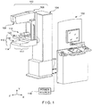
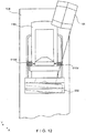
- Figs. 1-6 illustrate a non-limiting example of a multi-mode mammography/ tomosynthesis system comprising a gantry 100 and a data acquisition work-station 102.
- Gantry 100 includes a housing 104 supporting a tube arm assembly 106 rotatably mounted thereon to pivot about a horizontal axis 402 ( Fig. 4 ) and carrying an x-ray tube assembly 108.
- X-ray tube assembly 108 includes (1) an x-ray tube generating x-ray energy in a selected range, such as 20-50 kV, at mAs such as in the range 3-400 mAs, with focal spots such as a nominal size 0.3 mm large spot and nominal size 0.1 mm small spot (2) supports for multiple filters such as molybdenum, rhodium, aluminum, copper, and tin filters, and (3) an adjustable collimation assembly selectively collimating the x-ray beam from the focal spot in a range such as from 7x8 cm to 24x29 when measured at the image plane of an x-ray image receptor included in the system, at a maximum source-image distance such as 75 cm.
- a selected range such as 20-50 kV
- focal spots such as a nominal size 0.3 mm large spot and nominal size 0.1 mm small spot
- supports for multiple filters such as molybdenum, rhodium, aluminum, copper, and tin filters
- an adjustable collimation assembly selectively
- a compression arm assembly 110 that comprises a compression plate 122 and a receptor housing 114 having an upper surface 116 serving as a breast plate and enclosing a detector subsystem system 117 comprising a flat panel x-ray receptor 502 ( Fig. 5 ), a retractable anti-scatter grid 504 and a mechanism 506 for driving and retracting anti-scatter grid 504.
- Housing 104 also encloses the following components schematically illustrated in Fig.
- housing 104 also encloses suitable motors and electrical and mechanical components and connections to implement the functions discussed here.
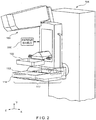
- a patient shield 200 can be secured to compression arm assembly 110 to provide a mechanical interlock against patient contact with the rotating x-ray tube arm assembly 106 and reduce patient interference with the x-ray image capture.
- One exemplary patient shield is a shifting patient shield that is positioned generally parallel to but outside the path of x-ray beams from source 108.
- the shifting face shield is supported by an extension arm that extends laterally from the compression arm assembly and permits movement of the face shield along a z axis.
- the patient shield may be removably secured either to the extension arm, compression arm assembly or the x-ray source assembly 108 to facilitate removal and/or replacement of shields for different imaging modes.
- the face shield may be of fixed size, or may be adjustably sized.
- An example of an adjustable face shield is disclosed in U.S. 7,315,607 , where the face shield is positioned to slide vertically along a y-axis, as indicated by arrow 201, up into the x-ray assembly. The vertical movement removes the face shield to allow for patient positioning as well as allows the shield to be selectively positioned to provide shields of different sizes for different imaging modes.
- Alternate embodiments are also envisioned wherein the face shield is programmed to shift laterally along an x-axis in response to a selection of a particular imaging mode. Such an embodiment is described in U.S. patent 7,245,694 issued July 17, 2007 to Hologic Inc..
- different shields or shield arrangements may be used in a system of the present invention which supports a combination imaging mode, wherein the shield is removable or moves, either automatically or manually, between at least two positions for at least two different imaging modes.
- Work-station 102 comprises components similar to those in the SeleniaTM mammography system, including a display screen (typically a flat panel display that may include touch-screen functionality), user interface devices such as a keyboard, possibly a touch-screen, and a mouse or trackball, and various switches and indicator lights and/or displays. Work-station 102 also includes computer facilities similar to those of the SeleniaTM system (but adapted through hardware, firmware and software differences) for controlling gantry 100 and for processing, storing and displaying data received from gantry 100.
- a power generation facility for x-ray tube assembly 108 may be included in housing 104 or in work-station 102.
- a power source 118 powers work-station 102.
- Gantry 100 and work-station 102 exchange data and controls over a schematically illustrated connection 120.
- additional storage facilities 602 can be connected to work-station 102, such as one or more optical disc drives for storing information such as images and/or for providing information to work-station 102 such as previously obtained images and software, or a local printer (not shown).
- work-station 102 such as one or more optical disc drives for storing information such as images and/or for providing information to work-station 102 such as previously obtained images and software, or a local printer (not shown).
- the disclosed system can be connected to a hospital or local area or other network 604, and through the network to other systems such as a soft copy workstation 606, a CAD (Computer Aided Detection) station 608 for computer- processing mammography and/or tomosynthesis images to identify likely abnormalities, an image printer 610 for printing images, a technologist workstation 612, other imaging systems 614 such as other mammography systems or systems for other modalities for exchange of images and/or other information, and to a PACS (Picture Archiving) systems 616 for archiving images and other information and/or retrieving images and other information.
- CAD Computer Aided Detection
- PACS Picture Archiving
- the illustrated system has several modes of operation.
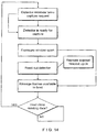
- An example of typical workflow generally applicable for each mode is illustrated in Fig. 7 , and several examples of operational modes are discussed below. Of course, this is only one example and workflow steps may be arranged differently.
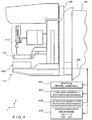
- the operator can perform x-ray exposure using manual setting of technic factors such as mA and mSec, or can use an Automatic Exposure Control (AEC) method as known in the art to set the exposure time, kV and filter modes for an image, for example by using a short, low-x-ray dose pre-exposure.
- AEC Automatic Exposure Control
- Work-station 102 is set up to record the exposure technic information and associate it with the breast image for later review.
- AEC Automatic Exposure Control
- a short (e.g., ⁇ 5 msec) an x-ray is taken (either at a low dose, or full dose) and the image receptor's image is read by a computer process.
- This initial x-ray is often referred to as a 'scout' image.
- the computer process uses information from the scout image to identify the breast's radio-density and to calculate the correct final x-ray tube exposure voltage kVp, current mAs, and exposure time for delivering a desired x-ray dose be obtained prior to performing mammography or tomosynthesis.
- the mammogram exposure data may be used to estimate tomosynthesis exposure techniques.
- a first tomosynthesis image may be used to as the 'scout' image to estimate the appropriate exposure factors for the remaining images in the tomosynthesis sequence.
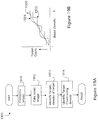
- Lookup tables have historically been used to identify appropriate kVp and mAs for desired exposures using scout or mammogram images. Look-up tables are reliable in 2D mammography systems which position the x-ray source normal to the detector and utilize anti-scatter grids to minimize radiographic scatter. In such systems the detector count rate may be fixed, with exposure dosing being controlled by varying the kVp and mAs. However tomosynthesis systems which do not maintain a constant perpendicular relationship between the receptor and the x-ray source are not able to use an anti-scatter grid.
- the present invention recognizes that such systems may benefit from improved exposure control techniques having the ability to vary the target detector count to compensate for radiographic scatter, where the detector count relates a count of photons to a desired x-ray dose.
- the detector count may be varied in accordance with a thickness of the imaged breast.
- Varying the detector count in accordance with breast thickness ensures that image quality of the breasts is maintained despite increased scatter.
- the table shows particular multipliers applied to the target counts for different breast thicknesses, it should be appreciated that the invention is not limited to any particular multipliers.
- several different AEC techniques and/or parameters may be used during a single sweep of the x-ray tube assembly arm (or between different sweeps of the x-ray tube assembly).
- the table illustrates that a common kV, mA and count is provided for a given thickness
- the AEC values may be customized for different imaging positions along the tomosynthesis path to accommodate for different types of radiographic scatter resulting from different x-ray source/receptor angular relationships, whether the imaging positions be associated with different imaging modes (such as mammography and tomosynthesis) or within the same imaging mode (i.e., different tomosynthesis imaging angles).
- tube arm assembly 106 and compression arm assembly 110 are coupled and locked together by 410 in a relative position such as seen in Fig. 1 , such that an x-ray beam from x-ray tube assembly 108 illuminates x-ray receptor 502 when the patient's breast is compressed by compression device 112.
- the system operates in a manner similar to said SeleniaTM system to take a mammogram.
- Vertical travel assembly 404 and tube arm rotation mechanism 406 can make vertical adjustments to accommodate a patient, and can rotate tube arm assembly 106 and compression arm assembly 110 together as a unit about axis 402 for different image orientations such as for CC and for MLO images.
- tube arm assembly 106 and compression arm assembly 110 can rotate between (-195°) and (+150°) about axis 402.
- compression device 112 includes a compression paddle 122 that can move laterally, in a direction along the chest wall of a patient, to adjust for different imaging orientations.
- the mechanism for supporting and moving compression paddle 122 is different.
- anti-scatter grid 504 is over x-ray receptor 502 in the standard mammography mode to reduce the effect of x-ray scatter.
- Fig. 8 illustrates a typical workflow for an exposure in standard mammography mode
- Fig. 10 illustrates an example of the operation of detector subsystem 117 in standard mammography. Of course, these are only examples; other workflow steps or orders of steps can be used instead.
- the patient's breast can be spaced from upper surface 116, for example by an x-ray translucent spacer gantry 1002 ( Fig. 10 ), with the system otherwise similar to Fig. 1 , for a magnification of up to 1.8, for example.
- tube arm assembly 106 and compression arm assembly 110 are locked to each other and can move up or down and rotate about axis 402 for different image orientation.
- a different spacer 1002 can be used for a different degree of magnification.
- differently shaped or dimensioned compression paddles 122 can be used for different breast compression effects.
- the x-ray tube in x-ray tube assembly 108 can be set to a smaller focal spot size to improve a diagnostic image.
- anti-scatter grid 504 typically is retracted or otherwise removed when magnification is used such that grid 504 is completely out of the image.
- the user can elect not to use a spacer 1002 in diagnostic imaging, in which case anti-scatter grid 504 can be used over the entire image.
- a number of breast images are taken while the patient's breast remains compressed.
- an agent such as iodine is injected into the patient and after a suitable waiting time such as about one minute for a maximum uptake, two images breast are taken in rapid succession, for example one at an x-ray energy just above the K-edge of iodine and one at an energy just below the K-edge.
- a succession of breast images can be taken at a single x-ray energy band or bands just above and below the K-edge, or at another x-ray energy range, to track the uptake of agent over time.
- Still another dynamic imaging mode technique comprises injecting a contrast agent and taking a succession of images over a period such as 5-7 minutes, for example one image every minute, and processing the image data to generate for each pixel, or at least for each pixel of interest, a histogram of the change in the pixel value, to thereby use the manner in which pixel values change to differential abnormal tissue.
- work-station 102 can store preset data that commands gantry 100 and work-station 102 to take a desired sequence of images for the dynamic mode technique selected by the operator, such that the command data sets the appropriate parameters such as x-ray energy, dose, timing of images, etc.
- processing to assess changes in pixel values can be done for a region of interest rather than over individual pixels, to produce information such as a measure of changes in the average pixel values in the region of interest.
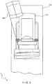
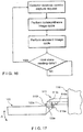
- tube arm assembly 106 and compression arm assembly 110 are decoupled by unit 410 such that compression arm assembly 110 stays in one position, compressing the patient's breast, while tube arm assembly 106 rotates about axis 402, for example between the position illustrated in Fig. 2 to that illustrated in Fig. 11 , or ⁇ 15° relative to compression arm assembly 110.
- the x-ray tube assembly rotates in an arc shaped path within a plane although this is not a requirement of the invention.
- Tomosynthesis can be carried out for different image orientations, so that compression arm assembly 110 can be rotated about axis 402 (alone or together with assembly 106) for a desired image orientation and locked in place, and then tube arm assembly 106 can be rotated relative to that position of compression arm assembly 110 for tomosynthesis imaging over ⁇ 15° or some other desired angular range.
- 11 images are taken during an angular sweep of tube arm assembly 106, one every approximately 3°.
- a different number of images can be taken, for example up to 21 during a single sweep.
- the x-ray tube in x-ray tube assembly 108 continuously rotates and the x-ray tube is pulsed for each image, for example, for x-ray energy pulses each lasting approximately 100 mSec, although pulses of different duration can be selected.
- the rotational motion can stop for taking each image, or continuous motion without pulsing can be used (and the timing of data measurements relied to define pixel values).
- this mode mechanism 506 fully retracts anti-scatter grid 504 away from x-ray receptor 502 so grid 504 is out of the image.
- Alternate methods of removing the anti-scatter grid from the image such as ejecting the grid out of a side of the receptor housing 114 or otherwise accessing and removing the grid are also contemplated by this invention.
- the x-ray receptor 502 rocks within receptor housing 114. In this rocking motion, controlled by unit 408 ( Fig. 4 ), a line normal to the image face of x-ray receptor 502 may keep pointing to the focal spot of the x-ray tube in x-ray tube assembly 108.
- the rotation of tube arm assembly 106 and rocking of x-ray receptor 502 can be through different angles; for example, tube arm assembly 106 can rotate through 15° while x-ray receptor 502 rocks through 5°, i.e. the rocking angle can be an amount one-third that of assembly 108.
- the receptor 502 rocks in concert with, but with a smaller angular displacement, from the x-ray tube assembly.
- the present invention is not limited to any particular fractional angular relationship between the assembly and the receptor, and the present invention envisions systems wherein the detector is stationary during imaging.
- Synchronous rotation of tube arm assembly 106 and rocking of x-ray receptor 502 can be achieved by controlling separate motors for each or, alternatively, through using a motor to drive tube arm assembly 106 and a mechanical coupling between the rotation of tube arm assembly 106 and rocking of x-ray receptor 502.
- Image data can be obtained and processed into tomosynthesis images for display and/or storage as described for example in co-pending patent application Ser. No. 10/723,486 or in U.S Provisional Application No. 60/628,516 , filed November 15, 2004.
- Fig. 13 illustrates a typical workflow for tomosynthesis mode operation
- Fig. 14 illustrates an example of the operation of detector subsystem 117 in that mode. Again, these are only examples, and other steps or orders of steps can be used instead.
- the receptor rocks such that it is positioned offset from normal to the x-ray source, this is not a requirement of the invention. Alternate embodiments where the receptor rotates along the same angular displacement and synchronous to the x-ray source are also contemplated. In addition, embodiments where the x-ray receptor moves linearly or laterally in a plane, rather than rocking, are within the scope of the present invention. In addition, in embodiments wherein the x-ray source assumes a non-arc shaped path, systems wherein the receptor rotates or tilts in a manner related to the x-ray source movement are contemplated by the present invention. Of course other embodiments wherein the detector remains stationary are also contemplated by this invention.
- a combination mode during a single compression of the patient's breast the system takes a conventional mammogram and tomosynthesis images.
- tube arm assembly 106 sweeps and x-ray receptor 502 rocks, each through an appropriate angle, and exposures are taken for tomosynthesis images, and (2) a standard mammogram is taken.
- the standard mammogram can be taken at a 0° relative angle between tube arm assembly 106 and a normal to the imaging plane of x-ray receptor 502, and can be taken before or after the tomosynthesis images are taken or between the taking of two successive tomosynthesis images.
- each tomosynthesis image utilizes substantially lower x-ray dose than the standard mammogram.
- the total x-ray dosage for tomosynthesis imaging in one sweep of tube arm assembly 106 can be approximately the same as that for a single standard mammogram, or up to approximately three times that dosage.
- the relationship between the two dosages can be user-selected.
- Figure 15 illustrates an example of workflow for the combination mode
- Fig. 16 illustrates an example of the operation of detector subsystem 117 in that mode. Again, these are examples, and different steps or orders of steps can be used instead.
- a preferred approach may be to take the standard mammogram first, then move arm 106 to one end of its rotational range for tomosynthesis and take the tomosynthesis images.
- the order in which the two types of images are taken may be optimized such that the overall imaging time is minimized, and an order that achieves such minimization can be the preferred order.
- the exposure (tube current mA, tube voltage kVp, and exposure length msec) techniques for the standard mammogram and the tomosynthesis exposures can be set manually, by using automatic methods or using the methods described above. If the standard mammogram is taken first, its exposure techniques can be used to set an optimal technique for the subsequent tomosynthesis images, and vice versa.
- the exposure technique can be modified dynamically, if the software senses that the signal reaching the image receptor is either too low or too high and adjust subsequent exposures as needed.
- X-ray receptor 502 can remain in place for this procedure, or can be rocked through a selected angle, for example through an angle sufficient to maintain the same orientation of the imaging surface of receptor 502 relative to tube arm assembly 106.
- a spacer 1002 can be used for magnification.
- the two or more images can be used to identify the location of a lesion, so that needle biopsy can be used, for example with an upright needle biopsy station 412 ( Fig. 4 ) in a manner similar to that used with the commercially available SeleniaTM system and StereoLoc IITM.
- a compression paddle 122 appropriate for needle biopsy typically is used when taking the stereotactic images.
- some or all of the images taken in the tomosynthesis mode and/or in the combined mode can be used to identify the location of a lesion for biopsy, in which case a compression paddle 122 appropriate for the purpose typically is used when taking the images.
- x-ray images can be taken after a biopsy or other needle is inserted into the compressed breast.
- imaging such as in the stereotactic mode, the tomosynthesis mode, or the combined mode can be used.
- compression paddle 122 is movable laterally, as generally described in co-pending U.S. Patent Application Publication No. 2005/0063509 A1 .
- compression paddle 122 can pivot about an axis along the patient's chest wall to conform the breast shape in certain procedures, as discussed in said U.S. Patent 5,706,327 .
- compression paddle 122 is mounted differently and moves in a different manner.
- compression paddle 122 is removably mounted to a support 510 that moves up and down compression arm assembly 110 as needed for breast compression.
- a projection compression paddle 122a of the paddle engages a projection 510a of the support, and a projection 122b of the paddle latches onto projection 510b of the support.
- Projection 510a is springloaded, such as by a spring schematically illustrates at 510c to allow for pivoting compression paddle 122 about an axis where it latches onto 510, as illustrated by arrow A, for better conformance with the compressed breast in some imaging protocols.
- Imaging protocols may require compression paddle 122 not to pivot, in which case projection 510a is locked in place by a locking mechanism in 510 (not shown) to keep compression paddle 122 in place relative to support 510.
- the locking mechanism can be manually set to a lock position, and manually unlocked by the operator. Alternatively, the locking mechanism can be controlled through an operator input at gantry 100 or work-station 102.
- a sensing mechanism can be included to sense whether compression paddle 122 is locked against pivoting, to provide information that work-station 102 can use for setting imaging protocols such as for automated breast compression and automated exposure methods.
- Two knobs 510d can be manually rotated to move projection 510b and thus compression paddle 122 laterally such that it compress a breast that is not centered laterally on upper surface 116, for example for MLO imaging.
- Each knob 510d can operate a mechanism such as an endless screw rotating in a nut secured to projection 510b.
- projection 510b and thus compression paddle 122 can be driven laterally by a motor, under control of operator switches or other interface at gantry 100 or at work-station 102, or automatically positioned laterally under computer control.
- compression paddle 122 is driven for lateral movement by components that are a part of support 510.
- compression paddle 122 can be simple structure, and can even be disposable, with a new one used for each patient or for only a few patients. This can simplify and reduce the cost of using the system, because an imaging facility usually stocks a number of different paddles for different purposes. If the lateral movement mechanism is integral with a compression paddle, the paddle assembly is considerably larger, heavier and more expensive.
- Compression paddle 122 can include a bar code that is automatically read by a bar code reader in support 510, to keep work-station 102 informed of the paddle currently mounted to support 510, for use in automating imaging protocols.
- the bar code information can be checked to ensure through computer processing that the type of paddle that is currently mounted on support 510 matches the imaging that will be commanded, and the information from the sensor for whether compression paddle 122 is locked in non-tilting mode can be used to automatically make adjustments for compression height to ensure accurate automatic x-ray exposure operation. Further, the bar code information identifying the paddle can be used to automatically set collimation in x-ray tube assembly 108 so that the x-ray beam matches the size and shape of the currently installed compression paddle 122.
- the imaging modalities include, but are not limited to, mammography, dynamic imaging mode, diagnosis mode, tomosynthesis, combination mode and stereotactic mode.
- the system facilitates imaging protocols wherein at least one imaging mode differs from at least one other imaging mode for at least one imaging capture procedure selected from a group including, but are not limited to receptor motion, x-ray source location, anti-scatter grid use, exposure control and patient shielding.
- the system further supports a combination imaging mode wherein images are captured using at least two imaging modes during a single image scan and wherein each of the at least two imaging modes differs by at least one image capture procedure during the single scan.
Claims (7)
- Système d'imagerie par rayons X pour mammographie multi-mode comprenant:une source de rayons X (108);un détecteur de rayons X, conçu pour fournir un comptage de photons;une grille anti-diffusion amovible,dans lequel la source de rayons X et le détecteur de rayons X sont configurés pour réaliser un unique balayage d'image qui génère des images durant une unique compression du sein à l'aide d'au moins deux modes d'imagerie différents,dans lequel dans au moins l'un desdits modes d'imagerie, la grille anti-diffusion est retirée,et dans lequel le système d'imagerie est agencé pour appliquer un contrôle d'exposition par utilisation d'une dose de rayons X souhaitée, pour prendre (1912) une image de repérage et identifier à partir de l'image de repérage (1914) la densité d'un sein de patiente,caractérisé par le fait que le système d'imagerie est en outre agencé pour identifier (1916) un comptage cible de détecteur en utilisant la densité identifiée, le comptage cible de détecteur portant sur un comptage de photons à ladite dose de rayons X souhaitée.
- Système d'imagerie par rayons X pour mammographie multi-mode selon la revendication 1, dans lequel le détecteur de rayons X est conçu pour se balancer dans au moins un mode d'imagerie et de préférence est conçu pour se balancer le long d'un déplacement angulaire qui est inférieur à un déplacement angulaire de la source de rayons X dans l'au moins un mode d'imagerie.
- Système d'imagerie par rayons X pour mammographie multi-mode selon l'une quelconque des revendications précédentes, dans lequel un bras de compression est disposé entre la source de rayons X et le détecteur de rayons X pour une compression d'un sein de patiente.
- Système d'imagerie par rayons X pour mammographie multi-mode selon l'une quelconque des revendications précédentes, dans lequel les modes d'imagerie diffèrent en ce qui concerne une procédure d'imagerie choisie parmi un groupe comprenant un mouvement de détecteur, un contrôle d'exposition et une protection de patient.
- Système d'imagerie par rayons X pour mammographie multi-mode selon la revendication 4, dans lequel la protection de patiente est retirée dans au moins un mode d'imagerie.
- Système d'imagerie par rayons X pour mammographie multi-mode selon la revendication 4, dans lequel une dimension de l'écran pour patient diffère pour au moins deux modes d'imagerie.
- Système d'imagerie par rayons X pour mammographie multi-mode selon la revendication 4 ou la revendication 6, dans lequel l'écran pour patient est positionné différemment pour au moins deux modes d'imagerie.
Priority Applications (1)
| Application Number | Priority Date | Filing Date | Title |
|---|---|---|---|
| EP17200339.4A EP3311748A3 (fr) | 2008-09-04 | 2009-09-04 | Système de rayons x pour mammographie/tomosynthèse multi-mode intégré |
Applications Claiming Priority (2)
| Application Number | Priority Date | Filing Date | Title |
|---|---|---|---|
| US9432008P | 2008-09-04 | 2008-09-04 | |
| PCT/US2009/055981 WO2010028208A1 (fr) | 2008-09-04 | 2009-09-04 | Système de rayons x pour mammographie/tomosynthèse multi-mode intégré et procédé afférent |
Related Child Applications (1)
| Application Number | Title | Priority Date | Filing Date |
|---|---|---|---|
| EP17200339.4A Division EP3311748A3 (fr) | 2008-09-04 | 2009-09-04 | Système de rayons x pour mammographie/tomosynthèse multi-mode intégré |
Publications (2)
| Publication Number | Publication Date |
|---|---|
| EP2326248A1 EP2326248A1 (fr) | 2011-06-01 |
| EP2326248B1 true EP2326248B1 (fr) | 2017-11-08 |
Family
ID=41256058
Family Applications (2)
| Application Number | Title | Priority Date | Filing Date |
|---|---|---|---|
| EP17200339.4A Withdrawn EP3311748A3 (fr) | 2008-09-04 | 2009-09-04 | Système de rayons x pour mammographie/tomosynthèse multi-mode intégré |
| EP09792256.1A Active EP2326248B1 (fr) | 2008-09-04 | 2009-09-04 | Système de rayons x pour mammographie/tomosynthèse multi-mode intégré |
Family Applications Before (1)
| Application Number | Title | Priority Date | Filing Date |
|---|---|---|---|
| EP17200339.4A Withdrawn EP3311748A3 (fr) | 2008-09-04 | 2009-09-04 | Système de rayons x pour mammographie/tomosynthèse multi-mode intégré |
Country Status (8)
| Country | Link |
|---|---|
| EP (2) | EP3311748A3 (fr) |
| JP (7) | JP2012501750A (fr) |
| KR (1) | KR20110063659A (fr) |
| CN (1) | CN102196772A (fr) |
| AU (1) | AU2009289574B2 (fr) |
| CA (1) | CA2735935C (fr) |
| DE (1) | DE202009018884U1 (fr) |
| WO (1) | WO2010028208A1 (fr) |
Cited By (2)
| Publication number | Priority date | Publication date | Assignee | Title |
|---|---|---|---|---|
| US11253208B2 (en) | 2019-07-26 | 2022-02-22 | Fujifilm Corporation | Tomosynthesis imaging control device, method for operating tomosynthesis imaging control device, and program for operating tomosynthesis imaging control device |
| US11284845B2 (en) | 2019-07-26 | 2022-03-29 | Fujifilm Corporation | Tomosynthesis imaging control device, method for operating tomosynthesis imaging control device, program for operating tomosynthesis imaging control device, and radiation source |
Families Citing this family (57)
| Publication number | Priority date | Publication date | Assignee | Title |
|---|---|---|---|---|
| WO2007095330A2 (fr) | 2006-02-15 | 2007-08-23 | Hologic Inc | Biopsie mammaire et localisation a l'aiguille a l'aide de systemes de tomosynthese |
| CN102481146B (zh) | 2009-10-08 | 2016-08-17 | 霍罗吉克公司 | 乳房的穿刺活检系统及其使用方法 |
| US8571174B2 (en) | 2010-09-09 | 2013-10-29 | Hologic, Inc. | Methods and systems for detecting possible error in patient position |
| US8845190B2 (en) * | 2010-10-06 | 2014-09-30 | Carestream Health, Inc. | Low-dose automatic exposure control system for digital portable X-ray imaging |
| WO2012071429A1 (fr) | 2010-11-26 | 2012-05-31 | Hologic, Inc. | Interface d'utilisateur pour station de travail de visualisation d'images médicales |
| KR101297081B1 (ko) * | 2011-01-19 | 2013-08-19 | 한국전기연구원 | 병변 진단 장치 및 방법 |
| JP6057922B2 (ja) * | 2011-03-08 | 2017-01-11 | ホロジック, インコーポレイテッドHologic, Inc. | スクリーニング、診断及び生検のための二重エネルギー及び/又は造影強化乳房撮像のためのシステム及び方法 |
| KR101337489B1 (ko) * | 2011-06-30 | 2014-01-16 | 주식회사 휴먼레이 | 다기능 맘모그래피 장치 |
| KR101340456B1 (ko) * | 2011-06-30 | 2013-12-11 | 주식회사 휴먼레이 | 다중 센서를 갖는 맘모그래피용 디텍터 및 3차원 영상 획득이 가능한 맘모그래피 장치 |
| EP2727534A4 (fr) | 2011-07-01 | 2015-04-29 | Rayence Co Ltd | Détecteur de mammographie ayant de multiples capteurs, et dispositif de mammographie apte à une acquisition d'images tridimensionnelles (3d) |
| JP5897020B2 (ja) * | 2011-09-27 | 2016-03-30 | 富士フイルム株式会社 | 放射線撮影システムおよびその作動方法、並びに放射線画像検出装置 |
| JP2014534042A (ja) | 2011-11-27 | 2014-12-18 | ホロジック, インコーポレイテッドHologic, Inc. | マンモグラフィーおよび/またはトモシンセシス画像データを使用して2d画像を生成するためのシステムおよび方法 |
| JP6240097B2 (ja) | 2012-02-13 | 2017-11-29 | ホロジック インコーポレイティッド | 合成画像データを使用してトモシンセシススタックをナビゲートする方法 |
| KR102043799B1 (ko) | 2012-12-27 | 2019-11-12 | 제네럴 일렉트릭 컴퍼니 | X선 촬영장치 |
| KR102090597B1 (ko) | 2012-12-28 | 2020-03-19 | 삼성전자주식회사 | 엑스선 촬영 장치 및 엑스선 영상 처리 방법 |
| US10092358B2 (en) | 2013-03-15 | 2018-10-09 | Hologic, Inc. | Tomosynthesis-guided biopsy apparatus and method |
| WO2015061582A2 (fr) | 2013-10-24 | 2015-04-30 | Smith Andrew P | Système et procédé de navigation pour une biopise du sein guidée par rayons x |
| EP3110332B1 (fr) | 2014-02-28 | 2018-04-11 | Hologic Inc. | Système et procédé de production et d'affichage de dalles d'image de tomosynthèse |
| CN105193436B (zh) * | 2014-06-20 | 2018-04-20 | 深圳市蓝韵实业有限公司 | 数字乳腺x射线成像系统曝光剂量的评价方法 |
| US10603002B2 (en) | 2014-11-07 | 2020-03-31 | Hologic, Inc. | Pivoting paddle apparatus for mammography/tomosynthesis X-ray system |
| DE102015200180A1 (de) | 2015-01-09 | 2016-07-14 | Siemens Healthcare Gmbh | Verfahren zur Aufnahme eines Tomosynthesedatensatzes mit einer Röntgeneinrichtung und Röntgeneinrichtung |
| CN105147309A (zh) * | 2015-09-28 | 2015-12-16 | 上海联影医疗科技有限公司 | 一种乳腺摄影系统及方法 |
| JP2018186842A (ja) * | 2015-09-29 | 2018-11-29 | 富士フイルム株式会社 | 制御装置、放射線画像撮影装置、放射線画像撮影方法、及び放射線画像撮影プログラム |
| EP3534795B1 (fr) * | 2016-11-04 | 2021-01-13 | Hologic, Inc. | Dispositif d'imagerie médicale |
| US10888292B2 (en) | 2016-11-08 | 2021-01-12 | Hologic, Inc. | Imaging with curved compression elements |
| AU2017363889B2 (en) * | 2016-11-25 | 2023-06-08 | Hologic, Inc. | Controller for imaging apparatus |
| JP6656199B2 (ja) | 2017-03-30 | 2020-03-04 | 富士フイルム株式会社 | マンモグラフィ装置 |
| US11445993B2 (en) | 2017-03-30 | 2022-09-20 | Hologic, Inc. | System and method for targeted object enhancement to generate synthetic breast tissue images |
| CN110621233B (zh) | 2017-03-30 | 2023-12-12 | 豪洛捷公司 | 用于处理乳房组织图像数据的方法 |
| CN110621231B (zh) | 2017-03-30 | 2024-02-23 | 豪洛捷公司 | 用于分层次多级特征图像合成和表示的系统以及方法 |
| EP3641635A4 (fr) | 2017-06-20 | 2021-04-07 | Hologic, Inc. | Procédé et système d'imagerie médicale à auto-apprentissage dynamique |
| EP3420908A1 (fr) * | 2017-06-27 | 2019-01-02 | Koninklijke Philips N.V. | Détection de rayons x diffusés pour détecter le mauvais usage et de prévenir les dommages |
| JP7074782B2 (ja) * | 2017-06-30 | 2022-05-24 | トロフィー エスアーエス | 患者位置決めアクセサリ検出を伴う口腔外歯科用撮像装置 |
| JP6823178B2 (ja) * | 2017-07-19 | 2021-01-27 | 富士フイルム株式会社 | マンモグラフィ装置、放射線画像撮影システム、画像処理装置、制御方法、画像処理方法、制御プログラム、及び画像処理プログラム |
| WO2019022246A1 (fr) * | 2017-07-27 | 2019-01-31 | 富士フイルム株式会社 | Système d'imagerie radiographique, dispositif de commande, procédé de commande et programme de commande |
| WO2019033029A1 (fr) | 2017-08-11 | 2019-02-14 | Hologic, Inc. | Plaque de compression du sein pourvue de coins d'accès |
| WO2019033022A1 (fr) | 2017-08-11 | 2019-02-14 | Hologic, Inc. | Plaque de compression du sein pourvue d'une enveloppe gonflable |
| EP3668404B1 (fr) | 2017-08-16 | 2022-07-06 | Hologic, Inc. | Techniques de compensation d'artéfact de mouvement de patient en imagerie du sein |
| CN108634972A (zh) * | 2018-05-14 | 2018-10-12 | 北京达影科技有限公司 | 数字乳腺体层合成系统和方法 |
| JP7317051B2 (ja) * | 2018-05-25 | 2023-07-28 | ホロジック, インコーポレイテッド | 圧迫アームデバイスおよび方法 |
| US20190370956A1 (en) * | 2018-05-30 | 2019-12-05 | General Electric Company | Contrast imaging system and method |
| EP3616624B1 (fr) * | 2018-08-28 | 2021-04-28 | Siemens Healthcare GmbH | Procédé de fonctionnement d'un dispositif à rayons x, dispositif à rayons x, programme informatique et support d'informations lisible électroniquement |
| US20210401381A1 (en) * | 2018-09-25 | 2021-12-30 | Hologic, Inc. | Light assemblies and methods for mammography and tomosynthesis imaging systems |
| JP7043381B2 (ja) | 2018-09-27 | 2022-03-29 | 富士フイルム株式会社 | トモシンセシス撮影装置及びその作動方法 |
| JP7086805B2 (ja) | 2018-09-27 | 2022-06-20 | 富士フイルム株式会社 | トモシンセシス撮影装置とその作動方法 |
| JP6995727B2 (ja) | 2018-09-27 | 2022-01-17 | 富士フイルム株式会社 | トモシンセシス撮影装置とその作動方法 |
| JP7043380B2 (ja) | 2018-09-27 | 2022-03-29 | 富士フイルム株式会社 | トモシンセシス撮影装置及びその作動方法 |
| JP7184584B2 (ja) | 2018-09-27 | 2022-12-06 | 富士フイルム株式会社 | 放射線撮影装置 |
| EP3886703B1 (fr) * | 2018-11-30 | 2023-12-20 | Accuray, Inc. | Procédé et appareil pour améliorer l'estimation et la correction de diffusion en imagerie |
| JP7294592B2 (ja) * | 2018-12-03 | 2023-06-20 | ザ ユニバーシティ オブ ノース カロライナ アット チャペル ヒル | トモシンセシス、蛍光透視、及び定位イメージングのためのコンパクトx線デバイス、システム、及び方法 |
| JP7190939B2 (ja) * | 2019-02-28 | 2022-12-16 | 富士フイルム株式会社 | 放射線画像撮影システム、制御方法、及び制御プログラム |
| US11883206B2 (en) | 2019-07-29 | 2024-01-30 | Hologic, Inc. | Personalized breast imaging system |
| WO2021062284A1 (fr) | 2019-09-27 | 2021-04-01 | Hologic, Inc. | Système d'intelligence artificielle (ai) permettant de prédire le temps de lecture et la complexité de lecture pour examiner des images de sein en 2d/3d |
| CN115003228A (zh) | 2020-01-24 | 2022-09-02 | 豪洛捷公司 | 可水平移位的泡沫乳房压缩桨 |
| US11481038B2 (en) | 2020-03-27 | 2022-10-25 | Hologic, Inc. | Gesture recognition in controlling medical hardware or software |
| US11308594B2 (en) * | 2020-05-15 | 2022-04-19 | GE Precision Healthcare LLC | Tomosynthesis dataset generation using pre-exposure acquisition |
| JP7446454B2 (ja) | 2020-09-28 | 2024-03-08 | 富士フイルム株式会社 | 情報処理装置、情報処理装置の作動方法、及び情報処理プログラム |
Citations (1)
| Publication number | Priority date | Publication date | Assignee | Title |
|---|---|---|---|---|
| US7245694B2 (en) * | 2005-08-15 | 2007-07-17 | Hologic, Inc. | X-ray mammography/tomosynthesis of patient's breast |
Family Cites Families (32)
| Publication number | Priority date | Publication date | Assignee | Title |
|---|---|---|---|---|
| US1179160A (en) | 1914-11-06 | 1916-04-11 | Burton & Richardson | Cutting-roll. |
| JPS5753531Y2 (fr) * | 1977-05-04 | 1982-11-19 | ||
| FR2512024A1 (fr) | 1981-08-27 | 1983-03-04 | Adir | Ethers tricycliques, leur preparation et les compositions pharmaceutiques les contenant |
| US5051904A (en) | 1988-03-24 | 1991-09-24 | Olganix Corporation | Computerized dynamic tomography system |
| US5359637A (en) | 1992-04-28 | 1994-10-25 | Wake Forest University | Self-calibrated tomosynthetic, radiographic-imaging system, method, and device |
| US5506877A (en) * | 1994-11-23 | 1996-04-09 | The General Hospital Corporation | Mammography breast compression device and method |
| US5706327A (en) | 1996-02-09 | 1998-01-06 | Trex Medical Corporation | Method and apparatus for mammographic compression |
| JPH10165403A (ja) * | 1996-12-13 | 1998-06-23 | Toshiba Corp | マンモ用バイオプシー装置 |
| US6289235B1 (en) | 1998-03-05 | 2001-09-11 | Wake Forest University | Method and system for creating three-dimensional images using tomosynthetic computed tomography |
| US6645520B2 (en) | 1999-12-16 | 2003-11-11 | Dermatrends, Inc. | Transdermal administration of nonsteroidal anti-inflammatory drugs using hydroxide-releasing agents as permeation enhancers |
| SE0004298D0 (sv) * | 2000-11-23 | 2000-11-23 | Siemens Elema Ab | Röntgendiagnostikapparat |
| FR2829918A1 (fr) * | 2001-09-25 | 2003-03-28 | Ge Med Sys Global Tech Co Llc | Appareil de mammographie |
| EP1444873A2 (fr) | 2001-10-19 | 2004-08-11 | Hologic, Inc. | Systeme et procede de mammographie utilisant des palpateurs de compression excentres, la collimation automatique et une grille anti-diffusion retractable |
| US7609806B2 (en) | 2004-10-18 | 2009-10-27 | Hologic Inc. | Mammography system and method employing offset compression paddles, automatic collimations, and retractable anti-scatter grid |
| US6647092B2 (en) | 2002-01-18 | 2003-11-11 | General Electric Company | Radiation imaging system and method of collimation |
| SE524380C2 (sv) * | 2002-03-12 | 2004-08-03 | Xcounter Ab | Exponeringsstyrning i scannerbaserad detektering av joniserande strålning |
| US6970531B2 (en) | 2002-10-07 | 2005-11-29 | General Electric Company | Continuous scan RAD tomosynthesis system and method |
| US6940943B2 (en) | 2002-10-07 | 2005-09-06 | General Electric Company | Continuous scan tomosynthesis system and method |
| US7110490B2 (en) * | 2002-12-10 | 2006-09-19 | General Electric Company | Full field digital tomosynthesis method and apparatus |
| US7319734B2 (en) * | 2003-04-11 | 2008-01-15 | Hologic, Inc. | Method and apparatus for blocking radiographic scatter |
| DE10353611B4 (de) * | 2003-11-17 | 2013-01-17 | Siemens Aktiengesellschaft | Röntgendiagnostikgerät für Mammographieuntersuchungen |
| SE528366C2 (sv) * | 2004-02-13 | 2006-10-31 | Sectra Mamea Ab | Metod och anordning avseende röntgenbildtagning |
| EP3106094B1 (fr) * | 2004-11-26 | 2021-09-08 | Hologic, Inc. | Systeme radiographique multimode integrant mammographie/tomosynthese |
| FR2882246B1 (fr) * | 2005-02-21 | 2007-05-18 | Gen Electric | Appareil de mammographie muni d'un ecran de protection de la tete d'un patient |
| DE102005022899A1 (de) * | 2005-05-18 | 2006-11-23 | Siemens Ag | Verfahren und Einrichtung zum Erzeugen eines digitalen tomosynthetischen 3D-Röntgenbildes von einem Untersuchungsobjekt |
| DE202005013910U1 (de) | 2005-09-02 | 2005-11-24 | Siemens Ag | Mammographiegerät mit Gesichtsschild |
| US7522608B2 (en) | 2005-11-01 | 2009-04-21 | Microsoft Corporation | Endpoint selection for a call completion response |
| JP4769097B2 (ja) * | 2006-03-01 | 2011-09-07 | 富士フイルム株式会社 | マンモグラフィ装置及び該マンモグラフィ装置に用いられる乳房圧迫板 |
| US20070223651A1 (en) * | 2006-03-21 | 2007-09-27 | Wagenaar Douglas J | Dual modality mammography device |
| JP2008067933A (ja) * | 2006-09-14 | 2008-03-27 | Toshiba Corp | デジタルマンモグラフィ装置 |
| JP4874755B2 (ja) * | 2006-09-29 | 2012-02-15 | 富士フイルム株式会社 | 放射線画像撮影装置 |
| JP4851296B2 (ja) * | 2006-10-26 | 2012-01-11 | 富士フイルム株式会社 | 放射線断層画像取得装置および放射線断層画像取得方法 |
-
2009
- 2009-09-04 WO PCT/US2009/055981 patent/WO2010028208A1/fr active Application Filing
- 2009-09-04 CN CN2009801423674A patent/CN102196772A/zh active Pending
- 2009-09-04 EP EP17200339.4A patent/EP3311748A3/fr not_active Withdrawn
- 2009-09-04 CA CA2735935A patent/CA2735935C/fr active Active
- 2009-09-04 DE DE202009018884.1U patent/DE202009018884U1/de not_active Expired - Lifetime
- 2009-09-04 AU AU2009289574A patent/AU2009289574B2/en active Active
- 2009-09-04 KR KR1020117007833A patent/KR20110063659A/ko not_active Application Discontinuation
- 2009-09-04 JP JP2011526216A patent/JP2012501750A/ja not_active Withdrawn
- 2009-09-04 EP EP09792256.1A patent/EP2326248B1/fr active Active
-
2013
- 2013-09-27 JP JP2013201895A patent/JP5792250B2/ja active Active
- 2013-09-27 JP JP2013005593U patent/JP3187716U/ja not_active Expired - Lifetime
-
2014
- 2014-07-09 JP JP2014141331A patent/JP2014184342A/ja not_active Withdrawn
-
2016
- 2016-04-26 JP JP2016087710A patent/JP6247717B2/ja active Active
-
2017
- 2017-02-03 JP JP2017018187A patent/JP6360923B2/ja active Active
-
2018
- 2018-03-12 JP JP2018043946A patent/JP2018086584A/ja not_active Withdrawn
Patent Citations (1)
| Publication number | Priority date | Publication date | Assignee | Title |
|---|---|---|---|---|
| US7245694B2 (en) * | 2005-08-15 | 2007-07-17 | Hologic, Inc. | X-ray mammography/tomosynthesis of patient's breast |
Cited By (2)
| Publication number | Priority date | Publication date | Assignee | Title |
|---|---|---|---|---|
| US11253208B2 (en) | 2019-07-26 | 2022-02-22 | Fujifilm Corporation | Tomosynthesis imaging control device, method for operating tomosynthesis imaging control device, and program for operating tomosynthesis imaging control device |
| US11284845B2 (en) | 2019-07-26 | 2022-03-29 | Fujifilm Corporation | Tomosynthesis imaging control device, method for operating tomosynthesis imaging control device, program for operating tomosynthesis imaging control device, and radiation source |
Also Published As
| Publication number | Publication date |
|---|---|
| WO2010028208A1 (fr) | 2010-03-11 |
| JP2012501750A (ja) | 2012-01-26 |
| KR20110063659A (ko) | 2011-06-13 |
| JP2013255844A (ja) | 2013-12-26 |
| CN102196772A (zh) | 2011-09-21 |
| CA2735935A1 (fr) | 2010-03-11 |
| JP5792250B2 (ja) | 2015-10-07 |
| JP2018086584A (ja) | 2018-06-07 |
| EP3311748A3 (fr) | 2018-05-09 |
| JP2017099928A (ja) | 2017-06-08 |
| JP6360923B2 (ja) | 2018-07-18 |
| JP2016135319A (ja) | 2016-07-28 |
| CA2735935C (fr) | 2017-07-25 |
| EP2326248A1 (fr) | 2011-06-01 |
| AU2009289574B2 (en) | 2015-06-18 |
| JP3187716U (ja) | 2013-12-12 |
| JP2014184342A (ja) | 2014-10-02 |
| EP3311748A2 (fr) | 2018-04-25 |
| AU2009289574A1 (en) | 2010-03-11 |
| JP6247717B2 (ja) | 2017-12-13 |
| DE202009018884U1 (de) | 2014-04-04 |
Similar Documents
| Publication | Publication Date | Title |
|---|---|---|
| US11617548B2 (en) | Integrated multi-mode mammography/tomosynthesis x-ray system and method | |
| EP2326248B1 (fr) | Système de rayons x pour mammographie/tomosynthèse multi-mode intégré | |
| US8565372B2 (en) | System and method for low dose tomosynthesis | |
| AU2017204458B2 (en) | Integrated multi-mode mammography/tomosynthesis x-ray system and method | |
| AU2013101288A4 (en) | Integrated multi-mode mammography/tomosynthesis x-ray system and method |
Legal Events
| Date | Code | Title | Description |
|---|---|---|---|
| PUAI | Public reference made under article 153(3) epc to a published international application that has entered the european phase |
Free format text: ORIGINAL CODE: 0009012 |
|
| 17P | Request for examination filed |
Effective date: 20110302 |
|
| AK | Designated contracting states |
Kind code of ref document: A1 Designated state(s): AT BE BG CH CY CZ DE DK EE ES FI FR GB GR HR HU IE IS IT LI LT LU LV MC MK MT NL NO PL PT RO SE SI SK SM TR |
|
| AX | Request for extension of the european patent |
Extension state: AL BA RS |
|
| DAX | Request for extension of the european patent (deleted) | ||
| 17Q | First examination report despatched |
Effective date: 20150708 |
|
| GRAP | Despatch of communication of intention to grant a patent |
Free format text: ORIGINAL CODE: EPIDOSNIGR1 |
|
| STAA | Information on the status of an ep patent application or granted ep patent |
Free format text: STATUS: GRANT OF PATENT IS INTENDED |
|
| INTG | Intention to grant announced |
Effective date: 20170316 |
|
| GRAS | Grant fee paid |
Free format text: ORIGINAL CODE: EPIDOSNIGR3 |
|
| GRAJ | Information related to disapproval of communication of intention to grant by the applicant or resumption of examination proceedings by the epo deleted |
Free format text: ORIGINAL CODE: EPIDOSDIGR1 |
|
| GRAL | Information related to payment of fee for publishing/printing deleted |
Free format text: ORIGINAL CODE: EPIDOSDIGR3 |
|
| STAA | Information on the status of an ep patent application or granted ep patent |
Free format text: STATUS: EXAMINATION IS IN PROGRESS |
|
| INTC | Intention to grant announced (deleted) | ||
| GRAR | Information related to intention to grant a patent recorded |
Free format text: ORIGINAL CODE: EPIDOSNIGR71 |
|
| STAA | Information on the status of an ep patent application or granted ep patent |
Free format text: STATUS: GRANT OF PATENT IS INTENDED |
|
| GRAA | (expected) grant |
Free format text: ORIGINAL CODE: 0009210 |
|
| STAA | Information on the status of an ep patent application or granted ep patent |
Free format text: STATUS: THE PATENT HAS BEEN GRANTED |
|
| INTG | Intention to grant announced |
Effective date: 20170906 |
|
| RIN1 | Information on inventor provided before grant (corrected) |
Inventor name: JING, ZHENXUE Inventor name: REN, BAORUI Inventor name: STEIN, JAY Inventor name: SMITH, ANDREW |
|
| AK | Designated contracting states |
Kind code of ref document: B1 Designated state(s): AT BE BG CH CY CZ DE DK EE ES FI FR GB GR HR HU IE IS IT LI LT LU LV MC MK MT NL NO PL PT RO SE SI SK SM TR |
|
| REG | Reference to a national code |
Ref country code: GB Ref legal event code: FG4D |
|
| REG | Reference to a national code |
Ref country code: CH Ref legal event code: EP Ref country code: AT Ref legal event code: REF Ref document number: 943380 Country of ref document: AT Kind code of ref document: T Effective date: 20171115 |
|
| REG | Reference to a national code |
Ref country code: IE Ref legal event code: FG4D |
|
| REG | Reference to a national code |
Ref country code: NL Ref legal event code: FP |
|
| REG | Reference to a national code |
Ref country code: DE Ref legal event code: R096 Ref document number: 602009049280 Country of ref document: DE |
|
| REG | Reference to a national code |
Ref country code: LT Ref legal event code: MG4D |
|
| REG | Reference to a national code |
Ref country code: AT Ref legal event code: MK05 Ref document number: 943380 Country of ref document: AT Kind code of ref document: T Effective date: 20171108 |
|
| PG25 | Lapsed in a contracting state [announced via postgrant information from national office to epo] |
Ref country code: LT Free format text: LAPSE BECAUSE OF FAILURE TO SUBMIT A TRANSLATION OF THE DESCRIPTION OR TO PAY THE FEE WITHIN THE PRESCRIBED TIME-LIMIT Effective date: 20171108 Ref country code: ES Free format text: LAPSE BECAUSE OF FAILURE TO SUBMIT A TRANSLATION OF THE DESCRIPTION OR TO PAY THE FEE WITHIN THE PRESCRIBED TIME-LIMIT Effective date: 20171108 Ref country code: FI Free format text: LAPSE BECAUSE OF FAILURE TO SUBMIT A TRANSLATION OF THE DESCRIPTION OR TO PAY THE FEE WITHIN THE PRESCRIBED TIME-LIMIT Effective date: 20171108 Ref country code: SE Free format text: LAPSE BECAUSE OF FAILURE TO SUBMIT A TRANSLATION OF THE DESCRIPTION OR TO PAY THE FEE WITHIN THE PRESCRIBED TIME-LIMIT Effective date: 20171108 Ref country code: NO Free format text: LAPSE BECAUSE OF FAILURE TO SUBMIT A TRANSLATION OF THE DESCRIPTION OR TO PAY THE FEE WITHIN THE PRESCRIBED TIME-LIMIT Effective date: 20180208 |
|
| PG25 | Lapsed in a contracting state [announced via postgrant information from national office to epo] |
Ref country code: AT Free format text: LAPSE BECAUSE OF FAILURE TO SUBMIT A TRANSLATION OF THE DESCRIPTION OR TO PAY THE FEE WITHIN THE PRESCRIBED TIME-LIMIT Effective date: 20171108 Ref country code: BG Free format text: LAPSE BECAUSE OF FAILURE TO SUBMIT A TRANSLATION OF THE DESCRIPTION OR TO PAY THE FEE WITHIN THE PRESCRIBED TIME-LIMIT Effective date: 20180208 Ref country code: LV Free format text: LAPSE BECAUSE OF FAILURE TO SUBMIT A TRANSLATION OF THE DESCRIPTION OR TO PAY THE FEE WITHIN THE PRESCRIBED TIME-LIMIT Effective date: 20171108 Ref country code: IS Free format text: LAPSE BECAUSE OF FAILURE TO SUBMIT A TRANSLATION OF THE DESCRIPTION OR TO PAY THE FEE WITHIN THE PRESCRIBED TIME-LIMIT Effective date: 20180308 Ref country code: HR Free format text: LAPSE BECAUSE OF FAILURE TO SUBMIT A TRANSLATION OF THE DESCRIPTION OR TO PAY THE FEE WITHIN THE PRESCRIBED TIME-LIMIT Effective date: 20171108 Ref country code: GR Free format text: LAPSE BECAUSE OF FAILURE TO SUBMIT A TRANSLATION OF THE DESCRIPTION OR TO PAY THE FEE WITHIN THE PRESCRIBED TIME-LIMIT Effective date: 20180209 |
|
| PG25 | Lapsed in a contracting state [announced via postgrant information from national office to epo] |
Ref country code: SK Free format text: LAPSE BECAUSE OF FAILURE TO SUBMIT A TRANSLATION OF THE DESCRIPTION OR TO PAY THE FEE WITHIN THE PRESCRIBED TIME-LIMIT Effective date: 20171108 Ref country code: CZ Free format text: LAPSE BECAUSE OF FAILURE TO SUBMIT A TRANSLATION OF THE DESCRIPTION OR TO PAY THE FEE WITHIN THE PRESCRIBED TIME-LIMIT Effective date: 20171108 Ref country code: EE Free format text: LAPSE BECAUSE OF FAILURE TO SUBMIT A TRANSLATION OF THE DESCRIPTION OR TO PAY THE FEE WITHIN THE PRESCRIBED TIME-LIMIT Effective date: 20171108 Ref country code: CY Free format text: LAPSE BECAUSE OF FAILURE TO SUBMIT A TRANSLATION OF THE DESCRIPTION OR TO PAY THE FEE WITHIN THE PRESCRIBED TIME-LIMIT Effective date: 20171108 Ref country code: DK Free format text: LAPSE BECAUSE OF FAILURE TO SUBMIT A TRANSLATION OF THE DESCRIPTION OR TO PAY THE FEE WITHIN THE PRESCRIBED TIME-LIMIT Effective date: 20171108 |
|
| REG | Reference to a national code |
Ref country code: DE Ref legal event code: R097 Ref document number: 602009049280 Country of ref document: DE |
|
| PG25 | Lapsed in a contracting state [announced via postgrant information from national office to epo] |
Ref country code: SM Free format text: LAPSE BECAUSE OF FAILURE TO SUBMIT A TRANSLATION OF THE DESCRIPTION OR TO PAY THE FEE WITHIN THE PRESCRIBED TIME-LIMIT Effective date: 20171108 Ref country code: RO Free format text: LAPSE BECAUSE OF FAILURE TO SUBMIT A TRANSLATION OF THE DESCRIPTION OR TO PAY THE FEE WITHIN THE PRESCRIBED TIME-LIMIT Effective date: 20171108 Ref country code: PL Free format text: LAPSE BECAUSE OF FAILURE TO SUBMIT A TRANSLATION OF THE DESCRIPTION OR TO PAY THE FEE WITHIN THE PRESCRIBED TIME-LIMIT Effective date: 20171108 Ref country code: IT Free format text: LAPSE BECAUSE OF FAILURE TO SUBMIT A TRANSLATION OF THE DESCRIPTION OR TO PAY THE FEE WITHIN THE PRESCRIBED TIME-LIMIT Effective date: 20171108 |
|
| PLBE | No opposition filed within time limit |
Free format text: ORIGINAL CODE: 0009261 |
|
| STAA | Information on the status of an ep patent application or granted ep patent |
Free format text: STATUS: NO OPPOSITION FILED WITHIN TIME LIMIT |
|
| REG | Reference to a national code |
Ref country code: FR Ref legal event code: PLFP Year of fee payment: 10 |
|
| 26N | No opposition filed |
Effective date: 20180809 |
|
| PG25 | Lapsed in a contracting state [announced via postgrant information from national office to epo] |
Ref country code: SI Free format text: LAPSE BECAUSE OF FAILURE TO SUBMIT A TRANSLATION OF THE DESCRIPTION OR TO PAY THE FEE WITHIN THE PRESCRIBED TIME-LIMIT Effective date: 20171108 |
|
| PG25 | Lapsed in a contracting state [announced via postgrant information from national office to epo] |
Ref country code: MC Free format text: LAPSE BECAUSE OF FAILURE TO SUBMIT A TRANSLATION OF THE DESCRIPTION OR TO PAY THE FEE WITHIN THE PRESCRIBED TIME-LIMIT Effective date: 20171108 |
|
| REG | Reference to a national code |
Ref country code: CH Ref legal event code: PL |
|
| REG | Reference to a national code |
Ref country code: BE Ref legal event code: MM Effective date: 20180930 |
|
| REG | Reference to a national code |
Ref country code: IE Ref legal event code: MM4A |
|
| PG25 | Lapsed in a contracting state [announced via postgrant information from national office to epo] |
Ref country code: LU Free format text: LAPSE BECAUSE OF NON-PAYMENT OF DUE FEES Effective date: 20180904 |
|
| PG25 | Lapsed in a contracting state [announced via postgrant information from national office to epo] |
Ref country code: IE Free format text: LAPSE BECAUSE OF NON-PAYMENT OF DUE FEES Effective date: 20180904 |
|
| PG25 | Lapsed in a contracting state [announced via postgrant information from national office to epo] |
Ref country code: CH Free format text: LAPSE BECAUSE OF NON-PAYMENT OF DUE FEES Effective date: 20180930 Ref country code: BE Free format text: LAPSE BECAUSE OF NON-PAYMENT OF DUE FEES Effective date: 20180930 Ref country code: LI Free format text: LAPSE BECAUSE OF NON-PAYMENT OF DUE FEES Effective date: 20180930 |
|
| PG25 | Lapsed in a contracting state [announced via postgrant information from national office to epo] |
Ref country code: MT Free format text: LAPSE BECAUSE OF NON-PAYMENT OF DUE FEES Effective date: 20180904 |
|
| PG25 | Lapsed in a contracting state [announced via postgrant information from national office to epo] |
Ref country code: TR Free format text: LAPSE BECAUSE OF FAILURE TO SUBMIT A TRANSLATION OF THE DESCRIPTION OR TO PAY THE FEE WITHIN THE PRESCRIBED TIME-LIMIT Effective date: 20171108 |
|
| PG25 | Lapsed in a contracting state [announced via postgrant information from national office to epo] |
Ref country code: PT Free format text: LAPSE BECAUSE OF FAILURE TO SUBMIT A TRANSLATION OF THE DESCRIPTION OR TO PAY THE FEE WITHIN THE PRESCRIBED TIME-LIMIT Effective date: 20171108 Ref country code: HU Free format text: LAPSE BECAUSE OF FAILURE TO SUBMIT A TRANSLATION OF THE DESCRIPTION OR TO PAY THE FEE WITHIN THE PRESCRIBED TIME-LIMIT; INVALID AB INITIO Effective date: 20090904 |
|
| PG25 | Lapsed in a contracting state [announced via postgrant information from national office to epo] |
Ref country code: MK Free format text: LAPSE BECAUSE OF NON-PAYMENT OF DUE FEES Effective date: 20171108 |
|
| P01 | Opt-out of the competence of the unified patent court (upc) registered |
Effective date: 20230526 |
|
| PGFP | Annual fee paid to national office [announced via postgrant information from national office to epo] |
Ref country code: NL Payment date: 20230926 Year of fee payment: 15 Ref country code: GB Payment date: 20230927 Year of fee payment: 15 |
|
| PGFP | Annual fee paid to national office [announced via postgrant information from national office to epo] |
Ref country code: FR Payment date: 20230925 Year of fee payment: 15 Ref country code: DE Payment date: 20230927 Year of fee payment: 15 |