EP3534795B1 - Dispositif d'imagerie médicale - Google Patents
Dispositif d'imagerie médicale Download PDFInfo
- Publication number
- EP3534795B1 EP3534795B1 EP17797839.2A EP17797839A EP3534795B1 EP 3534795 B1 EP3534795 B1 EP 3534795B1 EP 17797839 A EP17797839 A EP 17797839A EP 3534795 B1 EP3534795 B1 EP 3534795B1
- Authority
- EP
- European Patent Office
- Prior art keywords
- arm
- ray detector
- ray source
- ray
- patient
- Prior art date
- Legal status (The legal status is an assumption and is not a legal conclusion. Google has not performed a legal analysis and makes no representation as to the accuracy of the status listed.)
- Active
Links
- 238000002059 diagnostic imaging Methods 0.000 title claims description 28
- 238000001356 surgical procedure Methods 0.000 claims description 34
- 238000003384 imaging method Methods 0.000 description 72
- 238000000034 method Methods 0.000 description 21
- 238000003860 storage Methods 0.000 description 5
- 230000000712 assembly Effects 0.000 description 4
- 238000000429 assembly Methods 0.000 description 4
- 210000000988 bone and bone Anatomy 0.000 description 4
- 239000007943 implant Substances 0.000 description 4
- 230000007246 mechanism Effects 0.000 description 4
- 238000005304 joining Methods 0.000 description 3
- 230000003287 optical effect Effects 0.000 description 3
- 238000010586 diagram Methods 0.000 description 2
- 238000002594 fluoroscopy Methods 0.000 description 2
- 239000000463 material Substances 0.000 description 2
- 238000012986 modification Methods 0.000 description 2
- 230000004048 modification Effects 0.000 description 2
- 210000001519 tissue Anatomy 0.000 description 2
- 230000004913 activation Effects 0.000 description 1
- 229910052782 aluminium Inorganic materials 0.000 description 1
- XAGFODPZIPBFFR-UHFFFAOYSA-N aluminium Chemical compound [Al] XAGFODPZIPBFFR-UHFFFAOYSA-N 0.000 description 1
- 238000004458 analytical method Methods 0.000 description 1
- 239000008280 blood Substances 0.000 description 1
- 210000004369 blood Anatomy 0.000 description 1
- 238000004140 cleaning Methods 0.000 description 1
- 239000002131 composite material Substances 0.000 description 1
- 238000002591 computed tomography Methods 0.000 description 1
- 238000013479 data entry Methods 0.000 description 1
- 238000005516 engineering process Methods 0.000 description 1
- 230000007717 exclusion Effects 0.000 description 1
- 239000012530 fluid Substances 0.000 description 1
- 230000005484 gravity Effects 0.000 description 1
- 238000004519 manufacturing process Methods 0.000 description 1
- 229910052751 metal Inorganic materials 0.000 description 1
- 239000002184 metal Substances 0.000 description 1
- 229910001092 metal group alloy Inorganic materials 0.000 description 1
- 230000000717 retained effect Effects 0.000 description 1
- 230000003068 static effect Effects 0.000 description 1
- 230000001954 sterilising effect Effects 0.000 description 1
- 239000003826 tablet Substances 0.000 description 1
- 230000000007 visual effect Effects 0.000 description 1
Images


Classifications
-
- A—HUMAN NECESSITIES
- A61—MEDICAL OR VETERINARY SCIENCE; HYGIENE
- A61B—DIAGNOSIS; SURGERY; IDENTIFICATION
- A61B6/00—Apparatus or devices for radiation diagnosis; Apparatus or devices for radiation diagnosis combined with radiation therapy equipment
- A61B6/44—Constructional features of apparatus for radiation diagnosis
- A61B6/4429—Constructional features of apparatus for radiation diagnosis related to the mounting of source units and detector units
- A61B6/4435—Constructional features of apparatus for radiation diagnosis related to the mounting of source units and detector units the source unit and the detector unit being coupled by a rigid structure
- A61B6/4441—Constructional features of apparatus for radiation diagnosis related to the mounting of source units and detector units the source unit and the detector unit being coupled by a rigid structure the rigid structure being a C-arm or U-arm
-
- A—HUMAN NECESSITIES
- A61—MEDICAL OR VETERINARY SCIENCE; HYGIENE
- A61B—DIAGNOSIS; SURGERY; IDENTIFICATION
- A61B6/00—Apparatus or devices for radiation diagnosis; Apparatus or devices for radiation diagnosis combined with radiation therapy equipment
- A61B6/44—Constructional features of apparatus for radiation diagnosis
- A61B6/4411—Constructional features of apparatus for radiation diagnosis the apparatus being modular
-
- A—HUMAN NECESSITIES
- A61—MEDICAL OR VETERINARY SCIENCE; HYGIENE
- A61B—DIAGNOSIS; SURGERY; IDENTIFICATION
- A61B6/00—Apparatus or devices for radiation diagnosis; Apparatus or devices for radiation diagnosis combined with radiation therapy equipment
- A61B6/44—Constructional features of apparatus for radiation diagnosis
- A61B6/4429—Constructional features of apparatus for radiation diagnosis related to the mounting of source units and detector units
- A61B6/4452—Constructional features of apparatus for radiation diagnosis related to the mounting of source units and detector units the source unit and the detector unit being able to move relative to each other
-
- A—HUMAN NECESSITIES
- A61—MEDICAL OR VETERINARY SCIENCE; HYGIENE
- A61B—DIAGNOSIS; SURGERY; IDENTIFICATION
- A61B6/00—Apparatus or devices for radiation diagnosis; Apparatus or devices for radiation diagnosis combined with radiation therapy equipment
- A61B6/44—Constructional features of apparatus for radiation diagnosis
- A61B6/4429—Constructional features of apparatus for radiation diagnosis related to the mounting of source units and detector units
- A61B6/4458—Constructional features of apparatus for radiation diagnosis related to the mounting of source units and detector units the source unit or the detector unit being attached to robotic arms
-
- A—HUMAN NECESSITIES
- A61—MEDICAL OR VETERINARY SCIENCE; HYGIENE
- A61B—DIAGNOSIS; SURGERY; IDENTIFICATION
- A61B6/00—Apparatus or devices for radiation diagnosis; Apparatus or devices for radiation diagnosis combined with radiation therapy equipment
- A61B6/44—Constructional features of apparatus for radiation diagnosis
- A61B6/4476—Constructional features of apparatus for radiation diagnosis related to motor-assisted motion of the source unit
-
- A—HUMAN NECESSITIES
- A61—MEDICAL OR VETERINARY SCIENCE; HYGIENE
- A61B—DIAGNOSIS; SURGERY; IDENTIFICATION
- A61B6/00—Apparatus or devices for radiation diagnosis; Apparatus or devices for radiation diagnosis combined with radiation therapy equipment
- A61B6/46—Arrangements for interfacing with the operator or the patient
-
- A—HUMAN NECESSITIES
- A61—MEDICAL OR VETERINARY SCIENCE; HYGIENE
- A61B—DIAGNOSIS; SURGERY; IDENTIFICATION
- A61B6/00—Apparatus or devices for radiation diagnosis; Apparatus or devices for radiation diagnosis combined with radiation therapy equipment
- A61B6/54—Control of apparatus or devices for radiation diagnosis
- A61B6/542—Control of apparatus or devices for radiation diagnosis involving control of exposure
- A61B6/544—Control of apparatus or devices for radiation diagnosis involving control of exposure dependent on patient size
-
- A—HUMAN NECESSITIES
- A61—MEDICAL OR VETERINARY SCIENCE; HYGIENE
- A61B—DIAGNOSIS; SURGERY; IDENTIFICATION
- A61B6/00—Apparatus or devices for radiation diagnosis; Apparatus or devices for radiation diagnosis combined with radiation therapy equipment
- A61B6/54—Control of apparatus or devices for radiation diagnosis
- A61B6/545—Control of apparatus or devices for radiation diagnosis involving automatic set-up of acquisition parameters
-
- A—HUMAN NECESSITIES
- A61—MEDICAL OR VETERINARY SCIENCE; HYGIENE
- A61B—DIAGNOSIS; SURGERY; IDENTIFICATION
- A61B6/00—Apparatus or devices for radiation diagnosis; Apparatus or devices for radiation diagnosis combined with radiation therapy equipment
- A61B6/58—Testing, adjusting or calibrating thereof
- A61B6/587—Alignment of source unit to detector unit
-
- A—HUMAN NECESSITIES
- A61—MEDICAL OR VETERINARY SCIENCE; HYGIENE
- A61B—DIAGNOSIS; SURGERY; IDENTIFICATION
- A61B6/00—Apparatus or devices for radiation diagnosis; Apparatus or devices for radiation diagnosis combined with radiation therapy equipment
- A61B6/58—Testing, adjusting or calibrating thereof
- A61B6/588—Setting distance between source unit and detector unit
-
- A—HUMAN NECESSITIES
- A61—MEDICAL OR VETERINARY SCIENCE; HYGIENE
- A61B—DIAGNOSIS; SURGERY; IDENTIFICATION
- A61B6/00—Apparatus or devices for radiation diagnosis; Apparatus or devices for radiation diagnosis combined with radiation therapy equipment
- A61B6/44—Constructional features of apparatus for radiation diagnosis
- A61B6/4405—Constructional features of apparatus for radiation diagnosis the apparatus being movable or portable, e.g. handheld or mounted on a trolley
-
- A—HUMAN NECESSITIES
- A61—MEDICAL OR VETERINARY SCIENCE; HYGIENE
- A61B—DIAGNOSIS; SURGERY; IDENTIFICATION
- A61B6/00—Apparatus or devices for radiation diagnosis; Apparatus or devices for radiation diagnosis combined with radiation therapy equipment
- A61B6/46—Arrangements for interfacing with the operator or the patient
- A61B6/467—Arrangements for interfacing with the operator or the patient characterised by special input means
Definitions
- the disclosure generally relates to a medical imaging device, and more particularly to the configuration and operation of a fluoroscopy imaging device.
- Known fluoroscopic imaging devices take x-ray images of bone and tissue of a patient and displays an optical image of the x-ray on a monitor. Such devices can be used in medical environments such as operating rooms and clinics for on-site imaging and analysis during a surgical procedure.
- Such devices may include a portable cabinet having a power supply, controller, memory, processor, display screen, and/or user interface operably connected to each other for operating the fluoroscopic imaging device.
- Attached to and extending from the cabinet is typically a C-arm having an x-ray source and an x-ray detector coupled at opposite ends of the C-arm. While the C-arm may be manipulated with respect to the cabinet, the x-ray source and the x-ray detector are typically fixed relative to their positions on the C-arm.
- Imaging of a patient is often done prior to, and/or at various times throughout, a surgical procedure with the use of an x-ray device that includes a C-arm.
- the C-arm When an image is taken, the C-arm may be moved into position around the patient or the patient's extremity. When imaging is complete, the C-arm must then be fully moved away from the patient so that a medical profession may access the patient to perform the surgical procedure.
- another image may be necessary to verify bone settings and/or implants, e.g., screws, plates, and/or rods.
- the C-arm must then be moved back into position around the patient so that the image may be captured. Moving the C-arm can be difficult and cumbersome in confined operating rooms.
- US2010/303207 discloses a medical imaging device according to the preamble of claim 1.
- the present disclosure describes a medical imaging device, comprising an x-ray source disposed at a first end of an arm and an x-ray detector disposed at a second end of the arm opposite of the x-ray source. At least one of the x-ray source, the x-ray detector, and at least a portion of the arm are selectively adjustable with respect to the arm.
- the present disclosure describes a medical imaging device, comprising an arm, an x-ray source rotatably connected to a first end of the arm, and an x-ray detector rotatably connected to a second end of the arm. At least one of the x-ray source, the x-ray detector, and a portion of the arm are selectively adjustable with respect to the arm.
- the present disclosure describes a medical imaging device, comprising an x-ray source and an x-ray detector, wherein the x-ray source and the x-ray detector are independent of each other and at least one of the x-ray source and the x-ray detector are selectively adjustable.
- the present disclosure describes a medical imaging device, comprising a base cabinet, and an arm coupled to the base cabinet.
- the arm includes an x-ray source and an x-ray detector disposed at opposing ends of the arm, and the x-ray source, the x-ray detector, and a portion of the arm are selectively adjustable with respect to the arm.
- the present disclosure describes a method of operating a medical imaging device, comprising aligning an x-ray source disposed at a first end of an arm and an x-ray detector disposed at a second end of the arm opposite the first end of the arm, wherein x-rays emitted from the x-ray source are receivable by the x-ray detector through a space between the first end of the arm and the second end of the arm; adjusting at least one of the x-ray source and the x-ray detector with respect to the arm, wherein the x-ray source and the x-ray detector are out of alignment from each other; accessing the space between the first end of the arm and the second end of the arm; and re-aligning the x-ray source and the x-ray detector.
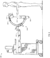
- the imaging device 100 may include a cabinet 105, which may be portable, e.g., on wheels.
- the cabinet 105 may include a power supply, controller, memory, processor, display screen, and/or user interface (not shown) operably connected to each other for operating the imaging device 100.
- An arm assembly 110 may be connected to the cabinet, via an articulating arm 115.
- the arm assembly 110 may include a "C" shaped arm 120, having an x-ray source 125 disposed at one end of the "C" arc and an x-ray detector 130 disposed at the opposite end.
- a space 135 between the x-ray source 125 and the x-ray detector 130 is large enough to receive at least a portion of a patient for imaging, e.g., an arm, a hand, a leg, a foot, a torso, or a combination thereof. It should be understood that the use of "patient” throughout this description may include an extremity or part of an extremity of a patient.
- a "C" shaped arm do not necessarily conform to the exact shape of a "C” and include any configuration that includes the arc of a circle, a portion of an oval, or other curvature(s) or angled portions that result in an x-ray source being positioned opposite from (and at a distance from) an x-ray detector.
- the arm assembly 110 may be rotatable relative to the cabinet 105 and/or the articulating arm 115, the arm assembly 110 is fixed. For example, the position of the x-ray source 125 relative to the x-ray detector 130 with respect to the arm 120 is fixed.
- the arm assembly 110 may be positioned relative to a patient for scanning. When the scanning is completed, the entire arm assembly 110 must be moved away from the patient so a medical professional may access the scanned limb. Often, the arm assembly 110 must subsequently be moved back to the patient for additional scanning. For example, a medical professional may image a patient's limb prior to an operation. They may then perform surgery, for example, implanting screws, plates, and/or rods. Once the implant is complete, another image is taken to ensure proper placement of the implant. As described above, adjusting the arm assembly 110 multiple times for a single procedure is time consuming, and may introduce error in that the positioning may not be repeatable with respect to the patient. This results in images that are not entirely identical.
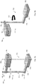
- FIG. 2A illustrates an arm assembly 200, including an x-ray source 205 coupled at an end 245 of an arm 215, and an x-ray detector 210 coupled at an opposite end 245 of the arm 215.
- the arm 215 may include a curvature, for example, in a general "C" shape, so that the x-ray source 205 and the x-ray detector 210 are aligned along an imaging axis 220 when disposed at the ends 245 of the arm 215.
- a space 225 may be created between the x-ray source 205 and the x-ray detector 210 by the alignment of the x-ray source 205 and the x-ray 210.
- a patient may be positioned within the space 225 so that an image may be taken.
- access to the space 225 may be limited.
- a patient may be positioned in the space 225, but a surgical procedure cannot occur without moving at least one of the patient, the x-ray source 205, and/or the x-ray detector 210.
- the arm 215 may be retractable; for example, a first portion 215a may be slidable within a second portion 215b. As shown in FIG. 2B , the first portion 215a is positioned within the second portion 215b, showing a retracted arm 215'. The first portion 215a may be dimensioned smaller than the second portion 215b. The second portion 215b may be generally hollow in order to receive the first portion 215a. In an embodiment, the first portion 215a may be slidable along a second portion 215b. For example, the first portion 215a is repositioned along an exterior surface 250 of the arm 215. As shown in FIGS.
- the first portion 215a is slidable along the second portion 215b, so that the x-ray source 205 is repositioned relative to the x-ray detector 210 in a similar manner as in FIGS. 2A-2B , described in detail below.
- the position of the x-ray source 205 relative to the x-ray detector 210 is altered.
- This is advantageous over existing arm assemblies for imaging devices in that one end 245 of the arm 215 may remain stationary while the other end 245 of the arm 215 is repositioned.
- a patient may be positioned relative to the x-ray detector 210 in the space 225 for imaging prior to a surgical procedure.
- the x-ray source 205 may be re-positioned by retracting the first portion 215a of the arm 215 into the second portion 215b.
- the x-ray detector 210 remains stationary relative to the patient.
- the x-ray detector 210 is repositioned while the x-ray source 205 remains stationary relative to the patient. Regardless of whether one or both of the x-ray source 205 and the x-ray detector are repositioned relative to each other, they may be brought out of alignment with each other along imaging axis 220 to provide access to the space 225.
- a medical professional has greater access to the patient in the space 225, e.g., to conduct the surgical procedure.
- the arm 215 may be adjusted to the original position, e.g., the first portion 215a is extended out of the second portion 215b.
- one of the x-ray source 205 or the x-ray detector 210 may be attachable to a table 230, as shown in FIGS. 2E-2G .
- the x-ray detector 210 is attachable to the table 230.
- the x-ray detector 210 when attached to the table 230, may form a portion of the table 230.
- a cut-out 235 may be configured to receive the x-ray detector 210.
- Projections 240 may extend from the table 230, forming the cut-out 235, to attach and retain the x-ray detector 210.
- the projections 240 may form a shelf in the cut-out 235 for the x-ray source 205 and/or the x-ray detector 210 to slide into position with the table 230.
- a patient may be positioned on the table 230 and the x-ray detector 210.
- the arm 215 may be positioned by sliding the x-ray detector 210 within the projections 240.
- the x-ray source 205 is thereby positioned relative to the patient on the table 230 and the x-ray detector 210, in the space 225.
- Including the x-ray detector 210 as a portion of the table 230 as shown in FIGS. 2E-2G is advantageous in facilitating ease of use of the imaging device in an operating room. For example, patient movement may be minimized for an entire medical procedure in that the combined table 230 and x-ray detector 210 is capable of imaging a patient as well as providing an operating surface. Time needed for the procedure is thereby reduced by eliminating unnecessary patient movement during the medical procedure.
- the x-ray detector 210 may be attachable beneath a surface of the table 230, for example, shown in FIGS. 3E-3H and FIGS. 4C-4E and described below. Attaching the x-ray detector 210 beneath a surface of the table 230 is advantageous in that the x-ray detector is substantially protected from fluids and/or blood during the medical procedure, which would otherwise require cleaning and sterilizing.
- the table 230 may be made of a material that is substantially radiolucent so that x-rays pass through the table between the x-ray source 205 and the x-ray detector 210.
- the x-ray source 205 and/or the x-ray detector 210 may be removably attachable to any portion of the table by a joining mechanism to be easily secured, adjusted, and/or removed from the table, including by not limited to slides, pins, connectors, magnets, and the like.
- an arm assembly 300 is shown.
- an x-ray source 305 and an x-ray detector 310 are coupled to opposite ends 350 of an arm 315.
- the arm 315 may include a first portion 315a, a second portion 315b, and a third portion 315c.
- the first and third portions 315a, 315c may be parallel to each other and extend orthogonally from the second portion 315b.
- the arm includes at least two angles being substantially 90°, generally forming a "C" or "U" shape by the first portion 315a, the second portion 315b, and the third portion 315c.
- the x-ray source 305 and the x-ray detector 310 may be aligned along an imaging axis 320.
- At least one of the portions 315a, 315b, 315c are retractable.
- a first part 315a' of the first portion 315a may be retractable within a second part 315a" of the first portion 315a.
- the x-ray source 305 may be repositioned relative to the x-ray detector 310.
- the first part 315a' of the first portion 315a is retracted within the second part 315a" of the first portion 315a, so that the retracted arm 315' includes the x-ray source 305 out of alignment with the x-ray detector 310.
- a space 325 may be created between the x-ray source 305 and the x-ray detector 310.
- a patient may be positioned within the space 325 so that an image may be taken.
- the retractable portions 315a, 315b, and/or 315c allow for the x-ray source 305 and/or the x-ray detector 310 to be movable as desired.
- a plurality of the portions 315a, 315b, 315c are retractable, so that the patient may remain stationary.
- both the first portion 315a and the third portion 315c are retractable.
- first part 315a' of the first portion 315a is retractable within the second part 315a" of the first portion 315a.
- a first part 315c' of the third portion 315c is retractable within the second part 315c" of the third portion 315c.
- the first part 315a', 315c' may be dimensioned smaller than the second part 315a", 315c".
- the second part 315a", 315c" may be hollow in order to receive the first part 315a', 315c'.
- the position of the x-ray source 305 relative to the x-ray detector 310 may be altered. Regardless of whether one or both of the x-ray source 305 and the x-ray detector 310 are repositioned relative to each other, they may be brought out of alignment with each other along imaging axis 320 to provide access to the space 325. For example, a patient may be positioned relative to the x-ray detector 310 in the space 325 for imaging prior to a surgical procedure. Once the imaging is complete, the x-ray source 305 may be re-positioned by retracting the first part 315a', 315c' of the arm 315 into the second part 315a", 315c".
- the x-ray detector 310 remains stationary relative to the patient.
- the x-ray detector 310 is repositioned while the x-ray source 305 remains stationary relative to the patient. This provides access to the patient in the space 325 by a medical professional, e.g., to conduct the surgical procedure.
- the arm 315 may be adjusted to the original position, e.g., the first part 315a', 315c' is extended out of the second part 315a", 315c".
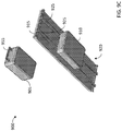
- one of the x-ray source 305 or the x-ray detector 310 may be attachable to a table 330, as shown in FIGS. 3E-3H .
- the x-ray detector is attachable to the table 330.
- the x-ray detector 310 may be attachable to a bottom surface 335 of the table 330.
- tracks 340 may be configured to receive the x-ray detector 310, so that the x-ray detector 310 is attachable and retainable to the table 330, as shown in FIGS. 3G and 3H .
- the tracks 340 may be a projection extending from the bottom surface 335 of the table 330, so that a portion 345 of the x-ray detector 310 may be configured to connect to the tracks 340.
- the connection may be a tongue and groove and/or a T-shaped slot and projection.
- FIG. 3G shows a portion 345 of the x-ray detector 310 when the x-ray detector is removed from the table 330.
- FIG. 3H shows that the portion 345 of the x-ray detector 310 is received in the tracks 340, so that the x-ray detector 310 is attached and retained to the table 330.
- the x-ray detector 310 or x-ray source 305 may be attachable to form at least a part of the table surface, for example, shown in FIGS. 2E-2G described below.
- FIG. 4A illustrates an arm assembly 400, including an x-ray source 405 coupled at an end 450 of an arm 415, and an x-ray detector 410 coupled at an opposite end 450 of the arm 415.
- the arm 415 may include a curvature, for example, generally in a "C" shape, so that the x-ray source 405 and the x-ray detector 410 are aligned along an imaging axis 420 when disposed at the ends 450 of the arm 415.
- a space 425 may be created between the x-ray source 405 and the x-ray detector 410.
- a patient may be positioned within the space 425 so that an image may be taken.
- access to the space 425 may be limited.
- a patient may be positioned in the space 425, but any surgical procedure cannot occur without moving at least one of the patient, the x-ray source 405, and/or the x-ray detector 410.
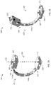
- the arm 415 may include a hinge 430 so that the x-ray source 405 and/or the x-ray detector are movable as desired.
- the hinge 430 may be disposed along the curvature of the arm 415, so that the arm 415 includes a first portion 415a and a second portion 415b. In an embodiment, the hinge 430 may be disposed at a midpoint of the curvature of the arm 415, so that the first portion 415a is equal to the second portion 415b.
- the hinge 430 allows an x-ray source 405 coupled to a first portion 415a to be hingedly rotated with respect to the x-ray detector 410 coupled to the second portion 415b.
- the x-ray detector 410 coupled to the second portion 415b may be hingedly rotated with respect to the x-ray source 405 coupled to the first portion 415a.
- the hinge 430 may be disposed anywhere along the arm 415, e.g., the end 450, so that the x-ray source 405 and/or the x-ray detector 410 are hingedly coupled to the arm 415.
- the hinge 430 disposed at an end 450 of the arm 415 allows an x-ray source 405 and/or the x-ray detector 410 to be hingedly rotated with respect to the arm 415 about an axis 435.
- the hinge 430 results in the first portion 415a opening with respect to the second portion 415b, although the hinge may be disposed in any alignment to allow one of the first portion 415a and the second portion 415b to be rotated with respect to the other of the first portion 415a and the second portion 415b for accessing the space 425.
- the hinge 430 rotates the first portion 415a about the axis 435
- the rotated arm 415' alters the position of the x-ray source 405 with respect to the x-ray detector 410, so that the rotated arm 415' includes the x-ray source 405 out of alignment with the x-ray detector 410.
- the x-ray source 405 and the x-ray detector 410 may be brought out of alignment with each other along imaging axis 420 to provide access to the space 425
- the position of the x-ray source 405 relative to the x-ray detector 410 is altered.
- This is advantageous over existing arm assemblies for imaging devices in that one end 450 of the arm 415 may remain stationary while the other end 450 of the arm 415 is repositioned.
- a patient may be positioned relative to the x-ray detector 410 in the space 425 for imaging prior to a surgical procedure.
- the x-ray source 405 may be re-positioned by rotating the first portion 415a of the arm 415 relative to the second portion 415b about the hinge 430.
- the x-ray detector 410 remains stationary relative to the patient.
- the x-ray detector 410 is repositioned while the x-ray source 405 remains stationary relative to the patient. This provides access to the patient in the space 425 by a medical professional, e.g., to conduct the surgical procedure.
- the arm 415 may be adjusted to the original position, e.g., the first portion 415a is rotated back via the hinge 430 relative to the second portion 415b.
- the hinge 430 may couple the x-ray detector 410 to an end 450 of the arm 415, while the x-ray source 405 is fixedly coupled to the arm 415, as shown in FIGS. 4C-4E . It is also envisioned that in an embodiment the x-ray source 405 may be hingedly coupled to the arm 415 and the x-ray detector 410 is fixedly coupled to the arm 415. The x-ray detector 410 may remain stationary while the x-ray source 405 and the entire arm 415 rotates with respect to the x-ray detector 410.
- the x-ray detector 410 may be attachable to a table 460.
- the x-ray detector may be slidable along a bottom surface 440.
- the table may include projections 445 to receive and retain the x-ray detector 410, as described above with respect to FIGS. 3E-3H .
- the x-ray detector 410 may form a portion of the table, as shown in FIGS. 2E-2G and described in detail above.
- the x-ray detector 410 and the x-ray source 405 may be positioned relative to the patient on the table 460, in the space 425.
- FIG. 5A illustrates an arm assembly 500, including an x-ray source 505 coupled at an end 540 of an arm 515, and an x-ray detector 510 coupled at an opposite end 540 of the arm 515.
- the arm 515 may include a curvature, for example, in a general "C" shape, so that the x-ray source 505 and the x-ray detector 510 are aligned along an imaging axis 520 when disposed at the ends 540 of the arm 515.
- a space 525 may be created between the x-ray source 505 and the x-ray detector 510 by the alignment of the x-ray source 505 and the x-ray detector 510.
- a patient may be positioned within the space 525 so that an image may be taken. However, when the x-ray source 505 and the x-ray detector 510 are aligned, access to the space 525 may be limited.
- a patient may be positioned in the space 525, but a surgical procedure cannot occur without moving at least one of the patient, the x-ray source 505, and/or the x-ray detector 510.
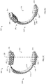
- the arm 515 may include a pivot point 530 so that the x-ray source 405 and/or the x-ray detector are movable as desired.
- the pivot point 530 may be disposed along the curvature of the arm 515, so that the arm 515 is divided into a first portion 515a and a second portion 515b.
- the pivot point 530 may be disposed at a midpoint of the curvature of the arm 515, so that the first portion 515a is equal in length to the second portion 515b.
- the pivot point 530 may be disposed anywhere along the arm 515.
- the pivot point 530 allows an x-ray source 505 coupled to a first portion 515a to be pivotably rotatable with respect to the x-ray detector 510 coupled to the second portion 515b.
- the x-ray detector 510 coupled to the second portion 515b may be pivotably rotatable with respect to the x-ray source 505 coupled to the first portion 515a.
- the pivot point 530 may be any mechanical joining of the first portion 515a and the second portion 515b of the arm 515 to be rotatable relative to each other.
- one of the first or second portions 515a, 515b may include a dowel, or protrusion (not shown) to be received in an aperture of the other of the first or second portion 515a, 515b.
- the pivot point 530 may allow one of the first or second portion 515a, 515b to rotate in a direction indicated by arrow 535 so that rotated arm 515' includes the x-ray source 505 out of alignment with the x-ray detector 510.
- the general "C" shape shown in FIG. 5A may become generally an "S" shape shown in FIG. 5B .
- one of the first or second portion 515a, 515b may be fully rotatable, 360° around in the direction indicated by arrow 535.
- the position of the x-ray source 505 relative to the x-ray detector 510 is altered.
- This is advantageous over existing arm assemblies for imaging devices in that one end 540 of the arm 515 may remain stationary while the other end 540 of the arm 515 is repositioned.
- a patient may be positioned relative to the x-ray detector 510 in the space 525 for imaging prior to a surgical procedure.
- the x-ray source 505 may be re-positioned by rotating the first portion 515a of the arm 515 relative to the second portion 515b about the pivot point 530.
- the x-ray detector 510 may remain stationary relative to the patient.
- the x-ray detector 510 is repositioned while the x-ray source 505 remains stationary relative to the patient. Regardless of whether one or both of the x-ray source 505 and the x-ray detector 510 are repositioned relative to each other, they may be brought out of alignment with each other along imaging axis 520 to provide access to the space 525. Upon completion of the procedure, the arm 515 may be adjusted to the original position, e.g., the first portion 515a is rotated back relative to the second portion 515b.
- FIG. 6A illustrates an arm assembly 600, including an x-ray source 605 coupled at an end 635 of an arm 615, and an x-ray detector 610 coupled at an opposite end 635 of the arm 615.
- the arm 615 may include a curvature, for example, in generally a "C" or "U” shape, so that the x-ray source 605 and the x-ray detector 610 are aligned along an imaging axis 620 when disposed at the ends of the arm 615.
- a space 625 may be created between the x-ray source 605 and the x-ray detector 610 by the alignment of the x-ray source 605 and the x-ray 610.
- a patient may be positioned within the space 625 so that an image may be taken.
- access to the space 625 may be limited.
- a patient may be positioned in the space 625, but a surgical procedure cannot occur without moving at least one of the patient, the x-ray source 605, and/or the x-ray detector 610.
- the arm 615 may include a telescoping portion 630.
- a telescoping portion 630 may include a plurality of nesting slides 630a, 630b, ... 630n configured to retract within at least a portion of the arm 615.
- the arm 615 may include a telescoping portion at an end 635 of the arm 615, thereby connecting one of the x-ray source 605 and the x-ray detector 610 to the telescoping portion 630.
- the nesting slides 630a, 630b, ... 630n may be sized to nest within each other when in a retracted state, and further retracting within the arm 615.
- the arm 615 may be hollow to receive the nesting slides 630a, 630b, ... 630n.
- FIG. 6B shows the arm 615' retracted, so that the nesting slides 630a, 630b, .... 630n are not visible.
- retracted arm 615' includes the x-ray source 605 out of alignment with the x-ray detector 610.
- the arm 615 may include a curvature.
- the arm 615 may include a curvature portion 615a and one or more straight portions 615b.
- the straight portions 615b may be at ends 635 of the arm 615, so that the telescoping portion 630 may extend from the straight portion 615b.
- the x-ray source 605 when the telescoping portion 630 is extended, the x-ray source 605 is aligned with the x-ray detector 610 along imaging axis 620.
- the position of the x-ray source 205 relative to the x-ray detector 210 is altered as shown in FIG. 6B .
- a patient may be positioned relative to the x-ray detector 610 in the space 625 for imaging prior to a surgical procedure.
- the x-ray source 605 may be re-positioned by retracting telescoping portion 630 into the arm 615.
- the x-ray detector 610 remains stationary relative to the patient.
- the x-ray detector 610 is repositioned while the x-ray source 605 remains stationary relative to the patient. This provides access to the patient in the space 625 by a medical professional, e.g., to conduct the surgical procedure.
- the arm 615 may be adjusted to the original position, e.g., the telescoping portion 630 is extended so that the x-ray source 605 and the x-ray detector 610 are aligned along the imaging axis 620.
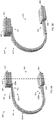
- FIG. 7A illustrates an arm assembly 700, including an x-ray source 705 coupled at an end 740, 745 of an arm 715, and an x-ray detector 710 coupled at an opposite end 740,745 of the arm 715.
- the arm 715 may be a single piece, cylindrical tube.
- the x-ray source 705 may be rotatably attachable to the arm 715 via a connecting end 730 extending from the x-ray source 705, and the x-ray detector 710 may be rotatably attachable to the arm 715 via a connecting end 735 extending form the x-ray detector 710.
- the connecting end 730 of the x-ray source 705 may be rotatably attached to a first end 740 of the arm 715, and the connecting end 735 may be rotatably attached to a second end 745 opposite the first end 740 of the arm 715.
- the connecting ends 730, 735 may be attachable orthogonal to the arm 715, and parallel to each other.
- the connecting ends 730, 735 may include an aperture 750, 755, respectively, to receive the arm 715.
- the x-ray source 705 and the x-ray detector 710 may be aligned along an imaging axis 720, so that the arm assembly 700 forms generally a "C" or "U" shape.
- a space 725 may be created between the x-ray source 705 and the x-ray detector 710 by the alignment of the x-ray source 705 and the x-ray 710.
- a patient may be positioned within the space 725 so that an image may be taken.
- access to the space 725 may be limited.
- a patient may be positioned in the space 725, but a surgical procedure cannot occur without moving at least one of the patient, the x-ray source 705, and/or the x-ray detector 710.
- the connecting ends 730, 735 may be rotatable about the arm 715, thereby moving the x-ray source 705 and/or the x-ray detector 710 as desired.
- the x-ray source 705 may be aligned with the x-ray detector 710 along imaging axis 720 by rotating the connecting ends 730, 735.
- One of the x-ray source 705 or the x-ray detector 710 may be re-positioned by rotating the connecting end 730, 735 about the arm 715.
- the connecting ends 730, 735 may be rotatable in a direction indicated by arrow 760.
- the general "C" or "U" shape shown in FIG. 7A may become generally an "S" shape shown in FIG. 7B so that rotated arm 715' includes the x-ray source 705 out of alignment with the x-ray detector 710.
- a patient may be positioned relative to the x-ray detector 710 in the space 725 for imaging prior to a surgical procedure.
- the x-ray source 705 may be re-positioned rotating the x-ray source 705 via the connecting end 730 about the arm 715.
- the x-ray detector 710 remains stationary relative to the patient and the arm 715.
- the x-ray detector 710 is repositioned while the x-ray source 705 remains stationary relative to the patient. This provides access to the patient in the space 725 by a medical professional, e.g., to conduct the surgical procedure.
- x-ray source 705 may be adjusted back to its original position, e.g., the connecting end 730 is rotated about the arm 715 so that the x-ray source 705 and the x-ray detector 710 are aligned along the imaging axis 720.
- the connecting ends 730, 735 may be fixedly attached to the arm 715.
- the arm 715 may include a first portion 715a and a second portion 715b, rotatable relative to each other.
- a first portion 715a of the arm 715 may be rotatable relative to the second portion 715b of the arm 715, so that the x-ray source 705, connecting end 730, and first portion 715a of the arm 715 are rotated in a direction indicated by arrow 760, while the x-ray detector 710, connecting end 735, and second portion 715b of the arm 715 remain stationary.
- one of the first or second portions 715a, 715b may be rotatable relative to the other in a direction indicated by arrow 760 in 360°.
- FIG. 8A illustrates an arm assembly 800, including an x-ray source 805 coupled at an end 835, 840 of an arm 815, and an x-ray detector 810 coupled at an opposite end 835, 840 of the arm 815.
- the arm 815 may include a curvature, for example, in a general "C" shape, so that the x-ray source 805 and the x-ray detector 810 are aligned along an imaging axis 820 when disposed at the ends 835, 840 of the arm 815.
- the x-ray source 805 may be disposed at a first end 835 of the arm 815, and the x-ray detector may be disposed at a second end 840 of the arm 815.
- a space 825 may be created between the x-ray source 805 and the x-ray detector 810 by the alignment of the x-ray source 805 and the x-ray 810.
- a patient may be positioned within the space 825 so that an image may be taken.
- access to the space 825 may be limited.
- a patient may be positioned in the space 825, but a surgical procedure cannot occur without moving at least one of the patient, the x-ray source 805, and/or the x-ray detector 810.
- At least one of the x-ray source 805 and/or the x-ray detector 810 may be slidable along the arm 815.
- the x-ray source 805 is adjustable along the curvature of the arm 815.
- x-ray source 805 is repositioned along a surface 830 of the arm 815.
- the x-ray source 805 and/or the x-ray detector 810 may be slidable along an inner surface of the arm 815, although it is envisioned that the x-ray source 805 and/or the x-ray detector 810 may be slidable along an outer surface of the arm 815.
- the x-ray source 805 and/or the x-ray detector 810 may be shaped to match the curvature of the arm 815.
- a portion 845 of the x-ray source 805 may include a curvature.
- the curvature may be substantially the same as the curvature of the arm 815.
- the curvature may be concave or convex, relative to the positioning of the x-ray source 805 and/or the x-ray detector 810.
- the curvature of portion 845 of x-ray source 805 is convex being disposed on an inner surface of the arm 815.
- the x-ray source 805 and/or the x-ray detector 810 may be disposed on an outer surface of the arm 815, such that a curvature of a portion 845 of the x-ray source 805 may be concave.
- the arm 815 may have a track
- the x-ray source 805 and/or the x-ray detector 810 may include means for attaching to the track of the arm 815.
- the means for attaching may include but not be limited to projections, a tongue and groove configuration, and other joining mechanisms for a slidable attachment.
- the x-ray source 805 and/or the x-ray detector 810 may be attached to other areas of the arm 815 as well, including but not limited to a wrap-around sliding mechanism extending from a side 850 of the arm 815 instead of the surface 830 of the arm 815.
- the position of the x-ray source 805 relative to the x-ray detector 810 is altered.
- a patient may be positioned relative to the x-ray detector 810 in the space 825 for imaging prior to a surgical procedure.
- the x-ray source 805 may be re-positioned by sliding the x-ray source 805 along the exterior surface 830 of the arm 815.
- the x-ray detector 810 may remain stationary relative to the patient.
- the x-ray detector 810 is repositioned while the x-ray source 805 remains stationary relative to the patient.
- the x-ray source 805 may be adjusted to the original position, e.g., the x-ray source 805 is extended to the first end 835 of the arm 815 so that the x-ray source 805 is aligned with the x-ray detector 810 along the imaging axis 820.
- the arm may be made of a material strong enough to maintain stability of the x-ray source and the x-ray detector, but light enough that a user may easily position the arm.
- the arm may be made of a metal or metal alloy, such as aluminum, or a plastic or composite material.
- connecting cables (not shown) connecting the x-ray source to the x-ray detector may be disposed within the arm.
- the arm may be dimensioned so that the hollow area in the second portion may receive excess length of the connecting cable when the first portion is retracted into the second portion.
- the connecting cables may be exterior to the arm.
- the cables may alternatively or additionally be movable to accommodate the rotation of the first portion and/or the second portion.
- the cables may be movable to accommodate movement of the arm to eliminate pinch points and enhance patient and user safety.
- counterweights may be needed for the embodiments described with respect to FIGS. 2A-8B , to balance the retracted and/or rotated arm when in a repositioned state, as the center of gravity of the respective arm is shifted.
- an assembly 900 is shown.
- an x-ray source 905 and an x-ray detector 910 may be independent of each other, with no arm connecting each other.
- One of the x-ray source 905 and the x-ray detector 910 may be coupled to a table 915. Similar to the embodiment described with respect to FIGS. 3E-3H and 4C-4E , one of the x-ray source 905 and the x-ray detector 910 may be slidably attached to a bottom surface 920 of the table 915.
- Projections 925 may extend from the bottom surface 920 of the table 915, and may be configured to attach and retain the x-ray source 905 or the x-ray detector 910.
- the x-ray source 905 and the x-ray detector 910 may be aligned along an imaging axis 930 for imaging a patient.
- the patient may be positioned on a top surface 935 of the table 915, in a space 940 created between the x-ray source 905 and the x-ray detector 910.
- the x-ray source 905 may be re-positioned in an area away from the x-ray detector 910.
- the x-ray source 905 may be connected to a cable or boom on a ceiling (not shown), which may be raised and/or lowered as desired.
- the x-ray source 905 may be removably attachable to other equipment in an operating room.
- the x-ray detector 910 may be slidable along projections 925 on the bottom surface 920 of the table 915.
- the x-ray detector 905 and the x-ray detector 910 When at least one of the x-ray detector 905 and the x-ray detector 910 are re-positioned, medical professionals may access the space 940 to perform surgical procedures on the patient. The patient therefore may remain stationary while the x-ray source 905 and/or the x-ray detector 910 are repositioned. When the surgical procedure is complete, if another image is necessary, the x-ray source 905 and/or the x-ray detector 910 may be positioned back into their original positions, e.g., the x-ray source 905 and the x-ray detector 910 are aligned along imaging axis 930.
- the imaging device may further include a controller disposed within a cabinet, the controller being operably connected to the arm, x-ray source, and/or the x-ray detector for automatic positioning.
- the arm may be directly attached to the cabinet, although the arm may optionally also be attached to intermediate assemblies.
- the controller may send control signals for positioning the x-ray source and the x-ray detector relative to each other.
- the x-ray source may be directed automatically to the desired position pre-programmed into a memory of the controller. Storing the desired positions in the memory of the controller may also provide greater repeatability and decrease usage time for imaging.
- a user may, optionally, also enter in the desired position to direct the imaging device components (e.g., the x-ray source, the x-ray detector, arm) via a user interface operably connected to the controller.
- the user interface may be means for entering data and operably connected to the controller such as a computer, keyboard, mouse, touchscreen, tablet, mobile phone, and the like.
- the user interface may include a microphone and voice activation software controls configured to receive oral commands of the user and position the imaging device as desired.
- the user interface may additionally include a hands-free operable switch, including but not limited to a foot pedal or switch, operably connected to the controller so that the user may position the components of the imaging device in a hands free manner.
- the hands-free switch may be independent of the device, so that a user may access the switch e.g., during a surgical procedure.
- imaging may be disabled to ensure safety of the user and the patient, minimizing potential radiation exposure.
- the controller may detect the alignment of the x-ray source and the x-ray detector and disable their operation until properly aligned. As operating rooms and other medical procedure rooms have limited space available, and often multiple people moving about the area, automatically disabling the x-ray source and the x-ray detector may prevent accidentally initializing operation. This may also improve the quality and repeatability of imaging, as imaging will only occur when the x-ray source and the x-ray detector are properly aligned.
- the x-ray source, the x-ray detector, and/or the arm may be manually moved and positioned according to the needs of the patient and/or the user.
- the x-ray source and/or the x-ray detector may include a projection, or handle 255, 355, 455, 555, 655, 765, 855, 955.
- the handle may be coupled to the x-ray source and/or the x-ray detector to provide a point of contact for a user for manual repositioning. While the handle may be disposed at an end of the x-ray source and/or x-ray detector, it should be understood that the handle may be disposed on any side to provide ease of access to the user.
- the device may also include sensors (e.g., radio frequency ID (RFID), global positioning system (GPS), optical laser, infrared, etc.) for verifying an alignment of and/or distance between the x-ray source and the x-ray detector.
- RFID radio frequency ID
- GPS global positioning system
- optical laser infrared
- the x-ray source may not be operable unless the x-ray detector is in alignment along its imaging axis to receive x-rays for imaging, to ensure patient and user safety.
- a predetermined source-to-image receptor distance (SID) between the x-ray source and the x-ray detector is required for the imaging device to be operable.
- the space between the x-ray source and the x-ray detector is constant when aligned.
- the imaging devices described in FIGS. 2A-9C may include a mechanical, electro-mechanical, and/or magnetic locking device for locking the x-ray source and/or the x-ray detector in a desired position relative to the device (e.g., arm, operating table).
- the locking device ensures the x-ray source and the x-ray detector remain immobile during an imaging process and/or when adjusted for a surgical procedure to ensure patient and user safety.
- the user may engage and/or disengage the locking device when manually positioning the imaging device.
- the locking device may engage automatically when positioning one of the x-ray source, x-ray detector, and arm to a predetermined position.
- the locking device may automatically engage and/or disengage during automatic movement of the imaging device, for example, by the controller.
- a kill switch, or emergency shut-off may also be provided so that automatic movement of the device may be halted by the user to ensure patient and user safety.
- the locking device and/or kill switch may be able to engage and/or disengage remotely, and in a hands-free manner (e.g., foot pedal, voice-activation) when the user may be performing a medical procedure.
- an x-ray source disposed at a first end of an arm is aligned with an x-ray detector disposed at a second end of the arm opposite the first end of the arm.
- the x-ray source emits x-rays which are receivable by the x-ray detector through a space between the first end of the arm and the second end of the arm.
- a patient may be positioned in the space between the first end of the arm and the second end of the arm, so that the x-ray image captures the desired bone and tissue images.
- At step 1015 at least one of the x-ray source and the x-ray detector are adjusted with respect to the arm. Adjusting the at least one of the x-ray source and the x-ray detector results in the x-ray source and the x-ray detector being out of alignment with each other.
- the space between the first end of the arm and the second end of the arm is accessed.
- a surgical procedure may be performed on a patient in the area that was imaged.
- the x-ray source and the x-ray detector may be re-aligned with each other, so that another image may be taken.
- a follow-up image after completion of a surgical procedure may verify correct bone settings and/or placement of implants.
- the invention relates to any medical imaging device for extremity imaging in which an imaging source is spaced apart from and facing an imaging receptor.
- An example of such an arrangement include x-ray devices including a C-arm.
- the invention herein can also be applied to any x-ray medical imaging device, such as 2D x-ray technology, tomosynthesis, computed tomography, and/or combinations thereof. Examples of such systems include U.S. Patent Nos. 7,123,684 ; 7,577,282 ; 7,831,296 ; 8,175,219 ; 8,565,374 ; and 8,787,522 , and U.S. Patent Application Publication No. 2016/0256125 .
- Some embodiments of the disclosed device may be implemented, for example, using a storage medium, a computer-readable medium or an article of manufacture which may store an instruction or a set of instructions that, if executed by a machine (i.e., processor or microcontroller), may cause the machine to perform a method and/or operations in accordance with embodiments of the disclosure.
- a server or database server may include machine readable media configured to store machine executable program instructions.
- Such a machine may include, for example, any suitable processing platform, computing platform, computing device, processing device, computing system, processing system, computer, processor, or the like, and may be implemented using any suitable combination of hardware, software, firmware, or a combination thereof and utilized in systems, subsystems, components, or sub-components thereof.
- the computer-readable medium or article may include, for example, any suitable type of memory unit, memory device, memory article, memory medium, storage device, storage article, storage medium and/or storage unit, for example, memory (including non-transitory memory), removable or non-removable media, erasable or non-erasable media, writeable or rewriteable media, digital or analog media, hard disk, floppy disk, Compact Disk Read Only Memory (CD-ROM), Compact Disk Recordable (CD-R), Compact Disk Rewriteable (CD-RW), optical disk, magnetic media, magneto-optical media, removable memory cards or disks, various types of Digital Versatile Disk (DVD), a tape, a cassette, or the like.
- memory including non-transitory memory
- removable or non-removable media erasable or non-erasable media, writeable or rewriteable media, digital or analog media
- hard disk floppy disk
- CD-ROM Compact Disk Read Only Memory
- CD-R Compact Disk Recordable
- the instructions may include any suitable type of code, such as source code, compiled code, interpreted code, executable code, static code, dynamic code, encrypted code, and the like, implemented using any suitable high-level, low-level, object-oriented, visual, compiled and/or interpreted programming language.
Landscapes
- Health & Medical Sciences (AREA)
- Life Sciences & Earth Sciences (AREA)
- Engineering & Computer Science (AREA)
- Medical Informatics (AREA)
- Radiology & Medical Imaging (AREA)
- Molecular Biology (AREA)
- Biophysics (AREA)
- Nuclear Medicine, Radiotherapy & Molecular Imaging (AREA)
- Optics & Photonics (AREA)
- Pathology (AREA)
- Physics & Mathematics (AREA)
- Biomedical Technology (AREA)
- Heart & Thoracic Surgery (AREA)
- High Energy & Nuclear Physics (AREA)
- Surgery (AREA)
- Animal Behavior & Ethology (AREA)
- General Health & Medical Sciences (AREA)
- Public Health (AREA)
- Veterinary Medicine (AREA)
- Human Computer Interaction (AREA)
- Automation & Control Theory (AREA)
- Robotics (AREA)
- Apparatus For Radiation Diagnosis (AREA)
Claims (15)
- Dispositif d'imagerie médicale (100), comprenant :- un bras ;- une source de rayons X (205) disposée à une première extrémité (245) du bras ; et- un détecteur de rayons X (210) disposé à une seconde extrémité (245) du bras ;
dans lequel la source de rayons X et/ou le détecteur de rayons X et/ou une partie du bras sont réglables sélectivement par rapport au bras pour agencer le dispositif d'imagerie médicale soit dans un premier agencement (200), soit dans un second agencement (200'), dans lequel, dans le premier agencement, la source de rayons X et le détecteur de rayons X sont alignés de telle sorte que les rayons X émis par la source de rayons X peuvent être reçus par le détecteur de rayons X à travers un espace (225) entre la première extrémité du bras et la seconde extrémité du bras, caractérisé en ce que
dans le second agencement (200'), la source de rayons X et le détecteur de rayons X ne sont pas alignés l'un par rapport à l'autre de sorte qu'un professionnel de la santé a un meilleur accès à un patient dans l'espace pour effectuer une intervention chirurgicale. - Dispositif selon la revendication 1, dans lequel le bras comporte au moins deux angles, les angles étant sensiblement de 90°, de telle sorte que le bras présente une première partie, une deuxième partie agencée de manière orthogonale par rapport à la première partie, et une troisième partie parallèle à la première partie.
- Dispositif selon la revendication 2, dans lequel la première partie est sensiblement horizontale et accouplée à l'un de la source de rayons X et du détecteur de rayons X, et la troisième partie est sensiblement horizontale et accouplée à l'autre de la source de rayons X et du détecteur de rayons X ; et dans lequel la deuxième partie est sensiblement verticale, les extrémités de la deuxième partie étant accouplées à la première partie et à la troisième partie.
- Dispositif selon l'une quelconque des revendications précédentes, dans lequel la première extrémité du bras et/ou la seconde extrémité du bras sont rétractables, la source de rayons X et/ou le détecteur de rayons X étant accouplés à l'extrémité rétractable du bras.
- Dispositif selon la revendication 4, dans lequel l'extrémité rétractable du bras est réglable le long d'une courbure du bras de telle sorte que la source de rayons X et/ou le détecteur de rayons X sont réglables le long de la courbure du bras.
- Dispositif selon l'une quelconque des revendications 4 à 5, dans lequel l'extrémité rétractable est conçue pour se rétracter dans au moins une partie du bras.
- Dispositif selon l'une quelconque des revendications 4 à 6, dans lequel l'extrémité rétractable est une pluralité de coulisses emboîtées conçues pour se rétracter dans au moins une partie du bras.
- Dispositif selon la revendication 4, dans lequel l'extrémité rétractable est conçue pour coulisser le long d'une partie extérieure d'une courbure du bras.
- Dispositif selon l'une quelconque des revendications précédentes, dans lequel le bras comporte une charnière (430) disposée le long d'une courbure du bras, de telle sorte qu'au moins une partie du bras et la source de rayons X et/ou le détecteur de rayons X peuvent entrer en rotation l'une par rapport aux autres autour de la charnière.
- Dispositif selon la revendication 9, dans lequel la charnière est disposée à un point médian (430) d'une courbure du bras.
- Dispositif selon l'une quelconque des revendications précédentes, dans lequel le bras comporte un point d'articulation disposé le long d'une courbure du bras, de telle sorte qu'au moins une partie du bras et la source de rayons X et/ou le détecteur de rayons X peuvent pivoter l'une par rapport aux autres.
- Dispositif selon la revendication 11, dans lequel le point d'articulation est disposé à un point médian (430) d'une courbure du bras.
- Dispositif selon l'une quelconque des revendications précédentes, dans lequel la source de rayons X et/ou le détecteur de rayons X sont accouplés de manière coulissante au bras de telle sorte que la source de rayons X et/ou le détecteur de rayons X sont peuvent être positionnés le long d'une courbure du bras.
- Dispositif selon l'une quelconque des revendications précédentes 1, dans lequel la source de rayons X et/ou le détecteur de rayons X peuvent être fixés à une table.
- Dispositif selon la revendication 1, dans lequel la source de rayons X est reliée de manière rotative à la première extrémité du bras.
Applications Claiming Priority (2)
| Application Number | Priority Date | Filing Date | Title |
|---|---|---|---|
| US201662417588P | 2016-11-04 | 2016-11-04 | |
| PCT/US2017/059807 WO2018085602A1 (fr) | 2016-11-04 | 2017-11-02 | Dispositif d'imagerie médicale et procédé de fonctionnement d'un dispositif d'imagerie médicale |
Publications (2)
| Publication Number | Publication Date |
|---|---|
| EP3534795A1 EP3534795A1 (fr) | 2019-09-11 |
| EP3534795B1 true EP3534795B1 (fr) | 2021-01-13 |
Family
ID=60321027
Family Applications (1)
| Application Number | Title | Priority Date | Filing Date |
|---|---|---|---|
| EP17797839.2A Active EP3534795B1 (fr) | 2016-11-04 | 2017-11-02 | Dispositif d'imagerie médicale |
Country Status (5)
| Country | Link |
|---|---|
| US (3) | US11147525B2 (fr) |
| EP (1) | EP3534795B1 (fr) |
| CN (1) | CN110121299A (fr) |
| ES (1) | ES2858363T3 (fr) |
| WO (1) | WO2018085602A1 (fr) |
Families Citing this family (5)
| Publication number | Priority date | Publication date | Assignee | Title |
|---|---|---|---|---|
| EP3534795B1 (fr) * | 2016-11-04 | 2021-01-13 | Hologic, Inc. | Dispositif d'imagerie médicale |
| CN106680865B (zh) * | 2017-03-08 | 2018-11-06 | 沈阳东软医疗系统有限公司 | 一种射线源组件的漏射线测试方法及设备 |
| US11109826B2 (en) * | 2018-12-19 | 2021-09-07 | Onyx Technical Consulting, Llc | Fluoroscopy system with movable imaging head/X-ray detector |
| US11412999B2 (en) * | 2019-11-20 | 2022-08-16 | GE Precision Healthcare LLC | Methods and systems for a medical imaging system with C-arm |
| US20230218251A1 (en) * | 2020-06-10 | 2023-07-13 | Hologic, Inc. | Mini c-arm with movable source |
Family Cites Families (77)
| Publication number | Priority date | Publication date | Assignee | Title |
|---|---|---|---|---|
| JPH0524005U (ja) * | 1991-09-17 | 1993-03-30 | 株式会社日立製作所 | Mrイメージング装置 |
| DE19533716A1 (de) * | 1995-09-12 | 1997-03-13 | Siemens Ag | Röntgendiagnostikeinrichtung mit einer Positioniervorrichtung für einen Strahlensender und einen Strahlenempfänger |
| GB2332562B (en) * | 1997-12-18 | 2000-01-12 | Simage Oy | Hybrid semiconductor imaging device |
| DE19827022C2 (de) * | 1998-06-17 | 2002-01-03 | Siemens Ag | Medizinisches Gerät |
| JP2000116631A (ja) * | 1998-10-16 | 2000-04-25 | Toshiba Corp | X線診断装置 |
| JP4417459B2 (ja) * | 1999-01-11 | 2010-02-17 | 株式会社東芝 | X線診断装置 |
| JP4398528B2 (ja) * | 1999-02-12 | 2010-01-13 | 株式会社東芝 | 放射線診断装置 |
| US6282264B1 (en) * | 1999-10-06 | 2001-08-28 | Hologic, Inc. | Digital flat panel x-ray detector positioning in diagnostic radiology |
| DE19958864A1 (de) * | 1999-12-07 | 2001-06-13 | Philips Corp Intellectual Pty | Röntgeneinrichtung |
| DE10008053A1 (de) * | 2000-02-22 | 2001-09-06 | Siemens Ag | Röntgeneinrichtung und medizinischer Arbeitsplatz für die Diagnostik und für chirurgische Eingriffe im Kopf - und Kiefernbereich eines Patienten |
| US6619840B2 (en) * | 2001-10-15 | 2003-09-16 | Koninklijke Philips Electronics N.V. | Interventional volume scanner |
| DE10161322B4 (de) * | 2001-12-13 | 2009-04-02 | Siemens Ag | Röntgeneinrichtung |
| EP1474040B1 (fr) * | 2002-02-15 | 2007-10-24 | Breakaway Imaging, Llc | Portique circulaire a segment amovible pour imagerie a rayons x multidimensionnelle |
| JP2005527800A (ja) * | 2002-03-19 | 2005-09-15 | ブレークアウェイ・イメージング・エルエルシー | 大視野の対象物を画像化するシステムおよび方法 |
| DE10216857A1 (de) * | 2002-04-16 | 2003-11-13 | Siemens Ag | Verfahren zur Steuerung einer Röntgeneinrichtung |
| US7123684B2 (en) | 2002-11-27 | 2006-10-17 | Hologic, Inc. | Full field mammography with tissue exposure control, tomosynthesis, and dynamic field of view processing |
| US7577282B2 (en) | 2002-11-27 | 2009-08-18 | Hologic, Inc. | Image handling and display in X-ray mammography and tomosynthesis |
| US7831296B2 (en) | 2002-11-27 | 2010-11-09 | Hologic, Inc. | X-ray mammography with tomosynthesis |
| WO2006058160A2 (fr) | 2004-11-26 | 2006-06-01 | Hologic, Inc. | Systeme et procede radiographiques multimode integrant mammographie/tomosynthese |
| WO2005013828A1 (fr) * | 2003-08-07 | 2005-02-17 | Xoran Technologies, Inc. | Systeme d'imagerie peroperatoire |
| DE10352010B3 (de) * | 2003-11-07 | 2005-09-08 | Siemens Ag | Patientenlagerungsvorrichtung mit Positioniervorrichtung |
| US10213171B2 (en) * | 2005-07-08 | 2019-02-26 | Shimadzu Corporation | X-ray photography system |
| EP1926432B1 (fr) * | 2005-09-09 | 2016-04-27 | Koninklijke Philips N.V. | Appareil d'examen aux rayons x |
| DE102005049106A1 (de) * | 2005-10-13 | 2007-04-19 | Siemens Ag | Medizinisches Bildgebungssystem und Kollisionsschutzverfahren mit regelbarem Arm |
| US7300205B2 (en) * | 2005-11-25 | 2007-11-27 | Grady John K | Angio capable portable x-ray fluoroscopy unit with sliding C-arm and variable pivot |
| DE102006004590A1 (de) * | 2006-02-01 | 2007-08-09 | Siemens Ag | Mammografiegerät |
| DE102006028327B3 (de) * | 2006-06-20 | 2008-01-31 | Siemens Ag | Robotergesteuerte Aufzeichnungsvorrichtung, insbesondere für die Aufzeichnung von Röntgenbilddaten, sowie zugehöriges Verfahren |
| DE102006032094A1 (de) * | 2006-07-11 | 2008-01-17 | Siemens Ag | Röntgensystem mit einem Industrieroboter |
| DE102006037564C5 (de) * | 2006-08-10 | 2010-09-23 | Siemens Ag | Verfahren zur Röntgenbildaufzeichnung mit einem robotergeführten C-Bogen-System sowie Aufzeichnungsvorrichtung zur Röntgenbildaufzeichnung |
| DE102006041033B4 (de) * | 2006-09-01 | 2017-01-19 | Siemens Healthcare Gmbh | Verfahren zur Rekonstruktion eines dreidimensionalen Bildvolumens |
| DE102006046692B3 (de) * | 2006-09-29 | 2008-02-14 | Siemens Ag | Verfahren zur Röntgenbildaufzeichnung eines nicht-zentrischen Abbildungsbereiches mit einem Röntgenbildgebungssystem und Röntgenbildgebungssystem |
| DE102006055134A1 (de) * | 2006-11-22 | 2008-05-29 | Siemens Ag | Urologischer Röntgenarbeitsplatz |
| US7664222B2 (en) * | 2007-03-30 | 2010-02-16 | General Electric Co. | Portable digital tomosynthesis imaging system and method |
| DE102007021770A1 (de) * | 2007-05-09 | 2008-11-20 | Siemens Ag | Medizinisches Diagnose- und/oder Interventionssystem |
| DE102007045521A1 (de) * | 2007-09-24 | 2009-04-23 | Siemens Ag | Röntgendetektor in einer Bauform eines Raster-Wand-Geräts |
| US7806589B2 (en) * | 2007-09-26 | 2010-10-05 | University Of Pittsburgh | Bi-plane X-ray imaging system |
| DE102008032294A1 (de) * | 2008-07-09 | 2010-01-14 | Siemens Aktiengesellschaft | Röntgeneinrichtung |
| EP2326248B1 (fr) * | 2008-09-04 | 2017-11-08 | Hologic Inc. | Système de rayons x pour mammographie/tomosynthèse multi-mode intégré |
| US8348506B2 (en) * | 2009-05-04 | 2013-01-08 | John Yorkston | Extremity imaging apparatus for cone beam computed tomography |
| JP5455446B2 (ja) | 2009-06-02 | 2014-03-26 | キヤノン株式会社 | 放射線撮影装置、放射線撮影装置の制御方法及びプログラム |
| DE102009049075B4 (de) * | 2009-10-12 | 2021-09-30 | Siemens Healthcare Gmbh | Röntgensystem, Verfahren und digital lesbares Medium zum Generieren einer Abtastbahn |
| US8451972B2 (en) * | 2009-10-23 | 2013-05-28 | Arineta Ltd. | Methods, circuits, devices, apparatus, assemblies and systems for computer tomography |
| DE102010020604B4 (de) * | 2010-05-14 | 2018-11-08 | Siemens Healthcare Gmbh | Bildaufnahmevorrichtung, umfassend eine ringförmige Gantry |
| DE102010020603A1 (de) * | 2010-05-14 | 2011-11-17 | Siemens Aktiengesellschaft | Bildaufnahmevorrichtung, umfassend eine ringförmige Gantry |
| KR20120006698A (ko) * | 2010-07-13 | 2012-01-19 | 삼성전자주식회사 | 방사선 촬영장치 및 그 제어방법 |
| JP5955327B2 (ja) | 2010-10-05 | 2016-07-20 | ホロジック, インコーポレイテッドHologic, Inc. | 直立した患者の乳房をx線で撮像するシステム及び方法 |
| US9668711B2 (en) | 2010-10-05 | 2017-06-06 | Hologic, Inc | X-ray breast tomosynthesis enhancing spatial resolution including in the thickness direction of a flattened breast |
| DE102011004224B4 (de) * | 2011-02-16 | 2012-09-27 | Siemens Aktiengesellschaft | Strahlentherapieanlage mit einem Teleskoparm |
| JP2013121394A (ja) * | 2011-12-09 | 2013-06-20 | Toshiba Corp | 保持装置およびx線診断装置 |
| WO2013109782A1 (fr) * | 2012-01-17 | 2013-07-25 | Aribex, Inc. | Systèmes d'alignement |
| US20140037058A1 (en) * | 2012-08-03 | 2014-02-06 | Visuum, Llc | C-Arm with Removable or Retractable Detector Housing |
| DE102012215922B4 (de) * | 2012-09-07 | 2019-03-07 | Siemens Healthcare Gmbh | Medizintechnische Anlage und Verfahren zur Erzeugung von Bildern |
| CN104684483B (zh) * | 2012-10-02 | 2018-09-18 | 卡尔斯特里姆保健公司 | 快速帧率无线成像 |
| US20150250431A1 (en) * | 2012-10-08 | 2015-09-10 | Carestream Health, Inc. | Extremity imaging apparatus for cone beam computed tomography |
| WO2014142244A1 (fr) * | 2013-03-14 | 2014-09-18 | 株式会社 東芝 | Dispositif de diagnostic radiographique |
| DE102013205494B4 (de) * | 2013-03-27 | 2021-02-18 | Siemens Healthcare Gmbh | Röntgengerät |
| DE102013213996B4 (de) * | 2013-07-17 | 2019-11-07 | Siemens Healthcare Gmbh | C-Bogen-Lagervorrichtung und Röntgenbildgebungsgerät mit einer Käfigführung |
| DE102013013552B3 (de) * | 2013-08-14 | 2014-07-03 | Ziehm Imaging Gmbh | Verfahren zur Aufnahme eines in der Zentralschicht vollständigen Projektionsdatensatzes zur CT- Rekonstruktion unter Verwendung eines C-Bogen-Röntgengeräts mit einem begrenzten Rotationsbereich |
| US9795347B2 (en) * | 2013-10-24 | 2017-10-24 | Institute Of Nuclear Energy Research Atomic Energy Council, Executive Yuan | Scanning system for three-dimensional imaging |
| JP6448969B2 (ja) * | 2013-12-10 | 2019-01-09 | キヤノンメディカルシステムズ株式会社 | X線診断装置 |
| KR101485292B1 (ko) * | 2014-04-07 | 2015-01-28 | 재단법인대구경북과학기술원 | 로봇 |
| KR101403787B1 (ko) * | 2014-04-07 | 2014-06-03 | 재단법인대구경북과학기술원 | 의료용 로봇 |
| KR101526115B1 (ko) * | 2014-04-07 | 2015-06-04 | 재단법인대구경북과학기술원 | 3차원 조사 장치 |
| KR101485291B1 (ko) * | 2014-04-07 | 2015-01-21 | 재단법인대구경북과학기술원 | 로봇 |
| WO2016014025A1 (fr) * | 2014-07-22 | 2016-01-28 | Carestream Health, Inc. | Dispositif d'imagerie d'extrémités pour tomodensitométrie à faisceau conique |
| WO2016020859A1 (fr) * | 2014-08-07 | 2016-02-11 | Imaginalis S.R.L. | Dispositif d'imagerie radiologique à fonctionnement amélioré |
| KR20160095453A (ko) * | 2015-02-03 | 2016-08-11 | 삼성전자주식회사 | 방사선 이미징 장치 |
| US9949703B2 (en) * | 2015-03-17 | 2018-04-24 | Carestream Health, Inc. | Extremity imaging apparatus |
| US10993685B2 (en) * | 2015-07-16 | 2021-05-04 | Koninklijke Philips N.V. | Device for remote fluoroscopy, nearby fluoroscopy and radiology |
| US10448910B2 (en) * | 2016-02-03 | 2019-10-22 | Globus Medical, Inc. | Portable medical imaging system |
| US10028713B2 (en) * | 2016-03-09 | 2018-07-24 | Medtronic Navigation, Inc. | Transformable imaging system |
| US9962133B2 (en) * | 2016-03-09 | 2018-05-08 | Medtronic Navigation, Inc. | Transformable imaging system |
| US9855015B2 (en) * | 2016-03-09 | 2018-01-02 | Medtronic Navigation, Inc. | Transformable imaging system |
| EP3254626A1 (fr) * | 2016-06-06 | 2017-12-13 | Storz Medical Ag | Table d'urologie avec un tube à rayons x inclinable |
| JP6692985B2 (ja) * | 2016-08-05 | 2020-05-13 | コーニンクレッカ フィリップス エヌ ヴェKoninklijke Philips N.V. | スマートハンドル装置及びスマートハンドル装置の動作方法 |
| EP3512420B1 (fr) | 2016-09-15 | 2023-06-14 | OXOS Medical, Inc. | Systèmes d'imagerie améliorés |
| EP3534795B1 (fr) * | 2016-11-04 | 2021-01-13 | Hologic, Inc. | Dispositif d'imagerie médicale |
-
2017
- 2017-11-02 EP EP17797839.2A patent/EP3534795B1/fr active Active
- 2017-11-02 ES ES17797839T patent/ES2858363T3/es active Active
- 2017-11-02 WO PCT/US2017/059807 patent/WO2018085602A1/fr unknown
- 2017-11-02 CN CN201780080344.XA patent/CN110121299A/zh active Pending
- 2017-11-02 US US16/347,577 patent/US11147525B2/en active Active
-
2021
- 2021-09-20 US US17/479,767 patent/US11839505B2/en active Active
-
2023
- 2023-11-02 US US18/500,500 patent/US20240173005A1/en active Pending
Non-Patent Citations (1)
| Title |
|---|
| None * |
Also Published As
| Publication number | Publication date |
|---|---|
| US11839505B2 (en) | 2023-12-12 |
| WO2018085602A1 (fr) | 2018-05-11 |
| US11147525B2 (en) | 2021-10-19 |
| US20190290230A1 (en) | 2019-09-26 |
| ES2858363T3 (es) | 2021-09-30 |
| CN110121299A (zh) | 2019-08-13 |
| US20220071579A1 (en) | 2022-03-10 |
| US20240173005A1 (en) | 2024-05-30 |
| EP3534795A1 (fr) | 2019-09-11 |
Similar Documents
| Publication | Publication Date | Title |
|---|---|---|
| EP3534795B1 (fr) | Dispositif d'imagerie médicale | |
| EP3544510B1 (fr) | Système de tomodensitométrie à rayons x en porte-à-faux pour imagerie à axes multiples | |
| US20240065777A1 (en) | Integrated Medical Imaging And Surgical Robotic System | |
| EP1688091B9 (fr) | Dispositif pour tener un C-arm avec un appareil radiographique | |
| US8961011B2 (en) | Mobile radiography unit having multiple monitors | |
| EP3062705B1 (fr) | Fournir des données d'image aux rayons x d'un objet | |
| EP3342349B1 (fr) | Table de fonctionnement robotique et système de fonctionnement hybride | |
| US20030167061A1 (en) | Medical device for stereotaxis and patient positioning | |
| CN102949242A (zh) | 工具定位系统 | |
| US11207047B2 (en) | Imaging systems and methods | |
| US20140037058A1 (en) | C-Arm with Removable or Retractable Detector Housing | |
| JP2015157011A (ja) | 放射線治療装置 | |
| US20220280125A1 (en) | X-ray bed |
Legal Events
| Date | Code | Title | Description |
|---|---|---|---|
| STAA | Information on the status of an ep patent application or granted ep patent |
Free format text: STATUS: UNKNOWN |
|
| STAA | Information on the status of an ep patent application or granted ep patent |
Free format text: STATUS: THE INTERNATIONAL PUBLICATION HAS BEEN MADE |
|
| PUAI | Public reference made under article 153(3) epc to a published international application that has entered the european phase |
Free format text: ORIGINAL CODE: 0009012 |
|
| STAA | Information on the status of an ep patent application or granted ep patent |
Free format text: STATUS: REQUEST FOR EXAMINATION WAS MADE |
|
| 17P | Request for examination filed |
Effective date: 20190603 |
|
| AK | Designated contracting states |
Kind code of ref document: A1 Designated state(s): AL AT BE BG CH CY CZ DE DK EE ES FI FR GB GR HR HU IE IS IT LI LT LU LV MC MK MT NL NO PL PT RO RS SE SI SK SM TR |
|
| AX | Request for extension of the european patent |
Extension state: BA ME |
|
| DAV | Request for validation of the european patent (deleted) | ||
| DAX | Request for extension of the european patent (deleted) | ||
| RIN1 | Information on inventor provided before grant (corrected) |
Inventor name: SANTOS, DANIEL Inventor name: GUETERSLOH, MARK Inventor name: PHAM, TRI Inventor name: KEIL, RICHARD, E. Inventor name: WILSON, KEVIN Inventor name: DANILKIN, ALEXSEY |
|
| GRAP | Despatch of communication of intention to grant a patent |
Free format text: ORIGINAL CODE: EPIDOSNIGR1 |
|
| STAA | Information on the status of an ep patent application or granted ep patent |
Free format text: STATUS: GRANT OF PATENT IS INTENDED |
|
| INTG | Intention to grant announced |
Effective date: 20200805 |
|
| RIN1 | Information on inventor provided before grant (corrected) |
Inventor name: SANTOS, DANIEL Inventor name: WILSON, KEVIN Inventor name: KEIL, RICHARD, E. Inventor name: GUETERSLOH, MARK Inventor name: DANILKIN, ALEXSEY Inventor name: PHAM, TRI |
|
| GRAS | Grant fee paid |
Free format text: ORIGINAL CODE: EPIDOSNIGR3 |
|
| GRAA | (expected) grant |
Free format text: ORIGINAL CODE: 0009210 |
|
| STAA | Information on the status of an ep patent application or granted ep patent |
Free format text: STATUS: THE PATENT HAS BEEN GRANTED |
|
| AK | Designated contracting states |
Kind code of ref document: B1 Designated state(s): AL AT BE BG CH CY CZ DE DK EE ES FI FR GB GR HR HU IE IS IT LI LT LU LV MC MK MT NL NO PL PT RO RS SE SI SK SM TR |
|
| REG | Reference to a national code |
Ref country code: GB Ref legal event code: FG4D |
|
| REG | Reference to a national code |
Ref country code: CH Ref legal event code: EP |
|
| REG | Reference to a national code |
Ref country code: IE Ref legal event code: FG4D |
|
| REG | Reference to a national code |
Ref country code: DE Ref legal event code: R096 Ref document number: 602017031454 Country of ref document: DE |
|
| REG | Reference to a national code |
Ref country code: AT Ref legal event code: REF Ref document number: 1353938 Country of ref document: AT Kind code of ref document: T Effective date: 20210215 |
|
| REG | Reference to a national code |
Ref country code: NL Ref legal event code: FP |
|
| REG | Reference to a national code |
Ref country code: AT Ref legal event code: MK05 Ref document number: 1353938 Country of ref document: AT Kind code of ref document: T Effective date: 20210113 |
|
| REG | Reference to a national code |
Ref country code: LT Ref legal event code: MG9D |
|
| PG25 | Lapsed in a contracting state [announced via postgrant information from national office to epo] |
Ref country code: GR Free format text: LAPSE BECAUSE OF FAILURE TO SUBMIT A TRANSLATION OF THE DESCRIPTION OR TO PAY THE FEE WITHIN THE PRESCRIBED TIME-LIMIT Effective date: 20210414 Ref country code: HR Free format text: LAPSE BECAUSE OF FAILURE TO SUBMIT A TRANSLATION OF THE DESCRIPTION OR TO PAY THE FEE WITHIN THE PRESCRIBED TIME-LIMIT Effective date: 20210113 Ref country code: FI Free format text: LAPSE BECAUSE OF FAILURE TO SUBMIT A TRANSLATION OF THE DESCRIPTION OR TO PAY THE FEE WITHIN THE PRESCRIBED TIME-LIMIT Effective date: 20210113 Ref country code: PT Free format text: LAPSE BECAUSE OF FAILURE TO SUBMIT A TRANSLATION OF THE DESCRIPTION OR TO PAY THE FEE WITHIN THE PRESCRIBED TIME-LIMIT Effective date: 20210513 Ref country code: NO Free format text: LAPSE BECAUSE OF FAILURE TO SUBMIT A TRANSLATION OF THE DESCRIPTION OR TO PAY THE FEE WITHIN THE PRESCRIBED TIME-LIMIT Effective date: 20210413 Ref country code: LT Free format text: LAPSE BECAUSE OF FAILURE TO SUBMIT A TRANSLATION OF THE DESCRIPTION OR TO PAY THE FEE WITHIN THE PRESCRIBED TIME-LIMIT Effective date: 20210113 Ref country code: BG Free format text: LAPSE BECAUSE OF FAILURE TO SUBMIT A TRANSLATION OF THE DESCRIPTION OR TO PAY THE FEE WITHIN THE PRESCRIBED TIME-LIMIT Effective date: 20210413 |
|
| PG25 | Lapsed in a contracting state [announced via postgrant information from national office to epo] |
Ref country code: PL Free format text: LAPSE BECAUSE OF FAILURE TO SUBMIT A TRANSLATION OF THE DESCRIPTION OR TO PAY THE FEE WITHIN THE PRESCRIBED TIME-LIMIT Effective date: 20210113 Ref country code: LV Free format text: LAPSE BECAUSE OF FAILURE TO SUBMIT A TRANSLATION OF THE DESCRIPTION OR TO PAY THE FEE WITHIN THE PRESCRIBED TIME-LIMIT Effective date: 20210113 Ref country code: RS Free format text: LAPSE BECAUSE OF FAILURE TO SUBMIT A TRANSLATION OF THE DESCRIPTION OR TO PAY THE FEE WITHIN THE PRESCRIBED TIME-LIMIT Effective date: 20210113 Ref country code: AT Free format text: LAPSE BECAUSE OF FAILURE TO SUBMIT A TRANSLATION OF THE DESCRIPTION OR TO PAY THE FEE WITHIN THE PRESCRIBED TIME-LIMIT Effective date: 20210113 Ref country code: SE Free format text: LAPSE BECAUSE OF FAILURE TO SUBMIT A TRANSLATION OF THE DESCRIPTION OR TO PAY THE FEE WITHIN THE PRESCRIBED TIME-LIMIT Effective date: 20210113 |
|
| PG25 | Lapsed in a contracting state [announced via postgrant information from national office to epo] |
Ref country code: IS Free format text: LAPSE BECAUSE OF FAILURE TO SUBMIT A TRANSLATION OF THE DESCRIPTION OR TO PAY THE FEE WITHIN THE PRESCRIBED TIME-LIMIT Effective date: 20210513 |
|
| REG | Reference to a national code |
Ref country code: ES Ref legal event code: FG2A Ref document number: 2858363 Country of ref document: ES Kind code of ref document: T3 Effective date: 20210930 |
|
| REG | Reference to a national code |
Ref country code: DE Ref legal event code: R097 Ref document number: 602017031454 Country of ref document: DE |
|
| PG25 | Lapsed in a contracting state [announced via postgrant information from national office to epo] |
Ref country code: SM Free format text: LAPSE BECAUSE OF FAILURE TO SUBMIT A TRANSLATION OF THE DESCRIPTION OR TO PAY THE FEE WITHIN THE PRESCRIBED TIME-LIMIT Effective date: 20210113 Ref country code: CZ Free format text: LAPSE BECAUSE OF FAILURE TO SUBMIT A TRANSLATION OF THE DESCRIPTION OR TO PAY THE FEE WITHIN THE PRESCRIBED TIME-LIMIT Effective date: 20210113 Ref country code: EE Free format text: LAPSE BECAUSE OF FAILURE TO SUBMIT A TRANSLATION OF THE DESCRIPTION OR TO PAY THE FEE WITHIN THE PRESCRIBED TIME-LIMIT Effective date: 20210113 |
|
| PLBE | No opposition filed within time limit |
Free format text: ORIGINAL CODE: 0009261 |
|
| STAA | Information on the status of an ep patent application or granted ep patent |
Free format text: STATUS: NO OPPOSITION FILED WITHIN TIME LIMIT |
|
| PG25 | Lapsed in a contracting state [announced via postgrant information from national office to epo] |
Ref country code: DK Free format text: LAPSE BECAUSE OF FAILURE TO SUBMIT A TRANSLATION OF THE DESCRIPTION OR TO PAY THE FEE WITHIN THE PRESCRIBED TIME-LIMIT Effective date: 20210113 Ref country code: SK Free format text: LAPSE BECAUSE OF FAILURE TO SUBMIT A TRANSLATION OF THE DESCRIPTION OR TO PAY THE FEE WITHIN THE PRESCRIBED TIME-LIMIT Effective date: 20210113 Ref country code: RO Free format text: LAPSE BECAUSE OF FAILURE TO SUBMIT A TRANSLATION OF THE DESCRIPTION OR TO PAY THE FEE WITHIN THE PRESCRIBED TIME-LIMIT Effective date: 20210113 |
|
| 26N | No opposition filed |
Effective date: 20211014 |
|
| PG25 | Lapsed in a contracting state [announced via postgrant information from national office to epo] |
Ref country code: AL Free format text: LAPSE BECAUSE OF FAILURE TO SUBMIT A TRANSLATION OF THE DESCRIPTION OR TO PAY THE FEE WITHIN THE PRESCRIBED TIME-LIMIT Effective date: 20210113 |
|
| PG25 | Lapsed in a contracting state [announced via postgrant information from national office to epo] |
Ref country code: SI Free format text: LAPSE BECAUSE OF FAILURE TO SUBMIT A TRANSLATION OF THE DESCRIPTION OR TO PAY THE FEE WITHIN THE PRESCRIBED TIME-LIMIT Effective date: 20210113 |
|
| PG25 | Lapsed in a contracting state [announced via postgrant information from national office to epo] |
Ref country code: IS Free format text: LAPSE BECAUSE OF FAILURE TO SUBMIT A TRANSLATION OF THE DESCRIPTION OR TO PAY THE FEE WITHIN THE PRESCRIBED TIME-LIMIT Effective date: 20210513 |
|
| PG25 | Lapsed in a contracting state [announced via postgrant information from national office to epo] |
Ref country code: MC Free format text: LAPSE BECAUSE OF FAILURE TO SUBMIT A TRANSLATION OF THE DESCRIPTION OR TO PAY THE FEE WITHIN THE PRESCRIBED TIME-LIMIT Effective date: 20210113 |
|
| REG | Reference to a national code |
Ref country code: CH Ref legal event code: PL |
|
| PG25 | Lapsed in a contracting state [announced via postgrant information from national office to epo] |
Ref country code: LU Free format text: LAPSE BECAUSE OF NON-PAYMENT OF DUE FEES Effective date: 20211102 Ref country code: BE Free format text: LAPSE BECAUSE OF NON-PAYMENT OF DUE FEES Effective date: 20211130 |
|
| REG | Reference to a national code |
Ref country code: BE Ref legal event code: MM Effective date: 20211130 |
|
| PG25 | Lapsed in a contracting state [announced via postgrant information from national office to epo] |
Ref country code: LI Free format text: LAPSE BECAUSE OF NON-PAYMENT OF DUE FEES Effective date: 20211130 Ref country code: CH Free format text: LAPSE BECAUSE OF NON-PAYMENT OF DUE FEES Effective date: 20211130 |
|
| PG25 | Lapsed in a contracting state [announced via postgrant information from national office to epo] |
Ref country code: IE Free format text: LAPSE BECAUSE OF NON-PAYMENT OF DUE FEES Effective date: 20211102 |
|
| PG25 | Lapsed in a contracting state [announced via postgrant information from national office to epo] |
Ref country code: CY Free format text: LAPSE BECAUSE OF FAILURE TO SUBMIT A TRANSLATION OF THE DESCRIPTION OR TO PAY THE FEE WITHIN THE PRESCRIBED TIME-LIMIT Effective date: 20210113 |
|
| P01 | Opt-out of the competence of the unified patent court (upc) registered |
Effective date: 20230526 |
|
| PG25 | Lapsed in a contracting state [announced via postgrant information from national office to epo] |
Ref country code: HU Free format text: LAPSE BECAUSE OF FAILURE TO SUBMIT A TRANSLATION OF THE DESCRIPTION OR TO PAY THE FEE WITHIN THE PRESCRIBED TIME-LIMIT; INVALID AB INITIO Effective date: 20171102 |
|
| PGFP | Annual fee paid to national office [announced via postgrant information from national office to epo] |
Ref country code: NL Payment date: 20231126 Year of fee payment: 7 |
|
| PGFP | Annual fee paid to national office [announced via postgrant information from national office to epo] |
Ref country code: GB Payment date: 20231127 Year of fee payment: 7 |
|
| PGFP | Annual fee paid to national office [announced via postgrant information from national office to epo] |
Ref country code: ES Payment date: 20231201 Year of fee payment: 7 |
|
| PGFP | Annual fee paid to national office [announced via postgrant information from national office to epo] |
Ref country code: IT Payment date: 20231122 Year of fee payment: 7 Ref country code: FR Payment date: 20231127 Year of fee payment: 7 Ref country code: DE Payment date: 20231129 Year of fee payment: 7 |
|
| PG25 | Lapsed in a contracting state [announced via postgrant information from national office to epo] |
Ref country code: MK Free format text: LAPSE BECAUSE OF FAILURE TO SUBMIT A TRANSLATION OF THE DESCRIPTION OR TO PAY THE FEE WITHIN THE PRESCRIBED TIME-LIMIT Effective date: 20210113 |
|
| PG25 | Lapsed in a contracting state [announced via postgrant information from national office to epo] |
Ref country code: TR Free format text: LAPSE BECAUSE OF FAILURE TO SUBMIT A TRANSLATION OF THE DESCRIPTION OR TO PAY THE FEE WITHIN THE PRESCRIBED TIME-LIMIT Effective date: 20210113 |