EP2798411B1 - Toner cartridge for use in an image forming device - Google Patents
Toner cartridge for use in an image forming device Download PDFInfo
- Publication number
- EP2798411B1 EP2798411B1 EP12863609.9A EP12863609A EP2798411B1 EP 2798411 B1 EP2798411 B1 EP 2798411B1 EP 12863609 A EP12863609 A EP 12863609A EP 2798411 B1 EP2798411 B1 EP 2798411B1
- Authority
- EP
- European Patent Office
- Prior art keywords
- toner cartridge
- housing
- image forming
- forming device
- toner
- Prior art date
- Legal status (The legal status is an assumption and is not a legal conclusion. Google has not performed a legal analysis and makes no representation as to the accuracy of the status listed.)
- Active
Links
- 238000003780 insertion Methods 0.000 claims description 25
- 230000037431 insertion Effects 0.000 claims description 25
- 238000004891 communication Methods 0.000 claims description 16
- 238000012545 processing Methods 0.000 claims description 7
- 239000012530 fluid Substances 0.000 claims 1
- 238000003384 imaging method Methods 0.000 description 88
- 230000007246 mechanism Effects 0.000 description 23
- 230000000994 depressogenic effect Effects 0.000 description 7
- 238000007639 printing Methods 0.000 description 5
- 230000000881 depressing effect Effects 0.000 description 4
- 230000006870 function Effects 0.000 description 3
- 230000013011 mating Effects 0.000 description 3
- 238000000034 method Methods 0.000 description 3
- 230000008569 process Effects 0.000 description 3
- 210000000988 bone and bone Anatomy 0.000 description 2
- 230000008878 coupling Effects 0.000 description 2
- 238000010168 coupling process Methods 0.000 description 2
- 238000005859 coupling reaction Methods 0.000 description 2
- 230000007547 defect Effects 0.000 description 2
- 238000010586 diagram Methods 0.000 description 2
- 230000005484 gravity Effects 0.000 description 2
- 238000009434 installation Methods 0.000 description 2
- 239000002699 waste material Substances 0.000 description 2
- 238000004140 cleaning Methods 0.000 description 1
- 238000010276 construction Methods 0.000 description 1
- 238000013500 data storage Methods 0.000 description 1
- 230000001419 dependent effect Effects 0.000 description 1
- 238000005516 engineering process Methods 0.000 description 1
- 238000012986 modification Methods 0.000 description 1
- 230000004048 modification Effects 0.000 description 1
- 230000002028 premature Effects 0.000 description 1
- 230000008439 repair process Effects 0.000 description 1
- 238000007789 sealing Methods 0.000 description 1
Images


Classifications
-
- G—PHYSICS
- G03—PHOTOGRAPHY; CINEMATOGRAPHY; ANALOGOUS TECHNIQUES USING WAVES OTHER THAN OPTICAL WAVES; ELECTROGRAPHY; HOLOGRAPHY
- G03G—ELECTROGRAPHY; ELECTROPHOTOGRAPHY; MAGNETOGRAPHY
- G03G15/00—Apparatus for electrographic processes using a charge pattern
- G03G15/06—Apparatus for electrographic processes using a charge pattern for developing
- G03G15/08—Apparatus for electrographic processes using a charge pattern for developing using a solid developer, e.g. powder developer
- G03G15/0822—Arrangements for preparing, mixing, supplying or dispensing developer
- G03G15/0887—Arrangements for conveying and conditioning developer in the developing unit, e.g. agitating, removing impurities or humidity
- G03G15/0891—Arrangements for conveying and conditioning developer in the developing unit, e.g. agitating, removing impurities or humidity for conveying or circulating developer, e.g. augers
-
- G—PHYSICS
- G03—PHOTOGRAPHY; CINEMATOGRAPHY; ANALOGOUS TECHNIQUES USING WAVES OTHER THAN OPTICAL WAVES; ELECTROGRAPHY; HOLOGRAPHY
- G03G—ELECTROGRAPHY; ELECTROPHOTOGRAPHY; MAGNETOGRAPHY
- G03G15/00—Apparatus for electrographic processes using a charge pattern
- G03G15/06—Apparatus for electrographic processes using a charge pattern for developing
- G03G15/08—Apparatus for electrographic processes using a charge pattern for developing using a solid developer, e.g. powder developer
- G03G15/0822—Arrangements for preparing, mixing, supplying or dispensing developer
- G03G15/0877—Arrangements for metering and dispensing developer from a developer cartridge into the development unit
- G03G15/0881—Sealing of developer cartridges
- G03G15/0886—Sealing of developer cartridges by mechanical means, e.g. shutter, plug
-
- G—PHYSICS
- G03—PHOTOGRAPHY; CINEMATOGRAPHY; ANALOGOUS TECHNIQUES USING WAVES OTHER THAN OPTICAL WAVES; ELECTROGRAPHY; HOLOGRAPHY
- G03G—ELECTROGRAPHY; ELECTROPHOTOGRAPHY; MAGNETOGRAPHY
- G03G15/00—Apparatus for electrographic processes using a charge pattern
- G03G15/06—Apparatus for electrographic processes using a charge pattern for developing
- G03G15/08—Apparatus for electrographic processes using a charge pattern for developing using a solid developer, e.g. powder developer
- G03G15/0822—Arrangements for preparing, mixing, supplying or dispensing developer
- G03G15/0865—Arrangements for supplying new developer
- G03G15/0867—Arrangements for supplying new developer cylindrical developer cartridges, e.g. toner bottles for the developer replenishing opening
-
- G—PHYSICS
- G03—PHOTOGRAPHY; CINEMATOGRAPHY; ANALOGOUS TECHNIQUES USING WAVES OTHER THAN OPTICAL WAVES; ELECTROGRAPHY; HOLOGRAPHY
- G03G—ELECTROGRAPHY; ELECTROPHOTOGRAPHY; MAGNETOGRAPHY
- G03G15/00—Apparatus for electrographic processes using a charge pattern
- G03G15/80—Details relating to power supplies, circuits boards, electrical connections
-
- G—PHYSICS
- G03—PHOTOGRAPHY; CINEMATOGRAPHY; ANALOGOUS TECHNIQUES USING WAVES OTHER THAN OPTICAL WAVES; ELECTROGRAPHY; HOLOGRAPHY
- G03G—ELECTROGRAPHY; ELECTROPHOTOGRAPHY; MAGNETOGRAPHY
- G03G21/00—Arrangements not provided for by groups G03G13/00 - G03G19/00, e.g. cleaning, elimination of residual charge
- G03G21/16—Mechanical means for facilitating the maintenance of the apparatus, e.g. modular arrangements
- G03G21/1604—Arrangement or disposition of the entire apparatus
- G03G21/1623—Means to access the interior of the apparatus
- G03G21/1633—Means to access the interior of the apparatus using doors or covers
-
- G—PHYSICS
- G03—PHOTOGRAPHY; CINEMATOGRAPHY; ANALOGOUS TECHNIQUES USING WAVES OTHER THAN OPTICAL WAVES; ELECTROGRAPHY; HOLOGRAPHY
- G03G—ELECTROGRAPHY; ELECTROPHOTOGRAPHY; MAGNETOGRAPHY
- G03G21/00—Arrangements not provided for by groups G03G13/00 - G03G19/00, e.g. cleaning, elimination of residual charge
- G03G21/16—Mechanical means for facilitating the maintenance of the apparatus, e.g. modular arrangements
- G03G21/1642—Mechanical means for facilitating the maintenance of the apparatus, e.g. modular arrangements for connecting the different parts of the apparatus
- G03G21/1652—Electrical connection means
-
- G—PHYSICS
- G03—PHOTOGRAPHY; CINEMATOGRAPHY; ANALOGOUS TECHNIQUES USING WAVES OTHER THAN OPTICAL WAVES; ELECTROGRAPHY; HOLOGRAPHY
- G03G—ELECTROGRAPHY; ELECTROPHOTOGRAPHY; MAGNETOGRAPHY
- G03G21/00—Arrangements not provided for by groups G03G13/00 - G03G19/00, e.g. cleaning, elimination of residual charge
- G03G21/16—Mechanical means for facilitating the maintenance of the apparatus, e.g. modular arrangements
- G03G21/18—Mechanical means for facilitating the maintenance of the apparatus, e.g. modular arrangements using a processing cartridge, whereby the process cartridge comprises at least two image processing means in a single unit
- G03G21/1803—Arrangements or disposition of the complete process cartridge or parts thereof
- G03G21/1814—Details of parts of process cartridge, e.g. for charging, transfer, cleaning, developing
-
- G—PHYSICS
- G03—PHOTOGRAPHY; CINEMATOGRAPHY; ANALOGOUS TECHNIQUES USING WAVES OTHER THAN OPTICAL WAVES; ELECTROGRAPHY; HOLOGRAPHY
- G03G—ELECTROGRAPHY; ELECTROPHOTOGRAPHY; MAGNETOGRAPHY
- G03G21/00—Arrangements not provided for by groups G03G13/00 - G03G19/00, e.g. cleaning, elimination of residual charge
- G03G21/16—Mechanical means for facilitating the maintenance of the apparatus, e.g. modular arrangements
- G03G21/18—Mechanical means for facilitating the maintenance of the apparatus, e.g. modular arrangements using a processing cartridge, whereby the process cartridge comprises at least two image processing means in a single unit
- G03G21/1803—Arrangements or disposition of the complete process cartridge or parts thereof
- G03G21/1817—Arrangements or disposition of the complete process cartridge or parts thereof having a submodular arrangement
- G03G21/1821—Arrangements or disposition of the complete process cartridge or parts thereof having a submodular arrangement means for connecting the different parts of the process cartridge, e.g. attachment, positioning of parts with each other, pressure/distance regulation
-
- G—PHYSICS
- G03—PHOTOGRAPHY; CINEMATOGRAPHY; ANALOGOUS TECHNIQUES USING WAVES OTHER THAN OPTICAL WAVES; ELECTROGRAPHY; HOLOGRAPHY
- G03G—ELECTROGRAPHY; ELECTROPHOTOGRAPHY; MAGNETOGRAPHY
- G03G21/00—Arrangements not provided for by groups G03G13/00 - G03G19/00, e.g. cleaning, elimination of residual charge
- G03G21/16—Mechanical means for facilitating the maintenance of the apparatus, e.g. modular arrangements
- G03G21/18—Mechanical means for facilitating the maintenance of the apparatus, e.g. modular arrangements using a processing cartridge, whereby the process cartridge comprises at least two image processing means in a single unit
- G03G21/1839—Means for handling the process cartridge in the apparatus body
- G03G21/1842—Means for handling the process cartridge in the apparatus body for guiding and mounting the process cartridge, positioning, alignment, locks
-
- G—PHYSICS
- G03—PHOTOGRAPHY; CINEMATOGRAPHY; ANALOGOUS TECHNIQUES USING WAVES OTHER THAN OPTICAL WAVES; ELECTROGRAPHY; HOLOGRAPHY
- G03G—ELECTROGRAPHY; ELECTROPHOTOGRAPHY; MAGNETOGRAPHY
- G03G21/00—Arrangements not provided for by groups G03G13/00 - G03G19/00, e.g. cleaning, elimination of residual charge
- G03G21/16—Mechanical means for facilitating the maintenance of the apparatus, e.g. modular arrangements
- G03G21/18—Mechanical means for facilitating the maintenance of the apparatus, e.g. modular arrangements using a processing cartridge, whereby the process cartridge comprises at least two image processing means in a single unit
- G03G21/1839—Means for handling the process cartridge in the apparatus body
- G03G21/1867—Means for handling the process cartridge in the apparatus body for electrically connecting the process cartridge to the apparatus, electrical connectors, power supply
- G03G21/1871—Means for handling the process cartridge in the apparatus body for electrically connecting the process cartridge to the apparatus, electrical connectors, power supply associated with a positioning function
-
- G—PHYSICS
- G03—PHOTOGRAPHY; CINEMATOGRAPHY; ANALOGOUS TECHNIQUES USING WAVES OTHER THAN OPTICAL WAVES; ELECTROGRAPHY; HOLOGRAPHY
- G03G—ELECTROGRAPHY; ELECTROPHOTOGRAPHY; MAGNETOGRAPHY
- G03G21/00—Arrangements not provided for by groups G03G13/00 - G03G19/00, e.g. cleaning, elimination of residual charge
- G03G21/16—Mechanical means for facilitating the maintenance of the apparatus, e.g. modular arrangements
- G03G21/1642—Mechanical means for facilitating the maintenance of the apparatus, e.g. modular arrangements for connecting the different parts of the apparatus
- G03G21/1647—Mechanical connection means
-
- G—PHYSICS
- G03—PHOTOGRAPHY; CINEMATOGRAPHY; ANALOGOUS TECHNIQUES USING WAVES OTHER THAN OPTICAL WAVES; ELECTROGRAPHY; HOLOGRAPHY
- G03G—ELECTROGRAPHY; ELECTROPHOTOGRAPHY; MAGNETOGRAPHY
- G03G21/00—Arrangements not provided for by groups G03G13/00 - G03G19/00, e.g. cleaning, elimination of residual charge
- G03G21/16—Mechanical means for facilitating the maintenance of the apparatus, e.g. modular arrangements
- G03G21/18—Mechanical means for facilitating the maintenance of the apparatus, e.g. modular arrangements using a processing cartridge, whereby the process cartridge comprises at least two image processing means in a single unit
- G03G21/1839—Means for handling the process cartridge in the apparatus body
- G03G21/1867—Means for handling the process cartridge in the apparatus body for electrically connecting the process cartridge to the apparatus, electrical connectors, power supply
-
- G—PHYSICS
- G03—PHOTOGRAPHY; CINEMATOGRAPHY; ANALOGOUS TECHNIQUES USING WAVES OTHER THAN OPTICAL WAVES; ELECTROGRAPHY; HOLOGRAPHY
- G03G—ELECTROGRAPHY; ELECTROPHOTOGRAPHY; MAGNETOGRAPHY
- G03G2221/00—Processes not provided for by group G03G2215/00, e.g. cleaning or residual charge elimination
- G03G2221/16—Mechanical means for facilitating the maintenance of the apparatus, e.g. modular arrangements and complete machine concepts
- G03G2221/1651—Mechanical means for facilitating the maintenance of the apparatus, e.g. modular arrangements and complete machine concepts for connecting the different parts
- G03G2221/166—Electrical connectors
Definitions
- the present disclosure relates to a toner cartridge for use in an electrophotographic image forming device.
- toner cartridge manufacturers have begun to separate components having a longer life from those having a shorter life into separate replaceable units.
- Relatively longer life components such as a developer roll, a toner adder roll, a doctor blade and a photoconductive drum are positioned in one replaceable unit (an "imaging unit").
- the image forming device's toner supply which is consumed relatively quickly in comparison with the components housed in the imaging unit, is provided in a reservoir in a separate replaceable unit in the form of a toner cartridge that mates with the imaging unit.
- the number of components housed in the toner cartridge is reduced in comparison with traditional toner cartridges.
- the toner cartridge is often referred to as a "toner bottle” even though the toner cartridge is more complex than a mere bottle for holding toner.
- an auger in the toner cartridge may be used to feed toner from an exit port on the toner cartridge into an entrance port on the imaging unit and into a second auger that disperses the toner within the imaging unit.
- the toner is drawn out of the toner cartridge, it is augured through a shutter used for sealing the exit port of the toner cartridge when it is not inserted in the printer.
- the shutter preferably remains closed unless the toner cartridge is installed in the image forming device. Accordingly, the shutter may be biased toward the closed position.
- a pin or other type of projection on the image forming device may engage a catch on the toner cartridge and supply an opposing force to open the shutter.
- U.S. Patent No. 7,606,520 entitled “Shutter for a Toner Cartridge for use with an Image Forming Device” and assigned to the assignee of the present invention provides an example shutter mechanism.
- the released toner may fall from the toner cartridge and contact an area surrounding the image forming device or a user's clothing resulting in uncleanliness.
- Image forming devices having a separate toner cartridge and imaging unit present an additional concern. If the imaging unit is not present when the toner cartridge is installed in the image forming device and the cartridge's shutter is opened by the image forming device, any toner exiting the shutter will leak from the cartridge's exit port into the interior of the image forming device because the imaging unit is not there to receive it. When leaked toner falls into the internal portions of the image forming device, it can cause reliability issues and, in some cases, print defects. Accordingly, it will be appreciated that a mechanism that prevents the unwanted release of toner from the cartridge's shutter is desired.
- toner cartridge and imaging unit are precisely aligned relative to one another within the image forming device. For example, if the exit port on the toner cartridge is misaligned with the entrance port on the imaging unit, severe toner leakage may occur.
- the toner cartridge and imaging unit must also be rigidly held in place after they are installed in the image forming device in order to prevent their positional alignment from being disturbed during operation. The requirement for tight positional control must be balanced with the need to permit the user to easily load and unload the imaging unit and the toner cartridge into and out of the image forming device. Accordingly, it will be appreciated that a toner cartridge having positional control features that permit precise alignment of the cartridge while permitting various angles of insertion of the cartridge into the image forming device is also desired.
- EP 1840669 A1 JP 2005134725 A , US 2009/142103 A1 , EP 0331324 A2 , EP1939695 A2 and US 2010/221039 A1 may be helpful for understanding the present invention.
- the present invention refers to a toner cartridge for use in an image forming device according to claim 1.
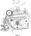
- Imaging system 20 includes an image forming device 22 and a computer 24.
- Image forming device 22 communicates with computer 24 via a communications link 26.
- communications link generally refers to any structure that facilitates electronic communication between multiple components and may operate using wired or wireless technology and may include communications over the Internet.
- image forming device 22 is a multifunction machine (sometimes referred to as an all-in-one (AIO) device) that includes a controller 28, a print engine 30, a laser scan unit (LSU) 31, an imaging unit 32, a toner cartridge 35, a user interface 36, a media feed system 38, a media input tray 39 and a scanner system 40.
- Image forming device 22 may communicate with computer 24 via a standard communication protocol, such as for example, universal serial bus (USB), Ethernet or IEEE 802.xx.
- Image forming device 22 may be, for example, an electrophotographic printer/copier including an integrated scanner system 40 or a standalone electrophotographic printer.
- Controller 28 includes a processor unit and associated memory 29 and may be formed as one or more Application Specific Integrated Circuits (ASICs).
- Memory 29 may be any volatile or non-volatile memory of combination thereof such as, for example, random access memory (RAM), read only memory (ROM), flash memory and/or non-volatile RAM (NVRAM).
- RAM random access memory
- ROM read only memory
- NVRAM non-volatile RAM
- memory 29 may be in the form of a separate electronic memory (e.g., RAM, ROM, and/or NVRAM), a hard drive, a CD or DVD drive, or any memory device convenient for use with controller 28.
- Controller 28 may be, for example, a combined printer and scanner controller.
- controller 28 communicates with print engine 30 via a communications link 50. Controller 28 communicates with imaging unit 32 and processing circuitry 44 thereon via a communications link 51. Controller 28 communicates with toner cartridge 35 and processing circuitry 45 therein via a communications link 52. Controller 28 communicates with media feed system 38 via a communications link 53. Controller 28 communicates with scanner system 40 via a communications link 54. User interface 36 is communicatively coupled to controller 28 via a communications link 55. Processing circuitry 44, 45 may provide authentication functions, safety and operational interlocks, operating parameters and usage information related to imaging unit 32 and toner cartridge 35, respectively. Controller 28 processes print and scan data and operates print engine 30 during printing and scanner system 40 during scanning.
- Computer 24, which is optional, may be, for example, a personal computer, including memory 60, such as RAM, ROM, and/or NVRAM, an input device 62, such as a keyboard and/or a mouse, and a display monitor 64.
- Computer 24 also includes a processor, input/output (I/O) interfaces, and may include at least one mass data storage device, such as a hard drive, a CD-ROM and/or a DVD unit (not shown).
- Computer 24 may also be a device capable of communicating with image forming device 22 other than a personal computer such as, for example, a tablet computer, a smartphone, or other electronic device.
- computer 24 includes in its memory a software program including program instructions that function as an imaging driver 66, e.g., printer/scanner driver software, for image forming device 22.
- Imaging driver 66 is in communication with controller 28 of image forming device 22 via communications link 26.
- Imaging driver 66 facilitates communication between image forming device 22 and computer 24.
- One aspect of imaging driver 66 may be, for example, to provide formatted print data to image forming device 22, and more particularly to print engine 30, to print an image.
- Another aspect of imaging driver 66 may be, for example, to facilitate collection of scanned data from scanner system 40.
- image forming device 22 it may be desirable to operate image forming device 22 in a standalone mode.
- image forming device 22 In the standalone mode, image forming device 22 is capable of functioning without computer 24. Accordingly, all or a portion of imaging driver 66, or a similar driver, may be located in controller 28 of image forming device 22 so as to accommodate printing and/or scanning functionality when operating in the standalone mode.
- Print engine 30 includes laser scan unit (LSU) 31, toner cartridge 35, imaging unit 32, and fuser 37, all mounted within image forming device 22.
- Imaging unit 32 is removably mounted in image forming device 22 and includes a developer unit 34 that houses a toner sump and a toner delivery system.
- the toner delivery system includes a toner adder roll that provides toner from the toner sump to a developer roll.
- a doctor blade provides a metered uniform layer of toner on the surface of the developer roll.
- Imaging unit 32 also includes a cleaner unit 33 that houses a photoconductive drum and a waste toner removal system.
- Toner cartridge 35 is also removably mounted in imaging unit 32 in a mating relationship with developer unit 34 of imaging unit 32.
- An exit port on toner cartridge 35 communicates with an entrance port on developer unit 34 allowing toner to be periodically transferred from toner cartridge 35 to resupply the toner sump in developer unit 34.
- laser scan unit 31 creates a latent image on the photoconductive drum in cleaner unit 33.
- Toner is transferred from the toner sump in developer unit 34 to the latent image on the photoconductive drum by the developer roll to create a toned image.
- the toned image is then transferred to a media sheet received in imaging unit 32 from media input tray 39 for printing.
- Toner remnants are removed from the photoconductive drum by the waste toner removal system.
- the toner image is bonded to the media sheet in fuser 37 and then sent to an output location or to one or more finishing options such as a duplexer, a stapler or a hole-punch.
- Imaging unit 200 includes a developer unit 202 and a cleaner unit 204 mounted on a common frame 206. As discussed above, imaging unit 200 and toner cartridge 100 are each removably installed in image forming device 22. Imaging unit 200 is first slidably inserted into image forming device 22. Toner cartridge 100 is then inserted into image forming device 22 and onto frame 206 in a mating relationship with developer unit 202 of imaging unit 200 as indicated by the arrow shown in Figure 2 . This arrangement allows toner cartridge 100 to be removed and reinserted easily when replacing an empty toner cartridge without having to remove imaging unit 200. Imaging unit 200 may also be readily removed as desired in order to maintain, repair or replace the components associated with developer unit 202, cleaning unit 204 or frame 206 or to clear a media jam.
- toner cartridge 100 includes a housing 102 having an enclosed reservoir 104 ( Figure 5 ) for holding a quantity of toner therein.
- Housing 102 may be viewed as having a top or lid 106 mounted on a base 108.
- Base 108 includes first and second side walls 110, 112 connected to adjoining front and rear walls 114, 116.
- top 106 is ultrasonically welded to base 108 thereby forming enclosed reservoir 104.
- First and second end caps 118, 120 are mounted to side walls 110, 112, respectively. First and second end caps 118, 120 may be snap fitted into place or attached by screws or other fasteners.
- a handle 122 may be provided on top 106 or base 108 of toner cartridge 100 to assist with insertion and removal of toner cartridge 100 from imaging unit 200 and image forming device 22.
- a fill port 124 is provided on side wall 112 that is used to fill toner cartridge 100 with toner. After filling, fill port 124 is closed by a plug 126 and/or cap 128.
- various drive gears are housed within a space formed between end cap 118 and side wall 110.
- a main interface gear 130 engages with a drive system in image forming device 22 that provides torque to main interface gear 130.
- a portion of main interface gear 130 is exposed between side wall 110 and end cap 118 on a front portion of toner cartridge 100 ( Figure 2 ).
- various linkages are housed within a space formed between end cap 120 and side wall 112.
- One or more paddles 134 are rotatably mounted within toner reservoir 104 with first and second ends of a drive shaft 136 of paddle(s) 134 extending through aligned openings in side walls 110, 112, respectively.
- the axis of drive shaft 136 is positioned below and spaced rearward from the axis of main interface gear 130.
- a drive gear 138 is provided on the first end of drive shaft 136 that engages with main interface gear 130 either directly or via one or more intermediate gears.
- Bushings may be provided on each end of drive shaft 136 where it passes through side walls 110, 112. Accordingly, side wall 110 may also be termed the "drive” or "driven” side of toner cartridge 100.
- an auger 140 having first and second ends 140a, 140b, and a spiral screw flight 140c is positioned in a channel 142 extending along the width of front wall 114 between side walls 110, 112.
- Channel 142 and the axis of auger 140 are positioned above the axis of drive shaft 136 but below the axis of main interface gear 130.
- Channel 142 and the axis of auger 140 are also spaced forward from the axes of drive shaft 136 and main interface gear 130.
- Channel 142 may be integrally molded as part of front wall 114 or formed as a separate component that is attached to front wall 114.
- Channel 142 is generally horizontal in orientation along with toner cartridge 100 when toner cartridge 100 is installed in image forming device 22.
- First end 140a of auger 140 extends through side wall 110 and a drive gear 144 is provided on first end 140a that engages with main interface gear 130 either directly or via one or more intermediate gears.
- Channel 142 includes an open portion 142a and an enclosed portion 142b. Open portion 142a is open to toner reservoir 104 and extends from side wall 110 toward second end 140b of auger 140. Enclosed portion 142b of channel 142 extends from side wall 112 and encloses a shutter assembly 150 ( Figure 7 ) and second end 140b of auger 140. As paddle(s) 134 rotate, they deliver toner from toner reservoir 104 into open portion 142a of channel 142.
- Auger 140 is rotated via drive gear 144 to deliver toner received in channel 142 to shutter assembly 150.
- Shutter assembly 150 regulates whether toner is permitted to exit toner cartridge 100 through an exit port 152 provided in front wall 114 and shown in Figure 7 .
- Exit port 152 is disposed at the bottom of channel 142 facing downward so that gravity will assist in exiting toner through exit port 152.
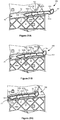
- Shutter assembly 150 is shown in more detail in Figures 8A, 8B, 9A and 9B .
- Shutter assembly 150 includes a shutter 154 that is rotatable between a closed position shown in Figures 8A and 9A and an open position shown in Figures 8B and 9B .
- Shutter 154 includes an open end 154a that receives second end 140b of auger 140 therein. As auger 140 rotates, it delivers toner from channel 142 to shutter 154.
- Shutter 154 includes a radial opening 154b that is connected to open end 154a by an internal channel in shutter 154. Radial opening 154b permits toner to exit toner cartridge 100 through exit port 152 as discussed in greater detail below.
- a retaining member 156 is mounted on side wall 112 of toner cartridge 100 ( Figure 7 ).
- retaining member 156 is a separate component attached to housing 102; however, retaining member 156 may also be integrally molded as part of housing 102.
- Retaining member 156 includes a bushing 158 that receives a closed end 154c of shutter 154. Closed end 154c of shutter 154 is connected to a lever 160 that opens and closes shutter 154.
- closed end 154c of shutter 154 includes a key 162 and lever 160 includes a corresponding keyway 164. Key 162 and keyway 164 couple shutter 154 to lever 160 such that the rotation of lever 160 opens and closes shutter 154.
- lever 160 includes a key and closed end 154c includes a corresponding keyway.
- lever 160 is connected to closed end 154c via a fastener 166 that passes through keyway 164 and a threaded hole 168 in closed end 154c; however, lever 160 and shutter 154 may be connected by any suitable means such as by being snap fit together.
- a post 170 is provided on the distal end of lever 160.
- shutter 154 When lever 160 is in a first position shown in Figures 8A and 9A , shutter 154 is in a closed position with radial opening 154b positioned against an internal surface of enclosed portion 142b of channel 142 in order to prevent toner from exiting toner cartridge 100.
- shutter 154 rotates to an open position where radial opening 154b is aligned with exit port 152 to permit toner to exit toner cartridge 100.
- toner may be delivered from reservoir 104 of toner cartridge 100 to imaging unit 200 by rotating paddle(s) 134 and auger 140 as desired.
- paddle(s) 134 rotate, they deliver toner from toner reservoir 104 into open portion 142a of channel 142.
- auger 140 As auger 140 rotates, it delivers toner received in channel 142 to shutter 154 through open end 154a. Toner passes through the internal channel in shutter 154 and out of radial opening 154b and exit port 152 into a corresponding entrance port 208 in developer unit 202 ( Figure 2 ).
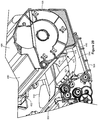
- FIG 10 shows a side view of cartridge 100 with end cap 120 removed to more clearly illustrate an example shutter lock mechanism 300 housed between side wall 112 and end cap 120.
- Shutter lock mechanism 300 includes a shutter linkage 310 that actuates lever 160 to open and close shutter 154 and an interlock 330 that prevents shutter 154 from opening unless toner cartridge 100 is installed within image forming device 22 and mated with imaging unit 200.
- shutter linkage 310 includes an outer linkage 312 and an inner linkage 314.
- Outer linkage 312 in one form, is forked having outer and inner side walls 320, 322, respectively, and includes an engagement surface 316, such as a button-like area, that is exposed through a rearward facing opening 175 in an exterior portion of housing 102 (see also Figures 2-4 ), such as a rear portion of end cap 120 next to lid 106 as shown.
- Inner linkage 314 is connected at one end to lever 160.
- inner linkage includes a channel 318 that receives post 170 extending from lever 160.
- inner linkage 314 and lever 160 may be connected by any suitable means such as, for example, by reversing the post/channel configuration such that inner linkage 314 includes a post and lever 160 includes a corresponding channel.
- Inner linkage 314 is pivotable about post 170 of lever 160.
- Outer linkage 312 and inner linkage 314 are elongated members that overlap with one another.
- inner linkage 314 is positioned in the fork between side walls 320, 322 of outer linkage 312; however, this configuration may be reversed as desired.
- Outer linkage 312 is biased by a suitable biasing member such as a spring (e.g., an extension spring) toward opening 175 where engagement surface 316 is exposed.
- a biasing member such as a spring (e.g., an extension spring) toward opening 175 where engagement surface 316 is exposed.
- inner linkage 314 is biased by a biasing member away from lever 160 so that shutter 154 is biased toward the closed position.
- interlock 330 is pivotally attached to side wall 112 at its axis of rotation 332.
- Interlock 330 includes a first leg 334 and a second leg 336 that each extend radially from axis 332.
- Second leg 336 includes a first portion 336a that extends radially from axis 332 and a second portion 336b that extends in a curved manner near the distal end of first portion 336a at an angle that is roughly perpendicular to first portion 336a.
- Second portion 336b of second leg 336 includes an engagement surface 340 that contacts an engagement feature, such as a fin 210 on frame 206 (or another engagement feature on imaging unit 200) to permit shutter 154 to open.
- first leg 334 includes a flexible member 342 at a distal end thereof.
- Flexible member 342 includes a curved engagement surface 344 ( Figure 11 ) on an outer surface thereof facing inner linkage 314.
- a bottom surface of inner linkage 314 (hidden behind the side wall of inner linkage 314) is supported by flexible member 342 on engagement surface 344.
- Interlock 330 is biased by one or more biasing members in the locked position shown in Figure 10 to prevent shutter 154 from opening prior to installation of toner cartridge 100 in image forming device 22 as discussed in greater detail below.
- toner cartridge 100 is inserted into image forming device 22, when an access door to image forming device 22 is closed, a plunger or other projection extending from an inner surface of the access door (or otherwise linked to the access door) presses engagement surface 316 overcoming the biasing force applied to outer linkage 312 and depressing both outer linkage 312 and inner linkage 314 causing lever 160 to rotate to open shutter 154 as shown in Figure 12 .
- engagement surface 316 is pressed, outer linkage 312 translates in the direction shown by the arrow in Figure 12 .
- Outer linkage 312 includes an elongated slot 346 that receives a corresponding post on end cap 120 or side wall 112. Slot 346 defines the path of movement of outer linkage 312.
- toner cartridge 100 When toner cartridge 100 is removed from image forming device 22, this sequence is reversed.
- outer linkage 312 and inner linkage 314 retract to their biased positions, closing shutter 154.
- fin 210 disengages from engagement surface 340 causing interlock 330 to rotate in a counter-clockwise direction (as viewed in Figures 10-12 ) to the locked position.
- interlock 330 rotates, inner linkage 314 lowers until top corner 328 is below the path of catch 326.
- shutter 154 This prevents shutter 154 from opening unless toner cartridge 100 is mated with imaging unit 200 in its final position in image forming device 22. As a result, shutter 154 will remain closed while toner cartridge 100 is removed from image forming device 22 even if engagement surface 316 is pressed.
- Shutter lock mechanism 300 prevents this from occurring. Shutter lock mechanism 300 also allows the user to close the access door to image forming device 22 without opening shutter 154 even if imaging unit 200 is not present. If outer linkage 312 was not free to pass inner linkage 314 when imaging unit 200 is not present, if a user tried to close the access door to image forming device 22, he or she would be unable to because interlock 330 would prevent outer linkage 312 and inner linkage 314 from moving.
- Lock mechanism 300 addresses this problem by permitting outer linkage 312 to travel past inner linkage 314 when interlock 330 is in the locked position. Lock mechanism 300 also reduces the likelihood that a user will accidentally release toner from toner cartridge 100 because it requires both engagement surface 316 and engagement surface 340 to be pressed in order to open shutter 154.
- toner cartridge 100 includes a rib or projection 176 projecting from front 114 of housing 102 spaced from exit port 152 near side wall 112.
- projection 176 is formed as part of retaining member 156.
- Projection 176 is positioned to actuate a shutter 209 ( Figure 16 ) that regulates whether toner is permitted to enter entrance port 208 on developer unit 202.
- shutter 209 Figure 16
- projection 176 contacts and opens shutter 209.
- projection 176 disengages from and closes shutter 209.
- projection 176 includes a forward projecting portion 177 that extends away from front wall 114 and a knob 178 that extends sideways from the front of forward projecting portion 177.
- toner cartridge 100 when toner cartridge 100 is installed in image forming device 22, its various interface features must align with corresponding interface features on imaging unit 200 and image forming device 22.
- toner cartridge 100 In its final position in image forming device 22, toner cartridge 100 is positioned above frame 206 of imaging unit 200 with exit port 152 ( Figure 3 ) aligned and mated with entrance port 208 on developer unit 202.
- exit port 152 and entrance port 208 In its final position, toner cartridge 100 does not apply a loading force on developer unit 202.
- Exit port 152 and entrance port 208 must be precisely aligned in order to prevent toner leakage between toner cartridge 100 and developer unit 202.
- main interface gear 130 must align and mate with a corresponding drive gear in image forming device 22 that provides torque to main interface gear 130.
- connector 145 includes a forward facing opening 145a for receiving the corresponding electrical contacts in image forming device 22.
- end cap 120 includes a tapered lead-in 145b that is aligned with opening 145a to guide the corresponding electrical contacts in image forming device 22 toward opening 145a as toner cartridge 100 is inserted.
- slot 174 must be positioned to receive fin 210 as toner cartridge 100 is inserted into image forming device 22 and opening 175 must be positioned to receive the projection from the access door to image forming device 22 in order to unlock interlock 330.
- the positions of these various interface points must be tightly controlled in order to ensure proper operation of toner cartridge 100.
- toner cartridge 100 must be properly positioned from front-to-rear (direction "x” in Figure 2 ), vertically (direction "y”) and side-to-side or axially (direction "z”).
- the angle of insertion of toner cartridge (“ ⁇ ") also referred to as yaw, must also be controlled to within an acceptable range in order to ensure proper positioning.
- toner cartridge 100 and imaging unit 200 include both coarse and fine axial positioning features.
- Toner cartridge 100 includes a pair of legs 146, 148 projecting downward from base 108. Legs 146, 148 are spaced along axial direction "z" from each other between end caps 118, 120. Legs 146, 148 extend along base 108 from a rear portion of toner cartridge toward front wall 114 parallel to direction of insertion "x.” A front portion of leg 148 includes slot 174 therein.
- Frame 206 of imaging unit 200 includes a pair of vertical walls 212, 214 that correspond with legs 146, 148.
- Each vertical wall 212, 214 includes a beveled front surface 212a, 214a that is outwardly angled with respect to the direction of insertion "x" and faces toner cartridge 100 as toner cartridge 100 advances toward imaging unit 200.
- Each vertical wall 212, 214 also includes an inner surface 212b, 214b that is substantially parallel to the direction of insertion "x" of toner cartridge 100. Inner surfaces 212b, 214b are spaced inward from front surfaces 212a, 214a, respectively, along direction "x" toward developer unit 202.
- front surfaces 212a, 214a guide toner cartridge 100 toward developer unit 202 and limit the travel of toner cartridge 100 in the axial direction "z.” If toner cartridge 100 is misaligned in the axial direction "z" during insertion, an outer surface 146a, 148a of one of its legs 146, 148 will contact the corresponding front surface 212a or 214a of vertical walls 212, 214. The angle of the front surface 212a or 214a will then urge toner cartridge 100 toward its proper axial alignment thereby providing coarse positional control as toner cartridge 100 advances toward developer unit 202.
- FIG. 17 illustrates a cross-sectional view of toner cartridge 100 and imaging unit 200 taken along line 17-17 in Figure 16 with toner cartridge 100 advanced closer to imaging unit 200.
- a vertical wall 216 is spaced inward from vertical wall 212 along axial direction "z" forming a slot 218 therebetween.
- slot 218 is formed between inner surface 212b of vertical wall 212 and an outer surface 216a of vertical wall 216.
- each end cap 118, 120 includes a wing guide 180, 190 (for end cap 120 and wing guide 190 see Figures 3 and 4 ).
- Each wing guide 180, 190 includes a generally elongated body 181, 191 that extends from a rear portion of its end cap 118, 120 toward a front portion thereof.
- Wing guides 180, 190 are substantially parallel to each other.
- wing guides 180, 190 each travel in a predetermined insertion path 70 defined by top and bottom guides 72, 74 running along an inner surface of image forming device 22.
- a top surface 182, 192 of each wing guide 180, 190 includes a substantially planar rear portion 182a, 192a that extends from a rear portion of its end cap 118, 120 toward a front portion thereof.
- Each top surface 182, 192 also includes a front portion 182b, 192b that is angled downward with respect to rear portion 182a, 192a, respectively.
- a stop 183, 193 extends vertically upward from each top surface 182, 192, respectively, that limits the forward travel of toner cartridge 100 as it is inserted into image forming device 22 as discussed in greater detail below.
- Each wing guide 180, 190 also includes a tapered nose 184, 194, respectively, forming a front tip thereof.
- a bottom surface 185, 195 of each respective wing guide 180, 190 includes three rounded projections 186a, 186b, 186c and 196a, 196b, 196c that define contact points with bottom guide 74 of image forming device 22.
- Wing guides 180, 190 are sometimes referred to as "dog bone” shaped because of the shape formed by bodies 181, 191 combined with rounded projections 186b, 186c and 196b, 196c.
- Top surface 182, 192 of each respective wing guide 180, 190 includes a pair of rounded projections 187a, 187b, 197a and 197b.
- Each end cap 118, 120 also includes an engagement surface 172, 173 projecting upwardly from a top portion of the respective end cap 118, 120.
- Each engagement surface 172, 173 includes an angled front surface 172a, 173a that faces imaging unit 200 during insertion and an angled rear surface 172b, 173b that faces away from imaging unit 200 during insertion.
- toner cartridge 100 As toner cartridge 100 is first inserted into image forming device 22, a roller 76 in image forming device 22 that is biased into the insertion path of toner cartridge 100 contacts front surfaces 172a, 173a of engagement surfaces 172, 173. The force applied to toner cartridge 100 by roller 76 controls the entry of toner cartridge 100 and prevents it from advancing into image forming device 22 too quickly. Further, as toner cartridge 100 is first inserted into image forming device 22, the downwardly angled front portions 182b, 192b and tapered nose 184, 194 of wing guides 180, 190 provide the user with a relatively broad range of permissible angles of insertion ⁇ (or yaw). As toner cartridge 100 advances, the insertion angle is limited by projections 187a, 187b, 197a, 197b on top surfaces 182, 192 and front projections 186a, 196a on bottom surfaces 185, 195 as shown.
- roller 76 passes over an apex 172c, 173c of each engagement surface 172, 173 until it contacts rear surfaces 172b, 173b.
- the force applied by roller 76 to rear surfaces 172b, 173b of toner cartridge 100 urges toner cartridge 100 to its final position in image forming device 22.
- toner cartridge 100 advances, stops 183, 193 contact top guide 72 in image forming device 22 to prevent toner cartridge 100 from advancing further thereby controlling the front-to-rear horizontal positioning of toner cartridge 100 along direction "x."
- the vertical position of toner cartridge 100 along direction "y" is controlled by the contact between rounded projections 186b, 186c, 196b, 196c and bottom guides 74 in image forming device 22.
- three of the four rounded projections 186b, 186c, 196b, 196c form datum points that define a plane that determines the vertical position of toner cartridge 100.
- rounded projections 186b, 186c and 196b are the same while the radius of rounded projection 196c is slightly smaller.
- rounded projections 186b, 186c and 196b control the vertical position of toner cartridge 100.
- toner cartridge 100 permits proper alignment between the various interface features of toner cartridge 100 and the corresponding interface features on imaging unit 200 and image forming device 22.
- exit port 152 of toner cartridge 100 is aligned and mated with entrance port 208 on developer unit 202.
- Main interface gear 130 is aligned and mated with a corresponding drive gear 78 in image forming device 22.
- Electrical contacts for the processing circuitry in connector 145 are aligned and mated with corresponding electrical contacts on a connector 80 in image forming device 22.
- the positional control features of toner cartridge 100 ensure that these interface points are tightly controlled in order to ensure proper operation of toner cartridge 100.
- the force applied by roller 76 on rear surfaces 172b, 173b of engagement surfaces 172, 173 holds toner cartridge 100 in position and prevents it from separating from entrance port 208, drive gear 78 or electrical contacts 80.
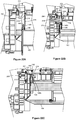
- Figures 20A-C , 21A-C and 22A-C are sequential views illustrating the insertion of toner cartridge 100 into image forming device 22.
- Figures 20A-C and 21A-C show the positions of wing guides 180, 190, respectively, relative to insertion path 70 as toner cartridge 100 is inserted into image forming device 22.
- Figures 22A-C show cross-sectional views of leg 146 of toner cartridge 100 taken along line 22-22 in Figure 2 .
- Figures 20A , 21A and 22A show a first sequence view as toner cartridge 100 is initially inserted into image forming device 22.
- Figures 20A and 21A show wing guides 180, 190, respectively, entering their respective insertion paths 70.
- Figure 22A shows a front portion 180 of leg 146 entering slot 218 in frame 206.
- front portion 146b of leg 146 tapers in width forming a tab or nose 146c at a front tip thereof.
- the width of nose 146c is between about 5 mm and about 9 mm.
- Slot 218 includes a corresponding tapered lead-in 220 to receive and guide front portion 146b of leg 146 into slot 218.
- Slot 218 also includes an inner slot portion 222 sized to tightly receive nose 146c.
- Figures 20B , 21B and 22B show a second sequence view as toner cartridge 100 is advanced further into image forming device 22.
- Figures 20B and 21B show wing guides 180, 190, respectively, advanced further along their respective insertion paths 70.
- Figure 22B shows front portion 146b of leg 146 advanced further in slot 218.
- Figures 20C , 21C and 22C show a final sequence view with toner cartridge 100 fully inserted into image forming device 22 and mated with developer unit 202.
- Figures 20C and 21C show stops 183, 193 engaged with a corresponding lip or rounded stop 82 in image forming device 22. Stops 82 control the position of toner cartridge 100 in the direction of insertion and ensure that toner cartridge 100 is not over-inserted into image forming device 22.
- Figures 20C and 21C also show rounded projections 186b, 186c and 196b, positioned on bottom guide 74 and rounded projections 186a, 196a and 196c spaced from bottom guide 74.
- rounded projections 186b, 186c and 196b define a plane that controls the vertical position of toner cartridge 100.
- Figure 22C shows nose 146c tightly positioned in inner slot portion 222 to control the axial position of toner cartridge 100.
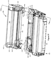
- Imaging unit 500 includes a developer unit 502 and a cleaner unit 504 mounted on a common frame 506.
- Developer unit 502 includes an entrance port 508 for receiving toner from toner cartridge 400.
- Frame 506 includes a projection 510 for actuating a shutter that regulates the flow of toner out of toner cartridge 400 similar to fin 210 discussed above.
- imaging unit 500 and toner cartridge 400 are each removably installed in image forming device 22. In its final position, toner cartridge 400 is in a mating relationship with developer unit 502 of imaging unit 500.
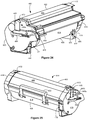
- Toner cartridge 400 includes a housing 402 having a top or lid 406 mounted on a base 408.
- Housing 402 includes an enclosed reservoir therein for holding toner as discussed above.
- the internal components of the reservoir of toner cartridge 400 e.g., the paddles, drive shaft, channel, and auger
- Base 408 includes first and second side walls connected to adjoining front and rear walls 414, 416.
- First and second end caps 418, 420 are mounted to the side walls (hidden by end caps 418, 420), respectively.
- a handle 422 may be provided on top 406 or base 408 of toner cartridge 400 as desired.
- a main interface gear 430 is exposed on front wall 414 between end cap 418 and its respective side wall.
- Main interface gear 430 engages with a drive system in image forming device 22 that provides torque to main interface gear 430.
- Various additional drive gears are housed within a space formed between end cap 418 and side wall 410 as discussed above with respect to toner cartridge 100.
- various linkages are housed within a space formed between end cap 420 and side wall 412.
- An exit port 452 is disposed on front wall 414 in a downward facing orientation so that gravity will assist in exiting toner through exit port 452.
- Shutter assembly 150 discussed above may be used to regulate whether toner is permitted to exit toner cartridge 400 through exit port 452.
- Toner cartridge 400 also includes a connector 445 positioned on end cap 420 having electrical contacts for the processing circuitry of toner cartridge 400.
- Connector 445 includes a forward facing opening 445a for receiving the corresponding electrical contacts in image forming device 22.
- end cap 420 includes a tapered lead-in 445b that is aligned with opening 445a to guide the corresponding electrical contacts in image forming device 22 toward opening 445a as toner cartridge 400 is inserted.
- toner cartridge 400 includes a rib or projection 476 projecting from front 414 of housing 402 near side wall 412 for actuating a shutter 509 ( Figure 27 ) that regulates whether toner is permitted to enter entrance port 508 on developer unit 502 as discussed above.
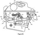
- toner cartridge 400 may include a shutter lock mechanism 600 according to another example embodiment.
- End cap 420 is removed in Figure 26 to more clearly illustrate shutter lock mechanism 600.
- Shutter lock mechanism 600 includes a shutter linkage 610 that actuates a lever 460 to open and close the shutter as discussed above and an interlock 630 that prevents the shutter from opening unless toner cartridge 400 is installed within image forming device 22 and mated with imaging unit 500.
- shutter linkage 610 includes an outer linkage 612 and an inner linkage 614.
- Outer linkage 612 in one form, is forked having an outer side wall 620 and an inner side wall (hidden behind outer side wall 620).
- Outer linkage 612 includes an engagement surface 616, such as a button-like area, that is exposed through a rearward facing opening 475 to an exterior portion of housing 402, such as a rear portion of end cap 420 next to base 408 as shown (see also Figure 25 ).
- Inner linkage 614 is connected at one end to lever 460.
- inner linkage includes a channel 618 that receives a post 470 extending from lever 460; however, as discussed above, this connection may be established by any suitable means.
- Outer linkage 612 and inner linkage 614 are elongated members that overlap with one another.
- inner linkage 614 is positioned in the fork between outer side wall 620 and the inner side wall of outer linkage 612; however, this configuration may be reversed as desired.
- Outer linkage 612 is biased by a suitable biasing member toward opening 475 where engagement surface 616 is exposed.
- inner linkage 614 is biased by a biasing member away from lever 460 so that the shutter is biased toward the closed position.
- an inner surface of outer linkage 612 includes a catch that engages a portion of inner linkage 614 when interlock 630 is unlocked but clears inner linkage 614 when interlock 630 is locked.
- interlock 630 is pivotally attached to side wall 412 at its axis of rotation 632.
- Interlock 630 extends along side wall 412 from its attachment point 632 toward front wall 414.
- Interlock 630 includes a curved or ramped engagement surface 634 that contacts an engagement feature, such as projection 510, on imaging unit 500 to permit the shutter to open.
- Interlock 630 also includes an upward extending post 636 that raises inner linkage 614 when interlock 630 is unlocked as discussed below.
- Interlock 630 is biased by one or more biasing members in the locked position shown in Figure 26 to prevent the shutter from opening prior to installation of toner cartridge 400 in image forming device 22.
- an engagement feature on imaging unit 500 such as projection 510, contacts engagement surface 634 of interlock 630.
- the force from the engagement feature on interlock 630 overcomes the biasing force applied to interlock 630 and causes it to rotate in a counter-clockwise direction (as viewed in Figure 26 ) to the unlocked position.
- the counter-clockwise rotation of interlock 630 causes post 636 to contact a bottom portion 624 of inner linkage 614 and raise inner linkage 614 into the path of the catch on outer linkage 612 as discussed above.
- a slot such as forward facing slot 474 shown in Figure 24 , may be provided in base 408 and/or end cap 420 of toner cartridge 400 to receive the engagement feature 510.
- a plunger or other projection extending from an inner surface of the access door (or otherwise linked to the access door) presses engagement surface 616 overcoming the biasing force applied to outer linkage 612 and depressing both outer linkage 612 and inner linkage 614 causing lever 460 to rotate to open the shutter.
- toner cartridge 400 When toner cartridge 400 is removed from image forming device 22, this sequence is reversed.
- outer linkage 612 and inner linkage 614 retract to their biased positions, closing the shutter.
- engagement feature 510 disengages from engagement surface 634 causing interlock 630 to rotate in a clockwise direction (as viewed in Figure 26 ).
- interlock 630 rotates, inner linkage 614 lowers until it clears the path of the catch on outer linkage 612.
- the shutter will remain closed while toner cartridge 400 is removed from image forming device 22 even if engagement surface 616 is pressed.
- a locking mechanism such as locking mechanisms 300 and 600, having a shutter linkage and an interlock may be employed to ensure that a shutter, such as shutter 154, remains closed unless the toner cartridge is installed in the image forming device and mated with its corresponding imaging unit.
- an outer linkage that is capable of sliding past an inner linkage when the interlock is locked allows the user to close the access door to the image forming device when the imaging unit is not present without opening the shutter or damaging the image forming device or the toner cartridge.
- the user is also able to press the engagement surface of the shutter linkage, such as engagement surface 316 or 616, without opening the shutter.
- toner cartridge 400 and imaging unit 500 include both coarse and fine axial positioning features.
- the coarse axial positioning features are similar to those discussed above with respect to toner cartridge 100 and imaging unit 200.
- Toner cartridge 400 includes a pair of legs 446, 448 extending downward from base 408.
- Frame 506 of imaging unit 500 includes a pair of vertical walls 512, 514 that form a guide 516 therebetween that receives leg 446 and a pair of vertical walls 518, 520 that form a guide 522 therebetween that receives leg 448 as toner cartridge 400 is inserted into image forming device 22.
- Each vertical wall 512, 514, 518, 520 includes a beveled front surface 512a, 514a, 518a, 520a that is outwardly angled with respect to the direction of insertion and faces toner cartridge 400 as toner cartridge 400 advances toward imaging unit 500. Front surfaces 512a, 514a, 518a, 520a guide toner cartridge 400 toward developer unit 502 as toner cartridge 400 is inserted into image forming device 22. Each vertical wall 512, 514, 518, 520 also includes an inner surface 512b, 514b, 518b, 520b that is substantially parallel to the direction of insertion of toner cartridge 400.
- Inner surfaces 512b, 514b, 518b, 520b restrain outer surfaces 446a, 448a of legs 446, 448 limiting the travel of toner cartridge 400 in the axial direction.
- the distance between outer surface 446a of leg 446 and outer surface 448a of leg 448 is between about 255 mm and about 258 mm.
- Figure 28 illustrates a cross-sectional view of toner cartridge 400 and imaging unit 500 taken along line 28-28 in Figure 27 .
- a post 524 is spaced axially inward from guide 516 and extends upward from frame 506 of imaging unit 500.
- Toner cartridge 400 includes a slot 477 formed between a pair of substantially parallel walls 478, 479 that extend forward and downward from base 408. Slot 477 is spaced axially inward from leg 446. In the example embodiment illustrated in Figure 28 , the width of slot 477 is between about 6.3 mm and about 8.3 mm.
- post 524 on imaging unit 500 is tightly received in slot 477 on toner cartridge 400 permitting slot 477 to precisely maintain the axial position of toner cartridge 400.
- post 524 and/or slot 477 may include a tapered lead-in section to facilitate engagement between the two.
- each end cap 418, 420 includes a wing guide 480, 490.
- Each wing guide 480, 490 includes the "dog bone” structure described above with respect to wing guides 180, 190 of toner cartridge 100.
- wing guides 480, 490 control the front-to-rear horizontal positioning and vertical positioning of toner cartridge 400.
- Each end cap 418, 420 also includes an engagement surface 472, 473 projecting upwardly from a top portion of the respective end cap 418, 420.
- each engagement surface 472, 473 includes an angled front surface 472a, 473a that faces imaging unit 500 during insertion and an angled rear surface 472b, 473b that faces away from imaging unit 500 during insertion.
- rear surfaces 472b, 473b of engagement surfaces 472, 473 receive a hold-down force from a component in image forming device 22 to ensure that exit port 452, main interface gear 430, the electrical contacts in connector 445 and the engagement surfaces for shutter lock mechanism 600 maintain their engagement with imaging unit 500 or image forming device 22.
Landscapes
- Physics & Mathematics (AREA)
- General Physics & Mathematics (AREA)
- Engineering & Computer Science (AREA)
- Computer Vision & Pattern Recognition (AREA)
- Dry Development In Electrophotography (AREA)
- Electrophotography Configuration And Component (AREA)
- Ink Jet (AREA)
Priority Applications (4)
| Application Number | Priority Date | Filing Date | Title |
|---|---|---|---|
| EP18152015.6A EP3346340B1 (en) | 2011-12-30 | 2012-11-15 | Toner cartridge for use in an image forming device |
| DK18151992.7T DK3330804T3 (da) | 2011-12-30 | 2012-11-15 | Tonerpatron til anvendelse i en billeddannelsesindretning |
| EP18151992.7A EP3330804B1 (en) | 2011-12-30 | 2012-11-15 | Toner cartridge for use in an image forming device |
| PL18151992T PL3330804T3 (pl) | 2011-12-30 | 2012-11-15 | Kaseta tonerowa do użytkowania w urządzeniu tworzącym obrazy |
Applications Claiming Priority (2)
| Application Number | Priority Date | Filing Date | Title |
|---|---|---|---|
| US13/340,935 US8867966B2 (en) | 2011-12-30 | 2011-12-30 | Toner cartridge for use in an image forming device |
| PCT/US2012/065149 WO2013101350A2 (en) | 2011-12-30 | 2012-11-15 | Toner cartridge for use in an image forming device |
Related Child Applications (4)
| Application Number | Title | Priority Date | Filing Date |
|---|---|---|---|
| EP18152015.6A Division-Into EP3346340B1 (en) | 2011-12-30 | 2012-11-15 | Toner cartridge for use in an image forming device |
| EP18152015.6A Division EP3346340B1 (en) | 2011-12-30 | 2012-11-15 | Toner cartridge for use in an image forming device |
| EP18151992.7A Division-Into EP3330804B1 (en) | 2011-12-30 | 2012-11-15 | Toner cartridge for use in an image forming device |
| EP18151992.7A Division EP3330804B1 (en) | 2011-12-30 | 2012-11-15 | Toner cartridge for use in an image forming device |
Publications (3)
| Publication Number | Publication Date |
|---|---|
| EP2798411A2 EP2798411A2 (en) | 2014-11-05 |
| EP2798411A4 EP2798411A4 (en) | 2016-01-13 |
| EP2798411B1 true EP2798411B1 (en) | 2018-04-18 |
Family
ID=48694904
Family Applications (3)
| Application Number | Title | Priority Date | Filing Date |
|---|---|---|---|
| EP12863609.9A Active EP2798411B1 (en) | 2011-12-30 | 2012-11-15 | Toner cartridge for use in an image forming device |
| EP18151992.7A Active EP3330804B1 (en) | 2011-12-30 | 2012-11-15 | Toner cartridge for use in an image forming device |
| EP18152015.6A Active EP3346340B1 (en) | 2011-12-30 | 2012-11-15 | Toner cartridge for use in an image forming device |
Family Applications After (2)
| Application Number | Title | Priority Date | Filing Date |
|---|---|---|---|
| EP18151992.7A Active EP3330804B1 (en) | 2011-12-30 | 2012-11-15 | Toner cartridge for use in an image forming device |
| EP18152015.6A Active EP3346340B1 (en) | 2011-12-30 | 2012-11-15 | Toner cartridge for use in an image forming device |
Country Status (22)
| Country | Link |
|---|---|
| US (7) | US8867966B2 (ko) |
| EP (3) | EP2798411B1 (ko) |
| KR (1) | KR101554462B1 (ko) |
| CN (2) | CN104380212B (ko) |
| AR (1) | AR089370A1 (ko) |
| AU (1) | AU2012363069B2 (ko) |
| BR (1) | BR112014012764B8 (ko) |
| CA (2) | CA2910823C (ko) |
| CL (1) | CL2014001369A1 (ko) |
| CO (1) | CO7030943A2 (ko) |
| DK (1) | DK3330804T3 (ko) |
| ES (2) | ES2673491T3 (ko) |
| HK (3) | HK1204096A1 (ko) |
| IL (1) | IL232579A0 (ko) |
| IN (1) | IN2014DN05922A (ko) |
| MX (1) | MX337200B (ko) |
| PL (1) | PL3330804T3 (ko) |
| RU (1) | RU2589769C2 (ko) |
| SG (1) | SG11201402377PA (ko) |
| TW (1) | TWI515121B (ko) |
| WO (1) | WO2013101350A2 (ko) |
| ZA (1) | ZA201403289B (ko) |
Families Citing this family (59)
| Publication number | Priority date | Publication date | Assignee | Title |
|---|---|---|---|---|
| US8867968B2 (en) | 2011-12-30 | 2014-10-21 | Lexmark International, Inc. | Movable toner port cover member for a replaceable unit of an imaging device |
| US8682213B2 (en) * | 2011-12-30 | 2014-03-25 | Lexmark International, Inc. | Toner cartridge having a shutter lock mechanism |
| US8649710B2 (en) | 2011-12-30 | 2014-02-11 | Lexmark International, Inc. | Toner cartridge having a pivoting exit port cover |
| US8948650B2 (en) * | 2011-12-30 | 2015-02-03 | Lexmark International, Inc. | Toner cartridge having a shutter lock mechanism |
| US8879953B2 (en) | 2012-06-25 | 2014-11-04 | Lexmark International, Inc. | Retainer assembly having positioning features for processing circuitry used within an image forming device supply item |
| US8938179B2 (en) * | 2012-06-25 | 2015-01-20 | Lexmark International, Inc. | Toner cartridge for an image forming device having a retainer assembly having positioning features for processing circuitry |
| US9063460B2 (en) | 2012-09-14 | 2015-06-23 | Lexmark International, Inc. | Volumetric toner cartridge having driven toner platform |
| US8918032B2 (en) * | 2012-09-14 | 2014-12-23 | Lexmark International, Inc. | Volumetric toner cartridge having toner agitators |
| US8923734B2 (en) | 2012-09-14 | 2014-12-30 | Lexmark International, Inc. | Volumetric toner cartridge having removable exit paddle |
| US9152083B2 (en) | 2013-10-09 | 2015-10-06 | Lexmark International, Inc. | Carriage assembly for toner cartridge loading and latching |
| US9280087B2 (en) | 2013-11-20 | 2016-03-08 | Lexmark International, Inc. | Electrophotographic image forming device latching system for retaining a replaceable unit |
| US9261851B2 (en) | 2013-11-20 | 2016-02-16 | Lexmark International, Inc. | Positional control features of a replaceable unit for an electrophotographic image forming device |
| US8761639B1 (en) * | 2013-11-20 | 2014-06-24 | Lexmark International, Inc. | Replaceable unit for an electrophotographic image forming device having a latching mechanism |
| CN112650038B (zh) | 2014-08-01 | 2024-05-10 | 佳能株式会社 | 调色剂盒、调色剂供给机构和闸板 |
| US9285758B1 (en) | 2014-12-19 | 2016-03-15 | Lexmark International, Inc. | Positional control features between replaceable units of an electrophotographic image forming device |
| US9291992B1 (en) | 2014-12-19 | 2016-03-22 | Lexmark International, Inc. | Positional control features for an imaging unit in an electrophotographic image forming device |
| US9317004B1 (en) | 2015-04-10 | 2016-04-19 | Lexmark International, Inc. | Handle and positioning stop assembly for a replaceable unit of an electrophotographic image forming device |
| WO2016208282A1 (ja) * | 2015-06-25 | 2016-12-29 | 京セラドキュメントソリューションズ株式会社 | トナー容器を装着可能な画像形成装置 |
| US9477178B1 (en) * | 2015-08-13 | 2016-10-25 | Lexmark International, Inc. | System for determining the open or closed state of a toner cartridge shutter |
| US9360797B1 (en) * | 2015-08-13 | 2016-06-07 | Lexmark International, Inc. | Toner cartridge having a movable projection for providing installation feedback to an image forming device |
| US9360834B1 (en) * | 2015-09-15 | 2016-06-07 | Lexmark International, Inc. | Replaceable unit for an electrophotographic image forming device having positioning features for electrical contacts |
| US9551974B1 (en) | 2015-09-15 | 2017-01-24 | Lexmark International, Inc. | Positioning features for electrical connectors of replaceable units of an image forming device |
| US9563169B1 (en) * | 2015-12-14 | 2017-02-07 | Lexmark International, Inc. | Replaceable unit for an electrophotographic image forming device having a retractable electrical connector |
| US9910403B2 (en) | 2016-01-18 | 2018-03-06 | Lexmark International, Inc. | Positioning features for electrical contacts of a replaceable unit of an electrophotographic image forming device |
| CN114153130A (zh) | 2016-09-30 | 2022-03-08 | 佳能株式会社 | 调色剂盒和调色剂供应机构 |
| US10139776B1 (en) | 2017-05-11 | 2018-11-27 | Lexmark International, Inc. | Electrical connector assembly for use in an image forming device |
| US9989917B1 (en) * | 2017-05-17 | 2018-06-05 | Lexmark International, Inc. | Toner cartridge with positional control features |
| USD841730S1 (en) * | 2017-06-30 | 2019-02-26 | Lexmark International, Inc. | Toner cartridge |
| USD854078S1 (en) * | 2017-06-30 | 2019-07-16 | Lexmark International, Inc. | Toner cartridge |
| US10310410B2 (en) * | 2017-07-21 | 2019-06-04 | Canon Kabushiki Kaisha | Development cartridge, process cartridge, and image forming apparatus |
| US10185247B1 (en) | 2017-10-23 | 2019-01-22 | Lexmark International, Inc. | Toner cartridge having a media feed roll assembly |
| US10444661B2 (en) | 2017-10-23 | 2019-10-15 | Lexmark International, Inc. | Toner cartridge having a biasing assembly for biasing a media feed roll in an electrophotographic image forming device |
| US10474061B2 (en) | 2018-02-23 | 2019-11-12 | Lexmark International, Inc. | Reduced capacity toner cartridge for an electrophotographic image forming device having an isolated toner volume surrounding an auger of the toner cartridge |
| US11454921B2 (en) | 2018-08-30 | 2022-09-27 | Hewlett-Packard Development Company, L.P. | Contacts for a print particle input recess |
| ES2959315T3 (es) | 2018-08-30 | 2024-02-23 | Hewlett Packard Development Co | Conjunto de salida de partículas de impresión |
| KR102390147B1 (ko) | 2018-08-30 | 2022-04-25 | 휴렛-팩커드 디벨롭먼트 컴퍼니, 엘.피. | 현상 카트리지와 본체 간의 인터페이스를 통해 본체에 연결되는 토너 리필 카트리지 |
| US10527969B1 (en) | 2018-10-11 | 2020-01-07 | Lexmark International, Inc. | Drive actuation of a toner agitator assembly and an encoded member of a toner container in an electrophotographic image forming device |
| US11022909B2 (en) | 2018-10-11 | 2021-06-01 | Lexmark International, Inc. | Toner container having an encoded member and an alignment guide for locating a sensor relative to the encoded member |
| US11022910B2 (en) | 2018-10-11 | 2021-06-01 | Lexmark International, Inc. | Sensor positioning by a replaceable unit of an image forming device |
| US10527967B1 (en) * | 2018-10-11 | 2020-01-07 | Lexmark International, Inc. | Toner container having a common input gear for a toner agitator assembly and an encoded member |
| US10725422B2 (en) * | 2018-10-25 | 2020-07-28 | Lexmark International, Inc. | Toner cartridge electrical contacts |
| US10782643B2 (en) * | 2018-11-05 | 2020-09-22 | Lexmark International, Inc. | Toner cartridge having positioning features |
| US10656592B1 (en) | 2019-01-09 | 2020-05-19 | Lexmark International, Inc. | Toner cartridge having positioning features |
| US10474093B1 (en) | 2019-02-05 | 2019-11-12 | Lexmark International, Inc. | Toner cartridge having a positioning boss |
| EP3942370B1 (en) * | 2019-03-22 | 2024-04-24 | Lexmark International, Inc. | Toner container having an encoded member and an alignment guide for locating a sensor relative to the encoded member |
| US10761476B1 (en) | 2019-04-12 | 2020-09-01 | Lexmark International, Inc. | Replaceable unit for an electrophotographic image forming device having a movable electrical connector |
| US10649389B1 (en) | 2019-04-12 | 2020-05-12 | Lexmark International, Inc. | Electrical connectors of a replaceable unit of an electrophotographic image forming device |
| US10698363B1 (en) | 2019-04-12 | 2020-06-30 | Lexmark International, Inc. | Electrical connection for an imaging unit of an electrophotographic image forming device |
| US10649399B1 (en) | 2019-04-12 | 2020-05-12 | Lexmark Internatioanl, Inc. | Replaceable unit for an electrophotographic image forming device having a magnetic sensor |
| JP7371347B2 (ja) * | 2019-05-15 | 2023-10-31 | 京セラドキュメントソリューションズ株式会社 | 画像形成装置 |
| US10809661B1 (en) | 2019-06-03 | 2020-10-20 | Lexmark International, Inc. | Toner cartridge having positioning features including guides extending outward from sides of the toner cartridge and an engagement member on a rear of the toner cartridge |
| US10725424B1 (en) | 2019-06-03 | 2020-07-28 | Lexmark International, Inc. | Imaging unit assembly for an electrophotographic image forming device |
| CN110221529A (zh) * | 2019-06-10 | 2019-09-10 | 江西凯利德科技有限公司 | 一种显影剂补充盒及显影剂补充方法 |
| JP7305105B2 (ja) * | 2019-07-16 | 2023-07-10 | 株式会社リコー | 現像剤補給装置、及び、画像形成装置 |
| EP3997523A4 (en) | 2019-10-08 | 2023-04-26 | Hewlett-Packard Development Company, L.P. | FLUID CHANNEL DEVELOPMENT UNIT GASKETS |
| USD952030S1 (en) * | 2019-10-23 | 2022-05-17 | Lexmark International, Inc. | Toner cartridge |
| US11347180B2 (en) | 2019-12-27 | 2022-05-31 | Lexmark International, Inc. | Shipping or storage separator for replaceable units of an electrophotographic image forming device |
| US11137699B1 (en) | 2020-06-01 | 2021-10-05 | Lexmark International, Inc. | Toner container having a reduced auger flight to accommodate bi-directional rotation of the auger |
| KR20230024746A (ko) * | 2021-08-12 | 2023-02-21 | 휴렛-팩커드 디벨롭먼트 컴퍼니, 엘.피. | 하나의 구동 모터로 토너 운반 부재와 토너 리필 카트리지를 구동하는 구조 |
Family Cites Families (145)
| Publication number | Priority date | Publication date | Assignee | Title |
|---|---|---|---|---|
| US4839691A (en) | 1986-03-31 | 1989-06-13 | Kabushiki Kaisha Toshiba | Image forming apparatus |
| DE3716152A1 (de) | 1987-05-14 | 1988-11-24 | Standard Elektrik Lorenz Ag | An einer montageplatte schwimmend befestigte steckkupplung |
| EP0331324B1 (en) * | 1988-03-02 | 1993-09-08 | Canon Kabushiki Kaisha | Image forming apparatus usable with process cartridge detachably mountable thereto |
| JPH0833704B2 (ja) | 1988-03-18 | 1996-03-29 | キヤノン株式会社 | プロセスカートリッジ及び画像形成装置 |
| US4891017A (en) | 1988-04-26 | 1990-01-02 | Amp Incorporated | Socket connector with pin aligning housing |
| JPH03134674A (ja) | 1989-10-20 | 1991-06-07 | Canon Inc | プロセスカートリッジ |
| JPH066377Y2 (ja) | 1989-10-25 | 1994-02-16 | ブラザー工業株式会社 | 感光体カートリッジ |
| US5002497A (en) | 1990-01-26 | 1991-03-26 | Molex Incorporated | Floatable panel mountable electrical connector assembly |
| JPH0470779A (ja) | 1990-07-11 | 1992-03-05 | Ricoh Co Ltd | トナー補給装置 |
| DE69210534T2 (de) | 1991-04-10 | 1996-10-02 | Canon Kk | Prozesskartusche und verfahren zur montage der prozesskartusche |
| JP2774731B2 (ja) | 1991-04-19 | 1998-07-09 | シャープ株式会社 | 画像形成装置のプロセスキット |
| JP2568142B2 (ja) | 1991-12-30 | 1996-12-25 | モレックス インコーポレーテッド | フローティング構造の電気コネクタ及びその製法 |
| NL9200884A (nl) | 1992-05-20 | 1993-12-16 | Framatome Connectors Belgium | Connectorsamenstel. |
| JP3044997B2 (ja) | 1994-02-16 | 2000-05-22 | ブラザー工業株式会社 | 画像形成装置における現像装置 |
| US5490802A (en) | 1994-02-24 | 1996-02-13 | United Technologies Automotive, Inc. | Secondary terminal lock plug through stuffer |
| US5614996A (en) | 1994-03-03 | 1997-03-25 | Kyocera Corporation | Toner storage unit, residual toner collect unit, toner container with these units and image forming apparatus with such toner container |
| US5686985A (en) | 1994-08-31 | 1997-11-11 | Kyocera Corporation | Toner container and developing device with the same toner container assembled therein |
| US5605150A (en) | 1994-11-04 | 1997-02-25 | Physio-Control Corporation | Electrical interface for a portable electronic physiological instrument having separable components |
| JP2994974B2 (ja) | 1994-11-30 | 1999-12-27 | シャープ株式会社 | 現像装置 |
| KR0129183Y1 (ko) | 1995-03-09 | 1999-03-20 | 김광호 | 화상형성 장치의 토너 누출 방지 장치 |
| JP3466769B2 (ja) | 1995-04-17 | 2003-11-17 | キヤノン株式会社 | 画像形成装置、プロセスカートリッジ及び現像装置 |
| US6070029A (en) | 1995-07-31 | 2000-05-30 | Canon Kabushiki Kaisha | Coupling member, process cartridge, electrophotographic image forming apparatus and assembling method |
| JP3471992B2 (ja) * | 1995-10-26 | 2003-12-02 | キヤノン株式会社 | トナー補給容器及び画像形成装置 |
| JPH09213407A (ja) | 1996-01-31 | 1997-08-15 | Canon Inc | コネクタ及びユニット及びプロセスカートリッジ及び電子写真画像形成装置 |
| US5746617A (en) | 1996-07-03 | 1998-05-05 | Quality Microwave Interconnects, Inc. | Self aligning coaxial connector assembly |
| JP3363751B2 (ja) | 1996-08-29 | 2003-01-08 | キヤノン株式会社 | プロセスカートリッジ及び電子写真画像形成装置 |
| US5768661A (en) * | 1996-12-20 | 1998-06-16 | Lexmark International, Inc. | Toner cartridge with external planar installation guides |
| US5875378A (en) * | 1996-12-20 | 1999-02-23 | Lexmark International, Inc. | Toner cartridge with hopper exit agitator |
| US5758233A (en) | 1996-12-20 | 1998-05-26 | Lexmark International, Inc. | Toner cartridge with locating on photoconductor shaft |
| US6168262B1 (en) | 1997-01-30 | 2001-01-02 | Hewlett-Packard Company | Electrical interconnect for replaceable ink containers |
| JPH10312870A (ja) | 1997-05-12 | 1998-11-24 | Canon Inc | コネクタ及びユニット及びプロセスカートリッジ及び画像形成装置 |
| JP3408153B2 (ja) | 1997-06-19 | 2003-05-19 | キヤノン株式会社 | トナー補給容器及び電子写真画像形成装置 |
| JP3368205B2 (ja) | 1997-06-19 | 2003-01-20 | キヤノン株式会社 | トナー補給容器及び電子写真画像形成装置 |
| US6968139B2 (en) | 1997-06-19 | 2005-11-22 | Canon Kabushiki Kaisha | Toner supply container and electrophotographic image forming apparatus |
| JP3697065B2 (ja) | 1997-06-19 | 2005-09-21 | キヤノン株式会社 | トナー補給容器、及び、電子写真画像形成装置 |
| JPH11153904A (ja) | 1997-09-17 | 1999-06-08 | Mitsubishi Electric Corp | トナーカートリッジ |
| JPH11242371A (ja) | 1997-10-31 | 1999-09-07 | Canon Inc | コネクタ及びユニット及びプロセスカ―トリッジ及び電子写真画像形成装置 |
| US5997329A (en) | 1997-12-16 | 1999-12-07 | Itt Manufacturing Enterprises, Inc. | Enhanced connector system |
| DK1867484T3 (da) | 1998-05-18 | 2010-07-19 | Seiko Epson Corp | Blækstråleprinterapparat og blækpatron hertil |
| JP2000036357A (ja) | 1998-07-16 | 2000-02-02 | Tokai Rika Co Ltd | プラグイン結合構造 |
| MY125897A (en) | 1998-11-02 | 2006-08-30 | Seiko Epson Corp | Ink cartridge and printer using the same |
| US6363233B1 (en) * | 2000-06-13 | 2002-03-26 | Oki Data Corporation | Compact toner cartridge with fresh and waste toner chambers |
| JP3450741B2 (ja) | 1999-03-29 | 2003-09-29 | キヤノン株式会社 | トナー補給容器 |
| JP2000356895A (ja) | 1999-06-15 | 2000-12-26 | Kyocera Corp | 現像装置 |
| US6314262B1 (en) | 1999-07-23 | 2001-11-06 | Sharp Kabushiki Kaisha | Toner supply system and toner cartridge |
| US6186809B1 (en) | 1999-12-09 | 2001-02-13 | Compal Electronics, Inc. | Electronic device with a floating electrical connector unit |
| JP4250294B2 (ja) * | 2000-02-16 | 2009-04-08 | キヤノン株式会社 | カラー電子写真画像形成装置及びプロセスカートリッジ |
| JP2001293928A (ja) | 2000-04-13 | 2001-10-23 | Jst Mfg Co Ltd | リセプタクル型コネクタ |
| JP2001296708A (ja) | 2000-04-13 | 2001-10-26 | Jst Mfg Co Ltd | トナーカートリッジ用コネクタ |
| JP2001332358A (ja) | 2000-05-19 | 2001-11-30 | Tokai Rika Co Ltd | コネクタ装置 |
| JP3536011B2 (ja) | 2000-06-16 | 2004-06-07 | 株式会社エルイーテック | 雌および雄コネクタ並びに雌雄嵌合タイプコネクタ |
| US6697578B2 (en) * | 2000-08-25 | 2004-02-24 | Canon Kabushiki Kaisha | Memory member, unit, process cartridge and electrophotographic image forming apparatus |
| JP3461330B2 (ja) * | 2000-08-25 | 2003-10-27 | キヤノン株式会社 | 電子写真画像形成システム、電子写真画像形成装置、プロセスカートリッジ、及び、メモリー部材 |
| JP3685694B2 (ja) * | 2000-08-28 | 2005-08-24 | 株式会社沖データ | トナーカートリッジと画像形成装置 |
| JP2002196647A (ja) * | 2000-12-22 | 2002-07-12 | Canon Inc | プロセスカートリッジ及び画像形成装置 |
| JP2002268356A (ja) | 2001-03-13 | 2002-09-18 | Canon Inc | シャッター装置、現像剤補給容器、現像カートリッジ、プロセスカートリッジ、現像剤補給容器と現像カートリッジ、現像剤補給容器とプロセスカートリッジ、及び電子写真画像形成装置 |
| US6582039B2 (en) | 2001-07-24 | 2003-06-24 | Hewlett-Packard Developement Company, L.P. | Combination color inkjet and laser image-printing device with dual paper-picking mechanism and method of implementing same |
| JP2003039778A (ja) | 2001-07-27 | 2003-02-13 | Seiko Epson Corp | 周辺機器及びプリンタ |
| JP3774691B2 (ja) * | 2001-10-01 | 2006-05-17 | キヤノン株式会社 | 電子写真画像形成装置 |
| EP1347538B1 (en) | 2002-03-11 | 2006-07-12 | Calsonic Kansei Corporation | Self-locating connector |
| JP3809402B2 (ja) * | 2002-05-17 | 2006-08-16 | キヤノン株式会社 | プロセスカートリッジ、及び、電子写真画像形成装置 |
| JP3684209B2 (ja) * | 2002-05-31 | 2005-08-17 | キヤノン株式会社 | カートリッジ及び電子写真画像形成装置 |
| US6678489B1 (en) | 2002-07-15 | 2004-01-13 | Lexmark International, Inc. | Two part cartridges with force biasing by printer |
| JP3797295B2 (ja) * | 2002-08-09 | 2006-07-12 | ブラザー工業株式会社 | 着脱部材、現像器、プロセス装置および画像形成装置 |
| EP2063499A3 (en) | 2002-09-19 | 2009-11-11 | Sumitomo Wiring Systems, Ltd. | A connector assembly, connector, connector assembling construction and method of assembling them |
| JP2004125954A (ja) | 2002-09-30 | 2004-04-22 | Canon Inc | プロセスカートリッジ、画像形成装置及びプロセスカートリッジ装着システム |
| JP3809412B2 (ja) | 2002-09-30 | 2006-08-16 | キヤノン株式会社 | 現像カートリッジ及び電子写真画像形成装置 |
| US6771922B2 (en) | 2002-12-31 | 2004-08-03 | Lexmark International, Inc. | Toner cartridge |
| JP2005134725A (ja) * | 2003-10-31 | 2005-05-26 | Kyocera Mita Corp | トナー供給装置およびトナー検出方法 |
| US7086872B2 (en) | 2003-11-20 | 2006-08-08 | Tyco Electronics Corporation | Two piece surface mount header assembly having a contact alignment member |
| US7447464B2 (en) * | 2003-12-19 | 2008-11-04 | Cartridge Corporation Of America, Inc. | Toner cartridge having a collapsible actuating structure |
| US7136608B2 (en) | 2003-12-19 | 2006-11-14 | Steven Miller | Removable toner cartridge universal adapter |
| JP2005195884A (ja) | 2004-01-07 | 2005-07-21 | Sharp Corp | トナーカートリッジ、及びそれを用いた画像形成装置 |
| JP4110143B2 (ja) * | 2004-01-30 | 2008-07-02 | キヤノン株式会社 | 電子写真画像形成装置、電子写真画像形成装置に着脱可能なユニット及びプロセスカートリッジ |
| JP4378299B2 (ja) * | 2004-02-20 | 2009-12-02 | キヤノン株式会社 | プロセスカートリッジ及び電子写真画像形成装置 |
| JP4069884B2 (ja) * | 2004-03-08 | 2008-04-02 | ブラザー工業株式会社 | 画像形成装置 |
| JP4250555B2 (ja) * | 2004-03-09 | 2009-04-08 | キヤノン株式会社 | 電子写真画像形成装置及び離間部材 |
| US7437095B2 (en) | 2004-06-04 | 2008-10-14 | Oki Data Corporation | Image forming apparatus and toner cartridge |
| ATE475911T1 (de) * | 2004-08-06 | 2010-08-15 | Brother Ind Ltd | Elektrische und mechanische verbindungen an behälter für ein lichtempfindliches element, entwicklungseinheit und arbeitseinheit |
| JP4110144B2 (ja) * | 2004-09-17 | 2008-07-02 | キヤノン株式会社 | 電子写真画像形成装置 |
| JP4886182B2 (ja) * | 2004-09-27 | 2012-02-29 | キヤノン株式会社 | カートリッジ、プロセスカートリッジ、及び、電子写真画像形成装置 |
| US7074084B2 (en) | 2004-10-08 | 2006-07-11 | Tyco Electronics Corporation | Shielded blind-mate connector |
| US7447469B2 (en) | 2004-10-18 | 2008-11-04 | Ricoh Company, Ltd. | Image forming device and mounting member for mounting a toner container thereon |
| JP4750403B2 (ja) | 2004-11-12 | 2011-08-17 | キヤノン株式会社 | 画像形成装置 |
| US20060103701A1 (en) | 2004-11-17 | 2006-05-18 | Nu-Kote International, Inc. | Ink cartridge with semiconductor storage device |
| JP4304619B2 (ja) | 2004-12-24 | 2009-07-29 | ブラザー工業株式会社 | プロセスカートリッジ、像担持体カートリッジ、現像剤カートリッジ及び画像形成装置 |
| JP2006235592A (ja) | 2005-01-31 | 2006-09-07 | Kyocera Mita Corp | トナーカートリッジ |
| JP4134061B2 (ja) | 2005-02-14 | 2008-08-13 | シャープ株式会社 | トナーカートリッジ及びそれが装着される画像形成装置 |
| JP4040636B2 (ja) * | 2005-03-24 | 2008-01-30 | キヤノン株式会社 | プロセスカートリッジ及び電子写真画像形成装置 |
| JP2006309147A (ja) | 2005-03-30 | 2006-11-09 | Kyocera Mita Corp | トナーカートリッジ及びそのシャッタ構造 |
| CN100541346C (zh) * | 2005-03-30 | 2009-09-16 | 京瓷美达株式会社 | 色调剂容器及其闸门结构 |
| JP4794892B2 (ja) * | 2005-04-11 | 2011-10-19 | キヤノン株式会社 | プロセスカートリッジ及び電子写真画像形成装置 |
| KR100633142B1 (ko) | 2005-06-29 | 2006-10-11 | 삼성전자주식회사 | 현상제 충전장치 및 그것을 구비한 현상제 충전시스템 |
| JP4622774B2 (ja) | 2005-09-21 | 2011-02-02 | ブラザー工業株式会社 | 画像形成装置、現像装置、及びトナーカートリッジ |
| JP2007093753A (ja) * | 2005-09-27 | 2007-04-12 | Brother Ind Ltd | 現像カートリッジ、プロセスカーリッジおよび画像形成装置 |
| JP2007101712A (ja) * | 2005-09-30 | 2007-04-19 | Kyocera Mita Corp | 画像形成装置 |
| US7424245B2 (en) | 2005-10-19 | 2008-09-09 | Static Control Components, Inc. | Systems and methods for remanufacturing imaging components |
| JP2007148286A (ja) * | 2005-11-30 | 2007-06-14 | Brother Ind Ltd | 現像カートリッジ、像担持体保持ユニット、プロセスユニットおよび画像形成装置 |
| JP5043337B2 (ja) * | 2006-01-12 | 2012-10-10 | キヤノン株式会社 | 画像形成装置 |
| JP4871614B2 (ja) * | 2006-03-03 | 2012-02-08 | キヤノン株式会社 | プロセスカートリッジ及び電子写真画像形成装置 |
| US7813656B2 (en) * | 2006-03-24 | 2010-10-12 | Lexmark International, Inc. | Supply item for laser printer including keying structure |
| US7639968B2 (en) * | 2006-03-27 | 2009-12-29 | Brother Kogyo Kabushiki Kaisha | Process unit and image forming apparatus |
| US7647005B2 (en) | 2006-03-27 | 2010-01-12 | Brother Kogyo Kabushiki Kaisha | Process unit, toner box and image forming apparatus |
| JP4681489B2 (ja) | 2006-03-31 | 2011-05-11 | 株式会社沖データ | トナーカートリッジ、現像装置、及び画像形成装置 |
| JP2007310148A (ja) | 2006-05-18 | 2007-11-29 | Toshiba Corp | トナーカートリッジ |
| JP2007310145A (ja) | 2006-05-18 | 2007-11-29 | Toshiba Corp | トナーカートリッジ |
| US7548710B2 (en) | 2006-10-25 | 2009-06-16 | Lexmark International, Inc. | Dual sliding shutter system |
| US20080102674A1 (en) | 2006-10-30 | 2008-05-01 | Lexmark International, Inc. | Electrical Connectors for Toner Cartridges In An Image Forming Device |
| US7272336B1 (en) | 2006-10-30 | 2007-09-18 | Lexmark International, Inc. | Cartridge with a movable electrical connector for use with an image forming device |
| US7606520B2 (en) | 2006-11-06 | 2009-10-20 | Lexmark International Inc. | Shutter for a toner cartridge for use with an image forming device |
| JP5000278B2 (ja) | 2006-11-29 | 2012-08-15 | 京セラドキュメントソリューションズ株式会社 | 画像形成装置およびトナーコンテナ |
| JP4241865B2 (ja) * | 2006-12-08 | 2009-03-18 | キヤノン株式会社 | プロセスカートリッジ及び電子写真画像形成装置 |
| US7929881B2 (en) * | 2006-12-11 | 2011-04-19 | Canon Kabushiki Kaisha | Process cartridge and electrophotographic image forming apparatus |
| US7672624B2 (en) * | 2006-12-19 | 2010-03-02 | Lexmark International, Inc. | Bearing and locating member for a toner cartridge for use with an image forming device |
| EP1939695B1 (en) * | 2006-12-28 | 2015-07-29 | Brother Kogyo Kabushiki Kaisha | Image forming device capable of positioning developing unit and developer cartridge precisely |
| JP4984970B2 (ja) * | 2007-03-01 | 2012-07-25 | ブラザー工業株式会社 | 画像形成装置 |
| JP4411554B2 (ja) | 2007-03-01 | 2010-02-10 | ブラザー工業株式会社 | トナーカートリッジ、現像装置および画像形成装置 |
| US8435709B2 (en) * | 2007-03-19 | 2013-05-07 | Ricoh Company, Ltd. | Toner for developing latent electrostatic image, process cartridge and image forming method |
| US7974558B2 (en) | 2007-06-25 | 2011-07-05 | Samsung Electronics Co., Ltd. | Toner cartridge locking apparatus, image forming apparatus having the same, toner cartridge, and mounting and dismounting method for a toner cartridge |
| KR20090005546A (ko) | 2007-07-09 | 2009-01-14 | 삼성전자주식회사 | 현상제 카트리지와 현상제 카트리지 착탈장치 및 이를구비한 화상형성장치 |
| JP4415037B2 (ja) | 2007-08-22 | 2010-02-17 | 株式会社沖データ | 現像剤カートリッジ、画像形成ユニット、及び画像形成装置 |
| US8200126B2 (en) * | 2007-11-30 | 2012-06-12 | Lexmark International, Inc. | Toner cartridges for an image forming device |
| JP5139818B2 (ja) | 2008-01-17 | 2013-02-06 | 京セラドキュメントソリューションズ株式会社 | 現像装置及びこれを備えた画像形成装置 |
| JP5121573B2 (ja) * | 2008-05-27 | 2013-01-16 | キヤノン株式会社 | プロセスカートリッジ及び画像形成装置 |
| JP4701266B2 (ja) * | 2008-05-27 | 2011-06-15 | キヤノン株式会社 | プロセスカートリッジ及び電子写真画像形成装置 |
| JP5127567B2 (ja) * | 2008-05-27 | 2013-01-23 | キヤノン株式会社 | プロセスカートリッジ |
| JP4315463B1 (ja) * | 2008-08-28 | 2009-08-19 | キヤノン株式会社 | カラー電子写真画像形成装置 |
| JP4894868B2 (ja) | 2009-02-23 | 2012-03-14 | 富士ゼロックス株式会社 | 収容容器、補給装置及び画像形成装置 |
| JP4592113B2 (ja) * | 2009-03-02 | 2010-12-01 | キヤノン株式会社 | カラー電子写真画像形成装置 |
| US8238799B2 (en) | 2009-06-18 | 2012-08-07 | Lexmark International, Inc. | Cartridge alignment member for aligning with a developer unit in an electrophotographic image forming device |
| JP2011123348A (ja) * | 2009-12-11 | 2011-06-23 | Canon Inc | プロセスカートリッジ及びプロセスカートリッジの分解方法 |
| JP4849169B2 (ja) | 2009-12-25 | 2012-01-11 | ブラザー工業株式会社 | 現像剤カートリッジ |
| JP5498823B2 (ja) | 2010-03-16 | 2014-05-21 | 京セラドキュメントソリューションズ株式会社 | 画像形成装置 |
| JP4985819B2 (ja) * | 2010-05-17 | 2012-07-25 | ブラザー工業株式会社 | 画像形成装置 |
| EP2494413B1 (en) | 2010-06-11 | 2014-05-14 | Ricoh Company, Limited | Information storage device, removable device, developer container, and image forming apparatus |
| JP5609559B2 (ja) | 2010-11-09 | 2014-10-22 | 富士ゼロックス株式会社 | 現像剤搬送装置および画像形成装置 |
| EP2492756B1 (en) | 2011-02-28 | 2020-05-06 | Oki Data Corporation | Developer cartridge, developing device and image forming apparatus |
| EP2733543B1 (en) * | 2011-07-14 | 2020-04-15 | Canon Kabushiki Kaisha | Developer storage container, process cartridge, and electrophotographic image forming device |
| ES2771927T3 (es) * | 2011-07-27 | 2020-07-07 | Ricoh Co Ltd | Recipiente de revelador, dispositivo de revelado, unidad de proceso y aparato de formación de imágenes |
| JP2013029733A (ja) * | 2011-07-29 | 2013-02-07 | Canon Inc | カバー部材およびカートリッジ |
| JP5911275B2 (ja) * | 2011-11-29 | 2016-04-27 | キヤノン株式会社 | 現像剤収納ユニット、現像装置、プロセスカートリッジ、電子写真画像形成装置 |
| US9104135B2 (en) * | 2011-12-30 | 2015-08-11 | Lexmark International, Inc. | Toner cartridge having positional control features |
| US8948660B2 (en) | 2012-04-30 | 2015-02-03 | Lexmark International, Inc. | Toner cartridge having engagement features to actuate a developer unit shutter |
| JP6053404B2 (ja) * | 2012-06-15 | 2016-12-27 | キヤノン株式会社 | 現像剤収納ユニット、現像装置、プロセスカートリッジ、電子写真画像形成装置 |
| US8879964B1 (en) * | 2013-05-16 | 2014-11-04 | Lexmark International, Inc. | Toner cartridge having an angled exit port surface |
-
2011
- 2011-12-30 US US13/340,935 patent/US8867966B2/en active Active
-
2012
- 2012-11-06 TW TW101141117A patent/TWI515121B/zh active
- 2012-11-15 RU RU2014118413/28A patent/RU2589769C2/ru active
- 2012-11-15 EP EP12863609.9A patent/EP2798411B1/en active Active
- 2012-11-15 CN CN201280065546.4A patent/CN104380212B/zh active Active
- 2012-11-15 EP EP18151992.7A patent/EP3330804B1/en active Active
- 2012-11-15 PL PL18151992T patent/PL3330804T3/pl unknown
- 2012-11-15 SG SG11201402377PA patent/SG11201402377PA/en unknown
- 2012-11-15 BR BR112014012764A patent/BR112014012764B8/pt active IP Right Grant
- 2012-11-15 DK DK18151992.7T patent/DK3330804T3/da active
- 2012-11-15 EP EP18152015.6A patent/EP3346340B1/en active Active
- 2012-11-15 KR KR1020147018258A patent/KR101554462B1/ko active IP Right Grant
- 2012-11-15 ES ES12863609.9T patent/ES2673491T3/es active Active
- 2012-11-15 CN CN201610453482.5A patent/CN106019896B/zh active Active
- 2012-11-15 MX MX2014007765A patent/MX337200B/es active IP Right Grant
- 2012-11-15 AU AU2012363069A patent/AU2012363069B2/en active Active
- 2012-11-15 CA CA2910823A patent/CA2910823C/en active Active
- 2012-11-15 IN IN5922DEN2014 patent/IN2014DN05922A/en unknown
- 2012-11-15 WO PCT/US2012/065149 patent/WO2013101350A2/en active Application Filing
- 2012-11-15 CA CA2854191A patent/CA2854191C/en active Active
- 2012-11-15 ES ES18151992T patent/ES2857864T3/es active Active
- 2012-12-20 AR ARP120104870A patent/AR089370A1/es active IP Right Grant
-
2014
- 2014-05-08 ZA ZA2014/03289A patent/ZA201403289B/en unknown
- 2014-05-13 IL IL232579A patent/IL232579A0/en active IP Right Grant
- 2014-05-23 CL CL2014001369A patent/CL2014001369A1/es unknown
- 2014-05-23 CO CO14111804A patent/CO7030943A2/es active IP Right Grant
- 2014-09-18 US US14/489,551 patent/US9298130B2/en active Active
-
2015
- 2015-05-05 HK HK15104268.0A patent/HK1204096A1/xx unknown
- 2015-10-19 US US14/886,198 patent/US9323178B2/en active Active
-
2016
- 2016-03-17 US US15/072,582 patent/US9541860B2/en active Active
- 2016-11-30 US US15/364,379 patent/US9658590B2/en active Active
- 2016-12-23 HK HK16114689A patent/HK1226494A1/zh unknown
-
2017
- 2017-04-20 US US15/492,278 patent/US9921522B2/en active Active
-
2018
- 2018-02-06 US US15/889,357 patent/US10048623B2/en active Active
-
2019
- 2019-01-09 HK HK19100347.9A patent/HK1257984B/zh unknown
Non-Patent Citations (1)
| Title |
|---|
| None * |
Also Published As
Similar Documents
| Publication | Publication Date | Title |
|---|---|---|
| EP2798411B1 (en) | Toner cartridge for use in an image forming device | |
| EP2798408B1 (en) | Toner cartridge having positional control features | |
| EP2610681B1 (en) | Toner cartridge having a pivoting exit port cover | |
| CA2854353C (en) | Toner cartridge having a shutter lock mechanism | |
| US9031451B2 (en) | Toner cartridge having a shutter lock mechanism | |
| NZ624384B2 (en) | Toner cartridge for use in an image forming device |
Legal Events
| Date | Code | Title | Description |
|---|---|---|---|
| PUAI | Public reference made under article 153(3) epc to a published international application that has entered the european phase |
Free format text: ORIGINAL CODE: 0009012 |
|
| 17P | Request for examination filed |
Effective date: 20140523 |
|
| AK | Designated contracting states |
Kind code of ref document: A2 Designated state(s): AL AT BE BG CH CY CZ DE DK EE ES FI FR GB GR HR HU IE IS IT LI LT LU LV MC MK MT NL NO PL PT RO RS SE SI SK SM TR |
|
| R17D | Deferred search report published (corrected) |
Effective date: 20150108 |
|
| RIN1 | Information on inventor provided before grant (corrected) |
Inventor name: SEAMAN, KEITH Inventor name: SPROUL, RODNEY, EVAN Inventor name: CARTER,JAMES, ANTHANY Inventor name: LEEMHUIS, JAMES, RICHARD Inventor name: VOWELS, CHRISTOPHER, GENE Inventor name: LACTUAN, KATRINA, ROSIT Inventor name: HACKNEY, GARY, NEAL Inventor name: PORTIG, HARALD Inventor name: AMANN, MARK, WILLIAM Inventor name: SCHARF, BRYAN, CHRISTOPHER Inventor name: ROGERS, MATTHEW, LEE Inventor name: HALE, JASON Inventor name: NEWMAN, BENJAMIN, KEITH Inventor name: ACOSTA, BENJER, ALBARAN |
|
| REG | Reference to a national code |
Ref country code: HK Ref legal event code: DE Ref document number: 1204096 Country of ref document: HK |
|
| DAX | Request for extension of the european patent (deleted) | ||
| A4 | Supplementary search report drawn up and despatched |
Effective date: 20151216 |
|
| RIC1 | Information provided on ipc code assigned before grant |
Ipc: G03G 15/00 20060101ALI20151210BHEP Ipc: G03G 21/16 20060101ALI20151210BHEP Ipc: G03G 21/18 20060101ALI20151210BHEP Ipc: G03G 15/08 20060101AFI20151210BHEP |
|
| STAA | Information on the status of an ep patent application or granted ep patent |
Free format text: STATUS: EXAMINATION IS IN PROGRESS |
|
| 17Q | First examination report despatched |
Effective date: 20161206 |
|
| GRAP | Despatch of communication of intention to grant a patent |
Free format text: ORIGINAL CODE: EPIDOSNIGR1 |
|
| STAA | Information on the status of an ep patent application or granted ep patent |
Free format text: STATUS: GRANT OF PATENT IS INTENDED |
|
| INTG | Intention to grant announced |
Effective date: 20171109 |
|
| GRAS | Grant fee paid |
Free format text: ORIGINAL CODE: EPIDOSNIGR3 |
|
| GRAA | (expected) grant |
Free format text: ORIGINAL CODE: 0009210 |
|
| STAA | Information on the status of an ep patent application or granted ep patent |
Free format text: STATUS: THE PATENT HAS BEEN GRANTED |
|
| AK | Designated contracting states |
Kind code of ref document: B1 Designated state(s): AL AT BE BG CH CY CZ DE DK EE ES FI FR GB GR HR HU IE IS IT LI LT LU LV MC MK MT NL NO PL PT RO RS SE SI SK SM TR |
|
| REG | Reference to a national code |
Ref country code: GB Ref legal event code: FG4D |
|
| REG | Reference to a national code |
Ref country code: CH Ref legal event code: EP |
|
| REG | Reference to a national code |
Ref country code: CH Ref legal event code: NV Representative=s name: MURGITROYD AND COMPANY, CH Ref country code: AT Ref legal event code: REF Ref document number: 991119 Country of ref document: AT Kind code of ref document: T Effective date: 20180515 |
|
| REG | Reference to a national code |
Ref country code: IE Ref legal event code: FG4D |
|
| REG | Reference to a national code |
Ref country code: DE Ref legal event code: R096 Ref document number: 602012045469 Country of ref document: DE |
|
| REG | Reference to a national code |
Ref country code: ES Ref legal event code: FG2A Ref document number: 2673491 Country of ref document: ES Kind code of ref document: T3 Effective date: 20180622 |
|
| REG | Reference to a national code |
Ref country code: NL Ref legal event code: FP |
|
| REG | Reference to a national code |
Ref country code: LT Ref legal event code: MG4D |
|
| REG | Reference to a national code |
Ref country code: HK Ref legal event code: GR Ref document number: 1204096 Country of ref document: HK |
|
| REG | Reference to a national code |
Ref country code: FR Ref legal event code: PLFP Year of fee payment: 7 |
|
| PG25 | Lapsed in a contracting state [announced via postgrant information from national office to epo] |
Ref country code: LT Free format text: LAPSE BECAUSE OF FAILURE TO SUBMIT A TRANSLATION OF THE DESCRIPTION OR TO PAY THE FEE WITHIN THE PRESCRIBED TIME-LIMIT Effective date: 20180418 Ref country code: NO Free format text: LAPSE BECAUSE OF FAILURE TO SUBMIT A TRANSLATION OF THE DESCRIPTION OR TO PAY THE FEE WITHIN THE PRESCRIBED TIME-LIMIT Effective date: 20180718 Ref country code: SE Free format text: LAPSE BECAUSE OF FAILURE TO SUBMIT A TRANSLATION OF THE DESCRIPTION OR TO PAY THE FEE WITHIN THE PRESCRIBED TIME-LIMIT Effective date: 20180418 Ref country code: PL Free format text: LAPSE BECAUSE OF FAILURE TO SUBMIT A TRANSLATION OF THE DESCRIPTION OR TO PAY THE FEE WITHIN THE PRESCRIBED TIME-LIMIT Effective date: 20180418 Ref country code: AL Free format text: LAPSE BECAUSE OF FAILURE TO SUBMIT A TRANSLATION OF THE DESCRIPTION OR TO PAY THE FEE WITHIN THE PRESCRIBED TIME-LIMIT Effective date: 20180418 Ref country code: BG Free format text: LAPSE BECAUSE OF FAILURE TO SUBMIT A TRANSLATION OF THE DESCRIPTION OR TO PAY THE FEE WITHIN THE PRESCRIBED TIME-LIMIT Effective date: 20180718 Ref country code: FI Free format text: LAPSE BECAUSE OF FAILURE TO SUBMIT A TRANSLATION OF THE DESCRIPTION OR TO PAY THE FEE WITHIN THE PRESCRIBED TIME-LIMIT Effective date: 20180418 |
|
| PG25 | Lapsed in a contracting state [announced via postgrant information from national office to epo] |
Ref country code: RS Free format text: LAPSE BECAUSE OF FAILURE TO SUBMIT A TRANSLATION OF THE DESCRIPTION OR TO PAY THE FEE WITHIN THE PRESCRIBED TIME-LIMIT Effective date: 20180418 Ref country code: LV Free format text: LAPSE BECAUSE OF FAILURE TO SUBMIT A TRANSLATION OF THE DESCRIPTION OR TO PAY THE FEE WITHIN THE PRESCRIBED TIME-LIMIT Effective date: 20180418 Ref country code: HR Free format text: LAPSE BECAUSE OF FAILURE TO SUBMIT A TRANSLATION OF THE DESCRIPTION OR TO PAY THE FEE WITHIN THE PRESCRIBED TIME-LIMIT Effective date: 20180418 Ref country code: GR Free format text: LAPSE BECAUSE OF FAILURE TO SUBMIT A TRANSLATION OF THE DESCRIPTION OR TO PAY THE FEE WITHIN THE PRESCRIBED TIME-LIMIT Effective date: 20180719 |
|
| REG | Reference to a national code |
Ref country code: AT Ref legal event code: MK05 Ref document number: 991119 Country of ref document: AT Kind code of ref document: T Effective date: 20180418 |
|
| PG25 | Lapsed in a contracting state [announced via postgrant information from national office to epo] |
Ref country code: PT Free format text: LAPSE BECAUSE OF FAILURE TO SUBMIT A TRANSLATION OF THE DESCRIPTION OR TO PAY THE FEE WITHIN THE PRESCRIBED TIME-LIMIT Effective date: 20180820 |
|
| REG | Reference to a national code |
Ref country code: DE Ref legal event code: R097 Ref document number: 602012045469 Country of ref document: DE |
|
| PG25 | Lapsed in a contracting state [announced via postgrant information from national office to epo] |
Ref country code: DK Free format text: LAPSE BECAUSE OF FAILURE TO SUBMIT A TRANSLATION OF THE DESCRIPTION OR TO PAY THE FEE WITHIN THE PRESCRIBED TIME-LIMIT Effective date: 20180418 Ref country code: AT Free format text: LAPSE BECAUSE OF FAILURE TO SUBMIT A TRANSLATION OF THE DESCRIPTION OR TO PAY THE FEE WITHIN THE PRESCRIBED TIME-LIMIT Effective date: 20180418 Ref country code: EE Free format text: LAPSE BECAUSE OF FAILURE TO SUBMIT A TRANSLATION OF THE DESCRIPTION OR TO PAY THE FEE WITHIN THE PRESCRIBED TIME-LIMIT Effective date: 20180418 Ref country code: RO Free format text: LAPSE BECAUSE OF FAILURE TO SUBMIT A TRANSLATION OF THE DESCRIPTION OR TO PAY THE FEE WITHIN THE PRESCRIBED TIME-LIMIT Effective date: 20180418 Ref country code: SK Free format text: LAPSE BECAUSE OF FAILURE TO SUBMIT A TRANSLATION OF THE DESCRIPTION OR TO PAY THE FEE WITHIN THE PRESCRIBED TIME-LIMIT Effective date: 20180418 Ref country code: CZ Free format text: LAPSE BECAUSE OF FAILURE TO SUBMIT A TRANSLATION OF THE DESCRIPTION OR TO PAY THE FEE WITHIN THE PRESCRIBED TIME-LIMIT Effective date: 20180418 |
|
| PLBE | No opposition filed within time limit |
Free format text: ORIGINAL CODE: 0009261 |
|
| STAA | Information on the status of an ep patent application or granted ep patent |
Free format text: STATUS: NO OPPOSITION FILED WITHIN TIME LIMIT |
|
| PG25 | Lapsed in a contracting state [announced via postgrant information from national office to epo] |
Ref country code: SM Free format text: LAPSE BECAUSE OF FAILURE TO SUBMIT A TRANSLATION OF THE DESCRIPTION OR TO PAY THE FEE WITHIN THE PRESCRIBED TIME-LIMIT Effective date: 20180418 |
|
| 26N | No opposition filed |
Effective date: 20190121 |
|
| PG25 | Lapsed in a contracting state [announced via postgrant information from national office to epo] |
Ref country code: SI Free format text: LAPSE BECAUSE OF FAILURE TO SUBMIT A TRANSLATION OF THE DESCRIPTION OR TO PAY THE FEE WITHIN THE PRESCRIBED TIME-LIMIT Effective date: 20180418 |
|
| PG25 | Lapsed in a contracting state [announced via postgrant information from national office to epo] |
Ref country code: MC Free format text: LAPSE BECAUSE OF FAILURE TO SUBMIT A TRANSLATION OF THE DESCRIPTION OR TO PAY THE FEE WITHIN THE PRESCRIBED TIME-LIMIT Effective date: 20180418 Ref country code: LU Free format text: LAPSE BECAUSE OF NON-PAYMENT OF DUE FEES Effective date: 20181115 |
|
| REG | Reference to a national code |
Ref country code: BE Ref legal event code: MM Effective date: 20181130 |
|
| REG | Reference to a national code |
Ref country code: IE Ref legal event code: MM4A |
|
| PG25 | Lapsed in a contracting state [announced via postgrant information from national office to epo] |
Ref country code: IE Free format text: LAPSE BECAUSE OF NON-PAYMENT OF DUE FEES Effective date: 20181115 |
|
| PG25 | Lapsed in a contracting state [announced via postgrant information from national office to epo] |
Ref country code: BE Free format text: LAPSE BECAUSE OF NON-PAYMENT OF DUE FEES Effective date: 20181130 |
|
| PG25 | Lapsed in a contracting state [announced via postgrant information from national office to epo] |
Ref country code: MT Free format text: LAPSE BECAUSE OF NON-PAYMENT OF DUE FEES Effective date: 20181115 |
|
| PG25 | Lapsed in a contracting state [announced via postgrant information from national office to epo] |
Ref country code: TR Free format text: LAPSE BECAUSE OF FAILURE TO SUBMIT A TRANSLATION OF THE DESCRIPTION OR TO PAY THE FEE WITHIN THE PRESCRIBED TIME-LIMIT Effective date: 20180418 |
|
| PG25 | Lapsed in a contracting state [announced via postgrant information from national office to epo] |
Ref country code: CY Free format text: LAPSE BECAUSE OF FAILURE TO SUBMIT A TRANSLATION OF THE DESCRIPTION OR TO PAY THE FEE WITHIN THE PRESCRIBED TIME-LIMIT Effective date: 20180418 Ref country code: HU Free format text: LAPSE BECAUSE OF FAILURE TO SUBMIT A TRANSLATION OF THE DESCRIPTION OR TO PAY THE FEE WITHIN THE PRESCRIBED TIME-LIMIT; INVALID AB INITIO Effective date: 20121115 Ref country code: MK Free format text: LAPSE BECAUSE OF NON-PAYMENT OF DUE FEES Effective date: 20180418 |
|
| PG25 | Lapsed in a contracting state [announced via postgrant information from national office to epo] |
Ref country code: IS Free format text: LAPSE BECAUSE OF FAILURE TO SUBMIT A TRANSLATION OF THE DESCRIPTION OR TO PAY THE FEE WITHIN THE PRESCRIBED TIME-LIMIT Effective date: 20180818 |
|
| P01 | Opt-out of the competence of the unified patent court (upc) registered |
Effective date: 20230603 |
|
| PGFP | Annual fee paid to national office [announced via postgrant information from national office to epo] |
Ref country code: NL Payment date: 20231013 Year of fee payment: 12 Ref country code: FR Payment date: 20230929 Year of fee payment: 12 |
|
| PGFP | Annual fee paid to national office [announced via postgrant information from national office to epo] |
Ref country code: GB Payment date: 20231006 Year of fee payment: 12 |
|
| PGFP | Annual fee paid to national office [announced via postgrant information from national office to epo] |
Ref country code: ES Payment date: 20231207 Year of fee payment: 12 |
|
| PGFP | Annual fee paid to national office [announced via postgrant information from national office to epo] |
Ref country code: IT Payment date: 20231010 Year of fee payment: 12 Ref country code: DE Payment date: 20230929 Year of fee payment: 12 Ref country code: CH Payment date: 20231201 Year of fee payment: 12 |