EP2745298B1 - Technique and system for forming iron nitride permanent magnet - Google Patents
Technique and system for forming iron nitride permanent magnet Download PDFInfo
- Publication number
- EP2745298B1 EP2745298B1 EP12762709.9A EP12762709A EP2745298B1 EP 2745298 B1 EP2745298 B1 EP 2745298B1 EP 12762709 A EP12762709 A EP 12762709A EP 2745298 B1 EP2745298 B1 EP 2745298B1
- Authority
- EP
- European Patent Office
- Prior art keywords
- sheet
- iron
- iron wire
- crystal
- wire
- Prior art date
- Legal status (The legal status is an assumption and is not a legal conclusion. Google has not performed a legal analysis and makes no representation as to the accuracy of the status listed.)
- Active
Links
Images


Classifications
-
- H—ELECTRICITY
- H01—ELECTRIC ELEMENTS
- H01F—MAGNETS; INDUCTANCES; TRANSFORMERS; SELECTION OF MATERIALS FOR THEIR MAGNETIC PROPERTIES
- H01F1/00—Magnets or magnetic bodies characterised by the magnetic materials therefor; Selection of materials for their magnetic properties
- H01F1/01—Magnets or magnetic bodies characterised by the magnetic materials therefor; Selection of materials for their magnetic properties of inorganic materials
- H01F1/03—Magnets or magnetic bodies characterised by the magnetic materials therefor; Selection of materials for their magnetic properties of inorganic materials characterised by their coercivity
- H01F1/032—Magnets or magnetic bodies characterised by the magnetic materials therefor; Selection of materials for their magnetic properties of inorganic materials characterised by their coercivity of hard-magnetic materials
- H01F1/10—Magnets or magnetic bodies characterised by the magnetic materials therefor; Selection of materials for their magnetic properties of inorganic materials characterised by their coercivity of hard-magnetic materials non-metallic substances, e.g. ferrites, e.g. [(Ba,Sr)O(Fe2O3)6] ferrites with hexagonal structure
-
- B—PERFORMING OPERATIONS; TRANSPORTING
- B22—CASTING; POWDER METALLURGY
- B22D—CASTING OF METALS; CASTING OF OTHER SUBSTANCES BY THE SAME PROCESSES OR DEVICES
- B22D11/00—Continuous casting of metals, i.e. casting in indefinite lengths
- B22D11/06—Continuous casting of metals, i.e. casting in indefinite lengths into moulds with travelling walls, e.g. with rolls, plates, belts, caterpillars
- B22D11/0622—Continuous casting of metals, i.e. casting in indefinite lengths into moulds with travelling walls, e.g. with rolls, plates, belts, caterpillars formed by two casting wheels
-
- B—PERFORMING OPERATIONS; TRANSPORTING
- B22—CASTING; POWDER METALLURGY
- B22D—CASTING OF METALS; CASTING OF OTHER SUBSTANCES BY THE SAME PROCESSES OR DEVICES
- B22D11/00—Continuous casting of metals, i.e. casting in indefinite lengths
- B22D11/06—Continuous casting of metals, i.e. casting in indefinite lengths into moulds with travelling walls, e.g. with rolls, plates, belts, caterpillars
- B22D11/0637—Accessories therefor
- B22D11/0648—Casting surfaces
- B22D11/0651—Casting wheels
-
- B—PERFORMING OPERATIONS; TRANSPORTING
- B32—LAYERED PRODUCTS
- B32B—LAYERED PRODUCTS, i.e. PRODUCTS BUILT-UP OF STRATA OF FLAT OR NON-FLAT, e.g. CELLULAR OR HONEYCOMB, FORM
- B32B15/00—Layered products comprising a layer of metal
- B32B15/01—Layered products comprising a layer of metal all layers being exclusively metallic
- B32B15/011—Layered products comprising a layer of metal all layers being exclusively metallic all layers being formed of iron alloys or steels
-
- C—CHEMISTRY; METALLURGY
- C21—METALLURGY OF IRON
- C21D—MODIFYING THE PHYSICAL STRUCTURE OF FERROUS METALS; GENERAL DEVICES FOR HEAT TREATMENT OF FERROUS OR NON-FERROUS METALS OR ALLOYS; MAKING METAL MALLEABLE, e.g. BY DECARBURISATION OR TEMPERING
- C21D1/00—General methods or devices for heat treatment, e.g. annealing, hardening, quenching or tempering
- C21D1/74—Methods of treatment in inert gas, controlled atmosphere, vacuum or pulverulent material
- C21D1/76—Adjusting the composition of the atmosphere
-
- C—CHEMISTRY; METALLURGY
- C22—METALLURGY; FERROUS OR NON-FERROUS ALLOYS; TREATMENT OF ALLOYS OR NON-FERROUS METALS
- C22C—ALLOYS
- C22C38/00—Ferrous alloys, e.g. steel alloys
- C22C38/001—Ferrous alloys, e.g. steel alloys containing N
-
- C—CHEMISTRY; METALLURGY
- C23—COATING METALLIC MATERIAL; COATING MATERIAL WITH METALLIC MATERIAL; CHEMICAL SURFACE TREATMENT; DIFFUSION TREATMENT OF METALLIC MATERIAL; COATING BY VACUUM EVAPORATION, BY SPUTTERING, BY ION IMPLANTATION OR BY CHEMICAL VAPOUR DEPOSITION, IN GENERAL; INHIBITING CORROSION OF METALLIC MATERIAL OR INCRUSTATION IN GENERAL
- C23C—COATING METALLIC MATERIAL; COATING MATERIAL WITH METALLIC MATERIAL; SURFACE TREATMENT OF METALLIC MATERIAL BY DIFFUSION INTO THE SURFACE, BY CHEMICAL CONVERSION OR SUBSTITUTION; COATING BY VACUUM EVAPORATION, BY SPUTTERING, BY ION IMPLANTATION OR BY CHEMICAL VAPOUR DEPOSITION, IN GENERAL
- C23C8/00—Solid state diffusion of only non-metal elements into metallic material surfaces; Chemical surface treatment of metallic material by reaction of the surface with a reactive gas, leaving reaction products of surface material in the coating, e.g. conversion coatings, passivation of metals
- C23C8/06—Solid state diffusion of only non-metal elements into metallic material surfaces; Chemical surface treatment of metallic material by reaction of the surface with a reactive gas, leaving reaction products of surface material in the coating, e.g. conversion coatings, passivation of metals using gases
- C23C8/08—Solid state diffusion of only non-metal elements into metallic material surfaces; Chemical surface treatment of metallic material by reaction of the surface with a reactive gas, leaving reaction products of surface material in the coating, e.g. conversion coatings, passivation of metals using gases only one element being applied
- C23C8/24—Nitriding
- C23C8/26—Nitriding of ferrous surfaces
-
- C—CHEMISTRY; METALLURGY
- C23—COATING METALLIC MATERIAL; COATING MATERIAL WITH METALLIC MATERIAL; CHEMICAL SURFACE TREATMENT; DIFFUSION TREATMENT OF METALLIC MATERIAL; COATING BY VACUUM EVAPORATION, BY SPUTTERING, BY ION IMPLANTATION OR BY CHEMICAL VAPOUR DEPOSITION, IN GENERAL; INHIBITING CORROSION OF METALLIC MATERIAL OR INCRUSTATION IN GENERAL
- C23C—COATING METALLIC MATERIAL; COATING MATERIAL WITH METALLIC MATERIAL; SURFACE TREATMENT OF METALLIC MATERIAL BY DIFFUSION INTO THE SURFACE, BY CHEMICAL CONVERSION OR SUBSTITUTION; COATING BY VACUUM EVAPORATION, BY SPUTTERING, BY ION IMPLANTATION OR BY CHEMICAL VAPOUR DEPOSITION, IN GENERAL
- C23C8/00—Solid state diffusion of only non-metal elements into metallic material surfaces; Chemical surface treatment of metallic material by reaction of the surface with a reactive gas, leaving reaction products of surface material in the coating, e.g. conversion coatings, passivation of metals
- C23C8/80—After-treatment
-
- H—ELECTRICITY
- H01—ELECTRIC ELEMENTS
- H01F—MAGNETS; INDUCTANCES; TRANSFORMERS; SELECTION OF MATERIALS FOR THEIR MAGNETIC PROPERTIES
- H01F1/00—Magnets or magnetic bodies characterised by the magnetic materials therefor; Selection of materials for their magnetic properties
- H01F1/01—Magnets or magnetic bodies characterised by the magnetic materials therefor; Selection of materials for their magnetic properties of inorganic materials
- H01F1/03—Magnets or magnetic bodies characterised by the magnetic materials therefor; Selection of materials for their magnetic properties of inorganic materials characterised by their coercivity
- H01F1/032—Magnets or magnetic bodies characterised by the magnetic materials therefor; Selection of materials for their magnetic properties of inorganic materials characterised by their coercivity of hard-magnetic materials
- H01F1/04—Magnets or magnetic bodies characterised by the magnetic materials therefor; Selection of materials for their magnetic properties of inorganic materials characterised by their coercivity of hard-magnetic materials metals or alloys
- H01F1/047—Alloys characterised by their composition
-
- H—ELECTRICITY
- H01—ELECTRIC ELEMENTS
- H01F—MAGNETS; INDUCTANCES; TRANSFORMERS; SELECTION OF MATERIALS FOR THEIR MAGNETIC PROPERTIES
- H01F41/00—Apparatus or processes specially adapted for manufacturing or assembling magnets, inductances or transformers; Apparatus or processes specially adapted for manufacturing materials characterised by their magnetic properties
- H01F41/02—Apparatus or processes specially adapted for manufacturing or assembling magnets, inductances or transformers; Apparatus or processes specially adapted for manufacturing materials characterised by their magnetic properties for manufacturing cores, coils, or magnets
- H01F41/0253—Apparatus or processes specially adapted for manufacturing or assembling magnets, inductances or transformers; Apparatus or processes specially adapted for manufacturing materials characterised by their magnetic properties for manufacturing cores, coils, or magnets for manufacturing permanent magnets
- H01F41/0266—Moulding; Pressing
-
- H—ELECTRICITY
- H01—ELECTRIC ELEMENTS
- H01F—MAGNETS; INDUCTANCES; TRANSFORMERS; SELECTION OF MATERIALS FOR THEIR MAGNETIC PROPERTIES
- H01F41/00—Apparatus or processes specially adapted for manufacturing or assembling magnets, inductances or transformers; Apparatus or processes specially adapted for manufacturing materials characterised by their magnetic properties
- H01F41/02—Apparatus or processes specially adapted for manufacturing or assembling magnets, inductances or transformers; Apparatus or processes specially adapted for manufacturing materials characterised by their magnetic properties for manufacturing cores, coils, or magnets
- H01F41/0253—Apparatus or processes specially adapted for manufacturing or assembling magnets, inductances or transformers; Apparatus or processes specially adapted for manufacturing materials characterised by their magnetic properties for manufacturing cores, coils, or magnets for manufacturing permanent magnets
- H01F41/0273—Imparting anisotropy
-
- H—ELECTRICITY
- H01—ELECTRIC ELEMENTS
- H01F—MAGNETS; INDUCTANCES; TRANSFORMERS; SELECTION OF MATERIALS FOR THEIR MAGNETIC PROPERTIES
- H01F7/00—Magnets
- H01F7/02—Permanent magnets [PM]
- H01F7/0205—Magnetic circuits with PM in general
- H01F7/021—Construction of PM
Definitions
- the disclosure relates to nitridizing iron wires or sheets and forming permanent magnets from said nitridized iron wires or sheets.
- Permanent magnets play a role in many electro-mechanical systems, including, for example, alternative energy systems.
- permanent magnets are used in electric motors or generators, which may be used in vehicles, wind turbines, and other alternative energy mechanisms.
- Many permanent magnets in current use include rare earth elements, such as neodymium. These rare earth elements are in relatively short supply, and may face increased prices and/or supply shortages in the future. Additionally, some permanent magnets that include rare earth elements are expensive to produce. For example, fabrication of NdFeB magnets generally includes crushing material, compressing the material, and sintering at temperatures over 1000°C.
- JP 6 096947 discloses fixing a substrate to the surface of a drum in a vapor-depositing device and growing iron nitride on an Fe film vapor-deposited while the drum is rotated.
- Yamamoto, A et al. "Formation of Fe16N2 in deformed iron by ion implantation method", ION IMPLANTATION TECHNOLOGY PROCEEDINGS, 1998 INTERNATIONAL CONFERENCE ON KYOTO, JAPAN 22-26 JUNE 1998, PISCATAWAY, NJ, USA, IEEE, US, (19980622), vol.
- the disclosure describes techniques for forming single crystal iron nitride wires and sheets.
- a Crucible technique such as that described herein, may be used to form single crystal iron nitride wires and sheets.
- such single crystal iron wires and sheets may be formed by either the micro melt zone floating or pulling from a micro shaper.
- techniques for forming crystalline textured (e.g., with desired crystalline orientation along the certain direction of wires and sheets) iron nitride wires and sheet are also described.
- the disclosure is directed to a system that includes means for straining an iron wire or sheet comprising at least one body centered cubic (bcc) iron crystal in a direction substantially parallel to a ⁇ 001> axis of the bcc iron crystal; means for heating the strained iron wire or sheet; means for exposing the strained iron wire or sheet to an atomic nitrogen precursor to form a nitridized iron wire or sheet; and means for annealing the nitridized iron wire or sheet to form a Fe 16 N 2 phase constitution in at least a portion of the nitridized iron wire or sheet.
- bcc body centered cubic
- the disclosure is directed to a method that includes urea as an effective atomic nitrogen source to diffuse nitrogen atoms into iron to form a nitridized iron wire or sheet or bulk.
- the disclosure is directed to a permanent magnet that includes a wire comprising a Fe 16 N 2 phase constitution.
- the disclosure is directed to a permanent magnet that includes a Fe 16 N 2 phase constitution.
- the permanent magnet has a size in at least one dimension of at least 0.1 mm
- the disclosure is directed to permanent magnets that include a Fe 16 N 2 phase constitution and techniques for forming permanent magnets that include a Fe 16 N 2 phase constitution.
- the techniques described herein are used to form bulk phase Fe 16 N 2 permanent magnets.
- Fe 16 N 2 permanent magnets may provide a relatively high energy product, for example, as high as about 1066kJm -3 (134 MGOe) when the Fe 16 N 2 permanent magnet is anisotropic.
- the energy product may be as high as about 267kJm -3 (33.5 MGOe).
- the energy product of a permanent magnetic is proportional to the product of remanent coercivity and remanent magnetization.
- the energy product of Nd 2 Fe 14 B permanent magnet may be as high as about 477kJm -3 (60 MGOe).
- a higher energy product can lead to increased efficiency of the permanent magnet when used in motors, generators, or the like.
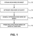
- FIG. 1 is a flow diagram that illustrates an example technique for forming a bulk Fe 16 N 2 permanent magnet. The technique of FIG. 1 will be described with concurrent reference to FIGS. 2-5 .
- FIG. 2 illustrates a conceptual diagram of an apparatus with which the iron wire or sheet can be strained and exposed to nitrogen.
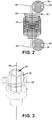
- FIG. 3 illustrates further detail of one example of the Crucible heating stage shown in FIG. 2 .
- iron wire or sheet 28 is formed of a single bcc crystal structure.
- iron wire or sheet 28 may be formed of a plurality of bcc iron crystals.
- the plurality of iron crystals are oriented such that at least some, e.g., a majority or substantially all, of the ⁇ 001> axes of individual unit cells and/or crystals are substantially parallel to the direction in which strain is applied to iron wire or sheet 28.
- the iron is formed as iron wire or sheet 28
- at least some of the ⁇ 001> axes may be substantially parallel to the major axis of the iron wire or sheet 28, as shown in FIGS. 2 and 3 .
- iron wire or sheet 28 may have a crystalline textured structure. Techniques may be used to form crystalline textured (e.g., with desired crystalline orientation along the certain direction of wires and sheets) iron wires or sheet 28.
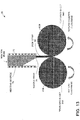
- FIG. 13 is a conceptual diagram illustrating one example apparatus 70 for fast belt casting to texture an example iron wire or sheet, such as iron wire or sheet 28.
- fast belt casting apparatus 70 includes ingot chamber 76 which contains molten iron ingot 72, which may be heated by heating source 74, e.g., in the form of a heating coil. Ingot 72 flow out of chamber 76 through nozzle head 78 to form iron strip 80.
- Iron strip 80 is fed into the gap zone between surface of pinch rollers 82A and 82B, which are rotated in opposite directions.
- the rotation of roller 82A and 82B may vary from approximately 10 to 1000 rotations per minute.
- Iron strip cools on pinch rollers 82A and 82B and, after being pressed between pinch rollers 82A and 82B, forms textured iron strips 84A and 84B.
- texted iron strips 84A and 84B may form textured iron ribbon with thickness between, e.g., about one micrometer and about a millimeter (either individually or after compression of multiple iron strips.
- FIG. 4 is a conceptual diagram that shows eight (8) iron unit cells in a strained state with nitrogen atoms implanted in interstitial spaces between iron atoms.
- the example in FIG. 4 is a conceptual diagram that shows eight (8) iron unit cells in a strained state with nitrogen atoms implanted in interstitial spaces between iron atoms. The example in FIG.
- FIG. 6 is a conceptual diagram illustrating another example apparatus with which iron wire or sheet 28 can be strained as described herein.
- apparatus 54 includes clamps 56 and 58 which may secure opposing ends of iron wire or sheet 28 by tightening screws 60a-d.
- bolt 62 may be turned to rotate the threaded body of bolt 62 to increase the distance between clamps 56 and 58 and exert a tensile force on iron wire or sheet 28.
- apparatus 54 may be placed in a furnace (e.g., a tube furnace) or other heated environment so that iron wire or sheet 28 may be heated during and/or after iron wire or sheet 28 is stretched by apparatus 54.
- a furnace e.g., a tube furnace
- iron wire or sheet 28 may be heated during and/or after iron wire or sheet 28 is stretched by apparatus 54.
- a strain inducing apparatus may strain iron wire or sheet 28 to a certain elongation.
- the strain on iron wire or sheet 28 may be between about 0.3 % and about 7 %. In other examples, the strain on iron wire or sheet 28 may be less than about 0.3% or greater than about 7%.
- exerting a certain strain on iron wire or sheet 28 may result in a substantially similar strain on individual unit cells of the iron, such that the unit cell is elongated along the ⁇ 001> axis between about 0.3 % and about 7 %.
- Iron wire or sheet 28 may have any suitable diameter and/or thickness.
- a suitable diameter and/or thickness may be on the order of micrometers ( ⁇ m) or millimeters (mm).
- an iron wire may have a diameter greater than about 10 ⁇ m (0.01 mm).
- the iron wire has a diameter between about 0.01 mm and about 1 mm, such as about 0.1 mm.
- an iron sheet may have any suitable thickness and/or width.
- the iron sheet may have a thickness greater than about 0.01 mm, such as between about 0.01 mm and about 1 mm, or about 0.1 mm.
- a width of the iron sheet may be greater than a thickness of the iron sheet.
- a diameter of the iron wire or cross-sectional area of the iron sheet may affect an amount of force that must be applied to iron wire or sheet 28 to result in a given strain.
- the application of approximately 144 N of force to an iron wire with a diameter of about 0.1 mm may result in about a 7 % strain.
- the application of approximately 576 N of force to an iron wire with a diameter of about 0.2 mm may result in about a 7 % strain.
- the application of approximately 1296 N of force to an iron wire with a diameter of about 0.3 mm may result in about a 7 % strain.
- the application of approximately 2304 N of force to an iron wire with a diameter of about 0.4 mm may result in about a 7 % strain.
- the application of approximately 3600 N of force to an iron wire with a diameter of about 0.5 mm may result in about a 7 % strain.
- iron wire or sheet 28 may include dopant elements which serve to stabilize the Fe 16 N 2 phase constitution once the Fe 16 N 2 phase constitution has been formed.
- the phase stabilization dopant elements may include cobalt (Co), titanium (Ti), copper (Cu), zinc (Zn), or the like.
- iron wire or sheet 28 may be nitridized (14). In some examples, during the nitridization process, iron wire or sheet 28 may be heated using a heating apparatus.
- a heating apparatus that can be used to heat iron wire or sheet 28 is Crucible heating stage 26, shown in FIGS. 2 and 3 .
- Crucible heating stage 26 defines aperture 30 through which iron wire or sheet 28 passes (e.g., in which a portion of iron wire or sheet 28 is disposed). In some examples, no portion of Crucible heating stage 26 contacts iron wire or sheet 28 during the heating of iron wire or sheet 28. In some implementations, this is advantageous as it lower a risk of unwanted elements or chemical species contacting and diffusing into iron wire or sheet 28. Unwanted elements or chemical species may affect properties of iron wire or sheet 28; thus, it may be desirable to reduce or limit contact between iron wire or sheet 28 and other materials.
- Crucible heating stage 26 also includes an inductor 32 that surrounds at least a portion of aperture 30 defined by Crucible heating stage 26.
- Inductor 32 includes an electrically conductive material, such as aluminum, silver, or copper, through which an electric current may be passed. The electric current may by an alternating current (AC), which may induce eddy currents in iron wire or sheet 28 and heat the iron wire or sheet 28.
- AC alternating current
- other non-contact heating sources may be used instead of using Crucible heating stage 26 to heat iron wire or sheet 28.
- a radiation heat source such as an infrared heat lamp, may be used to heat iron wire or sheet 28.
- a plasma arc lamp may be used to heat iron wire or sheet 28.
- the heating apparatus may heat iron wire or sheet 28 to temperature for a time sufficient to allow diffusion of nitrogen to a predetermined concentration substantially throughout the thickness or diameter of iron wire or sheet 28.
- the heating time and temperature are related, and may also be affected by the composition and/or geometry of iron wire or sheet 28.
- iron wire or sheet 28 may be heated to a temperature between about 125°C and about 600°C for between about 2 hours and about 9 hours.
- iron wire or sheet 28 may be heated to a temperature between about 500°C and about 600°C for between about 2 hours and about 4 hours.
- iron wire or sheet 28 includes an iron wire with a diameter of about 0.1 mm.
- iron wire or sheet 28 may be heated to a temperature of about 125°C for about 8.85 hours or a temperature of about 600°C for about 2.4 hours.
- the nitridizing process time may be inversely proportional to a characteristic dimension squared of iron wire or sheet 28, such as a diameter of an iron wire or a thickness of an iron sheet.
- nitridizing iron wire or sheet 28 includes exposing iron wire or sheet 28 to an atomic nitrogen substance, which diffuses into iron wire or sheet 28.
- the atomic nitrogen substance may be supplied as diatomic nitrogen (N 2 ), which is then separated (cracked) into individual nitrogen atoms.
- the atomic nitrogen may be provided from another atomic nitrogen precursor, such as ammonia (NH3).
- the atomic nitrogen may be provided from urea (CO(NH 2 ) 2 ).
- the nitrogen precursor (e.g., N 2 or NH3) may be cracked to form atomic nitrogen substances using a variety of techniques.
- the nitrogen precursor may be heated using radiation to crack the nitrogen precursor to form atomic nitrogen substances and/or promote reaction between the nitrogen precursor and iron wire or sheet 28.
- a plasma arc lamp may be used to split the nitrogen precursor to form atomic nitrogen substances and/or promote reaction between the nitrogen precursor and iron wire or sheet 28.
- iron wire or sheet 28 may be nitridized (14) via a urea diffusion process, in which urea is utilized as a nitrogen source (e.g., rather than diatomic nitrogen or ammonia).
- Urea also referred to as carbamide
- CO(NH 2 ) 2 is an organic compound with the chemical formula CO(NH 2 ) 2 that may be used in some cases as a nitrogen release fertilizer.
- urea may heated, e.g., within a furnace with iron wire or sheet 28, to generate decomposed nitrogen atoms which may diffuse into iron wire or sheet 28.
- the constitution of the resulting nitridized iron material may controlled to some extent by the temperature of the diffusion process as well as the ratio (e.g., the weight ratio) of iron to urea used for the process.
- iron wire or sheet 28 may be nitridized by an implantation process similar to that used in semiconductor processes for introducing doping agents.
- FIG. 7 is a schematic diagram illustrating an example apparatus 64 that may be used for nitriding iron wire or sheet 28 via a urea diffusion process.
- a urea diffusion process may be used to nitriding iron wire or sheet 28, e.g., when having a single crystal iron, a plurality of crystal structure, or textured structure.
- iron materials with different shapes, such as wire, sheet or bulk can also be diffused using such a process.
- the wire diameter may be varied, e.g., from several micrometers to millimeters.
- the sheet thickness may be from, e.g., several nanometers to millimeters.
- the material weight may be from, e.g., about 1 milligram to kilograms.
- apparatus 64 includes crucible 66 within vacuum furnace 68. Iron wire or sheet 28 is located within crucible 66 along with the nitrogen source of urea 72. As shown in FIG. 7 , a carrier gas including Ar and hydrogen is fed into crucible 66 during the urea diffusion process. In other examples, a different carrier gas or even no carrier gas may be used.
- the gas flow rate within vacuum furnace 68 during the urea diffusion process may be between approximately 5 standard cubic centimeters per minute (sccm) to approximately 50 sccm, such as, e.g., 20 standard cubic centimeters per minute (sccm) to approximately 50 sccm or 5 standard cubic centimeters per minute (sccm) to approximately 20 sccm.
- Heating coils 70 may heat iron wire or sheet 28 and urea 72 during the urea diffusion process using any suitable technique, such as, e.g., eddy current, inductive current, radio frequency, and the like.
- Crucible 66 may be configured to withstand the temperature used during the urea diffusion process. In some examples, crucible 66 may be able to withstand temperatures up to approximately 1600°C.
- the temperature of urea 72 and iron wire or sheet 28 may be between, e.g., approximately 200°C and approximately 150°C to anneal the iron and nitrogen mixture to form an iron nitride material having a Fe 16 N 2 phase constitution substantially throughout the thickness or diameter of iron wire or sheet 28.
- Urea 72 and iron wire or sheet 28 may be at the annealing temperature, e.g., between approximately 1 hour and approximately 40 hours. Such an annealing process could be used in addition to or as an alternative to other nitrogen diffusion techniques, e.g., when the iron material is single crystal iron wire and sheet, or textured iron wire and sheet with thickness in micrometer level.
- nitrogen may diffuse into iron wire or sheet 28 from the nitrogen gas or gas mixture including Ar plus hydrogen carrier gas within furnace 68.
- gas mixture may have a composition of approximately 86% Ar + 4%H 2 + 10%N 2 .
- the gas mixture may have a composition of 10%N 2 + 90%Ar or 100%N 2 or 100%Ar.
- the constitution of the iron nitride material formed via the urea diffusion process may be dependent on the weight ratio of urea to iron used.
- the weight ratio of urea to iron may be selected to form an iron nitride material having a Fe 16 N 2 phase constitution.
- such a urea diffusion process may be used to form iron nitride materials other than that having a Fe 16 N 2 phase constitution, such as, e.g., Fe 2 N, Fe 3 N, Fe 4 N, FesN, and the like.
- the urea diffusion process may be used to diffuse nitrogen into materials other than iron.
- such an urea diffusion process may be used to diffuse nitrogen into there are Indium, FeCo, FePt, CoPt, Cobalt, Zn, Mn, and the like.
- the nitrogen may be diffused into iron wire or sheet 28 to a concentration of about 8 atomic percent (at. %) to about 14 at. %, such as about 11 at. %.
- the concentration of nitrogen in iron may be an average concentration, and may vary throughout the volume of iron wire or sheet 28.
- the resulting phase constitution of at least a portion of the nitridized iron wire or sheet 28 (after nidtridizing iron wire or sheet 28 (14)) may be ⁇ ' phase FesN.
- the FesN phase constitution is the chemically disordered counterpart of chemically-ordered Fe 16 N 2 phase.
- a FesN phase constitution is also has a bct crystal cell, and can introduce a relatively high magnetocrystalline anisotropy.
- the nitridized iron wire or sheet 28 may be ⁇ " phase Fe 16 N 2 .
- FIG. 8 is an iron nitrogen phase diagram. As indicated in FIG. 8 , at an atomic percent of approximately 11 at. % N, ⁇ " phase Fe 16 N 8 may be formed by quenching an Fe-N mixture at a temperature above approximately 650°C for a suitable amount of time. Additionally, at an atomic percent of approximately 11 at. % N, ⁇ " phase Fe 16 N 8 may be formed by annealing an Fe-N mixture at a temperature below approximately 200°C for a suitable amount of time
- iron wire or sheet 28 may be annealed at a temperature for a time to facilitate diffusion of the nitrogen atoms into appropriate interstitial spaces within the iron lattice to form Fe 16 N 2 (16).
- FIG. 4 illustrates an example of the appropriate interstitial spaces of the iron crystal lattice in which nitrogen atoms are positioned.
- the nitridized iron wire or sheet 28 may be annealed at a temperature between about 100°C and about 300°C. In other examples, the annealing temperature may be about 126.85°C (about 400 Kelvin).
- the nitridized iron wire or sheet 28 may be annealed using Crucible heating stage 26, a plasma arc lamp, a radiation heat source, such as an infrared heat lamp, an oven, or a closed retort.
- the annealing process may continue for a predetermined time that is sufficient to allow diffusion of the nitrogen atoms to the appropriate interstitial spaces. In some examples, the annealing process continues for between about 20 hours and about 100 hours, such as between about 40 hours and about 60 hours. In some examples, the annealing process may occur under an inert atmosphere, such as Ar, to reduce or substantially prevent oxidation of the iron. In some implementations, while iron wire or sheet 28 is annealed (16) the temperature is held substantially constant.
- iron wire or sheet 28 may include a Fe 16 N 2 phase constitution.
- at least a portion of iron wire or sheet 28 consists essentially of a Fe 16 N 2 phase constitution.
- iron wire or sheet 28 includes Fe 16 N 2 and other materials that do not materially affect the basic and novel characteristics of the Fe 16 N 2 phase.
- iron wire or sheet 28 may include a Fe 16 N 2 phase constitution and a FesN phase constitution, e.g., in different portions of iron wire or sheet 28.
- FesN phase constitution and Fe 16 N 2 phase constitution in the wires and sheets and the later their pressed assemble may exchange-couple together magnetically through a working principle of quantum mechanics. This mayl form a so-called exchange-spring magnet, which may increase the magnetic energy product even just with a small portion of Fe 16 N.
- iron wire or sheet 28 may include dopant elements or defects that serve as magnetic domain wall pinning sites, which may increase coercivity of iron wire or sheet 28.
- an iron wire or sheet 28 that consists essentially of Fe 16 N 2 phase constitution may include dopants or defects that serve as domain wall pinning sites.
- iron wire or sheet 28 may include non magnetic dopant elements that serve as grain boundaries, which may increase coercivity of iron wire or sheet.
- an iron wire or sheet 28 that consists of Fe 16 N 2 phase constitution may include non magnetic elements that serve as grain boundaries.
- iron wire or sheet 28 may be cooled under an inert atmosphere, such as argon, to reduce or prevent oxidation.
- iron wire or sheet 28 may not be a sufficient size for the desired application.
- multiple iron wire or sheets 28 may be formed (each including or consisting essentially of a Fe 16 N 2 phase constitution) and the multiple iron wire or sheets 28 may be pressed together to form a larger permanent magnet that includes or consists essentially of a Fe 16 N 2 phase constitution (18).
- the multiple iron wires or sheets 28 may be compressed using, for example, cold compression or hot compression.
- the temperature at which the compression is performed may be below about 300°C, as Fe 16 N 2 may begin to degrade above about 300°C.
- the compression may be performed at a pressure and for a time sufficient to join the multiple iron wires or sheets 28 into a substantially unitary permanent magnet 52, as shown in FIG. 5B .
- permanent magnet 52 has a size in at least one dimension of at least 0.1 mm. In some examples, permanent magnet 52 has a size in at least one dimension of at least 1 mm. In some examples, permanent magnet 52 has a size in at least one dimension of at least 1 cm.
- magnetic domain wall pinning sites may be formed by introducing defects into the iron crystal lattice.
- the defects may be introduced by injecting a dopant element into the iron crystal lattice or through mechanical stress of the iron crystal lattice.
- the defects may be introduced into the iron crystal lattice before introduction of nitrogen and formation of the Fe 16 N 2 phase constitution.
- the defects may be introduced after annealing iron wire or sheet 28 to form Fe 16 N 2 (16).
- defects that serve as domain wall pinning sites may be introduced into iron wire or sheet 28 may be ion bombardment of boron (B), copper (Cu), carbon (C), silicon (Si), or the like, into the iron crystal lattice.
- powders consisting of non magnetic elements or compounds e.g. Cu, Ti, Zr, Ta, SiO 2 , Al 2 O 3 , etc
- Those non magnetic powders, with the size ranging from several nanometers to several hundred nanometers function as the grain boundaries for Fe 16 N 2 phase after pressing process. Those grain boundaries may enhance the coercivity of the permanent magnet.
- one or more of the examples processes describe herein may also apply to FeCo alloy to form single crystal or highly textured FeCo wires and sheets. Co atoms may replace part of Fe atoms in Fe lattice to enhance the magnetocrystalline anisotropy. Additionally, one or more of the examples strained diffusion processes described herein may also apply to these FeCo wires and sheets. Furthermore, one or more of the examples processes may also apply to diffuse Carbon (C), Boron (B) and Phosphorus (P) atoms into Fe or FeCo wires and sheets, or partially diffuse C, P, B into Fe or FeCo wires and sheets together with N atoms.
- C Carbon
- B Boron
- the methods described herein may also apply to FeCo alloy to form single crystal or highly textured FeCo wires and sheets.
- Co atoms may replace part of Fe atoms in Fe lattice, e.g., to enhance the magnetocrystalline anisotropy.
- the method described herein may also apply to diffuse Carbon (C), Boron (B) and Phosphorus (P) atoms into Fe or FeCo wires and sheets, or partially diffuse C, P, B into Fe or FeCo wires and sheets together with N atoms.
- the iron used for the processes described herein may take the shape of wire, sheet, or bulk form.
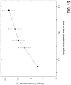
- FIG. 12 is plot of weight ratio of urea to bulk iron material used in the urea diffusion process versus nitrogen concentration (at. %) of the final iron nitride material. As noted above, ratios of 0.5 (i.e., 1:2), 1.0, 1.2, 1.6, and 2.0 for urea to bulk iron material where used. As shown in FIG. 12 , different weight ratios of urea to iron may lead to different nitrogen concentrations within the iron nitride material following urea diffusion. In particular, FIG. 12 illustrates that the atomic ratio of nitrogen in the iron nitride material increased as the amount of urea used relative to the amount bulk iron increased. Accordingly, in at least some cases, the desired nitrogen concentration of an iron nitride material formed via urea diffusion may be obtained by using the weight ratio of urea to iron in the starting material corresponding to the desired nitrogen concentration.
- FIG. 10 is plot of depth below the surface of the iron nitride material versus concentration (at. %) for the iron nitride material formed via urea diffusion starting with a weight ratio of urea to iron of approximately 2.0. As shown in FIG. 10 , the concentration of nitrogen from the surface of the iron nitride material to approximately 1600 angstroms below the surface of the material was approximately 6 at. %. Moreover, there isn't any trace for oxygen and carbon, which means that other dopant source(s) have been diminished effectively.
- FIG. 11 is a plot of depth below the surface of the iron nitride material versus concentration (at. %) for the iron nitride material formed via urea diffusion starting with a weight ratio of urea to iron of approximately 1.0.
- concentration of nitrogen from the surface of the iron nitride material to approximately 800 angstroms below the surface of the material was approximately 6 -12 at. %.
- the concentration could be reduced further by improving the vacuum system, e.g., such as using pumping system to cause greater flow.
- oxygen has been diminished to be about 4 at. %.
- there is over 10 at. % carbon since it can be considered a substitute element for nitrogen, it has no significant negative effect on the fabricated permanent magnet.
- One example method comprises straining an iron wire or sheet comprising at least one iron crystal in a direction substantially parallel to a ⁇ 001> crystal axis of the iron crystal to distort a unit cell structure of the at least one iron crystal and form a distorted unit cell structure having an increased length along the ⁇ 001> crystal axis.
- the method further comprises nitridizing the iron wire or sheet to form a nitridized iron wire or sheet, and annealing the nitridized iron wire or sheet to form a Fe16N2 phase constitution at least a portion of the nitridized iron wire or sheet.
- straining the iron wire or sheet comprising the at least one iron crystal in the direction substantially parallel to the ⁇ 001> crystal axis of the iron crystal may comprise applying a tensile force to the iron wire or sheet by pulling a first end of the iron wire or sheet in a first direction and pulling the second end of the iron wire or sheet in a second direction substantially opposite to the first direction.
- nitridizing the iron wire or sheet to form the nitridized iron wire or sheet may comprise exposing the iron wire or sheet to an atomic nitrogen substance.
- the nitrogen precursor may be mixed with a carrier gas.
- the nitrogen precursor may be mixed with the carrier gas to a partial pressure of between about 0.02 and about 0.1.
- exposing the iron wire or sheet to the atomic nitrogen substance may comprise exposing the iron wire or sheet to a nitrogen precursor at a pressure between about 0.133 Pa and about 1333 Pa.
- annealing the nitridized iron wire or sheet to form the Fe 16 N 2 phase constitution in at least the portion of the nitridized iron wire or sheet may comprise heating the nitridized iron wire or sheet to between about 100°C and about 300°C for between about 20 hours and about 100 hours.
- annealing the nitridized iron wire or sheet to form the Fe 16 N 2 phase constitution in at least the portion of the nitridized iron wire or sheet may comprise annealing the nitridized iron wire or sheet under an inert atmosphere.
- the example method may further comprise compressing a plurality of nitridized iron wires or sheets comprising a Fe 16 N 2 phase constitution to form a permanent magnet comprising a Fe 16 N 2 phase constitution.
- compressing the plurality of nitridized iron wires or sheets may comprise the Fe 16 N 2 phase constitution to form the permanent magnet comprising the Fe 16 N 2 phase constitution comprises cold compressing the plurality of nitridized iron wires or sheets comprising the Fe 16 N 2 phase constitution to form the permanent magnet comprising the Fe 16 N 2 phase constitution.
- compressing the plurality of nitridized iron wires or sheets comprising the Fe 16 N 2 phase constitution to form the permanent magnet comprising the Fe 16 N 2 phase constitution may comprise substantially aligning a ⁇ 001> crystal axis of a first nitridized iron wire or sheet comprising the Fe 16 N 2 phase constitution with a ⁇ 001> crystal axis of a second nitridized iron wire or sheet comprising the Fe 16 N 2 phase constitution prior to compressing the first nitridized iron wire or sheet and the second iron wire or sheet.
- compressing the plurality of nitridized iron wires or sheets comprising the Fe 16 N 2 phase constitution to form the permanent magnet comprising the Fe 16 N 2 phase constitution may comprise compressing the plurality of nitridized iron wires or sheets comprising the Fe 16 N 2 phase constitution to form the permanent magnet comprising the Fe 16 N 2 phase constitution and defining a size in at least one dimension of at least 0.1 mm.
- compressing the plurality of nitridized iron wires or sheets comprising the Fe 16 N 2 phase constitution to form the permanent magnet comprising the Fe 16 N 2 phase constitution may comprise compressing the plurality of nitridized iron wires or sheets comprising the Fe 16 N 2 phase constitution to form the permanent magnet comprising the Fe 16 N 2 phase constitution and defining a size in at least one dimension of at least 1 mm.
- introducing magnetic domain wall pinning sites into the nitridized iron wire or sheet may comprise ion bombarding the nitridized iron wire or sheet with a dopant element.
- a system comprises a strain inducing apparatus configured to exert a strain on an iron wire or sheet comprising at least one body centered cubic (bcc) iron crystal in a direction substantially parallel to a ⁇ 001> axis of the bcc iron crystal, a first heating apparatus configured to heat the strained iron wire or sheet, a source of an atomic nitrogen substance configured to expose the strained iron wire or sheet to the atomic nitrogen substance to form a nitridized iron wire or sheet, and a second heating apparatus configured to heat the nitridized iron wire or sheet to a temperature sufficient to anneal the nitridized iron wire or sheet to form a Fe 16 N 2 phase constitution in at least a portion of the nitridized iron wire or sheet.
- bcc body centered cubic
- the example system may further comprises a press configured to compress a plurality of nitridized iron wire or sheets comprising a Fe 16 N 2 phase constitution to form a substantially unitary permanent magnet including a Fe 16 N 2 phase constitution.
- the press may be configured to compress a plurality of nitridized iron wires or sheets comprising the Fe 16 N 2 phase constitution to form a substantially unitary permanent magnet including the Fe 16 N 2 phase constitution and defining a size in at least one dimension of at least 0.1 mm.
- the press may be configured to compress a plurality of nitridized iron wires or sheets comprising the Fe 16 N 2 phase constitution to form a substantially unitary permanent magnet including the Fe 16 N 2 phase constitution and defining a size in at least one dimension of at least 1 mm.
- the source of the atomic nitrogen substance may comprise urea.
- the example system may further comprise means for introducing magnetic domain wall pinning sites into the nitridized iron wire or sheet.
- the strain inducing apparatus may comprise a first roller configured to receive a first end of the iron wire or sheet and a second roller configured to receive a second end of the iron wire or sheet, wherein the second end is substantially opposite the first end, and wherein the first roller and the second roller are configured to rotate to apply a tensile force between the first end of the iron wire or sheet and the second end of the iron wire or sheet.
- the first roller and the second roller are configured to rotate to strain the iron wire or sheet between about 0.3% and about 7.0%.
- the first heating apparatus may comprise, for example, a crucible heating stage, a radiation heat source or a plasma arc lamp.
- the second heating apparatus may comprise, for example, a heating crucible, radiation heat source, a plasma arc lamp, an oven or a closed retort.
- the wire may have an energy product of greater than about 239kJm -3 (30 MGOe). In other examples, the wire has an energy product of greater than about 477kJm -3 (60 MGOe). In other examples, the wire has an energy product of greater than about 517kJm -3 (65 MGOe). In other examples, the wire has an energy product of greater than about 796kJm -3 (100 MGOe). In other examples, the wire has an energy product of between about 477kJm -3 (60 MGOe) and about 1074kJm -3 (135 MGOe).
- the wire defines a major axis extending from a first end of the wire to a second end of the wire, wherein the wire comprises at least one body centered tetragonal (bct) iron nitride crystal, and wherein a ⁇ 001> axis of the at least one bct iron nitride crystal is substantially parallel to the major axis of the wire.
- bct body centered tetragonal
- the example permanent magnet may further comprise a phase stabilization dopant element comprising at least one of Ti, Co, Ti, Ta, Ni, Mn, Zr, Mo, Nb, Nd, Ga, Ge, C, B, Si, P, Cr, Cu, or Zn.
- a phase stabilization dopant element comprising at least one of Ti, Co, Ti, Ta, Ni, Mn, Zr, Mo, Nb, Nd, Ga, Ge, C, B, Si, P, Cr, Cu, or Zn.
- the wire of the permanent magnet comprises a FesN phase constitution. In another example, the wire of the permanent magnet consists essentially of the Fe 16 N 2 phase constitution.
- the sheet may have an energy product of greater than about 239kJm -3 (30 MGOe). In other examples, the sheet may have an energy product of greater than about 477kJm -3 (60 MGOe). In other examples, the sheet has an energy product of greater than about 517kJm -3 (65 MGOe). In other examples, the sheet has an energy product of greater than about 796kJm -3 (100 MGOe). In other examples, the sheet has an energy product of between about 477kJm -3 (60 MGOe) and about 1074kJm -3 (135 MGOe).
- the sheet defines a major axis extending from a first end of the sheet to a second end of the sheet, wherein the sheet comprises at least one body centered tetragonal (bct) iron nitride crystal, and wherein a ⁇ 001> axis of the at least one bct iron nitride crystal is substantially parallel to the major axis of the sheet.
- bct body centered tetragonal
- the sheet further comprises a FesN phase constitution.
- the sheet consists essentially of the Fe 16 N 2 phase constitution.
- the permanent magnet may have an energy product of greater than about 239kJm -3 (30 MGOe). In other examples, the permanent magnet may have an energy product of greater than about 477kJm -3 (60 MGOe). In other examples, the permanent magnet may have an energy product of greater than about 517kJm -3 (65 MGOe). In other examples, the permanent magnet may have an energy product of greater than about 796kJm -3 (100 MGOe). In other examples, the permanent magnet may have an energy product of between about 477kJm -3 (60 MG ⁇ Oe) and about 1074kJm -3 (135 MG ⁇ Oe).
- the permanent magnet may comprises a FesN phase constitution.
- the permanent magnet consists essentially of the Fe 16 N 2 phase constitution.
- Another example method comprises nitridizing a metallic member via a urea diffusion process.
- the metallic member may comprise iron.
- the metallic member consists essentially of iron.
- a ratio of urea to iron is selective such that, after the urea diffusion process, the metallic member consists essentially of the Fe 16 N 2 phase constitution.
Landscapes
- Engineering & Computer Science (AREA)
- Chemical & Material Sciences (AREA)
- Power Engineering (AREA)
- Mechanical Engineering (AREA)
- Organic Chemistry (AREA)
- Materials Engineering (AREA)
- Metallurgy (AREA)
- Manufacturing & Machinery (AREA)
- Chemical Kinetics & Catalysis (AREA)
- Physics & Mathematics (AREA)
- Crystallography & Structural Chemistry (AREA)
- Thermal Sciences (AREA)
- Electromagnetism (AREA)
- Hard Magnetic Materials (AREA)
- Manufacturing Cores, Coils, And Magnets (AREA)
- Solid-Phase Diffusion Into Metallic Material Surfaces (AREA)
- Permanent Field Magnets Of Synchronous Machinery (AREA)
- Heat Treatment Of Articles (AREA)
- Manufacturing Of Steel Electrode Plates (AREA)
Applications Claiming Priority (2)
| Application Number | Priority Date | Filing Date | Title |
|---|---|---|---|
| US201161524423P | 2011-08-17 | 2011-08-17 | |
| PCT/US2012/051382 WO2013026007A2 (en) | 2011-08-17 | 2012-08-17 | Iron nitride permanent magnet and technique for forming iron nitride permanent magnet |
Publications (2)
| Publication Number | Publication Date |
|---|---|
| EP2745298A2 EP2745298A2 (en) | 2014-06-25 |
| EP2745298B1 true EP2745298B1 (en) | 2019-12-11 |
Family
ID=46924533
Family Applications (1)
| Application Number | Title | Priority Date | Filing Date |
|---|---|---|---|
| EP12762709.9A Active EP2745298B1 (en) | 2011-08-17 | 2012-08-17 | Technique and system for forming iron nitride permanent magnet |
Country Status (10)
| Country | Link |
|---|---|
| US (4) | US10068689B2 (enExample) |
| EP (1) | EP2745298B1 (enExample) |
| JP (3) | JP6085301B2 (enExample) |
| KR (1) | KR20140072047A (enExample) |
| CN (2) | CN107103975B (enExample) |
| AU (2) | AU2012296365B2 (enExample) |
| BR (1) | BR112014003539A2 (enExample) |
| CA (1) | CA2851222A1 (enExample) |
| IL (1) | IL230806A0 (enExample) |
| WO (1) | WO2013026007A2 (enExample) |
Families Citing this family (20)
| Publication number | Priority date | Publication date | Assignee | Title |
|---|---|---|---|---|
| JP6085301B2 (ja) | 2011-08-17 | 2017-02-22 | リージェンツ オブ ザ ユニバーシティ オブ ミネソタ | 窒化鉄永久磁石および窒化鉄永久磁石の形成技術 |
| WO2013042721A1 (ja) * | 2011-09-22 | 2013-03-28 | 戸田工業株式会社 | 強磁性窒化鉄粒子粉末の製造方法、異方性磁石、ボンド磁石及び圧粉磁石 |
| WO2014124135A2 (en) | 2013-02-07 | 2014-08-14 | Regents Of The University Of Minnesota | Iron nitride permanent magnet and technique for forming iron nitride permanent magnet |
| KR101821344B1 (ko) * | 2013-06-27 | 2018-01-23 | 리전츠 오브 더 유니버시티 오브 미네소타 | 질화철 재료 및 질화철 재료를 포함하는 자석 |
| CN106165027A (zh) * | 2014-03-28 | 2016-11-23 | 明尼苏达大学董事会 | 包含涂覆的纳米颗粒的氮化铁磁性材料 |
| US9994949B2 (en) | 2014-06-30 | 2018-06-12 | Regents Of The University Of Minnesota | Applied magnetic field synthesis and processing of iron nitride magnetic materials |
| US10072356B2 (en) | 2014-08-08 | 2018-09-11 | Regents Of The University Of Minnesota | Magnetic material including α″-Fe16(NxZ1-x)2 or a mixture of α″-Fe16Z2 and α″-Fe16N2, where Z includes at least one of C, B, or O |
| BR112017002464A2 (pt) | 2014-08-08 | 2017-12-05 | Univ Minnesota | formação de materiais magnéticos rígidos de nitreto de ferro utilizando deposição química de vapor ou epitaxia em fase líquida |
| EP3178099A4 (en) * | 2014-08-08 | 2018-04-18 | Regents of the University of Minnesota | Multilayer iron nitride hard magnetic materials |
| US10002694B2 (en) | 2014-08-08 | 2018-06-19 | Regents Of The University Of Minnesota | Inductor including alpha″-Fe16Z2 or alpha″-Fe16(NxZ1-x)2, where Z includes at least one of C, B, or O |
| CN107408434A (zh) | 2015-01-26 | 2017-11-28 | 明尼苏达大学董事会 | 应用磁场合成和处理氮化铁磁性材料 |
| CN107396631A (zh) | 2015-01-26 | 2017-11-24 | 明尼苏达大学董事会 | 具有各向异性形状的铁氮化物粉末 |
| JP6631029B2 (ja) * | 2015-04-21 | 2020-01-15 | Tdk株式会社 | 永久磁石、及び、それを備えた回転機 |
| JP6332359B2 (ja) * | 2015-10-14 | 2018-05-30 | 株式会社デンソー | FeNi規則合金、FeNi規則合金の製造方法、および、FeNi規則合金を含む磁性材料 |
| CN110073448B (zh) | 2016-10-07 | 2021-10-15 | 明尼苏达大学董事会 | 铁基纳米颗粒和晶粒 |
| WO2018204800A1 (en) * | 2017-05-04 | 2018-11-08 | Regents Of The University Of Minnesota | Iron nitride compositions |
| KR20200032670A (ko) * | 2017-05-08 | 2020-03-26 | 알파 링 인터네셔널, 엘티디. | 상호 작용하는 반응물에 대한 쿨롱 장벽 감소 |
| WO2020111386A1 (ko) * | 2018-11-30 | 2020-06-04 | 한양대학교 에리카산학협력단 | 질화철 자성 와이어 및 그 제조방법 |
| JP7325964B2 (ja) * | 2019-01-11 | 2023-08-15 | 株式会社東芝 | 電磁波減衰体及び電子装置 |
| US12018386B2 (en) | 2019-10-11 | 2024-06-25 | Regents Of The University Of Minnesota | Magnetic material including α″-Fe16(NxZ1-x)2 or a mixture of α″-Fe16Z2 and α″-Fe16N2, where Z includes at least one of C, B, or O |
Family Cites Families (93)
| Publication number | Priority date | Publication date | Assignee | Title |
|---|---|---|---|---|
| JPS61143557A (ja) | 1984-12-18 | 1986-07-01 | Kawasaki Steel Corp | 飽和磁気モ−メントが高い磁性材料 |
| JPS61157634A (ja) | 1984-12-28 | 1986-07-17 | Kawasaki Steel Corp | 高い飽和磁化を有する高けい素鋼薄帯の製造方法 |
| JPS62232101A (ja) | 1986-04-02 | 1987-10-12 | Hitachi Ltd | 窒化鉄磁性体の製造方法 |
| JPS62297437A (ja) | 1986-06-18 | 1987-12-24 | Kawasaki Steel Corp | 飽和磁気モ−メントが高い磁性材料 |
| JPS63132701A (ja) * | 1986-11-25 | 1988-06-04 | Kawasaki Steel Corp | 塗装用鋼板とその製法 |
| JPH0696947B2 (ja) * | 1988-02-08 | 1994-11-30 | 株式会社大林組 | シールド掘進機 |
| JPH01261803A (ja) | 1988-04-12 | 1989-10-18 | Matsushita Electric Ind Co Ltd | 希土類永久磁石の製造方法 |
| US5068147A (en) | 1988-04-28 | 1991-11-26 | Matsushita Electric Industrial Co., Ltd. | Soft magnetic thin film comprising alternate layers of iron carbide with either iron, iron nitride or iron carbon-nitride |
| EP0362812B1 (en) | 1988-10-04 | 1996-01-24 | Hitachi Metals, Ltd. | Bonded isotropic R-Fe-B-magnet and method for making it |
| JP2698407B2 (ja) | 1988-12-26 | 1998-01-19 | 川崎製鉄株式会社 | 方向性けい素鋼板製造過程における冷間圧延方法 |
| JP2665365B2 (ja) * | 1989-02-14 | 1997-10-22 | 三菱製鋼株式会社 | 高い磁性を有する窒化鉄の製造方法 |
| US5032947A (en) | 1989-07-12 | 1991-07-16 | James C. M. Li | Method of improving magnetic devices by applying AC or pulsed current |
| JPH03100124A (ja) | 1989-09-13 | 1991-04-25 | Nippon Steel Corp | 表面品質の優れたCr―Ni系ステンレス鋼薄板の製造方法 |
| DE4025277A1 (de) | 1990-08-09 | 1992-02-13 | Siemens Ag | Verfahren zur herstellung eines anisotropen magnetmaterials auf basis des stoffsystems sm-fe-n |
| JPH04217305A (ja) | 1990-12-19 | 1992-08-07 | Nkk Corp | 窒化鉄系高密度焼結体の製造方法 |
| JP2700043B2 (ja) | 1991-04-16 | 1998-01-19 | 沖電気工業株式会社 | 磁気記録媒体 |
| US5330554A (en) | 1991-08-30 | 1994-07-19 | Aisin Seiki Kabushiki Kaisha | Method for producing iron-nitride powders |
| JP2790395B2 (ja) | 1992-03-25 | 1998-08-27 | 川崎製鉄株式会社 | アパーチャーグリル用鋼板の製造方法 |
| JP3021957B2 (ja) * | 1992-05-14 | 2000-03-15 | 川崎製鉄株式会社 | 高い飽和磁化を有するFe16N2鉄窒化物の製造方法 |
| JPH05326239A (ja) | 1992-05-18 | 1993-12-10 | Mitsubishi Materials Corp | 高い飽和磁束密度を有するFe−N系またはFe−Si−N系軟磁性粉末の製造方法 |
| JPH0641617A (ja) | 1992-07-21 | 1994-02-15 | Mitsubishi Materials Corp | 高い飽和磁束密度を有するFe−N系またはFe−Si−N系軟磁性粉末の製造方法 |
| JPH0696947A (ja) * | 1992-09-11 | 1994-04-08 | Hitachi Ltd | 薄帯状窒化鉄材料 |
| JPH06267722A (ja) * | 1993-03-10 | 1994-09-22 | Nippon Steel Corp | 磁性材料及びその製造方法 |
| JPH06311390A (ja) | 1993-04-26 | 1994-11-04 | Mitsubishi Electric Corp | 映像信号処理装置 |
| RU2113742C1 (ru) | 1993-07-06 | 1998-06-20 | Сумитомо Спешиал Металз Ко., Лтд. | Материалы r-fe-b постоянных магнитов и способы их получения |
| US6139765A (en) | 1993-11-11 | 2000-10-31 | Seiko Epson Corporation | Magnetic powder, permanent magnet produced therefrom and process for producing them |
| CN1156516A (zh) * | 1994-07-18 | 1997-08-06 | 高桥研 | 磁性薄膜及其制造方法 |
| JP3643215B2 (ja) | 1997-07-04 | 2005-04-27 | 株式会社Neomax | 積層永久磁石の製造方法 |
| US6217672B1 (en) | 1997-09-24 | 2001-04-17 | Yide Zhang | Magnetic annealing of magnetic alloys in a dynamic magnetic field |
| JP3932326B2 (ja) | 1998-05-22 | 2007-06-20 | Dowaエレクトロニクス株式会社 | 窒化鉄磁性材料の製法 |
| EP0994493B1 (en) | 1998-10-14 | 2003-09-10 | Hitachi Metals, Ltd. | R-T-B sintered permanent magnet |
| JP2000176513A (ja) | 1998-12-17 | 2000-06-27 | Nippon Steel Corp | 調質圧延用ロール、調質圧延方法および調質圧延金属板 |
| US6457629B1 (en) | 1999-10-04 | 2002-10-01 | Solidica, Inc. | Object consolidation employing friction joining |
| JP3861276B2 (ja) | 1999-11-04 | 2006-12-20 | セイコーエプソン株式会社 | 冷却ロール、磁石材料の製造方法、薄帯状磁石材料、磁石粉末およびボンド磁石 |
| JP2001176715A (ja) | 1999-12-21 | 2001-06-29 | Toyota Central Res & Dev Lab Inc | 高飽和磁化Fe−N系磁性体 |
| WO2001085368A1 (en) * | 2000-05-09 | 2001-11-15 | Usf Filtration And Separations Group, Inc. | Apparatus and method for drawing continuous fiber |
| JP4531331B2 (ja) | 2000-05-31 | 2010-08-25 | 高橋 研 | 磁性薄膜、その製造方法、その評価方法及びこれを用いた磁気ヘッド、磁気記録装置並びに磁気デバイス |
| JP4000552B2 (ja) | 2000-12-27 | 2007-10-31 | スズキ株式会社 | 窒化鉄薄膜の製造方法 |
| JP2002334695A (ja) | 2001-03-09 | 2002-11-22 | Canon Inc | 二次電池および二次電池の製造方法 |
| JP3558996B2 (ja) | 2001-03-30 | 2004-08-25 | 株式会社東芝 | 磁気抵抗効果素子、磁気ヘッド、磁気再生装置及び磁気記憶装置 |
| US6778358B1 (en) | 2002-05-01 | 2004-08-17 | Western Digital (Fremont), Inc. | Magnetically soft, high saturation magnetization laminates of iron-cobalt-nitrogen and iron-nickel |
| GB0220063D0 (en) | 2002-08-29 | 2002-10-09 | Isis Innovation | Magnetic particle and process for preparation |
| CN1768166A (zh) | 2003-01-29 | 2006-05-03 | Tdk株式会社 | 磁性石榴石单晶膜形成用基板、光学元件及其制造方法 |
| GB2422949B (en) | 2003-02-19 | 2007-05-30 | Hitachi Maxell | Magnetic recording medium |
| JP2004319923A (ja) | 2003-04-21 | 2004-11-11 | Hitachi Maxell Ltd | 窒化鉄系磁性粉末 |
| JP4599574B2 (ja) | 2003-11-27 | 2010-12-15 | Dowaエレクトロニクス株式会社 | 窒化鉄系磁性粉末 |
| EP1548760A3 (en) | 2003-11-27 | 2007-12-26 | DOWA Electronics Materials Co., Ltd. | Iron nitride magnetic powder and method of producing the powder |
| JP4534059B2 (ja) | 2004-03-17 | 2010-09-01 | Dowaエレクトロニクス株式会社 | 窒化鉄系磁性粉末およびその製造法 |
| EP1675133B1 (en) | 2004-12-27 | 2013-03-27 | Shin-Etsu Chemical Co., Ltd. | Nd-Fe-B rare earth permanent magnet material |
| JP2007070669A (ja) | 2005-09-06 | 2007-03-22 | Osaka Univ | 窒化硼素炭素および窒化硼素の成膜方法並びに前記方法で得られた膜、基板、デバイス |
| JP2007273038A (ja) | 2006-03-31 | 2007-10-18 | Fujifilm Corp | 磁気記録媒体 |
| JP2008117855A (ja) | 2006-11-01 | 2008-05-22 | Toyota Motor Corp | ナノコンポジット磁石の製造方法 |
| US7736753B2 (en) | 2007-01-05 | 2010-06-15 | International Business Machines Corporation | Formation of nanostructures comprising compositionally modulated ferromagnetic layers by pulsed ECD |
| US8535634B2 (en) | 2007-05-04 | 2013-09-17 | Advanced Materials Corporation | Iron nitride powders for use in magnetic, electromagnetic, and microelectronic devices |
| JP2008311518A (ja) | 2007-06-15 | 2008-12-25 | Hitachi Maxell Ltd | 窒化鉄系磁性粉末の製造方法、窒化鉄系磁性粉末、及び磁気記録媒体 |
| JP5058889B2 (ja) | 2007-07-03 | 2012-10-24 | 日立マクセル株式会社 | 磁気記録媒体 |
| JP2009088287A (ja) | 2007-09-28 | 2009-04-23 | Fujifilm Corp | 窒化鉄粉末、窒化鉄粉末の製造方法、および磁気記録媒体 |
| US9242295B2 (en) | 2007-12-21 | 2016-01-26 | The Univeristy Of Texas At Arlington | Bulk nanocomposite magnets and methods of making bulk nanocomposite magnets |
| JP2009297437A (ja) | 2008-06-17 | 2009-12-24 | Jms Co Ltd | 医療用熱交換器及びその製造方法並びに人工肺装置 |
| JP4791513B2 (ja) | 2008-08-05 | 2011-10-12 | 日立マクセル株式会社 | 窒化鉄系磁性粉末、及びそれを用いた磁気記録媒体 |
| US8591987B2 (en) | 2009-05-18 | 2013-11-26 | Northrop Grumman Systems Corporation | Multiferroic nanoscale thin film materials, method of its facile syntheses and magnetoelectric coupling at room temperature |
| JP2009259402A (ja) | 2009-08-11 | 2009-11-05 | Hitachi Maxell Ltd | 磁気記録媒体および磁気テープカートリッジ |
| JP5344171B2 (ja) | 2009-09-29 | 2013-11-20 | ミネベア株式会社 | 異方性希土類−鉄系樹脂磁石 |
| JP5130270B2 (ja) | 2009-09-30 | 2013-01-30 | 株式会社日立製作所 | 磁性材料及びそれを用いたモータ |
| JP5769223B2 (ja) | 2009-10-22 | 2015-08-26 | 戸田工業株式会社 | 強磁性粒子粉末及びその製造法、異方性磁石及びボンド磁石 |
| CN102893715B (zh) | 2010-05-10 | 2015-07-01 | 韩国机械研究院 | 宽频电磁波吸收体及其制造方法 |
| US9115425B2 (en) | 2010-10-18 | 2015-08-25 | Electronics And Telecommunications Research Institute | Thin film depositing apparatus |
| JP5831866B2 (ja) | 2011-01-21 | 2015-12-09 | 戸田工業株式会社 | 強磁性粒子粉末及びその製造方法、並びに異方性磁石、ボンド磁石及び圧粉磁石 |
| WO2012131872A1 (ja) | 2011-03-28 | 2012-10-04 | 日立金属株式会社 | 複合軟磁性粉末及びその製造方法、並びにそれを用いた圧粉磁心 |
| US20140132376A1 (en) | 2011-05-18 | 2014-05-15 | The Regents Of The University Of California | Nanostructured high-strength permanent magnets |
| JP2012246174A (ja) | 2011-05-27 | 2012-12-13 | Sumitomo Electric Ind Ltd | 窒化鉄材の製造方法及び窒化鉄材 |
| JP6085301B2 (ja) | 2011-08-17 | 2017-02-22 | リージェンツ オブ ザ ユニバーシティ オブ ミネソタ | 窒化鉄永久磁石および窒化鉄永久磁石の形成技術 |
| US9160079B2 (en) | 2011-09-14 | 2015-10-13 | William N. Carr | Compact multi-band antenna |
| JP5924657B2 (ja) | 2011-09-22 | 2016-05-25 | 戸田工業株式会社 | 強磁性窒化鉄粒子粉末の製造方法、異方性磁石、ボンド磁石及び圧粉磁石 |
| JP6155440B2 (ja) | 2011-09-22 | 2017-07-05 | 戸田工業株式会社 | 強磁性窒化鉄粒子粉末の製造方法、異方性磁石、ボンド磁石及び圧粉磁石の製造方法 |
| WO2013042721A1 (ja) | 2011-09-22 | 2013-03-28 | 戸田工業株式会社 | 強磁性窒化鉄粒子粉末の製造方法、異方性磁石、ボンド磁石及び圧粉磁石 |
| JP5708454B2 (ja) | 2011-11-17 | 2015-04-30 | 日立化成株式会社 | アルコール系溶液および焼結磁石 |
| KR20140113684A (ko) | 2011-12-15 | 2014-09-24 | 케이스 웨스턴 리저브 유니버시티 | 희토류를 함유하지 않은 변환가능 질화물 자석 및 이의 제조방법 |
| WO2014124135A2 (en) | 2013-02-07 | 2014-08-14 | Regents Of The University Of Minnesota | Iron nitride permanent magnet and technique for forming iron nitride permanent magnet |
| KR101821344B1 (ko) | 2013-06-27 | 2018-01-23 | 리전츠 오브 더 유니버시티 오브 미네소타 | 질화철 재료 및 질화철 재료를 포함하는 자석 |
| CN106165027A (zh) | 2014-03-28 | 2016-11-23 | 明尼苏达大学董事会 | 包含涂覆的纳米颗粒的氮化铁磁性材料 |
| JP2015232101A (ja) | 2014-06-11 | 2015-12-24 | 株式会社リコー | ケミカルヒートポンプ用反応材、ケミカルヒートポンプ |
| US9994949B2 (en) | 2014-06-30 | 2018-06-12 | Regents Of The University Of Minnesota | Applied magnetic field synthesis and processing of iron nitride magnetic materials |
| US10002694B2 (en) | 2014-08-08 | 2018-06-19 | Regents Of The University Of Minnesota | Inductor including alpha″-Fe16Z2 or alpha″-Fe16(NxZ1-x)2, where Z includes at least one of C, B, or O |
| EP3178099A4 (en) | 2014-08-08 | 2018-04-18 | Regents of the University of Minnesota | Multilayer iron nitride hard magnetic materials |
| US10072356B2 (en) | 2014-08-08 | 2018-09-11 | Regents Of The University Of Minnesota | Magnetic material including α″-Fe16(NxZ1-x)2 or a mixture of α″-Fe16Z2 and α″-Fe16N2, where Z includes at least one of C, B, or O |
| BR112017002464A2 (pt) | 2014-08-08 | 2017-12-05 | Univ Minnesota | formação de materiais magnéticos rígidos de nitreto de ferro utilizando deposição química de vapor ou epitaxia em fase líquida |
| EP3251131A4 (en) | 2015-01-26 | 2018-06-27 | Regents of the University of Minnesota | Preservation of strain in iron nitride magnet |
| CN107408434A (zh) | 2015-01-26 | 2017-11-28 | 明尼苏达大学董事会 | 应用磁场合成和处理氮化铁磁性材料 |
| CN107396631A (zh) | 2015-01-26 | 2017-11-24 | 明尼苏达大学董事会 | 具有各向异性形状的铁氮化物粉末 |
| JP2024143557A (ja) | 2023-03-30 | 2024-10-11 | ノリタケ株式会社 | インクジェットインク |
| JP2024157634A (ja) | 2023-04-26 | 2024-11-08 | キヤノン株式会社 | 制御装置、光学装置、および制御方法 |
| JP7648821B1 (ja) | 2024-02-29 | 2025-03-18 | 株式会社Lixil | ホームシステム、水栓装置、制御装置、水栓システム、第一サーバ、第二サーバ、消耗品発注方法、消耗品発注プログラム |
-
2012
- 2012-08-17 JP JP2014526250A patent/JP6085301B2/ja active Active
- 2012-08-17 AU AU2012296365A patent/AU2012296365B2/en active Active
- 2012-08-17 KR KR1020147007087A patent/KR20140072047A/ko not_active Withdrawn
- 2012-08-17 BR BR112014003539A patent/BR112014003539A2/pt not_active IP Right Cessation
- 2012-08-17 CN CN201710001267.6A patent/CN107103975B/zh active Active
- 2012-08-17 US US14/238,835 patent/US10068689B2/en active Active
- 2012-08-17 CN CN201280047372.9A patent/CN103827986B/zh active Active
- 2012-08-17 CA CA2851222A patent/CA2851222A1/en not_active Abandoned
- 2012-08-17 WO PCT/US2012/051382 patent/WO2013026007A2/en not_active Ceased
- 2012-08-17 EP EP12762709.9A patent/EP2745298B1/en active Active
-
2014
- 2014-02-04 IL IL230806A patent/IL230806A0/en unknown
-
2016
- 2016-11-16 AU AU2016259359A patent/AU2016259359A1/en not_active Abandoned
-
2017
- 2017-01-23 JP JP2017009353A patent/JP2017122277A/ja active Pending
-
2018
- 2018-06-08 US US16/003,428 patent/US11742117B2/en active Active
-
2019
- 2019-07-11 JP JP2019129517A patent/JP6901157B2/ja active Active
-
2023
- 2023-07-07 US US18/348,830 patent/US12412686B2/en active Active
-
2025
- 2025-08-07 US US19/293,562 patent/US20250364164A1/en active Pending
Non-Patent Citations (1)
| Title |
|---|
| None * |
Also Published As
| Publication number | Publication date |
|---|---|
| IL230806A0 (en) | 2014-03-31 |
| CN103827986B (zh) | 2017-02-15 |
| US20140299810A1 (en) | 2014-10-09 |
| US11742117B2 (en) | 2023-08-29 |
| CN107103975A (zh) | 2017-08-29 |
| KR20140072047A (ko) | 2014-06-12 |
| US20180294078A1 (en) | 2018-10-11 |
| WO2013026007A2 (en) | 2013-02-21 |
| US20250364164A1 (en) | 2025-11-27 |
| BR112014003539A2 (pt) | 2017-03-01 |
| AU2012296365A1 (en) | 2014-02-27 |
| AU2012296365A2 (en) | 2014-06-19 |
| JP2017122277A (ja) | 2017-07-13 |
| AU2016259359A1 (en) | 2016-12-08 |
| US20230352219A1 (en) | 2023-11-02 |
| JP2014529682A (ja) | 2014-11-13 |
| JP6085301B2 (ja) | 2017-02-22 |
| US10068689B2 (en) | 2018-09-04 |
| CN107103975B (zh) | 2020-06-16 |
| WO2013026007A3 (en) | 2013-07-25 |
| AU2012296365B2 (en) | 2016-09-15 |
| JP2020010039A (ja) | 2020-01-16 |
| JP6901157B2 (ja) | 2021-07-14 |
| CA2851222A1 (en) | 2013-02-21 |
| CN103827986A (zh) | 2014-05-28 |
| US12412686B2 (en) | 2025-09-09 |
| EP2745298A2 (en) | 2014-06-25 |
Similar Documents
| Publication | Publication Date | Title |
|---|---|---|
| US12412686B2 (en) | Iron nitride permanent magnet and technique for forming iron nitride permanent magnet | |
| US11581113B2 (en) | Preservation of strain in iron nitride magnet | |
| US11217371B2 (en) | Iron nitride permanent magnet and technique for forming iron nitride permanent magnet |
Legal Events
| Date | Code | Title | Description |
|---|---|---|---|
| PUAI | Public reference made under article 153(3) epc to a published international application that has entered the european phase |
Free format text: ORIGINAL CODE: 0009012 |
|
| 17P | Request for examination filed |
Effective date: 20140203 |
|
| AK | Designated contracting states |
Kind code of ref document: A2 Designated state(s): AL AT BE BG CH CY CZ DE DK EE ES FI FR GB GR HR HU IE IS IT LI LT LU LV MC MK MT NL NO PL PT RO RS SE SI SK SM TR |
|
| DAX | Request for extension of the european patent (deleted) | ||
| STAA | Information on the status of an ep patent application or granted ep patent |
Free format text: STATUS: EXAMINATION IS IN PROGRESS |
|
| 17Q | First examination report despatched |
Effective date: 20180503 |
|
| GRAP | Despatch of communication of intention to grant a patent |
Free format text: ORIGINAL CODE: EPIDOSNIGR1 |
|
| STAA | Information on the status of an ep patent application or granted ep patent |
Free format text: STATUS: GRANT OF PATENT IS INTENDED |
|
| INTG | Intention to grant announced |
Effective date: 20190702 |
|
| GRAS | Grant fee paid |
Free format text: ORIGINAL CODE: EPIDOSNIGR3 |
|
| GRAA | (expected) grant |
Free format text: ORIGINAL CODE: 0009210 |
|
| STAA | Information on the status of an ep patent application or granted ep patent |
Free format text: STATUS: THE PATENT HAS BEEN GRANTED |
|
| AK | Designated contracting states |
Kind code of ref document: B1 Designated state(s): AL AT BE BG CH CY CZ DE DK EE ES FI FR GB GR HR HU IE IS IT LI LT LU LV MC MK MT NL NO PL PT RO RS SE SI SK SM TR |
|
| REG | Reference to a national code |
Ref country code: GB Ref legal event code: FG4D |
|
| REG | Reference to a national code |
Ref country code: CH Ref legal event code: EP |
|
| REG | Reference to a national code |
Ref country code: AT Ref legal event code: REF Ref document number: 1213011 Country of ref document: AT Kind code of ref document: T Effective date: 20191215 |
|
| REG | Reference to a national code |
Ref country code: DE Ref legal event code: R096 Ref document number: 602012066399 Country of ref document: DE |
|
| REG | Reference to a national code |
Ref country code: IE Ref legal event code: FG4D |
|
| REG | Reference to a national code |
Ref country code: NL Ref legal event code: MP Effective date: 20191211 |
|
| REG | Reference to a national code |
Ref country code: LT Ref legal event code: MG4D |
|
| PG25 | Lapsed in a contracting state [announced via postgrant information from national office to epo] |
Ref country code: ES Free format text: LAPSE BECAUSE OF FAILURE TO SUBMIT A TRANSLATION OF THE DESCRIPTION OR TO PAY THE FEE WITHIN THE PRESCRIBED TIME-LIMIT Effective date: 20191211 Ref country code: LV Free format text: LAPSE BECAUSE OF FAILURE TO SUBMIT A TRANSLATION OF THE DESCRIPTION OR TO PAY THE FEE WITHIN THE PRESCRIBED TIME-LIMIT Effective date: 20191211 Ref country code: SE Free format text: LAPSE BECAUSE OF FAILURE TO SUBMIT A TRANSLATION OF THE DESCRIPTION OR TO PAY THE FEE WITHIN THE PRESCRIBED TIME-LIMIT Effective date: 20191211 Ref country code: LT Free format text: LAPSE BECAUSE OF FAILURE TO SUBMIT A TRANSLATION OF THE DESCRIPTION OR TO PAY THE FEE WITHIN THE PRESCRIBED TIME-LIMIT Effective date: 20191211 Ref country code: FI Free format text: LAPSE BECAUSE OF FAILURE TO SUBMIT A TRANSLATION OF THE DESCRIPTION OR TO PAY THE FEE WITHIN THE PRESCRIBED TIME-LIMIT Effective date: 20191211 Ref country code: BG Free format text: LAPSE BECAUSE OF FAILURE TO SUBMIT A TRANSLATION OF THE DESCRIPTION OR TO PAY THE FEE WITHIN THE PRESCRIBED TIME-LIMIT Effective date: 20200311 Ref country code: GR Free format text: LAPSE BECAUSE OF FAILURE TO SUBMIT A TRANSLATION OF THE DESCRIPTION OR TO PAY THE FEE WITHIN THE PRESCRIBED TIME-LIMIT Effective date: 20200312 Ref country code: NO Free format text: LAPSE BECAUSE OF FAILURE TO SUBMIT A TRANSLATION OF THE DESCRIPTION OR TO PAY THE FEE WITHIN THE PRESCRIBED TIME-LIMIT Effective date: 20200311 |
|
| PG25 | Lapsed in a contracting state [announced via postgrant information from national office to epo] |
Ref country code: RS Free format text: LAPSE BECAUSE OF FAILURE TO SUBMIT A TRANSLATION OF THE DESCRIPTION OR TO PAY THE FEE WITHIN THE PRESCRIBED TIME-LIMIT Effective date: 20191211 Ref country code: HR Free format text: LAPSE BECAUSE OF FAILURE TO SUBMIT A TRANSLATION OF THE DESCRIPTION OR TO PAY THE FEE WITHIN THE PRESCRIBED TIME-LIMIT Effective date: 20191211 |
|
| PG25 | Lapsed in a contracting state [announced via postgrant information from national office to epo] |
Ref country code: AL Free format text: LAPSE BECAUSE OF FAILURE TO SUBMIT A TRANSLATION OF THE DESCRIPTION OR TO PAY THE FEE WITHIN THE PRESCRIBED TIME-LIMIT Effective date: 20191211 |
|
| PG25 | Lapsed in a contracting state [announced via postgrant information from national office to epo] |
Ref country code: PT Free format text: LAPSE BECAUSE OF FAILURE TO SUBMIT A TRANSLATION OF THE DESCRIPTION OR TO PAY THE FEE WITHIN THE PRESCRIBED TIME-LIMIT Effective date: 20200506 Ref country code: EE Free format text: LAPSE BECAUSE OF FAILURE TO SUBMIT A TRANSLATION OF THE DESCRIPTION OR TO PAY THE FEE WITHIN THE PRESCRIBED TIME-LIMIT Effective date: 20191211 Ref country code: NL Free format text: LAPSE BECAUSE OF FAILURE TO SUBMIT A TRANSLATION OF THE DESCRIPTION OR TO PAY THE FEE WITHIN THE PRESCRIBED TIME-LIMIT Effective date: 20191211 Ref country code: RO Free format text: LAPSE BECAUSE OF FAILURE TO SUBMIT A TRANSLATION OF THE DESCRIPTION OR TO PAY THE FEE WITHIN THE PRESCRIBED TIME-LIMIT Effective date: 20191211 Ref country code: CZ Free format text: LAPSE BECAUSE OF FAILURE TO SUBMIT A TRANSLATION OF THE DESCRIPTION OR TO PAY THE FEE WITHIN THE PRESCRIBED TIME-LIMIT Effective date: 20191211 |
|
| PG25 | Lapsed in a contracting state [announced via postgrant information from national office to epo] |
Ref country code: IS Free format text: LAPSE BECAUSE OF FAILURE TO SUBMIT A TRANSLATION OF THE DESCRIPTION OR TO PAY THE FEE WITHIN THE PRESCRIBED TIME-LIMIT Effective date: 20200411 Ref country code: SM Free format text: LAPSE BECAUSE OF FAILURE TO SUBMIT A TRANSLATION OF THE DESCRIPTION OR TO PAY THE FEE WITHIN THE PRESCRIBED TIME-LIMIT Effective date: 20191211 Ref country code: SK Free format text: LAPSE BECAUSE OF FAILURE TO SUBMIT A TRANSLATION OF THE DESCRIPTION OR TO PAY THE FEE WITHIN THE PRESCRIBED TIME-LIMIT Effective date: 20191211 |
|
| REG | Reference to a national code |
Ref country code: DE Ref legal event code: R097 Ref document number: 602012066399 Country of ref document: DE |
|
| REG | Reference to a national code |
Ref country code: AT Ref legal event code: MK05 Ref document number: 1213011 Country of ref document: AT Kind code of ref document: T Effective date: 20191211 |
|
| PLBE | No opposition filed within time limit |
Free format text: ORIGINAL CODE: 0009261 |
|
| STAA | Information on the status of an ep patent application or granted ep patent |
Free format text: STATUS: NO OPPOSITION FILED WITHIN TIME LIMIT |
|
| PG25 | Lapsed in a contracting state [announced via postgrant information from national office to epo] |
Ref country code: DK Free format text: LAPSE BECAUSE OF FAILURE TO SUBMIT A TRANSLATION OF THE DESCRIPTION OR TO PAY THE FEE WITHIN THE PRESCRIBED TIME-LIMIT Effective date: 20191211 |
|
| 26N | No opposition filed |
Effective date: 20200914 |
|
| PG25 | Lapsed in a contracting state [announced via postgrant information from national office to epo] |
Ref country code: SI Free format text: LAPSE BECAUSE OF FAILURE TO SUBMIT A TRANSLATION OF THE DESCRIPTION OR TO PAY THE FEE WITHIN THE PRESCRIBED TIME-LIMIT Effective date: 20191211 Ref country code: PL Free format text: LAPSE BECAUSE OF FAILURE TO SUBMIT A TRANSLATION OF THE DESCRIPTION OR TO PAY THE FEE WITHIN THE PRESCRIBED TIME-LIMIT Effective date: 20191211 Ref country code: AT Free format text: LAPSE BECAUSE OF FAILURE TO SUBMIT A TRANSLATION OF THE DESCRIPTION OR TO PAY THE FEE WITHIN THE PRESCRIBED TIME-LIMIT Effective date: 20191211 |
|
| PG25 | Lapsed in a contracting state [announced via postgrant information from national office to epo] |
Ref country code: IT Free format text: LAPSE BECAUSE OF FAILURE TO SUBMIT A TRANSLATION OF THE DESCRIPTION OR TO PAY THE FEE WITHIN THE PRESCRIBED TIME-LIMIT Effective date: 20191211 |
|
| PG25 | Lapsed in a contracting state [announced via postgrant information from national office to epo] |
Ref country code: MC Free format text: LAPSE BECAUSE OF FAILURE TO SUBMIT A TRANSLATION OF THE DESCRIPTION OR TO PAY THE FEE WITHIN THE PRESCRIBED TIME-LIMIT Effective date: 20191211 |
|
| REG | Reference to a national code |
Ref country code: CH Ref legal event code: PL |
|
| PG25 | Lapsed in a contracting state [announced via postgrant information from national office to epo] |
Ref country code: LU Free format text: LAPSE BECAUSE OF NON-PAYMENT OF DUE FEES Effective date: 20200817 Ref country code: LI Free format text: LAPSE BECAUSE OF NON-PAYMENT OF DUE FEES Effective date: 20200831 Ref country code: CH Free format text: LAPSE BECAUSE OF NON-PAYMENT OF DUE FEES Effective date: 20200831 |
|
| REG | Reference to a national code |
Ref country code: BE Ref legal event code: MM Effective date: 20200831 |
|
| PG25 | Lapsed in a contracting state [announced via postgrant information from national office to epo] |
Ref country code: BE Free format text: LAPSE BECAUSE OF NON-PAYMENT OF DUE FEES Effective date: 20200831 Ref country code: IE Free format text: LAPSE BECAUSE OF NON-PAYMENT OF DUE FEES Effective date: 20200817 |
|
| PG25 | Lapsed in a contracting state [announced via postgrant information from national office to epo] |
Ref country code: TR Free format text: LAPSE BECAUSE OF FAILURE TO SUBMIT A TRANSLATION OF THE DESCRIPTION OR TO PAY THE FEE WITHIN THE PRESCRIBED TIME-LIMIT Effective date: 20191211 Ref country code: MT Free format text: LAPSE BECAUSE OF FAILURE TO SUBMIT A TRANSLATION OF THE DESCRIPTION OR TO PAY THE FEE WITHIN THE PRESCRIBED TIME-LIMIT Effective date: 20191211 Ref country code: CY Free format text: LAPSE BECAUSE OF FAILURE TO SUBMIT A TRANSLATION OF THE DESCRIPTION OR TO PAY THE FEE WITHIN THE PRESCRIBED TIME-LIMIT Effective date: 20191211 |
|
| PG25 | Lapsed in a contracting state [announced via postgrant information from national office to epo] |
Ref country code: MK Free format text: LAPSE BECAUSE OF FAILURE TO SUBMIT A TRANSLATION OF THE DESCRIPTION OR TO PAY THE FEE WITHIN THE PRESCRIBED TIME-LIMIT Effective date: 20191211 |
|
| P01 | Opt-out of the competence of the unified patent court (upc) registered |
Effective date: 20230516 |
|
| PGFP | Annual fee paid to national office [announced via postgrant information from national office to epo] |
Ref country code: DE Payment date: 20250827 Year of fee payment: 14 |
|
| PGFP | Annual fee paid to national office [announced via postgrant information from national office to epo] |
Ref country code: GB Payment date: 20250827 Year of fee payment: 14 |
|
| PGFP | Annual fee paid to national office [announced via postgrant information from national office to epo] |
Ref country code: FR Payment date: 20250825 Year of fee payment: 14 |