EP2669486B1 - Engine generator - Google Patents
Engine generator Download PDFInfo
- Publication number
- EP2669486B1 EP2669486B1 EP11856817.9A EP11856817A EP2669486B1 EP 2669486 B1 EP2669486 B1 EP 2669486B1 EP 11856817 A EP11856817 A EP 11856817A EP 2669486 B1 EP2669486 B1 EP 2669486B1
- Authority
- EP
- European Patent Office
- Prior art keywords
- generator
- engine
- cover
- intake
- box
- Prior art date
- Legal status (The legal status is an assumption and is not a legal conclusion. Google has not performed a legal analysis and makes no representation as to the accuracy of the status listed.)
- Not-in-force
Links
- 238000001816 cooling Methods 0.000 claims description 42
- 238000005192 partition Methods 0.000 claims description 32
- 238000007599 discharging Methods 0.000 claims description 5
- 238000010276 construction Methods 0.000 description 11
- 238000011144 upstream manufacturing Methods 0.000 description 9
- 230000002238 attenuated effect Effects 0.000 description 6
- 241000276425 Xiphophorus maculatus Species 0.000 description 3
- 239000002828 fuel tank Substances 0.000 description 3
- 230000000694 effects Effects 0.000 description 2
- 239000002847 sound insulator Substances 0.000 description 2
- 239000000446 fuel Substances 0.000 description 1
- 238000003780 insertion Methods 0.000 description 1
- 230000037431 insertion Effects 0.000 description 1
- 238000012423 maintenance Methods 0.000 description 1
- 239000002184 metal Substances 0.000 description 1
Images


Classifications
-
- F—MECHANICAL ENGINEERING; LIGHTING; HEATING; WEAPONS; BLASTING
- F02—COMBUSTION ENGINES; HOT-GAS OR COMBUSTION-PRODUCT ENGINE PLANTS
- F02B—INTERNAL-COMBUSTION PISTON ENGINES; COMBUSTION ENGINES IN GENERAL
- F02B63/00—Adaptations of engines for driving pumps, hand-held tools or electric generators; Portable combinations of engines with engine-driven devices
- F02B63/04—Adaptations of engines for driving pumps, hand-held tools or electric generators; Portable combinations of engines with engine-driven devices for electric generators
-
- F—MECHANICAL ENGINEERING; LIGHTING; HEATING; WEAPONS; BLASTING
- F02—COMBUSTION ENGINES; HOT-GAS OR COMBUSTION-PRODUCT ENGINE PLANTS
- F02B—INTERNAL-COMBUSTION PISTON ENGINES; COMBUSTION ENGINES IN GENERAL
- F02B77/00—Component parts, details or accessories, not otherwise provided for
- F02B77/11—Thermal or acoustic insulation
- F02B77/13—Acoustic insulation
Definitions
- the present invention relates to an engine generator.
- the cover tends to be filled with heat so as to raise temperature therein.
- a cooling fan is provided with each of the engine and the generator, and a plurality of external openings through which outside air is sucked into the cover are provided in the cover. Accordingly, the outside air is sucked into the cover through the external openings by the suction power of the cooling fans, whereby the engine, the generator and the like can be cooled.
- the cooling fan at the side of the generator is covered by a bracket having an exhaust port, and the bracket is covered by a generator exhaust duct. Accordingly, air discharged from the bracket runs inside the generator exhaust duct, whereby the generator can be cooled.
- the cover is constructed by a cover body which is opened at both sides and a pair of side lids covering both of the side openings.
- Each of the cover body and the side lids is constructed by a platy member, and the cover body and the side lids are attached to each other by so-called flat plate attachment in which the plate surfaces thereof are overlapped and fixed.
- One of the side lids is fixed thereto with an intake box which introduces the air, sucked through the external openings, into the cooling fan at the side of the engine.
- an intake chamber is formed, and an air cleaner performs intake via the intake chamber so as to reduce intake sound which causes noise.
- the other of the side lids is fixed thereto with a muffler box in which a muffler of the engine is housed.
- an exhaust duct is provided discharging the air in the cover to the outside.
- the exhaust duct is attached to a stopper formed over the generator.
- the stopper is fixed to a damper stay, and the engine and the generator are also fixed to the damper stay.
- Patent Literature 1 the Japanese Patent Laid Open Gazette 2010-222998
- the attachment span of the stopper is long. Accordingly, there is a problem in that the exhaust duct, the generator and the engine are not integrated enough and these members do not have enough rigidity so that the exhaust duct is vibrated and the noise is increased.
- the generator exhaust duct only covers the bracket simply and the shape thereof does not consider the position of the exhaust port of the bracket and the like. Accordingly, there is a problem in that the air in the vicinity of the exhaust port cannot flow smoothly easily so that the whole air in the generator exhaust duct cannot flow smoothly, that is, the exhaust efficiency of the generator exhaust duct is worsened, thereby tending to raise the temperature of the generator, in its turn the whole engine generator. When the temperature of the engine generator is raised, the output of the generator may be reduced.
- JP 2003-090224 A Another engine generates is disclosed in JP 2003-090224 A .
- the present invention is provided in consideration of the conditions as mentioned above, and the purpose of the invention is to provide an engine generator which can reduce noise and performs cooling efficiently.
- An engine generator according to the present invention has the features according to claim 1.
- the cover has a cover body in which both sides thereof are opened and a pair of side lids covering the openings of both sides of the cover body, a rib is formed in each of the openings of both sides of the cover body, and the muffler box is fixed to one of the ribs.
- the engine generator according to the present invention further includes an engine cooling fan provided to the engine, a second external opening formed in the cover for sucking outside air into the cover, and an intake box for introducing the air sucked via the second external opening into the engine cooling fan.
- An air cleaner of the engine is communicated through an intake hose to the intake box.
- the intake box is fixed to the other one of the ribs.
- the inside of the intake box is partitioned by a partition plate, and the partition plate is arranged between the connection part of the intake box and the intake hose and the second external opening.
- an exhaust duct for discharging air in the cover to the outside is provided above the generator, and an attachment base to which the exhaust duct is attached is provided on the upper surface of the generator.
- a generator cooling fan is provided to the generator, the generator cooling fan is covered by a bracket having an exhaust port, the bracket is covered by a generator exhaust duct, and the generator exhaust duct is provided therein with an expansion part which expands outward along the rotational radial direction of the generator cooling fan and faces the exhaust port.
- the present invention brings the following effects.
- the attenuation length is extended by the air passage so that the sound generated in the cover is attenuated enough, thereby reducing the noise.
- the rib improves the rigidity of the cover body, and the cover body and the muffler box are constructed integrally so as to improve the rigidity thereof, thereby reducing the vibration of the cover body so as to reduce the noise.
- the intake box serves as an intake chamber, whereby it is not necessary to provide any intake chamber of exclusive use. Accordingly, by employing surplus space around the intake box so as to increase the capacity of the intake box, the intake sound which causes the noise can be reduced. By omitting the intake chamber of exclusive use, the weight of the whole engine generator can be reduced and the number of parts thereof can be reduced, whereby the cost can be reduced.
- the cover body and the intake box are constructed integrally so as to improve the rigidity thereof, thereby reducing the vibration of the cover body so as to reduce the noise.
- the attenuation length is extended by the partition plate so that the intake sound is attenuated enough, thereby reducing the noise.
- the exhaust duct is attached to the attachment base. Accordingly, the exhaust duct, the generator and the engine are constructed integrally so as to improve the rigidity thereof, thereby reducing the vibration of the exhaust duct so as to reduce the noise.
- the expansion part makes the flowing of air in the vicinity of the exhaust port smooth, thereby making the whole inside of the exhaust duct of the generator smooth so as to cool efficiently the generator, in its turn the whole engine generator.
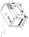
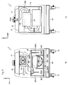
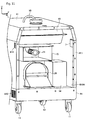
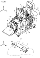
- the engine generator 1 has an engine 2, a generator 3 driven by the engine 2, and a cover 4 covering the engine 2 and the generator 3.
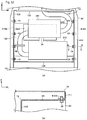
- the cover 4 has a cover body 41 which is substantially reverse U-like shaped when viewed in side and is opened at left, right and bottom sides, a pair of side lids 42 and 43 covering left and right side openings of the cover body 41, and a lower casing 44 covering a lower opening of the cover body 41.
- a cover body 41 which is substantially reverse U-like shaped when viewed in side and is opened at left, right and bottom sides, a pair of side lids 42 and 43 covering left and right side openings of the cover body 41, and a lower casing 44 covering a lower opening of the cover body 41.
- two attachment surfaces 411 are provided to which the side lids 42 and 43 are attached.
- an operation panel 5 is provided for controlling the engine generator 1.
- two plug sockets 51 having waterproof covers and the like are provided.
- a door 6 is provided at the substantially longitudinal center of the cover body 41. The door 6 can be rotated laterally with its left side as a rotation fulcrum so as to be opened and closed.
- a hook 10 is provided for pulling up the engine generator 1.
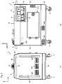
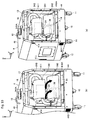
- external openings 412 and 413 are formed for sucking outside air into the cover 4.
- the external opening 412 is arranged at the upper left portion of the front side of the cover body 41, and the external opening 413 is arranged at the lower right portion of the front side of the cover body 41.
- external openings 414 and 415 are formed for sucking outside air into the cover 4.
- the external opening 414 is arranged at the upper left portion of the rear side of the cover body 41, and the external opening 415 is arranged at the lower right portion of the rear side of the cover body 41.
- the external opening 412 at the front side of the cover body 41 and the external opening 414 at the rear side of the cover body 41 are arranged symmetrically longitudinally, and the external opening 413 at the front side of the cover body 41 and the external opening 415 at the rear side of the cover body 41 are arranged symmetrically longitudinally.
- two intake ducts 7 are provided respectively inside the external openings 412 and 414 at the front and rear sides of the cover body 41. The intake ducts 7 will be explained later.
- a left handle 8 is provided which is a handle at the time of moving the engine generator 1.
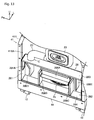
- an external opening 421 is formed for discharging air in the cover 4 to the outside.
- the external opening 421 is arranged at the substantially longitudinal center of the left side lid 42.
- two pressed ribs 422 which are respectively extended vertically are formed. Accordingly, the rigidity of the left side lid 42 is improved.
- the pressed ribs 422 are formed so as to be recessed toward the inside of the cover 4.
- a right handle 9 is provided which is a handle at the time of moving the engine generator 1.
- an external opening 431 is formed for sucking outside air into the cover 4.
- the external opening 431 is arranged at the substantially longitudinal center of the right side lid 43.
- two pressed ribs 432 which are respectively extended vertically are formed. Accordingly, the rigidity of the right side lid 43 is improved.
- the pressed ribs 432 are formed so as to be recessed toward the inside of the cover 4.
- external openings 441 and 442 are formed for sucking outside air into the cover 4.
- the external opening 441 is arranged at the left portion of the front side of the lower casing 44, and the external opening 442 is arranged at a position near the lateral center of the front side of the lower casing 44.
- an external opening 443 is formed through which outside air is sucked into the cover 4.
- the external opening 443 is arranged at the left side of the rear portion of the lower casing 44.
- the external opening 441 at the front side of the lower casing 44 and the external opening 443 at the rear side of the lower casing 44 are arranged symmetrically longitudinally.
- Two fixed casters 11 and two free casters 12 are attached to the four corners of the lower surface of the lower casing 44.
- the fixed casters 11 are arranged at the left side of the lower surface of the lower casing 44, and the free casters 12 are arranged at the right side of the lower surface of the lower casing 44. Accordingly, the engine generator 1 can be moved easily and the moving direction of the engine generator 1 can be changed easily.
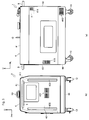
- a cylinder head 22 is attached above a cylinder block 21.
- a fan casing 26 is attached in which an engine cooling fan 25 is stored.
- the engine cooling fan 25 is rotated by power of a crankshaft (not shown).
- An intake port and an exhaust port are formed in the cylinder head 22.
- An air cleaner 23 is attached to the intake port, and an exhaust pipe 24 is attached to the exhaust port.
- the air cleaner 23 is connected to an intake box 28 via an intake hose 27.
- openings 281A and 282A are respectively formed.
- Each of the openings 281A and 282A at the front and rear sides are substantially rectangular and vertically long when viewed in front.
- the exhaust pipe 24 is provided laterally, and mufflers 241 and 242 are provided at the middle of the exhaust pipe 24.
- the mufflers 241 and 242 are housed in a muffler box 13 and aligned above and below.
- a tail pipe 243 of the exhaust pipe 24 is extended upward, and an exhaust port 243A of the tail pipe 243 is projected upward from the upper surface of the cover body 41.
- the exhaust port 243A is arranged at the substantially center of the engine generator 1 in the longitudinal direction.
- the exhaust port 243A is kept away from the side of the operation panel 5 (the front side) of the engine generator 1, whereby exhaust gas discharged from the exhaust port 243A is hardly blown to an operator at the side of the operation panel 5 (the front side) of the engine generator 1.
- the generator 3 is arranged at the left of the engine 2.
- the generator 3 has a generator body 31 constructed by a rotor (not shown) and the like, and at the left and right sides of the generator body 31, a generator rear bracket 32 and a generator cooling fan 33 are respectively provided.
- the generator cooling fan 33 is covered by a generator exhaust duct 34.
- the rotor of the generator body 31 and the generator cooling fan 33 are rotated by power of the crankshaft of the engine 2.
- a generator intake duct 36 is provided which introduces air to the side of the generator cooling fan 33.
- the air introduced by the generator intake duct 36 is sucked through the external openings 441 and 442 at the front side of the lower casing 44, the external opening 443 at the rear side of the lower casing 44 (see Fig. 3(a) ) and the like.
- a battery 14 is provided before the generator 3, a battery 14 is provided. By opening and closing the door 6 (see Fig. 1 ), the maintenance of the battery 14 and the like can be performed easily.
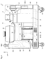
- an exhaust duct 15 is provided above the generator 3, and above the exhaust duct 15, a fuel tank 16 is provided in which fuel for the engine 2 is stored.
- the exhaust duct 15 is provided laterally, and the left and right sides thereof are opened.
- the left and right ends of the exhaust duct 15 are fixed respectively to the right side surface of the muffler box 13 and the left side surface of the engine 2 (the cylinder block 21 or the like) by bolts (not shown) or the like.
- the exhaust duct 15 is attached to an attachment base 321 attached to the upper surface of the generator rear bracket 32. Details of the attachment base 321 will be discussed later.
- the intake duct 7 has a bottom and an opening 71 is provided in the upper side thereof.
- the intake duct 7 is arranged below the upper surface of the muffler box 13 for a predetermined distance along the rear surface of the muffler box 13.
- a sponge member 17 as a sound insulator is stuck.
- a part of the sponge member 17 (sponge piece 171 shown in Fig. 6 ) is provided between the upper portion of the intake duct 7 and the rear surface of the muffler box 13 so as to cover only the left half of the opening 71, that is, so as not to cover the right half of the opening 71.
- an air passage 18 is formed by the rear surface of the muffler box 13 and the sponge member 17.
- air sucked through the external opening 414 runs in the intake duct 7 and flows into the air passage 18 through the opening 71. Then, air in the air passage 18 runs upward along the muffler box 13, and flows out from the air passage 18 through the upper end of the air passage 18 and runs near the fuel tank 16. Accordingly, the air sucked through the external opening 414 is introduced into the cover 4 by the intake duct 7. Similarly, air sucked through the external opening 412 is introduced into the cover 4 by the intake duct 7.
- the air having run near the fuel tank 16 flows into the exhaust duct 15 through the front end opening of the exhaust duct 15, and runs from the exhaust duct 15 in the muffler box 13 and is discharged outside the cover 4 through the external opening 421.
- the intake ducts 7 are arranged below as much as possible from the upper surface of the muffler box 13.
- a rib 416 is formed at the left side of the cover body 41. Similarly to the left side of the cover body 41, a rib 416 is formed at the right side of the cover body 41.
- the rib 416 is constructed by a front rib 416A formed at the front side of the cover body 41 and a rear rib 416B formed at the rear side of the cover body 41.
- the front and rear ribs 416A and 416B are bent toward the inner side of the cover body 41 substantially perpendicularly to the attachment surface 411 at the side of the free end of the attachment surface 411.
- the muffler box 13 is a box-like member constructed by combining a front plate 131, a rear plate 132, a top plate 133, a bottom plate 134 and a right side plate 135 etc., and the left side of the muffler box 13 is opened.
- the left opening of the muffler box 13 is covered by the left side lid 42.
- an insertion hole 133A is formed into which the tail pipe 243 (the exhaust port 243A) of the exhaust pipe 24 is inserted.
- an opening 135A is formed which is connected to the left end of the exhaust duct 15. As shown in Fig.
- the front plate 131 is fixed to the front rib 416A by a plurality of bolts (in this embodiment, four bolts) 19
- the rear plate 132 is fixed to the rear rib 416B by a plurality of bolts (in this embodiment, four bolts) 19.
- the intake box 28 is a box-like member constructed by combining a front plate 281, a rear plate 282, a top plate 283, a bottom plate 284 and a left side plate 285, and the right side of the intake box 28 is opened.
- the right opening of the intake box 28 is covered by the right side lid 43.
- One of the ends of the intake hose 27 is connected to the front side of the top plate 283.
- the other end of the intake hose 27 is connected to the air cleaner 23.
- the openings 281A and 282A mentioned above are formed respectively in the front plate 281 and the rear plate 282.
- the opening 281A of the front side is arranged to face the external opening 413, and the opening 282A of the rear side is arranged to face the external opening 415.
- the front plate 281 and the rear plate 282 are fixed to the front rib 416A by a plurality of bolts (in this embodiment, two bolts) 19
- the rear plate 282 is fixed to the rear rib 416B by a plurality of bolts (in this embodiment, two bolts) 19.
- an opening 285A facing the engine cooling fan 25 is formed in the left side plate 285.
- the opening 285A is substantially circular when viewed in side, and the upper half thereof is covered by a cover 286A attached to the right side lid 43.
- the cover 286A is substantially rectangular and laterally long when viewed in side.
- inner partition plates 286B and 286C are respectively provided at the front and rear sides of the cover 286A.
- An outer partition plate 286D is provided between the inner partition plate 286B of the front side and the front plate 281, and an outer partition plate 286E is provided between the partition plate 286C of the front side and the rear plate 282.
- the inside of the intake box 28 is partitioned.
- the inner partition plates 286B and 286C are provided upright on the bottom plate 284, and the outer partition plates 286D and 286E are provided to be pendent from the top plate 283. Namely, the inner partition plates 286B and 286C and the outer partition plates 286D and 286E are arranged alternately longitudinally.
- the outer partition plate 286D of the front side is arranged between the connection part of the right opening of the intake box 28 and the intake hose 27 (connection part C shown in Fig. 14 ) and the opening 281A (the external opening 413).
- the outer partition plate 286D of the front side is constructed by an inclination part 286Da facing the opening 281A aslant and a perpendicular part 286Db which is pendent from the lower end (end opposite to the connection part C) of the inclination part 286Da and faces the opening 281A frontally.
- the inclination part 286Da is inclined so that the distance to the opening 281A (distance L1 shown in Fig. 14 ) is longer at the lower side.
- Sponge members 17 are stuck respectively to the surfaces of the outer partition plate 286D of the front side and the inner partition plate 286B facing each other, the surfaces of the outer partition plate 286E of the rear side and the inner partition plate 286C facing each other, and the upper and lower end surfaces of the cover 286A.
- Sponge members (not shown) as sound insulators are also stuck to the inner surfaces of the top plate 283, the bottom plate 284 and the left side plate 285.
- air sucked from the external opening 413 at the front side of the cover body 41 flows into the intake box 28 through the opening 281A.
- Air from the opening 281A is divided into two, and one of the two passes below the outer partition plate 286D and then is sucked into the air cleaner 23 via the intake hose 27, and the other of the two runs above the inner partition plate 286B and is sucked into the engine cooling fan 25 via the opening 285A.
- the inclination part 286Da is inclined so that the distance L1 to the front opening 281A is longer at the lower side, that is, the downstream side of the air flow, whereby the area of the passage through which air flows between the outer partition plate 286D and the inner surface of the front plate 281, and the air from the opening 281A flows smoothly.
- intake sound of the air cleaner 23 passes below the outer partition plate 286D and then leaks via the opening 281A through the external opening 413.
- the air sucked into the engine cooling fan 25 flows into the exhaust duct 15 through the right end opening of the exhaust duct 15, runs from the exhaust duct 15 to the muffler box 13, and is discharged outside the cover 4 through the external opening 421.
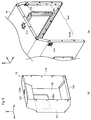
- the attachment base 321 is a metal platy member, and front and rear ends thereof are formed substantially crank-like. At the front and rear ends of the attachment base 321, bolt holes (not shown) are formed through which two bolts 321A are inserted, and the attachment base 321 is attached to the generator rear bracket 32 by the bolts 321A. Between the front and rear ends of the attachment base 321, two bolt holes 321C are formed through which two bolts 321B are inserted, and the exhaust duct 15 is fixed to the attachment base 321 by the bolts 321B.
- the engine 2 and the generator 3 are fixed on a damper stay 20.
- the exhaust duct 15 is fixed via the attachment base 321 to the generator 3 (the generator rear bracket 32) and is also fixed to the engine 2. Accordingly, the exhaust duct 15, the engine 2, the generator 3 and the damper stay 20 are constructed integrally so as to improve the rigidity thereof.
- the attachment base 321 is provided independently from the generator rear bracket 32 (bracket).
- the attachment base may alternatively be provided integrally with the bracket.
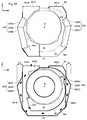
- the generator exhaust duct 34 covers the circular perimeters of the generator cooling fan 33 and a generator front bracket 35, and air runs in the generator exhaust duct 34.
- the generator cooling fan 33 rotates counterclockwise when viewed in left side (when the side of the engine 2 is seen from the side of the generator 3 in the lateral direction), and rotation direction of air in the generator exhaust duct 34 is counterclockwise.
- the generator exhaust duct 34 has a duct body 341 which is opened upward so as to be U-like shaped. At the ends of the duct body 341 at the side of upstream of the rotation and the side of downstream of the rotation, attachment parts 341A and 341B are respectively provided which are attached to the lower surface of the exhaust duct 15. At the end of the duct body 341 at the side of downstream of the rotation, an opening 341C is provided. The opening 341C is connect to an opening (not shown) formed in the lower surface of the exhaust duct 15.
- openings 341D and 341E are formed at the front and rear sides of the duct body 341.
- the opening 341D of the front side is covered by a first expansion cover 342, and the opening 341E of the rear side is covered by a second expansion cover 343.
- the first and second expansion covers 342 and 343 expand outward in the rotational radial direction of the generator cooling fan 33.
- the generator cooling fan 33 is covered by the generator front bracket 35 having first and second exhaust ports 351 and 352.
- the generator front bracket 35 is formed substantially scroll-like when viewed in side, and air runs in the generator front bracket 35 and is discharged through the first and second exhaust ports 351 and 352.
- the first exhaust port 351 is arranged above the rotation center of the generator cooling fan 33 (rotation center O shown in Fig. 18 ) at the front side of the generator front bracket 35
- the second exhaust port 352 is arranged below the rotation center O at the rear side of the generator front bracket 35. Air flows into the generator front bracket 35 through an opening (not shown) formed in the front side of the generator front bracket 35.
- the first expansion cover 342 is bent at its middle portion (bent part 342A shown in Fig. 18 ) and is provided so as to face the first exhaust port 351.
- the bent part 342A at the middle portion of the first expansion cover 342 is the most front position of the first expansion cover 342, and the distance from the front surface of the duct body 341 to the bent part 342A is referred to as L2.
- the first expansion cover 342 is constructed by an upstream slanting part 342B arranged upstream the bent part 342A and a downstream slanting part 342C arranged downstream the bent part 342A.
- the upstream slanting part 342B is extended aslant toward the bent part 342A from the upper portion of the front surface of the duct body 341, and the downstream slanting part 342C is extended aslant toward the bent part 342A from the lower portion of the front surface of the duct body 341.
- the second expansion cover 343 is bent at its middle portion (bent part 343A shown in Fig. 18 ) and is provided so as to face the second exhaust port 352.
- the bent part 343A at the middle portion of the second expansion cover 343 is the most rear position of the second expansion cover 343, and the distance from the rear surface of the duct body 341 to the bent part 343A is referred to as L3.
- the distance L3 is longer than the distance L2.
- the second expansion cover 343 is expanded outward in the rotational radial direction of the generator cooling fan 33 more than the first expansion cover 342.
- the second expansion cover 343 is constructed by an upstream slanting part 343B arranged upstream the bent part 343A and a downstream slanting part 343C arranged downstream the bent part 343A.
- the upstream slanting part 343B is extended aslant toward the bent part 343A from the lower portion of the rear surface of the duct body 341
- the downstream slanting part 343C is extended aslant toward the bent part 343A from the upper portion of the rear surface of the duct body 341.
- air discharged from the first exhaust port 351 of the generator front bracket 35 runs smoothly along the upstream slanting part 342B of the first expansion cover 342, and the discharged air is changed its direction at the bent part 342A and runs smoothly along the downstream slanting part 342C.
- Air discharged from the second exhaust port 352 of the generator front bracket 35 runs smoothly along the upstream slanting part 343B of the second expansion cover 343, and the discharged air is changed its direction at the bent part 343A and runs smoothly along the downstream slanting part 343C.
- the air discharged from the first and second exhaust ports 351 and 352 joins each other and is discharged from the opening 341C of the generator exhaust duct 34. Subsequently, the air discharged from the opening 341C flows into the exhaust duct 15 via the above-mentioned opening in the lower surface of the exhaust duct 15, runs from the exhaust duct 15 to the muffler box 13, and is discharged outside the cover 4 through the external opening 421.
- the two first and second expansion covers 342 and 343 are provided corresponding to the number of the first and second exhaust ports 351 and 352 of the generator front bracket 35 (bracket).
- one or three or more expansion parts may alternatively be provided corresponding to the number of the exhaust ports of the bracket.
- the first and second expansion covers 342 and 343 (expansion parts) are provided independently from the duct body 341.
- the expansion parts alternatively be provided integrally with the duct body.
- the engine generator 1 having the engine 2, the generator 3 driven by the engine 2, the cover 4 covering the engine 2 and the generator 3, and the muffler box 13 in which the mufflers 241 and 242 of the engine 2 is housed, includes the external openings 412 and 414 formed in the cover 4 (the cover body 41) for sucking outside air into the cover 4, and intake ducts 7 for introducing the air sucked via the external openings 412 and 414 into the inside of the cover 4.
- the opening 71 is formed in the upper side of the intake duct 7, and the intake duct 7 is arranged along the side surface of the muffler box 13 and below the upper surface of the muffler box 13 for a predetermined distance.
- the sponge member 17 is provided between the upper side of the intake duct 7 and the side surface of the muffler box 13 so as to cover a part of the opening 71.
- the air passage 18 is formed above the intake duct 7 by the side surface of the muffler box 13 and the sponge member 17.
- the attenuation length is extended by the air passage 18 so that the sound generated in the cover 4 is attenuated enough, thereby reducing the noise.
- the cover 4 has the cover body 41 in which both sides thereof are opened and the pair of the side lids 42 and 43 covering the openings of both sides of the cover body 41.
- the ribs 416 are formed in the openings of both sides of the cover body 41.
- the muffler box 13 is fixed to the left rib 416 among the ribs 416.
- the ribs 416 improves the rigidity of the cover body 41, and the cover body 41 and the muffler box 13 are constructed integrally so as to improve the rigidity thereof, thereby reducing the vibration of the cover body 41 so as to reduce the noise.
- the engine cooling fan 25 is provided to the engine 2.
- the external openings 413 and 415 are provided which are formed in the cover 4 (the cover body 41) for sucking outside air into the cover 4.
- the intake box 28 is provided for introducing the air sucked via the external openings 413 and 415 into the engine cooling fan 25.
- the air cleaner 23 of the engine 2 is communicated through an intake hose 27 to the intake box 28.
- the intake box 28 serves as an intake chamber, whereby it is not necessary to provide any intake chamber of exclusive use. Accordingly, by employing surplus space around the intake box 28 so as to increase the capacity of the intake box 28, the intake sound which causes the noise can be reduced. By omitting the intake chamber of exclusive use, the weight of the whole engine generator 1 can be reduced and the number of parts thereof can be reduced, whereby the cost can be reduced.
- the intake box 28 is fixed to the left rib 416 among the ribs 416.
- the cover body 41 and the intake box 28 are constructed integrally so as to improve the rigidity thereof, thereby reducing the vibration of the cover body 41 so as to reduce the noise.
- the inside of the intake box 28 is partitioned by the outer partition plate 286D, and the partition plate 286D is arranged between the connection part C of the intake box 28 and the intake hose 27 and the external opening 413.
- the attenuation length is extended by the outer partition plate 286D so that the intake sound is attenuated enough, thereby reducing the noise.
- the exhaust duct 15 for discharging air in the cover 4 to the outside is provided above the generator 3.
- the attachment base 321 to which the exhaust duct 15 is attached is provided on the upper surface of the generator 3 (the generator rear bracket 32).
- the exhaust duct 15 is attached to the attachment base 321 on the generator 3 (the generator rear bracket 32). Accordingly, the exhaust duct 15, the generator 3 and the engine 2 are constructed integrally so as to improve the rigidity thereof, thereby reducing the vibration of the exhaust duct 15 so as to reduce the noise.
- the generator cooling fan 33 is provided to the generator 3.
- the generator cooling fan 33 is covered by the generator front bracket 35 having the first and second exhaust ports 351 and 352.
- the generator front bracket 35 is covered by the generator exhaust duct 34.
- the generator exhaust duct 34 is provided therein with the first and second expansion covers 342 and 343 which expands outward along the rotational radial direction of the generator cooling fan 33 and faces the first and second exhaust ports 351 and 352.
- the first and second expansion covers 342 and 343 make the flowing of air in the vicinity of the first and second exhaust ports 351 and 352 smooth, thereby making the whole inside of the generator exhaust duct 34 smooth so as to cool efficiently the generator 3, in its turn the whole engine generator 1.
- the present invention can be employed for an engine generator.
Landscapes
- Engineering & Computer Science (AREA)
- Chemical & Material Sciences (AREA)
- Combustion & Propulsion (AREA)
- Mechanical Engineering (AREA)
- General Engineering & Computer Science (AREA)
- Physics & Mathematics (AREA)
- Acoustics & Sound (AREA)
- Motor Or Generator Cooling System (AREA)
- Motor Or Generator Frames (AREA)
Applications Claiming Priority (1)
| Application Number | Priority Date | Filing Date | Title |
|---|---|---|---|
| PCT/CN2011/000143 WO2012100376A1 (zh) | 2011-01-28 | 2011-01-28 | 引擎发电机 |
Publications (3)
| Publication Number | Publication Date |
|---|---|
| EP2669486A1 EP2669486A1 (en) | 2013-12-04 |
| EP2669486A4 EP2669486A4 (en) | 2015-02-25 |
| EP2669486B1 true EP2669486B1 (en) | 2016-07-20 |
Family
ID=46580173
Family Applications (1)
| Application Number | Title | Priority Date | Filing Date |
|---|---|---|---|
| EP11856817.9A Not-in-force EP2669486B1 (en) | 2011-01-28 | 2011-01-28 | Engine generator |
Country Status (7)
| Country | Link |
|---|---|
| US (1) | US9429068B2 (enExample) |
| EP (1) | EP2669486B1 (enExample) |
| JP (1) | JP5612213B2 (enExample) |
| CN (1) | CN103180575B (enExample) |
| AU (1) | AU2011357560B2 (enExample) |
| ES (1) | ES2598629T3 (enExample) |
| WO (1) | WO2012100376A1 (enExample) |
Families Citing this family (24)
| Publication number | Priority date | Publication date | Assignee | Title |
|---|---|---|---|---|
| CN102383926B (zh) * | 2011-10-23 | 2013-02-06 | 浙江乐恒动力科技有限公司 | 一种发动机驱动的箱式发电机 |
| US9228760B2 (en) | 2012-04-27 | 2016-01-05 | Mac, Inc. | Flameless heating system |
| EP3050196B1 (en) | 2013-09-27 | 2023-01-04 | Cummins Inc. | Electrical power generation system with multiple path cooling |
| EP3053810B1 (en) | 2013-09-30 | 2018-02-21 | Yanmar Co., Ltd. | Work vehicle |
| WO2016043297A1 (ja) * | 2014-09-19 | 2016-03-24 | ヤンマー株式会社 | エンジン発電機 |
| JP6223939B2 (ja) * | 2014-09-19 | 2017-11-01 | ヤンマー株式会社 | 舶用エンジン発電機 |
| JP6383969B2 (ja) * | 2015-03-03 | 2018-09-05 | ヤンマー株式会社 | エンジン発電機 |
| USD763191S1 (en) | 2014-09-26 | 2016-08-09 | Cummins Inc. | Genset enclosure |
| USD773395S1 (en) * | 2014-09-26 | 2016-12-06 | Cummins Inc. | Genset enclosure |
| US9764837B2 (en) * | 2014-11-14 | 2017-09-19 | Top Flight Technologies, Inc. | Micro hybrid generator system drone |
| JP6816049B2 (ja) * | 2018-02-23 | 2021-01-20 | デンヨー株式会社 | エンジン駆動作業機 |
| CN108412608A (zh) * | 2018-03-16 | 2018-08-17 | 宁德本田动力有限公司 | 一种低噪音风冷柴油变频发电机组 |
| US10927732B2 (en) * | 2018-03-28 | 2021-02-23 | Cummins Power Generation Ip, Inc. | Low noise enclosure |
| US11300034B2 (en) * | 2018-05-17 | 2022-04-12 | Champion Power Equipment, Inc. | Standby generator air flow management system |
| JP7082547B2 (ja) * | 2018-08-20 | 2022-06-08 | 日本車輌製造株式会社 | エンジン作業機 |
| CN114790938A (zh) * | 2021-01-26 | 2022-07-26 | 丁士才 | 一种节能型风冷柴油数码发电机组 |
| CN113236419B (zh) * | 2021-07-01 | 2025-04-29 | 重庆宗申通用动力机械有限公司 | 一种发电机 |
| USD1085010S1 (en) | 2023-10-11 | 2025-07-22 | Northern Tool & Equipment Company, Inc. | Generator assembly |
| USD1085006S1 (en) | 2023-10-11 | 2025-07-22 | Northern Tool & Equipment Company, Inc. | Generator assembly |
| USD1085008S1 (en) | 2023-10-11 | 2025-07-22 | Northern Tool & Equipment Company, Inc. | Generator assembly |
| USD1085007S1 (en) | 2023-10-11 | 2025-07-22 | Northern Tool & Equipment Company, Inc. | Generator assembly |
| USD1085012S1 (en) | 2023-10-11 | 2025-07-22 | Northern Tool & Equipment Company, Inc. | Generator assembly |
| USD1085011S1 (en) | 2023-10-11 | 2025-07-22 | Northern Tool & Equipment Company, Inc. | Generator assembly |
| USD1085009S1 (en) | 2023-10-11 | 2025-07-22 | Northern Tool & Equipment Company, Inc. | Generator assembly |
Family Cites Families (21)
| Publication number | Priority date | Publication date | Assignee | Title |
|---|---|---|---|---|
| DE2704697C3 (de) | 1976-02-25 | 1986-08-21 | Kabushiki Kaisha Komatsu Seisakusho, Tokio/Tokyo | Stromaggregat |
| JP3038507B2 (ja) * | 1991-04-05 | 2000-05-08 | ヤンマーディーゼル株式会社 | エンジンの防音ケース |
| JP3957366B2 (ja) * | 1997-07-03 | 2007-08-15 | 北越工業株式会社 | エンジン駆動型作業機の収納構造 |
| JPH1137509A (ja) * | 1997-07-22 | 1999-02-12 | Zexel Corp | 空調用室外機 |
| JP3800372B2 (ja) * | 1997-07-24 | 2006-07-26 | 本田技研工業株式会社 | エンジン発電機 |
| JP4054767B2 (ja) * | 2001-07-10 | 2008-03-05 | ヤンマー株式会社 | 防音型発電装置 |
| JP3778429B2 (ja) * | 2001-07-10 | 2006-05-24 | ヤンマー株式会社 | 防音型発電装置 |
| JP3934897B2 (ja) | 2001-09-25 | 2007-06-20 | 本田技研工業株式会社 | エンジン発電機 |
| DE60226682D1 (de) | 2001-10-11 | 2008-07-03 | Fuji Heavy Ind Ltd | Motorgenerator |
| JP3977046B2 (ja) | 2001-10-11 | 2007-09-19 | 富士重工業株式会社 | エンジン発電機 |
| JP2003214176A (ja) | 2002-01-25 | 2003-07-30 | Asahi Denki Kk | 防音形エンジン発電装置 |
| JP4767791B2 (ja) * | 2006-08-25 | 2011-09-07 | 本田技研工業株式会社 | エンジン駆動式作業機 |
| US7482706B2 (en) * | 2006-08-25 | 2009-01-27 | Honda Motor Co., Ltd. | Engine-driven work machine system |
| JP4897399B2 (ja) * | 2006-08-28 | 2012-03-14 | 本田技研工業株式会社 | エンジン駆動式作業機 |
| JP4804538B2 (ja) * | 2006-09-14 | 2011-11-02 | 三菱重工業株式会社 | 防音型エンジン発電機 |
| JP2008082204A (ja) * | 2006-09-26 | 2008-04-10 | Yanmar Co Ltd | エンジン発電装置 |
| CN201034044Y (zh) | 2007-05-28 | 2008-03-12 | 汕头市盈动电气有限公司 | 柴油发电机的消声装置 |
| JP2009121244A (ja) | 2007-11-12 | 2009-06-04 | Honda Motor Co Ltd | 防音密閉型発電機 |
| JP2010022998A (ja) | 2008-07-24 | 2010-02-04 | Mitsubishi Electric Corp | 空気清浄装置 |
| CN201297203Y (zh) * | 2008-09-28 | 2009-08-26 | 无锡开普动力有限公司 | 风冷发电机组 |
| JP2010222998A (ja) | 2009-03-19 | 2010-10-07 | Yanmar Co Ltd | エンジン発電機 |
-
2011
- 2011-01-28 JP JP2013528495A patent/JP5612213B2/ja active Active
- 2011-01-28 ES ES11856817.9T patent/ES2598629T3/es active Active
- 2011-01-28 WO PCT/CN2011/000143 patent/WO2012100376A1/zh not_active Ceased
- 2011-01-28 AU AU2011357560A patent/AU2011357560B2/en not_active Ceased
- 2011-01-28 EP EP11856817.9A patent/EP2669486B1/en not_active Not-in-force
- 2011-01-28 CN CN201180045976.5A patent/CN103180575B/zh not_active Expired - Fee Related
- 2011-01-28 US US13/982,025 patent/US9429068B2/en not_active Expired - Fee Related
Also Published As
| Publication number | Publication date |
|---|---|
| JP5612213B2 (ja) | 2014-10-22 |
| US9429068B2 (en) | 2016-08-30 |
| US20140209045A1 (en) | 2014-07-31 |
| EP2669486A1 (en) | 2013-12-04 |
| EP2669486A4 (en) | 2015-02-25 |
| ES2598629T3 (es) | 2017-01-30 |
| AU2011357560B2 (en) | 2015-11-26 |
| WO2012100376A1 (zh) | 2012-08-02 |
| CN103180575A (zh) | 2013-06-26 |
| JP2013537275A (ja) | 2013-09-30 |
| AU2011357560A1 (en) | 2013-08-29 |
| CN103180575B (zh) | 2015-11-25 |
Similar Documents
| Publication | Publication Date | Title |
|---|---|---|
| EP2669486B1 (en) | Engine generator | |
| JP3569890B2 (ja) | 防音型エンジン駆動作業機 | |
| JP2001348909A (ja) | 建設機械 | |
| JP2003097283A (ja) | エンジン発電機 | |
| JP5631360B2 (ja) | エンジン駆動作業機の吸気・排気構造 | |
| JPH11294160A (ja) | エンジン駆動作業機 | |
| JP6247718B2 (ja) | 低騒音型発電装置 | |
| JP3375563B2 (ja) | 防音型エンジン発電機 | |
| KR20120085618A (ko) | 건설중장비의 엔진룸 냉각장치 | |
| JP3461039B2 (ja) | 防音型エンジン作業機 | |
| JP2003254080A (ja) | 可搬形発電機 | |
| JP3957366B2 (ja) | エンジン駆動型作業機の収納構造 | |
| JP3712664B2 (ja) | 防音型発電装置 | |
| JP2014126036A (ja) | パッケージ収納型エンジン発電機 | |
| JP3974515B2 (ja) | エンジン作業機 | |
| JPH0622530U (ja) | 防音形水冷式エンジン発電機の排風処理構造 | |
| JP2008025421A (ja) | エンジン発電機 | |
| JP3974514B2 (ja) | エンジン作業機 | |
| JP2539769B2 (ja) | 防音型エンジン作業機 | |
| JP2003193861A (ja) | 防音型発電装置 | |
| JP2005145114A (ja) | 建設機械のエンジンフード、建設機械のエンジンルーム構造及び建設機械の冷却装置 | |
| JP2001280585A (ja) | 発電装置 | |
| JP4091797B2 (ja) | 防音型エンジン発電機 | |
| JP2009275662A (ja) | 作業機械のマフラ冷却構造 | |
| WO2006033223A1 (ja) | 建設機械の騒音低減構造 |
Legal Events
| Date | Code | Title | Description |
|---|---|---|---|
| PUAI | Public reference made under article 153(3) epc to a published international application that has entered the european phase |
Free format text: ORIGINAL CODE: 0009012 |
|
| 17P | Request for examination filed |
Effective date: 20130828 |
|
| AK | Designated contracting states |
Kind code of ref document: A1 Designated state(s): AL AT BE BG CH CY CZ DE DK EE ES FI FR GB GR HR HU IE IS IT LI LT LU LV MC MK MT NL NO PL PT RO RS SE SI SK SM TR |
|
| DAX | Request for extension of the european patent (deleted) | ||
| A4 | Supplementary search report drawn up and despatched |
Effective date: 20150123 |
|
| RIC1 | Information provided on ipc code assigned before grant |
Ipc: F02B 63/04 20060101AFI20150119BHEP Ipc: F02B 77/13 20060101ALI20150119BHEP |
|
| GRAP | Despatch of communication of intention to grant a patent |
Free format text: ORIGINAL CODE: EPIDOSNIGR1 |
|
| RIC1 | Information provided on ipc code assigned before grant |
Ipc: F02B 77/13 20060101ALI20160126BHEP Ipc: F02B 63/04 20060101AFI20160126BHEP |
|
| INTG | Intention to grant announced |
Effective date: 20160217 |
|
| GRAS | Grant fee paid |
Free format text: ORIGINAL CODE: EPIDOSNIGR3 |
|
| GRAA | (expected) grant |
Free format text: ORIGINAL CODE: 0009210 |
|
| RAP1 | Party data changed (applicant data changed or rights of an application transferred) |
Owner name: HIMOINSA CHINA CO., LTD Owner name: YANMAR CO., LTD. |
|
| RIN1 | Information on inventor provided before grant (corrected) |
Inventor name: HIBI, SHINJI Inventor name: LI, SANPING |
|
| AK | Designated contracting states |
Kind code of ref document: B1 Designated state(s): AL AT BE BG CH CY CZ DE DK EE ES FI FR GB GR HR HU IE IS IT LI LT LU LV MC MK MT NL NO PL PT RO RS SE SI SK SM TR |
|
| REG | Reference to a national code |
Ref country code: GB Ref legal event code: FG4D |
|
| RIN1 | Information on inventor provided before grant (corrected) |
Inventor name: HIBI, SHINJI Inventor name: LI, SANPING |
|
| REG | Reference to a national code |
Ref country code: CH Ref legal event code: EP |
|
| REG | Reference to a national code |
Ref country code: IE Ref legal event code: FG4D |
|
| REG | Reference to a national code |
Ref country code: AT Ref legal event code: REF Ref document number: 814297 Country of ref document: AT Kind code of ref document: T Effective date: 20160815 |
|
| REG | Reference to a national code |
Ref country code: DE Ref legal event code: R096 Ref document number: 602011028467 Country of ref document: DE |
|
| REG | Reference to a national code |
Ref country code: LT Ref legal event code: MG4D |
|
| REG | Reference to a national code |
Ref country code: NL Ref legal event code: MP Effective date: 20160720 |
|
| RIN2 | Information on inventor provided after grant (corrected) |
Inventor name: HIBI, SHINJI Inventor name: LI, SANPING |
|
| RAP2 | Party data changed (patent owner data changed or rights of a patent transferred) |
Owner name: YANMAR CO., LTD. Owner name: HIMOINSA CHINA CO., LTD |
|
| RIN2 | Information on inventor provided after grant (corrected) |
Inventor name: HIBI, SHINJI Inventor name: LI, SANPING |
|
| REG | Reference to a national code |
Ref country code: AT Ref legal event code: MK05 Ref document number: 814297 Country of ref document: AT Kind code of ref document: T Effective date: 20160720 |
|
| REG | Reference to a national code |
Ref country code: FR Ref legal event code: PLFP Year of fee payment: 7 |
|
| REG | Reference to a national code |
Ref country code: ES Ref legal event code: FG2A Ref document number: 2598629 Country of ref document: ES Kind code of ref document: T3 Effective date: 20170130 |
|
| PG25 | Lapsed in a contracting state [announced via postgrant information from national office to epo] |
Ref country code: NL Free format text: LAPSE BECAUSE OF FAILURE TO SUBMIT A TRANSLATION OF THE DESCRIPTION OR TO PAY THE FEE WITHIN THE PRESCRIBED TIME-LIMIT Effective date: 20160720 Ref country code: LT Free format text: LAPSE BECAUSE OF FAILURE TO SUBMIT A TRANSLATION OF THE DESCRIPTION OR TO PAY THE FEE WITHIN THE PRESCRIBED TIME-LIMIT Effective date: 20160720 Ref country code: IT Free format text: LAPSE BECAUSE OF FAILURE TO SUBMIT A TRANSLATION OF THE DESCRIPTION OR TO PAY THE FEE WITHIN THE PRESCRIBED TIME-LIMIT Effective date: 20160720 Ref country code: NO Free format text: LAPSE BECAUSE OF FAILURE TO SUBMIT A TRANSLATION OF THE DESCRIPTION OR TO PAY THE FEE WITHIN THE PRESCRIBED TIME-LIMIT Effective date: 20161020 Ref country code: RS Free format text: LAPSE BECAUSE OF FAILURE TO SUBMIT A TRANSLATION OF THE DESCRIPTION OR TO PAY THE FEE WITHIN THE PRESCRIBED TIME-LIMIT Effective date: 20160720 Ref country code: FI Free format text: LAPSE BECAUSE OF FAILURE TO SUBMIT A TRANSLATION OF THE DESCRIPTION OR TO PAY THE FEE WITHIN THE PRESCRIBED TIME-LIMIT Effective date: 20160720 Ref country code: IS Free format text: LAPSE BECAUSE OF FAILURE TO SUBMIT A TRANSLATION OF THE DESCRIPTION OR TO PAY THE FEE WITHIN THE PRESCRIBED TIME-LIMIT Effective date: 20161120 Ref country code: HR Free format text: LAPSE BECAUSE OF FAILURE TO SUBMIT A TRANSLATION OF THE DESCRIPTION OR TO PAY THE FEE WITHIN THE PRESCRIBED TIME-LIMIT Effective date: 20160720 |
|
| PG25 | Lapsed in a contracting state [announced via postgrant information from national office to epo] |
Ref country code: BE Free format text: LAPSE BECAUSE OF FAILURE TO SUBMIT A TRANSLATION OF THE DESCRIPTION OR TO PAY THE FEE WITHIN THE PRESCRIBED TIME-LIMIT Effective date: 20160720 Ref country code: SE Free format text: LAPSE BECAUSE OF FAILURE TO SUBMIT A TRANSLATION OF THE DESCRIPTION OR TO PAY THE FEE WITHIN THE PRESCRIBED TIME-LIMIT Effective date: 20160720 Ref country code: AT Free format text: LAPSE BECAUSE OF FAILURE TO SUBMIT A TRANSLATION OF THE DESCRIPTION OR TO PAY THE FEE WITHIN THE PRESCRIBED TIME-LIMIT Effective date: 20160720 Ref country code: PL Free format text: LAPSE BECAUSE OF FAILURE TO SUBMIT A TRANSLATION OF THE DESCRIPTION OR TO PAY THE FEE WITHIN THE PRESCRIBED TIME-LIMIT Effective date: 20160720 Ref country code: GR Free format text: LAPSE BECAUSE OF FAILURE TO SUBMIT A TRANSLATION OF THE DESCRIPTION OR TO PAY THE FEE WITHIN THE PRESCRIBED TIME-LIMIT Effective date: 20161021 Ref country code: LV Free format text: LAPSE BECAUSE OF FAILURE TO SUBMIT A TRANSLATION OF THE DESCRIPTION OR TO PAY THE FEE WITHIN THE PRESCRIBED TIME-LIMIT Effective date: 20160720 Ref country code: PT Free format text: LAPSE BECAUSE OF FAILURE TO SUBMIT A TRANSLATION OF THE DESCRIPTION OR TO PAY THE FEE WITHIN THE PRESCRIBED TIME-LIMIT Effective date: 20161121 |
|
| REG | Reference to a national code |
Ref country code: DE Ref legal event code: R097 Ref document number: 602011028467 Country of ref document: DE |
|
| PG25 | Lapsed in a contracting state [announced via postgrant information from national office to epo] |
Ref country code: EE Free format text: LAPSE BECAUSE OF FAILURE TO SUBMIT A TRANSLATION OF THE DESCRIPTION OR TO PAY THE FEE WITHIN THE PRESCRIBED TIME-LIMIT Effective date: 20160720 Ref country code: RO Free format text: LAPSE BECAUSE OF FAILURE TO SUBMIT A TRANSLATION OF THE DESCRIPTION OR TO PAY THE FEE WITHIN THE PRESCRIBED TIME-LIMIT Effective date: 20160720 |
|
| PLBE | No opposition filed within time limit |
Free format text: ORIGINAL CODE: 0009261 |
|
| STAA | Information on the status of an ep patent application or granted ep patent |
Free format text: STATUS: NO OPPOSITION FILED WITHIN TIME LIMIT |
|
| PG25 | Lapsed in a contracting state [announced via postgrant information from national office to epo] |
Ref country code: CZ Free format text: LAPSE BECAUSE OF FAILURE TO SUBMIT A TRANSLATION OF THE DESCRIPTION OR TO PAY THE FEE WITHIN THE PRESCRIBED TIME-LIMIT Effective date: 20160720 Ref country code: SM Free format text: LAPSE BECAUSE OF FAILURE TO SUBMIT A TRANSLATION OF THE DESCRIPTION OR TO PAY THE FEE WITHIN THE PRESCRIBED TIME-LIMIT Effective date: 20160720 Ref country code: SK Free format text: LAPSE BECAUSE OF FAILURE TO SUBMIT A TRANSLATION OF THE DESCRIPTION OR TO PAY THE FEE WITHIN THE PRESCRIBED TIME-LIMIT Effective date: 20160720 Ref country code: BG Free format text: LAPSE BECAUSE OF FAILURE TO SUBMIT A TRANSLATION OF THE DESCRIPTION OR TO PAY THE FEE WITHIN THE PRESCRIBED TIME-LIMIT Effective date: 20161020 Ref country code: DK Free format text: LAPSE BECAUSE OF FAILURE TO SUBMIT A TRANSLATION OF THE DESCRIPTION OR TO PAY THE FEE WITHIN THE PRESCRIBED TIME-LIMIT Effective date: 20160720 |
|
| 26N | No opposition filed |
Effective date: 20170421 |
|
| PG25 | Lapsed in a contracting state [announced via postgrant information from national office to epo] |
Ref country code: SI Free format text: LAPSE BECAUSE OF FAILURE TO SUBMIT A TRANSLATION OF THE DESCRIPTION OR TO PAY THE FEE WITHIN THE PRESCRIBED TIME-LIMIT Effective date: 20160720 |
|
| REG | Reference to a national code |
Ref country code: CH Ref legal event code: PL |
|
| GBPC | Gb: european patent ceased through non-payment of renewal fee |
Effective date: 20170128 |
|
| PG25 | Lapsed in a contracting state [announced via postgrant information from national office to epo] |
Ref country code: MC Free format text: LAPSE BECAUSE OF FAILURE TO SUBMIT A TRANSLATION OF THE DESCRIPTION OR TO PAY THE FEE WITHIN THE PRESCRIBED TIME-LIMIT Effective date: 20160720 |
|
| PG25 | Lapsed in a contracting state [announced via postgrant information from national office to epo] |
Ref country code: CH Free format text: LAPSE BECAUSE OF NON-PAYMENT OF DUE FEES Effective date: 20170131 Ref country code: LI Free format text: LAPSE BECAUSE OF NON-PAYMENT OF DUE FEES Effective date: 20170131 |
|
| REG | Reference to a national code |
Ref country code: IE Ref legal event code: MM4A |
|
| PG25 | Lapsed in a contracting state [announced via postgrant information from national office to epo] |
Ref country code: GB Free format text: LAPSE BECAUSE OF NON-PAYMENT OF DUE FEES Effective date: 20170128 Ref country code: LU Free format text: LAPSE BECAUSE OF NON-PAYMENT OF DUE FEES Effective date: 20170128 |
|
| REG | Reference to a national code |
Ref country code: FR Ref legal event code: PLFP Year of fee payment: 8 |
|
| PG25 | Lapsed in a contracting state [announced via postgrant information from national office to epo] |
Ref country code: IE Free format text: LAPSE BECAUSE OF NON-PAYMENT OF DUE FEES Effective date: 20170128 |
|
| PG25 | Lapsed in a contracting state [announced via postgrant information from national office to epo] |
Ref country code: MT Free format text: LAPSE BECAUSE OF NON-PAYMENT OF DUE FEES Effective date: 20170128 |
|
| PG25 | Lapsed in a contracting state [announced via postgrant information from national office to epo] |
Ref country code: AL Free format text: LAPSE BECAUSE OF FAILURE TO SUBMIT A TRANSLATION OF THE DESCRIPTION OR TO PAY THE FEE WITHIN THE PRESCRIBED TIME-LIMIT Effective date: 20160720 |
|
| PG25 | Lapsed in a contracting state [announced via postgrant information from national office to epo] |
Ref country code: HU Free format text: LAPSE BECAUSE OF FAILURE TO SUBMIT A TRANSLATION OF THE DESCRIPTION OR TO PAY THE FEE WITHIN THE PRESCRIBED TIME-LIMIT; INVALID AB INITIO Effective date: 20110128 |
|
| PG25 | Lapsed in a contracting state [announced via postgrant information from national office to epo] |
Ref country code: CY Free format text: LAPSE BECAUSE OF NON-PAYMENT OF DUE FEES Effective date: 20160720 |
|
| PG25 | Lapsed in a contracting state [announced via postgrant information from national office to epo] |
Ref country code: MK Free format text: LAPSE BECAUSE OF FAILURE TO SUBMIT A TRANSLATION OF THE DESCRIPTION OR TO PAY THE FEE WITHIN THE PRESCRIBED TIME-LIMIT Effective date: 20160720 |
|
| PGFP | Annual fee paid to national office [announced via postgrant information from national office to epo] |
Ref country code: FR Payment date: 20191216 Year of fee payment: 10 |
|
| PG25 | Lapsed in a contracting state [announced via postgrant information from national office to epo] |
Ref country code: TR Free format text: LAPSE BECAUSE OF FAILURE TO SUBMIT A TRANSLATION OF THE DESCRIPTION OR TO PAY THE FEE WITHIN THE PRESCRIBED TIME-LIMIT Effective date: 20160720 |
|
| PGFP | Annual fee paid to national office [announced via postgrant information from national office to epo] |
Ref country code: DE Payment date: 20200114 Year of fee payment: 10 |
|
| REG | Reference to a national code |
Ref country code: DE Ref legal event code: R082 Ref document number: 602011028467 Country of ref document: DE Representative=s name: JOSTARNDT PATENTANWALTS-AG, DE Ref country code: DE Ref legal event code: R081 Ref document number: 602011028467 Country of ref document: DE Owner name: YANMAR POWER TECHNOLOGY CO., LTD., JP Free format text: FORMER OWNERS: HIMOINSA CHINA CO., LTD, CHANGZHOU, JIANGSU, CN; YANMAR CO., LTD., OSAKA-SHI, JP Ref country code: DE Ref legal event code: R081 Ref document number: 602011028467 Country of ref document: DE Owner name: HIMOINSA CHINA CO., LTD, CHANGZHOU, CN Free format text: FORMER OWNERS: HIMOINSA CHINA CO., LTD, CHANGZHOU, JIANGSU, CN; YANMAR CO., LTD., OSAKA-SHI, JP |
|
| REG | Reference to a national code |
Ref country code: ES Ref legal event code: PC2A Owner name: YANMAR POWER TECHNOLOGY CO., LTD. Effective date: 20201029 |
|
| REG | Reference to a national code |
Ref country code: DE Ref legal event code: R119 Ref document number: 602011028467 Country of ref document: DE |
|
| PG25 | Lapsed in a contracting state [announced via postgrant information from national office to epo] |
Ref country code: FR Free format text: LAPSE BECAUSE OF NON-PAYMENT OF DUE FEES Effective date: 20210131 |
|
| PG25 | Lapsed in a contracting state [announced via postgrant information from national office to epo] |
Ref country code: DE Free format text: LAPSE BECAUSE OF NON-PAYMENT OF DUE FEES Effective date: 20210803 |
|
| PGFP | Annual fee paid to national office [announced via postgrant information from national office to epo] |
Ref country code: ES Payment date: 20220325 Year of fee payment: 12 |
|
| REG | Reference to a national code |
Ref country code: ES Ref legal event code: FD2A Effective date: 20240403 |
|
| PG25 | Lapsed in a contracting state [announced via postgrant information from national office to epo] |
Ref country code: ES Free format text: LAPSE BECAUSE OF NON-PAYMENT OF DUE FEES Effective date: 20230129 |
|
| PG25 | Lapsed in a contracting state [announced via postgrant information from national office to epo] |
Ref country code: ES Free format text: LAPSE BECAUSE OF NON-PAYMENT OF DUE FEES Effective date: 20230129 |