EP2617093B1 - Ionic gel electrolyte, energy storage devices, and methods of manufacture thereof - Google Patents
Ionic gel electrolyte, energy storage devices, and methods of manufacture thereof Download PDFInfo
- Publication number
- EP2617093B1 EP2617093B1 EP11825825.0A EP11825825A EP2617093B1 EP 2617093 B1 EP2617093 B1 EP 2617093B1 EP 11825825 A EP11825825 A EP 11825825A EP 2617093 B1 EP2617093 B1 EP 2617093B1
- Authority
- EP
- European Patent Office
- Prior art keywords
- electrolyte
- ionic liquid
- zinc
- recited
- printed
- Prior art date
- Legal status (The legal status is an assumption and is not a legal conclusion. Google has not performed a legal analysis and makes no representation as to the accuracy of the status listed.)
- Active
Links
- 239000011245 gel electrolyte Substances 0.000 title description 67
- 238000000034 method Methods 0.000 title description 56
- 238000004146 energy storage Methods 0.000 title description 23
- 238000004519 manufacturing process Methods 0.000 title description 13
- 239000003792 electrolyte Substances 0.000 claims description 122
- 239000002608 ionic liquid Substances 0.000 claims description 113
- 239000011701 zinc Substances 0.000 claims description 52
- HCHKCACWOHOZIP-UHFFFAOYSA-N Zinc Chemical compound [Zn] HCHKCACWOHOZIP-UHFFFAOYSA-N 0.000 claims description 47
- 229920000642 polymer Polymers 0.000 claims description 44
- 229910052725 zinc Inorganic materials 0.000 claims description 44
- NUJOXMJBOLGQSY-UHFFFAOYSA-N manganese dioxide Chemical compound O=[Mn]=O NUJOXMJBOLGQSY-UHFFFAOYSA-N 0.000 claims description 43
- 150000003839 salts Chemical class 0.000 claims description 35
- -1 zinc cations Chemical class 0.000 claims description 31
- 150000003751 zinc Chemical class 0.000 claims description 27
- 150000002500 ions Chemical class 0.000 claims description 26
- 239000000203 mixture Substances 0.000 claims description 20
- GNTDGMZSJNCJKK-UHFFFAOYSA-N divanadium pentaoxide Chemical compound O=[V](=O)O[V](=O)=O GNTDGMZSJNCJKK-UHFFFAOYSA-N 0.000 claims description 12
- 150000001768 cations Chemical class 0.000 claims description 10
- 150000001450 anions Chemical class 0.000 claims description 9
- 229910044991 metal oxide Inorganic materials 0.000 claims description 8
- 238000000926 separation method Methods 0.000 claims description 8
- 238000004891 communication Methods 0.000 claims description 7
- 150000004706 metal oxides Chemical class 0.000 claims description 7
- 229920002981 polyvinylidene fluoride Polymers 0.000 claims description 7
- 230000005540 biological transmission Effects 0.000 claims description 5
- 238000007254 oxidation reaction Methods 0.000 claims description 5
- ZXMGHDIOOHOAAE-UHFFFAOYSA-N 1,1,1-trifluoro-n-(trifluoromethylsulfonyl)methanesulfonamide Chemical compound FC(F)(F)S(=O)(=O)NS(=O)(=O)C(F)(F)F ZXMGHDIOOHOAAE-UHFFFAOYSA-N 0.000 claims description 4
- RAXXELZNTBOGNW-UHFFFAOYSA-O Imidazolium Chemical compound C1=C[NH+]=CN1 RAXXELZNTBOGNW-UHFFFAOYSA-O 0.000 claims description 3
- RWRDLPDLKQPQOW-UHFFFAOYSA-O Pyrrolidinium ion Chemical compound C1CC[NH2+]C1 RWRDLPDLKQPQOW-UHFFFAOYSA-O 0.000 claims description 3
- DTQVDTLACAAQTR-UHFFFAOYSA-M Trifluoroacetate Chemical compound [O-]C(=O)C(F)(F)F DTQVDTLACAAQTR-UHFFFAOYSA-M 0.000 claims description 3
- 229910000428 cobalt oxide Inorganic materials 0.000 claims description 3
- KTQDYGVEEFGIIL-UHFFFAOYSA-N n-fluorosulfonylsulfamoyl fluoride Chemical compound FS(=O)(=O)NS(F)(=O)=O KTQDYGVEEFGIIL-UHFFFAOYSA-N 0.000 claims description 3
- 229920001296 polysiloxane Polymers 0.000 claims description 3
- 239000011829 room temperature ionic liquid solvent Substances 0.000 claims description 3
- ITMCEJHCFYSIIV-UHFFFAOYSA-N triflic acid Chemical compound OS(=O)(=O)C(F)(F)F ITMCEJHCFYSIIV-UHFFFAOYSA-N 0.000 claims description 3
- BQCIDUSAKPWEOX-UHFFFAOYSA-N 1,1-Difluoroethene Chemical compound FC(F)=C BQCIDUSAKPWEOX-UHFFFAOYSA-N 0.000 claims description 2
- QGZKDVFQNNGYKY-UHFFFAOYSA-O Ammonium Chemical compound [NH4+] QGZKDVFQNNGYKY-UHFFFAOYSA-O 0.000 claims description 2
- NQRYJNQNLNOLGT-UHFFFAOYSA-O Piperidinium(1+) Chemical compound C1CC[NH2+]CC1 NQRYJNQNLNOLGT-UHFFFAOYSA-O 0.000 claims description 2
- GWEVSGVZZGPLCZ-UHFFFAOYSA-N Titan oxide Chemical compound O=[Ti]=O GWEVSGVZZGPLCZ-UHFFFAOYSA-N 0.000 claims description 2
- IVMYJDGYRUAWML-UHFFFAOYSA-N cobalt(ii) oxide Chemical compound [Co]=O IVMYJDGYRUAWML-UHFFFAOYSA-N 0.000 claims description 2
- 229910000464 lead oxide Inorganic materials 0.000 claims description 2
- YEXPOXQUZXUXJW-UHFFFAOYSA-N oxolead Chemical compound [Pb]=O YEXPOXQUZXUXJW-UHFFFAOYSA-N 0.000 claims description 2
- XYFCBTPGUUZFHI-UHFFFAOYSA-O phosphonium Chemical compound [PH4+] XYFCBTPGUUZFHI-UHFFFAOYSA-O 0.000 claims description 2
- JUJWROOIHBZHMG-UHFFFAOYSA-O pyridinium Chemical compound C1=CC=[NH+]C=C1 JUJWROOIHBZHMG-UHFFFAOYSA-O 0.000 claims description 2
- RWSOTUBLDIXVET-UHFFFAOYSA-O sulfonium Chemical compound [SH3+] RWSOTUBLDIXVET-UHFFFAOYSA-O 0.000 claims description 2
- OGIDPMRJRNCKJF-UHFFFAOYSA-N titanium oxide Inorganic materials [Ti]=O OGIDPMRJRNCKJF-UHFFFAOYSA-N 0.000 claims description 2
- 229910014347 N(SO2F) Inorganic materials 0.000 claims 2
- 229920003171 Poly (ethylene oxide) Polymers 0.000 claims 2
- 239000004372 Polyvinyl alcohol Substances 0.000 claims 2
- 150000003841 chloride salts Chemical class 0.000 claims 2
- 229920003229 poly(methyl methacrylate) Polymers 0.000 claims 2
- 239000004926 polymethyl methacrylate Substances 0.000 claims 2
- 229920002451 polyvinyl alcohol Polymers 0.000 claims 2
- 239000004593 Epoxy Substances 0.000 claims 1
- 239000010936 titanium Substances 0.000 claims 1
- 210000004027 cell Anatomy 0.000 description 144
- 239000010410 layer Substances 0.000 description 76
- 239000000976 ink Substances 0.000 description 51
- 239000000463 material Substances 0.000 description 41
- 239000000758 substrate Substances 0.000 description 41
- 238000007639 printing Methods 0.000 description 40
- PXHVJJICTQNCMI-UHFFFAOYSA-N Nickel Chemical compound [Ni] PXHVJJICTQNCMI-UHFFFAOYSA-N 0.000 description 29
- 239000003990 capacitor Substances 0.000 description 28
- WHXSMMKQMYFTQS-UHFFFAOYSA-N Lithium Chemical compound [Li] WHXSMMKQMYFTQS-UHFFFAOYSA-N 0.000 description 27
- 229910052744 lithium Inorganic materials 0.000 description 27
- 239000000499 gel Substances 0.000 description 26
- PTFCDOFLOPIGGS-UHFFFAOYSA-N Zinc dication Chemical compound [Zn+2] PTFCDOFLOPIGGS-UHFFFAOYSA-N 0.000 description 25
- 229910001416 lithium ion Inorganic materials 0.000 description 25
- 239000010408 film Substances 0.000 description 24
- 239000011888 foil Substances 0.000 description 23
- HBBGRARXTFLTSG-UHFFFAOYSA-N Lithium ion Chemical compound [Li+] HBBGRARXTFLTSG-UHFFFAOYSA-N 0.000 description 22
- XAGFODPZIPBFFR-UHFFFAOYSA-N aluminium Chemical compound [Al] XAGFODPZIPBFFR-UHFFFAOYSA-N 0.000 description 22
- 229910052782 aluminium Inorganic materials 0.000 description 22
- 230000008569 process Effects 0.000 description 21
- 239000002245 particle Substances 0.000 description 19
- 230000006399 behavior Effects 0.000 description 18
- IQQRAVYLUAZUGX-UHFFFAOYSA-N 1-butyl-3-methylimidazolium Chemical compound CCCCN1C=C[N+](C)=C1 IQQRAVYLUAZUGX-UHFFFAOYSA-N 0.000 description 16
- OKTJSMMVPCPJKN-UHFFFAOYSA-N Carbon Chemical compound [C] OKTJSMMVPCPJKN-UHFFFAOYSA-N 0.000 description 14
- 230000007613 environmental effect Effects 0.000 description 14
- 230000007246 mechanism Effects 0.000 description 14
- 229910052751 metal Chemical class 0.000 description 14
- 239000002184 metal Chemical class 0.000 description 14
- 239000002002 slurry Substances 0.000 description 14
- 238000009792 diffusion process Methods 0.000 description 13
- 238000000151 deposition Methods 0.000 description 12
- 229910052759 nickel Inorganic materials 0.000 description 12
- 239000005518 polymer electrolyte Substances 0.000 description 12
- 239000010409 thin film Substances 0.000 description 12
- SECXISVLQFMRJM-UHFFFAOYSA-N N-Methylpyrrolidone Chemical compound CN1CCCC1=O SECXISVLQFMRJM-UHFFFAOYSA-N 0.000 description 11
- 238000006243 chemical reaction Methods 0.000 description 11
- 239000011244 liquid electrolyte Substances 0.000 description 11
- 239000012071 phase Substances 0.000 description 11
- 238000011084 recovery Methods 0.000 description 11
- 239000000243 solution Substances 0.000 description 11
- 230000032258 transport Effects 0.000 description 11
- 229910052799 carbon Inorganic materials 0.000 description 10
- 239000007788 liquid Substances 0.000 description 10
- 229920005569 poly(vinylidene fluoride-co-hexafluoropropylene) Polymers 0.000 description 10
- 239000002904 solvent Substances 0.000 description 10
- 125000003118 aryl group Chemical group 0.000 description 8
- 229910001220 stainless steel Inorganic materials 0.000 description 8
- 239000010935 stainless steel Substances 0.000 description 8
- 230000008901 benefit Effects 0.000 description 7
- 229920001400 block copolymer Polymers 0.000 description 7
- 239000002131 composite material Substances 0.000 description 7
- 238000010586 diagram Methods 0.000 description 7
- 239000007772 electrode material Substances 0.000 description 7
- 239000002491 polymer binding agent Substances 0.000 description 7
- 239000007787 solid Substances 0.000 description 7
- 238000003860 storage Methods 0.000 description 7
- ZMXDDKWLCZADIW-UHFFFAOYSA-N N,N-Dimethylformamide Chemical compound CN(C)C=O ZMXDDKWLCZADIW-UHFFFAOYSA-N 0.000 description 6
- 230000008859 change Effects 0.000 description 6
- 230000007423 decrease Effects 0.000 description 6
- 238000005516 engineering process Methods 0.000 description 6
- 239000011521 glass Substances 0.000 description 6
- 238000003306 harvesting Methods 0.000 description 6
- 229920005596 polymer binder Polymers 0.000 description 6
- 230000004044 response Effects 0.000 description 6
- 238000001075 voltammogram Methods 0.000 description 6
- XLYOFNOQVPJJNP-UHFFFAOYSA-N water Substances O XLYOFNOQVPJJNP-UHFFFAOYSA-N 0.000 description 6
- BQCADISMDOOEFD-UHFFFAOYSA-N Silver Chemical compound [Ag] BQCADISMDOOEFD-UHFFFAOYSA-N 0.000 description 5
- 238000001994 activation Methods 0.000 description 5
- 238000005341 cation exchange Methods 0.000 description 5
- 230000001351 cycling effect Effects 0.000 description 5
- 230000008021 deposition Effects 0.000 description 5
- 238000000157 electrochemical-induced impedance spectroscopy Methods 0.000 description 5
- 238000002474 experimental method Methods 0.000 description 5
- 230000037427 ion transport Effects 0.000 description 5
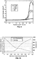
- 238000001000 micrograph Methods 0.000 description 5
- 238000004806 packaging method and process Methods 0.000 description 5
- 239000000123 paper Substances 0.000 description 5
- 239000004033 plastic Substances 0.000 description 5
- 229920003023 plastic Polymers 0.000 description 5
- 229910052709 silver Inorganic materials 0.000 description 5
- 239000004332 silver Substances 0.000 description 5
- 238000012360 testing method Methods 0.000 description 5
- IAZDPXIOMUYVGZ-UHFFFAOYSA-N Dimethylsulphoxide Chemical compound CS(C)=O IAZDPXIOMUYVGZ-UHFFFAOYSA-N 0.000 description 4
- 239000002033 PVDF binder Substances 0.000 description 4
- 239000000654 additive Substances 0.000 description 4
- 230000000903 blocking effect Effects 0.000 description 4
- 230000015556 catabolic process Effects 0.000 description 4
- 239000000470 constituent Substances 0.000 description 4
- 238000005520 cutting process Methods 0.000 description 4
- 238000013461 design Methods 0.000 description 4
- 238000004090 dissolution Methods 0.000 description 4
- 238000005538 encapsulation Methods 0.000 description 4
- 239000004744 fabric Substances 0.000 description 4
- 238000012805 post-processing Methods 0.000 description 4
- 238000006722 reduction reaction Methods 0.000 description 4
- 238000007650 screen-printing Methods 0.000 description 4
- 238000007740 vapor deposition Methods 0.000 description 4
- CITILBVTAYEWKR-UHFFFAOYSA-L zinc trifluoromethanesulfonate Chemical compound [Zn+2].[O-]S(=O)(=O)C(F)(F)F.[O-]S(=O)(=O)C(F)(F)F CITILBVTAYEWKR-UHFFFAOYSA-L 0.000 description 4
- FRZPYEHDSAQGAS-UHFFFAOYSA-M 1-butyl-3-methylimidazol-3-ium;trifluoromethanesulfonate Chemical compound [O-]S(=O)(=O)C(F)(F)F.CCCC[N+]=1C=CN(C)C=1 FRZPYEHDSAQGAS-UHFFFAOYSA-M 0.000 description 3
- RYGMFSIKBFXOCR-UHFFFAOYSA-N Copper Chemical compound [Cu] RYGMFSIKBFXOCR-UHFFFAOYSA-N 0.000 description 3
- 230000002378 acidificating effect Effects 0.000 description 3
- 230000004913 activation Effects 0.000 description 3
- 239000010405 anode material Substances 0.000 description 3
- 230000033228 biological regulation Effects 0.000 description 3
- 229910052802 copper Inorganic materials 0.000 description 3
- 239000010949 copper Substances 0.000 description 3
- 238000002484 cyclic voltammetry Methods 0.000 description 3
- 238000000354 decomposition reaction Methods 0.000 description 3
- 230000003247 decreasing effect Effects 0.000 description 3
- 238000006731 degradation reaction Methods 0.000 description 3
- 238000011161 development Methods 0.000 description 3
- 238000007599 discharging Methods 0.000 description 3
- ZRALSGWEFCBTJO-UHFFFAOYSA-N guanidine group Chemical group NC(=N)N ZRALSGWEFCBTJO-UHFFFAOYSA-N 0.000 description 3
- 238000010348 incorporation Methods 0.000 description 3
- 238000007641 inkjet printing Methods 0.000 description 3
- 238000003475 lamination Methods 0.000 description 3
- 229910052749 magnesium Inorganic materials 0.000 description 3
- 239000011777 magnesium Substances 0.000 description 3
- 238000005259 measurement Methods 0.000 description 3
- 239000002105 nanoparticle Substances 0.000 description 3
- 230000003071 parasitic effect Effects 0.000 description 3
- 239000000843 powder Substances 0.000 description 3
- 238000012545 processing Methods 0.000 description 3
- 238000000518 rheometry Methods 0.000 description 3
- 241000894007 species Species 0.000 description 3
- 238000012546 transfer Methods 0.000 description 3
- 230000007723 transport mechanism Effects 0.000 description 3
- 239000002699 waste material Substances 0.000 description 3
- ZFPGARUNNKGOBB-UHFFFAOYSA-N 1-Ethyl-2-pyrrolidinone Chemical compound CCN1CCCC1=O ZFPGARUNNKGOBB-UHFFFAOYSA-N 0.000 description 2
- CSCPPACGZOOCGX-UHFFFAOYSA-N Acetone Chemical compound CC(C)=O CSCPPACGZOOCGX-UHFFFAOYSA-N 0.000 description 2
- 241001124569 Lycaenidae Species 0.000 description 2
- FYYHWMGAXLPEAU-UHFFFAOYSA-N Magnesium Chemical compound [Mg] FYYHWMGAXLPEAU-UHFFFAOYSA-N 0.000 description 2
- 239000004695 Polyether sulfone Substances 0.000 description 2
- 239000004698 Polyethylene Substances 0.000 description 2
- 239000004642 Polyimide Substances 0.000 description 2
- XUIMIQQOPSSXEZ-UHFFFAOYSA-N Silicon Chemical compound [Si] XUIMIQQOPSSXEZ-UHFFFAOYSA-N 0.000 description 2
- 239000000853 adhesive Substances 0.000 description 2
- 230000001070 adhesive effect Effects 0.000 description 2
- 239000012080 ambient air Substances 0.000 description 2
- 238000000137 annealing Methods 0.000 description 2
- 230000004888 barrier function Effects 0.000 description 2
- 238000005452 bending Methods 0.000 description 2
- NEHMKBQYUWJMIP-UHFFFAOYSA-N chloromethane Chemical compound ClC NEHMKBQYUWJMIP-UHFFFAOYSA-N 0.000 description 2
- 239000011248 coating agent Substances 0.000 description 2
- 238000000576 coating method Methods 0.000 description 2
- 230000000295 complement effect Effects 0.000 description 2
- 230000001419 dependent effect Effects 0.000 description 2
- 230000001627 detrimental effect Effects 0.000 description 2
- 230000003467 diminishing effect Effects 0.000 description 2
- 238000001035 drying Methods 0.000 description 2
- 230000005518 electrochemistry Effects 0.000 description 2
- 239000002001 electrolyte material Substances 0.000 description 2
- 229910021389 graphene Inorganic materials 0.000 description 2
- 238000001453 impedance spectrum Methods 0.000 description 2
- 230000006872 improvement Effects 0.000 description 2
- 239000012535 impurity Substances 0.000 description 2
- 230000010354 integration Effects 0.000 description 2
- 230000014759 maintenance of location Effects 0.000 description 2
- 238000002844 melting Methods 0.000 description 2
- 150000002739 metals Chemical class 0.000 description 2
- 238000002156 mixing Methods 0.000 description 2
- 238000012544 monitoring process Methods 0.000 description 2
- 230000000877 morphologic effect Effects 0.000 description 2
- QJGQUHMNIGDVPM-UHFFFAOYSA-N nitrogen group Chemical class [N] QJGQUHMNIGDVPM-UHFFFAOYSA-N 0.000 description 2
- 239000011255 nonaqueous electrolyte Substances 0.000 description 2
- 239000011368 organic material Substances 0.000 description 2
- 229920000620 organic polymer Polymers 0.000 description 2
- 230000003647 oxidation Effects 0.000 description 2
- HTQOEHYNHFXMJJ-UHFFFAOYSA-N oxosilver zinc Chemical compound [Zn].[Ag]=O HTQOEHYNHFXMJJ-UHFFFAOYSA-N 0.000 description 2
- 238000000059 patterning Methods 0.000 description 2
- 230000010287 polarization Effects 0.000 description 2
- 229920001643 poly(ether ketone) Polymers 0.000 description 2
- 229920006219 poly(vinylidene fluoride-co-hexafluoropropene) Polymers 0.000 description 2
- 229920000728 polyester Polymers 0.000 description 2
- 229920013745 polyesteretherketone Polymers 0.000 description 2
- 229920006393 polyether sulfone Polymers 0.000 description 2
- 229920000573 polyethylene Polymers 0.000 description 2
- 229920001721 polyimide Polymers 0.000 description 2
- 238000002360 preparation method Methods 0.000 description 2
- 230000002035 prolonged effect Effects 0.000 description 2
- 230000009467 reduction Effects 0.000 description 2
- 238000011160 research Methods 0.000 description 2
- 239000000523 sample Substances 0.000 description 2
- 229910052710 silicon Inorganic materials 0.000 description 2
- 239000010703 silicon Substances 0.000 description 2
- 238000007764 slot die coating Methods 0.000 description 2
- 239000000725 suspension Substances 0.000 description 2
- 210000004243 sweat Anatomy 0.000 description 2
- 230000035900 sweating Effects 0.000 description 2
- 229910052727 yttrium Inorganic materials 0.000 description 2
- VWQVUPCCIRVNHF-UHFFFAOYSA-N yttrium atom Chemical compound [Y] VWQVUPCCIRVNHF-UHFFFAOYSA-N 0.000 description 2
- 229940006486 zinc cation Drugs 0.000 description 2
- ZMLPZCGHASSGEA-UHFFFAOYSA-M zinc trifluoromethanesulfonate Chemical compound [Zn+2].[O-]S(=O)(=O)C(F)(F)F ZMLPZCGHASSGEA-UHFFFAOYSA-M 0.000 description 2
- GMGZEOLIKDSQTL-UHFFFAOYSA-N 1,1,3,3-tetramethylguanidine;hydrochloride Chemical compound [Cl-].CN(C)C(N)=[N+](C)C GMGZEOLIKDSQTL-UHFFFAOYSA-N 0.000 description 1
- OBIUJJSQKPGKME-UHFFFAOYSA-N 1,2,3,5-tetrachloro-4-(2,4,6-trichlorophenyl)benzene Chemical compound ClC1=CC(Cl)=CC(Cl)=C1C1=C(Cl)C=C(Cl)C(Cl)=C1Cl OBIUJJSQKPGKME-UHFFFAOYSA-N 0.000 description 1
- 229920000742 Cotton Polymers 0.000 description 1
- 241000283070 Equus zebra Species 0.000 description 1
- KMTRUDSVKNLOMY-UHFFFAOYSA-N Ethylene carbonate Chemical compound O=C1OCCO1 KMTRUDSVKNLOMY-UHFFFAOYSA-N 0.000 description 1
- 229920006370 Kynar Polymers 0.000 description 1
- PWHULOQIROXLJO-UHFFFAOYSA-N Manganese Chemical compound [Mn] PWHULOQIROXLJO-UHFFFAOYSA-N 0.000 description 1
- 229910014351 N(SO2F)2 Inorganic materials 0.000 description 1
- CHJJGSNFBQVOTG-UHFFFAOYSA-N N-methyl-guanidine Natural products CNC(N)=N CHJJGSNFBQVOTG-UHFFFAOYSA-N 0.000 description 1
- 239000004677 Nylon Substances 0.000 description 1
- 239000004743 Polypropylene Substances 0.000 description 1
- VYPSYNLAJGMNEJ-UHFFFAOYSA-N Silicium dioxide Chemical compound O=[Si]=O VYPSYNLAJGMNEJ-UHFFFAOYSA-N 0.000 description 1
- 235000010724 Wisteria floribunda Nutrition 0.000 description 1
- BPKGOZPBGXJDEP-UHFFFAOYSA-N [C].[Zn] Chemical compound [C].[Zn] BPKGOZPBGXJDEP-UHFFFAOYSA-N 0.000 description 1
- 239000006230 acetylene black Substances 0.000 description 1
- 125000002723 alicyclic group Chemical group 0.000 description 1
- 125000000217 alkyl group Chemical group 0.000 description 1
- AZDRQVAHHNSJOQ-UHFFFAOYSA-N alumane Chemical class [AlH3] AZDRQVAHHNSJOQ-UHFFFAOYSA-N 0.000 description 1
- 239000004411 aluminium Substances 0.000 description 1
- RQNWIZPPADIBDY-UHFFFAOYSA-N arsenic atom Chemical class [As] RQNWIZPPADIBDY-UHFFFAOYSA-N 0.000 description 1
- 238000000498 ball milling Methods 0.000 description 1
- 230000015572 biosynthetic process Effects 0.000 description 1
- 238000005266 casting Methods 0.000 description 1
- 239000006182 cathode active material Substances 0.000 description 1
- 239000010406 cathode material Substances 0.000 description 1
- 125000002091 cationic group Chemical group 0.000 description 1
- 238000012512 characterization method Methods 0.000 description 1
- 150000001805 chlorine compounds Chemical class 0.000 description 1
- BOYBOCSCIOGQOZ-UHFFFAOYSA-N chloromethane;2-methylprop-2-enoic acid Chemical compound ClC.CC(=C)C(O)=O BOYBOCSCIOGQOZ-UHFFFAOYSA-N 0.000 description 1
- 229920000891 common polymer Polymers 0.000 description 1
- 230000006835 compression Effects 0.000 description 1
- 238000007906 compression Methods 0.000 description 1
- 239000002482 conductive additive Substances 0.000 description 1
- 239000011231 conductive filler Substances 0.000 description 1
- 239000011370 conductive nanoparticle Substances 0.000 description 1
- 239000000356 contaminant Substances 0.000 description 1
- 238000011109 contamination Methods 0.000 description 1
- 229920001577 copolymer Polymers 0.000 description 1
- 238000005859 coupling reaction Methods 0.000 description 1
- 239000002178 crystalline material Substances 0.000 description 1
- 230000001186 cumulative effect Effects 0.000 description 1
- 125000004122 cyclic group Chemical group 0.000 description 1
- 210000001787 dendrite Anatomy 0.000 description 1
- 238000005137 deposition process Methods 0.000 description 1
- 230000000994 depressogenic effect Effects 0.000 description 1
- VWYHCWVXCWCOPV-UHFFFAOYSA-L dilithium trifluoromethanesulfonate Chemical compound [Li+].[Li+].[O-]S(=O)(=O)C(F)(F)F.[O-]S(=O)(=O)C(F)(F)F VWYHCWVXCWCOPV-UHFFFAOYSA-L 0.000 description 1
- SWSQBOPZIKWTGO-UHFFFAOYSA-N dimethylaminoamidine Natural products CN(C)C(N)=N SWSQBOPZIKWTGO-UHFFFAOYSA-N 0.000 description 1
- 230000003292 diminished effect Effects 0.000 description 1
- 238000003618 dip coating Methods 0.000 description 1
- 230000009977 dual effect Effects 0.000 description 1
- 239000000428 dust Substances 0.000 description 1
- 230000000694 effects Effects 0.000 description 1
- 229920001971 elastomer Polymers 0.000 description 1
- 239000000806 elastomer Substances 0.000 description 1
- 238000003487 electrochemical reaction Methods 0.000 description 1
- 239000008151 electrolyte solution Substances 0.000 description 1
- 239000003822 epoxy resin Substances 0.000 description 1
- 238000005530 etching Methods 0.000 description 1
- 238000001704 evaporation Methods 0.000 description 1
- 230000008020 evaporation Effects 0.000 description 1
- 230000001747 exhibiting effect Effects 0.000 description 1
- 239000007789 gas Substances 0.000 description 1
- 108010025899 gelatin film Proteins 0.000 description 1
- PCHJSUWPFVWCPO-UHFFFAOYSA-N gold Chemical compound [Au] PCHJSUWPFVWCPO-UHFFFAOYSA-N 0.000 description 1
- 229910052737 gold Inorganic materials 0.000 description 1
- 239000010931 gold Substances 0.000 description 1
- 238000007646 gravure printing Methods 0.000 description 1
- 150000004820 halides Chemical class 0.000 description 1
- 231100001261 hazardous Toxicity 0.000 description 1
- 230000036541 health Effects 0.000 description 1
- 230000017525 heat dissipation Effects 0.000 description 1
- BHEPBYXIRTUNPN-UHFFFAOYSA-N hydridophosphorus(.) (triplet) Chemical compound [PH] BHEPBYXIRTUNPN-UHFFFAOYSA-N 0.000 description 1
- 230000002209 hydrophobic effect Effects 0.000 description 1
- 238000002847 impedance measurement Methods 0.000 description 1
- 239000004615 ingredient Substances 0.000 description 1
- 229910010272 inorganic material Inorganic materials 0.000 description 1
- 239000011147 inorganic material Substances 0.000 description 1
- 238000003780 insertion Methods 0.000 description 1
- 230000037431 insertion Effects 0.000 description 1
- 239000012212 insulator Substances 0.000 description 1
- 210000003127 knee Anatomy 0.000 description 1
- 238000004502 linear sweep voltammetry Methods 0.000 description 1
- 239000007791 liquid phase Substances 0.000 description 1
- 229910003002 lithium salt Inorganic materials 0.000 description 1
- 159000000002 lithium salts Chemical class 0.000 description 1
- MCVFFRWZNYZUIJ-UHFFFAOYSA-M lithium;trifluoromethanesulfonate Chemical compound [Li+].[O-]S(=O)(=O)C(F)(F)F MCVFFRWZNYZUIJ-UHFFFAOYSA-M 0.000 description 1
- 238000001459 lithography Methods 0.000 description 1
- 230000005923 long-lasting effect Effects 0.000 description 1
- 229910052748 manganese Inorganic materials 0.000 description 1
- 239000011572 manganese Substances 0.000 description 1
- 238000000691 measurement method Methods 0.000 description 1
- 239000000155 melt Substances 0.000 description 1
- 230000008018 melting Effects 0.000 description 1
- 229940050176 methyl chloride Drugs 0.000 description 1
- 238000000386 microscopy Methods 0.000 description 1
- 230000000116 mitigating effect Effects 0.000 description 1
- QELJHCBNGDEXLD-UHFFFAOYSA-N nickel zinc Chemical compound [Ni].[Zn] QELJHCBNGDEXLD-UHFFFAOYSA-N 0.000 description 1
- 229920001778 nylon Polymers 0.000 description 1
- 238000005457 optimization Methods 0.000 description 1
- 239000005486 organic electrolyte Substances 0.000 description 1
- 239000003973 paint Substances 0.000 description 1
- 230000037361 pathway Effects 0.000 description 1
- 230000000704 physical effect Effects 0.000 description 1
- 229920003223 poly(pyromellitimide-1,4-diphenyl ether) Polymers 0.000 description 1
- 229920000647 polyepoxide Polymers 0.000 description 1
- 238000012667 polymer degradation Methods 0.000 description 1
- 229920006254 polymer film Polymers 0.000 description 1
- 239000002861 polymer material Substances 0.000 description 1
- 238000010094 polymer processing Methods 0.000 description 1
- 229920001155 polypropylene Polymers 0.000 description 1
- 229920002635 polyurethane Polymers 0.000 description 1
- 239000004814 polyurethane Substances 0.000 description 1
- 238000003672 processing method Methods 0.000 description 1
- 230000000750 progressive effect Effects 0.000 description 1
- RUOJZAUFBMNUDX-UHFFFAOYSA-N propylene carbonate Chemical compound CC1COC(=O)O1 RUOJZAUFBMNUDX-UHFFFAOYSA-N 0.000 description 1
- HNJBEVLQSNELDL-UHFFFAOYSA-N pyrrolidin-2-one Chemical compound O=C1CCCN1 HNJBEVLQSNELDL-UHFFFAOYSA-N 0.000 description 1
- 239000000376 reactant Substances 0.000 description 1
- 238000006479 redox reaction Methods 0.000 description 1
- 238000005096 rolling process Methods 0.000 description 1
- 239000012266 salt solution Substances 0.000 description 1
- 230000035945 sensitivity Effects 0.000 description 1
- 229920002050 silicone resin Polymers 0.000 description 1
- 238000004088 simulation Methods 0.000 description 1
- 239000002356 single layer Substances 0.000 description 1
- 229910000679 solder Inorganic materials 0.000 description 1
- 239000007784 solid electrolyte Substances 0.000 description 1
- 239000011343 solid material Substances 0.000 description 1
- 238000001228 spectrum Methods 0.000 description 1
- 239000012798 spherical particle Substances 0.000 description 1
- 230000002269 spontaneous effect Effects 0.000 description 1
- 238000004544 sputter deposition Methods 0.000 description 1
- 239000000126 substance Substances 0.000 description 1
- 238000010408 sweeping Methods 0.000 description 1
- 238000003786 synthesis reaction Methods 0.000 description 1
- 230000036962 time dependent Effects 0.000 description 1
- 210000000707 wrist Anatomy 0.000 description 1
- SZKTYYIADWRVSA-UHFFFAOYSA-N zinc manganese(2+) oxygen(2-) Chemical compound [O--].[O--].[Mn++].[Zn++] SZKTYYIADWRVSA-UHFFFAOYSA-N 0.000 description 1
Images


Classifications
-
- H—ELECTRICITY
- H01—ELECTRIC ELEMENTS
- H01M—PROCESSES OR MEANS, e.g. BATTERIES, FOR THE DIRECT CONVERSION OF CHEMICAL ENERGY INTO ELECTRICAL ENERGY
- H01M10/00—Secondary cells; Manufacture thereof
- H01M10/05—Accumulators with non-aqueous electrolyte
- H01M10/056—Accumulators with non-aqueous electrolyte characterised by the materials used as electrolytes, e.g. mixed inorganic/organic electrolytes
- H01M10/0564—Accumulators with non-aqueous electrolyte characterised by the materials used as electrolytes, e.g. mixed inorganic/organic electrolytes the electrolyte being constituted of organic materials only
- H01M10/0565—Polymeric materials, e.g. gel-type or solid-type
-
- H—ELECTRICITY
- H01—ELECTRIC ELEMENTS
- H01B—CABLES; CONDUCTORS; INSULATORS; SELECTION OF MATERIALS FOR THEIR CONDUCTIVE, INSULATING OR DIELECTRIC PROPERTIES
- H01B1/00—Conductors or conductive bodies characterised by the conductive materials; Selection of materials as conductors
- H01B1/06—Conductors or conductive bodies characterised by the conductive materials; Selection of materials as conductors mainly consisting of other non-metallic substances
- H01B1/12—Conductors or conductive bodies characterised by the conductive materials; Selection of materials as conductors mainly consisting of other non-metallic substances organic substances
- H01B1/122—Ionic conductors
-
- H—ELECTRICITY
- H01—ELECTRIC ELEMENTS
- H01G—CAPACITORS; CAPACITORS, RECTIFIERS, DETECTORS, SWITCHING DEVICES OR LIGHT-SENSITIVE DEVICES, OF THE ELECTROLYTIC TYPE
- H01G11/00—Hybrid capacitors, i.e. capacitors having different positive and negative electrodes; Electric double-layer [EDL] capacitors; Processes for the manufacture thereof or of parts thereof
- H01G11/22—Electrodes
- H01G11/30—Electrodes characterised by their material
- H01G11/46—Metal oxides
-
- H—ELECTRICITY
- H01—ELECTRIC ELEMENTS
- H01G—CAPACITORS; CAPACITORS, RECTIFIERS, DETECTORS, SWITCHING DEVICES OR LIGHT-SENSITIVE DEVICES, OF THE ELECTROLYTIC TYPE
- H01G11/00—Hybrid capacitors, i.e. capacitors having different positive and negative electrodes; Electric double-layer [EDL] capacitors; Processes for the manufacture thereof or of parts thereof
- H01G11/54—Electrolytes
- H01G11/56—Solid electrolytes, e.g. gels; Additives therein
-
- H—ELECTRICITY
- H01—ELECTRIC ELEMENTS
- H01G—CAPACITORS; CAPACITORS, RECTIFIERS, DETECTORS, SWITCHING DEVICES OR LIGHT-SENSITIVE DEVICES, OF THE ELECTROLYTIC TYPE
- H01G11/00—Hybrid capacitors, i.e. capacitors having different positive and negative electrodes; Electric double-layer [EDL] capacitors; Processes for the manufacture thereof or of parts thereof
- H01G11/84—Processes for the manufacture of hybrid or EDL capacitors, or components thereof
- H01G11/86—Processes for the manufacture of hybrid or EDL capacitors, or components thereof specially adapted for electrodes
-
- H—ELECTRICITY
- H01—ELECTRIC ELEMENTS
- H01G—CAPACITORS; CAPACITORS, RECTIFIERS, DETECTORS, SWITCHING DEVICES OR LIGHT-SENSITIVE DEVICES, OF THE ELECTROLYTIC TYPE
- H01G9/00—Electrolytic capacitors, rectifiers, detectors, switching devices, light-sensitive or temperature-sensitive devices; Processes of their manufacture
- H01G9/0029—Processes of manufacture
- H01G9/0032—Processes of manufacture formation of the dielectric layer
-
- H—ELECTRICITY
- H01—ELECTRIC ELEMENTS
- H01G—CAPACITORS; CAPACITORS, RECTIFIERS, DETECTORS, SWITCHING DEVICES OR LIGHT-SENSITIVE DEVICES, OF THE ELECTROLYTIC TYPE
- H01G9/00—Electrolytic capacitors, rectifiers, detectors, switching devices, light-sensitive or temperature-sensitive devices; Processes of their manufacture
- H01G9/004—Details
- H01G9/022—Electrolytes; Absorbents
- H01G9/025—Solid electrolytes
- H01G9/028—Organic semiconducting electrolytes, e.g. TCNQ
-
- H—ELECTRICITY
- H01—ELECTRIC ELEMENTS
- H01G—CAPACITORS; CAPACITORS, RECTIFIERS, DETECTORS, SWITCHING DEVICES OR LIGHT-SENSITIVE DEVICES, OF THE ELECTROLYTIC TYPE
- H01G9/00—Electrolytic capacitors, rectifiers, detectors, switching devices, light-sensitive or temperature-sensitive devices; Processes of their manufacture
- H01G9/004—Details
- H01G9/022—Electrolytes; Absorbents
- H01G9/035—Liquid electrolytes, e.g. impregnating materials
-
- H—ELECTRICITY
- H01—ELECTRIC ELEMENTS
- H01G—CAPACITORS; CAPACITORS, RECTIFIERS, DETECTORS, SWITCHING DEVICES OR LIGHT-SENSITIVE DEVICES, OF THE ELECTROLYTIC TYPE
- H01G9/00—Electrolytic capacitors, rectifiers, detectors, switching devices, light-sensitive or temperature-sensitive devices; Processes of their manufacture
- H01G9/004—Details
- H01G9/04—Electrodes or formation of dielectric layers thereon
- H01G9/042—Electrodes or formation of dielectric layers thereon characterised by the material
-
- H—ELECTRICITY
- H01—ELECTRIC ELEMENTS
- H01G—CAPACITORS; CAPACITORS, RECTIFIERS, DETECTORS, SWITCHING DEVICES OR LIGHT-SENSITIVE DEVICES, OF THE ELECTROLYTIC TYPE
- H01G9/00—Electrolytic capacitors, rectifiers, detectors, switching devices, light-sensitive or temperature-sensitive devices; Processes of their manufacture
- H01G9/145—Liquid electrolytic capacitors
-
- H—ELECTRICITY
- H01—ELECTRIC ELEMENTS
- H01G—CAPACITORS; CAPACITORS, RECTIFIERS, DETECTORS, SWITCHING DEVICES OR LIGHT-SENSITIVE DEVICES, OF THE ELECTROLYTIC TYPE
- H01G9/00—Electrolytic capacitors, rectifiers, detectors, switching devices, light-sensitive or temperature-sensitive devices; Processes of their manufacture
- H01G9/15—Solid electrolytic capacitors
-
- H—ELECTRICITY
- H01—ELECTRIC ELEMENTS
- H01M—PROCESSES OR MEANS, e.g. BATTERIES, FOR THE DIRECT CONVERSION OF CHEMICAL ENERGY INTO ELECTRICAL ENERGY
- H01M10/00—Secondary cells; Manufacture thereof
- H01M10/04—Construction or manufacture in general
- H01M10/0436—Small-sized flat cells or batteries for portable equipment
-
- H—ELECTRICITY
- H01—ELECTRIC ELEMENTS
- H01M—PROCESSES OR MEANS, e.g. BATTERIES, FOR THE DIRECT CONVERSION OF CHEMICAL ENERGY INTO ELECTRICAL ENERGY
- H01M10/00—Secondary cells; Manufacture thereof
- H01M10/05—Accumulators with non-aqueous electrolyte
-
- H—ELECTRICITY
- H01—ELECTRIC ELEMENTS
- H01M—PROCESSES OR MEANS, e.g. BATTERIES, FOR THE DIRECT CONVERSION OF CHEMICAL ENERGY INTO ELECTRICAL ENERGY
- H01M10/00—Secondary cells; Manufacture thereof
- H01M10/05—Accumulators with non-aqueous electrolyte
- H01M10/054—Accumulators with insertion or intercalation of metals other than lithium, e.g. with magnesium or aluminium
-
- H—ELECTRICITY
- H01—ELECTRIC ELEMENTS
- H01M—PROCESSES OR MEANS, e.g. BATTERIES, FOR THE DIRECT CONVERSION OF CHEMICAL ENERGY INTO ELECTRICAL ENERGY
- H01M10/00—Secondary cells; Manufacture thereof
- H01M10/05—Accumulators with non-aqueous electrolyte
- H01M10/058—Construction or manufacture
-
- H—ELECTRICITY
- H01—ELECTRIC ELEMENTS
- H01M—PROCESSES OR MEANS, e.g. BATTERIES, FOR THE DIRECT CONVERSION OF CHEMICAL ENERGY INTO ELECTRICAL ENERGY
- H01M4/00—Electrodes
- H01M4/02—Electrodes composed of, or comprising, active material
- H01M4/36—Selection of substances as active materials, active masses, active liquids
- H01M4/38—Selection of substances as active materials, active masses, active liquids of elements or alloys
- H01M4/381—Alkaline or alkaline earth metals elements
-
- H—ELECTRICITY
- H01—ELECTRIC ELEMENTS
- H01M—PROCESSES OR MEANS, e.g. BATTERIES, FOR THE DIRECT CONVERSION OF CHEMICAL ENERGY INTO ELECTRICAL ENERGY
- H01M4/00—Electrodes
- H01M4/02—Electrodes composed of, or comprising, active material
- H01M4/36—Selection of substances as active materials, active masses, active liquids
- H01M4/48—Selection of substances as active materials, active masses, active liquids of inorganic oxides or hydroxides
- H01M4/483—Selection of substances as active materials, active masses, active liquids of inorganic oxides or hydroxides for non-aqueous cells
-
- H—ELECTRICITY
- H01—ELECTRIC ELEMENTS
- H01M—PROCESSES OR MEANS, e.g. BATTERIES, FOR THE DIRECT CONVERSION OF CHEMICAL ENERGY INTO ELECTRICAL ENERGY
- H01M4/00—Electrodes
- H01M4/02—Electrodes composed of, or comprising, active material
- H01M4/36—Selection of substances as active materials, active masses, active liquids
- H01M4/48—Selection of substances as active materials, active masses, active liquids of inorganic oxides or hydroxides
- H01M4/50—Selection of substances as active materials, active masses, active liquids of inorganic oxides or hydroxides of manganese
- H01M4/502—Selection of substances as active materials, active masses, active liquids of inorganic oxides or hydroxides of manganese for non-aqueous cells
-
- H—ELECTRICITY
- H01—ELECTRIC ELEMENTS
- H01M—PROCESSES OR MEANS, e.g. BATTERIES, FOR THE DIRECT CONVERSION OF CHEMICAL ENERGY INTO ELECTRICAL ENERGY
- H01M4/00—Electrodes
- H01M4/02—Electrodes composed of, or comprising, active material
- H01M4/36—Selection of substances as active materials, active masses, active liquids
- H01M4/48—Selection of substances as active materials, active masses, active liquids of inorganic oxides or hydroxides
- H01M4/52—Selection of substances as active materials, active masses, active liquids of inorganic oxides or hydroxides of nickel, cobalt or iron
- H01M4/523—Selection of substances as active materials, active masses, active liquids of inorganic oxides or hydroxides of nickel, cobalt or iron for non-aqueous cells
-
- H—ELECTRICITY
- H01—ELECTRIC ELEMENTS
- H01M—PROCESSES OR MEANS, e.g. BATTERIES, FOR THE DIRECT CONVERSION OF CHEMICAL ENERGY INTO ELECTRICAL ENERGY
- H01M4/00—Electrodes
- H01M4/02—Electrodes composed of, or comprising, active material
- H01M4/36—Selection of substances as active materials, active masses, active liquids
- H01M4/48—Selection of substances as active materials, active masses, active liquids of inorganic oxides or hydroxides
- H01M4/56—Selection of substances as active materials, active masses, active liquids of inorganic oxides or hydroxides of lead
-
- H—ELECTRICITY
- H01—ELECTRIC ELEMENTS
- H01M—PROCESSES OR MEANS, e.g. BATTERIES, FOR THE DIRECT CONVERSION OF CHEMICAL ENERGY INTO ELECTRICAL ENERGY
- H01M4/00—Electrodes
- H01M4/02—Electrodes composed of, or comprising, active material
- H01M4/64—Carriers or collectors
-
- H—ELECTRICITY
- H01—ELECTRIC ELEMENTS
- H01M—PROCESSES OR MEANS, e.g. BATTERIES, FOR THE DIRECT CONVERSION OF CHEMICAL ENERGY INTO ELECTRICAL ENERGY
- H01M4/00—Electrodes
- H01M4/02—Electrodes composed of, or comprising, active material
- H01M4/64—Carriers or collectors
- H01M4/66—Selection of materials
- H01M4/661—Metal or alloys, e.g. alloy coatings
-
- H—ELECTRICITY
- H01—ELECTRIC ELEMENTS
- H01M—PROCESSES OR MEANS, e.g. BATTERIES, FOR THE DIRECT CONVERSION OF CHEMICAL ENERGY INTO ELECTRICAL ENERGY
- H01M4/00—Electrodes
- H01M4/02—Electrodes composed of, or comprising, active material
- H01M4/64—Carriers or collectors
- H01M4/66—Selection of materials
- H01M4/669—Steels
-
- H—ELECTRICITY
- H01—ELECTRIC ELEMENTS
- H01M—PROCESSES OR MEANS, e.g. BATTERIES, FOR THE DIRECT CONVERSION OF CHEMICAL ENERGY INTO ELECTRICAL ENERGY
- H01M6/00—Primary cells; Manufacture thereof
- H01M6/14—Cells with non-aqueous electrolyte
- H01M6/16—Cells with non-aqueous electrolyte with organic electrolyte
-
- H—ELECTRICITY
- H01—ELECTRIC ELEMENTS
- H01M—PROCESSES OR MEANS, e.g. BATTERIES, FOR THE DIRECT CONVERSION OF CHEMICAL ENERGY INTO ELECTRICAL ENERGY
- H01M6/00—Primary cells; Manufacture thereof
- H01M6/40—Printed batteries, e.g. thin film batteries
-
- H—ELECTRICITY
- H01—ELECTRIC ELEMENTS
- H01M—PROCESSES OR MEANS, e.g. BATTERIES, FOR THE DIRECT CONVERSION OF CHEMICAL ENERGY INTO ELECTRICAL ENERGY
- H01M2220/00—Batteries for particular applications
- H01M2220/30—Batteries in portable systems, e.g. mobile phone, laptop
-
- H—ELECTRICITY
- H01—ELECTRIC ELEMENTS
- H01M—PROCESSES OR MEANS, e.g. BATTERIES, FOR THE DIRECT CONVERSION OF CHEMICAL ENERGY INTO ELECTRICAL ENERGY
- H01M2300/00—Electrolytes
- H01M2300/0017—Non-aqueous electrolytes
- H01M2300/0025—Organic electrolyte
- H01M2300/0045—Room temperature molten salts comprising at least one organic ion
-
- H—ELECTRICITY
- H01—ELECTRIC ELEMENTS
- H01M—PROCESSES OR MEANS, e.g. BATTERIES, FOR THE DIRECT CONVERSION OF CHEMICAL ENERGY INTO ELECTRICAL ENERGY
- H01M2300/00—Electrolytes
- H01M2300/0085—Immobilising or gelification of electrolyte
-
- Y—GENERAL TAGGING OF NEW TECHNOLOGICAL DEVELOPMENTS; GENERAL TAGGING OF CROSS-SECTIONAL TECHNOLOGIES SPANNING OVER SEVERAL SECTIONS OF THE IPC; TECHNICAL SUBJECTS COVERED BY FORMER USPC CROSS-REFERENCE ART COLLECTIONS [XRACs] AND DIGESTS
- Y02—TECHNOLOGIES OR APPLICATIONS FOR MITIGATION OR ADAPTATION AGAINST CLIMATE CHANGE
- Y02E—REDUCTION OF GREENHOUSE GAS [GHG] EMISSIONS, RELATED TO ENERGY GENERATION, TRANSMISSION OR DISTRIBUTION
- Y02E60/00—Enabling technologies; Technologies with a potential or indirect contribution to GHG emissions mitigation
- Y02E60/10—Energy storage using batteries
-
- Y—GENERAL TAGGING OF NEW TECHNOLOGICAL DEVELOPMENTS; GENERAL TAGGING OF CROSS-SECTIONAL TECHNOLOGIES SPANNING OVER SEVERAL SECTIONS OF THE IPC; TECHNICAL SUBJECTS COVERED BY FORMER USPC CROSS-REFERENCE ART COLLECTIONS [XRACs] AND DIGESTS
- Y02—TECHNOLOGIES OR APPLICATIONS FOR MITIGATION OR ADAPTATION AGAINST CLIMATE CHANGE
- Y02E—REDUCTION OF GREENHOUSE GAS [GHG] EMISSIONS, RELATED TO ENERGY GENERATION, TRANSMISSION OR DISTRIBUTION
- Y02E60/00—Enabling technologies; Technologies with a potential or indirect contribution to GHG emissions mitigation
- Y02E60/13—Energy storage using capacitors
-
- Y—GENERAL TAGGING OF NEW TECHNOLOGICAL DEVELOPMENTS; GENERAL TAGGING OF CROSS-SECTIONAL TECHNOLOGIES SPANNING OVER SEVERAL SECTIONS OF THE IPC; TECHNICAL SUBJECTS COVERED BY FORMER USPC CROSS-REFERENCE ART COLLECTIONS [XRACs] AND DIGESTS
- Y02—TECHNOLOGIES OR APPLICATIONS FOR MITIGATION OR ADAPTATION AGAINST CLIMATE CHANGE
- Y02P—CLIMATE CHANGE MITIGATION TECHNOLOGIES IN THE PRODUCTION OR PROCESSING OF GOODS
- Y02P70/00—Climate change mitigation technologies in the production process for final industrial or consumer products
- Y02P70/50—Manufacturing or production processes characterised by the final manufactured product
-
- Y—GENERAL TAGGING OF NEW TECHNOLOGICAL DEVELOPMENTS; GENERAL TAGGING OF CROSS-SECTIONAL TECHNOLOGIES SPANNING OVER SEVERAL SECTIONS OF THE IPC; TECHNICAL SUBJECTS COVERED BY FORMER USPC CROSS-REFERENCE ART COLLECTIONS [XRACs] AND DIGESTS
- Y10—TECHNICAL SUBJECTS COVERED BY FORMER USPC
- Y10T—TECHNICAL SUBJECTS COVERED BY FORMER US CLASSIFICATION
- Y10T29/00—Metal working
- Y10T29/49—Method of mechanical manufacture
- Y10T29/49002—Electrical device making
- Y10T29/49108—Electric battery cell making
- Y10T29/49115—Electric battery cell making including coating or impregnating
Definitions
- This invention relates generally to electrochemical cells, and, more specifically, to ionic liquid gel electrolyte chemistries and methods of making batteries that can be used with devices as single-use or rechargeable power sources.
- thin film, lithium polymer, and semi-printed batteries are the forerunners, though each have significant shortcomings that have limited their widespread adoption.
- Vapor deposited thin film lithium and lithium-ion batteries have low storage capacities and power capabilities due to materials deposition limitations.
- Lithium polymer batteries have leveraged the rapid advancements of pouch cell battery manufacturing, but like thin film lithium and lithium-ion batteries, are plagued by stringent hermetic encapsulation requirements due to its sensitivity to contamination from the environment.
- Semi-printed batteries often utilize a liquid electrolyte, adding cell geometry and manufacturing complexities.
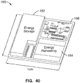
- microdevices need power sources with footprints less than 1 cm 2 and thicknesses on the order of a few mm or less, that can supply power in the range of microwatts ( ⁇ W) to milliwatts (mW), depending on the application.
- ⁇ W microwatts
- mW milliwatts
- the need for a micropower source that can satisfy the power requirements of such wireless devices and with comparable dimensions has incited a surge of research within the fields of microfabrication, energy harvesting, and energy storage.
- the microenergy storage devices currently being considered are microbatteries and microcapacitors.
- microbattery chemistries may be similar to macrobattery chemistries, macrobattery configurations, packaging, and post-processing are not feasible below the centimeter scale.
- microbattery researchers have focused heavily on integrating microbatteries directly onto the same substrates as the devices they are powering.
- US5643490 discloses a polymer solid electrolyte composition which is free from electronic conduction and which has a high ionic conductivity even at temperatures near to room temperature and has good film-forming properties, mechanical strength and flexibility.
- the composition comprises an organic polymer having an alkyl quaternary ammonium salt structure, a nitrogen-containing, heterocyclic quaternary ammonium salt and a metal salt.
- the organic polymer preferably has an alkyl quaternary ammonium salt structure at the end of the side chain of the polymer or in the main chain thereof, such as polydimethylaminoethyl methacrylate methyl chloride quaternary salt, polydimethylaminopropylmethacrylamido methyl chloride quaternary salt, poly(N,N-dimethyl-3-pyrrolinium chloride), etc.
- the nitrogen-containing, heterocyclic quaternary ammonium salt e.g., alkylpyridinium halides
- the metal salt e.g., aluminium halides
- EP2071584 discloses a polymer electrolyte which comprises an ionic liquid (A) and a block copolymer (B) as essential ingredients, which block copolymer (B) comprises one or more of polymer block(s) (P) being compatible with (A) and one or more of polymer block(s) (Q) being incompatible with (A).
- (A) and (P) mutually dissolve each other to form one phase (X), and (Q) forms a phase (Y) being incompatible with phase (X), and phase (X) and phase (Y) are mutually micro phase separated.
- the polymer electrolyte of the present invention shows practical ion conductivity, is excellent in retention of ionic liquid, and moreover, is also excellent in heat resistance and mechanical strength.; Furthermore, the electrochemical device and actuator element of the invention are swiftly displaced in accordance with application of a voltage, and can be actuated stably for a long period due to the liquid-retaining property and mechanical strength of the polymer electrolyte used, and, therefore, can suitably be used in the fields of medical instruments, micro-machines, industrial robot, personal robot, etc.
- US2003211389 discloses an ambient temperature molten salt as non-aqueous electrolyte.
- the molten salt comprises a cation of a guanidine moiety and an anion.
- the cation is selected from alkyl groups, alicyclic groups, or aromatic groups attached asymmetrically to guanidine.
- An exemplary salt is tetramethylguanidinimum bis-trifluoromethanesulfonyl imide, which is liquid at ambient temperature and only slightly soluble in water.
- the salt is prepared by bringing together two aqueous salt solutions, one containing tetramethylguanidine hydrochloride, and the other containing lithium bis-trifluoromethanesulfonyl imide.
- the electrolyte is useful with electrochemical devices such as primary and secondary electrochemical cells and capacitors, such as of the electrolytic and electrolytic/electrochemical hybrid types.
- EP1449886 discloses an inexpensive and durable polymer electrolyte composition exhibiting high ionic conductivity even in the absence of water or a solvent, characterized by comprising a molten salt and an aromatic polymer having a carbonyl bond and/or a sulfonyl bond in the main chain thereof and containing a cation exchange group.
- the aromatic polymer is preferably an aromatic polyether sulfone having a specific structural unit and containing a cation exchange group, an aromatic polyether ketone having a specific structural unit and containing a cation exchange group, or an aromatic polyether sulfone block copolymer and/or an aromatic polyether ketone block copolymer, the block copolymers comprising a hydrophilic segment containing a cation exchange group and a cation exchange group-free hydrophobic segment.;
- the polymer electrolyte composition containing the block copolymer as an aromatic polymer exhibits high structural retention even in high temperatures.
- US2009075176 discloses a solid polymer electrolyte material that is ionically conductive, mechanically robust, and can be formed into desirable shapes using conventional polymer processing methods.
- An exemplary polymer electrolyte material has an elastic modulus in excess of 1x10 6 Pa at 90 degrees C. and is characterized by an ionic conductivity of at least 1x10 -5 Scm -1 at 90 degrees C.
- An exemplary material can be characterized by a two domain or three domain material system.
- An exemplary material can include material components made of diblock polymers or triblock polymers.
- the present invention can be applied to improve Li-based batteries by means of enabling higher energy density, better thermal and environmental stability, lower rates of self-discharge, enhanced safety, lower manufacturing costs, and novel form factors.
- US 2009/246625 discloses lithium-ion batteries in general and more particularly lithium-ion batteries based on aligned graphene ribbon anodes, V 2 O 5 graphene ribbon composite cathodes, and ionic liquid electrolytes.
- the lithium-ion batteries have excellent performance metrics of cell voltages, energy densities, and power densities.
- US 2009/173632 discloses a nonaqueous electrolyte cell-oriented electrode (10) in which an electrode active material layer (12) formed on a collector (1) has a density gradient developed with a gradient of a varied concentration of a solid along a thickness from a surface of the electrode active material layer (12) toward the collector (1), and a gel electrolyte cell-oriented electrode (30) in which an electrode active material layer (32) formed on a collector (1) has a density gradient developed with (a) gradient(s) of (a) varied concentration(s) of one or both of an electrolyte salt and a film forming material along a thickness from a surface of the electrode active material layer (32) toward the collector (1).
- US 2006/210873 discloses pyrrolidinium based room temperature ionic liquids, and phosphorous and arsenic analogues, used as electrolytes in energy storage devices including secondary lithium batteries, supercapacitors and asymmetric battery-supercapacitors.
- the electrolytes preferably contain lithium ions as the charge-carrying species.
- the electrolytes are in a liquid state at the operating temperature.
- Nickel-zinc systems have the problem that zinc dendrites grow, and the shape of the electrode changes during cycling, thus reducing cycle life.
- Rechargeable alkaline manganese cells and zinc-silver oxide cells have the same problem.
- Lithium-ion and lithium polymer systems require strict charge and discharge regulation and pose flammability risks.
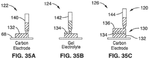
- a polymer is swelled with a room temperature ionic liquid electrolyte to form a non-aqueous gel to replace the traditional alkaline and acidic liquid electrolyte (and separator) of a zinc-metal oxide battery.
- a printed battery is fabricated from an ionic liquid gel electrolyte sandwiched between a zinc electrode and a metal oxide electrode.
- an electrochemical cell comprises an anode layer; a cathode layer; and a non-aqueous gel electrolyte layer coupled to the anode layer and cathode layer; wherein the electrolyte layer provides physical separation between the anode layer and the cathode layer and comprises a polymer into which at least one ionic liquid and an electrolyte salt have been imbibe.
- the electrolyte layer comprising a composition configured to provide ionic communication between the anode layer and cathode layer by facilitating transmission of multivalent ions between the anode layer and the cathode layer.
- electrolyte configured to provide physical separation between an anode and the cathode of an electromechanical cell.
- the electrolyte includes a room temperature ionic liquid electrolyte imbibed into a polymer to form a non-aqueous gel, wherein the electrolyte is configured to provide ionic communication between the anode and cathode by facilitating transmission of multivalent ions across the electrolyte.
- a further aspect of this presentation is a method of fabricating an electrochemical cell comprising the steps of: providing a first electrode ink and a second electrode ink; providing liquid electrolyte ink; printing a first electrode layer of the first electrode ink; printing a layer of electrolyte ink; and printing a second electrode layer of second electrode ink.
- the layer of electrolyte ink provides physical separation between the first electrode layer and second electrode layer to form an electrochemical cell, and is configured to provide ionic communication between the first electrode layer and second layer by facilitating transmission of multivalent ions between the first electrode layer and the second electrode layer.
- negative electrode and “anode” are both used to mean “anode.”
- positive electrode and “cathode” are both used to mean “cathode.”
- Ionic liquids are defined as a class of liquids that are organic salts with low melting points (below 100°C). Ionic liquids have properties that include high ionic conductivity, very good electrochemical and temperature stability, and negligible vapor pressure. These enhanced properties and environmental benefits have attracted diverse attention to room temperature ionic liquids as potential replacements of volatile solvents and materials in manufacturing, chemical reactions, separation, and electrolytes, to name a few. When ionic liquids are incorporated into polymer gels, they can form electrolytes that have liquid-like ion transport properties a few orders of magnitude greater than other polymeric or solid-state electrolyte systems.
- Such ionic liquid gel electrolytes can also be structurally robust and can maintain physical separation between the electrodes of an electrochemical cell even under compression. Furthermore, in ambient environments and room temperature conditions, the gel does not dry out or "sweat" as the ionic liquids are negligibly volatile.
- Multivalent is herein defined as an atomic or molecular species carrying more than one full charge.
- Non-aqueous is herein defined as a system that is largely free of the presence of water, except in trace amounts as a residual contaminant.
- the power behavior of a battery can also be characterized by its rate performance, and is evaluated by the time (in hours) it takes to deplete a device of its maximum storage capacity (C). Note that this terminology can be confusing, as C is also used to represent Coulombs and should not be confused when referred to as a rate of charge or discharge. For example a battery that took 10 hours to completely drain was discharged at a C/10 rate, while a quick discharge of 2C means the battery was depleted in a half hour.
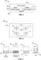
- FIG. 1 is a schematic cross-section of an electrochemical cell 10 according to an embodiment of this presentation.
- the cell 10 comprises a cathode 14 and anode 16 separated by a electrolyte layer 12.
- current collectors 18 may be positioned at the open sides of the anode 16 and cathode 14 to provide proper electrical contact with load 20. It is appreciated that the current collectors 18 are an optional component, and the cell 10 may comprise other configurations with or without current collectors 18.
- the electrochemical cell 10 can be attached to a circuit 22 to do work on an outside load 20.
- the electrochemical cell 10 is a battery cell.
- the electrochemical cell 10 is a rechargeable battery cell.
- the electrochemical cell 10 may comprise a capacitor.
- the electrochemical cell 10 may be fabricated using any of the fabrication methods described below to comprise a number of different structural arrangements.
- the electrodes may be oriented in a stacked configuration as shown in FIG. 1 , or may comprise a 2-dimensional planar configuration as shown in the cell 30 of FIG. 2 .
- cell 30 comprises an anode 16 positioned adjacent cathode 14 on substrate 68.
- Current collectors 18 may be use to provide electrical contact between the anode 16, cathode 14, and the substrate.
- the gel electrolyte 32 encapsulates, and provides separation between, the anode 26 and cathode 14.
- the device 10 of FIG. 1 may also be disposed over a substrate 68 as shown in FIG. 2 .
- a device 40 may comprise a custom connection of an array of batteries 10 coupled to achieve tailored voltage, capacity, energy density, power density output.
- the individual cells may be patterned as stacked sandwich (each cell 10 patterned one on top of other, not shown), or the cells 10 can be patterned in an open adjacent sandwich configuration where electrodes are adjacent to each other as shown in FIG. 3 .
- Positive and negative leads of each battery are accessible on a substrate surface and can be connected via connectors 42, which may comprise a conductive ink.
- the conductive ink 42 may be deposited using a variety of deposition methods, as will be further detailed below, such as ink jet printing, screen printing, flexographic printing, slot die coating, or the like.
- connections 42 may be made via a foil connection (e.g. aluminum, stainless steel, nickel foil, etc.) using foil die cutting, cold foil or hot foil printing methods.
- a foil connection e.g. aluminum, stainless steel, nickel foil, etc.
- connections 42 may be fabricated via elastomeric connectors (ZEBRA, ACF tape), or via clamp connections, probe connections, wire bonding, etc.
- Cells 10 may be connected so all cells are connected in series (positive leads of one cell are connected to negative leads of other cells) to get multipliers of cell voltages (i.e. one cell is 1.5V, two cells is 3V).
- Cells 10 may be connected so all cells are connected in parallel (positive leads of one cell are connected to positive leads of other cell) to get multipliers of cell capacity (i.e. One cell has 5 mAh, two cells output 10 mAh). Mixed configurations of series and parallel connections may also be made to get custom voltage and capacity output.
- each cell 10 may can vary, e.g. from dots ranging from 1 to 5000 ⁇ m diameters, to modules from 0.25 to 500 cm 2 , to large sheets from 0.05 to 1,000 m 2 .
- Stacking of cells may also be used to achieve custom voltage and parallel configurations.
- cells may be stacked one on top of other by placing positive panel of one battery in contact with the negative panel of another battery.
- stacked cells may be separated by an insulator layer and an external bus line can be used to connect positive terminals of cells (e.g. run down the side of battery).
- the gel electrolyte 12, 32 may be used as both a separator and structural material (e.g. thickness/composition may be varied to provide additional structural integrity, or may be used to encapsulate cell as shown in FIG. 2 ).
- the structural gel layer 12 may also be used to create non planar form factor batteries, e.g. the gel electrolyte may be structured to build up walls in which a trench is formed and back fill trench with other materials, such as an electrode.
- the electrolyte layer 12, 32 is a gel electrolyte as shown in the close-up view of electrolyte layer in FIG. 1 .
- the gel electrolyte 12 contains salt cations 24, (Zn2+), and salt anions and ionic liquid anions 28, the ionic liquid cations 26, which are imbibed in a polymer (dark lines).
- the gel electrolyte has a polymer network into which an ionic electrolyte liquid has been imbibed.
- the polymer in the network is poly(vinylidene fluoride-co-hexafluoropropene) PVDF-HFP), PVDF and associated other copolymers, PVA, PEO etc.
- Exemplary liquid electrolytes include a class of materials known as ionic liquids.
- One exemplary ionic liquid comprises 1-butyl-3-methylimidazolium trifluoromethanesulfonate [C 9 H 15 F 3 N 2 O 3 S].
- An electrolyte salt appropriate for the divalent or multivalent ions that are to be transported through the electrolyte gel is dissolved in the ionic liquid.
- the salt is a zinc salt such as zinc trifuoromethanesulfonate [Zn(CF 3 SO 3 ) 2 ], also known as zinc triflate or zinc bis(trifluoromethanesulfonate).
- the salt may also comprise other metals having multivalent ions, such as aluminum, magnesium, yttrium, or combination of the above.
- the ionic liquids suitable for electrochemistry have low electrical conductivity ( ⁇ 5 mS/cm), large electrochemical stability windows (>1 V), ability to dissolve salts, and viscosities compatible with desired processing methods, and may comprise cations such as imidazolium variants, pyrrolidinium variants, ammonium variants, pyridinium variants, piperidinium variants, phosphonium variants, and sulfonium variants, and anions such as chlorides, tetrafluoroborate (BF 4 - ), trifluoroacetate (CF 3 CO 2 - ), trifluoromethansulfonate (CF 3 SO 3 - ), hexafluorophosphate (PF 6 - ), bis(trifluoromethylsulfonyl)amide (NTf 2 - ), bis(fluorosulfonyl)imide (N(SO 2 F) 2 - ). Further distinctions in electrochemical, conductivity, and viscosity properties can be
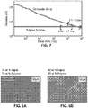
- the liquid electrolyte has an ionic conductivity larger than 1 mS/cm, and preferably ranging between 2 mS/cm and 3.5 mS/cm, and more preferably between 2.3 mS/cm and 2.7 mS/cm.
- an ionic liquid gel electrolyte has an ionic conductivity larger than 0.01 mS/cm, or preferably ranging between 0.03 and 3.5 mS/cm, and more preferably between 0.3 mS/cm and 2.7 mS/cm.
- the liquid electrolyte has a zinc salt concentration between 0.2 and 0.75 M in ionic liquid, and preferably between 0.4 and 0.75 M, and more preferably between 0.45 and 0.65 M.
- a liquid electrolyte having a salt concentration between 0.3 to 0.75M has an ionic conductivity ranging between 2.3 mS/cm and 2.7 mS/cm.
- a liquid electrolyte having a salt concentration between 0.4 to 0.75M has an ionic conductivity above 2.3 mS/cm.
- the preferred zinc salt concentration in the ionic liquid can also be defined as the % of salt with respect to its solubility limit.
- the solubility limit of the zinc salt within the ionic liquid is defined as the concentration of salt added to the ionic liquid at which no more zinc salt can be dissolved.
- the preferred zinc salt concentration is between 25% and 100% of its solubility limit, and preferably between 50% and 95% of its solubility limit, and more preferably between 60% and 88% of its solubility limit.
- the ionic liquid electrolyte concentration in the polymer gel can be defined as % weight of ionic liquid electrolyte in the polymer gel.
- the preferred % weight of ionic liquid electrolyte to polymer is greater than 20%, and preferably ranging between 25% and 90%, and more preferably between 40 and 85%.
- the gel electrolyte layer 12 acts as a physical and electronic separator between the anode 16 and the cathode 14. Despite having mechanical properties similar to a solid material, the gel electrolyte 12 has ion transport properties very similar to a liquid electrolyte.
- ionic liquid gel electrolytes of this presentation have reduced flammability and less hazardous in comparison to typical organic and corrosive electrolytes, making them inherently safer than traditional electrolytes used in commercial systems, especially in conditions of puncture (from nails, bullets, and other sharp objects) ripping, cutting, and other physical damage. Additionally, ionic liquid gel electrolytes are unique in that ionic liquids have negligible vapor pressure and therefore do not evaporate or leak away even under prolonged use. By eliminating the problems of evaporation and leaking (also known as "sweating"), of the liquid component in the gel electrolyte, expensive and complicated hermetic packaging is not needed, thus simplifying processing and reducing the cost of the battery system enormous.
- the anode 16 comprises a metal which emits multivalent ions when undergoing an oxidation reaction with the ionic liquid electrolyte.
- a metal which emits multivalent ions when undergoing an oxidation reaction with the ionic liquid electrolyte.
- zinc metal forms zinc ions of divalent charge as a result of an oxidation reaction with the ionic liquid electrolyte.
- the anode 16 may also comprise aluminum, magnesium, yttrium, or combination of metals that may include some or all of zinc, aluminum, and magnesium metals, or the like.
- the anode material composition may also comprise of multiple morphological features (e.g. zinc flakes and spherical particles and nanoparticles) to increase electrochemical capacity.
- multiple morphological features e.g. zinc flakes and spherical particles and nanoparticles
- the cathode 14 has, as a major component, a metal oxide.
- the cathode 14 may comprise vanadium pentoxide (V 2 O 5 ), manganese dioxide (MnO 2 ) particles, cobalt oxide (CoO x ) particles, lead oxide (PbO x ) particles, or the like.
- the cathode 14 has, as a significant component, particles of any metal oxide that can absorb and release ions that come from the anode.
- the cathode 14 also includes, as a component, a polymer binder, and optionally, electronically-conductive particles (e.g. high surface area carbons, activated carbons, or conductive nanoparticles), and optionally rheology-enhancing particles and polymers (e.g. titanium oxide powder and silica particles).
- electronically-conductive particles e.g. high surface area carbons, activated carbons, or conductive nanoparticles
- rheology-enhancing particles and polymers e.g. titanium oxide powder and silica particles.
- Cathode 14 composition may also be varied to utilize alternative morphological forms of the conductive additives (e.g. graphites and flakey conductive particles) to provide better electrode conductivity and electrochemical properties for thick films > 15 ⁇ m.
- conductive additives e.g. graphites and flakey conductive particles
- the cathode 14 materials be matched with appropriate anode 16 materials. It is important that the cathode 14 contains, as a significant component, materials that can transfer and transmit ions that come from the anode through a combination of oxidation and reduction reactions.
- the oxidation and reduction reactions for a cell 10 as shown in FIG. 1 occur as provided in Equations 1 and 2 below: Zn ⁇ ⁇ Zn 2 + + 2 e ⁇ 2 e ⁇ + 2 MnO 2 ⁇ Zn 2 + ⁇ ⁇ Zn 2 + + 2 MnO 2
- thermodynamic pairing of the anode and cathode materials form a desired electrochemical potential, manifested in a measured cell voltage.
- a zinc anode 16 may be coupled with a MnO 2 cathode, and the typical cell voltage ranges between 1.1-1.6V.
- current collectors 18 are positioned adjacent to, and in electronic communication with the cathode 14 and anode 16.
- Examples of useful current collectors 18 include, but are not limited to, stainless steel, zinc, gold, aluminum, and nickel.
- aluminum and nickel current collectors are contemplated, e.g. foils, nanoparticle ink, composite slurry, electrodeposited coating, and vapor deposited metal.
- Cold foil printing, hot foil printing, or kiss-cut die cutting may also be used to pattern metal foil conductive traces on substrates (such as paper, plastic, fabric). These processes are highly scalable, cost-effective, and high throughput methods for patterning metal foils on non-conductive substrates or backings.
- Foil current collectors 18 would preferably be used 1) in situations where high amounts of bending and creasing and ruggedness are desired, 2) if paper/plastic/fabric substrates are used to eliminate an ink printing step, or 3) low cost applications.
- substrates 68 that can be used to support printing of the electrochemical cell.
- substrates include, but are not limited to, paper (e.g. cardstock or different types/weaves/thicknesses of paper), polymeric or plastic materials (e.g. polyethylene tetrephthalate or polyester (PET), polyethylene, polypropylene, Kapton, polyimide, polyester ether ketone (PEEK), polyurethane, polydimethysiloxane or other silicone resins), fabric of various weaves and meshes (e.g. nylon, cotton, denim) silicon, printed circuit board (e.g. cured epoxy resin substrates, FR4, and flexible circuit boards), glass, metal foil, or combination thereof (e.g.
- the substrate is a material that can be folded into any shape as required for the application.
- a device such as a microprocessor or a MEMS device can be used as the substrate 68. Any of the substrates mentioned above may also have an adhesive backing that will allow for integration of battery onto a surface.
- the substrate 68 and electrode layers are preferably configured to withstand bending and levels of curvature from increasing to large curvature radii (e.g. wrist watch curvatures, and curvatures experienced in rolling processes).
- the gel electrolyte 12 may also comprise of component compositions configured to withstand environmental levels of stability.
- cell 10, 30 may withstand high temperatures, e.g. up to 150°C for extended exposure (without polymer degradation), and even higher temps (like solder temperatures, e.g. 200°C to 300°C) for very short amounts of time (several seconds).
- Cell 10, 30 may withstand low temperatures, e.g. down to -20°C for consumer electronics and down to -40°C for industrial applications, and low and high humidity.
- Additional packaging may also be provided with encapsulation types and methods, such as: dip coating in polymers and/or elastomers such as silicone, single sided printing of encapsulation ink material, double sided printing of encapsulation ink material, hot lamination (the cell 10 of this presentation was tested to withstand the high pressure and temperature associated with this process), polymer lamination with an adhesive, metal foil pouches hot pressed at edges, hard packages, e.g. metal cases, and conventional battery packages.
- encapsulation types and methods such as: dip coating in polymers and/or elastomers such as silicone, single sided printing of encapsulation ink material, double sided printing of encapsulation ink material, hot lamination (the cell 10 of this presentation was tested to withstand the high pressure and temperature associated with this process), polymer lamination with an adhesive, metal foil pouches hot pressed at edges, hard packages, e.g. metal cases, and conventional battery packages.
- One or more of the various cell 10 layers may be formulated into an ink for fabricating an electrochemical cell by printing at least some of the layers. Desirable materials can be mixed together to form, for example, solutions, suspensions, melts, or slurries, which can be used as "ink" in the printing process.
- Various deposition methods may be employed, e.g. direct write printing, screen printing (e.g. Atma, M&R, Colt), flexographic printing (Dai's Machinery, Line O Matic), gravure printing, dispenser printing, ink jet printing (e.g. Fuji Dimatix), slot die coating.
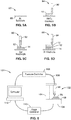
- FIG. 4 and FIGS. 5A through 5D illustrate a method of printing a microbattery using dispenser printing in accordance with this presentation. It is appreciated that other printing/deposition methods may also be used, and that the direct write dispensing method of FIGS. 4 and 5A through 5D are illustrated for exemplary purposes only.
- Direct write dispenser printing comprises a method for additively depositing a variety of materials, including slurries, solutions, and suspensions, generally referred to as "inks.”
- Direct write dispenser printing is a flow-based method of direct write patterning with the ability to deposit inks at room temperature and ambient conditions, all the while generating negligible materials waste and requiring minimal environmental overhead. In comparison to conventional microfabrication techniques, which utilize subtractive processes such as lithography and etching, the number of process steps, energy demanded, and waste generated is significantly less.
- the material compositions of this presentation may be printed on to various surfaces using the dispenser printer system 100 and printer 102 shown in FIG. 6 .
- the ink is loaded into a syringe 66, extruded through a hollow needle of predetermined dimensions, and written onto a substrate 68 via a succession of drops, or "shots.”
- the drop size is determined by the needle's dimensions, ink rheology, and applied pressure.
- the resulting printed film 70 morphology depends on the dimensions of the extruded drops as well as the traversing distance, speed, and time between shots.
- Pneumatic pressure is applied using a controller 110 (e.g. Musashi ML-808FX) that is capable of 2 - 50 kPa output.
- Disposable syringe needles 66 of 16 - 30 Ga (0.15 to 1.35 mm inner diameter) are used to print the inks; tips with inner diameters as small as 0.05 mm can be fabricated by pulling capillary glass tubes using a glass pipette puller.
- tips with different needle sizes may be used according to the composition of the layer being deposed and the desired layer dimensions.
- the smallest diameter needle that a slurry can be consistently printed through must be at least an order of magnitude larger than its largest particles.
- preparation may include a combination of ball milling the particles, physical mixing (magnetic stirrers, paint shakers, vibrating surfaces) and ultrasonic mixing (with a water bath or wand).
- the dispenser printer is able to process a variety of inks into a range of printed feature sizes. All the equipment is controlled and automated through computer 12 and software implemented on a personal computer.
- FIG. 4 illustrates ink preparation process in accordance with this presentation.
- a gel polymer network is provided.
- the polymer in the network is poly (vinylidene fluoride-co-hexafluoropropene) PVDF-HFP).
- the active particles 62 are mixed with the gel polymer 60 to create the ink 64.
- the active particles may vary according to the desired layer that is being printed (e.g. gel electrolyte 12, anode 16, cathode 14 or current collector 18 (if printed).
- solvents may also be added to change the rheology of the ink or change the working time of the ink so it is more compatible with different printing processes, for example, n-methyl-2-pyrrolidone (NMP), Dimethyl Sulfoxide (DMSO), 2-Pyrrolidone, N-ethyl-2-pyrrolidone (NEP), Dimethyl Formamide (DMF), or Acetone.
- NMP n-methyl-2-pyrrolidone
- DMSO Dimethyl Sulfoxide
- NEP 2-Pyrrolidone
- N-ethyl-2-pyrrolidone N-ethyl-2-pyrrolidone
- DMF Dimethyl Formamide
- Acetone Acetone
- the ink 64 is then placed in a syringe needle 66 at step 58 to print the desired layer 70.
- FIGS. 5A through 5D show an exemplary method for fabricating a printed cell in accordance with this presentation.
- a substrate 68 e.g. Nickel
- a current collector (not shown) may be printed onto the substrate.
- the first electrode layer 14 e.g. MnO 2 cathode
- Electrode layer 14 is printed onto the substrate 68 as a first ink dispenser 90 passes over the substrate 68.
- the first electrode layer 14 is deposited on top of that layer.
- a gel layer 12 is printed onto the first electrode layer 14 as a second ink dispenser 86 passes over the first electrode layer 12.
- the electrolyte 12 is a gel electrolyte, preferably comprising ionic liquids mixed with a polymer network into which the electrolyte liquid has been imbibed.
- An electrolyte salt appropriate for the divalent/ multivalent ions that are to be transported through the electrolyte is dissolved in the ionic liquid.
- a second electrode layer 16 (e.g. zinc anode) is printed onto the electrolyte layer 12 as a third ink dispenser 94 passes over the electrolyte layer 12.
- the first electrode layer 14 can be either a positive electrode or a negative electrode
- the second electrode layer 16 is the opposite type from the first electrode 14. That is, if the first electrode 14 is a positive electrode, then the second electrode 16 is a negative electrode, and vice versa. Materials for positive electrodes and negative electrodes have been discussed above.
- printable materials for electrodes are slurries of active electrode material particles mixed with a polymer binder(s), a removable solvent, and optional additives.
- cathode chemistries may comprise a metal oxide such as vanadium pentoxide particles or manganese dioxide particles or both kinds of particles as the active cathode material particles.
- the anode chemistries have zinc particles as the active anode material particles.
- the electrochemical cell 10 not all layers of the electrochemical cell 10 are necessarily printed layers. It is possible to replace one or more printed layers with pre-formed films.
- a zinc foil is used for the negative electrode layer instead of printing the layer with a slurry that contains zinc particles.
- the current collectors may comprise a cold or hot foil printed aluminum foil or vapor deposited metal traces. It is also contemplated that the layers may use other deposition methods, such as coating, etc.
- the layer can be dried. Each subsequent layer is deposited in the desired arrangement and then dried. The drying process removes the solvents that may be components of the slurries used in one or more layers, thus leaving a layer that is a solid, layered film. After all layers are arranged, the entire electrochemical cell structure may be dried to remove any residual evaporative solvents. In one arrangement, a layer or the cell structure is dried at room temperature for about 1-15 minutes and then at 60°-90°C for about 3-30 minutes. In another arrangement, a layer or the cell structure is dried using a vacuum oven. In yet another arrangement, a layer or the cell structure is dried using an infrared or heat lamp.
- the substrate 68 can be removed after the electrochemical cell has been fabricated.
- the printable zinc electrochemical cell 10 of this presentation offers several unique advantages.
- One important advantage is that the printing materials and methods for fabricating electrochemical cells, as described above, can be performed at room temperature and under ambient conditions. That is, no special vacuum or forming gas atmosphere is used to fabricate the cells.
- Thin film battery vapor deposition technology requires a high temperature (> 400°C) annealing step to form crystalline phases of the thin-film deposited electrodes.
- Such ambient conditions make it possible to consider manufacturing, materials, and process options that have not been possible before. For example, temperature-sensitive substrates such as polymer films or paper can be used as there is no high-temperature annealing step in the process.
- the thicknesses of such electrode films can be no more than a few microns, severely limiting the energy storage capacity with respect to the footprint area of the battery.
- the printable electrochemical cells 10 of this presentation can be printed with much thicker electrodes - at least one to two orders of magnitude thicker than thin film microbatteries - and therefore can achieve much higher areal energy densities.
- This rechargeable battery has a nominal voltage between 1.1 - 1.6V depending on the cathode electrode chemistry, and may be operated between 0.7 - 3 V.
- FIG. 7 illustrates the viscosity of a slurry having representative formula for a battery electrode and polymer solution as a response to shear rates applied to the inks.
- the polymer solution is composed of a representative formula for the gel electrolyte.
- the viscosities of the inks were measured with respect to varying shear rates applied by a Rheometric ARES rheometer [TA Instruments].
- the polymer solution displays a relatively constant viscosity for the shear rates applied, demonstrating Newtonian behavior (where the viscosity is insensitive to changes in shear rate).
- shear rates greater than 0.2 1/s the composite slurry ink viscosity decreases linearly with increasing shear rate on a log-log plot.
- the minimum and maximum shear rates applied to the ink by the printer are determined and then related to the corresponding dimensions of the printed feature. This was calculated by measuring the flow rate of ink through the smallest and largest syringe tips as a function of applied pressure.
- the ranges of shear rates and corresponding printed feature sizes applied by the dispenser printer are bracketed for both inks.
- the polymer electrolyte solution extruded from a 16 gauge needle was visually recorded with an orthogonally mounted camera, and then the drop volume was determined using image analysis software.
- the volume of ink was approximated as 1.18 mm 3 , with the shear rate experienced by the ink under these conditions was 491.9 1/s, resulting in a dot pitch of 150 ⁇ m.
- This experiment was repeated for the smallest and largest gauge disposable needles available that could extrude the ink (between 16 - 30 gauge, respectively), and with the lowest and highest pneumatic pressures applied by the controller.
- Viscosity data shown in FIG. 7 are specific to dispenser printing processes. Viscosity may vary depending on the deposition process that is used, e.g. the desired viscosity would vary for screen printing or other processes.
- BMIM+Tf- 1- butyl-3-methylimidazolium trifluoromethanesulfonate
- zinc salt zinc trifluoromethanesulfonate
- ionic liquids and salt pairs may also be considered for this electrochemical system; for example, ionic liquids with reduced viscosities and more stable anions could be used for significant improvements in performance.
- the electrochemical properties of the BMIM + Tf - ionic liquid with zinc salt concentrations varying between 0 - 0.75 M were compared.
- the zinc salt was no longer completely soluble in the ionic liquid.
- the lithium salt lithium trifluoromethanesulfonate was soluble to approximately 1.4 M concentration in the same ionic liquid.
- Ionic conductivity and viscosity comparisons of the ionic conductivity and viscosity properties of the ionic liquid electrolytes with zinc salt concentrations between 0 - 0.75 M were measured.
- the viscosities of the ionic liquids were measured with a Brookfield DV-III+ with a small sample, small volume adapter.
- Ionic conductivity properties were extracted via electrochemical impedance spectroscopy (EIS) measurements of symmetric cells containing the liquid electrolyte sandwiched by two (see FIG. 9 ).
- the neat BMIM+Tf- ionic liquid exhibited an ionic conductivity of 3.15 mS/cm.
- Ionic conductivity is a function of ion concentration and mobility. Though the concentration of ions in the ionic liquid electrolyte is increased with greater salt concentration, the mobility of the system is greatly reduced.
- electrolyte's zinc ion diffusion coefficients measured using restricted diffusion methods showed a diminishing trend with increased zinc salt concentration. This trend can also be attributed to the escalation of electrolyte viscosity with added zinc salt concentration.
- a comparison of these transport property trends with an analogous lithium ion. ionic liquid system can provide additional empirical observations on how the divalent nature and relative size of the zinc ion may affect its behavior in an ionic liquid electrolyte.
- the lithium electrolyte is solely composed of lithium ions (Li + ), imidazolium-based cations (BMIM + ), and trifluoromethanesulfonate anions (Tf - ); the zinc electrolyte constituents are zinc ions (Zn 2+ ), BMIM + cations, and Tf anions.
- the ionic conductivities of the BMIM + Tf - ionic liquid with varying concentrations of lithium trifluoromethanesulfonate salt were measured in the same manner described with the zinc system and plotted in FIG. 11 .
- salt concentrations below 0.3M both systems showed similar ionic conductivities, but as more salt was added to the electrolytes, their behaviors diverged.
- the ionic conductivity decreased with increasing salt concentration, but the conductivity of the lithium system diminished at a more rapid rate.
- the differences in ionic conductivity behaviors with respect to solute concentration for the lithium and zinc ionic liquid electrolyte systems depend heavily on the population of trifluoromethansulfonate ions in the electrolyte.
- the lithium-based ionic liquid electrolyte differs from the zinc- based ionic liquid electrolyte due to the different valences of the solute cations.
- Zn+(Tf-)2 For every mole of zinc salt, Zn+(Tf-)2, to a given volume, the volume will contain two moles less of BMIM+Tf-.
- Li+Tf- For one mole of lithium salt, Li+Tf-, to the same volume, there will be only one mole less of BMIM+Tf-.
- a zinc cation may interact more strongly with neighboring Tf - anions, creating ion complexes tethering pairs, trios, and plausibly more anions.
- These ion complexes may be freeing the large [BMIM + ] cations in the [Zn 2+ ][BMIM + ][Tf - ] system, allowing their rapid transport within the electrolyte, and as a consequence, contributing to higher overall ionic conductivities, and altering the divalent zinc cation transport mechanism through the ionic liquid electrolyte medium in comparison to a monovalent ion.
- the largest magnitudes of the anodic (positive) and cathodic (negative) current densities occur at 0.73 V and -0.69 V, and correspond to the maximum rate of dissolution and deposition occurring at the working electrode, respectively; the magnitude of the current density peaks are 2.21 mA/cm 2 and -2.63 mA/cm 2 .
- the efficiency of the reaction calculated by comparing the ratio of the anodic and cathodic current densities, is 84%.
- the voltammogram illustrates that zinc ions are able to transport through the ionic liquid electrolyte and then plate and strip onto or away from an zinc electrode. Therefore the ionic liquid is a candidate electrolyte for a zinc ion battery. With added zinc salt, the maximum anodic and cathodic current densities showed an increasing trend.
- the cycle magnitudes of the anodic peak current densities for the ionic liquid electrolytes with varying zinc salt concentrations are shown in FIG. 14 .
- the magnitudes of the dissolution reaction were recorded for multiple cycles.
- the electrolytes with concentrations between 0.1 - 0.5 M showed relatively similar peak anodic current densities when cycled repeatedly; for 0.75 M zinc salt concentration, the electrolyte was unable to demonstrate steady cycling behavior, and a decrease of approximately 70% in the peak anodic current density occurred within the first seven cycles. This trend was also observed in the cathodic sweep. From these studies, it was empirically determined that a 0.5 M zinc salt concentration in BMIM+Tf- exhibited desirable electrochemical and physical properties and was used as the ionic liquid electrolyte in all future experiments.
- the bulk transport properties of the ionic liquid gels were analyzed to determine an optimal gel electrolyte composition.
- the ionic conductivities of the gels were measured with EIS on symmetric cells formed by casting the gels between two blocking stainless steel electrodes.
- the gel film thicknesses were measured subsequently with digital calipers and verified using microscopy.
- the room temperature ionic conductivities of the gels ( FIG. 15 ) were found to increase with higher ionic liquid electrolyte concentration.
- a gel composition of 1:1 ionic liquid electrolyte to PVDF-HFP weight ratio was determined to have optimal mechanical integrity and transport properties.
- the room temperature gel ionic conductivity (0.37 mS/cm) is reduced an order of magnitude lower than the neat ionic liquid (2.4 mS/cm), however the gel is considered fairly conductive compared to dry polymer (0.01 mS/cm) and glassy ( ⁇ 10 ⁇ S/cm) electrolyte
- Zinc ions were demonstrated to be able to travel through an ionic liquid electrolyte, with an optimal formula that maximized its transport, viscosity, and electrochemical properties.
- the zinc salt and ionic liquid solution was swelled into a polymer binder to form a gel electrolyte.
- the printable gel retains liquid-like ion transport properties, but acts like a solid film that can be flexed and compressed without damage. Furthermore, because of its negligible volatility, the ionic liquid does not "sweat" from the gel and is able retain its properties over long times even when exposed to the ambient.
- FIG. 16 A micrograph of the cross section of a printed microbattery 10 is shown in FIG. 16 .
- Each film was printed and then dried at 60°C for 15 to 30 minutes.
- Square test cells were printed within 0.25 cm 2 footprint areas and had total thicknesses between 80 and 120 ⁇ m.
- the zinc film 16 serves both as the electrode but also as its own current collector.
- Nickel foil was used as the current collector of the manganese dioxide electrode 14 as well as the substrate upon which the battery was printed on.
- the current microbattery configuration emulates the likely circumstance in which the microbattery will be printed onto a patterned substrate such as a PCB board in which the bottom current collector is already fabricated through previous processes such as vapor deposition.
- a microbattery cell was fabricated as follows: Electrode films were deposited as slurries composed of powders, additives, a common polymer binder, and a removable solvent that tailors the viscosity of the ink.
- the polymer binder and solvent used were poly(vinylidene fluoridehexafluoropropylene), (PVDF-HFP from Kynar Flex 2801), and n-methyl-2-pyrrolidone (NMP from Sigma Aldrich), respectively.
- the zinc electrode was 95 wt% zinc powder (Alfa-Aesar) and 5 wt% PVDF-HFP.
- Manganese dioxide (MnO 2 ) electrodes were 90 wt% activated MnO 2 powder (Alfa Aesar), 6 wt% acetylene black conductive filler (Alfa Aesar), and 4 wt% PVDF-HFP.
- the gel electrolyte was a 1:1 mixture of PVDFHFP and a 0.5 M solution of zinc trifluoromethanesulfonate (Zn + Tf - ) salt dissolved in a 1- butyl-3-methylimidazolium trifluoromethanesulfonate (BMIM + Tf - ) ionic liquid.
- the inks were printed into designated patterns, and multiple films were deposited successively to form a stacked microbattery configuration as shown in FIG. 16 .
- the cell was 0.49 cm 2 in size, and the electrode dimensions ranged between 50 and 80 ⁇ m. Electrolyte thicknesses were between about 15 and 30 ⁇ m.
- the zinc slurry served as both the electrode and its own current collector, while a nickel foil substrate was used as the current collector of the manganese dioxide electrode.
- An MnO 2 composite electrode test structure was also galvanostatically cycled against a zinc foil electrode. For many cells that were tested, it was observed that with a moderately slow charge and discharge rate (between C/2 to C/5), an activation process occurred within the initial cycles.
- the former feature suggests that the manganese dioxide electrode undergoes an activation process induced by the insertion of zinc ions, which may be causing the crystalline material to increase in volume or undergo a phase change.
- This phase change is accompanied by an enhanced accessibility to interfacial sites upon which zinc ions may react, and therefore an increase in storage capacity as well as a larger ohmic drop when switching current directions.
- an increased ohmic resistance in the cell with cycling is consistent with the activation phenomenon; the amorphous phase of manganese dioxide may be more electronically resistive than the crystalline phase or a morphology change may have occurred, causing a disruption in electronic pathways through the electrode film.
- Test cells achieved an average of 1 mAh/cm 2 in capacity and 1.2 mWh/cm 2 in areal energy density
- FIG. 21 Initial studies on the rate performance of the printed battery are shown in FIG. 21 . Deep galvanostatic discharge capacities were measured for varying discharge current densities, and normalized with respect to its maximum capacity (approximately 1 mAh/cm 2 ). The cells were charged using the same algorithm: a constant current charge of 0.1 mAh/cm 2 followed by holding the cell at a constant voltage of 1.8 V for 3 hours. Cells were discharged between 1.8 to 0.3 V. The maximum achievable storage capacity is attained for discharge current densities between 0.1 and 1 mA/cm 2 , which corresponds to approximately C/2 - C/7 rates.
- a load leveling capacitor may alleviate such high power density demands, and protect the battery from detrimental pulsing.
- the current density output of the device was shown to range between 0.001 mA/cm 2 and 100 mA/cm 2 .
- the environmental stability of ionic liquid gel electrolyte exposed to the ambient environment at room temperature 20°C outputs a measureable current density of less than 25 ⁇ A/cm 2 , or preferably less than 15 ⁇ A/cm 2 , and is maintained at least greater than 1 week of exposure, or preferably greater than 3 months of exposure, and more preferably greater than 6 months of exposure.
- the environmental stability of ionic liquid gel electrolyte exposed to elevated temperatures between 20°C and 45°C outputs a current density of less than 50 ⁇ A/cm 2 , or preferably less than 25 ⁇ A/cm 2 , or more preferably less than 15 ⁇ A/cm 2 , and is maintained at least greater than 1 day of exposure, or preferably greater than 1 week of exposure, and more preferably greater than 3 months of exposure.
- the environmental stability of ionic liquid gel electrolyte exposed to elevated temperatures between 45°C and 90°C outputs a current density of less than 75 ⁇ A/cm 2 , or preferably less than 50 ⁇ A/cm 2 , or more preferably less than 40 ⁇ A/cm 2 , and is maintained at least greater than 1 day of exposure, or preferably greater than 1 week of exposure, and more preferably greater than 1 month of exposure.
- the environmental stability of ionic liquid gel electrolyte exposed to elevated temperatures greater than 90°C outputs a current density of less than 75 ⁇ A/cm 2 , or preferably less than 50 ⁇ A/cm 2 , and is maintained for at least greater than 1 millisecond of exposure, or preferably greater than 1 hour of exposure, of more preferably greater than 1 day of exposure.
- the environmental stability of ionic liquid gel electrolyte exposed to depressed temperatures between -20 to 20 °C outputs a current density of less than 50 ⁇ A/cm 2 , or preferably less than 25 ⁇ A/cm 2 , or more preferably less than 15 ⁇ A/cm 2 , and is maintained at least greater than 1 day of exposure, or preferably greater than 1 week of exposure, and more preferably greater than 3 months of exposure.
- the environmental stability of ionic liquid gel electrolyte exposed to elevated temperatures less than -20°C outputs a current density of less than 75 ⁇ A/cm 2 , or preferably less than 50 ⁇ A/cm 2 , and is maintained for at least greater than 1 millisecond of exposure, or preferably greater than 1 hour of exposure, of more preferably greater than 1 day of exposure.
- the environmental stability of ionic liquid gel electrolyte exposed to relative humidity levels between 30-80% outputs a current density of less than 75 ⁇ A/cm 2 , or preferably less than 50 ⁇ A/cm 2 , or more preferably less than 25 ⁇ A/cm 2 , and is maintained at least greater than 1 day of exposure, or preferably greater than 1 week of exposure, and more preferably greater than 3 months of exposure.
- the environmental stability of ionic liquid gel electrolyte exposed to relative humidity levels greater than 80% outputs a current density of less than 75 ⁇ A/cm 2 , or preferably less than 50 ⁇ A/cm 2 , and is maintained at least greater than 1 day of exposure, or preferably greater than 1 week of exposure, and more preferably greater than 1 month of exposure.
- the environmental stability of ionic liquid gel electrolyte exposed to relative humidity levels less than 20% outputs a current density of less than 75 ⁇ A/cm 2 , or preferably less than 50 ⁇ A/cm 2 or more preferably less than 25 ⁇ A/cm 2 , and is maintained at least greater than 1 day of exposure, or preferably greater than 1 week of exposure, and more preferably greater than 3 months of exposure.
- the affect of the power density drawn from the printed microbattery on its discharge time was calculated and plotted in FIG. 22 .
- the discharge time decreases linearly with greater applied power density.
- a maximum energy density of 1.49 mW/cm 2 is achieved for moderate power densities between 0.05 - 1 mW/cm 2 , and beyond this window, the energy density diminishes. From this plot a maximum power density can be approximated as the value at which only 75% of the battery's energy density is drawn; the maximum power density is 2 mW/cm 2 .
- self-discharge behavior also known as leakage
- self-discharge in a battery is the progressive time dependent loss of charge typically due to coupled faradaic processes occurring at the anode and cathode.
- the rates and mechanisms of self-discharge in a battery can vary greatly with cell potential.
- the most common method is to monitor a cell's potential decay after polarizing it for a short time. For this experiment, there is no external circuit for charge to pass; therefore the rate of decreasing state of charge must primarily depend on the self-discharge processes within the cell.
- the potential decay behavior can be used to distinguish between three types of self-discharge mechanisms: (1) self-discharge due to coupled faradaic processes at the anode and cathode (2) diffusion controlled self discharge of electroactive impurities, or (3) short circuit leakage between the electrodes.
- the leakage current (self-discharge) measured at a cell potential (V) is approximated as.
- the potential decay of the battery after being exposed to charge pulses is recorded in FIG. 23 .
- the float current is the current needed to maintain the electrodes at a cell potential.
- the float current exactly matches the magnitude of the spontaneous self-discharge current flowing in the cell and therefore prevents the parasitic currents from diminishing the cell's state of charge.
- the cell's potential was held for eight hours and its current response was measured. At the onset of holding the cell at a certain voltage, the resulting current response exhibits its maximum value and then gradually decays over time until it reaches steady state.
- FIG. 30 An example of the current measured in a printed battery held at 1.65 V is shown in FIG. 30 .
- the float current is estimated as the current measured after eight hours of holding the cell at a given potential, and assumed to be equal in magnitude to the leakage currents occurring spontaneously in the cell. The amount of charge passed due to these parasitic mechanisms is determined by integrating the area under the current response curves, and from this a leakage power can be calculated.
- the study was conducted over two subsequently measured charge and discharge cycles.
- the charge cycle float currents recorded for cell potentials between 1.1 and 2 V showed an increasing trend with increasing state of charge. Both first and second charge cycles exhibited very similar leakage current quantities as well as increasing trends with escalating applied cell potential.
- a considerable spike in float current between 1.62 and 1.84 V was detected in both cycles, possibly indicating a repeatable leakage mechanism dependent on the state of charge (such as the electrochemical breakdown of an electrolyte constituent).
- FIGS. 31 and 32 From the current measurements of the printed batteries, the charge passed potentiostatically ( FIGS. 31 and 32 ) was also plotted. The trends for the measured charge and power passed during the charge and discharge cycles matched that of the float current with cell potential, and in general the measured properties of the first and second cycle exhibited similar values.
- the leakage power upon charge varied between 0 to 6.4 ⁇ W/cm 2 , while upon discharge, the maximum leakage power measured was 2.5 ⁇ W/cm 2 .
- the average leakage power measured in the printed battery was 1.38 ⁇ W/cm 2 .
- WVTR is equal to the thickness of sensitive component in battery, multiplied by its density, and divided by desired lifetime.
- a lithium battery where a 3.5 ⁇ m thick lithium electrode is the most environmentally sensitive component and the battery must last 10 years, an assumption of a 1:1 mass reactant ratio results in an WVTR estimation of 5*10 -4 g/m 2 /day.
- the WVTR of a lithium battery is equal to 5x10 -4 g/m 2 /day. If this were adjusted to account for a 1:1 mole reaction ratio, this reduces the WVTR further below 1*10 -5 g/m 2 /day for the same battery and lifetime requirement.
- FIG. 33 shows voltammograms of symmetric cells containing two adjacently printed or patterned copper, silver, nickel and aluminum current collector films, each covered in the printed gel electrolyte 12 of this presentation.
- the electrochemical stabilities/instabilities of copper, silver, nickel and aluminum in the gel electrolyte correspond with the magnitude of current density detected for a given potential.
- the copper and silver current collectors were shown to be electrochemically unstable, demonstrating a leakage current in the ionic liquid electrolyte > 50 ⁇ A/cm 2 at potentials greater than 0.5V and less than -0.5V.
- an ink composed of 93 wt. % spherical nickel powder [E-Fill, Sulzer Metco Canada] and 7 wt. % PVDF-HFP was subjected to a 10 mV/s CV scan rate between -2 to 2 V.
- the nickel exhibited fairly stable behavior with the gel electrolyte, with negligible current densities and no morphology changes detected at the current collector interfaces over 25 cycles.
- Aluminum current collectors having thickness between 1 ⁇ m and 80 ⁇ m and material composition of aluminum foil, aluminum nanoparticles, or aluminum composites where aluminum powder is mixed with a polymer binder was deposited or adhered to a plastic or glass substrate. It is appreciated that the aluminum current collector may also be deposited or patterned using die cutting, screen printing, dispenser printing, ink jet printing, or cold-foil or hot-foil printing methods. As shown in FIG. 33 an aluminum foil current collector also showed stability across the range of range of -3 to 3 V.
- FIG. 34 shows voltammograms showing stability at various temperatures of which the aluminum foil current collectors and gel electrolyte were exposed to. Stability was shown for temperatures ranging from 25°C to 125°C.
- An electrochemical capacitor was fabricated using the printing method illustrated in FIGS. 35A through 35C .
- a first carbon electrode layer 132 is printed directly onto the substrate 68.
- Carbon electrode layer 132 is printed onto the substrate 68 as a first ink dispenser 140 passes over the substrate 68.
- a gel electrolyte layer 134 is printed directly onto the first carbon electrode layer 132 as a second ink dispenser 142 passes over the first carbon electrode layer 132.
- a second carbon electrode layer 136 is printed directly onto the gel electrolyte layer 134 as a third ink dispenser 144 passes over the gel electrolyte layer 134.
- FIG. 36 shows a micrograph of a printed capacitor 130 cross section printed according to the method of FIGS. 35A-C .
- the cross section shows a first carbon electrode 132 spaced apart from a second carbon electrode by a gel electrolyte 134.
- the carbon electrochemical capacitor electrode inks of the capacitor 130 shown in FIG. 36 comprised composite slurries composed of 50 wt. % activated high surface area carbon powder, 2 wt. % conductive carbon additives, 24 wt. % conductive carbon additives, 24 wt. % polyvinylidene fluoride (PVDF) polymer binder, and 24 wt. % tetrafluoroborate (BMIM+BF 4 -) ionic liquid electrolyte.
- PVDF polyvinylidene fluoride
- BMIM+BF 4 - tetrafluoroborate
- the capacitor's gel electrolyte 134 is composed of equal parts PVDF and the BMIM + BF 4 - .
- Commercial foils of stainless steel and nickel were used as current collector films. All inks are mixed until homogenous, and then deposited sequentially in the configuration shown in FIGS. 35A-C . Between film deposition steps the films were dried at 70°C for 20 minutes. The typical substrate used for these tests structures was glass.
- the gel electrolyte 134 of the capacitor 130 of FIG. 36 used a significantly different composition than the electrolytic gel 12 of the battery 10 illustrated in FIG. 1 . While not tested, it is appreciated that an electrolytic gel similar to the battery 10 illustrated in FIG. 1 may also be incorporated for use with the capacitor 130.
- FIG. 37 shows the cycle life vs. capacitance of the printed electrochemical capacitor 130.
- FIG. 38 is a plot of the charge and discharge cycle of the printed electrochemical capacitor.
- FIG. 39 illustrates the pulsed behavior of the printed capacitor 130 at 1 mA, and 0.1 mA.
- FIG. 40 illustrates an example of an active RFID tag 150 utilizing the energy storage component 152, thermal or solar energy harvesting component 154, and sensor 156 (e.g. MEMS cantilever sensor).
- the energy storage component 152 may comprise a printed microbattery, such as cell 10 in FIG. 1 , which is printed directly to the circuit board using "printing on green” method described below with respect to FIG. 39 .
- an energy harvesting device 154 For applications operating over long device lifetimes (> 10 years without the ability to replace its power source if depleted), the incorporation of an energy harvesting device 154 to convert ambient energy to useful electrical energy is paramount. Obstacles to the incorporation of energy harvesting technologies in current devices include its high cost and intermittency of power supplied.
- the printed microbatteries 10 of this presentation add inherent value to energy harvesting devices because of its simple integration procedure that enables versatile form factors and customizable performance properties. As most energy harvesters are materials, processing, and energy intensive to fabricate, pairing these devices with a low-cost energy storage device that is easily integrated with minimal materials, waste, and energy inputs adds significant utility. More importantly, energy storage bridges discrepancies in power demands with the power supplied by the harvester.
- electrochemical capacitors e.g. capacitor 130 of FIG. 36
- Electrochemical capacitors 130 are also complementary technology when used with batteries (e.g. battery 10) for applications requiring larger energy storage capacity, and if used in conjunction, the capacitor can address high power surges demanded from the load, effectively mitigating detrimental battery operation and therefore increasing the battery's and consequently the device's lifetimes.
- Dispenser printing methods may be used to integrate an energy storage device on the substrate area surrounding MEMS vibration energy harvesters that are microfabricated onto a silicon die.
- the dispenser printer also offers the added benefit of being able to tailor the energy storage performance properties to be compatible with the power supplied by the energy harvester 154 as well as the power demanded by the load, which both can vary significantly with the environment it is calibrated in.
- a printed circuit board 184 is provided having various components 182.
- empty space 186 is determined for printing energy storage.
- a device print design 188 is generated based on the available footprint in the PCB 184.
- energy storage device 190 is printed on the board 184 to generate the integrated device shown in step 180. Note that this process is carried out in ambient conditions and minimal post processing temperatures ( ⁇ 150°C), therefore it avoids damaging any neighboring components that might be sensitive to environmental exposure.
- the dispenser printer is also capable of printing conformably on non-planar surfaces (e.g. a curved surface). This adds greater flexibility in where energy storage devices can be integrated on a device.
- an electrically insulating layer can be printed on top of any components, and then conformably coated with a printed microbattery. Since all fabrication and post-processing of the microbattery occurs at ambient conditions and temperatures under 120°C, all neighboring components should not be damaged in the process.
- Switched-mode voltage converters can be designed to be very efficient (> 75%) and by using CMOS fabrication, the devices are less area intensive compared to linear regulators, however they are complex to design and integrate.
- a typical wireless sensor contains a microcontroller typically comprised of an oscillator and control unit, a communication component(s) such as a transceiver and/or receiver, a sensor(s), and a power supply.
- micro energy storage devices as local supply voltages and power sources can mitigate the design complexities and conversion inefficiencies associated with power regulation as well as reduce the substrate area dedicated power circuitry. Added functionality and areal footprint efficiency is achieved by fabricating stacked series and parallel configurations of microbatteries and capacitors. This should be achievable using dispenser printing, but has yet to be fully demonstrated.
- Localized energy storage components can be tailored according to their use; rather than pulsing a battery with a cumulatively high power draw derived from the sum of many components, a highly tailored energy storage device can be dedicated to each individual component.
- a microcontroller unit typically draws a continual low power ( ⁇ 10 ⁇ W) and may be suitably powered by a local microbattery of the chemistry provided herein.
- a transceiver requires infrequent high bursts of power. This behavior may be better addressed by an electrochemical capacitor (e.g. capacitor 130) or battery chemistry capable of handling high rates of discharge (such as zinc-silver oxide).
- microbatteries 10 of this presentation can be reasonably bent and conformed to non-planar substrates without damage.
- most flexible substrates are polymer materials which cannot be processed beyond 150- 200°C.
- the printing method of this presentation enables near room temperature deposition and post processing, and are compatible with these substrates.
Applications Claiming Priority (2)
| Application Number | Priority Date | Filing Date | Title |
|---|---|---|---|
| US38202710P | 2010-09-13 | 2010-09-13 | |
| PCT/US2011/051469 WO2012037171A2 (en) | 2010-09-13 | 2011-09-13 | Ionic gel electrolyte, energy storage devices, and methods of manufacture thereof |
Publications (3)
| Publication Number | Publication Date |
|---|---|
| EP2617093A2 EP2617093A2 (en) | 2013-07-24 |
| EP2617093A4 EP2617093A4 (en) | 2014-02-26 |
| EP2617093B1 true EP2617093B1 (en) | 2019-04-17 |
Family
ID=45832211
Family Applications (1)
| Application Number | Title | Priority Date | Filing Date |
|---|---|---|---|
| EP11825825.0A Active EP2617093B1 (en) | 2010-09-13 | 2011-09-13 | Ionic gel electrolyte, energy storage devices, and methods of manufacture thereof |
Country Status (6)
| Country | Link |
|---|---|
| US (6) | US9076589B2 (ja) |
| EP (1) | EP2617093B1 (ja) |
| JP (2) | JP6228009B2 (ja) |
| KR (1) | KR101953399B1 (ja) |
| CN (1) | CN103181016B (ja) |
| WO (1) | WO2012037171A2 (ja) |
Cited By (1)
| Publication number | Priority date | Publication date | Assignee | Title |
|---|---|---|---|---|
| WO2023003722A1 (en) * | 2021-07-20 | 2023-01-26 | The Regents Of The University Of California | Reconfigurable soft lithium-ion battery |
Families Citing this family (112)
| Publication number | Priority date | Publication date | Assignee | Title |
|---|---|---|---|---|
| KR101953399B1 (ko) | 2010-09-13 | 2019-05-22 | 더 리전츠 오브 더 유니버시티 오브 캘리포니아 | 이온성 겔 전해질, 에너지 저장 장치, 및 이의 제조 방법 |
| US10559827B2 (en) | 2013-12-03 | 2020-02-11 | Ionic Materials, Inc. | Electrochemical cell having solid ionically conducting polymer material |
| US11319411B2 (en) | 2012-04-11 | 2022-05-03 | Ionic Materials, Inc. | Solid ionically conducting polymer material |
| US9819053B1 (en) | 2012-04-11 | 2017-11-14 | Ionic Materials, Inc. | Solid electrolyte high energy battery |
| US11152657B2 (en) | 2012-04-11 | 2021-10-19 | Ionic Materials, Inc. | Alkaline metal-air battery cathode |
| US11251455B2 (en) | 2012-04-11 | 2022-02-15 | Ionic Materials, Inc. | Solid ionically conducting polymer material |
| US20140017558A1 (en) * | 2012-07-16 | 2014-01-16 | Nthdegree Technologies Worldwide Inc. | Diatomaceous Ionic Gel Separation Layer for Energy Storage Devices and Printable Composition Therefor |
| US10396365B2 (en) | 2012-07-18 | 2019-08-27 | Printed Energy Pty Ltd | Diatomaceous energy storage devices |
| US9548511B2 (en) | 2012-07-18 | 2017-01-17 | Nthdegree Technologies Worldwide Inc. | Diatomaceous energy storage devices |
| US9083010B2 (en) | 2012-07-18 | 2015-07-14 | Nthdegree Technologies Worldwide Inc. | Diatomaceous energy storage devices |
| WO2014015074A1 (en) | 2012-07-18 | 2014-01-23 | Nthdegree Technologies Worldwide Inc. | Diatomaceous energy storage devices |
| JP2014072400A (ja) * | 2012-09-28 | 2014-04-21 | Sumitomo Electric Ind Ltd | 溶融塩キャパシタ |
| US9397341B2 (en) | 2012-10-10 | 2016-07-19 | Nthdegree Technologies Worldwide Inc. | Printed energy storage device |
| US9520598B2 (en) | 2012-10-10 | 2016-12-13 | Nthdegree Technologies Worldwide Inc. | Printed energy storage device |
| US9276292B1 (en) | 2013-03-15 | 2016-03-01 | Imprint Energy, Inc. | Electrolytic doping of non-electrolyte layers in printed batteries |
| US9406969B2 (en) * | 2013-03-15 | 2016-08-02 | Johnson & Johnson Vision Care, Inc. | Methods and apparatus to form three-dimensional biocompatible energization elements |
| KR102071269B1 (ko) | 2013-07-17 | 2020-01-30 | 엔티에이치 디그리 테크놀로지스 월드와이드 인코포레이티드 | 프린트된 산화은 배터리들 |
| US9236192B2 (en) * | 2013-08-15 | 2016-01-12 | Avx Corporation | Moisture resistant solid electrolytic capacitor assembly |
| WO2015030407A1 (ko) * | 2013-08-28 | 2015-03-05 | 한국전기연구원 | 고체 전해질 및 습윤된 이온성 액체를 구비하는 이차전지 |
| JP6114163B2 (ja) * | 2013-11-12 | 2017-04-12 | トヨタ自動車株式会社 | 電極体、及び当該電極体を備える電池 |
| WO2015081321A1 (en) | 2013-11-29 | 2015-06-04 | Mechio Inc. | Wearable computing device |
| US10281953B2 (en) | 2013-11-29 | 2019-05-07 | Motiv Inc. | Wearable device and data transmission method |
| EP3813157A1 (en) | 2013-12-03 | 2021-04-28 | Ionic Materials, Inc. | Solid, ionically conducting polymer material, and applications |
| CN105849932B (zh) * | 2013-12-27 | 2020-10-16 | 凸版印刷株式会社 | 锂电池用封装材料 |
| JP6230137B2 (ja) * | 2014-02-27 | 2017-11-15 | 国立大学法人 東京大学 | 振動発電素子 |
| FR3018395A1 (fr) * | 2014-03-06 | 2015-09-11 | St Microelectronics Tours Sas | Procede de fabrication d'une microbatterie |
| WO2015153729A1 (en) | 2014-04-01 | 2015-10-08 | Ionic Materials, Inc. | High capacity polymer cathode and high energy density rechargeable cell comprising the cathode |
| EP3146579B1 (en) * | 2014-05-22 | 2018-10-31 | The Regents Of The University Of California | Battery electrode and method |
| CN104091966A (zh) * | 2014-07-08 | 2014-10-08 | 南京中储新能源有限公司 | 一种含铝电解质及使用这种电解质的二次铝电池 |
| US10530011B1 (en) | 2014-07-21 | 2020-01-07 | Imprint Energy, Inc. | Electrochemical cells and metal salt-based electrolytes |
| EP3001494B1 (en) * | 2014-09-19 | 2018-08-15 | Samsung Electronics Co., Ltd. | Electrolyte, method of preparing the electrolyte, and lithium secondary battery comprising the electrolyte |
| KR101792832B1 (ko) * | 2014-10-29 | 2017-11-20 | 충남대학교산학협력단 | 기-액 계면 플라즈마 중합에 의한 고분자 박막의 제조방법 및 이에 의해 제조된 고분자 박막 |
| US10309379B2 (en) * | 2015-01-16 | 2019-06-04 | The University Of Tokyo | Vibration energy harvester |
| WO2016145083A1 (en) * | 2015-03-09 | 2016-09-15 | William Marsh Rice University | Graphene nanoribbon-based materials and their use in electronic devices |
| US10109852B2 (en) | 2015-03-23 | 2018-10-23 | Empire Technology Development Llc | Electrodes for energy storage devices and methods for their preparation |
| KR20170129691A (ko) * | 2015-03-25 | 2017-11-27 | 니폰 제온 가부시키가이샤 | 전고체 이차전지 |
| EP3353844B1 (en) | 2015-03-27 | 2022-05-11 | Mason K. Harrup | All-inorganic solvents for electrolytes |
| FR3035545B1 (fr) * | 2015-04-21 | 2019-09-13 | Rhodia Operations | Electrolyte polymere et dispositifs electrochimiques le comprenant |
| JP2018522083A (ja) * | 2015-05-08 | 2018-08-09 | イオニツク・マテリアルズ・インコーポレーテツド | 固体イオン伝導性ポリマー材料 |
| CN108140805B (zh) | 2015-06-04 | 2022-03-01 | 离子材料公司 | 固态双极性电池 |
| WO2016196873A1 (en) | 2015-06-04 | 2016-12-08 | Ionic Materials, Inc. | Lithium metal battery with solid polymer electrolyte |
| WO2016200785A1 (en) | 2015-06-08 | 2016-12-15 | Ionic Materials, Inc. | Battery having aluminum anode and solid polymer electrolyte |
| US11342559B2 (en) | 2015-06-08 | 2022-05-24 | Ionic Materials, Inc. | Battery with polyvalent metal anode |
| US11603321B2 (en) | 2015-10-08 | 2023-03-14 | Everon24, Inc. | Rechargeable aluminum ion battery |
| CN114006129A (zh) | 2015-10-08 | 2022-02-01 | 艾沃伦24公司 | 可充电式铝离子电池 |
| US10559855B2 (en) | 2015-10-08 | 2020-02-11 | Everon24 Llc | Rechargeable aluminum ion battery |
| KR102547797B1 (ko) * | 2015-11-04 | 2023-06-26 | 삼성전자주식회사 | 고분자 전해질 및 이를 포함하는 전지 |
| IL248860A0 (en) * | 2015-11-24 | 2017-03-30 | Johnson & Johnson Vision Care | Biomedical energy components with polymer electrolytes and cavity structures |
| CN105356010A (zh) * | 2015-12-03 | 2016-02-24 | 黄亮国 | 一种3d打印锌空电池的方法 |
| US9620824B1 (en) * | 2015-12-16 | 2017-04-11 | International Business Machines Corporation | Micro battery design and diagnosis |
| US10784540B2 (en) * | 2016-03-31 | 2020-09-22 | Imprint Energy, Inc. | Ionic liquid gel for electrolyte, method of and ink for making the same, and printed batteries including such ionic liquid gels and/or electrolytes |
| WO2017182891A1 (en) * | 2016-04-20 | 2017-10-26 | The Hong Kong Polytechnic University | An improved method for preparing aqueous mno2 ink and capacitive energy storage |
| CN105762406A (zh) * | 2016-05-10 | 2016-07-13 | 北京石油化工学院 | 一种有机型锌离子二次电池 |
| WO2017214560A1 (en) | 2016-06-09 | 2017-12-14 | Boston Scientific Scimed, Inc. | Medical device packaging with power source |
| US9985270B2 (en) | 2016-06-29 | 2018-05-29 | Palo Alto Research Center Incorporated | Thin film reserve battery |
| JPWO2018042842A1 (ja) * | 2016-08-31 | 2019-03-14 | 株式会社村田製作所 | 電池、電池パック、電子機器、電動車両、蓄電装置および電力システム |
| US10707531B1 (en) | 2016-09-27 | 2020-07-07 | New Dominion Enterprises Inc. | All-inorganic solvents for electrolytes |
| EP3526878A4 (en) * | 2016-10-11 | 2020-07-08 | Everon24 LLC | RECHARGEABLE ALUMINUM ION BATTERY |
| EP3316351A1 (en) * | 2016-10-27 | 2018-05-02 | Lithium Energy and Power GmbH & Co. KG | A system and a method for testing a battery cell |
| JP6830109B2 (ja) * | 2016-11-16 | 2021-02-17 | 日本電信電話株式会社 | 水分センサ |
| WO2018140552A1 (en) | 2017-01-26 | 2018-08-02 | Ionic Materials, Inc. | Alkaline battery cathode with solid polymer electrolyte |
| CN110731018B (zh) | 2017-04-10 | 2022-11-11 | 印记能源有限公司 | 印刷电化学电池的保护膜和封装电化学电池的方法 |
| US10038193B1 (en) * | 2017-07-28 | 2018-07-31 | EnPower, Inc. | Electrode having an interphase structure |
| CN107481869B (zh) * | 2017-08-11 | 2020-01-21 | 北京大学 | 一种双网络水凝胶电解质及其制备和应用 |
| CN109037794B (zh) * | 2017-10-20 | 2020-11-24 | 刘小林 | 一种可充电电池 |
| KR101993528B1 (ko) * | 2017-11-03 | 2019-06-26 | 인하대학교 산학협력단 | 물리 가교된 이온성 젤 및 이의 제조방법 |
| CN109962288A (zh) * | 2017-12-22 | 2019-07-02 | 中天储能科技有限公司 | 固态聚合物电解质、其制备方法以及锂二次电池 |
| US11555799B2 (en) | 2018-01-04 | 2023-01-17 | Lyten, Inc. | Multi-part nontoxic printed batteries |
| KR102519182B1 (ko) | 2018-01-05 | 2023-04-07 | 삼성전자주식회사 | 리튬전지용 막-전극 어셈블리, 그 제조방법, 및 이를 포함하는 리튬전지 |
| JP6930608B2 (ja) * | 2018-01-16 | 2021-09-01 | 株式会社村田製作所 | 蓄電デバイスの製造方法 |
| US20210008789A1 (en) * | 2018-02-15 | 2021-01-14 | President And Fellows Of Harvard College | 3d printed battery and method of 3d printing a battery |
| US10991942B2 (en) | 2018-03-23 | 2021-04-27 | EnPower, Inc. | Electrochemical cells having one or more multilayer electrodes |
| US20220038032A1 (en) | 2018-09-18 | 2022-02-03 | Northwestern University | Liquid flow induced power generation using nanoscale metal layers |
| CN109546209B (zh) * | 2018-11-07 | 2021-10-29 | 南京工业大学 | 一种全固态聚合物电解质及可充电氯离子电池 |
| JP7301964B2 (ja) * | 2018-11-09 | 2023-07-03 | ガーウッド メディカル デバイシズ,リミティド ライアビリティ カンパニー | グラファイト粉末ベースの対極 |
| US11043690B2 (en) | 2019-01-02 | 2021-06-22 | International Business Machines Corporation | Sandwich-parallel micro-battery |
| US11171328B2 (en) | 2019-03-01 | 2021-11-09 | Imprint Energy, Inc. | Solvent-free electrochemical cells with conductive pressure sensitive adhesives attaching current collectors |
| JP7416819B2 (ja) | 2019-03-08 | 2024-01-17 | アルシム エナジー, インコーポレイテッド | 水系アルミニウムイオン電池、電池-キャパシタハイブリッド、前記電池および電池-キャパシタの組成物、ならびに製造および使用の関連方法 |
| CN109974907B (zh) * | 2019-03-15 | 2021-08-24 | 钛深科技(深圳)有限公司 | 一体化主动供电柔性压力传感器 |
| US11569550B2 (en) | 2019-04-05 | 2023-01-31 | EnPower, Inc. | Electrode with integrated ceramic separator |
| US11267707B2 (en) | 2019-04-16 | 2022-03-08 | Honeywell International Inc | Purification of bis(fluorosulfonyl) imide |
| US11462720B2 (en) | 2019-05-17 | 2022-10-04 | Imprint Energy, Inc. | Electronic circuits with directly integrated electrochemical cells |
| US11961972B1 (en) | 2019-06-25 | 2024-04-16 | Ccl Label, Inc. | Flexible multi-battery assemblies, flexible electrochemical cells forming such assemblies, and methods of fabricating thereof |
| CN110336081B (zh) * | 2019-06-27 | 2021-08-24 | 武汉工程大学 | 一种锌离子电池的凝胶电解质及其制备方法与应用 |
| CN110376816B (zh) * | 2019-07-16 | 2021-01-15 | 西安交通大学 | 基于铝离子水凝胶的自供电氧化钨基电致变色器件及其制备方法 |
| US11335911B2 (en) | 2019-08-23 | 2022-05-17 | Lyten, Inc. | Expansion-tolerant three-dimensional (3D) carbon-based structures incorporated into lithium sulfur (Li S) battery electrodes |
| US11681160B2 (en) | 2019-09-26 | 2023-06-20 | Tectus Corporation | Contact lens battery management |
| US11508966B2 (en) | 2019-10-25 | 2022-11-22 | Lyten, Inc. | Protective carbon layer for lithium (Li) metal anodes |
| US11539074B2 (en) | 2019-10-25 | 2022-12-27 | Lyten, Inc. | Artificial solid electrolyte interface (A-SEI) cap layer including graphene layers with flexible wrinkle areas |
| US11631893B2 (en) | 2019-10-25 | 2023-04-18 | Lyten, Inc. | Artificial solid electrolyte interface cap layer for an anode in a Li S battery system |
| US11353723B2 (en) | 2019-10-31 | 2022-06-07 | Tectus Corporation | Saccade detection and endpoint prediction for electronic contact lenses |
| US10998553B1 (en) | 2019-10-31 | 2021-05-04 | EnPower, Inc. | Electrochemical cell with integrated ceramic separator |
| US20210194053A1 (en) * | 2019-12-20 | 2021-06-24 | Enevate Corporation | Energy storage devices with polymer electrolytes and fillers |
| CN111019159B (zh) * | 2019-12-22 | 2022-09-16 | 复旦大学 | 一种低温水凝胶电解质及其制备方法 |
| US11901580B2 (en) | 2020-01-10 | 2024-02-13 | Lyten, Inc. | Selectively activated metal-air battery |
| US11577468B2 (en) * | 2020-04-03 | 2023-02-14 | Korea Institute Of Energy Research | 3-D printing apparatus for fabricating supercapacitor or secondary battery |
| CH717494B1 (de) * | 2020-06-03 | 2022-09-30 | Blackstone Tech Holding Ag | Vorrichtung zur Herstellung eines Energiespeichers, der eine elektrochemische Zelle enthält. |
| US11881602B1 (en) | 2020-06-25 | 2024-01-23 | Ccl Label, Inc. | Electrochemical cells comprising water-retaining components and methods of fabricating |
| WO2022124821A1 (ko) * | 2020-12-09 | 2022-06-16 | 주식회사 아모그린텍 | 인쇄배터리 제조방법 및 이를 통해 제조된 인쇄배터리 |
| US20220188588A1 (en) * | 2020-12-15 | 2022-06-16 | Inductive Intelligence Llc | Smart Package for Inductive Heating |
| JP2022099092A (ja) | 2020-12-22 | 2022-07-04 | 国立研究開発法人産業技術総合研究所 | 湿度変動を利用した発電方法及び発電素子 |
| CN112803083A (zh) * | 2021-02-08 | 2021-05-14 | 江苏师范大学 | 一种含有锌配合物的锌离子电池 |
| CN113258172A (zh) * | 2021-04-19 | 2021-08-13 | 中国科学院青岛生物能源与过程研究所 | 一种适用于室温全固态锌-空气电池的固态电解质及其制备方法 |
| US11735745B2 (en) | 2021-06-16 | 2023-08-22 | Lyten, Inc. | Lithium-air battery |
| WO2023279030A1 (en) * | 2021-06-29 | 2023-01-05 | Imprint Energy, Inc. | Printed electrochemical cells with zinc salts and methods of fabricating thereof |
| US11405711B1 (en) | 2021-07-16 | 2022-08-02 | Sonova Ag | Hearing device housings that store energy and methods of making the same |
| CN113745711B (zh) * | 2021-07-16 | 2024-03-29 | 北京印刷学院 | 一种柔性金属空气电池及其应用 |
| KR102552769B1 (ko) * | 2021-07-21 | 2023-07-06 | 인하대학교 산학협력단 | 고민감도 신축성 인장 센서 |
| US11594784B2 (en) | 2021-07-28 | 2023-02-28 | EnPower, Inc. | Integrated fibrous separator |
| CN114050314A (zh) * | 2021-11-12 | 2022-02-15 | 华东理工大学 | 一种基于环氧树脂的离子凝胶电解质及其制备方法 |
| US11757492B2 (en) | 2021-11-12 | 2023-09-12 | Imprint Energy, Inc. | Smart labels comprising multiple wireless radios and methods of operating thereof |
| CN114623947B (zh) * | 2022-03-24 | 2023-10-27 | 广东粤港澳大湾区协同创新研究院 | 一种柔性温度传感器及其制备方法 |
Citations (3)
| Publication number | Priority date | Publication date | Assignee | Title |
|---|---|---|---|---|
| US20060210873A1 (en) * | 2003-03-13 | 2006-09-21 | Monash University | Conductive polyamine-based electrolyte |
| US20090173632A1 (en) * | 2003-07-31 | 2009-07-09 | Nissan Motor Co., Ltd. | Secondary cell electrode and fabrication method, and secondary cell, complex cell, and vehicle |
| US20090246625A1 (en) * | 2008-03-26 | 2009-10-01 | Ada Technologies, Inc. | High performance batteries with carbon nanomaterials and ionic liquids |
Family Cites Families (85)
| Publication number | Priority date | Publication date | Assignee | Title |
|---|---|---|---|---|
| US3993508A (en) | 1975-06-20 | 1976-11-23 | Polaroid Corporation | Method for manufacturing flat batteries |
| JPS52111625A (en) | 1976-03-17 | 1977-09-19 | Matsushita Electric Ind Co Ltd | Battery |
| FR2513817B1 (fr) | 1981-09-30 | 1987-02-06 | Europ Agence Spatiale | Perfectionnements apportes aux piles et batteries |
| US4585715A (en) | 1984-06-29 | 1986-04-29 | Union Carbide Corporation | Metal cathode collector having a protective surface layer of a metal oxide |
| US4714665A (en) | 1986-12-23 | 1987-12-22 | The Dow Chemical Company | Secondary battery |
| US5540742A (en) | 1989-05-01 | 1996-07-30 | Brother Kogyo Kabushiki Kaisha | Method of fabricating thin film cells and printed circuit boards containing thin film cells using a screen printing process |
| JPH03238771A (ja) * | 1990-02-16 | 1991-10-24 | Toyo Ink Mfg Co Ltd | 薄型電池 |
| JPH0434871A (ja) * | 1990-05-29 | 1992-02-05 | Yuasa Corp | 電池の製造法 |
| US5654640A (en) | 1991-01-31 | 1997-08-05 | Eveready Battery Company | Cell tester device employing a printed transparent electrically conductive electrode |
| JP3530535B2 (ja) * | 1992-03-13 | 2004-05-24 | 株式会社ユアサコーポレーション | イオン伝導性高分子化合物 |
| US5296318A (en) | 1993-03-05 | 1994-03-22 | Bell Communications Research, Inc. | Rechargeable lithium intercalation battery with hybrid polymeric electrolyte |
| US5443601A (en) | 1993-05-03 | 1995-08-22 | Regents, University Of California | Method for intercalating alkali metal ions into carbon electrodes |
| JP3440124B2 (ja) | 1993-10-19 | 2003-08-25 | 日本合成化学工業株式会社 | エチレン−酢酸ビニル共重合体ケン化物系樹脂組成物および該組成物の層を含む共押出積層体 |
| US5643490A (en) * | 1993-10-21 | 1997-07-01 | Sony Corporation | Polymer solid electrolyte composition |
| JP3407363B2 (ja) * | 1993-10-21 | 2003-05-19 | ソニー株式会社 | 高分子固体電解質 |
| WO1996021639A1 (en) | 1995-01-13 | 1996-07-18 | Sri International | Organic liquid electrolyte plasticizer |
| AU4669897A (en) | 1996-10-01 | 1998-04-24 | National Label Company | Apparatus and method for assembling electrochromic cells |
| GB2324884A (en) | 1997-04-28 | 1998-11-04 | Wisconsin Label Corp | Electrochemical display and timing mechanism with migrating electrolyte |
| US5865860A (en) | 1997-06-20 | 1999-02-02 | Imra America, Inc. | Process for filling electrochemical cells with electrolyte |
| JP3774315B2 (ja) * | 1998-03-12 | 2006-05-10 | 株式会社東芝 | 非水電解質二次電池 |
| US6369793B1 (en) | 1998-03-30 | 2002-04-09 | David C. Zimman | Printed display and battery |
| JP3472133B2 (ja) * | 1998-04-17 | 2003-12-02 | Tdk株式会社 | リチウム二次電池、および電気二重層キャパシタの製造方法 |
| US6379835B1 (en) | 1999-01-12 | 2002-04-30 | Morgan Adhesives Company | Method of making a thin film battery |
| US6358651B1 (en) * | 1999-02-26 | 2002-03-19 | Reveo, Inc. | Solid gel membrane separator in rechargeable electrochemical cells |
| US6316142B1 (en) | 1999-03-31 | 2001-11-13 | Imra America, Inc. | Electrode containing a polymeric binder material, method of formation thereof and electrochemical cell |
| JP2001199961A (ja) * | 2000-01-21 | 2001-07-24 | Fuji Photo Film Co Ltd | 重合性溶融塩モノマー、電解質組成物および電気化学電池 |
| AU2001253524A1 (en) | 2000-04-14 | 2001-10-30 | Case Western Reserve University | Ink-jet based methodologies for the fabrication of microbatteries |
| GB0021466D0 (en) | 2000-09-01 | 2000-10-18 | Univ Leeds Innovations Ltd | Extruded battery components |
| US7501208B2 (en) | 2001-06-01 | 2009-03-10 | Eveready Battery Company, Inc. | Doped manganese dioxides |
| JP3836691B2 (ja) * | 2001-07-03 | 2006-10-25 | 株式会社東芝 | 非水系電解液電池 |
| CA2455819C (en) | 2001-07-27 | 2013-07-23 | Massachusetts Institute Of Technology | Battery structures, self-organizing structures and related methods |
| US7335441B2 (en) | 2001-08-20 | 2008-02-26 | Power Paper Ltd. | Thin layer electrochemical cell with self-formed separator |
| ATE490568T1 (de) | 2001-11-29 | 2010-12-15 | Ube Industries | Polymerelektrolytzusammensetzung |
| JP2003229021A (ja) * | 2002-02-04 | 2003-08-15 | National Institute Of Advanced Industrial & Technology | ポリマー電解質と該電解質を用いたポリマー二次電池 |
| KR100980355B1 (ko) * | 2002-02-12 | 2010-09-06 | 에버레디 배터리 컴퍼니, 인크. | 가요성의 얇은 인쇄 전지 및 장치와 그것의 제조 방법 |
| US20030211389A1 (en) | 2002-05-09 | 2003-11-13 | Schlaikjer Carl R. | Guanidine derivatives as cations for ambient temperature molten salts in electrochemical power sources |
| US7320845B2 (en) * | 2002-05-24 | 2008-01-22 | The Intertech Group, Inc. | Printed battery |
| FR2841255B1 (fr) | 2002-06-21 | 2005-10-28 | Inst Nat Polytech Grenoble | Materiau a conduction ionique renforce, son utilisation dans les electrodes et les electrolytes |
| US6780208B2 (en) | 2002-06-28 | 2004-08-24 | Hewlett-Packard Development Company, L.P. | Method of making printed battery structures |
| JP2004146346A (ja) | 2002-08-28 | 2004-05-20 | Nisshinbo Ind Inc | 非水電解質および非水電解質二次電池 |
| EP1548751B1 (en) | 2002-09-20 | 2007-06-13 | Nisshinbo Industries, Inc. | Composition for polyelectrolytes, polyelectrolytes, electrical double layer capacitors and nonaqueous electrolyte secondary cells |
| US7390591B2 (en) * | 2002-10-15 | 2008-06-24 | Polyplus Battery Company | Ionically conductive membranes for protection of active metal anodes and battery cells |
| US6986199B2 (en) | 2003-06-11 | 2006-01-17 | The United States Of America As Represented By The Secretary Of The Navy | Laser-based technique for producing and embedding electrochemical cells and electronic components directly into circuit board materials |
| US7277770B2 (en) | 2003-07-15 | 2007-10-02 | Huang Wen C | Direct write process and apparatus |
| EP1702374B1 (en) | 2003-12-30 | 2015-11-18 | LG Chem, Ltd. | Ionic liquid-modified cathode and electrochemical device using the same |
| US8722235B2 (en) | 2004-04-21 | 2014-05-13 | Blue Spark Technologies, Inc. | Thin printable flexible electrochemical cell and method of making the same |
| EP1756895A1 (en) | 2004-05-19 | 2007-02-28 | Sri International | Liquid anode electrochemical cell |
| JP2006049158A (ja) * | 2004-08-06 | 2006-02-16 | Trekion Co Ltd | リチウム・ポリマー電池およびその製造方法 |
| JP2006146346A (ja) | 2004-11-16 | 2006-06-08 | Konica Minolta Business Technologies Inc | 操作表示装置、操作表示装置を有する画像形成装置、及び表示方法 |
| JP2006172994A (ja) | 2004-12-17 | 2006-06-29 | Nissan Motor Co Ltd | 組電池および組電池の製造方法 |
| JP2006172995A (ja) * | 2004-12-17 | 2006-06-29 | Nissan Motor Co Ltd | 電極インクおよび電池 |
| US7842420B2 (en) | 2005-02-03 | 2010-11-30 | A123 Systems, Inc. | Electrode material with enhanced ionic transport properties |
| US8029927B2 (en) * | 2005-03-22 | 2011-10-04 | Blue Spark Technologies, Inc. | Thin printable electrochemical cell utilizing a “picture frame” and methods of making the same |
| JP4849307B2 (ja) | 2005-09-29 | 2012-01-11 | ソニー株式会社 | 負極および電池 |
| JP4131422B2 (ja) | 2005-11-10 | 2008-08-13 | 松下電器産業株式会社 | 非水電解液及びそれを含む二次電池 |
| US8679587B2 (en) | 2005-11-29 | 2014-03-25 | State of Oregon acting by and through the State Board of Higher Education action on Behalf of Oregon State University | Solution deposition of inorganic materials and electronic devices made comprising the inorganic materials |
| JP5032773B2 (ja) | 2006-02-03 | 2012-09-26 | 第一工業製薬株式会社 | イオン性液体を用いたリチウム二次電池 |
| EP1819005A1 (en) | 2006-02-13 | 2007-08-15 | Ecole Polytechnique Fédérale de Lausanne (EPFL) | Ionic liquid electrolyte |
| JP4816180B2 (ja) | 2006-03-20 | 2011-11-16 | ソニー株式会社 | リチウムイオン二次電池用負極およびリチウムイオン二次電池 |
| US8268197B2 (en) * | 2006-04-04 | 2012-09-18 | Seeo, Inc. | Solid electrolyte material manufacturable by polymer processing methods |
| ATE544161T1 (de) | 2006-10-06 | 2012-02-15 | Kuraray Co Ltd Kurashiki Plant | Polymerfeststoff-elektrolyt, elektrochemische vorrichtung und betätigungselement |
| US7968248B2 (en) | 2007-01-31 | 2011-06-28 | Junli Liu | Liquid-liquid fuel cell systems having flow-through anodes and flow-by cathodes |
| GB2449926A (en) * | 2007-06-08 | 2008-12-10 | Seiko Epson Corp | Method for manufacturing an electrolyte pattern |
| TWI396315B (zh) | 2007-10-25 | 2013-05-11 | Applied Materials Inc | 大量製造薄膜電池的方法 |
| US8187746B2 (en) | 2008-05-16 | 2012-05-29 | Uchicago Argonne, Llc | Surface modification agents for lithium batteries |
| KR101943647B1 (ko) | 2009-02-23 | 2019-01-29 | 가부시키가이샤 무라타 세이사쿠쇼 | 비수 전해질 조성물, 비수 전해질 이차 전지 및 비수 전해질 이차 전지의 제조 방법 |
| CN101540417B (zh) | 2009-04-15 | 2011-01-26 | 清华大学深圳研究生院 | 可充电的锌离子电池 |
| JP5329310B2 (ja) | 2009-06-10 | 2013-10-30 | 第一工業製薬株式会社 | イオン液体を用いたリチウム二次電池 |
| US8481187B2 (en) | 2009-09-10 | 2013-07-09 | Battelle Memorial Institute | High-energy metal air batteries |
| US20110205688A1 (en) | 2010-02-19 | 2011-08-25 | Nthdegree Technologies Worldwide Inc. | Multilayer Carbon Nanotube Capacitor |
| KR101953399B1 (ko) | 2010-09-13 | 2019-05-22 | 더 리전츠 오브 더 유니버시티 오브 캘리포니아 | 이온성 겔 전해질, 에너지 저장 장치, 및 이의 제조 방법 |
| JP2013542561A (ja) | 2010-09-30 | 2013-11-21 | ビーエーエスエフ ソシエタス・ヨーロピア | イオン液体ポリマーゲルを有するリチウム系負極 |
| CN104321922B (zh) | 2012-04-23 | 2017-07-21 | 索尔维公司 | 含氟聚合物膜 |
| TWI585032B (zh) | 2012-06-28 | 2017-06-01 | 無限科技全球公司 | 用於製造奈米結構的方法 |
| US20140017558A1 (en) | 2012-07-16 | 2014-01-16 | Nthdegree Technologies Worldwide Inc. | Diatomaceous Ionic Gel Separation Layer for Energy Storage Devices and Printable Composition Therefor |
| US9548511B2 (en) | 2012-07-18 | 2017-01-17 | Nthdegree Technologies Worldwide Inc. | Diatomaceous energy storage devices |
| WO2014015074A1 (en) | 2012-07-18 | 2014-01-23 | Nthdegree Technologies Worldwide Inc. | Diatomaceous energy storage devices |
| US9083010B2 (en) | 2012-07-18 | 2015-07-14 | Nthdegree Technologies Worldwide Inc. | Diatomaceous energy storage devices |
| US9520598B2 (en) | 2012-10-10 | 2016-12-13 | Nthdegree Technologies Worldwide Inc. | Printed energy storage device |
| US9397341B2 (en) | 2012-10-10 | 2016-07-19 | Nthdegree Technologies Worldwide Inc. | Printed energy storage device |
| US9416290B2 (en) | 2012-12-28 | 2016-08-16 | Nthdegree Technologies Worldwide Inc. | Nickel inks and oxidation resistant and conductive coatings |
| US9276292B1 (en) | 2013-03-15 | 2016-03-01 | Imprint Energy, Inc. | Electrolytic doping of non-electrolyte layers in printed batteries |
| KR20160088235A (ko) | 2013-05-10 | 2016-07-25 | 유시카고 아곤, 엘엘씨 | 높은 에너지 밀도 유동 배터리를 위한 재충전가능한 나노전기연료 전극 및 장치 |
| KR102071269B1 (ko) | 2013-07-17 | 2020-01-30 | 엔티에이치 디그리 테크놀로지스 월드와이드 인코포레이티드 | 프린트된 산화은 배터리들 |
| US20170018049A1 (en) | 2015-07-16 | 2017-01-19 | Nthdegree Technologies Worldwide Inc. | Printing leds, battery, and driver circuit on thin substrate for packaging |
-
2011
- 2011-09-13 KR KR1020137008835A patent/KR101953399B1/ko active IP Right Grant
- 2011-09-13 JP JP2013528391A patent/JP6228009B2/ja active Active
- 2011-09-13 CN CN201180048553.9A patent/CN103181016B/zh active Active
- 2011-09-13 WO PCT/US2011/051469 patent/WO2012037171A2/en active Application Filing
- 2011-09-13 EP EP11825825.0A patent/EP2617093B1/en active Active
-
2013
- 2013-03-05 US US13/784,935 patent/US9076589B2/en active Active
- 2013-08-16 US US13/968,603 patent/US9368283B2/en active Active
-
2016
- 2016-05-23 US US15/162,268 patent/US9742030B2/en active Active
-
2017
- 2017-08-17 US US15/679,339 patent/US10297862B2/en active Active
- 2017-10-11 JP JP2017197911A patent/JP6832827B2/ja active Active
-
2019
- 2019-04-15 US US16/384,903 patent/US10826119B2/en active Active
-
2020
- 2020-09-28 US US17/035,101 patent/US11264643B2/en active Active
Patent Citations (3)
| Publication number | Priority date | Publication date | Assignee | Title |
|---|---|---|---|---|
| US20060210873A1 (en) * | 2003-03-13 | 2006-09-21 | Monash University | Conductive polyamine-based electrolyte |
| US20090173632A1 (en) * | 2003-07-31 | 2009-07-09 | Nissan Motor Co., Ltd. | Secondary cell electrode and fabrication method, and secondary cell, complex cell, and vehicle |
| US20090246625A1 (en) * | 2008-03-26 | 2009-10-01 | Ada Technologies, Inc. | High performance batteries with carbon nanomaterials and ionic liquids |
Cited By (1)
| Publication number | Priority date | Publication date | Assignee | Title |
|---|---|---|---|---|
| WO2023003722A1 (en) * | 2021-07-20 | 2023-01-26 | The Regents Of The University Of California | Reconfigurable soft lithium-ion battery |
Also Published As
| Publication number | Publication date |
|---|---|
| US9742030B2 (en) | 2017-08-22 |
| KR101953399B1 (ko) | 2019-05-22 |
| JP2018049833A (ja) | 2018-03-29 |
| EP2617093A2 (en) | 2013-07-24 |
| US20180226680A1 (en) | 2018-08-09 |
| EP2617093A4 (en) | 2014-02-26 |
| CN103181016A (zh) | 2013-06-26 |
| US20140059820A1 (en) | 2014-03-06 |
| US20210091411A1 (en) | 2021-03-25 |
| US10297862B2 (en) | 2019-05-21 |
| CN103181016B (zh) | 2016-06-22 |
| JP2013541143A (ja) | 2013-11-07 |
| US9076589B2 (en) | 2015-07-07 |
| US20160344062A1 (en) | 2016-11-24 |
| US10826119B2 (en) | 2020-11-03 |
| US20130280579A1 (en) | 2013-10-24 |
| US11264643B2 (en) | 2022-03-01 |
| KR20130115246A (ko) | 2013-10-21 |
| WO2012037171A3 (en) | 2012-08-02 |
| WO2012037171A2 (en) | 2012-03-22 |
| US20190288334A1 (en) | 2019-09-19 |
| US9368283B2 (en) | 2016-06-14 |
| JP6228009B2 (ja) | 2017-11-08 |
| JP6832827B2 (ja) | 2021-02-24 |
Similar Documents
| Publication | Publication Date | Title |
|---|---|---|
| US11264643B2 (en) | Ionic gel electrolyte, energy storage devices, and methods of manufacture thereof | |
| US20220102791A1 (en) | Energy storage devices and systems | |
| US9177721B2 (en) | Electrochemical devices and methods of fabrication | |
| Ho et al. | Direct write dispenser printing of a zinc microbattery with an ionic liquid gel electrolyte | |
| US20120276434A1 (en) | Highly flexible printed alkaline batteries based on mesh embedded electrodes | |
| US20180241081A1 (en) | Electrolyte, flexible electrode and flexible electronic device | |
| CN104488052A (zh) | 可伸展电子装置及相关方法 | |
| Wang et al. | Integration of dispenser-printed ultra-low-voltage thermoelectric and energy storage devices | |
| KR20090018470A (ko) | 마이크로 에너지 발전-저장 소자 | |
| Clement et al. | Recent advances in printed thin-film batteries | |
| CN104471754A (zh) | 一种设备及关联方法 | |
| Liu et al. | Sandwich structure corrosion-resistant current collector for aqueous batteries | |
| Oliveira et al. | Printed batteries: an overview | |
| Ho | Dispenser printed zinc microbattery with an ionic liquid gel electrolyte | |
| Tuukkanen et al. | Printable power storage: batteries and supercapacitors | |
| Ho et al. | Direct-write dispenser-printed energy storage devices | |
| US20150270579A1 (en) | Energy Storage Apparatus and Method | |
| Reghunadhan et al. | Conducting Polymers in Batteries | |
| Reghunadhan et al. | 13 Conducting Polymers |
Legal Events
| Date | Code | Title | Description |
|---|---|---|---|
| PUAI | Public reference made under article 153(3) epc to a published international application that has entered the european phase |
Free format text: ORIGINAL CODE: 0009012 |
|
| 17P | Request for examination filed |
Effective date: 20130412 |
|
| AK | Designated contracting states |
Kind code of ref document: A2 Designated state(s): AL AT BE BG CH CY CZ DE DK EE ES FI FR GB GR HR HU IE IS IT LI LT LU LV MC MK MT NL NO PL PT RO RS SE SI SK SM TR |
|
| DAX | Request for extension of the european patent (deleted) | ||
| A4 | Supplementary search report drawn up and despatched |
Effective date: 20140128 |
|
| RIC1 | Information provided on ipc code assigned before grant |
Ipc: H01M 6/40 20060101ALN20140122BHEP Ipc: H01G 9/145 20060101ALI20140122BHEP Ipc: H01B 1/12 20060101ALI20140122BHEP Ipc: H01M 10/054 20100101AFI20140122BHEP Ipc: H01M 10/04 20060101ALN20140122BHEP Ipc: H01M 10/0565 20100101ALI20140122BHEP Ipc: H01G 9/035 20060101ALI20140122BHEP |
|
| 17Q | First examination report despatched |
Effective date: 20151203 |
|
| STAA | Information on the status of an ep patent application or granted ep patent |
Free format text: STATUS: EXAMINATION IS IN PROGRESS |
|
| REG | Reference to a national code |
Ref country code: DE Ref legal event code: R079 Ref document number: 602011058188 Country of ref document: DE Free format text: PREVIOUS MAIN CLASS: H01M0010056500 Ipc: H01M0010054000 |
|
| RIC1 | Information provided on ipc code assigned before grant |
Ipc: H01G 9/145 20060101ALI20180918BHEP Ipc: H01M 6/40 20060101ALN20180918BHEP Ipc: H01M 10/04 20060101ALN20180918BHEP Ipc: H01B 1/12 20060101ALI20180918BHEP Ipc: H01G 9/035 20060101ALI20180918BHEP Ipc: H01M 10/0565 20100101ALI20180918BHEP Ipc: H01M 10/054 20100101AFI20180918BHEP |
|
| GRAP | Despatch of communication of intention to grant a patent |
Free format text: ORIGINAL CODE: EPIDOSNIGR1 |
|
| STAA | Information on the status of an ep patent application or granted ep patent |
Free format text: STATUS: GRANT OF PATENT IS INTENDED |
|
| RIC1 | Information provided on ipc code assigned before grant |
Ipc: H01M 10/0565 20100101ALI20181018BHEP Ipc: H01M 10/04 20060101ALN20181018BHEP Ipc: H01M 10/054 20100101AFI20181018BHEP Ipc: H01M 6/40 20060101ALN20181018BHEP Ipc: H01G 9/035 20060101ALI20181018BHEP Ipc: H01B 1/12 20060101ALI20181018BHEP Ipc: H01G 9/145 20060101ALI20181018BHEP |
|
| INTG | Intention to grant announced |
Effective date: 20181107 |
|
| GRAS | Grant fee paid |
Free format text: ORIGINAL CODE: EPIDOSNIGR3 |
|
| GRAA | (expected) grant |
Free format text: ORIGINAL CODE: 0009210 |
|
| STAA | Information on the status of an ep patent application or granted ep patent |
Free format text: STATUS: THE PATENT HAS BEEN GRANTED |
|
| AK | Designated contracting states |
Kind code of ref document: B1 Designated state(s): AL AT BE BG CH CY CZ DE DK EE ES FI FR GB GR HR HU IE IS IT LI LT LU LV MC MK MT NL NO PL PT RO RS SE SI SK SM TR |
|
| REG | Reference to a national code |
Ref country code: GB Ref legal event code: FG4D |
|
| REG | Reference to a national code |
Ref country code: CH Ref legal event code: EP |
|
| REG | Reference to a national code |
Ref country code: DE Ref legal event code: R096 Ref document number: 602011058188 Country of ref document: DE |
|
| REG | Reference to a national code |
Ref country code: AT Ref legal event code: REF Ref document number: 1122572 Country of ref document: AT Kind code of ref document: T Effective date: 20190515 Ref country code: IE Ref legal event code: FG4D |
|
| REG | Reference to a national code |
Ref country code: NL Ref legal event code: MP Effective date: 20190417 |
|
| REG | Reference to a national code |
Ref country code: LT Ref legal event code: MG4D |
|
| PG25 | Lapsed in a contracting state [announced via postgrant information from national office to epo] |
Ref country code: NL Free format text: LAPSE BECAUSE OF FAILURE TO SUBMIT A TRANSLATION OF THE DESCRIPTION OR TO PAY THE FEE WITHIN THE PRESCRIBED TIME-LIMIT Effective date: 20190417 |
|
| PG25 | Lapsed in a contracting state [announced via postgrant information from national office to epo] |
Ref country code: AL Free format text: LAPSE BECAUSE OF FAILURE TO SUBMIT A TRANSLATION OF THE DESCRIPTION OR TO PAY THE FEE WITHIN THE PRESCRIBED TIME-LIMIT Effective date: 20190417 Ref country code: PT Free format text: LAPSE BECAUSE OF FAILURE TO SUBMIT A TRANSLATION OF THE DESCRIPTION OR TO PAY THE FEE WITHIN THE PRESCRIBED TIME-LIMIT Effective date: 20190817 Ref country code: ES Free format text: LAPSE BECAUSE OF FAILURE TO SUBMIT A TRANSLATION OF THE DESCRIPTION OR TO PAY THE FEE WITHIN THE PRESCRIBED TIME-LIMIT Effective date: 20190417 Ref country code: LT Free format text: LAPSE BECAUSE OF FAILURE TO SUBMIT A TRANSLATION OF THE DESCRIPTION OR TO PAY THE FEE WITHIN THE PRESCRIBED TIME-LIMIT Effective date: 20190417 Ref country code: NO Free format text: LAPSE BECAUSE OF FAILURE TO SUBMIT A TRANSLATION OF THE DESCRIPTION OR TO PAY THE FEE WITHIN THE PRESCRIBED TIME-LIMIT Effective date: 20190717 Ref country code: HR Free format text: LAPSE BECAUSE OF FAILURE TO SUBMIT A TRANSLATION OF THE DESCRIPTION OR TO PAY THE FEE WITHIN THE PRESCRIBED TIME-LIMIT Effective date: 20190417 Ref country code: SE Free format text: LAPSE BECAUSE OF FAILURE TO SUBMIT A TRANSLATION OF THE DESCRIPTION OR TO PAY THE FEE WITHIN THE PRESCRIBED TIME-LIMIT Effective date: 20190417 Ref country code: FI Free format text: LAPSE BECAUSE OF FAILURE TO SUBMIT A TRANSLATION OF THE DESCRIPTION OR TO PAY THE FEE WITHIN THE PRESCRIBED TIME-LIMIT Effective date: 20190417 |
|
| PG25 | Lapsed in a contracting state [announced via postgrant information from national office to epo] |
Ref country code: LV Free format text: LAPSE BECAUSE OF FAILURE TO SUBMIT A TRANSLATION OF THE DESCRIPTION OR TO PAY THE FEE WITHIN THE PRESCRIBED TIME-LIMIT Effective date: 20190417 Ref country code: RS Free format text: LAPSE BECAUSE OF FAILURE TO SUBMIT A TRANSLATION OF THE DESCRIPTION OR TO PAY THE FEE WITHIN THE PRESCRIBED TIME-LIMIT Effective date: 20190417 Ref country code: PL Free format text: LAPSE BECAUSE OF FAILURE TO SUBMIT A TRANSLATION OF THE DESCRIPTION OR TO PAY THE FEE WITHIN THE PRESCRIBED TIME-LIMIT Effective date: 20190417 Ref country code: GR Free format text: LAPSE BECAUSE OF FAILURE TO SUBMIT A TRANSLATION OF THE DESCRIPTION OR TO PAY THE FEE WITHIN THE PRESCRIBED TIME-LIMIT Effective date: 20190718 Ref country code: BG Free format text: LAPSE BECAUSE OF FAILURE TO SUBMIT A TRANSLATION OF THE DESCRIPTION OR TO PAY THE FEE WITHIN THE PRESCRIBED TIME-LIMIT Effective date: 20190717 |
|
| REG | Reference to a national code |
Ref country code: AT Ref legal event code: MK05 Ref document number: 1122572 Country of ref document: AT Kind code of ref document: T Effective date: 20190417 |
|
| PG25 | Lapsed in a contracting state [announced via postgrant information from national office to epo] |
Ref country code: IS Free format text: LAPSE BECAUSE OF FAILURE TO SUBMIT A TRANSLATION OF THE DESCRIPTION OR TO PAY THE FEE WITHIN THE PRESCRIBED TIME-LIMIT Effective date: 20190817 |
|
| REG | Reference to a national code |
Ref country code: DE Ref legal event code: R097 Ref document number: 602011058188 Country of ref document: DE |
|
| PG25 | Lapsed in a contracting state [announced via postgrant information from national office to epo] |
Ref country code: CZ Free format text: LAPSE BECAUSE OF FAILURE TO SUBMIT A TRANSLATION OF THE DESCRIPTION OR TO PAY THE FEE WITHIN THE PRESCRIBED TIME-LIMIT Effective date: 20190417 Ref country code: SK Free format text: LAPSE BECAUSE OF FAILURE TO SUBMIT A TRANSLATION OF THE DESCRIPTION OR TO PAY THE FEE WITHIN THE PRESCRIBED TIME-LIMIT Effective date: 20190417 Ref country code: RO Free format text: LAPSE BECAUSE OF FAILURE TO SUBMIT A TRANSLATION OF THE DESCRIPTION OR TO PAY THE FEE WITHIN THE PRESCRIBED TIME-LIMIT Effective date: 20190417 Ref country code: AT Free format text: LAPSE BECAUSE OF FAILURE TO SUBMIT A TRANSLATION OF THE DESCRIPTION OR TO PAY THE FEE WITHIN THE PRESCRIBED TIME-LIMIT Effective date: 20190417 Ref country code: DK Free format text: LAPSE BECAUSE OF FAILURE TO SUBMIT A TRANSLATION OF THE DESCRIPTION OR TO PAY THE FEE WITHIN THE PRESCRIBED TIME-LIMIT Effective date: 20190417 Ref country code: EE Free format text: LAPSE BECAUSE OF FAILURE TO SUBMIT A TRANSLATION OF THE DESCRIPTION OR TO PAY THE FEE WITHIN THE PRESCRIBED TIME-LIMIT Effective date: 20190417 |
|
| PLBE | No opposition filed within time limit |
Free format text: ORIGINAL CODE: 0009261 |
|
| STAA | Information on the status of an ep patent application or granted ep patent |
Free format text: STATUS: NO OPPOSITION FILED WITHIN TIME LIMIT |
|
| PG25 | Lapsed in a contracting state [announced via postgrant information from national office to epo] |
Ref country code: SM Free format text: LAPSE BECAUSE OF FAILURE TO SUBMIT A TRANSLATION OF THE DESCRIPTION OR TO PAY THE FEE WITHIN THE PRESCRIBED TIME-LIMIT Effective date: 20190417 Ref country code: IT Free format text: LAPSE BECAUSE OF FAILURE TO SUBMIT A TRANSLATION OF THE DESCRIPTION OR TO PAY THE FEE WITHIN THE PRESCRIBED TIME-LIMIT Effective date: 20190417 |
|
| 26N | No opposition filed |
Effective date: 20200120 |
|
| PG25 | Lapsed in a contracting state [announced via postgrant information from national office to epo] |
Ref country code: TR Free format text: LAPSE BECAUSE OF FAILURE TO SUBMIT A TRANSLATION OF THE DESCRIPTION OR TO PAY THE FEE WITHIN THE PRESCRIBED TIME-LIMIT Effective date: 20190417 |
|
| PG25 | Lapsed in a contracting state [announced via postgrant information from national office to epo] |
Ref country code: MC Free format text: LAPSE BECAUSE OF FAILURE TO SUBMIT A TRANSLATION OF THE DESCRIPTION OR TO PAY THE FEE WITHIN THE PRESCRIBED TIME-LIMIT Effective date: 20190417 Ref country code: SI Free format text: LAPSE BECAUSE OF FAILURE TO SUBMIT A TRANSLATION OF THE DESCRIPTION OR TO PAY THE FEE WITHIN THE PRESCRIBED TIME-LIMIT Effective date: 20190417 |
|
| REG | Reference to a national code |
Ref country code: CH Ref legal event code: PL |
|
| PG25 | Lapsed in a contracting state [announced via postgrant information from national office to epo] |
Ref country code: IE Free format text: LAPSE BECAUSE OF NON-PAYMENT OF DUE FEES Effective date: 20190913 Ref country code: LU Free format text: LAPSE BECAUSE OF NON-PAYMENT OF DUE FEES Effective date: 20190913 Ref country code: CH Free format text: LAPSE BECAUSE OF NON-PAYMENT OF DUE FEES Effective date: 20190930 Ref country code: LI Free format text: LAPSE BECAUSE OF NON-PAYMENT OF DUE FEES Effective date: 20190930 |
|
| REG | Reference to a national code |
Ref country code: BE Ref legal event code: MM Effective date: 20190930 |
|
| PG25 | Lapsed in a contracting state [announced via postgrant information from national office to epo] |
Ref country code: BE Free format text: LAPSE BECAUSE OF NON-PAYMENT OF DUE FEES Effective date: 20190930 |
|
| PG25 | Lapsed in a contracting state [announced via postgrant information from national office to epo] |
Ref country code: CY Free format text: LAPSE BECAUSE OF FAILURE TO SUBMIT A TRANSLATION OF THE DESCRIPTION OR TO PAY THE FEE WITHIN THE PRESCRIBED TIME-LIMIT Effective date: 20190417 |
|
| PG25 | Lapsed in a contracting state [announced via postgrant information from national office to epo] |
Ref country code: MT Free format text: LAPSE BECAUSE OF FAILURE TO SUBMIT A TRANSLATION OF THE DESCRIPTION OR TO PAY THE FEE WITHIN THE PRESCRIBED TIME-LIMIT Effective date: 20190417 Ref country code: HU Free format text: LAPSE BECAUSE OF FAILURE TO SUBMIT A TRANSLATION OF THE DESCRIPTION OR TO PAY THE FEE WITHIN THE PRESCRIBED TIME-LIMIT; INVALID AB INITIO Effective date: 20110913 |
|
| PG25 | Lapsed in a contracting state [announced via postgrant information from national office to epo] |
Ref country code: MK Free format text: LAPSE BECAUSE OF FAILURE TO SUBMIT A TRANSLATION OF THE DESCRIPTION OR TO PAY THE FEE WITHIN THE PRESCRIBED TIME-LIMIT Effective date: 20190417 |
|
| REG | Reference to a national code |
Ref country code: DE Ref legal event code: R081 Ref document number: 602011058188 Country of ref document: DE Owner name: THE REGENTS OF THE UNIVERSITY OF CALIFORNIA, O, US Free format text: FORMER OWNERS: IMPRINT ENERGY, INC., ALAMEDA, CA, US; THE REGENTS OF THE UNIVERSITY OF CALIFORNIA, OAKLAND, CALIF., US Ref country code: DE Ref legal event code: R081 Ref document number: 602011058188 Country of ref document: DE Owner name: CCL LABEL, INC., FRAMINGHAM, US Free format text: FORMER OWNERS: IMPRINT ENERGY, INC., ALAMEDA, CA, US; THE REGENTS OF THE UNIVERSITY OF CALIFORNIA, OAKLAND, CALIF., US |
|
| PGFP | Annual fee paid to national office [announced via postgrant information from national office to epo] |
Ref country code: GB Payment date: 20230927 Year of fee payment: 13 |
|
| PGFP | Annual fee paid to national office [announced via postgrant information from national office to epo] |
Ref country code: FR Payment date: 20230925 Year of fee payment: 13 Ref country code: DE Payment date: 20230927 Year of fee payment: 13 |