EP2425200B1 - Vorrichtung und verfahren zum starten eines unterwasserlaufkörpers - Google Patents
Vorrichtung und verfahren zum starten eines unterwasserlaufkörpers Download PDFInfo
- Publication number
- EP2425200B1 EP2425200B1 EP10715813.1A EP10715813A EP2425200B1 EP 2425200 B1 EP2425200 B1 EP 2425200B1 EP 10715813 A EP10715813 A EP 10715813A EP 2425200 B1 EP2425200 B1 EP 2425200B1
- Authority
- EP
- European Patent Office
- Prior art keywords
- container
- cage
- underwater
- mobile body
- underwater mobile
- Prior art date
- Legal status (The legal status is an assumption and is not a legal conclusion. Google has not performed a legal analysis and makes no representation as to the accuracy of the status listed.)
- Active
Links
Images


Classifications
-
- F—MECHANICAL ENGINEERING; LIGHTING; HEATING; WEAPONS; BLASTING
- F41—WEAPONS
- F41F—APPARATUS FOR LAUNCHING PROJECTILES OR MISSILES FROM BARRELS, e.g. CANNONS; LAUNCHERS FOR ROCKETS OR TORPEDOES; HARPOON GUNS
- F41F3/00—Rocket or torpedo launchers
- F41F3/08—Rocket or torpedo launchers for marine torpedoes
-
- F—MECHANICAL ENGINEERING; LIGHTING; HEATING; WEAPONS; BLASTING
- F41—WEAPONS
- F41F—APPARATUS FOR LAUNCHING PROJECTILES OR MISSILES FROM BARRELS, e.g. CANNONS; LAUNCHERS FOR ROCKETS OR TORPEDOES; HARPOON GUNS
- F41F7/00—Launching-apparatus for projecting missiles or projectiles otherwise than from barrels, e.g. using spigots
-
- F—MECHANICAL ENGINEERING; LIGHTING; HEATING; WEAPONS; BLASTING
- F42—AMMUNITION; BLASTING
- F42B—EXPLOSIVE CHARGES, e.g. FOR BLASTING, FIREWORKS, AMMUNITION
- F42B15/00—Self-propelled projectiles or missiles, e.g. rockets; Guided missiles
- F42B15/22—Missiles having a trajectory finishing below water surface
-
- F—MECHANICAL ENGINEERING; LIGHTING; HEATING; WEAPONS; BLASTING
- F42—AMMUNITION; BLASTING
- F42B—EXPLOSIVE CHARGES, e.g. FOR BLASTING, FIREWORKS, AMMUNITION
- F42B17/00—Rocket torpedoes, i.e. missiles provided with separate propulsion means for movement through air and through water
Definitions
- the invention relates to a starting device for starting an underwater hull and to a corresponding method in which an underwater hull is started by means of such a starting device.
- underwater running bodies are started by over or underwater vehicles.
- the necessary watercraft and their entertainment are very expensive.
- the US 5,253,605 A discloses a starting device according to the preamble of claim 1.
- the invention is therefore based on the problem to start underwater running body significantly cheaper.
- the invention solves this problem by means of a starting device according to claim 1 for starting an underwater hull, which has a landside, in particular land movable, carrier system for transporting the underwater hull and a landfill system for land-based transport of the underwater hull in a coastal waters, wherein the carrier system comprises the movement system.
- the invention solves this problem by means of a method according to claim 10 for starting a underwater hull with such a starting device, the underwater hull transported in a landside, in particular landward movable carrier system to a starting position and landed by means of a delivery system from the carrier system into a coastal waters and There is started from the starting device.
- the invention is based on the finding that underwater running bodies do not necessarily have to be started from a sea-based platform, but that this is also possible by means of a land-based system.
- the invention provides a land-based transport system by means of which can be spent directly from land underwater running body into the water and started there. This way are sea-based platforms dispensable, so that the use of expensive over- or underwater vehicles can be dispensed with.
- the invention thus allows a significantly cheaper system for starting underwater running bodies, which is also very flexible due to its mobility.
- the carrier system is a container, in particular a container movable on land side.
- the carrier system is a vehicle with a container, in particular a tractor-trailer.
- the starting device according to the invention therefore provides a carrier system, which is preferably a trailer for transporting the container.
- the container may be firmly connected to a chassis.
- the container is a forty-foot container with customary dimensions in commercial shipping.
- Such containers have a length of 12.19 m, a width of 2.44 m and a height of 2.60 m.
- the container is therefore designed according to ISO 668. This is advantageous because such a container can be loaded with conventional loading equipment on ships or trucks and trailers for receiving such standard containers. This facilitates the handling of such containers and reduces the costs incurred in the manufacture and use.
- a particular embodiment of the container is a hazardous goods container, in particular a modified tank for transporting liquids.
- the transport of the underwater hull is declared as dangerous goods, but not recognizable as Unterwasserlaufkörtrransport due to the shell of the container.
- the bottom runner bodies are protected against transport and are particularly secure in the event of accidents.
- the carrier system is a vehicle, in particular a vehicle, which is designed to transport loads, in particular a vehicle with a closable or open loading area with or without cover, in particular a tarpaulin.
- the carrier system is thus advantageously a light truck, vans, vans, delivery vans or flatbed.
- Another specific embodiment of the carrier system is a vehicle with one or more connected trailers with or without containers, in particular a truck trailer two- or multi-axle semitrailer, a three- or multi-axle semi-trailer or multi-axle articulated train.
- Such vehicles are especially trailer trains, EuroCombi or road trains.
- the trailers have unguided axles or alternatively one or more steered axles. This is advantageous because several underwater running bodies can be transported simultaneously and the load can be reduced by the weight of the underwater running bodies per axle.
- An alternative embodiment of the carrier system is a rail vehicle with one or more wagons, in particular a railway carriage as a freight car or passenger coach, with or without their own drive. In this way, places on coastal waters can be reached by rail.
- the carrier system preferably has an optically deceptive camouflage device, in particular an optical dune replica, rock replica or camouflage cover, for example a camouflage tent or a desert sand camouflage device.
- the optical illusion comprises the reproduction of naturally given geographical features, in particular dunes, rocks or hills.
- the surface structure of the replica is advantageously expandable with typical objects of the starting environment such as plants or rocks, in particular grass, shrubs or sand.
- the camouflage device preferably has color and / or patterns of the start environment.
- start environment is meant the environment in which the carrier system is to launch one of the underwater runners.
- the delivery system has an outrigger, a trolley and a cable which can be extended to or from the carrier system, wherein the trolley can be moved on the outrigger and the cable can be connected directly or indirectly to the underwater hull at a first of its two ends and guided over the trolley is and with its second end in communication with a drive, by means of the extended boom and a outer end position on the boom moved trolley, the underwater body can be launched.
- the underwater hull can thus be moved out with the help of the trolley and the movable boom from the carrier system and left over the water substantially vertically into the water and then started.
- This embodiment is particularly advantageous because a controlled movement of the underwater body is ensured in the water even in shallow waters.
- the underwater body can be started even at shallow water because it can be accelerated out of a steady, quiet horizontal position. This is made possible by the substantially vertical, guided on a rope lowering the underwater hull into a predetermined depth of water.
- the transfer system has a cage for receiving the underwater hull, wherein the first end of the rope is connectable to the cage. Thanks to such a cage, the underwater hull does not require a declutching device to separate it from the rope, which would be required in an alternative direct attachment of the rope to the underwater hull. However, this would initially lead to a drop and thus to a vertical acceleration of the underwater body. Thanks to the cage, however, the underwater hull can be accelerated horizontally out of the cage.
- the training as a cage, ie with only a few struts, which surround the underwater body, is particularly advantageous because when watering the underwater body no air must be displaced, as would be the case for example with a tubular container.
- a cage is therefore also advantageous in terms of the necessary depth of water. If, in fact, a submergible hull with the propeller initially picking up a dynamic dive ride due to inclination, a substantially deeper depth of water would be required to start. However, thanks to the horizontal start orientation of the underwater hull supported by the cage, even shallow water depths are sufficient to start the underwater hull.
- a tubular container is provided, in particular a tube, with at least one opening.
- the distribution of forces when resting the underwater body is not limited to individual struts of the cage, but on the entire distributed overlying surface of the tubular container.
- the tubular container has only one opening, which is located in the outlet direction of the underwater running body and has at least the diameter of the underwater running body.
- a recoil when starting the underwater body is enforced by the container.
- the underwater body thus receives a greater propulsion when starting.
- such a tubular container after its entry into the water by ropes by means of clamping devices, in particular hooks or wedges, fixed, so that the forces of the recoil is counteracted.
- the clamping devices are mounted in the direction of the opening of the container at least two opposite, lying relative to the longitudinal axis of the container bodies. This facilitates the controlled start of the underwater body despite recoil.
- the tubular container has more than one opening, in particular a perforation, so that air in the container can escape when the container is being watered. This is advantageous because the air can otherwise cause buoyancy and thus an uncontrolled change in position under water.
- the recoil is reduced when starting the underwater hull and in this way can be dispensed with fixation by means of clamping devices.
- the boom is designed as a telescopic boom with a plurality of telescopic segments.
- a telescopic boom allows longer boom reaches and thus a farther from the shore starting position in which larger water depths are expected.
- the application possibilities of the starting device are thereby extended, as even with only gently sloping banks thus a shipment of the underwater body into the water is possible.
- the container has a counterweight, which is arranged in the region of the end of the container, which is opposite an optionally closable, in particular rear-side, opening for extending the boom.
- This embodiment is advantageous in view of longer boom reach, which tends to cause a greater tilting moment on the container with the risk of tilting of the container about a rear lower edge of the container or about a (rear) axis of a container carrying the trailer. Thanks to the counterweight can be counteracted such a tilting moment.
- the counterweight thus allows longer boom reaches.
- the boom is mounted in the upper region of the container.
- the space below the boom for storing a plurality of underwater running bodies remains free. In this way, it is readily possible to accommodate a variety of underwater running bodies in a single container.
- the movement system has a slide device, which is below a container underwater underwater running body or following a the underwater hull receiving cage starting over a closable, in particular rear-side opening of the container extending and downwards tilting extended.
- a Unterwasserlaufisson can be spent on a slide into the water and then started.
- the underwater running body requires for this purpose only an inclined slide, which is advantageously designed in the manner of a groove.
- This slide begins in the container below the underwater hull or following the said cage and is extended in the course of take-off preparations by one or more sections outside the container. In this way, an application of the movement system is also possible on beaches or silty coastal sections where the immediate bank area is not passable.
- the slide device therefore has a plurality of slide extension segments, which can be connected to one another.
- the chute can be extended in such a way that even larger water depths can be reached, in which the underwater hull can be easily started without the risk of damage to the body of water.
- the transfer system has a cage for receiving the underwater running body, wherein this cage can be pivoted by means of a drive about a pivot axis provided in the region of the container opening in a vertical plane. By pivoting this cage begins to slip from a predetermined angle of inclination of the underwater hull, so that it passes through the chute device into the water. The underwater hull is therefore released by pivoting the cage.
- the transfer system comprises a catapult, by means of which the underwater hull is ejected from the carrier system, in particular a tensionable spring system.
- the tensionable spring system preferably has elastic tension cables and a tensioning device.
- the underwater running body has an attitude which is designed in such a way that the traction cable is released as soon as the traction cable is opposite to the tensioned tension direction.
- the bracket is not visible due to a spring-driven flap when the pull rope is not connected. This is advantageous because the dynamic properties of the underwater body in the water remain unaffected.
- the attachment points of the pull rope are displaceable in rails. These rails of the delivery system are fixedly mounted on the carrier system, in particular in the corners of the container.
- the rails have both pulleys, as well as attachment points of the pull rope.
- the pull rope is connected from the attachment point on the pulley with the holder of the underwater hull.
- the underwater body is placed in the preloaded initial position of the catapult, but without forming tensile forces in the direction of ejection.
- the thus biased underwater hull is connectable to a mounting device for the cassette on the carrier system. In this way, the support is given in the catapult, as long as the release mechanism does not release the tensile forces of the traction cables.
- the tensile forces are increased by pulleys guided over pulleys by clamping, in particular via a winch at the attachment points of the pull rope.
- the pull rope is stretched over extendable telescopic rails, in which at the end of the telescopic rail has a guide roller over which the pull rope runs.
- a specific, illustrative example of the transfer system not according to the invention comprises two or more pull ropes per rail.
- the brackets are attached to the underwater hull before and after the center of gravity of the underwater hull.
- the underwater body is thus controlled by the tensioning process of the catapult in its orientation.
- the trajectory of the underwater running body is predetermined from the catapult.
- the transfer system has a non-return guard, as the triggering of the catapult may move the transfer system due to the inertia of the underwater hull.
- the non-return device is designed as a wedge, triangular block, anchor or hook.
- the catapult thus has a fastening device, in particular with a triggering system, and a tensioning device, in particular by means of deflection rollers and elastic tension cables.
- a particular embodiment of the cage has a multi-part assembly, so that the base is separable from the surrounding part. This is advantageous because the underwater hull is secured transportable and yet on the elastic tension cables can be lifted out.
- the carrier system is positionable in the area of the transfer system and the transfer system is stationary.
- This example is advantageous in terms of transport costs, since the transfer system does not have to be carried, but the already existing on-site transfer system is usable. Furthermore, the movement system is weighted on the ground or moored to the ground and thus achieved a structural stability.
- the carrier system can be positioned in the area of the movement system and the movement system portable and in particular movable on land.
- the transfer system is not only on / on the carrier system after transport, but also mounted outside the carrier system.
- An illustrative, non-inventive example of the movement system is therefore transportable and movable on land. This is advantageous since a carrier system does not necessarily have to transport the transfer system and the underwater hoppers, but instead the space in the carrier system could be used for a plurality of underwater hoppers. The transfer system can thus be transported by another carrier system. In alternative illustrative examples not according to the invention, a delivery system can be positioned for a plurality of carrier systems. As a result, the number of transfer systems can be reduced to a maximum of one. Hermit costs are saved.
- a refillable container providing a counterbalance to the delivery system and reducing a stalling moment.
- the transportable transport system it is according to the invention not necessary to transport the heavy massive counterweights to compensate for the weight of the underwater body, but only the unfilled container, which is beatbar by the water of the coastal waters. Alternatively to the water are too Sand, stones or other heavy materials can be filled into the container for the counterweight.
- Another illustrative example of the transfer system not according to the invention is a lifting / crane device to which a cable is attached and which in turn is connected to the cage in which the underwater body is stored.
- a lifting / crane device to which a cable is attached and which in turn is connected to the cage in which the underwater body is stored.
- a specific illustrative example of the transfer system not according to the invention is a lifting / crane device which can be positioned and / or mounted on a fortified bank, in particular a quay or a rocky coast, and a crane arm with a reach ranging from the water to the carrier system. having.
- the range of the lifting / crane device is advantageously at least as large formed by appropriate dimensioning of the crane arm, that the cage together with underwater running body from the carrier system can be raised and brought into the water without bumping against the banked shore.
- a base of the lifting / crane device can be positioned and stabilized on the fixed bank by means of one or more weighting containers, which are filled in particular by water.
- the crane arm is pivotable on the basis of the lifting / crane device.
- the crane arm can be extended by a telescopic device.
- the underwater running body can be connected directly or indirectly via the cage by means of a cable.
- the cassette is attached to the cage.
- the message line of the cassette is connected to a stationary message line connection device via an extension of the message line, in particular a protective tube-covered message line. Due to the degrees of freedom of the lifting and crane device, the underwater running body can be brought into the water, wherein the cassette in the cage can be connected via the extension of the message line to the stationary message line connecting device.
- a connection between the control room and the communication line connection device can be produced and in this way the underwater running body controllable.
- the cage is thus aligned in a calm horizontal position in the water and the underwater running body can be started.
- this has a stationary base of the lifting / crane device, which is connected to the quay.
- the stationary base of the lifting / crane device consists of at least one post on which, in particular via at least one bolt, a boom of the lifting / crane device is mounted.
- On the boom of the lifting / crane device is at least one trolley, in particular two trolleys.
- the second trolley for the counterweight is connectable to a weighting container.
- the first trolley for the underwater body is by means of a Rope directly connected to the underwater body or indirectly above the cage.
- the position of the counterweight can be positioned on the boom and the tilting moment, which acts on the boom through the underwater running body, can be minimized.
- the rope By means of a winch on the trolley for the underwater body, the rope can be shortened and thus the cage together with underwater body and cassette can be lifted.
- the trolley for the counterweight By lifting and moving the trolley for the underwater hull on the boom of the lifting / crane device, the underwater hull can be moved into the water.
- the trolley for the counterweight is moved in time to the trolley for the underwater body, so that the boom compensates for the tilting moment.
- the message line of the cassette is connectable by means of the extension of the message line to the stationary message line Vertiindungs device, whereby the underwater running body is controllable.
- the transfer system has a lifting / lowering device.
- the cage is additionally mounted on cage supports on the support system, so that advantageously a horizontal support rail of the lifting / lowering device can be moved under.
- the horizontal carrier rail can be moved horizontally on a horizontal rail guide.
- a vertical support rail is vertically movable on a vertical rail guide.
- the vertical support rail is connected by means of struts with the horizontal rail guide to strengthen the structure. This is advantageous because the lifting / lowering device for loading the cage lifts out with extended horizontal support rail and counteracts the leverage.
- the vertical rail guide is attached to a fixed shore, in particular a quay or a rocky coast.
- the carrier system comprises two or more, in particular the four first-mentioned movement systems, namely firstly the extendable boom, secondly the slide device, thirdly the catapult and fourthly the lifting / crane device.
- the starting device according to the invention therefore preferably provides the use of the slide device in sandy beach sections, the use of the jib at quays, or in one or more support systems a single lifting / crane device at quayside or fortified promenades, or the use of the catapult in impassable coastal sections, especially steep slopes with higher water depth.
- the cage has fastening means for fastening a cassette to a message line connecting the starting device and the underwater running body, in particular in the case of an optical waveguide.
- Underwater hoppers are regularly connected via a communication line to a control center for controlling the underwater hull.
- the message line is unwound for this purpose from the underwater running body, wherein in moving launch platforms usually from the launch platform from a message conductor coil is unwound.
- the launching platform remains stationary in the water during the running of the underwater hull, only one message conductor coil of short length is required in the area of the starting device.
- this part of the message line is housed in a cassette, which is advantageously attached to the cage.
- the cassette comprises a coil on which the message line is wound, and a protective tube for guiding the message line.
- the protective tube has a length which corresponds to a multiple of the length of the cage. By a “multiple of the length” are also non-integer multiples of the length to understand.
- the message line is protected by the protective tube over a length that extends beyond the length of the cage.
- the message line is protected not only in the area of the cage, but also in the area of the surf, so even in an area where the wave could possibly damage the communication line, if it would be unprotected in the water.
- the container is provided with a control room which is equipped with at least one workstation.
- This control room has controls for starting and steering the underwater body.
- the boot process can be initiated via this control room.
- a mission of the underwater body can be stopped if necessary.
- control room is separated from the room receiving the underwater hull by a partition, which preferably has a door.
- This partition advantageously has a projection in the area of the underwater running body towards the control room. In this way, the maximum length of an underwater hull housed in the container is increased. In this way, an underwater body can be extended by one or more additional battery sections. This is advantageous because it can increase its range.
- the transfer system is modular and has a plurality of modules that are detachable from each other and reconnect to each other.
- the movement system can be solved in several smaller modules and each module is also individually transportable. This is advantageous because the probability of detection of the movement system drops during transport. Thus, a hidden or inconspicuous transport of the movement system is possible.
- the modules are thus locally, for example in the starting environment, connectable to each other and usable as a whole movement system.
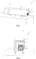
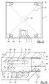
- Fig. 1 shows a starting device 1, which includes a container 2, which is mounted on a trailer 3.
- the trailer serves as a semi-trailer for a towing vehicle.
- Towing vehicle together with trailer 3 and Container 2 act as a land vehicle for transporting one or more underwater hoppers 4, 5 within the container 2.
- FIGS. 1 to 8 show the container 2 with not shown tailgate or rear gates, which serve to close a rear opening 6 of the container 2.
- Fig. 2 shows the starting device according to Fig. 1 in a perspective rear view.
- the underwater hoppers are aligned in the container 2 such that their respective head section is at the rear of the container, while the opposite drive section is at the front of the container.
- the underwater hoppers 4, 5 are received in one or more cages 7, wherein in the illustrated embodiment, the cage 7 is formed as a double cage for receiving two underwater running bodies.
- the cage 7 is formed as a double cage for receiving two underwater running bodies.
- only a double cage 7 is shown within the container 2. However, several single or double cages can be stacked one above the other within a container.
- the cage 7 is formed as a grid frame, so that it drops directly in the case of immersion in water, without the air bubbles could form in up trapped spaces within the cage. That The cage is open on all sides, so that water can flow into the interior of the cage from all sides when the cage is submerged.
- cage 7 is an extendable from the container 2 boom 8, which can be moved out of the rear-side opening 6 of the container 2 horizontally.
- a trolley 9 which is movable along the boom 8, in particular from a region substantially above the center or the center of gravity 7 of the cage together with underwater hoppers 4, 5 to the outermost extendable end of the boom. 8
- the trolley 9 carries a rope by means of which the cage 7 can be raised or lowered.
- the cable is advantageously guided over a arranged on the trolley 9 pulley to a provided in the front region of the container 2 drive means by means of the rope can be extended or retracted.
- the drive device is advantageously arranged in the front region of the container 2 in order to form a counterweight due to its weight, which is required for lifting tons of loads.
- ropes in the broader sense to understand and also includes lifting equipment such as. Slings or chains, especially ball chains, ring chains, roller chains or bridge chains.
- the boom 8 and the trolley 9 are used for loading and unloading of the container 2 and in particular the cage 7 and / or the underwater hoppers 4, 5 in the container 2 and for bringing the cage 7 and the underwater hoppers 4, 5 in a body of water.
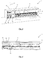
- Fig. 3 shows in the front region of the container 2, ie in the region opposite to the rear opening 6, a control room 10, which is separated by means of a partition wall 11 of the underwater hoppers 4, 5 receiving transport space 12. Within the partition wall 11 is a door 13, which provides a passage from the control room 10 to the transport space 12.
- the partition wall 11 has at least one projection 14, in the region of which the length of the control space 10 is reduced. At the same time, however, the corresponding length of the transport space 12 extends in this area. Therefore, the cage 7 is arranged in the region of the projection 14. In this way, an optimal use of space of the container 2 is given. That It can be housed underwater body maximum length in the container without the control room 10 is unnecessarily restricted, namely that area of the transport space 12 next to the projection 14 the control room 10 is added and thus can be used as cloakroom etc. by the operator of the control room 10 ,
- control room 10 two workstations 15, 16 are provided with screens, keyboards and chairs. These workstations serve as an interface for control systems of the underwater hoppers 4 and 5, which are also housed in the control room 10.
- the control room is connected via a mounted in the container 2 extendable antenna 17 with a mobile or stationary control center in radio communication.
- the antenna 17 therefore serves to exchange data with a higher-level unit.
- the container 2 also has a further extendable antenna 18, which as GPS (Global Positioning System) - detects antenna together with a GPS receiver, the current geographical position of the starting device 1.
- GPS Global Positioning System
- control room 10 climate or. Heaters and the like to create harmless climatic conditions for people and the housed inside the container 2 technical facilities.
- Fig. 4 shows the starting device 1 in a sectional view from above. Good to see the cramped conditions in the control room 10, which are defused by the extension of the control room 10 to the door 13 to some extent. In this area is another door 19 through which the control room 10 can be entered.
- a guide rail 20 on which the boom 8 is guided and held.
- a (not shown) counterweight provided which prevents boom 7 and trolley 9 together with hanging cage 7 with underwater hoppers 4, 5 tilting of the container 2.
- a device room 21 in which further devices, such as radios are housed.
- Fig. 5 shows that this equipment room 21 is accessible via its own door 22.
- Fig. 6 shows the cage 7 during the process of bringing the underwater hoppers 4, 5 into the water.
- the cage 7 is in a relation to the bottom of the container 2 raised state.
- the cage 7 is held by means of a cable 23 which is guided over the trolley 9.
- Both the boom 8 and the trolley 9 are already moved out of the container 2 a piece, so that the cage 7 together with underwater hoppers 4, 5 have emerged from the container 2 a corresponding piece.
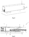
- Fig. 7 shows the boom 8 and the trolley 9 in their fully extended from the container 2 state.
- the cage 7 is in addition to underwater running bodies completely outside the container and indeed already with such a distance from the container 2 that the cage is completely outside, for example, a quay 24 and thus completely over a water surface 25.
- Fig. 8 shows the cage 7 in the immersed state, ie already below the water surface 25.
- the rope 23 has been unwound so far from a winch, that the cage 7 is completely submerged in the water. From this position, the underwater running bodies 4, 5 can be started.
- Fig. 8 shows the underwater hull 5 during the starting process, with its head section is already outside of the cage 7.
- the launching underwater hull 5 generates no significant recoil in or on the cage 7, which could lead to a change in position of the cage 7. Therefore, even in a short time sequence or even substantially simultaneously, the further underwater running body 4 can be started.
- Underwater hull 4 in the present context may be any underwater running body having its own drive.
- these are drones for mine search and / or destruction, to (heavyweight) torpedoes or autonomous underwater vehicles.
- the underwater hoppers 4, 5 are connected during the entire use or at least during a wide portion of the insert via a (not shown) communication line with the control unit 10 provided in the control devices.
- a message line located within the underwater hull 4, 5, a message line, which is wound there on a spool, such as an optical fiber.
- This message line is connected via a corresponding connection to another in a designated outside of the underwater body cartridge 26 (FIG. Fig. 6 ) connected coil connected.
- the cassette is attached to the cage 7 and connected via a robust cable to the control room 10.
- the cartridge 26 remains after the start of the underwater hull 4 on the cage 7. It includes a protective tube that protects the message line from grounding and from waves.
- the protective tube has such a length in order to guide the message line safely into calmer waters nearer to shore.
- the message line is exposed in the water and is further unwound when removing the underwater hull 4 from the located in this underwater hull 4 coil, so that the unwound message line is substantially stationary in the water.
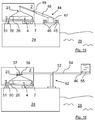
- Fig. 9 shows an alternative embodiment of the invention with a starting device 1 'which is also housed in a container 2.
- the container 2 corresponds to the in the FIGS. 1 to 8 shown container, but in the illustrated embodiment, it has no boom and no trolley. However, the container 2 also contains a control room 10, workstations 15, 16 and antennas 17, 18. Further, in the container in turn a cage 7 is provided with one or more underwater running bodies 4.
- the cage 7 is not in turn spent in the shipment of the underwater hull 4 into the water from the container into the water, but remains in the container 2.
- a slide 27 is provided which connects directly to the cage 7, in particular its lower frame. The slide 27 opens in the water 28th
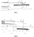
- Fig. 10 shows the underwater hull 4 ready more than half out of the cage 7 out.
- Fig. 11 already shows the completely out of the cage 7 and the container 2 leaked underwater running 4th
- Fig. 12 shows the already largely submerged in the water 28 underwater running 4.
- the cage 7 according to the second embodiment of the FIGS. 9 to 12 can also be designed as a double cage, as in connection with the FIGS. 1 to 8 has been described. Alternatively, however, it may be constructed as a single cage. However, if the cage 7 is formed as a double cage, a double-track formation of the slide 27 is advantageously provided. Alternatively, however, in this case, the slide 27 may be formed in one lane.
- the slide 27 is advantageously supported by supports 30, 31 relative to the ground. Furthermore, preferably, the slide 27 is constructed in segments, so that several slide segments can be placed together to extend the overall length of the slide 27. This is advantageous for guiding the slide 27 into an area of water with sufficient water depth.
- Fig. 13 shows the container 2 in which the cage 7 is stored with the underwater hull 4, and rails 32 which are attached to the container 2.
- a particular embodiment of the cage 7 has a two- or multi-part assembly, so that a base 7 'of a surrounding part 7 "is separable, in particular after transport of the cage is formed such that only the part 7' of the cage available From this position, the underwater hull 4 can be lifted out of the part 7 'of the cage by means of elastic traction cables 33.
- the traction cables 33 are connected to the rails 32.
- the tension cables 33 are tensioned either by moving deflection rollers 34 in or on the rails or by shortening of the pulling cable 33 by means of a winch 35, whereby the underwater running body 4 reaches a dashed position 36.
- the underwater running body 4 is thus in the pretensioned starting position of the catapult.
- Fig. 14 shows the cocked catapult according to Fig. 13 with two elastic ropes 33 each rail 32 and in addition extensions of the rails 32 by means of a telescopic rail 37.
- the telescopic rail 37 has at its end to the rear opening 6, the guide roller 34, and at a further location on the rail 37, a second guide roller 38th In the container 2, corresponding to the deflection rollers 34, 38 fastenings for the traction cables, in particular the winch 35, mounted.
- An attachment device for the cassette 39 is connected to the container 2.
- the underwater hull 4 is connected via the cassette 26 with the mounting device for the cassette 39, which has a trigger system.
- the underwater hull 4 has a holder 40 per pull cable 33.
- the holder 40 is designed such that the pull cable 33 releases as soon as it is opposite to the tensioned tension direction.
- the bracket 40 is not visible due to a spring-driven flap when the pull cable 33 is not connected.
- the elastic tension cable 33 is thus indirectly connected by a deflection roller 41 with the winch 35 via the deflection roller 34 or via the deflection roller 38 with the underwater running body 4 via the holder 40.
- the container 2 has a non-return device 42, 42 'and 42 ".
- the non-return device 42 is designed as a wedge which blocks the tires of the semi-trailer in one direction, namely the direction of return
- the non-return device 42 " is an anchor which connects the carrier system, in particular the container 2, to the substrate.
- the catapult in the tensioned state by a triggering system on the fastening device can be triggered.
- the triggering system is controllable with respect to the connection of the underwater hull 4 with the Bestfest Trentsvoriques the cartridge 39 and has a device for controlled separation, in particular an electrically controllable hook system.
- the catapult 43 thus has a fastening device with a triggering system 39, a tensioning device, in particular by means of the deflection rollers 34, 38 and elastic tension cables 33, on.
- Fig. 15 shows a lifting / crane device 44, which is positioned on the quay 24.
- the range of the lifting / crane device 44 is at least so large that the cage 7 in addition to underwater running body 4 from the container 2 can be lifted and brought into the water 28 without abutting the Kainstrom 24.
- a base of the lifting / crane device 45 is positionable and stabilizable on the quay 24 by means of weighting containers 46, which are in particular filled with water.
- a crane arm 48 on the basis of the lifting / crane device 45 is pivotable.
- the crane arm 48 is through a telescopic device 49 extendable.
- the underwater running body 4 can be connected directly or indirectly via the cage 7 by means of the cable 23.
- the message line of the cassette 26 can be connected to a stationary message line connecting device 51 via an extension of the message line 50, in particular a protective tube-covered message line.
- a stationary message line connecting device 51 By the degrees of freedom of the lifting and crane device 44 of the underwater hull 4 can be brought into the water 28, wherein the cassette 26 in the cage 7 via the extension of the communication line 50 with the stationary communication line connection device 51 is connectable.
- Fig. 16 shows another embodiment of the lifting / crane device 52.
- the stationary base of the lifting / crane device 53 is connected to the quay 24.
- the stationary base of the lifting / crane device 53 consists of at least one, in particular movable, post on which at least one bolt a boom of the lifting / crane device 54 is attached.
- On the boom of the lifting / crane device 54 are two trolleys.
- the trolley for the counterweight 55 is connectable to a weighting container 46.
- the trolley for the underwater hull 56 is connected by means of the cable 23 directly to the underwater hull 4 or indirectly via the cage 7. By means of a winch 57 on the trolley for the underwater hull 56, the cable 23 can be shortened and thus the cage 7 together with underwater hull 4 and cassette 26 can be raised.
- the underwater hull 4 can be brought into the water 28.
- the trolley for the counterweight 55 is timely moved to the trolley for the underwater hull 56, so that a tilting of the lifting / crane device is prevented.
- the message line of the cartridge 26 is connectable to the stationary communication line connecting device 51 by means of the extension of the communication line 50.
- Fig. 17 time a lifting / lowering device 58 in two states.
- the lifting / lowering device 58 is shown in the lowered and loaded state in the water 28.
- the lifting / lowering device 58 is shown in the state when loading.
- the lifting / lowering device 58 consists inter alia of the vertical rail guide 59 which is attached to the quay 24.
- the vertical support rail 60 is mounted, with the height of the lifting / lowering device is adjustable.
- struts 61 the vertical support rail 60 is connected to the horizontal rail guide 62.
- the horizontal support rail 63 is guided.
- the cage 7 is mounted on the container 2 via cage supports 7 "so that the horizontal support rail 63 can be moved under the cage 7.
- the underwater running body 4 is thus in the cage 7 on the horizontally retracted support rail 63 by means of the vertical support rail can be brought into the water 28.
- the extension of the communication line from the cassette to the stationary communication line connection device is not shown for reasons of clarity. Nevertheless, as already described, the message line can be connected to the message line in the connection device.
Applications Claiming Priority (2)
| Application Number | Priority Date | Filing Date | Title |
|---|---|---|---|
| DE102009019556A DE102009019556B4 (de) | 2009-04-30 | 2009-04-30 | Vorrichtung und Verfahren zum Starten eines Unterwasserlaufkörpers |
| PCT/EP2010/055376 WO2010124990A1 (de) | 2009-04-30 | 2010-04-22 | Vorrichtung und verfahren zum starten eines unterwasserlaufkörpers |
Publications (2)
| Publication Number | Publication Date |
|---|---|
| EP2425200A1 EP2425200A1 (de) | 2012-03-07 |
| EP2425200B1 true EP2425200B1 (de) | 2016-05-11 |
Family
ID=42271839
Family Applications (1)
| Application Number | Title | Priority Date | Filing Date |
|---|---|---|---|
| EP10715813.1A Active EP2425200B1 (de) | 2009-04-30 | 2010-04-22 | Vorrichtung und verfahren zum starten eines unterwasserlaufkörpers |
Country Status (7)
| Country | Link |
|---|---|
| US (1) | US8561564B2 (ko) |
| EP (1) | EP2425200B1 (ko) |
| KR (1) | KR101419992B1 (ko) |
| DE (1) | DE102009019556B4 (ko) |
| MY (1) | MY160288A (ko) |
| SG (1) | SG175231A1 (ko) |
| WO (1) | WO2010124990A1 (ko) |
Families Citing this family (12)
| Publication number | Priority date | Publication date | Assignee | Title |
|---|---|---|---|---|
| DE102011000948A1 (de) | 2011-02-25 | 2012-08-30 | Atlas Elektronik Gmbh | Schleppsonaranlage sowie Verfahren zum Durchführen einer Sonarmission mittels einer derartigen Schleppsonaranlage |
| KR101411940B1 (ko) * | 2012-11-09 | 2014-06-26 | 삼성중공업 주식회사 | 수중 스테이션 및 수중 운동체 운용 방법 |
| US9776693B2 (en) * | 2013-03-15 | 2017-10-03 | Hadal, Inc. | Systems and methods for improving buoyancy in underwater vehicles |
| US9127872B1 (en) | 2013-09-25 | 2015-09-08 | Amazon Technologies, Inc. | Mobile storage units for delivery |
| EP2915737B1 (en) * | 2014-03-06 | 2018-05-02 | Alcatel Lucent | Apparatus for lifting and lowering an object |
| CN107074328A (zh) * | 2014-10-07 | 2017-08-18 | 菱重维斯塔斯海上风力有限公司 | 从风轮机发电机平台取出设备部分的装置和方法及填充所述平台上的燃料储罐的方法 |
| DE202016101197U1 (de) * | 2016-03-04 | 2017-06-07 | Fraunhofer-Gesellschaft zur Förderung der angewandten Forschung e.V. | System zum Ausbringen und Bergen eines Unterwasserfahrzeugs |
| US10458778B2 (en) * | 2016-11-17 | 2019-10-29 | Multek Technologies Limited | Inline metrology on air flotation for PCB applications |
| KR102523655B1 (ko) * | 2018-08-01 | 2023-04-18 | 대우조선해양 주식회사 | 잠수함 내 무장탑재 및 이송 장치, 이를 이용한 무장탑재 및 이송 방법 |
| GB2584659B (en) * | 2019-06-07 | 2021-12-22 | Subsea 7 Ltd | Deployment of unmanned underwater vehicles |
| RU2719491C1 (ru) * | 2019-11-05 | 2020-04-20 | Федеральное государственное бюджетное учреждение науки Институт проблем морских технологий Дальневосточного отделения Российской академии наук (ИПМТ ДВО РАН) | Устройство для подводного пуска и приема автономного необитаемого подводного аппарата |
| CN111256535A (zh) * | 2020-03-05 | 2020-06-09 | 西北工业大学 | 一种用于水池的壁挂式变深度水下发射装置 |
Citations (6)
| Publication number | Priority date | Publication date | Assignee | Title |
|---|---|---|---|---|
| DE3209401A1 (de) * | 1982-03-16 | 1983-10-06 | Licentia Gmbh | Unterwasserstart- und ablaufvorrichtung fuer torpedos |
| WO1987005099A1 (en) * | 1986-02-20 | 1987-08-27 | Robert Rydingstam | Torpedo tube |
| US5253605A (en) * | 1992-12-21 | 1993-10-19 | Applied Remote Technology, Inc. | Method and apparatus for deploying and recovering water borne vehicles |
| DE19653329C1 (de) * | 1996-12-20 | 1998-05-14 | Stn Atlas Elektronik Gmbh | Ausbringvorrichtung zum Einsetzen eines Unterwasserlaufkörpers |
| FR2767914A1 (fr) * | 1997-08-28 | 1999-03-05 | France Etat | Conteneur de stockage et de lancement d'une arme du type torpille |
| JP2001199386A (ja) * | 2000-01-20 | 2001-07-24 | Kayaba Ind Co Ltd | 長尺浮遊物の揚収方法および揚収装置 |
Family Cites Families (10)
| Publication number | Priority date | Publication date | Assignee | Title |
|---|---|---|---|---|
| US624472A (en) | 1899-05-09 | Submerged torpedo-tramway | ||
| NL40699C (ko) | 1934-09-21 | |||
| DE1081794B (de) * | 1957-01-15 | 1960-05-12 | Berliner Maschb A G Vormals L | Lufttorpedo, der nach Abwurf ins Trefferfeld mit autarkem Antrieb sein Ziel selbstaendig sucht |
| NL8100610A (nl) * | 1981-02-09 | 1982-09-01 | Rsv Gusto Eng Bv | Drijvende inrichting voor de overslag van lading. |
| US4444087A (en) * | 1982-01-28 | 1984-04-24 | The Boeing Company | Missile container and extraction mechanism |
| US5542333A (en) * | 1983-08-15 | 1996-08-06 | Hughes Missile Systems Company | Undersea vehicle ejection from capsules |
| JPH0480600A (ja) | 1990-07-20 | 1992-03-13 | Ishikawajima Harima Heavy Ind Co Ltd | 発射台 |
| US20090223403A1 (en) | 2006-01-10 | 2009-09-10 | Harding David K | Warhead delivery system |
| US7712429B1 (en) * | 2007-06-28 | 2010-05-11 | United States Of America As Represented By The Secretary Of The Navy | Launch and recovery system for unmanned undersea vehicles |
| DE102009040152A1 (de) * | 2009-05-02 | 2010-11-04 | Atlas Elektronik Gmbh | Verfahren zum Steuern eines Torpedos, Torpedo hierfür sowie Antennensektion eines derartigen Torpedos |
-
2009
- 2009-04-30 DE DE102009019556A patent/DE102009019556B4/de not_active Expired - Fee Related
-
2010
- 2010-04-22 MY MYPI2011005179A patent/MY160288A/en unknown
- 2010-04-22 US US13/265,170 patent/US8561564B2/en active Active
- 2010-04-22 EP EP10715813.1A patent/EP2425200B1/de active Active
- 2010-04-22 KR KR1020117028724A patent/KR101419992B1/ko active IP Right Grant
- 2010-04-22 SG SG2011075132A patent/SG175231A1/en unknown
- 2010-04-22 WO PCT/EP2010/055376 patent/WO2010124990A1/de active Application Filing
Patent Citations (6)
| Publication number | Priority date | Publication date | Assignee | Title |
|---|---|---|---|---|
| DE3209401A1 (de) * | 1982-03-16 | 1983-10-06 | Licentia Gmbh | Unterwasserstart- und ablaufvorrichtung fuer torpedos |
| WO1987005099A1 (en) * | 1986-02-20 | 1987-08-27 | Robert Rydingstam | Torpedo tube |
| US5253605A (en) * | 1992-12-21 | 1993-10-19 | Applied Remote Technology, Inc. | Method and apparatus for deploying and recovering water borne vehicles |
| DE19653329C1 (de) * | 1996-12-20 | 1998-05-14 | Stn Atlas Elektronik Gmbh | Ausbringvorrichtung zum Einsetzen eines Unterwasserlaufkörpers |
| FR2767914A1 (fr) * | 1997-08-28 | 1999-03-05 | France Etat | Conteneur de stockage et de lancement d'une arme du type torpille |
| JP2001199386A (ja) * | 2000-01-20 | 2001-07-24 | Kayaba Ind Co Ltd | 長尺浮遊物の揚収方法および揚収装置 |
Also Published As
| Publication number | Publication date |
|---|---|
| US20130011196A1 (en) | 2013-01-10 |
| KR20120014189A (ko) | 2012-02-16 |
| US8561564B2 (en) | 2013-10-22 |
| SG175231A1 (en) | 2011-11-28 |
| MY160288A (en) | 2017-02-28 |
| KR101419992B1 (ko) | 2014-07-15 |
| DE102009019556B4 (de) | 2012-08-09 |
| WO2010124990A1 (de) | 2010-11-04 |
| EP2425200A1 (de) | 2012-03-07 |
| DE102009019556A1 (de) | 2010-11-04 |
Similar Documents
| Publication | Publication Date | Title |
|---|---|---|
| EP2425200B1 (de) | Vorrichtung und verfahren zum starten eines unterwasserlaufkörpers | |
| EP2739524B1 (de) | System und verfahren zum bergen eines unterwasserfahrzeugs | |
| EP1681234B1 (de) | Hebevorrichtung für Boote | |
| DE2948209A1 (de) | Ortsfeste oder verfahrbare bootshelling | |
| WO2007065495A1 (de) | Gerät zum ausbringen und tracken eines unbemannten unterwasserfahrzeugs | |
| WO2006005705A1 (de) | Offshore-windturbinenhebvorrichtung für wasserfahrzeug | |
| EP0120015A1 (de) | Verladeeinrichtung für gegenüber einem wasserspiegel relativ bewegliche lasten | |
| DE102012112333A1 (de) | Vorrichtung mit einer Aussetz- und Bergungseinrichtung | |
| WO2017149155A1 (de) | System zum ausbringen und bergen eines unterwasserfahrzeugs | |
| DE3334353A1 (de) | Anlage zur lagerung von booten und zum transport der boote zwischen lagerungsort und wasser | |
| DE10045911A1 (de) | Vorrichtung zum Bergen eines Unterwasserfahrzeugs | |
| WO2006053595A1 (de) | Vorrichtung zur offshore-schiffsbeladung oder -entladung | |
| DE3312010A1 (de) | Vorrichtung und verfahren zum be- und entladen von leichtern auf oder von schiffen | |
| DE2811012A1 (de) | Befahrbarer schiffsrumpf fuer frachtschiffe | |
| DE69631371T2 (de) | Führungsschacht für Container-Kräne | |
| DE3608756A1 (de) | Vorrichtung zum slippen eines bootes | |
| DE4431542A1 (de) | Aussetzvorrichtung für Frei-Fall-Rettungsboote in Querschiffsrichtung mit wahlweise nach außenbords ausfahrbarer Ablaufbahn und integriertem Bootsbedienungsmittel zur Wiederaufnahme des Rettungsbootes | |
| DE2352928A1 (de) | Vorrichtung zum transport von wasserfahrzeugen, insbesondere kielbooten | |
| DE20316247U1 (de) | Vorrichtung zum Aussetzen und Aufnehmen eines tauchfähigen Wasserfahrzeuges, Vorrichtung zum Schleppen eines tauchfähigen Wasserfahrzeuges sowie Überwasserfahrzeug mit einer solchen Vorrichtung | |
| WO2000073144A1 (de) | Absetzstation | |
| DE19749204A1 (de) | Transportfahrzeug für Boote | |
| DE2631088A1 (de) | Verladeeinrichtung | |
| WO2018141586A1 (de) | Bootstrailer | |
| DE3707365A1 (de) | Rettungsgeraet zum bergen von personen, insbesondere fuer schiffe | |
| DE2107873A1 (de) | Schragaufzugvomchtung zur Last beförderung |
Legal Events
| Date | Code | Title | Description |
|---|---|---|---|
| PUAI | Public reference made under article 153(3) epc to a published international application that has entered the european phase |
Free format text: ORIGINAL CODE: 0009012 |
|
| 17P | Request for examination filed |
Effective date: 20111110 |
|
| AK | Designated contracting states |
Kind code of ref document: A1 Designated state(s): AT BE BG CH CY CZ DE DK EE ES FI FR GB GR HR HU IE IS IT LI LT LU LV MC MK MT NL NO PL PT RO SE SI SK SM TR |
|
| DAX | Request for extension of the european patent (deleted) | ||
| 17Q | First examination report despatched |
Effective date: 20140227 |
|
| GRAP | Despatch of communication of intention to grant a patent |
Free format text: ORIGINAL CODE: EPIDOSNIGR1 |
|
| INTG | Intention to grant announced |
Effective date: 20150930 |
|
| INTG | Intention to grant announced |
Effective date: 20160302 |
|
| GRAS | Grant fee paid |
Free format text: ORIGINAL CODE: EPIDOSNIGR3 |
|
| GRAA | (expected) grant |
Free format text: ORIGINAL CODE: 0009210 |
|
| AK | Designated contracting states |
Kind code of ref document: B1 Designated state(s): AT BE BG CH CY CZ DE DK EE ES FI FR GB GR HR HU IE IS IT LI LT LU LV MC MK MT NL NO PL PT RO SE SI SK SM TR |
|
| REG | Reference to a national code |
Ref country code: GB Ref legal event code: FG4D Free format text: NOT ENGLISH |
|
| REG | Reference to a national code |
Ref country code: CH Ref legal event code: EP |
|
| REG | Reference to a national code |
Ref country code: AT Ref legal event code: REF Ref document number: 798996 Country of ref document: AT Kind code of ref document: T Effective date: 20160515 |
|
| REG | Reference to a national code |
Ref country code: IE Ref legal event code: FG4D Free format text: LANGUAGE OF EP DOCUMENT: GERMAN |
|
| REG | Reference to a national code |
Ref country code: DE Ref legal event code: R096 Ref document number: 502010011658 Country of ref document: DE |
|
| REG | Reference to a national code |
Ref country code: LT Ref legal event code: MG4D |
|
| REG | Reference to a national code |
Ref country code: NL Ref legal event code: MP Effective date: 20160511 |
|
| PG25 | Lapsed in a contracting state [announced via postgrant information from national office to epo] |
Ref country code: LT Free format text: LAPSE BECAUSE OF FAILURE TO SUBMIT A TRANSLATION OF THE DESCRIPTION OR TO PAY THE FEE WITHIN THE PRESCRIBED TIME-LIMIT Effective date: 20160511 Ref country code: FI Free format text: LAPSE BECAUSE OF FAILURE TO SUBMIT A TRANSLATION OF THE DESCRIPTION OR TO PAY THE FEE WITHIN THE PRESCRIBED TIME-LIMIT Effective date: 20160511 Ref country code: NL Free format text: LAPSE BECAUSE OF FAILURE TO SUBMIT A TRANSLATION OF THE DESCRIPTION OR TO PAY THE FEE WITHIN THE PRESCRIBED TIME-LIMIT Effective date: 20160511 Ref country code: NO Free format text: LAPSE BECAUSE OF FAILURE TO SUBMIT A TRANSLATION OF THE DESCRIPTION OR TO PAY THE FEE WITHIN THE PRESCRIBED TIME-LIMIT Effective date: 20160811 |
|
| PG25 | Lapsed in a contracting state [announced via postgrant information from national office to epo] |
Ref country code: PT Free format text: LAPSE BECAUSE OF FAILURE TO SUBMIT A TRANSLATION OF THE DESCRIPTION OR TO PAY THE FEE WITHIN THE PRESCRIBED TIME-LIMIT Effective date: 20160912 Ref country code: HR Free format text: LAPSE BECAUSE OF FAILURE TO SUBMIT A TRANSLATION OF THE DESCRIPTION OR TO PAY THE FEE WITHIN THE PRESCRIBED TIME-LIMIT Effective date: 20160511 Ref country code: ES Free format text: LAPSE BECAUSE OF FAILURE TO SUBMIT A TRANSLATION OF THE DESCRIPTION OR TO PAY THE FEE WITHIN THE PRESCRIBED TIME-LIMIT Effective date: 20160511 Ref country code: LV Free format text: LAPSE BECAUSE OF FAILURE TO SUBMIT A TRANSLATION OF THE DESCRIPTION OR TO PAY THE FEE WITHIN THE PRESCRIBED TIME-LIMIT Effective date: 20160511 Ref country code: GR Free format text: LAPSE BECAUSE OF FAILURE TO SUBMIT A TRANSLATION OF THE DESCRIPTION OR TO PAY THE FEE WITHIN THE PRESCRIBED TIME-LIMIT Effective date: 20160812 Ref country code: SE Free format text: LAPSE BECAUSE OF FAILURE TO SUBMIT A TRANSLATION OF THE DESCRIPTION OR TO PAY THE FEE WITHIN THE PRESCRIBED TIME-LIMIT Effective date: 20160511 |
|
| PG25 | Lapsed in a contracting state [announced via postgrant information from national office to epo] |
Ref country code: CZ Free format text: LAPSE BECAUSE OF FAILURE TO SUBMIT A TRANSLATION OF THE DESCRIPTION OR TO PAY THE FEE WITHIN THE PRESCRIBED TIME-LIMIT Effective date: 20160511 Ref country code: SK Free format text: LAPSE BECAUSE OF FAILURE TO SUBMIT A TRANSLATION OF THE DESCRIPTION OR TO PAY THE FEE WITHIN THE PRESCRIBED TIME-LIMIT Effective date: 20160511 Ref country code: RO Free format text: LAPSE BECAUSE OF FAILURE TO SUBMIT A TRANSLATION OF THE DESCRIPTION OR TO PAY THE FEE WITHIN THE PRESCRIBED TIME-LIMIT Effective date: 20160511 Ref country code: EE Free format text: LAPSE BECAUSE OF FAILURE TO SUBMIT A TRANSLATION OF THE DESCRIPTION OR TO PAY THE FEE WITHIN THE PRESCRIBED TIME-LIMIT Effective date: 20160511 Ref country code: DK Free format text: LAPSE BECAUSE OF FAILURE TO SUBMIT A TRANSLATION OF THE DESCRIPTION OR TO PAY THE FEE WITHIN THE PRESCRIBED TIME-LIMIT Effective date: 20160511 |
|
| REG | Reference to a national code |
Ref country code: DE Ref legal event code: R097 Ref document number: 502010011658 Country of ref document: DE |
|
| PG25 | Lapsed in a contracting state [announced via postgrant information from national office to epo] |
Ref country code: PL Free format text: LAPSE BECAUSE OF FAILURE TO SUBMIT A TRANSLATION OF THE DESCRIPTION OR TO PAY THE FEE WITHIN THE PRESCRIBED TIME-LIMIT Effective date: 20160511 Ref country code: SM Free format text: LAPSE BECAUSE OF FAILURE TO SUBMIT A TRANSLATION OF THE DESCRIPTION OR TO PAY THE FEE WITHIN THE PRESCRIBED TIME-LIMIT Effective date: 20160511 |
|
| PLBE | No opposition filed within time limit |
Free format text: ORIGINAL CODE: 0009261 |
|
| STAA | Information on the status of an ep patent application or granted ep patent |
Free format text: STATUS: NO OPPOSITION FILED WITHIN TIME LIMIT |
|
| 26N | No opposition filed |
Effective date: 20170214 |
|
| REG | Reference to a national code |
Ref country code: FR Ref legal event code: PLFP Year of fee payment: 8 |
|
| PG25 | Lapsed in a contracting state [announced via postgrant information from national office to epo] |
Ref country code: SI Free format text: LAPSE BECAUSE OF FAILURE TO SUBMIT A TRANSLATION OF THE DESCRIPTION OR TO PAY THE FEE WITHIN THE PRESCRIBED TIME-LIMIT Effective date: 20160511 |
|
| PG25 | Lapsed in a contracting state [announced via postgrant information from national office to epo] |
Ref country code: MC Free format text: LAPSE BECAUSE OF FAILURE TO SUBMIT A TRANSLATION OF THE DESCRIPTION OR TO PAY THE FEE WITHIN THE PRESCRIBED TIME-LIMIT Effective date: 20160511 |
|
| REG | Reference to a national code |
Ref country code: CH Ref legal event code: PL |
|
| REG | Reference to a national code |
Ref country code: IE Ref legal event code: MM4A |
|
| PG25 | Lapsed in a contracting state [announced via postgrant information from national office to epo] |
Ref country code: LI Free format text: LAPSE BECAUSE OF NON-PAYMENT OF DUE FEES Effective date: 20170430 Ref country code: CH Free format text: LAPSE BECAUSE OF NON-PAYMENT OF DUE FEES Effective date: 20170430 Ref country code: LU Free format text: LAPSE BECAUSE OF NON-PAYMENT OF DUE FEES Effective date: 20170422 |
|
| REG | Reference to a national code |
Ref country code: BE Ref legal event code: MM Effective date: 20170430 |
|
| REG | Reference to a national code |
Ref country code: FR Ref legal event code: PLFP Year of fee payment: 9 |
|
| PG25 | Lapsed in a contracting state [announced via postgrant information from national office to epo] |
Ref country code: IE Free format text: LAPSE BECAUSE OF NON-PAYMENT OF DUE FEES Effective date: 20170422 |
|
| PG25 | Lapsed in a contracting state [announced via postgrant information from national office to epo] |
Ref country code: BE Free format text: LAPSE BECAUSE OF NON-PAYMENT OF DUE FEES Effective date: 20170430 |
|
| REG | Reference to a national code |
Ref country code: AT Ref legal event code: MM01 Ref document number: 798996 Country of ref document: AT Kind code of ref document: T Effective date: 20170422 |
|
| PG25 | Lapsed in a contracting state [announced via postgrant information from national office to epo] |
Ref country code: AT Free format text: LAPSE BECAUSE OF NON-PAYMENT OF DUE FEES Effective date: 20170422 |
|
| PG25 | Lapsed in a contracting state [announced via postgrant information from national office to epo] |
Ref country code: MT Free format text: LAPSE BECAUSE OF FAILURE TO SUBMIT A TRANSLATION OF THE DESCRIPTION OR TO PAY THE FEE WITHIN THE PRESCRIBED TIME-LIMIT Effective date: 20160511 |
|
| PG25 | Lapsed in a contracting state [announced via postgrant information from national office to epo] |
Ref country code: HU Free format text: LAPSE BECAUSE OF FAILURE TO SUBMIT A TRANSLATION OF THE DESCRIPTION OR TO PAY THE FEE WITHIN THE PRESCRIBED TIME-LIMIT; INVALID AB INITIO Effective date: 20100422 |
|
| PG25 | Lapsed in a contracting state [announced via postgrant information from national office to epo] |
Ref country code: BG Free format text: LAPSE BECAUSE OF FAILURE TO SUBMIT A TRANSLATION OF THE DESCRIPTION OR TO PAY THE FEE WITHIN THE PRESCRIBED TIME-LIMIT Effective date: 20160511 |
|
| PG25 | Lapsed in a contracting state [announced via postgrant information from national office to epo] |
Ref country code: CY Free format text: LAPSE BECAUSE OF NON-PAYMENT OF DUE FEES Effective date: 20160511 |
|
| PG25 | Lapsed in a contracting state [announced via postgrant information from national office to epo] |
Ref country code: MK Free format text: LAPSE BECAUSE OF FAILURE TO SUBMIT A TRANSLATION OF THE DESCRIPTION OR TO PAY THE FEE WITHIN THE PRESCRIBED TIME-LIMIT Effective date: 20160511 |
|
| PG25 | Lapsed in a contracting state [announced via postgrant information from national office to epo] |
Ref country code: TR Free format text: LAPSE BECAUSE OF FAILURE TO SUBMIT A TRANSLATION OF THE DESCRIPTION OR TO PAY THE FEE WITHIN THE PRESCRIBED TIME-LIMIT Effective date: 20160511 |
|
| PG25 | Lapsed in a contracting state [announced via postgrant information from national office to epo] |
Ref country code: IS Free format text: LAPSE BECAUSE OF FAILURE TO SUBMIT A TRANSLATION OF THE DESCRIPTION OR TO PAY THE FEE WITHIN THE PRESCRIBED TIME-LIMIT Effective date: 20160911 |
|
| P01 | Opt-out of the competence of the unified patent court (upc) registered |
Effective date: 20230530 |
|
| PGFP | Annual fee paid to national office [announced via postgrant information from national office to epo] |
Ref country code: IT Payment date: 20230426 Year of fee payment: 14 Ref country code: FR Payment date: 20230420 Year of fee payment: 14 Ref country code: DE Payment date: 20220620 Year of fee payment: 14 |
|
| PGFP | Annual fee paid to national office [announced via postgrant information from national office to epo] |
Ref country code: GB Payment date: 20230419 Year of fee payment: 14 |