EP2405552B1 - Alimentation inductive adaptative - Google Patents
Alimentation inductive adaptative Download PDFInfo
- Publication number
- EP2405552B1 EP2405552B1 EP11183065.9A EP11183065A EP2405552B1 EP 2405552 B1 EP2405552 B1 EP 2405552B1 EP 11183065 A EP11183065 A EP 11183065A EP 2405552 B1 EP2405552 B1 EP 2405552B1
- Authority
- EP
- European Patent Office
- Prior art keywords
- power supply
- tank circuit
- characteristic
- inductive power
- operating parameter
- Prior art date
- Legal status (The legal status is an assumption and is not a legal conclusion. Google has not performed a legal analysis and makes no representation as to the accuracy of the status listed.)
- Expired - Lifetime
Links
Images


Classifications
-
- H—ELECTRICITY
- H02—GENERATION; CONVERSION OR DISTRIBUTION OF ELECTRIC POWER
- H02J—ELECTRIC POWER NETWORKS; CIRCUIT ARRANGEMENTS OR SYSTEMS FOR SUPPLYING OR DISTRIBUTING ELECTRIC POWER; SYSTEMS FOR STORING ELECTRIC ENERGY
- H02J13/00—Circuit arrangements for providing remote monitoring or remote control of equipment in a power distribution network
- H02J13/13—Circuit arrangements for providing remote monitoring or remote control of equipment in a power distribution network characterised by the transmission of data to equipment in the power network
- H02J13/1331—Circuit arrangements for providing remote monitoring or remote control of equipment in a power distribution network characterised by the transmission of data to equipment in the power network using wireless data transmission
- H02J13/1333—Circuit arrangements for providing remote monitoring or remote control of equipment in a power distribution network characterised by the transmission of data to equipment in the power network using wireless data transmission by means of mobile telephony
-
- A—HUMAN NECESSITIES
- A61—MEDICAL OR VETERINARY SCIENCE; HYGIENE
- A61L—METHODS OR APPARATUS FOR STERILISING MATERIALS OR OBJECTS IN GENERAL; DISINFECTION, STERILISATION OR DEODORISATION OF AIR; CHEMICAL ASPECTS OF BANDAGES, DRESSINGS, ABSORBENT PADS OR SURGICAL ARTICLES; MATERIALS FOR BANDAGES, DRESSINGS, ABSORBENT PADS OR SURGICAL ARTICLES
- A61L2/00—Disinfection or sterilisation of materials or objects, in general; Accessories therefor
- A61L2/02—Disinfection or sterilisation of materials or objects, in general; Accessories therefor using physical processes
- A61L2/08—Radiation
- A61L2/10—Ultraviolet [UV] radiation
-
- H—ELECTRICITY
- H02—GENERATION; CONVERSION OR DISTRIBUTION OF ELECTRIC POWER
- H02J—ELECTRIC POWER NETWORKS; CIRCUIT ARRANGEMENTS OR SYSTEMS FOR SUPPLYING OR DISTRIBUTING ELECTRIC POWER; SYSTEMS FOR STORING ELECTRIC ENERGY
- H02J13/00—Circuit arrangements for providing remote monitoring or remote control of equipment in a power distribution network
- H02J13/13—Circuit arrangements for providing remote monitoring or remote control of equipment in a power distribution network characterised by the transmission of data to equipment in the power network
- H02J13/1331—Circuit arrangements for providing remote monitoring or remote control of equipment in a power distribution network characterised by the transmission of data to equipment in the power network using wireless data transmission
-
- H—ELECTRICITY
- H02—GENERATION; CONVERSION OR DISTRIBUTION OF ELECTRIC POWER
- H02J—ELECTRIC POWER NETWORKS; CIRCUIT ARRANGEMENTS OR SYSTEMS FOR SUPPLYING OR DISTRIBUTING ELECTRIC POWER; SYSTEMS FOR STORING ELECTRIC ENERGY
- H02J13/00—Circuit arrangements for providing remote monitoring or remote control of equipment in a power distribution network
- H02J13/13—Circuit arrangements for providing remote monitoring or remote control of equipment in a power distribution network characterised by the transmission of data to equipment in the power network
- H02J13/1337—Circuit arrangements for providing remote monitoring or remote control of equipment in a power distribution network characterised by the transmission of data to equipment in the power network involving the use of Internet protocols
-
- H—ELECTRICITY
- H02—GENERATION; CONVERSION OR DISTRIBUTION OF ELECTRIC POWER
- H02J—ELECTRIC POWER NETWORKS; CIRCUIT ARRANGEMENTS OR SYSTEMS FOR SUPPLYING OR DISTRIBUTING ELECTRIC POWER; SYSTEMS FOR STORING ELECTRIC ENERGY
- H02J13/00—Circuit arrangements for providing remote monitoring or remote control of equipment in a power distribution network
- H02J13/16—Circuit arrangements for providing remote monitoring or remote control of equipment in a power distribution network the power network being controlled at grid-level, e.g. using aggregators
-
- H—ELECTRICITY
- H02—GENERATION; CONVERSION OR DISTRIBUTION OF ELECTRIC POWER
- H02J—ELECTRIC POWER NETWORKS; CIRCUIT ARRANGEMENTS OR SYSTEMS FOR SUPPLYING OR DISTRIBUTING ELECTRIC POWER; SYSTEMS FOR STORING ELECTRIC ENERGY
- H02J50/00—Circuit arrangements or systems for wireless supply or distribution of electric power
- H02J50/10—Circuit arrangements or systems for wireless supply or distribution of electric power using inductive coupling
- H02J50/12—Circuit arrangements or systems for wireless supply or distribution of electric power using inductive coupling of the resonant type
-
- H—ELECTRICITY
- H02—GENERATION; CONVERSION OR DISTRIBUTION OF ELECTRIC POWER
- H02J—ELECTRIC POWER NETWORKS; CIRCUIT ARRANGEMENTS OR SYSTEMS FOR SUPPLYING OR DISTRIBUTING ELECTRIC POWER; SYSTEMS FOR STORING ELECTRIC ENERGY
- H02J7/00—Circuit arrangements for charging or discharging batteries or for supplying loads from batteries
- H02J7/70—Circuit arrangements for charging or discharging batteries or for supplying loads from batteries characterised by the mechanical construction
-
- H—ELECTRICITY
- H02—GENERATION; CONVERSION OR DISTRIBUTION OF ELECTRIC POWER
- H02M—APPARATUS FOR CONVERSION BETWEEN AC AND AC, BETWEEN AC AND DC, OR BETWEEN DC AND DC, AND FOR USE WITH MAINS OR SIMILAR POWER SUPPLY SYSTEMS; CONVERSION OF DC OR AC INPUT POWER INTO SURGE OUTPUT POWER; CONTROL OR REGULATION THEREOF
- H02M3/00—Conversion of DC power input into DC power output
- H02M3/22—Conversion of DC power input into DC power output with intermediate conversion into AC
- H02M3/24—Conversion of DC power input into DC power output with intermediate conversion into AC by static converters
- H02M3/28—Conversion of DC power input into DC power output with intermediate conversion into AC by static converters using discharge tubes with control electrode or semiconductor devices with control electrode to produce the intermediate AC
- H02M3/325—Conversion of DC power input into DC power output with intermediate conversion into AC by static converters using discharge tubes with control electrode or semiconductor devices with control electrode to produce the intermediate AC using devices of a triode or a transistor type requiring continuous application of a control signal
- H02M3/335—Conversion of DC power input into DC power output with intermediate conversion into AC by static converters using discharge tubes with control electrode or semiconductor devices with control electrode to produce the intermediate AC using devices of a triode or a transistor type requiring continuous application of a control signal using semiconductor devices only
- H02M3/33507—Conversion of DC power input into DC power output with intermediate conversion into AC by static converters using discharge tubes with control electrode or semiconductor devices with control electrode to produce the intermediate AC using devices of a triode or a transistor type requiring continuous application of a control signal using semiconductor devices only with automatic control of the output voltage or current, e.g. flyback converters
- H02M3/33523—Conversion of DC power input into DC power output with intermediate conversion into AC by static converters using discharge tubes with control electrode or semiconductor devices with control electrode to produce the intermediate AC using devices of a triode or a transistor type requiring continuous application of a control signal using semiconductor devices only with automatic control of the output voltage or current, e.g. flyback converters with galvanic isolation between input and output of both the power stage and the feedback loop
-
- H—ELECTRICITY
- H02—GENERATION; CONVERSION OR DISTRIBUTION OF ELECTRIC POWER
- H02M—APPARATUS FOR CONVERSION BETWEEN AC AND AC, BETWEEN AC AND DC, OR BETWEEN DC AND DC, AND FOR USE WITH MAINS OR SIMILAR POWER SUPPLY SYSTEMS; CONVERSION OF DC OR AC INPUT POWER INTO SURGE OUTPUT POWER; CONTROL OR REGULATION THEREOF
- H02M3/00—Conversion of DC power input into DC power output
- H02M3/22—Conversion of DC power input into DC power output with intermediate conversion into AC
- H02M3/24—Conversion of DC power input into DC power output with intermediate conversion into AC by static converters
- H02M3/28—Conversion of DC power input into DC power output with intermediate conversion into AC by static converters using discharge tubes with control electrode or semiconductor devices with control electrode to produce the intermediate AC
- H02M3/325—Conversion of DC power input into DC power output with intermediate conversion into AC by static converters using discharge tubes with control electrode or semiconductor devices with control electrode to produce the intermediate AC using devices of a triode or a transistor type requiring continuous application of a control signal
- H02M3/335—Conversion of DC power input into DC power output with intermediate conversion into AC by static converters using discharge tubes with control electrode or semiconductor devices with control electrode to produce the intermediate AC using devices of a triode or a transistor type requiring continuous application of a control signal using semiconductor devices only
- H02M3/33569—Conversion of DC power input into DC power output with intermediate conversion into AC by static converters using discharge tubes with control electrode or semiconductor devices with control electrode to produce the intermediate AC using devices of a triode or a transistor type requiring continuous application of a control signal using semiconductor devices only having several active switching elements
- H02M3/33576—Conversion of DC power input into DC power output with intermediate conversion into AC by static converters using discharge tubes with control electrode or semiconductor devices with control electrode to produce the intermediate AC using devices of a triode or a transistor type requiring continuous application of a control signal using semiconductor devices only having several active switching elements having at least one active switching element at the secondary side of an isolation transformer
-
- H—ELECTRICITY
- H02—GENERATION; CONVERSION OR DISTRIBUTION OF ELECTRIC POWER
- H02M—APPARATUS FOR CONVERSION BETWEEN AC AND AC, BETWEEN AC AND DC, OR BETWEEN DC AND DC, AND FOR USE WITH MAINS OR SIMILAR POWER SUPPLY SYSTEMS; CONVERSION OF DC OR AC INPUT POWER INTO SURGE OUTPUT POWER; CONTROL OR REGULATION THEREOF
- H02M7/00—Conversion of AC power input into DC power output; Conversion of DC power input into AC power output
- H02M7/42—Conversion of DC power input into AC power output without possibility of reversal
- H02M7/44—Conversion of DC power input into AC power output without possibility of reversal by static converters
- H02M7/48—Conversion of DC power input into AC power output without possibility of reversal by static converters using discharge tubes with control electrode or semiconductor devices with control electrode
- H02M7/53—Conversion of DC power input into AC power output without possibility of reversal by static converters using discharge tubes with control electrode or semiconductor devices with control electrode using devices of a triode or transistor type requiring continuous application of a control signal
- H02M7/537—Conversion of DC power input into AC power output without possibility of reversal by static converters using discharge tubes with control electrode or semiconductor devices with control electrode using devices of a triode or transistor type requiring continuous application of a control signal using semiconductor devices only, e.g. single switched pulse inverters
- H02M7/538—Conversion of DC power input into AC power output without possibility of reversal by static converters using discharge tubes with control electrode or semiconductor devices with control electrode using devices of a triode or transistor type requiring continuous application of a control signal using semiconductor devices only, e.g. single switched pulse inverters in a push-pull configuration
- H02M7/53803—Conversion of DC power input into AC power output without possibility of reversal by static converters using discharge tubes with control electrode or semiconductor devices with control electrode using devices of a triode or transistor type requiring continuous application of a control signal using semiconductor devices only, e.g. single switched pulse inverters in a push-pull configuration with automatic control of output voltage or current
-
- H—ELECTRICITY
- H05—ELECTRIC TECHNIQUES NOT OTHERWISE PROVIDED FOR
- H05B—ELECTRIC HEATING; ELECTRIC LIGHT SOURCES NOT OTHERWISE PROVIDED FOR; CIRCUIT ARRANGEMENTS FOR ELECTRIC LIGHT SOURCES, IN GENERAL
- H05B41/00—Circuit arrangements or apparatus for igniting or operating discharge lamps
- H05B41/14—Circuit arrangements
- H05B41/36—Controlling
-
- H—ELECTRICITY
- H05—ELECTRIC TECHNIQUES NOT OTHERWISE PROVIDED FOR
- H05B—ELECTRIC HEATING; ELECTRIC LIGHT SOURCES NOT OTHERWISE PROVIDED FOR; CIRCUIT ARRANGEMENTS FOR ELECTRIC LIGHT SOURCES, IN GENERAL
- H05B47/00—Circuit arrangements for operating light sources in general, i.e. where the type of light source is not relevant
- H05B47/20—Responsive to malfunctions or to light source life; for protection
-
- H—ELECTRICITY
- H02—GENERATION; CONVERSION OR DISTRIBUTION OF ELECTRIC POWER
- H02J—ELECTRIC POWER NETWORKS; CIRCUIT ARRANGEMENTS OR SYSTEMS FOR SUPPLYING OR DISTRIBUTING ELECTRIC POWER; SYSTEMS FOR STORING ELECTRIC ENERGY
- H02J2105/00—Networks for supplying or distributing electric power characterised by their spatial reach or by the load
- H02J2105/30—Networks for supplying or distributing electric power characterised by their spatial reach or by the load the load networks being external to vehicles, i.e. exchanging power with vehicles
- H02J2105/33—Networks for supplying or distributing electric power characterised by their spatial reach or by the load the load networks being external to vehicles, i.e. exchanging power with vehicles exchanging power with road vehicles
-
- H—ELECTRICITY
- H02—GENERATION; CONVERSION OR DISTRIBUTION OF ELECTRIC POWER
- H02J—ELECTRIC POWER NETWORKS; CIRCUIT ARRANGEMENTS OR SYSTEMS FOR SUPPLYING OR DISTRIBUTING ELECTRIC POWER; SYSTEMS FOR STORING ELECTRIC ENERGY
- H02J2105/00—Networks for supplying or distributing electric power characterised by their spatial reach or by the load
- H02J2105/40—Networks for supplying or distributing electric power characterised by their spatial reach or by the load characterised by the loads connecting to the networks or being supplied by the networks
- H02J2105/44—Portable electronic devices
-
- H—ELECTRICITY
- H02—GENERATION; CONVERSION OR DISTRIBUTION OF ELECTRIC POWER
- H02M—APPARATUS FOR CONVERSION BETWEEN AC AND AC, BETWEEN AC AND DC, OR BETWEEN DC AND DC, AND FOR USE WITH MAINS OR SIMILAR POWER SUPPLY SYSTEMS; CONVERSION OF DC OR AC INPUT POWER INTO SURGE OUTPUT POWER; CONTROL OR REGULATION THEREOF
- H02M3/00—Conversion of DC power input into DC power output
- H02M3/01—Resonant DC/DC converters
- H02M3/015—Resonant DC/DC converters with means for adaptation of resonance frequency, e.g. by modification of capacitance or inductance of resonance circuit
-
- H—ELECTRICITY
- H02—GENERATION; CONVERSION OR DISTRIBUTION OF ELECTRIC POWER
- H02M—APPARATUS FOR CONVERSION BETWEEN AC AND AC, BETWEEN AC AND DC, OR BETWEEN DC AND DC, AND FOR USE WITH MAINS OR SIMILAR POWER SUPPLY SYSTEMS; CONVERSION OF DC OR AC INPUT POWER INTO SURGE OUTPUT POWER; CONTROL OR REGULATION THEREOF
- H02M3/00—Conversion of DC power input into DC power output
- H02M3/22—Conversion of DC power input into DC power output with intermediate conversion into AC
- H02M3/24—Conversion of DC power input into DC power output with intermediate conversion into AC by static converters
- H02M3/28—Conversion of DC power input into DC power output with intermediate conversion into AC by static converters using discharge tubes with control electrode or semiconductor devices with control electrode to produce the intermediate AC
- H02M3/325—Conversion of DC power input into DC power output with intermediate conversion into AC by static converters using discharge tubes with control electrode or semiconductor devices with control electrode to produce the intermediate AC using devices of a triode or a transistor type requiring continuous application of a control signal
- H02M3/335—Conversion of DC power input into DC power output with intermediate conversion into AC by static converters using discharge tubes with control electrode or semiconductor devices with control electrode to produce the intermediate AC using devices of a triode or a transistor type requiring continuous application of a control signal using semiconductor devices only
- H02M3/33569—Conversion of DC power input into DC power output with intermediate conversion into AC by static converters using discharge tubes with control electrode or semiconductor devices with control electrode to produce the intermediate AC using devices of a triode or a transistor type requiring continuous application of a control signal using semiconductor devices only having several active switching elements
- H02M3/33571—Half-bridge at primary side of an isolation transformer
-
- H—ELECTRICITY
- H02—GENERATION; CONVERSION OR DISTRIBUTION OF ELECTRIC POWER
- H02M—APPARATUS FOR CONVERSION BETWEEN AC AND AC, BETWEEN AC AND DC, OR BETWEEN DC AND DC, AND FOR USE WITH MAINS OR SIMILAR POWER SUPPLY SYSTEMS; CONVERSION OF DC OR AC INPUT POWER INTO SURGE OUTPUT POWER; CONTROL OR REGULATION THEREOF
- H02M7/00—Conversion of AC power input into DC power output; Conversion of DC power input into AC power output
- H02M7/42—Conversion of DC power input into AC power output without possibility of reversal
- H02M7/44—Conversion of DC power input into AC power output without possibility of reversal by static converters
- H02M7/48—Conversion of DC power input into AC power output without possibility of reversal by static converters using discharge tubes with control electrode or semiconductor devices with control electrode
- H02M7/4815—Resonant converters
- H02M7/4818—Resonant converters with means for adaptation of resonance frequency, e.g. by modification of capacitance or inductance of resonance circuits
-
- Y—GENERAL TAGGING OF NEW TECHNOLOGICAL DEVELOPMENTS; GENERAL TAGGING OF CROSS-SECTIONAL TECHNOLOGIES SPANNING OVER SEVERAL SECTIONS OF THE IPC; TECHNICAL SUBJECTS COVERED BY FORMER USPC CROSS-REFERENCE ART COLLECTIONS [XRACs] AND DIGESTS
- Y02—TECHNOLOGIES OR APPLICATIONS FOR MITIGATION OR ADAPTATION AGAINST CLIMATE CHANGE
- Y02B—CLIMATE CHANGE MITIGATION TECHNOLOGIES RELATED TO BUILDINGS, e.g. HOUSING, HOUSE APPLIANCES OR RELATED END-USER APPLICATIONS
- Y02B70/00—Technologies for an efficient end-user side electric power management and consumption
- Y02B70/10—Technologies improving the efficiency by using switched-mode power supplies [SMPS], i.e. efficient power electronics conversion e.g. power factor correction or reduction of losses in power supplies or efficient standby modes
-
- Y—GENERAL TAGGING OF NEW TECHNOLOGICAL DEVELOPMENTS; GENERAL TAGGING OF CROSS-SECTIONAL TECHNOLOGIES SPANNING OVER SEVERAL SECTIONS OF THE IPC; TECHNICAL SUBJECTS COVERED BY FORMER USPC CROSS-REFERENCE ART COLLECTIONS [XRACs] AND DIGESTS
- Y02—TECHNOLOGIES OR APPLICATIONS FOR MITIGATION OR ADAPTATION AGAINST CLIMATE CHANGE
- Y02B—CLIMATE CHANGE MITIGATION TECHNOLOGIES RELATED TO BUILDINGS, e.g. HOUSING, HOUSE APPLIANCES OR RELATED END-USER APPLICATIONS
- Y02B70/00—Technologies for an efficient end-user side electric power management and consumption
- Y02B70/30—Systems integrating technologies related to power network operation and communication or information technologies for improving the carbon footprint of the management of residential or tertiary loads, i.e. smart grids as climate change mitigation technology in the buildings sector, including also the last stages of power distribution and the control, monitoring or operating management systems at local level
-
- Y—GENERAL TAGGING OF NEW TECHNOLOGICAL DEVELOPMENTS; GENERAL TAGGING OF CROSS-SECTIONAL TECHNOLOGIES SPANNING OVER SEVERAL SECTIONS OF THE IPC; TECHNICAL SUBJECTS COVERED BY FORMER USPC CROSS-REFERENCE ART COLLECTIONS [XRACs] AND DIGESTS
- Y04—INFORMATION OR COMMUNICATION TECHNOLOGIES HAVING AN IMPACT ON OTHER TECHNOLOGY AREAS
- Y04S—SYSTEMS INTEGRATING TECHNOLOGIES RELATED TO POWER NETWORK OPERATION, COMMUNICATION OR INFORMATION TECHNOLOGIES FOR IMPROVING THE ELECTRICAL POWER GENERATION, TRANSMISSION, DISTRIBUTION, MANAGEMENT OR USAGE, i.e. SMART GRIDS
- Y04S20/00—Management or operation of end-user stationary applications or the last stages of power distribution; Controlling, monitoring or operating thereof
- Y04S20/20—End-user application control systems
- Y04S20/242—Home appliances
- Y04S20/246—Home appliances the system involving the remote operation of lamps or lighting equipment
Definitions
- This invention relates generally to contactless power supplies, and more specifically to inductively coupled contactless power supplies.
- CEETS Contactless energy transmission systems
- CEETS are composed of power supplies and remote devices.
- the remote devices could be chargeable, such as batteries, micro-capacitors, or any other chargeable energy source.
- CEETS could directly power the devices.
- CEETS uses magnetic induction to transfer energy. Energy from a primary winding in the power supply is transferred inductively to a secondary winding in the chargeable device. Because the secondary winding is physically spaced from the primary winding, the inductive coupling occurs through the air.
- CEETS dedicated to one type of device.
- a CEETS for a rechargeable toothbrush is designed only for recharging a toothbrush, while a CEETS for a rechargeable telephone works only with a specific type of telephone. While this solution allows the CEET to operate effectively with one particular device, it fails to be sufficiently flexible to allow the power supply to operate with different rechargeable devices.
- Prior art includes WO 02/37641 which discloses a charging device for a portable device; and, more particularly, to a noncontact charging device for charging a rechargeable battery of a portable device by the induction coupling between a charger and the rechargeable battery.
- an inductive power supply for supplying power to a remote device according to claim 3.
- a contactless power supply inductively couples by way of a tank circuit to a device.
- the power supply has a controller for dynamically adjusting the resonant frequency of the tank circuit.
- the tank circuit could have either a variable capacitor or a variable inductor, or both.
- the power supply also may have an inverter.
- a drive circuit connected to the inverter controls the frequency of the inverter and the duty cycle of the inverter.
- a controller with an attached memory directs the operation of the inverter by way of the drive circuit.
- the inverter may also be connected to a DC power source. The controller could then change the rail voltage of the DC power source.
- the contactless power supply can energize a variety of different devices.
- the power supply can even energize several different devices at the same time. This ability to power a multitude of different devices overcomes many of the limitations previously associated with CEETS. Further, because the power supply can energize a variety of different devices, a central single source for supply power to a variety of small electronic devices is possible.
- a sensor may also coupled to the tank circuit. It would monitor various operational characteristics of the tank circuit, such as the phase of the current within the tank circuit. These operation characteristics are indicative of the total load energized by the power supply. When the operational characteristics indicate that the power supply is not efficiently supplying power to the load, the controller causes the power supply to seek an improved configuration.
- the process of seeking an improved configuration may include one or more of the following steps.
- the power supply could automatically attempt to compensate by changing the frequency of the inverter and the duty cycle of the inverter. If this sufficiently correct the efficiency of the power supply, the controller causes the tank circuit to change its resonant frequency.
- the resonant frequency of a tank circuit is in fact a range centered about a frequency.
- the tank circuit will resonate at frequencies which are approximately the resonant frequency.
- the adaptive power supply described herein reconfigures the tank circuit to have a substantially different resonant frequency.
- the tank circuit may consist of either a variable inductor or a variable capacitor or both.
- the controller would then change the inductance of the variable inductor or the capacitance of the variable capacitor, or both, thus causing the tank circuit to have a different resonant frequency.
- the controller may also establish a new rail voltage for the DC power source. It also sets a new inverter frequency and a new duty cycle for the inverter. The adaptive power supply then operates with the new configuration.
- the power supply will once again attempt to rectify the problem by changing the frequency of the inverter and the duty cycle of the inverter. If the problem is still not corrected, then the power supply will repeat the process of reconfiguring the tank circuit, setting a new inverter frequency and setting a new duty cycle.
- This power supply continually searches for the most efficient settings to deliver power to the devices. However, if none of the various settings delivers power efficiently to the devices, then the power supply will select the most efficient of the previous configurations and operate the power supply with those settings.
- the power supply efficiently powers a variety of loads. Further, because the power supply is contactless, a user does not need to have a multitude of different power supplies or connectors.
- the present invention provides an adaptive inductive ballast circuit in which the inductance and/or the capacitance of the power supply circuit is variable to provide a broad range of adaptability, thereby permitting the ballast circuit to power a variety of inductively powered devices with widely differing load characteristics.
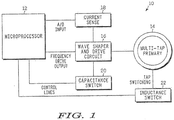
- FIG. 1 A block diagram showing the general construction of an adaptive inductive ballast 10 in accordance with one embodiment of the present invention is shown in FIG. 1 .
- the adaptive inductive ballast 10 generally includes a microprocessor 12 that controls operation of the circuit, a multi-tap primary 14 for generating a magnetic field, a wave shaper and drive subcircuit 16 that generates the signal applied to the primary 14, a current sense subcircuit 18 that monitors the signal applied to the primary 14 and provides corresponding feedback to the microprocessor 12, a capacitance switch 20 for adjusting the capacitance values in the wave shaper and drive subcircuit 16, and an inductance switch 22 for adjusting the inductance of the multi-tap primary 14.
- the microprocessor is a conventional microprocessor widely available from a variety of suppliers.
- the capacitance switch 20 generally includes two banks of capacitors and a plurality of switches, such as transistors, that are selectively actuatable by the microprocessor 12 to control the values of the two capacitor banks.
- the capacitors in each bank can be arranged in series or parallel depending on the desired range and distribution of possible capacitance values.
- the first bank of capacitors replace capacitor 271 of the pre-existing resonance-seeking ballast shown in the above referenced application.
- the second back of capacitors replace capacitor 272 of the pre-existing resonance-seeking ballast shown in the above referenced patent application.
- the capacitance switch 20 makes capacitors 271 and 272 from the pre-existing resonance-seeking ballast into variable capacitors, the values of which are controlled by the microprocessor 12.
- the described capacitance switch 20 can be replaced by other circuitry capable of providing variable capacitance.
- the inductance switch 22 generally includes a multi-tap primary 14 and a plurality of switches, such as transistors, that are selectively actuatable by the microprocessor 12 to control the values of the inductance of the primary 14.
- the multi-tap primary 14 replaces primary 270 of the pre-existing resonance-seeking ballast shown in the attached patent application.
- the inductance switch 22 makes primary 270 from the pre-existing resonance-seeking ballast into a variable inductance coil by varying the number of turns in the primary 14, the value of which is controlled by the microprocessor 12.
- the described inductance switch 22 can be replaced by other circuitry capable of providing variable inductance.
- the microprocessor 12 is programmed to receive input from the current sense subcircuit 18, which is indicative of the current applied to the primary 14.
- the microprocessor 12 is programmed to separately adjust the capacitance switch 20 and the inductance switch 22 to cycle through the range of capacitance values and inductance values available to the circuit.
- the microprocessor 12 continues to monitor the input from the current sense circuit 18 while adjusting the capacitance and inductance values to determine which values provide optimum current to the primary 14.
- the microprocessor 12 then locks the adaptive ballast into the optimum settings.
- a ballast feedback circuit is connected at point A and a control circuit is connected at point B.
- Oscillator 144 provides half bridge inverter 148 with an alternating signal by way of drive 146.
- Half bridge inverter powers tank circuit 150.
- Current sensing circuit 218 provides feedback to oscillator 144.
- the feedback circuit, control circuit, oscillator, half bridge inverter, drive and current sensing circuit 218 as well as other supporting circuitry is more fully described in the above referenced patent application.
- a phase delay could be inserted at E and can be controlled as a delay line or even DSP (Digital Signal Processing) could be used to delay this signal. This delay can be used to throttle the phase and control secondary amplitude.
- switched capacitance can adjust the resonant frequency based on the adjustable primary inductance. Simple transistors can be used to switch in and out capacitance. The capacitance is changed when the primary inductor changes as to match load.
- primary inductance can be switched to adjust the power required by the secondary circuit With that load information, the control processor can adjust the inductance as needed to provide the power required.
- the inductance can be switched using transistors and multiple taps from the primary inductor controlled by the microprocessor.
- the illustrated system waits until it determines that a load is present before applying power to the primary 14. This will save power and may be done by providing each inductively powered device with a magnet that actuates a reed switch adjacent to the primary. Alternatively, a user-actuated switch (not shown) may be provided so that the user can engage the power supply when an inductively powered device is present. As another alternative, the inductively powered device may be configured to mechanically actuate a switch when it is placed into located by the primary to signal its presence. As a further alternative, the switching mechanism can be eliminated and the ballast circuit can provide power to the primary 14 regardless of the presence of a load.
- the circuit adjusts its frequency to optimize the current applied to the primary.
- the microprocessor locks the ballast circuit into the operating frequency and then begins to cycle through the range of inductance values available through the multi-tap primary. After each change in inductance value, the microprocessor unlocks the operating frequency and permits the ballast circuit to seek resonance, settling at a frequency that provides optimal current to the primary. The microprocessor continues cycling through the available inductance values until it has determined which value provides optimal current to the primary. In one embodiment, a progressive scanning process is used to determine the appropriate inductance value.
- the microprocessor can step through each inductance value to determine the corresponding current, and after stepping through each value, return to the inductance value that provided the greatest current to the primary.
- the microprocessor locks the circuit at the determined inductance value and begins to cycle through the capacitance values.
- the microprocessor uses a progressive scanning technique to determine the capacitance that provides the primary with the greatest current. The scanning process may progress upwardly from the lowest capacitance value or downwardly from the highest capacitance value, as described above in connection with the scanning process for the inductance value.
- the microprocessor can step through each capacitance value to determine the corresponding current, and after stepping through each value, return to the capacitance value that provided the greatest current to the primary.
- the frequency of the ballast circuit is not permitted to vary once the appropriate inductance value has been determined.
- the microprocessor can, alternatively, be programmed to permit the ballast circuit to seek resonance after each change in capacitance value.
- the microprocessor may be programmed to provide adjustment of only the capacitance value or only the inductance value of the power supply circuit.
- the multi-tap primary can be replaced by a conventional single-tap primary and the inductance switch can be eliminated.
- the capacitor bank can be replaced by a single set of capacitors and the capacitance switch can be eliminated.
- the microprocessor can be programmed to adjust the capacitance before adjusting the inductance.
- the adaptive inductive ballast 10 may include phase delay circuitry (not shown) that permits the ballast 10 to throttle the phase and control secondary amplitude.
- the phase delay circuitry may include a delay line or a Digital Signal Processor (DSP) that is connected to the wave shaper and drive circuit 16 following the operational amplifier 210.
- DSP Digital Signal Processor
- an additional embodiment for an adaptive contactless energy transmission system is shown in the block diagram of FIG. 4 .
- the adaptive contactless energy transmission system is comprised of adaptive inductive power supply 305 and remote device 307.
- power source 310 is a DC power source providing DC (direct current) power to inverter 312.
- Inverter 312 converts the DC power to AC (alternating current) power.
- Inverter 312 acts as an AC power source supplying the AC power to tank circuit 314.
- Tank circuit 314 is inductively coupled to secondary winding 316 of remote device 307.
- Secondary winding 316 of remote device 307 has no core.
- Line 322 indicates an air gap between remote device 307 and adaptive inductive power supply 305.
- Remote device 307 has a load 320.
- Load 320 could include a rechargeable device, such as a micro-capacitor or a rechargeable battery.
- load 320 could be a lamp, radio or any other electrical device adapted to receive power from adaptive inductive power supply 305 whenever remote device 307 is placed in proximity of adaptive inductive power supply 305.
- Circuit sensor 324 is coupled to the tank circuit 314 and inverter 312. Circuit sensor 324 is also coupled to controller 326. Circuit sensor 324 provides information regarding the operational parameters of adaptive inductive power supply 305. For example, circuit sensor 324 could be a current sensor used to provide controller 326 information regarding the phase, frequency and amplitude of the current in tank circuit 314.
- Controller 326 could be any one of a multitude of commonly available microcontrollers programmed to perform the functions hereinafter described, such as the Intel 8051 or the Motorola 6811, or any of the many variants of those microcontrollers. Controller 326 could have a ROM (read only memory) and RAM (random access memory) on the chip. Controller 326 could have a series of analog and digital outputs for controlling the various functions within the adaptive inductive power supply.
- Controller 326 is connected to memory 327. Controller 326 is also coupled to drive circuit 328.
- Drive circuit 328 regulates the operation of inverter 312, such as the frequency and timing of inverter 312.
- Drive circuit 328 could be constructed in a number of different manners.
- driver circuit 328 could be constructed of discrete components such as transistors, resistors and capacitors; it could be a discrete integrated circuit designed to drive inverters; or it could be a functional component of controller 326 if controller 326 were a microcontroller.
- Controller 326 is also coupled to power source 310. Controller 326 can manipulate the rail voltage of power source 310. As is well known, by altering the rail voltage of power source 310, the amplitude of the output of inverter 312 is also altered.
- controller 326 is coupled to variable inductor 330 and variable capacitor 332 of tank circuit 314.
- Controller 326 could be a microcontroller, such as an 8051-type microcontroller.
- controller 326 could be a microprocessor with additional supporting circuitry.
- Controller 326 can modify the inductance of variable inductor 330 or the capacitance of variable capacitor 332. This could be done, e.g., by switching in or out additional capacitor or inductors or by changing the physical characteristics of variable inductor 330 or variable capacitor 332. By modifying the inductance of variable inductor 330 and the capacitance of variable capacitor 332, the resonant frequency of tank circuit 314 can be changed.
- tank circuit 314 may have a first resonant frequency and a second resonant frequency.
- Tank circuit 314 could also have several resonant frequencies.
- the term "resonant frequency” refers to a band of frequencies within which tank circuit 314 will resonate. As is well known, a tank circuit will have a resonant frequency, but will continue to resonate within a range of frequencies.
- Variable inductor 330 could be a thyristor controlled variable inductor, a compressible variable inductor, parallel laminated core variable inductor, a series of inductors and switches capable of placing select fixed inductors into tank circuit 314, or any other controllable variable inductor.
- Variable capacitor 332 could be a switched capacitor array, a series of fixed capacitors and switches capable of placing select fixed capacitors into tank circuit 314, or any other controllable variable capacitor.
- Tank circuit 314 also includes primary winding 334.
- Primary winding 334 and variable inductor 330 are shown separate. Alternatively, primary winding 334 and variable inductor 330 could be combined into a single element.
- Tank circuit 314 is shown as a series resonant tank circuit. A parallel resonant tank circuit could also be used.
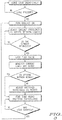
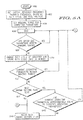
- FIGs. 5A and 5B show a flow chart showing the operation of adaptive inductive power supply 305 of adaptive contactless energy transmission system shown in FIG. 4 .
- controller 326 When turned on (step 400), controller 326 initializes the resonant frequency of tank circuit 314 by setting the inductance of variable inductor 330 and the capacitance variable capacitor 332 so that tank circuit 314 operates at a pre-selected initial resonant frequency. Step 402. Controller 326 initializes drive circuit 328 to operate at a pre-selected frequency with a pre-selected phase offset. Controller 326 initializes power source 310 to operate at a predetermined rail voltage. Step 402.
- adaptive inductive power supply 305 when adaptive inductive power supply 305 is initially energized, adaptive inductive power supply 305 might be initialized to supply power at a very low level. Alternatively, adaptive inductive power supply 305 might be initialized to supply power at a more moderate level to accommodate some common remote devices.
- the operating parameters for the power supply are various measures of current and voltage throughout the system.
- the peak to peak inverter voltage, the RMS current flowing through the primary winding, and the phase offset of the current flowing through the primary winding are all operating parameters.
- the operating range could include a range of the phase offset between the inverter voltage and the voltage current, a range for the current amplitude, and a range for the inverter output voltage.
- an operating range could be an inverter voltage from 5 Volts to 5.3 volts, with a current phase offset of no more than 20 degrees, and a current amplitude of between 1 ⁇ 2 and 1 amp.
- the nominal range is the acceptable range of possible values for the operating parameters. If an operating parameter are not within the nominal range, then the power supply is not operating efficiently.
- Controller 326 continually monitors the operating parameters of adaptive inductive power supply 305. If the operating parameters fall within the nominal range, then the circuit continues to idle. Step 408.
- controller 326 reconfigures adaptive inductive power supply 305.
- adaptive inductive power supply 305 had an initially low power setting, adaptive inductive power supply 305 would thus sense the presence of the remote device, and automatically increase power to a more moderate level.
- reconfiguration of adaptive inductive power supply 305 could be triggered by one operating parameter falling outside of the nominal range, or reconfiguration of adaptive inductive power supply 305 could be triggered by a combination of operating parameters falling outside of the nominal range. It is satisfactory to monitor only the phase of the current flowing through the primary winding. However, various enhancements where other operating parameters are measured and weighted together could be readily conceived.
- controller 326 causes drive circuit 328 to alter the duty cycle of inverter 312. Step 410.
- the duty cycle of inverter 312 is altered, and the altered duty cycle is stored in memory 327.
- Step 412 If the operating parameters are still outside of the nominal range, then a 'best known setting' flag is checked. Step 414. The 'best known setting' flag is discussed below.
- controller 326 determines whether the inverter frequency can be adjusted and still maintain resonance within tank circuit 314. Step 418. Controller 326 first finds the maximum and minimum resonant frequency of tank circuit 314.
- the maximum and minimum resonant frequency of tank circuit 314 for any particular configuration of variable inductor 330 and variable capacitor 332 could be stored in memory 327.
- the maximum and minimum resonant frequency of tank circuit 314 could be calculated from the inductance of primary winding 334, the inductance of variable inductor 330, and the capacitance of variable capacitor 332. Controller 326 then compares the maximum and minimum resonant frequency of tank circuit 314 with the current operating frequency of inverter 312.
- controller 326 causes drive circuit 328 to adjust the inverter frequency and stores the new inverter frequency in memory 327. Step 420. The circuit returns to the idle state. Step 406. If the inverter frequency cannot be adjusted within the resonant frequency of the current configuration of tank circuit 314, then controller 326 determines whether the configuration of tank circuit 314 can be modified. Step 422.
- controller 326 stores the current frequency, duty cycle, rail voltage, tank circuit configuration, and operating parameters in memory 327. Step 424. It then adjust the tank circuit resonant frequency. Step 426. Adjustment of the tank circuit resonant frequency is accomplished by changing the inductance of variable inductor 330 and the capacitance of variable capacitor 332.
- Step 428 Since the resonant frequency of tank circuit 314 has been altered, a new nominal range for the operating parameters is calculated or loaded from memory 327. Step 430. The power supply then returns to idle. Step 406.
- controller 326 searches for the best prior configuration. Step 432. Controller 326 compares the operating parameters previously stored and selects the best configuration.
- controller 326 retrieves various settings of adaptive inductive power supply 305 from memory for that configuration. Step 433. Controller 326 then sets the configuration of tank circuit 314 by setting the inductance of adjustable inductor 30 and capacitance of adjustable capacitor 32. Step 434. Controller 326 then sets the frequency of inverter 312. Step 436. Controller 326 then sets the duty cycle of inverter 312. Step 438. Controller 326 sets the rail voltage of power source 310. Step 440.
- Controller 326 then stores the expected operating parameters in memory 327. Step 442. Alternatively, controller 326 could set a pointer to the expecting operating parameters in memory 327. Controller 326 then sets the 'best known setting' flag. Step 444. The power supply then returns to the idle state. Step 406. The 'best known setting' flag is an indication to controller 326 that the current settings being used by adaptive inductive power supply 305 are the best available.
- the system checks if the operating parameters are approximately equal to the expected operating parameters.
- controller 326 checks whether the current operating parameters are approximately the same as the expected operating parameters. Step 446. If so, then further adjustments to power supply will not result in any improved performance, and therefore the system merely returns to the idle state. Step 406.
- Step 448 The process of reconfiguring adaptive inductive power supply 305 continues. Step 422.
- Adaptive inductive power supply 305 automatically adjusts to different devices with different loads, and continually determines and optimal operating configuration for the power supply.
- adaptive inductive power supply 305 more than a single device can be simultaneously powered by adaptive inductive power supply 305.
- controller 326 continually adjusts the operating parameters of adaptive inductive power supply 305 to maintain efficiency. This allows for one single power supply to provide power to a multitude of different devices.
- the devices need not be located immediately adjacent adaptive inductive power supply 305. That can be spaced at different distances away from adaptive inductive power supply 305. For example, it is possible to construct a power supply whereby sealed lights are stacked near adaptive inductive power supply 305 and each light will be illuminated even though the distance from adaptive inductive power supply 305 is different for each light.
Landscapes
- Engineering & Computer Science (AREA)
- Power Engineering (AREA)
- Health & Medical Sciences (AREA)
- Life Sciences & Earth Sciences (AREA)
- Epidemiology (AREA)
- Animal Behavior & Ethology (AREA)
- General Health & Medical Sciences (AREA)
- Public Health (AREA)
- Veterinary Medicine (AREA)
- Computer Networks & Wireless Communication (AREA)
- Inverter Devices (AREA)
- Hydrology & Water Resources (AREA)
- Environmental & Geological Engineering (AREA)
- Water Supply & Treatment (AREA)
- Chemical & Material Sciences (AREA)
- Organic Chemistry (AREA)
- Dc-Dc Converters (AREA)
- Toxicology (AREA)
- Control Of Electrical Variables (AREA)
- Current-Collector Devices For Electrically Propelled Vehicles (AREA)
Claims (6)
- Procédé de fonctionnement d'une alimentation en énergie inductive pour un dispositif à distance (307), le procédé comprenant les étapes consistant à :appliquer de l'énergie à un circuit oscillant (314) dans l'alimentation en énergie inductive, l'énergie appliquée au circuit oscillant ayant une fréquence de fonctionnement, une tension de ligne, un rapport cyclique et le circuit oscillant (314) ayant une fréquence de résonance ajustable ;établir un couplage inductif entre l'alimentation en énergie inductive et le dispositif à distance (307) avec une fréquence de fonctionnement initiale, la tension de ligne, le rapport cyclique et la fréquence de résonance ajustable du circuit oscillant (314) et entrer dans un état de repos ;surveiller de manière répétée au moins un paramètre de fonctionnement de l'alimentation en énergie inductive après avoir établi le couplage inductif et, en fonction de cette surveillance :a) quand le au moins un paramètre de fonctionnement de l'alimentation en énergie inductive est dans une plage nominale, retourner à l'état de repos,b) quand le au moins un paramètre de fonctionnement de l'alimentation en énergie inductive ne se trouve pas dans une plage nominale, reconfigurer l'alimentation en énergie inductive en :- ajustant au moins une première caractéristique de l'alimentation en énergie, la première caractéristique étant l'un parmi ladite fréquence de fonctionnement, ladite tension de ligne, ou ledit rapport cyclique ;- ajustant une seconde caractéristique de l'alimentation en énergie, la seconde caractéristique étant la fréquence de résonance du circuit oscillant (314) ;- si, après l'ajustement de la seconde caractéristique, le au moins un paramètre de fonctionnement se trouve dans la plage nominale, mémoriser et utiliser les réglages définis par la au moins une première caractéristique, la seconde caractéristique et le au moins un paramètre de fonctionnement ; et- si, après l'ajustement de la seconde caractéristique, le au moins un paramètre de fonctionnement ne se trouve pas dans la plage nominale, trouver et utiliser le meilleur réglage antérieur mémorisé.
- Procédé selon la revendication 1, dans lequel ladite étape de surveillance répétée d'au moins un paramètre de fonctionnement de l'alimentation en énergie inductive est en outre définie comme une détection d'au moins un paramètre de fonctionnement du circuit oscillant.
- Alimentation en énergie inductive pour alimenter en énergie un dispositif à distance (307) comprenant :un circuit oscillant (314) ayant un élément primaire pour transférer de l'énergie sans fil au dispositif à distance (307) par un couplage inductif, ledit circuit oscillant (314) ayant une fréquence de résonance ajustable ;un onduleur (148, 312) pour appliquer de l'énergie audit circuit oscillant (314), ledit onduleur (148, 312) appliquant de l'énergie audit circuit oscillant (314) à une fréquence de fonctionnement et à un rapport cyclique ;une source d'alimentation DC (310) couplée audit onduleur (148, 312) pour fournir une énergie DC audit onduleur (148, 312), ladite source d'alimentation DC (310) ayant une tension de ligne ;un circuit d'attaque (328) couplé audit onduleur (148, 312), ledit circuit d'attaque (328) imposant ladite fréquence de fonctionnement et ledit rapport cyclique ; etun dispositif de commande (326) pour reconfigurer de manière dynamique l'alimentation en énergie inductive, ledit dispositif de commande étant configuré pour :établir un couplage inductif entre l'alimentation en énergie inductive et le dispositif à distance (307) avec une fréquence de fonctionnement initiale, une tension de ligne, un rapport cyclique et une fréquence de résonance ajustable circuit oscillant (314) et entrer dans un état de repos ;surveiller de manière répétée au moins un paramètre de fonctionnement de l'alimentation en énergie inductive après avoir établi le couplage inductif et, en fonction de cette surveillance :a) quand le au moins un paramètre de fonctionnement de l'alimentation en énergie inductive est dans une plage nominale, retourner à l'état de repos,b) quand le au moins un paramètre de fonctionnement de l'alimentation en énergie inductive ne se trouve pas dans une plage nominale, reconfigurer l'alimentation en énergie inductive en :- ajustant au moins une première caractéristique de l'alimentation en énergie, la première caractéristique étant l'un parmi ladite fréquence de fonctionnement, ladite tension de ligne, ou ledit rapport cyclique ;- ajustant une seconde caractéristique de l'alimentation en énergie, la seconde caractéristique étant la fréquence de résonance du circuit oscillant (314) ;- si, après l'ajustement de la seconde caractéristique, le au moins un paramètre de fonctionnement se trouve dans la plage nominale, mémoriser et utiliser les réglages définis par la au moins une première caractéristique, la seconde caractéristique et le au moins un paramètre de fonctionnement ; et- si, après l'ajustement de la seconde caractéristique, le au moins un paramètre de fonctionnement ne se trouve pas dans la plage nominale, trouver et utiliser le meilleur réglage antérieur mémorisé.
- Alimentation en énergie inductive selon la revendication 3, dans laquelle ladite alimentation en énergie inductive inclut au moins l'un parmi un condensateur variable (332) et une inductance variable (330), dans laquelle ledit dispositif de commande (326) est configuré pour faire varier au moins l'un parmi le condensateur variable (332) et l'inductance variable (330) pour ajuster ladite fréquence de résonance.
- Alimentation en énergie inductive selon la revendication 3, incluant en outre un capteur de circuit (324) couplé audit circuit oscillant (314) et audit dispositif de commande (326), ledit capteur de circuit (324) fournissant audit dispositif de commande (326) une entrée indiquant au moins un paramètre de fonctionnement dudit circuit oscillant (314).
- Alimentation en énergie inductive ou procédé, selon le cas, selon la revendication 2 ou 5, dans laquelle ledit au moins un paramètre de fonctionnement du circuit oscillant (314) est un courant.
Applications Claiming Priority (4)
| Application Number | Priority Date | Filing Date | Title |
|---|---|---|---|
| US44479403P | 2003-02-04 | 2003-02-04 | |
| US10/689,499 US7212414B2 (en) | 1999-06-21 | 2003-10-20 | Adaptive inductive power supply |
| EP04704453A EP1590877A1 (fr) | 2003-02-04 | 2004-01-22 | Alimentation par induction adaptative |
| PCT/US2004/001758 WO2004073150A1 (fr) | 2003-02-04 | 2004-01-22 | Alimentation par induction adaptative |
Related Parent Applications (2)
| Application Number | Title | Priority Date | Filing Date |
|---|---|---|---|
| EP04704453.2 Division | 2004-01-22 | ||
| EP04704453A Division EP1590877A1 (fr) | 2003-02-04 | 2004-01-22 | Alimentation par induction adaptative |
Publications (3)
| Publication Number | Publication Date |
|---|---|
| EP2405552A2 EP2405552A2 (fr) | 2012-01-11 |
| EP2405552A3 EP2405552A3 (fr) | 2015-05-06 |
| EP2405552B1 true EP2405552B1 (fr) | 2019-10-09 |
Family
ID=32871931
Family Applications (4)
| Application Number | Title | Priority Date | Filing Date |
|---|---|---|---|
| EP11183065.9A Expired - Lifetime EP2405552B1 (fr) | 2003-02-04 | 2004-01-22 | Alimentation inductive adaptative |
| EP20110183064 Withdrawn EP2405564A3 (fr) | 2003-02-04 | 2004-01-22 | Alimentation inductive adaptative |
| EP11183066.7A Withdrawn EP2405553A3 (fr) | 2003-02-04 | 2004-01-22 | Alimentation inductive adaptative |
| EP04704453A Ceased EP1590877A1 (fr) | 2003-02-04 | 2004-01-22 | Alimentation par induction adaptative |
Family Applications After (3)
| Application Number | Title | Priority Date | Filing Date |
|---|---|---|---|
| EP20110183064 Withdrawn EP2405564A3 (fr) | 2003-02-04 | 2004-01-22 | Alimentation inductive adaptative |
| EP11183066.7A Withdrawn EP2405553A3 (fr) | 2003-02-04 | 2004-01-22 | Alimentation inductive adaptative |
| EP04704453A Ceased EP1590877A1 (fr) | 2003-02-04 | 2004-01-22 | Alimentation par induction adaptative |
Country Status (8)
| Country | Link |
|---|---|
| US (8) | US7212414B2 (fr) |
| EP (4) | EP2405552B1 (fr) |
| JP (2) | JP2006518179A (fr) |
| KR (5) | KR101239041B1 (fr) |
| CN (2) | CN1768467B (fr) |
| MY (3) | MY144505A (fr) |
| TW (2) | TWI367615B (fr) |
| WO (1) | WO2004073150A1 (fr) |
Families Citing this family (398)
| Publication number | Priority date | Publication date | Assignee | Title |
|---|---|---|---|---|
| US7522878B2 (en) * | 1999-06-21 | 2009-04-21 | Access Business Group International Llc | Adaptive inductive power supply with communication |
| US7212414B2 (en) | 1999-06-21 | 2007-05-01 | Access Business Group International, Llc | Adaptive inductive power supply |
| US7065658B1 (en) | 2001-05-18 | 2006-06-20 | Palm, Incorporated | Method and apparatus for synchronizing and recharging a connector-less portable computer system |
| JP4614961B2 (ja) * | 2003-05-23 | 2011-01-19 | オークランド ユニサービシズ リミテッド | 誘導結合電力伝達システムを制御する方法および装置 |
| CN1813396B (zh) * | 2003-05-23 | 2010-04-28 | 奥克兰联合服务有限公司 | 谐振变换器及其方法以及感耦电能传送系统 |
| JP4036813B2 (ja) * | 2003-09-30 | 2008-01-23 | シャープ株式会社 | 非接触電力供給システム |
| GB2414120B (en) | 2004-05-11 | 2008-04-02 | Splashpower Ltd | Controlling inductive power transfer systems |
| US7605496B2 (en) | 2004-05-11 | 2009-10-20 | Access Business Group International Llc | Controlling inductive power transfer systems |
| KR20040072581A (ko) * | 2004-07-29 | 2004-08-18 | (주)제이씨 프로텍 | 전자기파 증폭중계기 및 이를 이용한 무선전력변환장치 |
| US7462951B1 (en) * | 2004-08-11 | 2008-12-09 | Access Business Group International Llc | Portable inductive power station |
| NZ535390A (en) | 2004-09-16 | 2007-10-26 | Auckland Uniservices Ltd | Inductively powered mobile sensor system |
| JP4318044B2 (ja) | 2005-03-03 | 2009-08-19 | ソニー株式会社 | 電力供給システム、電力供給装置および方法、受電装置および方法、記録媒体、並びにプログラム |
| DE102005022352A1 (de) * | 2005-05-13 | 2006-11-23 | BSH Bosch und Siemens Hausgeräte GmbH | Energieübertragungsvorrichtung |
| US7825543B2 (en) * | 2005-07-12 | 2010-11-02 | Massachusetts Institute Of Technology | Wireless energy transfer |
| KR101118710B1 (ko) | 2005-07-12 | 2012-03-13 | 메사추세츠 인스티튜트 오브 테크놀로지 | 무선 비-방사성 에너지 전달 |
| US7352567B2 (en) * | 2005-08-09 | 2008-04-01 | Apple Inc. | Methods and apparatuses for docking a portable electronic device that has a planar like configuration and that operates in multiple orientations |
| US7382636B2 (en) * | 2005-10-14 | 2008-06-03 | Access Business Group International Llc | System and method for powering a load |
| US20070109819A1 (en) * | 2005-11-17 | 2007-05-17 | Powell George L | Modulated tuned L/C transmitter circuits |
| WO2007069293A1 (fr) * | 2005-12-12 | 2007-06-21 | Matsushita Electric Industrial Co., Ltd. | Systeme de batterie rechargeable sans contact, dispositif de charge et bloc-batterie |
| JP4813171B2 (ja) * | 2005-12-16 | 2011-11-09 | 株式会社豊田自動織機 | ステータの製造方法及び製造装置 |
| US8447234B2 (en) * | 2006-01-18 | 2013-05-21 | Qualcomm Incorporated | Method and system for powering an electronic device via a wireless link |
| US9130602B2 (en) | 2006-01-18 | 2015-09-08 | Qualcomm Incorporated | Method and apparatus for delivering energy to an electrical or electronic device via a wireless link |
| US7952322B2 (en) * | 2006-01-31 | 2011-05-31 | Mojo Mobility, Inc. | Inductive power source and charging system |
| US11201500B2 (en) | 2006-01-31 | 2021-12-14 | Mojo Mobility, Inc. | Efficiencies and flexibilities in inductive (wireless) charging |
| US8169185B2 (en) * | 2006-01-31 | 2012-05-01 | Mojo Mobility, Inc. | System and method for inductive charging of portable devices |
| US7989986B2 (en) * | 2006-03-23 | 2011-08-02 | Access Business Group International Llc | Inductive power supply with device identification |
| US7355150B2 (en) | 2006-03-23 | 2008-04-08 | Access Business Group International Llc | Food preparation system with inductive power |
| US11245287B2 (en) | 2006-03-23 | 2022-02-08 | Philips Ip Ventures B.V. | Inductive power supply with device identification |
| US7948208B2 (en) | 2006-06-01 | 2011-05-24 | Mojo Mobility, Inc. | Power source, charging system, and inductive receiver for mobile devices |
| US11329511B2 (en) | 2006-06-01 | 2022-05-10 | Mojo Mobility Inc. | Power source, charging system, and inductive receiver for mobile devices |
| JP4855150B2 (ja) * | 2006-06-09 | 2012-01-18 | 株式会社トプコン | 眼底観察装置、眼科画像処理装置及び眼科画像処理プログラム |
| US9022293B2 (en) | 2006-08-31 | 2015-05-05 | Semiconductor Energy Laboratory Co., Ltd. | Semiconductor device and power receiving device |
| US8013473B2 (en) * | 2006-09-01 | 2011-09-06 | Atmel Corporation | Detector based combination regulator |
| US9129741B2 (en) | 2006-09-14 | 2015-09-08 | Qualcomm Incorporated | Method and apparatus for wireless power transmission |
| TWI339471B (en) * | 2006-12-27 | 2011-03-21 | Ind Tech Res Inst | Non-contact power supply having built-in coupling detection device and coupling detection method thereof |
| DK176584B1 (da) * | 2007-01-04 | 2008-10-06 | Gn Netcom As | Hovedsæt med genopladeligt batteri, baseenhed indrettet til at oplade et genopladeligt batteri samt en kommunikationsenhed |
| RU2498541C2 (ru) * | 2007-01-08 | 2013-11-10 | Эксесс Бизнесс Груп Интернешнл Ллс | Цепь индуктивного питания газоразрядной лампы |
| US7821208B2 (en) * | 2007-01-08 | 2010-10-26 | Access Business Group International Llc | Inductively-powered gas discharge lamp circuit |
| MX2009008011A (es) * | 2007-01-29 | 2010-02-18 | Powermat Ltd | Acoplamiento de energia sin clavija y metodo para controlar la transferenca de la energia atraves de un acoplamiento inductivo. |
| US9774086B2 (en) * | 2007-03-02 | 2017-09-26 | Qualcomm Incorporated | Wireless power apparatus and methods |
| CN102106054A (zh) * | 2007-03-22 | 2011-06-22 | 鲍尔马特有限公司 | 信号传递系统 |
| US9421388B2 (en) | 2007-06-01 | 2016-08-23 | Witricity Corporation | Power generation for implantable devices |
| US8805530B2 (en) * | 2007-06-01 | 2014-08-12 | Witricity Corporation | Power generation for implantable devices |
| US9124120B2 (en) | 2007-06-11 | 2015-09-01 | Qualcomm Incorporated | Wireless power system and proximity effects |
| KR100814097B1 (ko) * | 2007-06-25 | 2008-03-14 | 일신하이텍 주식회사 | 비접촉 급전장치를 포함하는 엘시디 에이징 시스템 |
| CN101842962B (zh) * | 2007-08-09 | 2014-10-08 | 高通股份有限公司 | 增加谐振器的q因数 |
| US10069341B2 (en) | 2007-08-21 | 2018-09-04 | Auckland Uniservices Limited | Inductively powered mobile sensor system |
| GB0716679D0 (en) * | 2007-08-28 | 2007-10-03 | Fells J | Inductive power supply |
| EP2188863A1 (fr) | 2007-09-13 | 2010-05-26 | QUALCOMM Incorporated | Maximisation du rendement énergétique de résonateurs magnétiques de puissance sans fil |
| EP2201641A1 (fr) * | 2007-09-17 | 2010-06-30 | Qualcomm Incorporated | Emetteurs et récepteurs pour un transfert d'énergie sans fil |
| AU2008309020B2 (en) * | 2007-09-28 | 2012-12-20 | Access Business Group International Llc | Multiphase inductive power supply system |
| EP2208279A4 (fr) * | 2007-10-11 | 2016-11-30 | Qualcomm Inc | Transfert de puissance sans fil utilisant des systèmes magnéto-mécaniques |
| US8729734B2 (en) * | 2007-11-16 | 2014-05-20 | Qualcomm Incorporated | Wireless power bridge |
| US9472971B2 (en) | 2007-12-21 | 2016-10-18 | Cynetic Designs Ltd. | Wireless inductive charging of weapon system energy source |
| CN103259344B (zh) | 2007-12-21 | 2016-08-10 | 捷通国际有限公司 | 用于感应功率传输的电路 |
| EP2232669B1 (fr) * | 2008-01-07 | 2019-12-04 | Philips IP Ventures B.V. | Alimentation électrique inductrice avec commande de cycle de marche |
| RU2010133056A (ru) * | 2008-01-07 | 2012-02-20 | Эксесс Бизнес Груп Интернейшнл Ллс (Us) | Беспроводной силовой адаптер для компьютера |
| US9128687B2 (en) * | 2008-01-10 | 2015-09-08 | Qualcomm Incorporated | Wireless desktop IT environment |
| NZ565234A (en) * | 2008-01-18 | 2010-11-26 | Telemetry Res Ltd | Selectable resonant frequency transcutaneous energy transfer system |
| KR101594286B1 (ko) | 2008-02-22 | 2016-02-15 | 액세스 비지니스 그룹 인터내셔날 엘엘씨 | 유도성 커플링을 위한 자기 위치 설정 시스템 |
| US8344552B2 (en) | 2008-02-27 | 2013-01-01 | Qualcomm Incorporated | Antennas and their coupling characteristics for wireless power transfer via magnetic coupling |
| US8855554B2 (en) * | 2008-03-05 | 2014-10-07 | Qualcomm Incorporated | Packaging and details of a wireless power device |
| US8421267B2 (en) * | 2008-03-10 | 2013-04-16 | Qualcomm, Incorporated | Packaging and details of a wireless power device |
| WO2009114671A1 (fr) * | 2008-03-13 | 2009-09-17 | Access Business Group International Llc | Système d’alimentation de puissance inductive à pluralité de primaires de bobine |
| KR20100130215A (ko) | 2008-03-17 | 2010-12-10 | 파우워매트 엘티디. | 유도송전장치 |
| US8629576B2 (en) * | 2008-03-28 | 2014-01-14 | Qualcomm Incorporated | Tuning and gain control in electro-magnetic power systems |
| CN102017361B (zh) | 2008-04-21 | 2016-02-24 | 高通股份有限公司 | 无线功率传送系统及方法 |
| US20110050164A1 (en) | 2008-05-07 | 2011-03-03 | Afshin Partovi | System and methods for inductive charging, and improvements and uses thereof |
| US8878393B2 (en) | 2008-05-13 | 2014-11-04 | Qualcomm Incorporated | Wireless power transfer for vehicles |
| US8629650B2 (en) * | 2008-05-13 | 2014-01-14 | Qualcomm Incorporated | Wireless power transfer using multiple transmit antennas |
| WO2009140506A1 (fr) * | 2008-05-14 | 2009-11-19 | Massachusetts Institute Of Technology | Transfert d'énergie sans fil, comprenant une amélioration vis-à-vis d'une interférence |
| US20090299918A1 (en) * | 2008-05-28 | 2009-12-03 | Nigelpower, Llc | Wireless delivery of power to a mobile powered device |
| ES2326780B2 (es) * | 2008-05-29 | 2010-06-16 | Fundacion Circe - Centro De Investigacion De Recursos Y Consumos Energeticos | Metodo automatico de control de un sistema de transferencia de potencia con acoplamiento inductivo en alta frecuencia. |
| CA2726552A1 (fr) * | 2008-06-02 | 2009-12-10 | Powermat Ltd. | Prises de courant montees sur des appareils electriques |
| CN102047550B (zh) * | 2008-06-03 | 2014-04-30 | 株式会社村田制作所 | 电容器电路和电力变换电路 |
| US11979201B2 (en) | 2008-07-02 | 2024-05-07 | Powermat Technologies Ltd. | System and method for coded communication signals regulating inductive power transmissions |
| US8981598B2 (en) | 2008-07-02 | 2015-03-17 | Powermat Technologies Ltd. | Energy efficient inductive power transmission system and method |
| US8188619B2 (en) | 2008-07-02 | 2012-05-29 | Powermat Technologies Ltd | Non resonant inductive power transmission system and method |
| AU2009269574A1 (en) * | 2008-07-08 | 2010-01-14 | Powermat Technologies Ltd. | Display device |
| US7893564B2 (en) * | 2008-08-05 | 2011-02-22 | Broadcom Corporation | Phased array wireless resonant power delivery system |
| USD640976S1 (en) | 2008-08-28 | 2011-07-05 | Hewlett-Packard Development Company, L.P. | Support structure and/or cradle for a mobile computing device |
| JP4911148B2 (ja) * | 2008-09-02 | 2012-04-04 | ソニー株式会社 | 非接触給電装置 |
| US8527688B2 (en) * | 2008-09-26 | 2013-09-03 | Palm, Inc. | Extending device functionality amongst inductively linked devices |
| US8712324B2 (en) | 2008-09-26 | 2014-04-29 | Qualcomm Incorporated | Inductive signal transfer system for computing devices |
| US20110106954A1 (en) * | 2008-09-26 | 2011-05-05 | Manjirnath Chatterjee | System and method for inductively pairing devices to share data or resources |
| US8385822B2 (en) * | 2008-09-26 | 2013-02-26 | Hewlett-Packard Development Company, L.P. | Orientation and presence detection for use in configuring operations of computing devices in docked environments |
| US8850045B2 (en) | 2008-09-26 | 2014-09-30 | Qualcomm Incorporated | System and method for linking and sharing resources amongst devices |
| US8401469B2 (en) * | 2008-09-26 | 2013-03-19 | Hewlett-Packard Development Company, L.P. | Shield for use with a computing device that receives an inductive signal transmission |
| US8688037B2 (en) * | 2008-09-26 | 2014-04-01 | Hewlett-Packard Development Company, L.P. | Magnetic latching mechanism for use in mating a mobile computing device to an accessory device |
| US8234509B2 (en) * | 2008-09-26 | 2012-07-31 | Hewlett-Packard Development Company, L.P. | Portable power supply device for mobile computing devices |
| US8868939B2 (en) | 2008-09-26 | 2014-10-21 | Qualcomm Incorporated | Portable power supply device with outlet connector |
| US8587153B2 (en) | 2008-09-27 | 2013-11-19 | Witricity Corporation | Wireless energy transfer using high Q resonators for lighting applications |
| US8692412B2 (en) | 2008-09-27 | 2014-04-08 | Witricity Corporation | Temperature compensation in a wireless transfer system |
| US9106203B2 (en) | 2008-09-27 | 2015-08-11 | Witricity Corporation | Secure wireless energy transfer in medical applications |
| US8963488B2 (en) | 2008-09-27 | 2015-02-24 | Witricity Corporation | Position insensitive wireless charging |
| US8587155B2 (en) | 2008-09-27 | 2013-11-19 | Witricity Corporation | Wireless energy transfer using repeater resonators |
| US8957549B2 (en) | 2008-09-27 | 2015-02-17 | Witricity Corporation | Tunable wireless energy transfer for in-vehicle applications |
| US8461720B2 (en) | 2008-09-27 | 2013-06-11 | Witricity Corporation | Wireless energy transfer using conducting surfaces to shape fields and reduce loss |
| US8304935B2 (en) | 2008-09-27 | 2012-11-06 | Witricity Corporation | Wireless energy transfer using field shaping to reduce loss |
| US8928276B2 (en) | 2008-09-27 | 2015-01-06 | Witricity Corporation | Integrated repeaters for cell phone applications |
| US9601270B2 (en) | 2008-09-27 | 2017-03-21 | Witricity Corporation | Low AC resistance conductor designs |
| US8933594B2 (en) | 2008-09-27 | 2015-01-13 | Witricity Corporation | Wireless energy transfer for vehicles |
| US8901779B2 (en) | 2008-09-27 | 2014-12-02 | Witricity Corporation | Wireless energy transfer with resonator arrays for medical applications |
| US8686598B2 (en) | 2008-09-27 | 2014-04-01 | Witricity Corporation | Wireless energy transfer for supplying power and heat to a device |
| US8922066B2 (en) | 2008-09-27 | 2014-12-30 | Witricity Corporation | Wireless energy transfer with multi resonator arrays for vehicle applications |
| US9744858B2 (en) | 2008-09-27 | 2017-08-29 | Witricity Corporation | System for wireless energy distribution in a vehicle |
| US8692410B2 (en) | 2008-09-27 | 2014-04-08 | Witricity Corporation | Wireless energy transfer with frequency hopping |
| US8772973B2 (en) | 2008-09-27 | 2014-07-08 | Witricity Corporation | Integrated resonator-shield structures |
| US9396867B2 (en) | 2008-09-27 | 2016-07-19 | Witricity Corporation | Integrated resonator-shield structures |
| WO2010036980A1 (fr) | 2008-09-27 | 2010-04-01 | Witricity Corporation | Systèmes de transfert d'énergie sans fil |
| US9184595B2 (en) | 2008-09-27 | 2015-11-10 | Witricity Corporation | Wireless energy transfer in lossy environments |
| US8400017B2 (en) | 2008-09-27 | 2013-03-19 | Witricity Corporation | Wireless energy transfer for computer peripheral applications |
| US8441154B2 (en) | 2008-09-27 | 2013-05-14 | Witricity Corporation | Multi-resonator wireless energy transfer for exterior lighting |
| US8907531B2 (en) | 2008-09-27 | 2014-12-09 | Witricity Corporation | Wireless energy transfer with variable size resonators for medical applications |
| US8461722B2 (en) | 2008-09-27 | 2013-06-11 | Witricity Corporation | Wireless energy transfer using conducting surfaces to shape field and improve K |
| US9246336B2 (en) | 2008-09-27 | 2016-01-26 | Witricity Corporation | Resonator optimizations for wireless energy transfer |
| US9318922B2 (en) | 2008-09-27 | 2016-04-19 | Witricity Corporation | Mechanically removable wireless power vehicle seat assembly |
| US8487480B1 (en) | 2008-09-27 | 2013-07-16 | Witricity Corporation | Wireless energy transfer resonator kit |
| US9515494B2 (en) | 2008-09-27 | 2016-12-06 | Witricity Corporation | Wireless power system including impedance matching network |
| US8946938B2 (en) | 2008-09-27 | 2015-02-03 | Witricity Corporation | Safety systems for wireless energy transfer in vehicle applications |
| US8461721B2 (en) | 2008-09-27 | 2013-06-11 | Witricity Corporation | Wireless energy transfer using object positioning for low loss |
| US8598743B2 (en) | 2008-09-27 | 2013-12-03 | Witricity Corporation | Resonator arrays for wireless energy transfer |
| US8552592B2 (en) | 2008-09-27 | 2013-10-08 | Witricity Corporation | Wireless energy transfer with feedback control for lighting applications |
| US8482158B2 (en) | 2008-09-27 | 2013-07-09 | Witricity Corporation | Wireless energy transfer using variable size resonators and system monitoring |
| US9035499B2 (en) | 2008-09-27 | 2015-05-19 | Witricity Corporation | Wireless energy transfer for photovoltaic panels |
| US8723366B2 (en) | 2008-09-27 | 2014-05-13 | Witricity Corporation | Wireless energy transfer resonator enclosures |
| US8466583B2 (en) | 2008-09-27 | 2013-06-18 | Witricity Corporation | Tunable wireless energy transfer for outdoor lighting applications |
| US9544683B2 (en) | 2008-09-27 | 2017-01-10 | Witricity Corporation | Wirelessly powered audio devices |
| US9065423B2 (en) | 2008-09-27 | 2015-06-23 | Witricity Corporation | Wireless energy distribution system |
| US8410636B2 (en) | 2008-09-27 | 2013-04-02 | Witricity Corporation | Low AC resistance conductor designs |
| US8947186B2 (en) | 2008-09-27 | 2015-02-03 | Witricity Corporation | Wireless energy transfer resonator thermal management |
| US9601261B2 (en) | 2008-09-27 | 2017-03-21 | Witricity Corporation | Wireless energy transfer using repeater resonators |
| US8643326B2 (en) | 2008-09-27 | 2014-02-04 | Witricity Corporation | Tunable wireless energy transfer systems |
| US8324759B2 (en) | 2008-09-27 | 2012-12-04 | Witricity Corporation | Wireless energy transfer using magnetic materials to shape field and reduce loss |
| US8497601B2 (en) | 2008-09-27 | 2013-07-30 | Witricity Corporation | Wireless energy transfer converters |
| US9577436B2 (en) | 2008-09-27 | 2017-02-21 | Witricity Corporation | Wireless energy transfer for implantable devices |
| US9105959B2 (en) | 2008-09-27 | 2015-08-11 | Witricity Corporation | Resonator enclosure |
| US8569914B2 (en) | 2008-09-27 | 2013-10-29 | Witricity Corporation | Wireless energy transfer using object positioning for improved k |
| US9601266B2 (en) | 2008-09-27 | 2017-03-21 | Witricity Corporation | Multiple connected resonators with a single electronic circuit |
| US8476788B2 (en) | 2008-09-27 | 2013-07-02 | Witricity Corporation | Wireless energy transfer with high-Q resonators using field shaping to improve K |
| US8669676B2 (en) | 2008-09-27 | 2014-03-11 | Witricity Corporation | Wireless energy transfer across variable distances using field shaping with magnetic materials to improve the coupling factor |
| US9093853B2 (en) | 2008-09-27 | 2015-07-28 | Witricity Corporation | Flexible resonator attachment |
| US8901778B2 (en) | 2008-09-27 | 2014-12-02 | Witricity Corporation | Wireless energy transfer with variable size resonators for implanted medical devices |
| US8937408B2 (en) | 2008-09-27 | 2015-01-20 | Witricity Corporation | Wireless energy transfer for medical applications |
| US8912687B2 (en) | 2008-09-27 | 2014-12-16 | Witricity Corporation | Secure wireless energy transfer for vehicle applications |
| US9160203B2 (en) | 2008-09-27 | 2015-10-13 | Witricity Corporation | Wireless powered television |
| US8471410B2 (en) | 2008-09-27 | 2013-06-25 | Witricity Corporation | Wireless energy transfer over distance using field shaping to improve the coupling factor |
| US8629578B2 (en) | 2008-09-27 | 2014-01-14 | Witricity Corporation | Wireless energy transfer systems |
| EP2345100B1 (fr) | 2008-10-01 | 2018-12-05 | Massachusetts Institute of Technology | Transfert d'énergie sans fil en champ proche efficace utilisant des variations de système adiabatique |
| US9083686B2 (en) * | 2008-11-12 | 2015-07-14 | Qualcomm Incorporated | Protocol for program during startup sequence |
| WO2010065726A2 (fr) * | 2008-12-05 | 2010-06-10 | Mallinckrodt Inc. | Plaque de contact d'injecteur à couplage inductif |
| US8233301B1 (en) | 2008-12-20 | 2012-07-31 | Sensorlink Corporation | Impedance dropping dc power supply having an impedance controlled converter |
| WO2010078557A2 (fr) * | 2009-01-05 | 2010-07-08 | Palm, Inc. | Schéma de connecteur intérieur en accessoire de dispositif informatique mobile avec segment de logement amovible |
| JP5540016B2 (ja) | 2009-01-06 | 2014-07-02 | アクセス ビジネス グループ インターナショナル リミテッド ライアビリティ カンパニー | 動的負荷を有する誘導性リンクによる通信 |
| TWI600348B (zh) | 2009-01-06 | 2017-09-21 | 通路實業集團國際公司 | 智慧型烹飪用具 |
| US20100177478A1 (en) | 2009-01-09 | 2010-07-15 | Lucius Chidi Akalanne | Cooling arrangement for an equipment assembly |
| US8497658B2 (en) | 2009-01-22 | 2013-07-30 | Qualcomm Incorporated | Adaptive power control for wireless charging of devices |
| US20100201312A1 (en) | 2009-02-10 | 2010-08-12 | Qualcomm Incorporated | Wireless power transfer for portable enclosures |
| US9312924B2 (en) | 2009-02-10 | 2016-04-12 | Qualcomm Incorporated | Systems and methods relating to multi-dimensional wireless charging |
| EP2396896B1 (fr) * | 2009-02-10 | 2018-03-21 | Qualcomm Incorporated | Transfert d'énergie sans fil pour meubles et éléments de construction |
| US8854224B2 (en) | 2009-02-10 | 2014-10-07 | Qualcomm Incorporated | Conveying device information relating to wireless charging |
| CN102334258B (zh) * | 2009-02-27 | 2015-08-05 | 皇家飞利浦电子股份有限公司 | 无线地输送功率的方法、输送设备以及输送控制系统 |
| US9117586B2 (en) * | 2009-03-09 | 2015-08-25 | Infineon Technologies Austria Ag | Trimmable transformer arrangement |
| US8803474B2 (en) * | 2009-03-25 | 2014-08-12 | Qualcomm Incorporated | Optimization of wireless power devices |
| CA2757623A1 (fr) | 2009-04-08 | 2010-10-14 | Access Business Group International Llc | Reseau de bobines a selectionner |
| JP4865001B2 (ja) * | 2009-04-13 | 2012-02-01 | 株式会社日本自動車部品総合研究所 | 非接触給電設備、非接触受電装置および非接触給電システム |
| US8061864B2 (en) | 2009-05-12 | 2011-11-22 | Kimball International, Inc. | Furniture with wireless power |
| US9124308B2 (en) | 2009-05-12 | 2015-09-01 | Kimball International, Inc. | Furniture with wireless power |
| KR101733403B1 (ko) * | 2009-05-25 | 2017-05-11 | 코닌클리케 필립스 엔.브이. | 무선 전력 송신 시스템에서 디바이스를 검출하기 위한 방법 및 디바이스 |
| US8524856B2 (en) | 2009-06-26 | 2013-09-03 | Metabolix, Inc. | PHA compositions comprising PBS and PBSA and methods for their production |
| US8954001B2 (en) * | 2009-07-21 | 2015-02-10 | Qualcomm Incorporated | Power bridge circuit for bi-directional wireless power transmission |
| US9395827B2 (en) * | 2009-07-21 | 2016-07-19 | Qualcomm Incorporated | System for detecting orientation of magnetically coupled devices |
| US8437695B2 (en) * | 2009-07-21 | 2013-05-07 | Hewlett-Packard Development Company, L.P. | Power bridge circuit for bi-directional inductive signaling |
| CA2768397A1 (fr) * | 2009-07-24 | 2011-01-27 | Access Business Group International Llc | Alimentation electrique |
| CN102474195B (zh) * | 2009-08-07 | 2015-11-25 | 三菱电机株式会社 | 逆变器系统以及逆变器 |
| EP2462679B1 (fr) * | 2009-08-07 | 2022-09-28 | Auckland UniServices Limited | Système de transfert de puissance inductive |
| US8755815B2 (en) | 2010-08-31 | 2014-06-17 | Qualcomm Incorporated | Use of wireless access point ID for position determination |
| US8395547B2 (en) | 2009-08-27 | 2013-03-12 | Hewlett-Packard Development Company, L.P. | Location tracking for mobile computing device |
| US20110049997A1 (en) * | 2009-09-03 | 2011-03-03 | Tdk Corporation | Wireless power feeder and wireless power transmission system |
| US8290463B2 (en) * | 2009-09-14 | 2012-10-16 | ConvenientPower HK Ltd. | Universal demodulation and modulation for data communication in wireless power transfer |
| MX2010010556A (es) * | 2009-09-24 | 2011-03-23 | R Byrne Norman | Transferencia de energia de superficie de trabajo. |
| KR101059657B1 (ko) * | 2009-10-07 | 2011-08-25 | 삼성전기주식회사 | 무선 전력 송수신 장치 및 그 방법 |
| US8022775B2 (en) | 2009-10-08 | 2011-09-20 | Etymotic Research, Inc. | Systems and methods for maintaining a drive signal to a resonant circuit at a resonant frequency |
| US8174234B2 (en) * | 2009-10-08 | 2012-05-08 | Etymotic Research, Inc. | Magnetically coupled battery charging system |
| US8237402B2 (en) | 2009-10-08 | 2012-08-07 | Etymotic Research, Inc. | Magnetically coupled battery charging system |
| US8174233B2 (en) | 2009-10-08 | 2012-05-08 | Etymotic Research, Inc. | Magnetically coupled battery charging system |
| US8460816B2 (en) | 2009-10-08 | 2013-06-11 | Etymotic Research, Inc. | Rechargeable battery assemblies and methods of constructing rechargeable battery assemblies |
| CA2777596C (fr) * | 2009-10-13 | 2018-05-29 | Cynetic Designs Ltd. | Systeme de transmission de puissance et de donnees couple par induction |
| USD674391S1 (en) | 2009-11-17 | 2013-01-15 | Hewlett-Packard Development Company, L.P. | Docking station for a computing device |
| KR20160145841A (ko) | 2009-11-17 | 2016-12-20 | 애플 인크. | 로컬 컴퓨팅 환경에서의 무선 전력 이용 |
| CN102714430A (zh) | 2009-11-19 | 2012-10-03 | 捷通国际有限公司 | 多功能无线供电系统 |
| JP5077340B2 (ja) * | 2009-12-25 | 2012-11-21 | トヨタ自動車株式会社 | 非接触受電装置およびその製造方法 |
| US20110164471A1 (en) * | 2010-01-05 | 2011-07-07 | Access Business Group International Llc | Integrated wireless power system |
| JP5016069B2 (ja) * | 2010-01-12 | 2012-09-05 | トヨタ自動車株式会社 | 電力伝送システムおよび車両用給電装置 |
| JP2011147271A (ja) * | 2010-01-14 | 2011-07-28 | Sony Corp | 給電装置、受電装置、およびワイヤレス給電システム |
| JPWO2011089776A1 (ja) * | 2010-01-21 | 2013-05-20 | シャープ株式会社 | 非接触給電装置 |
| TWI577103B (zh) * | 2010-02-08 | 2017-04-01 | 通路實業集團國際公司 | 置入之寄生金屬檢測及其相關方法 |
| MX2012009085A (es) * | 2010-02-10 | 2012-12-17 | Fujitsu Ltd | Metodo de control de frecuencia resonante, dspositvos de transmision de potencia electrica, dispositivo de recuperacion de potencia electrica en sistema de transmision de potencia tipo resonante magnetico. |
| EP2555376B1 (fr) * | 2010-03-30 | 2019-08-07 | Panasonic Intellectual Property Management Co., Ltd. | Système de transmission de puissance sans fil |
| KR101821837B1 (ko) | 2010-04-08 | 2018-01-24 | 액세스 비지니스 그룹 인터내셔날 엘엘씨 | Pos 유도성 시스템 및 방법 |
| US8427014B2 (en) | 2010-05-11 | 2013-04-23 | The Invention Science Fund I, Llc | System including wearable power receiver and wearable power-output device |
| US8725330B2 (en) | 2010-06-02 | 2014-05-13 | Bryan Marc Failing | Increasing vehicle security |
| KR101817320B1 (ko) | 2010-06-10 | 2018-01-11 | 액세스 비지니스 그룹 인터내셔날 엘엘씨 | 유도 전력 전달을 위한 코일 구성 |
| WO2011156768A2 (fr) | 2010-06-11 | 2011-12-15 | Mojo Mobility, Inc. | Système de transfert d'énergie sans fil prenant en charge l'interopérabilité et aimants multipolaires à utiliser avec ce système |
| US8866495B2 (en) | 2010-06-30 | 2014-10-21 | Access Business Group International Llc | Spatial tracking system and method |
| JP5736991B2 (ja) * | 2010-07-22 | 2015-06-17 | Tdk株式会社 | ワイヤレス給電装置およびワイヤレス電力伝送システム |
| KR101184503B1 (ko) * | 2010-08-13 | 2012-09-20 | 삼성전기주식회사 | 무선 전력 전송 장치 및 그 전송 방법 |
| KR101726195B1 (ko) * | 2010-08-25 | 2017-04-13 | 삼성전자주식회사 | 공진 전력 전달 시스템에서 공진 임피던스 트래킹 장치 및 방법 |
| KR20130099071A (ko) | 2010-08-25 | 2013-09-05 | 액세스 비지니스 그룹 인터내셔날 엘엘씨 | 무선 전원 공급 시스템 및 다층 심 조립체 |
| JP2012049434A (ja) * | 2010-08-30 | 2012-03-08 | Sony Corp | 電子部品、給電装置、受電装置、およびワイヤレス給電システム |
| US9602168B2 (en) | 2010-08-31 | 2017-03-21 | Witricity Corporation | Communication in wireless energy transfer systems |
| CN103222319B (zh) | 2010-09-29 | 2016-08-10 | 高通股份有限公司 | 一种用于移动计算设备的方法及移动计算设备 |
| JP5674013B2 (ja) * | 2010-10-08 | 2015-02-18 | ソニー株式会社 | 給電装置および給電システム |
| JP5694753B2 (ja) * | 2010-12-16 | 2015-04-01 | キヤノン株式会社 | 送電装置、電力伝送システム、送電装置の制御方法およびプログラム |
| US20120152934A1 (en) * | 2010-12-20 | 2012-06-21 | Samsung Electronics Co., Ltd. | Induction heating fuser unit and image forming apparatus including the same |
| KR101672768B1 (ko) * | 2010-12-23 | 2016-11-04 | 삼성전자주식회사 | 무선 전력 및 데이터 송수신 시스템 |
| US9088307B2 (en) * | 2010-12-29 | 2015-07-21 | National Semiconductor Corporation | Non-resonant and quasi-resonant system for wireless power transmission to multiple receivers |
| US10115520B2 (en) | 2011-01-18 | 2018-10-30 | Mojo Mobility, Inc. | Systems and method for wireless power transfer |
| US9356659B2 (en) | 2011-01-18 | 2016-05-31 | Mojo Mobility, Inc. | Chargers and methods for wireless power transfer |
| US11342777B2 (en) | 2011-01-18 | 2022-05-24 | Mojo Mobility, Inc. | Powering and/or charging with more than one protocol |
| US9496732B2 (en) | 2011-01-18 | 2016-11-15 | Mojo Mobility, Inc. | Systems and methods for wireless power transfer |
| US9178369B2 (en) | 2011-01-18 | 2015-11-03 | Mojo Mobility, Inc. | Systems and methods for providing positioning freedom, and support of different voltages, protocols, and power levels in a wireless power system |
| CN103518311B (zh) * | 2011-02-18 | 2017-07-04 | Lg电子株式会社 | 无线充电的方法和装置 |
| JP5821216B2 (ja) * | 2011-03-01 | 2015-11-24 | ソニー株式会社 | 情報処理装置、情報処理装置の電源制御方法およびプログラム |
| WO2012125813A1 (fr) | 2011-03-16 | 2012-09-20 | Access Business Group International Llc | Humidificateur à désinfection par ultraviolets |
| KR101267076B1 (ko) | 2011-03-24 | 2013-05-24 | 주식회사 한림포스텍 | 무선 전력 전송 어셈블리에서의 전력 제어 방법 및 무선 전력 전송 어셈블리 |
| JP5403288B2 (ja) * | 2011-03-30 | 2014-01-29 | 株式会社エクォス・リサーチ | 電力伝送システム |
| TWI563765B (en) * | 2011-04-08 | 2016-12-21 | Access Business Group Int Llc | Counter wound inductive power supply and related method of manufacture and operation |
| US9094055B2 (en) * | 2011-04-19 | 2015-07-28 | Qualcomm Incorporated | Wireless power transmitter tuning |
| US20120311363A1 (en) * | 2011-05-31 | 2012-12-06 | Nam Yun Kim | Wireless power transmission and charging system, and communication method of wireless power transmission and charging system |
| US8678346B2 (en) * | 2011-06-06 | 2014-03-25 | Automatic Switch Company | Near-field wireless powered solenoid valve |
| NZ593764A (en) * | 2011-06-27 | 2013-12-20 | Auckland Uniservices Ltd | Load control for bi-directional inductive power transfer systems |
| JP2013017256A (ja) * | 2011-06-30 | 2013-01-24 | Sekisui Chem Co Ltd | 電力伝送システム、その制御方法、及び電力供給装置 |
| JP2013017257A (ja) * | 2011-06-30 | 2013-01-24 | Sekisui Chem Co Ltd | 電力伝送システム、その制御方法、及び電力供給装置 |
| US9948145B2 (en) | 2011-07-08 | 2018-04-17 | Witricity Corporation | Wireless power transfer for a seat-vest-helmet system |
| JP5899490B2 (ja) | 2011-07-20 | 2016-04-06 | パナソニックIpマネジメント株式会社 | 非接触給電システム |
| CA2844062C (fr) | 2011-08-04 | 2017-03-28 | Witricity Corporation | Architectures d'electricite sans fil reglables |
| US8909149B2 (en) * | 2011-08-26 | 2014-12-09 | Hewlett-Packard Development Company, L.P. | Media module of a device |
| JP6185472B2 (ja) | 2011-09-09 | 2017-08-23 | ワイトリシティ コーポレーションWitricity Corporation | ワイヤレスエネルギー伝送システムにおける異物検出 |
| US20130062966A1 (en) | 2011-09-12 | 2013-03-14 | Witricity Corporation | Reconfigurable control architectures and algorithms for electric vehicle wireless energy transfer systems |
| US20150326028A1 (en) * | 2011-09-21 | 2015-11-12 | Pioneer Corporation | Wireless power transmitting apparatus, wireless power receiving apparatus, and wireless power feeding system |
| KR20130033837A (ko) * | 2011-09-27 | 2013-04-04 | 엘지이노텍 주식회사 | 무선 전력 전송 기기 및 그 방법 |
| KR101241481B1 (ko) * | 2011-09-27 | 2013-03-11 | 엘지이노텍 주식회사 | 무선 전력 전송 기기 및 그 방법 |
| KR20130033867A (ko) * | 2011-09-27 | 2013-04-04 | 삼성전기주식회사 | 무선 전력 전송 시스템 |
| US8742823B2 (en) | 2011-10-05 | 2014-06-03 | Texas Instruments Incorporated | Driver output pad leakage current compensation |
| KR102027805B1 (ko) | 2011-10-13 | 2019-10-02 | 필립스 아이피 벤쳐스 비.브이. | 복합 금속 표면 |
| US9318257B2 (en) | 2011-10-18 | 2016-04-19 | Witricity Corporation | Wireless energy transfer for packaging |
| KR101349551B1 (ko) * | 2011-11-02 | 2014-01-08 | 엘지이노텍 주식회사 | 무선 전력 송신 장치 및 그 방법 |
| HK1200602A1 (en) | 2011-11-04 | 2015-08-07 | WiTricity公司 | Wireless energy transfer modeling tool |
| EP2595294A1 (fr) * | 2011-11-17 | 2013-05-22 | Lite-On It Corporation | Système et appareil de charge sans fil et son procédé de commande |
| US9079043B2 (en) | 2011-11-21 | 2015-07-14 | Thoratec Corporation | Transcutaneous power transmission utilizing non-planar resonators |
| DE102011086904A1 (de) * | 2011-11-23 | 2013-05-23 | Robert Bosch Gmbh | Vorrichtung und Verfahren zur induktiven Energieübertragung |
| JP6141862B2 (ja) | 2011-11-28 | 2017-06-07 | アクセス ビジネス グループ インターナショナル リミテッド ライアビリティ カンパニー | マルチブリッジトポロジー |
| US9653923B2 (en) * | 2011-12-12 | 2017-05-16 | Avago Technologies General Ip (Singapore) Pte. Ltd. | Resonant power management architectures |
| US9087638B2 (en) | 2011-12-13 | 2015-07-21 | Texas Instruments Incorporated | Wireless power system and method |
| WO2013098931A1 (fr) | 2011-12-27 | 2013-07-04 | 富士機械製造株式会社 | Système d'alimentation électrique sans fil |
| DE112011106065B4 (de) * | 2011-12-29 | 2018-06-07 | Intel Corporation | Plattformenenergiemanagement für eine gebäudeweite Steuerung von Leistungsfaktor und Oberwellen |
| TW201340067A (zh) | 2012-01-06 | 2013-10-01 | Access Business Group Int Llc | 具感應次級線圈之印刷媒體 |
| CN104025468B (zh) | 2012-01-08 | 2016-11-02 | 捷通国际有限公司 | 用于多个感应系统的干扰缓解 |
| TWI575838B (zh) | 2012-01-08 | 2017-03-21 | 通路實業集團國際公司 | 感應式烹調系統及其無線電力裝置 |
| WO2013113017A1 (fr) | 2012-01-26 | 2013-08-01 | Witricity Corporation | Transfert d'énergie sans fil à champs réduits |
| US9722447B2 (en) | 2012-03-21 | 2017-08-01 | Mojo Mobility, Inc. | System and method for charging or powering devices, such as robots, electric vehicles, or other mobile devices or equipment |
| KR101844422B1 (ko) | 2012-04-19 | 2018-04-03 | 삼성전자주식회사 | 무선 에너지 전송 장치 및 방법, 무선 에너지 수신 장치 |
| DE102012103942A1 (de) * | 2012-05-04 | 2013-11-07 | Wittenstein Ag | Energieübertragungssystem |
| DE102012207585A1 (de) * | 2012-05-08 | 2013-11-14 | Robert Bosch Gmbh | Drahtlose Energieübertragung |
| CN104379671A (zh) | 2012-06-05 | 2015-02-25 | 梅塔玻利克斯公司 | 生物基橡胶改性的可生物降解的聚合物共混物 |
| JP5906418B2 (ja) * | 2012-06-15 | 2016-04-20 | パナソニックIpマネジメント株式会社 | 電力変換装置 |
| US9343922B2 (en) | 2012-06-27 | 2016-05-17 | Witricity Corporation | Wireless energy transfer for rechargeable batteries |
| US9287607B2 (en) | 2012-07-31 | 2016-03-15 | Witricity Corporation | Resonator fine tuning |
| US9859956B2 (en) * | 2012-08-24 | 2018-01-02 | Qualcomm Incorporated | Power supply control in wireless power transfer systems |
| US20140080409A1 (en) * | 2012-09-17 | 2014-03-20 | Qualcomm Incorporated | Static tuning of wireless transmitters |
| US9595378B2 (en) | 2012-09-19 | 2017-03-14 | Witricity Corporation | Resonator enclosure |
| TWI565176B (zh) * | 2012-09-28 | 2017-01-01 | Wow Tech Corp | Non - contact induction transmission equipment |
| WO2014063159A2 (fr) | 2012-10-19 | 2014-04-24 | Witricity Corporation | Détection de corps étranger dans des systèmes de transfert d'énergie sans fil |
| CN102969801B (zh) * | 2012-11-01 | 2014-08-06 | 重庆大学 | 电流型无线供电系统负载识别方法 |
| EP2917998B1 (fr) | 2012-11-09 | 2024-09-04 | California Institute of Technology | Utilisation intelligente de lentille de radiofréquence : transmission d'énergie sans fil efficace, dynamique et mobile |
| US11843260B2 (en) | 2012-11-09 | 2023-12-12 | California Institute Of Technology | Generator unit for wireless power transfer |
| US11616520B2 (en) | 2012-11-09 | 2023-03-28 | California Institute Of Technology | RF receiver |
| US9842684B2 (en) | 2012-11-16 | 2017-12-12 | Witricity Corporation | Systems and methods for wireless power system with improved performance and/or ease of use |
| CN103036282A (zh) * | 2012-12-06 | 2013-04-10 | 捷普科技(上海)有限公司 | 一种电压自适应无线充电装置及方法 |
| US8837173B2 (en) | 2013-01-02 | 2014-09-16 | Chicony Power Technology Co., Ltd | DC to DC power converting device |
| CN104008846A (zh) | 2013-02-25 | 2014-08-27 | 捷通国际有限公司 | 可变螺距螺旋形线圈 |
| US9667084B2 (en) | 2013-03-13 | 2017-05-30 | Nxp Usa, Inc. | Wireless charging systems, devices, and methods |
| JP2014204469A (ja) * | 2013-04-01 | 2014-10-27 | 日東電工株式会社 | 無線電力伝送装置、無線電力伝送装置の供給電力制御方法、及び、無線電力伝送装置の製造方法 |
| AU2014247687B2 (en) * | 2013-04-05 | 2017-02-16 | Cynetic Designs Ltd. | Wireless inductive charging of weapon system energy source |
| US9837846B2 (en) | 2013-04-12 | 2017-12-05 | Mojo Mobility, Inc. | System and method for powering or charging receivers or devices having small surface areas or volumes |
| CN103316369B (zh) * | 2013-06-15 | 2016-04-27 | 浙江金兆丰光电科技有限公司 | 高能紫外线杀菌电路装置 |
| GB2517679A (en) | 2013-06-25 | 2015-03-04 | Bombardier Transp Gmbh | Object detection system and method for operating an object detection system |
| US9601267B2 (en) | 2013-07-03 | 2017-03-21 | Qualcomm Incorporated | Wireless power transmitter with a plurality of magnetic oscillators |
| CN103346627B (zh) * | 2013-07-31 | 2015-09-16 | 哈尔滨工业大学 | 原端电感选频的多负载无线能量传输装置 |
| EP3032698B1 (fr) | 2013-07-31 | 2018-10-24 | Panasonic Corporation | Système de transfert d'énergie sans fil et dispositif de transmission d'énergie |
| CN104113098B (zh) * | 2013-08-04 | 2017-09-08 | 深圳市兴龙辉科技有限公司 | 无线充电拓扑结构及扫频算法 |
| EP3039770B1 (fr) | 2013-08-14 | 2020-01-22 | WiTricity Corporation | Réglage d'impédance |
| CN104426246B (zh) | 2013-09-04 | 2019-04-19 | 恩智浦美国有限公司 | 具有宽输入电压范围的无线电力发射器及其操作方法 |
| CN104518570A (zh) * | 2013-09-27 | 2015-04-15 | 中兴通讯股份有限公司 | 一种电动车无线电能传输系统的控制方法及装置 |
| CA2865739C (fr) | 2013-09-30 | 2018-12-04 | Norman R. Byrne | Energie sans fil pour objets portatifs |
| CA2865457C (fr) | 2013-09-30 | 2019-01-22 | Norman R. Byrne | Articles avec surfaces de charge electriques |
| US9735584B2 (en) | 2013-10-17 | 2017-08-15 | Access Business Group International Llc | Wireless power communication |
| US20190089183A9 (en) * | 2013-10-23 | 2019-03-21 | Apple Inc. | Transmitter and receiver communication for inductive power transfer systems |
| US9673784B2 (en) | 2013-11-21 | 2017-06-06 | Apple Inc. | Using pulsed biases to represent DC bias for charging |
| CN105765821B (zh) | 2013-11-22 | 2019-08-09 | 加州理工学院 | 用于无线电力输送的发生器单元 |
| WO2015084587A1 (fr) * | 2013-12-03 | 2015-06-11 | Massachusetts Institute Of Technology | Procédé et appareil pour charger des dispositifs électroniques portables par liaison sans fil |
| US9780573B2 (en) | 2014-02-03 | 2017-10-03 | Witricity Corporation | Wirelessly charged battery system |
| US9952266B2 (en) | 2014-02-14 | 2018-04-24 | Witricity Corporation | Object detection for wireless energy transfer systems |
| US10664772B1 (en) | 2014-03-07 | 2020-05-26 | Steelcase Inc. | Method and system for facilitating collaboration sessions |
| US9716861B1 (en) | 2014-03-07 | 2017-07-25 | Steelcase Inc. | Method and system for facilitating collaboration sessions |
| US10027172B2 (en) * | 2014-03-24 | 2018-07-17 | L&P Property Management Company | Maintaining continuous power charge in an inductive-coupling system |
| JP6588190B2 (ja) * | 2014-03-28 | 2019-10-09 | 株式会社デンソー | 無線給電装置 |
| EP3134956A4 (fr) | 2014-04-16 | 2018-01-24 | Witricity Corporation | Transfert d'énergie sans fil pour applications de dispositif mobile |
| WO2015161035A1 (fr) | 2014-04-17 | 2015-10-22 | Witricity Corporation | Systèmes de transfert d'énergie sans fil à ouvertures dans un blindage |
| US9842687B2 (en) | 2014-04-17 | 2017-12-12 | Witricity Corporation | Wireless power transfer systems with shaped magnetic components |
| US9837860B2 (en) | 2014-05-05 | 2017-12-05 | Witricity Corporation | Wireless power transmission systems for elevators |
| WO2015171910A1 (fr) | 2014-05-07 | 2015-11-12 | Witricity Corporation | Détection de corps étrangers dans des systèmes de transfert de puissance sans fil |
| US9369183B2 (en) * | 2014-05-15 | 2016-06-14 | Qualcomm Incorporated | Systems and methods for measuring power and impedance in wireless power charging systems |
| US9766079B1 (en) | 2014-10-03 | 2017-09-19 | Steelcase Inc. | Method and system for locating resources and communicating within an enterprise |
| US9955318B1 (en) | 2014-06-05 | 2018-04-24 | Steelcase Inc. | Space guidance and management system and method |
| US9380682B2 (en) | 2014-06-05 | 2016-06-28 | Steelcase Inc. | Environment optimization for space based on presence and activities |
| US10433646B1 (en) | 2014-06-06 | 2019-10-08 | Steelcaase Inc. | Microclimate control systems and methods |
| US11744376B2 (en) | 2014-06-06 | 2023-09-05 | Steelcase Inc. | Microclimate control systems and methods |
| US10614694B1 (en) | 2014-06-06 | 2020-04-07 | Steelcase Inc. | Powered furniture assembly |
| KR101861889B1 (ko) * | 2014-06-10 | 2018-05-28 | 엘에스산전 주식회사 | 인버터의 순간 정전 보상 방법 |
| US9954375B2 (en) | 2014-06-20 | 2018-04-24 | Witricity Corporation | Wireless power transfer systems for surfaces |
| WO2016007674A1 (fr) | 2014-07-08 | 2016-01-14 | Witricity Corporation | Équilibrage de résonateurs dans des systèmes de transfert d'énergie sans fil |
| US10574091B2 (en) | 2014-07-08 | 2020-02-25 | Witricity Corporation | Enclosures for high power wireless power transfer systems |
| CN104079079B (zh) * | 2014-07-14 | 2018-02-23 | 南京矽力杰半导体技术有限公司 | 谐振型非接触供电装置、集成电路和恒压控制方法 |
| CN104135086A (zh) * | 2014-07-28 | 2014-11-05 | 中国科学院电工研究所 | 一种谐振式无线能量传输装置 |
| CN106663968B (zh) | 2014-08-19 | 2020-03-03 | 加州理工学院 | 用于无线功率传输的恢复单元和从rf波生成dc功率的方法 |
| RU2681311C2 (ru) | 2014-09-03 | 2019-03-06 | Конинклейке Филипс Н.В. | Беспроводная индукционная передача электроэнергии |
| JP6386312B2 (ja) | 2014-09-09 | 2018-09-05 | ルネサスエレクトロニクス株式会社 | 半導体装置 |
| CN105471222B (zh) * | 2014-09-11 | 2017-12-01 | 华为技术有限公司 | 一种谐振驱动电路和电源系统 |
| US9852388B1 (en) | 2014-10-03 | 2017-12-26 | Steelcase, Inc. | Method and system for locating resources and communicating within an enterprise |
| US9843217B2 (en) | 2015-01-05 | 2017-12-12 | Witricity Corporation | Wireless energy transfer for wearables |
| US10181735B2 (en) | 2015-03-11 | 2019-01-15 | Norman R. Byrne | Portable electrical power unit |
| JP2016220421A (ja) * | 2015-05-21 | 2016-12-22 | トヨタ自動車株式会社 | 非接触送電装置及び電力伝送システム |
| US10733371B1 (en) | 2015-06-02 | 2020-08-04 | Steelcase Inc. | Template based content preparation system for use with a plurality of space types |
| CN107735923B (zh) * | 2015-06-04 | 2021-02-05 | 富士通株式会社 | 受电器以及电力传输系统 |
| EP3107176B1 (fr) * | 2015-06-18 | 2018-04-04 | STMicroelectronics (Grand Ouest) SAS | Procédé de gestion d'un transfert sans contact d'énergie d'un émetteur vers un récepteur, et émetteur correspondant |
| US10498160B2 (en) | 2015-08-03 | 2019-12-03 | Massachusetts Institute Of Technology | Efficiency maximization for device-to-device wireless charging |
| US10248899B2 (en) | 2015-10-06 | 2019-04-02 | Witricity Corporation | RFID tag and transponder detection in wireless energy transfer systems |
| EP3362804B1 (fr) | 2015-10-14 | 2024-01-17 | WiTricity Corporation | Détection de phase et d'amplitude dans des systèmes de transfert d'énergie sans fil |
| WO2017070227A1 (fr) | 2015-10-19 | 2017-04-27 | Witricity Corporation | Détection d'objet étranger dans des systèmes de transfert d'énergie sans fil |
| WO2017070009A1 (fr) | 2015-10-22 | 2017-04-27 | Witricity Corporation | Accord dynamique dans des systèmes de transfert d'énergie sans fil |
| KR101771812B1 (ko) * | 2015-10-28 | 2017-09-05 | 삼성전기주식회사 | 무선 전력 송신 장치 및 그의 제어 방법 |
| TR201907901T4 (tr) | 2015-11-02 | 2019-06-21 | Koninklijke Philips Nv | Kablosuz indükleyici güç aktarımı. |
| CN117844202A (zh) | 2015-11-17 | 2024-04-09 | Cj第一制糖株式会社 | 具有可控生物降解速率的聚合物共混物 |
| US10075019B2 (en) | 2015-11-20 | 2018-09-11 | Witricity Corporation | Voltage source isolation in wireless power transfer systems |
| ES3041928T3 (en) * | 2015-12-22 | 2025-11-17 | Thermatool Corp | High frequency power supply system with closely regulated output for heating a workpiece |
| CN109075613B (zh) | 2016-02-02 | 2022-05-31 | 韦特里西提公司 | 控制无线电力传输系统 |
| WO2017139406A1 (fr) | 2016-02-08 | 2017-08-17 | Witricity Corporation | Commande de condensateur pwm |
| JP6509450B2 (ja) * | 2016-02-24 | 2019-05-08 | コーニンクレッカ フィリップス エヌ ヴェKoninklijke Philips N.V. | ワイヤレス誘導電力伝送 |
| MX383881B (es) | 2016-03-11 | 2025-03-14 | Norman R Byrne | Estación de carga para montar en muebles. |
| US9921726B1 (en) | 2016-06-03 | 2018-03-20 | Steelcase Inc. | Smart workstation method and system |
| CA2969439C (fr) | 2016-06-03 | 2022-11-01 | Norman R. Byrne | Resonateurs installes en surface destines a une alimentation sans fil |
| KR102561180B1 (ko) * | 2016-08-23 | 2023-07-28 | 주식회사 위츠 | 무선 전력 송신 장치 |
| WO2018048312A1 (fr) | 2016-09-06 | 2018-03-15 | Powerbyproxi Limited | Émetteur de puissance inductive |
| US10601250B1 (en) | 2016-09-22 | 2020-03-24 | Apple Inc. | Asymmetric duty control of a half bridge power converter |
| US10615613B2 (en) * | 2016-11-09 | 2020-04-07 | Thames Technology Holdings, Inc. | Controllable charging systems and methods |
| US10264213B1 (en) | 2016-12-15 | 2019-04-16 | Steelcase Inc. | Content amplification system and method |
| JP6856833B2 (ja) * | 2017-01-25 | 2021-04-14 | 日本電波株式会社 | 高電圧制御装置 |
| US10978899B2 (en) | 2017-02-02 | 2021-04-13 | Apple Inc. | Wireless charging system with duty cycle control |
| US11437923B2 (en) * | 2017-02-13 | 2022-09-06 | Hamilton Sundstrand Corporation—Pcss | Variable resonant power converter with tunable inductor |
| WO2018218252A1 (fr) * | 2017-05-26 | 2018-11-29 | California Institute Of Technology | Procédé et appareil de focalisation et de suivi dynamique de lentille rf d'unité de récupération d'énergie sans fil |
| WO2019006376A1 (fr) | 2017-06-29 | 2019-01-03 | Witricity Corporation | Protection et commande de systèmes d'alimentation sans fil |
| MX387762B (es) | 2017-07-24 | 2025-03-18 | Norman R Byrne | Estacion de carga electrica montada en muebles |
| DE102017131101B4 (de) * | 2017-12-22 | 2023-04-20 | Bürkert Werke GmbH & Co. KG | Ventilbaugruppe |
| EP3511927A1 (fr) * | 2018-01-15 | 2019-07-17 | InterDigital CE Patent Holdings | Alimentation électrique adaptative |
| FR3077439B1 (fr) * | 2018-01-31 | 2020-11-20 | Valeo Equip Electr Moteur | Dispositif de transmission de puissance sans contact par couplage inductif a resonance pour recharger un vehicule automobile |
| US11018526B2 (en) | 2018-02-08 | 2021-05-25 | Massachusetts Institute Of Technology | Detuning for a resonant wireless power transfer system including cooperative power sharing |
| US10651687B2 (en) | 2018-02-08 | 2020-05-12 | Massachusetts Institute Of Technology | Detuning for a resonant wireless power transfer system including cryptography |
| US10784044B2 (en) * | 2018-04-30 | 2020-09-22 | Integrated Device Technology, Inc. | Optimization of transmit and transmit/receive (TRX) coils for wireless transfer of power |
| WO2020002219A1 (fr) * | 2018-06-29 | 2020-01-02 | Brusa Elektronik Ag | Station de base pour système de transmission d'énergie |
| US10840707B2 (en) | 2018-08-06 | 2020-11-17 | Robert M. Lyden | Utility pole with solar modules and wireless device and method of retrofitting existing utility pole |
| US11207988B2 (en) | 2018-08-06 | 2021-12-28 | Robert M. Lyden | Electric or hybrid vehicle with wireless device and method of supplying electromagnetic energy to vehicle |
| CN109301904A (zh) * | 2018-11-02 | 2019-02-01 | 东南大学 | 一种高阶复合式补偿网络的电池无线充电系统 |
| CN109515220B (zh) * | 2018-12-16 | 2024-09-27 | 中国电建集团华东勘测设计研究院有限公司 | 一种应用于电动汽车双负载的无线充电装置及无线充电方法 |
| US11444485B2 (en) | 2019-02-05 | 2022-09-13 | Mojo Mobility, Inc. | Inductive charging system with charging electronics physically separated from charging coil |
| CN113678357A (zh) * | 2019-03-28 | 2021-11-19 | 松下知识产权经营株式会社 | 电力转换装置 |
| JP6698193B2 (ja) * | 2019-04-01 | 2020-05-27 | 株式会社デンソー | 無線給電装置 |
| JP6773257B1 (ja) * | 2019-04-26 | 2020-10-21 | 三菱電機株式会社 | エレベータ |
| US11056930B2 (en) * | 2019-05-31 | 2021-07-06 | Sigmasense, Llc. | Wireless power transfer and communications |
| EP3754187B1 (fr) * | 2019-06-18 | 2023-12-13 | ThrustMe | Générateur radio-fréquence pour source de plasma et son procédé de réglage |
| TWI688195B (zh) | 2019-06-19 | 2020-03-11 | 宏碁股份有限公司 | 電源供應器 |
| EP4010958A1 (fr) * | 2019-08-07 | 2022-06-15 | Stryker Corporation | Détection de corps étranger pour systèmes de charge sans fil |
| US11588421B1 (en) | 2019-08-15 | 2023-02-21 | Robert M. Lyden | Receiver device of energy from the earth and its atmosphere |
| CN110994799A (zh) * | 2019-12-16 | 2020-04-10 | 广州市科士达电源设备有限公司 | 智能配电柜 |
| US12118178B1 (en) | 2020-04-08 | 2024-10-15 | Steelcase Inc. | Wayfinding services method and apparatus |
| GB2597735B (en) * | 2020-07-31 | 2024-06-26 | Energy Res Lab Ltd | Power supply apparatus |
| US11984739B1 (en) | 2020-07-31 | 2024-05-14 | Steelcase Inc. | Remote power systems, apparatus and methods |
| EP4189822A1 (fr) | 2020-07-31 | 2023-06-07 | Energy Research Lab Ltd | Onduleur |
| US11271611B1 (en) | 2021-01-28 | 2022-03-08 | Nucurrent, Inc. | Wireless power transfer with in-band virtualized wired communications |
| US11476712B2 (en) * | 2021-02-01 | 2022-10-18 | Nucurrent, Inc. | Wirelessly powered sensor system |
| US11794915B2 (en) * | 2021-04-27 | 2023-10-24 | Beta Air, Llc | Method and system for a two-motor propulsion system for an electric aircraft |
| JP7731222B2 (ja) * | 2021-05-26 | 2025-08-29 | オムロン株式会社 | 共振型電力変換回路及び非接触給電システム |
| US12077306B2 (en) | 2022-06-29 | 2024-09-03 | Beta Air Llc | Apparatus and method for optimizing motor performance in an electric aircraft |
| CN115648959B (zh) * | 2022-10-26 | 2024-06-18 | 西南交通大学 | 轨道交通非接触式供电系统 |
| US20240429749A1 (en) * | 2023-06-21 | 2024-12-26 | Molex, Llc | Wireless power transfer with selectable frequency |
| CN118501766B (zh) * | 2024-07-17 | 2024-09-20 | 深圳市嘉力电气技术有限公司 | 一种智能uv变频电源的数据采集分析系统 |
| CN119881650B (zh) * | 2024-12-17 | 2025-11-18 | 赣州康晋储能技术有限公司 | 基于人工智能的储能电池组故障监测诊断系统 |
Citations (1)
| Publication number | Priority date | Publication date | Assignee | Title |
|---|---|---|---|---|
| US20020054498A1 (en) * | 2000-03-23 | 2002-05-09 | Hisanori Cho | Switching power supply unit |
Family Cites Families (200)
| Publication number | Priority date | Publication date | Assignee | Title |
|---|---|---|---|---|
| US3590382A (en) * | 1967-12-20 | 1971-06-29 | Frank M Kenney | Wireless stereo sound speaker system and modulator-oscillator circuit |
| US6452482B1 (en) | 1999-12-30 | 2002-09-17 | Ambient Corporation | Inductive coupling of a data signal to a power transmission cable |
| US3949268A (en) * | 1971-02-11 | 1976-04-06 | Burkhard Von Mangoldt | Ballast unit for gas discharge lamps such as fluorescent tubes or the like |
| GB1542662A (en) | 1975-09-12 | 1979-03-21 | Matsushita Electric Industrial Co Ltd | Power supply |
| US5446346A (en) | 1978-03-20 | 1995-08-29 | Nilssen; Ole K. | Electronic ballast with controlled DC supply voltage |
| US5757144A (en) | 1980-08-14 | 1998-05-26 | Nilssen; Ole K. | Gas discharge lamp ballasting means |
| JPS5978496A (ja) | 1982-06-01 | 1984-05-07 | コントロ−ル・ロジツク(プロプライエトリ−)リミテイド | ガス放電バラストランプの高調波成分を減少させる方法とガス放電バラストランプ |
| US4511823A (en) | 1982-06-01 | 1985-04-16 | Eaton William L | Reduction of harmonics in gas discharge lamp ballasts |
| US4675648A (en) | 1984-04-17 | 1987-06-23 | Honeywell Inc. | Passive signal coupler between power distribution systems for the transmission of data signals over the power lines |
| US6075340A (en) * | 1985-11-12 | 2000-06-13 | Intermec Ip Corp. | Battery pack having memory |
| US6472827B1 (en) | 1984-10-05 | 2002-10-29 | Ole K. Nilssen | Parallel-resonant inverter-type fluorescent lamp ballast |
| CA1333408C (fr) | 1984-10-16 | 1994-12-06 | Calvin E. Grubbs | Regulateur electronique pour lampes fluorescentes |
| US4644321A (en) | 1984-10-22 | 1987-02-17 | Westinghouse Electric Corp. | Wireless power line communication apparatus |
| US4641126A (en) | 1984-12-07 | 1987-02-03 | Ferranti-Subsea Systems, Ltd. | Multiple-mode electrical power and communications interface |
| US4639714A (en) | 1984-12-21 | 1987-01-27 | Ferranti Subsea Systems, Ltd. | Combined power and control signal transmission system |
| US4818855A (en) * | 1985-01-11 | 1989-04-04 | Indala Corporation | Identification system |
| US4800328A (en) * | 1986-07-18 | 1989-01-24 | Inductran Inc. | Inductive power coupling with constant voltage output |
| GB2197107B (en) | 1986-11-03 | 1990-12-12 | Mars Inc | Data-storing devices |
| ZA892468B (en) * | 1988-04-11 | 1989-12-27 | Uniscan Ltd | Improvements in or relating to cutting elements foactuator and communication system r rotary drill bits |
| US5187414A (en) | 1988-07-15 | 1993-02-16 | North American Philips Corporation | Fluorescent lamp controllers |
| JP2820706B2 (ja) | 1989-03-02 | 1998-11-05 | 株式会社日本自動車部品総合研究所 | 電磁結合用のコイルを有する電力供給装置 |
| US4914539A (en) * | 1989-03-15 | 1990-04-03 | The Boeing Company | Regulator for inductively coupled power distribution system |
| US5818127A (en) | 1989-04-28 | 1998-10-06 | Videocom, Inc. | Transmission of FM video signals over various lines |
| JP2548415B2 (ja) | 1990-01-08 | 1996-10-30 | シャープ株式会社 | 電力供給装置 |
| JP2934689B2 (ja) | 1990-11-16 | 1999-08-16 | 本田技研工業株式会社 | インバータ装置 |
| US5241160A (en) | 1990-12-28 | 1993-08-31 | On Track Innovations Ltd. | System and method for the non-contact transmission of data |
| US5266926A (en) | 1991-05-31 | 1993-11-30 | Avid Marketing, Inc. | Signal transmission and tag power consumption measurement circuit for an inductive reader |
| US5814900A (en) * | 1991-07-30 | 1998-09-29 | Ulrich Schwan | Device for combined transmission of energy and electric signals |
| US5450305A (en) | 1991-08-12 | 1995-09-12 | Auckland Uniservices Limited | Resonant power supplies |
| DE4128314A1 (de) | 1991-08-27 | 1993-03-04 | Diehl Gmbh & Co | Stromversorgungsschaltung |
| NL9101590A (nl) * | 1991-09-20 | 1993-04-16 | Ericsson Radio Systems Bv | Stelsel voor het laden van een oplaadbare accu van een draagbare eenheid in een rek. |
| US5341280A (en) * | 1991-09-27 | 1994-08-23 | Electric Power Research Institute | Contactless coaxial winding transformer power transfer system |
| JP3442076B2 (ja) | 1991-12-04 | 2003-09-02 | シチズン時計株式会社 | データキャリア |
| GB2262634B (en) * | 1991-12-18 | 1995-07-12 | Apple Computer | Power connection scheme |
| US5325046A (en) | 1991-12-18 | 1994-06-28 | Apple Computer, Inc. | Inductive wireless data connection |
| GB9204200D0 (en) | 1992-02-27 | 1992-04-08 | Goble Nigel M | An inductive loop power transmission system |
| EP0561309B1 (fr) * | 1992-03-16 | 1997-05-28 | Eastman Kodak Company | Dispositif de transfert de signaux électriques et d'énergie électrique au dispositif de mémorisation d'une cassette |
| US5229652A (en) * | 1992-04-20 | 1993-07-20 | Hough Wayne E | Non-contact data and power connector for computer based modules |
| US5272615A (en) * | 1992-05-01 | 1993-12-21 | Wert Harry E | Digital controlled inverter and method |
| CA2105781C (fr) | 1992-09-14 | 2000-07-11 | Alton B. Otis, Jr. | Systeme de communication sans fil |
| JP3197625B2 (ja) | 1992-09-29 | 2001-08-13 | 三洋電機株式会社 | 誘導式インバータ回路を有する充電装置 |
| DE4233861A1 (de) | 1992-10-08 | 1994-04-14 | Aqua Signal Ag | Einrichtung zur Ansteuerung von Hochspannungsentladungslampen sowie ein Verfahren hierfür |
| JP3344593B2 (ja) | 1992-10-13 | 2002-11-11 | 株式会社ソニー木原研究所 | 無線式電力供給装置 |
| US5434396A (en) | 1992-11-10 | 1995-07-18 | Xicor Inc. | Wireless powering and communication system for communicating data between a host system and a stand-alone device |
| ATE201787T1 (de) | 1992-11-25 | 2001-06-15 | Simmonds Precision Products | Datenverarbeitungsstrukturen und methoden |
| US5406174A (en) | 1992-12-16 | 1995-04-11 | U. S. Philips Corporation | Discharge lamp operating circuit with frequency control of dimming and lamp electrode heating |
| US5374875A (en) | 1993-02-16 | 1994-12-20 | Motorola Lighting, Inc. | High-power factor circuit for energizing gas discharge lamps |
| US5434477A (en) | 1993-03-22 | 1995-07-18 | Motorola Lighting, Inc. | Circuit for powering a fluorescent lamp having a transistor common to both inverter and the boost converter and method for operating such a circuit |
| GB9310545D0 (en) | 1993-05-21 | 1993-07-07 | Era Patents Ltd | Power coupling |
| TW302591B (fr) | 1993-06-24 | 1997-04-11 | Samsung Electronics Co Ltd | |
| US5796216A (en) * | 1993-07-16 | 1998-08-18 | Delta Power Supply, Inc. | Electronic ignition enhancing circuit having both fundamental and harmonic resonant circuits as well as a DC offset |
| JP3409145B2 (ja) * | 1993-07-26 | 2003-05-26 | 任天堂株式会社 | 小型電気機器 |
| US5455466A (en) * | 1993-07-29 | 1995-10-03 | Dell Usa, L.P. | Inductive coupling system for power and data transfer |
| JP2733817B2 (ja) | 1993-08-30 | 1998-03-30 | 昌和 牛嶋 | 放電管用インバーター回路 |
| JP3399630B2 (ja) | 1993-09-27 | 2003-04-21 | 株式会社日立製作所 | バスシステム |
| US5644286A (en) | 1993-10-04 | 1997-07-01 | Lockheed Martin Corporation | Power bus digital communication system |
| JPH07153577A (ja) | 1993-11-26 | 1995-06-16 | Tokin Corp | 照明装置 |
| US5476488A (en) | 1993-12-15 | 1995-12-19 | Pacesetter, Inc. | Telemetry system power control for implantable medical devices |
| TW307980B (fr) | 1994-04-28 | 1997-06-11 | Toshiba Light Technic Kk | |
| DE4418518A1 (de) | 1994-05-27 | 1995-11-30 | Philips Patentverwaltung | Leistungsgenerator mit einem Transformator |
| JP2671809B2 (ja) * | 1994-06-30 | 1997-11-05 | 日本電気株式会社 | 非接触型充電装置 |
| GB9416411D0 (en) | 1994-08-13 | 1994-10-05 | Cheltenham Induction Heating L | Driving apparatus |
| GB9424051D0 (en) | 1994-11-29 | 1995-01-18 | Cheltenham Induction Heating L | Induction heating coil |
| US5686887A (en) * | 1994-12-07 | 1997-11-11 | Schoeferisch Aeusserung Anstalt | Electronic locating device |
| US5567746A (en) * | 1994-12-16 | 1996-10-22 | General Motors Corporation | Moldable ferromagnetic particles and method |
| JPH08214473A (ja) | 1995-02-02 | 1996-08-20 | Technova:Kk | 非接触送電装置 |
| JP3487387B2 (ja) | 1995-02-28 | 2004-01-19 | 東芝ライテック株式会社 | 電源装置、放電灯点灯装置および照明装置 |
| US5596567A (en) * | 1995-03-31 | 1997-01-21 | Motorola, Inc. | Wireless battery charging system |
| US5982764A (en) * | 1995-05-18 | 1999-11-09 | Aura Communications, Inc. | Time-multiplexed short-range magnetic communications |
| JP3391149B2 (ja) | 1995-06-09 | 2003-03-31 | 株式会社ダイフク | 移動体の無接触給電設備 |
| JPH09149565A (ja) * | 1995-09-22 | 1997-06-06 | Hitachi Maxell Ltd | 非接触転送電源装置 |
| JPH09103037A (ja) | 1995-10-05 | 1997-04-15 | Nippon Ido Tsushin Kk | 給電装置、被給電装置および給電システム |
| US5646835A (en) * | 1995-11-20 | 1997-07-08 | General Electric Company | Series resonant converter |
| JP3687177B2 (ja) | 1996-03-29 | 2005-08-24 | 東芝ライテック株式会社 | 放電灯点灯装置及び照明装置 |
| US5808422A (en) * | 1996-05-10 | 1998-09-15 | Philips Electronics North America | Lamp ballast with lamp rectification detection circuitry |
| US6472346B1 (en) * | 2000-01-25 | 2002-10-29 | University Of Central Florida | Photocatalytic nuisance organism inhibitor agents |
| DE19621076C2 (de) * | 1996-05-24 | 2001-06-28 | Siemens Ag | Vorrichtung und Verfahren zum kontaktlosen Übertragen von Energie oder Daten |
| JPH09326736A (ja) * | 1996-06-03 | 1997-12-16 | Mitsubishi Electric Corp | ワイヤレス送受信システム用2次側回路装置およびワイヤレス送受信システム用誘導コイル |
| JPH1012197A (ja) | 1996-06-17 | 1998-01-16 | Toshiba Lighting & Technol Corp | 無電極放電ランプ、無電極放電ランプ装置、無電極放電ランプ点灯装置、紫外線照射装置及び流体処理装置 |
| JPH1014139A (ja) | 1996-06-17 | 1998-01-16 | Nec Corp | 電力伝送装置 |
| JPH1041089A (ja) | 1996-07-18 | 1998-02-13 | Tec Corp | 放電灯点灯装置 |
| JP3351255B2 (ja) | 1996-08-29 | 2002-11-25 | 株式会社豊田自動織機 | 通信用アンテナユニット及び移動体の通信システム |
| SG54559A1 (en) | 1996-09-13 | 1998-11-16 | Hitachi Ltd | Power transmission system ic card and information communication system using ic card |
| US5777860A (en) * | 1996-10-16 | 1998-07-07 | Branson Ultrasonics Corporation | Ultrasonic frequency power supply |
| US7158012B2 (en) | 1996-11-01 | 2007-01-02 | Foster-Miller, Inc. | Non-invasive powerline communications system |
| US5734254A (en) * | 1996-12-06 | 1998-03-31 | Hewlett-Packard Company | Battery pack and charging system for a portable electronic device |
| FR2756953B1 (fr) | 1996-12-10 | 1999-12-24 | Innovatron Ind Sa | Objet portatif telealimente pour la communication sans contact avec une borne |
| JPH10215530A (ja) | 1997-01-28 | 1998-08-11 | Matsushita Electric Works Ltd | 非接触電力伝送装置 |
| JPH10225020A (ja) | 1997-02-03 | 1998-08-21 | Sony Corp | 無接点電力供給装置 |
| JP3692541B2 (ja) | 1997-02-03 | 2005-09-07 | ソニー株式会社 | 電力伝送装置及び電力伝送方法 |
| JPH10225129A (ja) * | 1997-02-13 | 1998-08-21 | Ishikawajima Harima Heavy Ind Co Ltd | 非接触給電設備 |
| JP4067595B2 (ja) | 1997-02-20 | 2008-03-26 | 富士通株式会社 | 複数の機器に対応した非接触型充電装置 |
| US5889384A (en) | 1997-02-20 | 1999-03-30 | Ericsson Inc. | Power transfer and voltage level conversion for a battery-powered electronic device |
| JP3595646B2 (ja) | 1997-03-19 | 2004-12-02 | 株式会社カージオペーシングリサーチ・ラボラトリー | 生体植え込み装置 |
| US5929604A (en) | 1997-06-18 | 1999-07-27 | Ericsson, Inc. | Battery-discharge-protection system for electronic accessories used in vehicles containing a battery |
| JP2934758B2 (ja) | 1997-07-03 | 1999-08-16 | 株式会社セイバン | 背負い鞄の肩掛けベルト上端取付具 |
| WO1999003308A1 (fr) | 1997-07-09 | 1999-01-21 | Advanced Energy Industries, Inc. | Systeme de chauffage par induction a sortie variable selectionnee en frequence |
| DE19735624C1 (de) * | 1997-08-18 | 1998-12-10 | Daimler Benz Ag | Verfahren und Anordnung zur induktiven Übertragung elektrischer Leistung auf mehrere bewegte Verbraucher |
| DE19735685A1 (de) * | 1997-08-19 | 1999-02-25 | Wampfler Ag | Vorrichtung zur berührungslosen Übertragung elektrischer Energie |
| US5872703A (en) * | 1997-08-25 | 1999-02-16 | The Charles Machine Works, Inc. | System and method for regulating power in tank circuits having a bridge configuration |
| DE19836401A1 (de) * | 1997-09-19 | 2000-02-17 | Salcomp Oy Salo | Vorrichtung zum Aufladen von Akkumulatoren |
| US6211799B1 (en) * | 1997-11-06 | 2001-04-03 | Massachusetts Institute Of Technology | Method and apparatus for transbody transmission of power and information |
| JP3840765B2 (ja) | 1997-11-21 | 2006-11-01 | 神鋼電機株式会社 | 非接触給電搬送システムにおける1次給電側電源装置 |
| JP3247328B2 (ja) | 1997-12-09 | 2002-01-15 | 浩 坂本 | 非接触電力伝達装置 |
| US5905372A (en) | 1997-12-17 | 1999-05-18 | Motorola, Inc. | Apparatus and method for delivering power to a contactless portable data device |
| JPH11188113A (ja) | 1997-12-26 | 1999-07-13 | Nec Corp | 電力伝送システムおよび電力伝送方法ならびにその電力伝送システムを備えた電気刺激装置 |
| US20030030342A1 (en) | 1998-02-10 | 2003-02-13 | Chen James C. | Contactless energy transfer apparatus |
| US6273022B1 (en) | 1998-03-14 | 2001-08-14 | Applied Materials, Inc. | Distributed inductively-coupled plasma source |
| US6348679B1 (en) | 1998-03-17 | 2002-02-19 | Ameritherm, Inc. | RF active compositions for use in adhesion, bonding and coating |
| US6173899B1 (en) | 1998-04-03 | 2001-01-16 | Alexander Rozin | Method and system for contactless energy transmission and data exchange between a terminal and IC card |
| US5982276A (en) | 1998-05-07 | 1999-11-09 | Media Fusion Corp. | Magnetic field based power transmission line communication method and system |
| JPH11341711A (ja) | 1998-05-21 | 1999-12-10 | Sony Corp | 無接点電源回路 |
| JP3531477B2 (ja) | 1998-06-05 | 2004-05-31 | 株式会社日立製作所 | 非接触カードの通信方法及び該通信に用いる集積回路 |
| FI107655B (fi) | 1998-06-11 | 2001-09-14 | Innoware Oy | Elektroninen ohjauspiiri |
| US6255635B1 (en) | 1998-07-10 | 2001-07-03 | Ameritherm, Inc. | System and method for providing RF power to a load |
| US6072362A (en) | 1998-07-10 | 2000-06-06 | Ameritherm, Inc. | System for enabling a full-bridge switch-mode amplifier to recover all reactive energy |
| US5963012A (en) * | 1998-07-13 | 1999-10-05 | Motorola, Inc. | Wireless battery charging system having adaptive parameter sensing |
| TW513673B (en) | 1998-07-31 | 2002-12-11 | Matsushita Electric Industrial Co Ltd | A portable device with a dual operation, a communication system, a communication method, a terminal apparatus, and a computer-readable recording medium storing a program |
| DE19837675A1 (de) * | 1998-08-19 | 2000-02-24 | Nokia Technology Gmbh | Ladevorrichtung für Akkumulatoren in einem mobilen elektrischen Gerät mit induktiver Energieübertragung |
| DE69820619T2 (de) | 1998-09-15 | 2004-09-23 | Quality Light Electronics S.A.S. Di Francesco Celso E C. | Resonanzzündgerät für Entladungslampen |
| DE29816725U1 (de) | 1998-09-17 | 1999-01-14 | Chao, Wen-Chung, Yungho, Taipeh | Ladungsvorrichtung für mobile Telefone |
| US6181082B1 (en) | 1998-10-15 | 2001-01-30 | Electro-Mag International, Inc. | Ballast power control circuit |
| GB9823356D0 (en) | 1998-10-27 | 1998-12-23 | Philips Electronics Nv | Data transfer |
| US6415388B1 (en) | 1998-10-30 | 2002-07-02 | Intel Corporation | Method and apparatus for power throttling in a microprocessor using a closed loop feedback system |
| US6151222A (en) | 1999-03-02 | 2000-11-21 | Delco Electronics Corp. | Dual voltage automotive electrical system with sub-resonant DC-DC converter |
| GB9905539D0 (en) * | 1999-03-10 | 1999-05-05 | Ea Tech Ltd | Battery chargers |
| WO2000054387A1 (fr) | 1999-03-10 | 2000-09-14 | Ea Technology Limited | Chargeurs de batterie |
| US6157258A (en) | 1999-03-17 | 2000-12-05 | Ameritherm, Inc. | High frequency power amplifier |
| TW463399B (en) | 1999-03-19 | 2001-11-11 | Seiko Epson Corp | Electronic device |
| JP3494067B2 (ja) | 1999-03-19 | 2004-02-03 | 日本電信電話株式会社 | 基地局通信装置、及び携帯無線通信装置への電力供給方法 |
| FI107580B (fi) | 1999-03-30 | 2001-08-31 | Innoware Oy | Loistelampun syöttökytkentä |
| JP2000295796A (ja) | 1999-04-02 | 2000-10-20 | Tokin Corp | 非接触電力供給装置 |
| US6212430B1 (en) | 1999-05-03 | 2001-04-03 | Abiomed, Inc. | Electromagnetic field source with detection of position of secondary coil in relation to multiple primary coils |
| US6127799A (en) * | 1999-05-14 | 2000-10-03 | Gte Internetworking Incorporated | Method and apparatus for wireless powering and recharging |
| GB2350733B (en) | 1999-06-03 | 2003-02-12 | Cheltenham Induction Heating L | Power supply |
| DE50015873D1 (de) * | 1999-06-11 | 2010-04-08 | Abb Research Ltd | System für eine eine vielzahl von aktoren aufweisende maschine |
| US7212414B2 (en) | 1999-06-21 | 2007-05-01 | Access Business Group International, Llc | Adaptive inductive power supply |
| US7385357B2 (en) * | 1999-06-21 | 2008-06-10 | Access Business Group International Llc | Inductively coupled ballast circuit |
| US6436299B1 (en) | 1999-06-21 | 2002-08-20 | Amway Corporation | Water treatment system with an inductively coupled ballast |
| US7522878B2 (en) | 1999-06-21 | 2009-04-21 | Access Business Group International Llc | Adaptive inductive power supply with communication |
| US7612528B2 (en) | 1999-06-21 | 2009-11-03 | Access Business Group International Llc | Vehicle interface |
| US6825620B2 (en) | 1999-06-21 | 2004-11-30 | Access Business Group International Llc | Inductively coupled ballast circuit |
| WO2000078678A2 (fr) | 1999-06-21 | 2000-12-28 | Amway Corporation | Systeme de traitement par un fluide |
| US6307468B1 (en) | 1999-07-20 | 2001-10-23 | Avid Identification Systems, Inc. | Impedance matching network and multidimensional electromagnetic field coil for a transponder interrogator |
| US6323775B1 (en) * | 1999-08-10 | 2001-11-27 | Telefonaktiebolaget Im Ericsson (Publ) | Method, system and apparatus for proximity-based recharge notification |
| US6649888B2 (en) | 1999-09-23 | 2003-11-18 | Codaco, Inc. | Radio frequency (RF) heating system |
| US6374169B1 (en) | 1999-09-23 | 2002-04-16 | Caterpillar Inc. | Apparatus and method for conserving power on an earth moving machine having a mobile communicator |
| US6442434B1 (en) | 1999-10-19 | 2002-08-27 | Abiomed, Inc. | Methods and apparatus for providing a sufficiently stable power to a load in an energy transfer system |
| TW507414B (en) | 1999-10-29 | 2002-10-21 | Sony Corp | Switching power circuit with secondary side parallel and series resonance |
| JP2001128375A (ja) * | 1999-10-29 | 2001-05-11 | Matsushita Electric Ind Co Ltd | 非接触給電装置 |
| US6664881B1 (en) | 1999-11-30 | 2003-12-16 | Ameritherm, Inc. | Efficient, low leakage inductance, multi-tap, RF transformer and method of making same |
| JP2001210532A (ja) | 2000-01-27 | 2001-08-03 | Toshiba Lighting & Technology Corp | 不飽和形変圧器、電源装置、放電ランプ装置および電球形放電ランプ |
| DE60109504T2 (de) | 2000-01-28 | 2006-03-16 | Densei-Lambda K.K. | Resonanter Leistungsumwandler |
| US6301128B1 (en) * | 2000-02-09 | 2001-10-09 | Delta Electronics, Inc. | Contactless electrical energy transmission system |
| US6615023B1 (en) | 2000-02-18 | 2003-09-02 | Cypak Ab | System for wireless, bi-directional transfer of electric signals |
| JP3488166B2 (ja) | 2000-02-24 | 2004-01-19 | 日本電信電話株式会社 | 非接触icカードシステムとそのリーダライタおよび非接触icカード |
| EP1469584B1 (fr) | 2000-02-24 | 2009-08-05 | Panasonic Electric Works Co., Ltd. | Système de transmission de puissance avec fonction de maintenir constante la tension de charge |
| US6184651B1 (en) * | 2000-03-20 | 2001-02-06 | Motorola, Inc. | Contactless battery charger with wireless control link |
| EP1291999B1 (fr) | 2000-04-13 | 2013-01-30 | Makita Corporation | Adaptateur pour chargeur de batterie |
| US6359267B1 (en) | 2000-05-31 | 2002-03-19 | Ameritherm, Inc. | Induction heating system |
| US6455466B1 (en) * | 2000-07-17 | 2002-09-24 | The Regents Of The University Of California | Compositions and methods for preventing leaf yellowing in plants |
| US6285567B1 (en) | 2000-09-14 | 2001-09-04 | Honeywell International Inc. | Methods and apparatus for utilizing the transformer leakage energy in a power supply |
| KR20020035242A (ko) * | 2000-11-06 | 2002-05-11 | 조규형 | 유도 결합에 의한 휴대 이동 장치용 축전지의 비접촉식충전 장치 |
| US6429622B1 (en) * | 2000-11-14 | 2002-08-06 | Telefonaktiebolaget L M Ericsson (Publ) | Method and apparatus for authenticating a charging unit by a portable battery-operated electronic device |
| FI20002493A7 (fi) * | 2000-11-14 | 2002-05-15 | Salcomp Oy | Teholähdejärjestely ja induktiivisesti kytketty akkulaturi, jossa on langattomasti kytketty ohjaus, ja menetelmä teholähdejärjestelyn ja induktiivisesti kytketyn akkulaturin ohjaamiseksi langattomasti |
| JP2002199718A (ja) | 2000-12-22 | 2002-07-12 | Sony Corp | 共振型スイッチング電源装置 |
| JP2002199062A (ja) * | 2000-12-25 | 2002-07-12 | Hitachi Ltd | 携帯端末装置 |
| US6791302B2 (en) | 2001-03-21 | 2004-09-14 | Primarion, Inc. | Methods and apparatus for open-loop enhanced control of power supply transients |
| CN1217357C (zh) | 2001-03-02 | 2005-08-31 | 皇家菲利浦电子有限公司 | 具有对初级和次级绕组之间互感容性并联补偿的感应耦合系统 |
| JP2002272134A (ja) | 2001-03-08 | 2002-09-20 | Mitsubishi Heavy Ind Ltd | 高周波電力の非接触給電装置及び非接触給電方法 |
| DE10119283A1 (de) * | 2001-04-20 | 2002-10-24 | Philips Corp Intellectual Pty | System zur drahtlosen Übertragung elektrischer Leistung, ein Kleidungsstück, ein System von Kleidungsstücken und Verfahren zum Übertragen von Signalen und/oder elektrischer Leistung |
| JP2003011734A (ja) | 2001-04-26 | 2003-01-15 | Denso Corp | 車両用電気機器取付構造 |
| US7065658B1 (en) | 2001-05-18 | 2006-06-20 | Palm, Incorporated | Method and apparatus for synchronizing and recharging a connector-less portable computer system |
| US6430064B1 (en) | 2001-06-29 | 2002-08-06 | Aichi Electric Co. Ltd. | Non-contact power supply device |
| JP2003018847A (ja) | 2001-06-29 | 2003-01-17 | Aichi Electric Co Ltd | 制御用非接触電源装置 |
| DE10158794B4 (de) | 2001-11-30 | 2008-05-29 | Friwo Gerätebau Gmbh | Induktiver kontaktloser Leistungsübertrager |
| US7180503B2 (en) | 2001-12-04 | 2007-02-20 | Intel Corporation | Inductive power source for peripheral devices |
| US6807070B2 (en) | 2001-12-12 | 2004-10-19 | International Rectifier Corporation | Resonant converter with phase delay control |
| WO2003081953A1 (fr) | 2002-03-18 | 2003-10-02 | Codaco, Inc. | Appareil a electrode pour le chauffage par radiofrequence de champ parasite |
| US6548985B1 (en) | 2002-03-22 | 2003-04-15 | General Motors Corporation | Multiple input single-stage inductive charger |
| US6861629B2 (en) | 2002-05-09 | 2005-03-01 | Ameritherm, Inc. | Induction furnace for heating a workpiece in an inert atmosphere or vacuum |
| GB2388715B (en) | 2002-05-13 | 2005-08-03 | Splashpower Ltd | Improvements relating to the transfer of electromagnetic power |
| EP1506605A2 (fr) | 2002-05-13 | 2005-02-16 | Splashplower Limited | Ameliorations relatives au transfert de puissance sans contact |
| US6906495B2 (en) | 2002-05-13 | 2005-06-14 | Splashpower Limited | Contact-less power transfer |
| US6844702B2 (en) * | 2002-05-16 | 2005-01-18 | Koninklijke Philips Electronics N.V. | System, method and apparatus for contact-less battery charging with dynamic control |
| US6983076B2 (en) * | 2002-07-01 | 2006-01-03 | Xerox Corporation | Control system for digital de-screening of documents |
| US6772011B2 (en) | 2002-08-20 | 2004-08-03 | Thoratec Corporation | Transmission of information from an implanted medical device |
| US8183827B2 (en) | 2003-01-28 | 2012-05-22 | Hewlett-Packard Development Company, L.P. | Adaptive charger system and method |
| US7054965B2 (en) | 2003-03-18 | 2006-05-30 | Oqo Incorporated | Component for use as a portable computing device and pointing device |
| US6934167B2 (en) | 2003-05-01 | 2005-08-23 | Delta Electronics, Inc. | Contactless electrical energy transmission system having a primary side current feedback control and soft-switched secondary side rectifier |
| US20040228153A1 (en) | 2003-05-14 | 2004-11-18 | Cao Xiao Hong | Soft-switching techniques for power inverter legs |
| CN1813396B (zh) | 2003-05-23 | 2010-04-28 | 奥克兰联合服务有限公司 | 谐振变换器及其方法以及感耦电能传送系统 |
| JP4614961B2 (ja) | 2003-05-23 | 2011-01-19 | オークランド ユニサービシズ リミテッド | 誘導結合電力伝達システムを制御する方法および装置 |
| US7489530B2 (en) | 2005-06-15 | 2009-02-10 | Ameritherm, Inc. | High voltage full bridge circuit and method for operating the same |
| US7551011B2 (en) | 2006-08-10 | 2009-06-23 | Ameritherm, Inc. | Constant phase angle control for frequency agile power switching systems |
| US7626463B2 (en) | 2006-08-25 | 2009-12-01 | Ameritherm, Inc. | Automatic frequency compensation for pulse width modulated RF level control |
| US7804045B2 (en) | 2006-08-28 | 2010-09-28 | Ameritherm, Inc. | Portable food heater |
| JP4835697B2 (ja) | 2009-01-08 | 2011-12-14 | パナソニック電工株式会社 | 非接触電力伝送回路 |
| US8674544B2 (en) * | 2009-01-26 | 2014-03-18 | Geneva Cleantech, Inc. | Methods and apparatus for power factor correction and reduction of distortion in and noise in a power supply delivery network |
| EP3178852A1 (fr) | 2015-12-11 | 2017-06-14 | Agrana Stärke GmbH | Colle à base de polysaccharide |
-
2003
- 2003-10-20 US US10/689,499 patent/US7212414B2/en not_active Expired - Lifetime
-
2004
- 2004-01-22 EP EP11183065.9A patent/EP2405552B1/fr not_active Expired - Lifetime
- 2004-01-22 KR KR1020127022984A patent/KR101239041B1/ko not_active Expired - Lifetime
- 2004-01-22 JP JP2006502941A patent/JP2006518179A/ja active Pending
- 2004-01-22 EP EP20110183064 patent/EP2405564A3/fr not_active Withdrawn
- 2004-01-22 KR KR1020057014334A patent/KR101047702B1/ko not_active Expired - Lifetime
- 2004-01-22 KR KR1020117004725A patent/KR101117369B1/ko not_active Expired - Lifetime
- 2004-01-22 KR KR1020117013753A patent/KR101239004B1/ko not_active Expired - Lifetime
- 2004-01-22 EP EP11183066.7A patent/EP2405553A3/fr not_active Withdrawn
- 2004-01-22 KR KR1020117013752A patent/KR101231324B1/ko not_active Expired - Lifetime
- 2004-01-22 CN CN200480008891XA patent/CN1768467B/zh not_active Expired - Lifetime
- 2004-01-22 EP EP04704453A patent/EP1590877A1/fr not_active Ceased
- 2004-01-22 WO PCT/US2004/001758 patent/WO2004073150A1/fr not_active Ceased
- 2004-01-22 CN CN2010102758114A patent/CN101951036A/zh active Pending
- 2004-01-29 TW TW098138777A patent/TWI367615B/zh not_active IP Right Cessation
- 2004-01-29 MY MYPI20071926A patent/MY144505A/en unknown
- 2004-01-29 MY MYPI2010002098A patent/MY173598A/en unknown
- 2004-01-29 MY MYPI20040251A patent/MY137175A/en unknown
- 2004-01-29 TW TW093101955A patent/TWI326147B/zh not_active IP Right Cessation
-
2007
- 2007-03-12 US US11/684,860 patent/US7639514B2/en not_active Expired - Fee Related
- 2007-04-06 JP JP2007100163A patent/JP4644691B2/ja not_active Expired - Lifetime
-
2009
- 2009-11-10 US US12/615,393 patent/US9036371B2/en not_active Expired - Fee Related
-
2011
- 2011-04-01 US US13/078,094 patent/US9190874B2/en not_active Expired - Lifetime
- 2011-07-27 US US13/191,503 patent/US9013895B2/en not_active Expired - Fee Related
-
2012
- 2012-06-15 US US13/524,575 patent/US9246356B2/en not_active Expired - Lifetime
-
2016
- 2016-01-18 US US14/997,712 patent/US9906049B2/en not_active Expired - Fee Related
-
2017
- 2017-09-19 US US15/708,886 patent/US10505385B2/en not_active Expired - Lifetime
Patent Citations (1)
| Publication number | Priority date | Publication date | Assignee | Title |
|---|---|---|---|---|
| US20020054498A1 (en) * | 2000-03-23 | 2002-05-09 | Hisanori Cho | Switching power supply unit |
Also Published As
Similar Documents
| Publication | Publication Date | Title |
|---|---|---|
| EP2405552B1 (fr) | Alimentation inductive adaptative | |
| EP2161807B1 (fr) | Alimentation inductive adaptative avec des applications associées de communication | |
| HK1152801A (en) | Adaptive inductive power supply | |
| HK1138947B (en) | Adaptive inductive power supply with communication related applications | |
| HK1083708B (en) | Adaptive inductive power supply with communication | |
| HK1147852B (en) | Adaptive inductive power supply with communication related applications |
Legal Events
| Date | Code | Title | Description |
|---|---|---|---|
| 17P | Request for examination filed |
Effective date: 20110928 |
|
| AC | Divisional application: reference to earlier application |
Ref document number: 1590877 Country of ref document: EP Kind code of ref document: P |
|
| AK | Designated contracting states |
Kind code of ref document: A2 Designated state(s): AT BE BG CH CY CZ DE DK EE ES FI FR GB GR HU IE IT LI LU MC NL PT RO SE SI SK TR |
|
| PUAI | Public reference made under article 153(3) epc to a published international application that has entered the european phase |
Free format text: ORIGINAL CODE: 0009012 |
|
| PUAL | Search report despatched |
Free format text: ORIGINAL CODE: 0009013 |
|
| AK | Designated contracting states |
Kind code of ref document: A3 Designated state(s): AT BE BG CH CY CZ DE DK EE ES FI FR GB GR HU IE IT LI LU MC NL PT RO SE SI SK TR |
|
| RIC1 | Information provided on ipc code assigned before grant |
Ipc: H02M 3/335 20060101ALI20150327BHEP Ipc: H02J 5/00 20060101AFI20150327BHEP Ipc: H02J 13/00 20060101ALI20150327BHEP |
|
| STAA | Information on the status of an ep patent application or granted ep patent |
Free format text: STATUS: EXAMINATION IS IN PROGRESS |
|
| 17Q | First examination report despatched |
Effective date: 20170322 |
|
| RAP1 | Party data changed (applicant data changed or rights of an application transferred) |
Owner name: PHILIPS IP VENTURES B.V. |
|
| REG | Reference to a national code |
Ref country code: DE Ref legal event code: R079 Ref document number: 602004054300 Country of ref document: DE Free format text: PREVIOUS MAIN CLASS: H02J0005000000 Ipc: H02J0050120000 |
|
| RIC1 | Information provided on ipc code assigned before grant |
Ipc: H02J 50/40 20160101ALI20190307BHEP Ipc: H02M 3/335 20060101ALI20190307BHEP Ipc: H05B 37/03 20060101ALN20190307BHEP Ipc: H02J 7/00 20060101ALN20190307BHEP Ipc: H02J 50/80 20160101ALI20190307BHEP Ipc: H05B 41/36 20060101ALN20190307BHEP Ipc: H02J 50/12 20160101AFI20190307BHEP |
|
| GRAP | Despatch of communication of intention to grant a patent |
Free format text: ORIGINAL CODE: EPIDOSNIGR1 |
|
| STAA | Information on the status of an ep patent application or granted ep patent |
Free format text: STATUS: GRANT OF PATENT IS INTENDED |
|
| INTG | Intention to grant announced |
Effective date: 20190507 |
|
| GRAS | Grant fee paid |
Free format text: ORIGINAL CODE: EPIDOSNIGR3 |
|
| GRAA | (expected) grant |
Free format text: ORIGINAL CODE: 0009210 |
|
| STAA | Information on the status of an ep patent application or granted ep patent |
Free format text: STATUS: THE PATENT HAS BEEN GRANTED |
|
| AC | Divisional application: reference to earlier application |
Ref document number: 1590877 Country of ref document: EP Kind code of ref document: P |
|
| AK | Designated contracting states |
Kind code of ref document: B1 Designated state(s): AT BE BG CH CY CZ DE DK EE ES FI FR GB GR HU IE IT LI LU MC NL PT RO SE SI SK TR |
|
| REG | Reference to a national code |
Ref country code: GB Ref legal event code: FG4D |
|
| REG | Reference to a national code |
Ref country code: CH Ref legal event code: EP |
|
| REG | Reference to a national code |
Ref country code: IE Ref legal event code: FG4D |
|
| REG | Reference to a national code |
Ref country code: DE Ref legal event code: R096 Ref document number: 602004054300 Country of ref document: DE |
|
| REG | Reference to a national code |
Ref country code: AT Ref legal event code: REF Ref document number: 1189958 Country of ref document: AT Kind code of ref document: T Effective date: 20191115 |
|
| REG | Reference to a national code |
Ref country code: NL Ref legal event code: MP Effective date: 20191009 |
|
| REG | Reference to a national code |
Ref country code: AT Ref legal event code: MK05 Ref document number: 1189958 Country of ref document: AT Kind code of ref document: T Effective date: 20191009 |
|
| PG25 | Lapsed in a contracting state [announced via postgrant information from national office to epo] |
Ref country code: FI Free format text: LAPSE BECAUSE OF FAILURE TO SUBMIT A TRANSLATION OF THE DESCRIPTION OR TO PAY THE FEE WITHIN THE PRESCRIBED TIME-LIMIT Effective date: 20191009 Ref country code: ES Free format text: LAPSE BECAUSE OF FAILURE TO SUBMIT A TRANSLATION OF THE DESCRIPTION OR TO PAY THE FEE WITHIN THE PRESCRIBED TIME-LIMIT Effective date: 20191009 Ref country code: AT Free format text: LAPSE BECAUSE OF FAILURE TO SUBMIT A TRANSLATION OF THE DESCRIPTION OR TO PAY THE FEE WITHIN THE PRESCRIBED TIME-LIMIT Effective date: 20191009 Ref country code: PT Free format text: LAPSE BECAUSE OF FAILURE TO SUBMIT A TRANSLATION OF THE DESCRIPTION OR TO PAY THE FEE WITHIN THE PRESCRIBED TIME-LIMIT Effective date: 20200210 Ref country code: NL Free format text: LAPSE BECAUSE OF FAILURE TO SUBMIT A TRANSLATION OF THE DESCRIPTION OR TO PAY THE FEE WITHIN THE PRESCRIBED TIME-LIMIT Effective date: 20191009 Ref country code: SE Free format text: LAPSE BECAUSE OF FAILURE TO SUBMIT A TRANSLATION OF THE DESCRIPTION OR TO PAY THE FEE WITHIN THE PRESCRIBED TIME-LIMIT Effective date: 20191009 Ref country code: GR Free format text: LAPSE BECAUSE OF FAILURE TO SUBMIT A TRANSLATION OF THE DESCRIPTION OR TO PAY THE FEE WITHIN THE PRESCRIBED TIME-LIMIT Effective date: 20200110 Ref country code: BG Free format text: LAPSE BECAUSE OF FAILURE TO SUBMIT A TRANSLATION OF THE DESCRIPTION OR TO PAY THE FEE WITHIN THE PRESCRIBED TIME-LIMIT Effective date: 20200109 |
|
| REG | Reference to a national code |
Ref country code: DE Ref legal event code: R097 Ref document number: 602004054300 Country of ref document: DE |
|
| PG25 | Lapsed in a contracting state [announced via postgrant information from national office to epo] |
Ref country code: DK Free format text: LAPSE BECAUSE OF FAILURE TO SUBMIT A TRANSLATION OF THE DESCRIPTION OR TO PAY THE FEE WITHIN THE PRESCRIBED TIME-LIMIT Effective date: 20191009 Ref country code: EE Free format text: LAPSE BECAUSE OF FAILURE TO SUBMIT A TRANSLATION OF THE DESCRIPTION OR TO PAY THE FEE WITHIN THE PRESCRIBED TIME-LIMIT Effective date: 20191009 Ref country code: RO Free format text: LAPSE BECAUSE OF FAILURE TO SUBMIT A TRANSLATION OF THE DESCRIPTION OR TO PAY THE FEE WITHIN THE PRESCRIBED TIME-LIMIT Effective date: 20191009 Ref country code: CZ Free format text: LAPSE BECAUSE OF FAILURE TO SUBMIT A TRANSLATION OF THE DESCRIPTION OR TO PAY THE FEE WITHIN THE PRESCRIBED TIME-LIMIT Effective date: 20191009 |
|
| PLBE | No opposition filed within time limit |
Free format text: ORIGINAL CODE: 0009261 |
|
| STAA | Information on the status of an ep patent application or granted ep patent |
Free format text: STATUS: NO OPPOSITION FILED WITHIN TIME LIMIT |
|
| PG25 | Lapsed in a contracting state [announced via postgrant information from national office to epo] |
Ref country code: MC Free format text: LAPSE BECAUSE OF FAILURE TO SUBMIT A TRANSLATION OF THE DESCRIPTION OR TO PAY THE FEE WITHIN THE PRESCRIBED TIME-LIMIT Effective date: 20191009 Ref country code: SK Free format text: LAPSE BECAUSE OF FAILURE TO SUBMIT A TRANSLATION OF THE DESCRIPTION OR TO PAY THE FEE WITHIN THE PRESCRIBED TIME-LIMIT Effective date: 20191009 Ref country code: IT Free format text: LAPSE BECAUSE OF FAILURE TO SUBMIT A TRANSLATION OF THE DESCRIPTION OR TO PAY THE FEE WITHIN THE PRESCRIBED TIME-LIMIT Effective date: 20191009 |
|
| REG | Reference to a national code |
Ref country code: CH Ref legal event code: PL |
|
| 26N | No opposition filed |
Effective date: 20200710 |
|
| REG | Reference to a national code |
Ref country code: BE Ref legal event code: MM Effective date: 20200131 |
|
| PG25 | Lapsed in a contracting state [announced via postgrant information from national office to epo] |
Ref country code: LU Free format text: LAPSE BECAUSE OF NON-PAYMENT OF DUE FEES Effective date: 20200122 |
|
| PG25 | Lapsed in a contracting state [announced via postgrant information from national office to epo] |
Ref country code: BE Free format text: LAPSE BECAUSE OF NON-PAYMENT OF DUE FEES Effective date: 20200131 Ref country code: SI Free format text: LAPSE BECAUSE OF FAILURE TO SUBMIT A TRANSLATION OF THE DESCRIPTION OR TO PAY THE FEE WITHIN THE PRESCRIBED TIME-LIMIT Effective date: 20191009 Ref country code: LI Free format text: LAPSE BECAUSE OF NON-PAYMENT OF DUE FEES Effective date: 20200131 Ref country code: CH Free format text: LAPSE BECAUSE OF NON-PAYMENT OF DUE FEES Effective date: 20200131 |
|
| PG25 | Lapsed in a contracting state [announced via postgrant information from national office to epo] |
Ref country code: IE Free format text: LAPSE BECAUSE OF NON-PAYMENT OF DUE FEES Effective date: 20200122 |
|
| PG25 | Lapsed in a contracting state [announced via postgrant information from national office to epo] |
Ref country code: TR Free format text: LAPSE BECAUSE OF FAILURE TO SUBMIT A TRANSLATION OF THE DESCRIPTION OR TO PAY THE FEE WITHIN THE PRESCRIBED TIME-LIMIT Effective date: 20191009 Ref country code: CY Free format text: LAPSE BECAUSE OF FAILURE TO SUBMIT A TRANSLATION OF THE DESCRIPTION OR TO PAY THE FEE WITHIN THE PRESCRIBED TIME-LIMIT Effective date: 20191009 |
|
| PGFP | Annual fee paid to national office [announced via postgrant information from national office to epo] |
Ref country code: FR Payment date: 20230124 Year of fee payment: 20 |
|
| PGFP | Annual fee paid to national office [announced via postgrant information from national office to epo] |
Ref country code: GB Payment date: 20230124 Year of fee payment: 20 Ref country code: DE Payment date: 20220628 Year of fee payment: 20 |
|
| REG | Reference to a national code |
Ref country code: DE Ref legal event code: R071 Ref document number: 602004054300 Country of ref document: DE |
|
| REG | Reference to a national code |
Ref country code: GB Ref legal event code: PE20 Expiry date: 20240121 |
|
| PG25 | Lapsed in a contracting state [announced via postgrant information from national office to epo] |
Ref country code: GB Free format text: LAPSE BECAUSE OF EXPIRATION OF PROTECTION Effective date: 20240121 |