JP5906418B2 - 電力変換装置 - Google Patents
電力変換装置 Download PDFInfo
- Publication number
- JP5906418B2 JP5906418B2 JP2012136174A JP2012136174A JP5906418B2 JP 5906418 B2 JP5906418 B2 JP 5906418B2 JP 2012136174 A JP2012136174 A JP 2012136174A JP 2012136174 A JP2012136174 A JP 2012136174A JP 5906418 B2 JP5906418 B2 JP 5906418B2
- Authority
- JP
- Japan
- Prior art keywords
- circuit
- conversion circuit
- switch
- switching
- transformer
- Prior art date
- Legal status (The legal status is an assumption and is not a legal conclusion. Google has not performed a legal analysis and makes no representation as to the accuracy of the status listed.)
- Active
Links
Images


Classifications
-
- H—ELECTRICITY
- H02—GENERATION; CONVERSION OR DISTRIBUTION OF ELECTRIC POWER
- H02M—APPARATUS FOR CONVERSION BETWEEN AC AND AC, BETWEEN AC AND DC, OR BETWEEN DC AND DC, AND FOR USE WITH MAINS OR SIMILAR POWER SUPPLY SYSTEMS; CONVERSION OF DC OR AC INPUT POWER INTO SURGE OUTPUT POWER; CONTROL OR REGULATION THEREOF
- H02M3/00—Conversion of dc power input into dc power output
- H02M3/22—Conversion of dc power input into dc power output with intermediate conversion into ac
- H02M3/24—Conversion of dc power input into dc power output with intermediate conversion into ac by static converters
- H02M3/28—Conversion of dc power input into dc power output with intermediate conversion into ac by static converters using discharge tubes with control electrode or semiconductor devices with control electrode to produce the intermediate ac
- H02M3/325—Conversion of dc power input into dc power output with intermediate conversion into ac by static converters using discharge tubes with control electrode or semiconductor devices with control electrode to produce the intermediate ac using devices of a triode or a transistor type requiring continuous application of a control signal
- H02M3/335—Conversion of dc power input into dc power output with intermediate conversion into ac by static converters using discharge tubes with control electrode or semiconductor devices with control electrode to produce the intermediate ac using devices of a triode or a transistor type requiring continuous application of a control signal using semiconductor devices only
- H02M3/33538—Conversion of dc power input into dc power output with intermediate conversion into ac by static converters using discharge tubes with control electrode or semiconductor devices with control electrode to produce the intermediate ac using devices of a triode or a transistor type requiring continuous application of a control signal using semiconductor devices only of the forward type
- H02M3/33546—Conversion of dc power input into dc power output with intermediate conversion into ac by static converters using discharge tubes with control electrode or semiconductor devices with control electrode to produce the intermediate ac using devices of a triode or a transistor type requiring continuous application of a control signal using semiconductor devices only of the forward type with automatic control of the output voltage or current
-
- H—ELECTRICITY
- H02—GENERATION; CONVERSION OR DISTRIBUTION OF ELECTRIC POWER
- H02M—APPARATUS FOR CONVERSION BETWEEN AC AND AC, BETWEEN AC AND DC, OR BETWEEN DC AND DC, AND FOR USE WITH MAINS OR SIMILAR POWER SUPPLY SYSTEMS; CONVERSION OF DC OR AC INPUT POWER INTO SURGE OUTPUT POWER; CONTROL OR REGULATION THEREOF
- H02M3/00—Conversion of dc power input into dc power output
- H02M3/22—Conversion of dc power input into dc power output with intermediate conversion into ac
- H02M3/24—Conversion of dc power input into dc power output with intermediate conversion into ac by static converters
- H02M3/28—Conversion of dc power input into dc power output with intermediate conversion into ac by static converters using discharge tubes with control electrode or semiconductor devices with control electrode to produce the intermediate ac
- H02M3/325—Conversion of dc power input into dc power output with intermediate conversion into ac by static converters using discharge tubes with control electrode or semiconductor devices with control electrode to produce the intermediate ac using devices of a triode or a transistor type requiring continuous application of a control signal
- H02M3/335—Conversion of dc power input into dc power output with intermediate conversion into ac by static converters using discharge tubes with control electrode or semiconductor devices with control electrode to produce the intermediate ac using devices of a triode or a transistor type requiring continuous application of a control signal using semiconductor devices only
- H02M3/33569—Conversion of dc power input into dc power output with intermediate conversion into ac by static converters using discharge tubes with control electrode or semiconductor devices with control electrode to produce the intermediate ac using devices of a triode or a transistor type requiring continuous application of a control signal using semiconductor devices only having several active switching elements
- H02M3/33576—Conversion of dc power input into dc power output with intermediate conversion into ac by static converters using discharge tubes with control electrode or semiconductor devices with control electrode to produce the intermediate ac using devices of a triode or a transistor type requiring continuous application of a control signal using semiconductor devices only having several active switching elements having at least one active switching element at the secondary side of an isolation transformer
-
- H—ELECTRICITY
- H02—GENERATION; CONVERSION OR DISTRIBUTION OF ELECTRIC POWER
- H02M—APPARATUS FOR CONVERSION BETWEEN AC AND AC, BETWEEN AC AND DC, OR BETWEEN DC AND DC, AND FOR USE WITH MAINS OR SIMILAR POWER SUPPLY SYSTEMS; CONVERSION OF DC OR AC INPUT POWER INTO SURGE OUTPUT POWER; CONTROL OR REGULATION THEREOF
- H02M1/00—Details of apparatus for conversion
- H02M1/0048—Circuits or arrangements for reducing losses
- H02M1/0054—Transistor switching losses
- H02M1/0058—Transistor switching losses by employing soft switching techniques, i.e. commutation of transistors when applied voltage is zero or when current flow is zero
-
- H—ELECTRICITY
- H02—GENERATION; CONVERSION OR DISTRIBUTION OF ELECTRIC POWER
- H02M—APPARATUS FOR CONVERSION BETWEEN AC AND AC, BETWEEN AC AND DC, OR BETWEEN DC AND DC, AND FOR USE WITH MAINS OR SIMILAR POWER SUPPLY SYSTEMS; CONVERSION OF DC OR AC INPUT POWER INTO SURGE OUTPUT POWER; CONTROL OR REGULATION THEREOF
- H02M7/00—Conversion of ac power input into dc power output; Conversion of dc power input into ac power output
- H02M7/42—Conversion of dc power input into ac power output without possibility of reversal
- H02M7/44—Conversion of dc power input into ac power output without possibility of reversal by static converters
- H02M7/48—Conversion of dc power input into ac power output without possibility of reversal by static converters using discharge tubes with control electrode or semiconductor devices with control electrode
- H02M7/4815—Resonant converters
- H02M7/4818—Resonant converters with means for adaptation of resonance frequency, e.g. by modification of capacitance or inductance of resonance circuits
-
- Y—GENERAL TAGGING OF NEW TECHNOLOGICAL DEVELOPMENTS; GENERAL TAGGING OF CROSS-SECTIONAL TECHNOLOGIES SPANNING OVER SEVERAL SECTIONS OF THE IPC; TECHNICAL SUBJECTS COVERED BY FORMER USPC CROSS-REFERENCE ART COLLECTIONS [XRACs] AND DIGESTS
- Y02—TECHNOLOGIES OR APPLICATIONS FOR MITIGATION OR ADAPTATION AGAINST CLIMATE CHANGE
- Y02B—CLIMATE CHANGE MITIGATION TECHNOLOGIES RELATED TO BUILDINGS, e.g. HOUSING, HOUSE APPLIANCES OR RELATED END-USER APPLICATIONS
- Y02B70/00—Technologies for an efficient end-user side electric power management and consumption
- Y02B70/10—Technologies improving the efficiency by using switched-mode power supplies [SMPS], i.e. efficient power electronics conversion e.g. power factor correction or reduction of losses in power supplies or efficient standby modes
Description
以下に説明する実施形態は、電力変換装置がDC−DC変換を一方向で行う場合を例として説明するが、DC−AC変換を行う電力変換装置、双方向に電力変換を行う電力変換装置であっても、以下に説明する技術思想は適用可能である。また、以下に説明する電力変換装置は、電動機を動力源に持つ自動車に搭載される蓄電池、あるいは建物に付設して使用される蓄電池などの電力を利用するために用いることを想定しているが、用途を限定する趣旨ではない。たとえば、太陽光発電装置や燃料電池のような分散電源において、以下に説明する電力変換装置の技術を採用することも可能である。
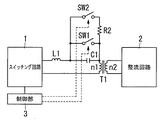
本実施形態は、図8に示すように、実施形態1の構成におけるスイッチSW1に、スイッチSW2と抵抗R2との直列回路を並列に接続した構成を備える。
本実施形態は、実施形態1の変形例であって、図9に示すように、図1に示したインダクタL1に代えて、複数個(図示例は3個)ずつのインダクタL31〜L33とスイッチSW31〜SW33とを用いている。スイッチSW31〜SW33は、それぞれインダクタL31〜L33の個々に並列に接続されている。したがって、スイッチSW31〜SW33のオンオフの組合せによって、インダクタL31〜L33のいずれかが共振回路に用いられる。言い換えると、スイッチSW31〜SW33のオンオフの組合せにより共振回路に用いるインダクタンスが調節され、結果的に複数の共振周波数を選択することが可能になる。
(実施形態4)
本実施形態は、実施形態1の変形例であって、図11に示すように、図1に示したキャパシタC1に代えて、複数個(図示例は3個)ずつのキャパシタC51〜C53とスイッチSW51〜SW53とを用いている。スイッチSW51〜SW53は、それぞれキャパシタC51〜C53の個々に並列に接続されている。したがって、スイッチSW51〜SW53のオンオフの組合せによって、キャパシタC51〜C53のいずれかが共振回路に用いられる。言い換えると、スイッチSW51〜SW53のオンオフの組合せにより共振回路に用いるキャパシタンスが調節され、結果的に複数の共振周波数を選択することが可能になる。
2 整流回路
3 制御部
C1 キャパシタ
C51〜C53 (第2の)キャパシタ
C61〜C63 (第2の)キャパシタ
L1 インダクタ
L31〜L33 インダクタ
L41〜L43 インダクタ
n1 第1巻線
n2 第2巻線
R2 抵抗
SW1 (第1の)スイッチ
SW2 (第2の)スイッチ
SW31〜SW33 (第3の)スイッチ
SW41〜SW43 (第3の)スイッチ
SW51〜SW53 (第4の)スイッチ
SW61〜SW63 (第4の)スイッチ
T1 トランス
Claims (7)
- 入出力間において電力を伝達するトランスと、
前記トランスの一方の巻線と直列に接続された共振用のキャパシタと、
前記トランスの前記一方の巻線と前記キャパシタとの直列回路に流す電流を入切するスイッチング回路と、
前記トランスの他方の巻線に誘起された電力を整流して出力する整流回路と、
前記キャパシタに並列に接続された第1のスイッチと、
前記トランスの前記一方の巻線と前記キャパシタとの直列回路に電流を流す期間および前記第1のスイッチのオンオフを制御する制御部と、
前記キャパシタに並列接続された第2のスイッチおよび抵抗の直列回路とを備え、
前記制御部は、前記第1のスイッチをオフにし前記スイッチング回路の動作周波数を制御する第1の変換回路を構成する動作と、前記第1のスイッチをオンにし前記スイッチング回路から前記トランスの前記一方の巻線への通電期間を制御する第2の変換回路を構成する動作とを選択し、前記第1の変換回路の動作から前記第2の変換回路の動作に移行させる際に、前記第2のスイッチをオンにした後、前記第1のスイッチをオンにする
ことを特徴とする電力変換装置。 - 前記制御部は、前記第1の変換回路の動作と前記第2の変換回路の動作とを切り替える際に、前記スイッチング回路の動作を、前記第1の変換回路の動作と前記第2の変換回路の動作とは異なる動作とする移行期間を設ける
ことを特徴とする請求項1記載の電力変換装置。 - 前記制御部は、前記第1の変換回路の動作における前記スイッチング回路の動作周波数と、前記第2の変換回路の動作における前記トランスの前記一方の巻線への前記スイッチング回路からの通電期間とを、入力電圧と出力電圧との関係に対応付けて記憶しており、
前記第1の変換回路の動作と前記第2の変換回路の動作とを切り替える際に、切替後の入力電圧と出力電圧との関係を、切替前の入力電圧と出力電圧との関係と一致させるように、記憶している動作周波数および通電期間に応じて前記スイッチング回路を制御する
ことを特徴とする請求項1又は2記載の電力変換装置。 - 前記制御部は、前記第1の変換回路の動作における変換効率と、前記第2の変換回路の動作における変換効率とを、入力電圧と出力電圧との電圧比に対応付けて記憶しており、
入力電圧と出力電圧との関係が、前記第1の変換回路の動作と前記第2の変換回路の動作との両方の動作範囲であるときに、記憶している変換効率が高いほうの動作を選択する
ことを特徴とする請求項1〜3のいずれか1項に記載の電力変換装置。 - 前記トランスの前記一方の巻線と前記スイッチング回路との間に接続される共振用のインダクタをさらに備える
ことを特徴とする請求項1〜4のいずれか1項に記載の電力変換装置。 - 前記トランスの前記一方の巻線と前記スイッチング回路との間に接続される共振用の複数個のインダクタと、
前記インダクタのうちの少なくとも1個を短絡する第3のスイッチとをさらに備える
ことを特徴とする請求項1〜4のいずれか1項に記載の電力変換装置。 - 前記キャパシタは、
前記トランスの前記一方の巻線と前記スイッチング回路との間に接続される共振用の複数個の第2のキャパシタと、
前記第2のキャパシタのうちの少なくとも1個を短絡する第4のスイッチとを備える
ことを特徴とする請求項1〜6のいずれか1項に記載の電力変換装置。
Priority Applications (4)
| Application Number | Priority Date | Filing Date | Title |
|---|---|---|---|
| JP2012136174A JP5906418B2 (ja) | 2012-06-15 | 2012-06-15 | 電力変換装置 |
| EP13804652.9A EP2863531A4 (en) | 2012-06-15 | 2013-05-21 | DEVICE FOR CONVERTING ELECTRICAL ENERGY |
| US14/407,910 US9160242B2 (en) | 2012-06-15 | 2013-05-21 | Electric power conversion device |
| PCT/JP2013/003211 WO2013186991A1 (ja) | 2012-06-15 | 2013-05-21 | 電力変換装置 |
Applications Claiming Priority (1)
| Application Number | Priority Date | Filing Date | Title |
|---|---|---|---|
| JP2012136174A JP5906418B2 (ja) | 2012-06-15 | 2012-06-15 | 電力変換装置 |
Publications (2)
| Publication Number | Publication Date |
|---|---|
| JP2014003764A JP2014003764A (ja) | 2014-01-09 |
| JP5906418B2 true JP5906418B2 (ja) | 2016-04-20 |
Family
ID=49757840
Family Applications (1)
| Application Number | Title | Priority Date | Filing Date |
|---|---|---|---|
| JP2012136174A Active JP5906418B2 (ja) | 2012-06-15 | 2012-06-15 | 電力変換装置 |
Country Status (4)
| Country | Link |
|---|---|
| US (1) | US9160242B2 (ja) |
| EP (1) | EP2863531A4 (ja) |
| JP (1) | JP5906418B2 (ja) |
| WO (1) | WO2013186991A1 (ja) |
Families Citing this family (30)
| Publication number | Priority date | Publication date | Assignee | Title |
|---|---|---|---|---|
| US9112422B1 (en) | 2010-03-09 | 2015-08-18 | Vlt, Inc. | Fault tolerant power converter |
| US9859803B2 (en) * | 2013-04-23 | 2018-01-02 | Analog Devices Global | Transformer-based isolated bi-directional DC-DC power converter, and method and controller for using same |
| WO2016012032A1 (en) * | 2014-07-21 | 2016-01-28 | Huawei Technologies Co., Ltd. | Bi-directional dc-dc converter |
| KR101664572B1 (ko) * | 2014-11-06 | 2016-10-10 | 엘지이노텍 주식회사 | 전력변환부 |
| KR102291851B1 (ko) * | 2014-12-29 | 2021-08-23 | 주식회사 솔루엠 | 전원 공급 장치 |
| CN107112903B (zh) * | 2015-02-02 | 2019-03-26 | 三菱电机株式会社 | Dc/dc转换器 |
| DE102015106335A1 (de) | 2015-04-24 | 2016-10-27 | Dr. Ing. H.C. F. Porsche Aktiengesellschaft | Verfahren zum Betreiben eines Gleichstromwandlers |
| JP6141908B2 (ja) * | 2015-05-18 | 2017-06-07 | 東芝デベロップメントエンジニアリング株式会社 | 電流共振型dc−dcコンバータ |
| JP2016226134A (ja) * | 2015-05-29 | 2016-12-28 | 株式会社日立製作所 | 電力変換装置及び電力変換制御法 |
| US9325247B1 (en) * | 2015-10-02 | 2016-04-26 | Vlt, Inc. | Clamped capacitor resonant power converter |
| CN105406724A (zh) * | 2015-12-31 | 2016-03-16 | 西安爱科赛博电气股份有限公司 | 移相控制全桥零电流变换器及直流开关电源 |
| US10158357B1 (en) | 2016-04-05 | 2018-12-18 | Vlt, Inc. | Method and apparatus for delivering power to semiconductors |
| US10785871B1 (en) | 2018-12-12 | 2020-09-22 | Vlt, Inc. | Panel molded electronic assemblies with integral terminals |
| US10903734B1 (en) | 2016-04-05 | 2021-01-26 | Vicor Corporation | Delivering power to semiconductor loads |
| US10277105B1 (en) | 2016-04-05 | 2019-04-30 | Vlt, Inc. | Method and apparatus for delivering power to semiconductors |
| US11336167B1 (en) | 2016-04-05 | 2022-05-17 | Vicor Corporation | Delivering power to semiconductor loads |
| CN106787769A (zh) * | 2017-02-24 | 2017-05-31 | 北京新能源汽车股份有限公司 | 一种双向全桥llc变换电路及汽车 |
| JP2018174648A (ja) | 2017-03-31 | 2018-11-08 | オムロン株式会社 | Llc共振コンバータ |
| JP2019041531A (ja) | 2017-08-28 | 2019-03-14 | オムロン株式会社 | Llc共振コンバータ |
| EP3462589A1 (de) * | 2017-09-29 | 2019-04-03 | Siemens Aktiengesellschaft | Resonanter gleichstromsteller mit integriertem tief- und hochsetzsteller |
| CN108237943B (zh) * | 2018-01-17 | 2019-05-17 | 深圳威迈斯新能源股份有限公司 | 一种双输出端口充电电路及其控制方法 |
| CA3089660C (en) * | 2018-01-29 | 2023-05-16 | Queen's University At Kingston | Resonant power converters and control methods for wide input and output voltage ranges |
| WO2019170781A1 (en) * | 2018-03-06 | 2019-09-12 | Npc Tech Aps | A resonant power converter |
| US11342858B2 (en) | 2018-04-26 | 2022-05-24 | Panasonic Intellectual Property Management Co., Ltd. | Power converter apparatus including LLC resonant circuits and wide range of output voltage with higher efficiency |
| JP6752335B2 (ja) * | 2018-07-10 | 2020-09-09 | シャープ株式会社 | Dc/dcコンバータ |
| US11329542B2 (en) * | 2019-03-01 | 2022-05-10 | Sharp Kabushiki Kaisha | Switching regulator |
| FR3093875A1 (fr) | 2019-03-14 | 2020-09-18 | Safran | Convertisseur de puissance isolé et reconfigurable |
| TWI688195B (zh) * | 2019-06-19 | 2020-03-11 | 宏碁股份有限公司 | 電源供應器 |
| JP2022002454A (ja) * | 2020-06-22 | 2022-01-06 | 富士電機株式会社 | 電力変換装置 |
| JPWO2022190162A1 (ja) * | 2021-03-08 | 2022-09-15 |
Family Cites Families (19)
| Publication number | Priority date | Publication date | Assignee | Title |
|---|---|---|---|---|
| US4951185A (en) | 1989-07-13 | 1990-08-21 | General Electric Company | Resonant inverter employing frequency and phase modulation using optimal trajectory control |
| JP2588786B2 (ja) * | 1990-02-26 | 1997-03-12 | オリジン電気株式会社 | X線電源装置 |
| JPH04125062A (ja) * | 1990-09-12 | 1992-04-24 | Toyota Autom Loom Works Ltd | 直列共振型dc―dcコンバータ |
| US5438497A (en) * | 1993-05-13 | 1995-08-01 | Northern Telecom Limited | Tertiary side resonant DC/DC converter |
| US7212414B2 (en) * | 1999-06-21 | 2007-05-01 | Access Business Group International, Llc | Adaptive inductive power supply |
| CN1236545C (zh) * | 2000-04-28 | 2006-01-11 | Tdk股份有限公司 | 电力变换装置 |
| US6195270B1 (en) * | 2000-06-19 | 2001-02-27 | Technical Witts, Inc. | Self clamping zero voltage switching DC transformers |
| JP4617025B2 (ja) * | 2001-05-29 | 2011-01-19 | キヤノン株式会社 | 共振型電源装置 |
| KR100541724B1 (ko) * | 2002-11-08 | 2006-01-11 | 삼성전자주식회사 | 모터전원공급장치 및 모터전원공급방법 |
| JP4400065B2 (ja) * | 2003-02-26 | 2010-01-20 | オムロン株式会社 | スイッチング電源装置 |
| JP2005065395A (ja) * | 2003-08-11 | 2005-03-10 | Sony Corp | 電源装置 |
| JP4635584B2 (ja) * | 2004-11-30 | 2011-02-23 | Tdk株式会社 | スイッチング電源装置 |
| US7796406B2 (en) * | 2007-07-31 | 2010-09-14 | Lumenis Ltd. | Apparatus and method for high efficiency isolated power converter |
| US7817452B2 (en) * | 2007-08-13 | 2010-10-19 | Stephen William Smith | Phase shifted H-Bridge resonant converter with symmetrical currents |
| JP5241571B2 (ja) * | 2009-03-05 | 2013-07-17 | 富士通テレコムネットワークス株式会社 | スイッチング電源装置 |
| JP5632191B2 (ja) | 2010-04-28 | 2014-11-26 | パナソニック株式会社 | 双方向dc/dcコンバータ |
| GB201013847D0 (en) * | 2010-08-18 | 2010-09-29 | Texas Instr Cork Ltd | Power converter control arrangement |
| CN202218161U (zh) * | 2011-08-30 | 2012-05-09 | 刘闯 | 双向隔离式的移相全桥dc/dc变换器 |
| CN103795251A (zh) * | 2012-10-29 | 2014-05-14 | 台达电子工业股份有限公司 | 功率变换器及其控制方法 |
-
2012
- 2012-06-15 JP JP2012136174A patent/JP5906418B2/ja active Active
-
2013
- 2013-05-21 EP EP13804652.9A patent/EP2863531A4/en not_active Withdrawn
- 2013-05-21 WO PCT/JP2013/003211 patent/WO2013186991A1/ja active Application Filing
- 2013-05-21 US US14/407,910 patent/US9160242B2/en active Active
Also Published As
| Publication number | Publication date |
|---|---|
| WO2013186991A1 (ja) | 2013-12-19 |
| EP2863531A1 (en) | 2015-04-22 |
| EP2863531A4 (en) | 2015-12-02 |
| JP2014003764A (ja) | 2014-01-09 |
| US9160242B2 (en) | 2015-10-13 |
| US20150124490A1 (en) | 2015-05-07 |
Similar Documents
| Publication | Publication Date | Title |
|---|---|---|
| JP5906418B2 (ja) | 電力変換装置 | |
| EP3787171A1 (en) | Isolated dc/dc converters for wide output voltage range and control methods thereof | |
| JP6067116B2 (ja) | Dc/dcコンバータ | |
| JP5762617B2 (ja) | Dc/dcコンバータ | |
| JP5621193B2 (ja) | 電力変換装置 | |
| EP2001113A2 (en) | Isolated high power bi-directional DC-DC converter | |
| JP5089359B2 (ja) | 電力変換装置 | |
| JP2007104872A (ja) | 電力変換器 | |
| JP2008099512A (ja) | 電源装置 | |
| JP2007174784A (ja) | 双方向dc−dcコンバータおよびその制御方法 | |
| JP2011120370A (ja) | 直流―直流双方向コンバータ回路 | |
| JP6526546B2 (ja) | 共振形電源装置 | |
| JP5857998B2 (ja) | 駆動装置および駆動装置を備えた車両 | |
| JP5552149B2 (ja) | コンバータ及び双方向コンバータ | |
| JP2007221892A (ja) | 電力変換装置 | |
| JP6065753B2 (ja) | Dc/dcコンバータおよびバッテリ充放電装置 | |
| JP5678860B2 (ja) | 交流直流変換器 | |
| JP2006081263A (ja) | 双方向dc−dcコンバータ | |
| JP6482009B2 (ja) | 多入力コンバータ及び双方向コンバータ | |
| JP2013212023A (ja) | 双方向電力変換装置 | |
| JPH11113191A (ja) | 無停電電源装置及びその充電制御方法 | |
| JP2000188867A (ja) | コンバータ回路および直流電圧制御用装置 | |
| JP5535290B2 (ja) | 双方向コンバータ | |
| JP3874291B2 (ja) | 電源装置 | |
| JP2015019545A (ja) | 電力変換装置 |
Legal Events
| Date | Code | Title | Description |
|---|---|---|---|
| A711 | Notification of change in applicant |
Free format text: JAPANESE INTERMEDIATE CODE: A711 Effective date: 20141003 |
|
| A621 | Written request for application examination |
Free format text: JAPANESE INTERMEDIATE CODE: A621 Effective date: 20150219 |
|
| A131 | Notification of reasons for refusal |
Free format text: JAPANESE INTERMEDIATE CODE: A131 Effective date: 20151006 |
|
| A521 | Request for written amendment filed |
Free format text: JAPANESE INTERMEDIATE CODE: A523 Effective date: 20151116 |
|
| TRDD | Decision of grant or rejection written | ||
| A01 | Written decision to grant a patent or to grant a registration (utility model) |
Free format text: JAPANESE INTERMEDIATE CODE: A01 Effective date: 20151208 |
|
| A61 | First payment of annual fees (during grant procedure) |
Free format text: JAPANESE INTERMEDIATE CODE: A61 Effective date: 20160106 |
|
| R151 | Written notification of patent or utility model registration |
Ref document number: 5906418 Country of ref document: JP Free format text: JAPANESE INTERMEDIATE CODE: R151 |