EP2388231B1 - Fluidspeicher- und Ausgabesysteme und Verfahren - Google Patents
Fluidspeicher- und Ausgabesysteme und Verfahren Download PDFInfo
- Publication number
- EP2388231B1 EP2388231B1 EP11158779.6A EP11158779A EP2388231B1 EP 2388231 B1 EP2388231 B1 EP 2388231B1 EP 11158779 A EP11158779 A EP 11158779A EP 2388231 B1 EP2388231 B1 EP 2388231B1
- Authority
- EP
- European Patent Office
- Prior art keywords
- liner
- cap
- dispensing
- connector
- fluid
- Prior art date
- Legal status (The legal status is an assumption and is not a legal conclusion. Google has not performed a legal analysis and makes no representation as to the accuracy of the status listed.)
- Active
Links
- 239000012530 fluid Substances 0.000 title claims description 361
- 238000003860 storage Methods 0.000 title claims description 178
- 238000000034 method Methods 0.000 title claims description 72
- 230000008569 process Effects 0.000 title claims description 43
- 239000007788 liquid Substances 0.000 claims description 131
- 239000000523 sample Substances 0.000 claims description 86
- 239000000463 material Substances 0.000 claims description 74
- 238000010168 coupling process Methods 0.000 claims description 55
- 238000005859 coupling reaction Methods 0.000 claims description 55
- 230000008878 coupling Effects 0.000 claims description 54
- 238000004519 manufacturing process Methods 0.000 claims description 30
- 239000004065 semiconductor Substances 0.000 claims description 25
- 239000003153 chemical reaction reagent Substances 0.000 claims description 15
- 230000001404 mediated effect Effects 0.000 claims description 9
- 238000004377 microelectronic Methods 0.000 claims description 5
- 238000005056 compaction Methods 0.000 claims description 4
- 230000000750 progressive effect Effects 0.000 claims description 4
- 238000000605 extraction Methods 0.000 claims description 3
- 239000007789 gas Substances 0.000 description 99
- 230000009471 action Effects 0.000 description 29
- 230000006870 function Effects 0.000 description 29
- -1 e.g. Substances 0.000 description 25
- DNIAPMSPPWPWGF-UHFFFAOYSA-N Propylene glycol Chemical compound CC(O)CO DNIAPMSPPWPWGF-UHFFFAOYSA-N 0.000 description 21
- 230000033001 locomotion Effects 0.000 description 21
- 238000007789 sealing Methods 0.000 description 21
- 238000012360 testing method Methods 0.000 description 19
- 238000012795 verification Methods 0.000 description 19
- 239000010408 film Substances 0.000 description 18
- 230000000694 effects Effects 0.000 description 17
- 229920002120 photoresistant polymer Polymers 0.000 description 17
- 239000012528 membrane Substances 0.000 description 16
- 239000000126 substance Substances 0.000 description 15
- 238000013459 approach Methods 0.000 description 14
- 229920001343 polytetrafluoroethylene Polymers 0.000 description 14
- 239000004810 polytetrafluoroethylene Substances 0.000 description 13
- 230000007246 mechanism Effects 0.000 description 12
- 230000000295 complement effect Effects 0.000 description 11
- 230000008054 signal transmission Effects 0.000 description 10
- 229920001774 Perfluoroether Polymers 0.000 description 9
- 230000008859 change Effects 0.000 description 9
- 238000011109 contamination Methods 0.000 description 9
- 238000012544 monitoring process Methods 0.000 description 9
- 239000002245 particle Substances 0.000 description 9
- 238000013022 venting Methods 0.000 description 9
- 238000010276 construction Methods 0.000 description 8
- 230000001186 cumulative effect Effects 0.000 description 8
- 230000000994 depressogenic effect Effects 0.000 description 7
- 238000009434 installation Methods 0.000 description 7
- 239000004698 Polyethylene Substances 0.000 description 6
- 125000004122 cyclic group Chemical group 0.000 description 6
- 230000006378 damage Effects 0.000 description 6
- 238000012986 modification Methods 0.000 description 6
- 230000004048 modification Effects 0.000 description 6
- 230000002093 peripheral effect Effects 0.000 description 6
- 229920000573 polyethylene Polymers 0.000 description 6
- 238000013519 translation Methods 0.000 description 6
- 239000004743 Polypropylene Substances 0.000 description 5
- 230000008901 benefit Effects 0.000 description 5
- 230000015572 biosynthetic process Effects 0.000 description 5
- 238000000576 coating method Methods 0.000 description 5
- 230000002939 deleterious effect Effects 0.000 description 5
- 229920001155 polypropylene Polymers 0.000 description 5
- 230000004044 response Effects 0.000 description 5
- XKRFYHLGVUSROY-UHFFFAOYSA-N Argon Chemical compound [Ar] XKRFYHLGVUSROY-UHFFFAOYSA-N 0.000 description 4
- IJGRMHOSHXDMSA-UHFFFAOYSA-N Atomic nitrogen Chemical compound N#N IJGRMHOSHXDMSA-UHFFFAOYSA-N 0.000 description 4
- XEEYBQQBJWHFJM-UHFFFAOYSA-N Iron Chemical compound [Fe] XEEYBQQBJWHFJM-UHFFFAOYSA-N 0.000 description 4
- 239000000853 adhesive Substances 0.000 description 4
- 230000001070 adhesive effect Effects 0.000 description 4
- 230000003139 buffering effect Effects 0.000 description 4
- 239000011248 coating agent Substances 0.000 description 4
- 238000001514 detection method Methods 0.000 description 4
- 238000011049 filling Methods 0.000 description 4
- 239000008188 pellet Substances 0.000 description 4
- 238000012545 processing Methods 0.000 description 4
- 230000003134 recirculating effect Effects 0.000 description 4
- 238000000926 separation method Methods 0.000 description 4
- 239000000243 solution Substances 0.000 description 4
- 230000003068 static effect Effects 0.000 description 4
- 235000012431 wafers Nutrition 0.000 description 4
- XLYOFNOQVPJJNP-UHFFFAOYSA-N water Chemical compound O XLYOFNOQVPJJNP-UHFFFAOYSA-N 0.000 description 4
- 238000005303 weighing Methods 0.000 description 4
- 230000002411 adverse Effects 0.000 description 3
- 230000000712 assembly Effects 0.000 description 3
- 238000000429 assembly Methods 0.000 description 3
- 230000006835 compression Effects 0.000 description 3
- 238000007906 compression Methods 0.000 description 3
- 239000000356 contaminant Substances 0.000 description 3
- 238000011143 downstream manufacturing Methods 0.000 description 3
- 238000003780 insertion Methods 0.000 description 3
- 230000037431 insertion Effects 0.000 description 3
- 238000003760 magnetic stirring Methods 0.000 description 3
- 229910052751 metal Inorganic materials 0.000 description 3
- 239000002184 metal Substances 0.000 description 3
- 239000000203 mixture Substances 0.000 description 3
- 239000000047 product Substances 0.000 description 3
- 239000003380 propellant Substances 0.000 description 3
- 230000000717 retained effect Effects 0.000 description 3
- 230000000153 supplemental effect Effects 0.000 description 3
- RYGMFSIKBFXOCR-UHFFFAOYSA-N Copper Chemical compound [Cu] RYGMFSIKBFXOCR-UHFFFAOYSA-N 0.000 description 2
- 239000004812 Fluorinated ethylene propylene Substances 0.000 description 2
- MHAJPDPJQMAIIY-UHFFFAOYSA-N Hydrogen peroxide Chemical compound OO MHAJPDPJQMAIIY-UHFFFAOYSA-N 0.000 description 2
- 101100442776 Mus musculus Decr2 gene Proteins 0.000 description 2
- PXHVJJICTQNCMI-UHFFFAOYSA-N Nickel Chemical compound [Ni] PXHVJJICTQNCMI-UHFFFAOYSA-N 0.000 description 2
- 229930182556 Polyacetal Natural products 0.000 description 2
- 239000004793 Polystyrene Substances 0.000 description 2
- 229920001328 Polyvinylidene chloride Polymers 0.000 description 2
- 230000004913 activation Effects 0.000 description 2
- 239000007864 aqueous solution Substances 0.000 description 2
- 229910052786 argon Inorganic materials 0.000 description 2
- 230000004888 barrier function Effects 0.000 description 2
- 230000002457 bidirectional effect Effects 0.000 description 2
- 238000004891 communication Methods 0.000 description 2
- 239000012141 concentrate Substances 0.000 description 2
- 239000000470 constituent Substances 0.000 description 2
- 229910052802 copper Inorganic materials 0.000 description 2
- 239000010949 copper Substances 0.000 description 2
- 230000007423 decrease Effects 0.000 description 2
- 230000007812 deficiency Effects 0.000 description 2
- 238000013461 design Methods 0.000 description 2
- 239000006185 dispersion Substances 0.000 description 2
- 229920001971 elastomer Polymers 0.000 description 2
- 238000001914 filtration Methods 0.000 description 2
- 231100001261 hazardous Toxicity 0.000 description 2
- 230000002452 interceptive effect Effects 0.000 description 2
- 229910052742 iron Inorganic materials 0.000 description 2
- 239000010410 layer Substances 0.000 description 2
- 238000002156 mixing Methods 0.000 description 2
- 229910052757 nitrogen Inorganic materials 0.000 description 2
- 238000004806 packaging method and process Methods 0.000 description 2
- 230000036961 partial effect Effects 0.000 description 2
- 229920009441 perflouroethylene propylene Polymers 0.000 description 2
- 229920003023 plastic Polymers 0.000 description 2
- 239000004033 plastic Substances 0.000 description 2
- 238000005498 polishing Methods 0.000 description 2
- 229920002239 polyacrylonitrile Polymers 0.000 description 2
- 229920001748 polybutylene Polymers 0.000 description 2
- 229920000642 polymer Polymers 0.000 description 2
- 229920006324 polyoxymethylene Polymers 0.000 description 2
- 229920002223 polystyrene Polymers 0.000 description 2
- 229920002635 polyurethane Polymers 0.000 description 2
- 239000004814 polyurethane Substances 0.000 description 2
- 229920000915 polyvinyl chloride Polymers 0.000 description 2
- 239000004800 polyvinyl chloride Substances 0.000 description 2
- 239000005033 polyvinylidene chloride Substances 0.000 description 2
- 238000005086 pumping Methods 0.000 description 2
- 231100000331 toxic Toxicity 0.000 description 2
- 230000002588 toxic effect Effects 0.000 description 2
- 238000012546 transfer Methods 0.000 description 2
- 230000007704 transition Effects 0.000 description 2
- 238000011144 upstream manufacturing Methods 0.000 description 2
- VHUUQVKOLVNVRT-UHFFFAOYSA-N Ammonium hydroxide Chemical compound [NH4+].[OH-] VHUUQVKOLVNVRT-UHFFFAOYSA-N 0.000 description 1
- 101100456831 Caenorhabditis elegans sams-5 gene Proteins 0.000 description 1
- OYPRJOBELJOOCE-UHFFFAOYSA-N Calcium Chemical compound [Ca] OYPRJOBELJOOCE-UHFFFAOYSA-N 0.000 description 1
- VYZAMTAEIAYCRO-UHFFFAOYSA-N Chromium Chemical compound [Cr] VYZAMTAEIAYCRO-UHFFFAOYSA-N 0.000 description 1
- KRHYYFGTRYWZRS-UHFFFAOYSA-N Fluorane Chemical compound F KRHYYFGTRYWZRS-UHFFFAOYSA-N 0.000 description 1
- 241000237858 Gastropoda Species 0.000 description 1
- DGAQECJNVWCQMB-PUAWFVPOSA-M Ilexoside XXIX Chemical compound C[C@@H]1CC[C@@]2(CC[C@@]3(C(=CC[C@H]4[C@]3(CC[C@@H]5[C@@]4(CC[C@@H](C5(C)C)OS(=O)(=O)[O-])C)C)[C@@H]2[C@]1(C)O)C)C(=O)O[C@H]6[C@@H]([C@H]([C@@H]([C@H](O6)CO)O)O)O.[Na+] DGAQECJNVWCQMB-PUAWFVPOSA-M 0.000 description 1
- ZOKXTWBITQBERF-UHFFFAOYSA-N Molybdenum Chemical compound [Mo] ZOKXTWBITQBERF-UHFFFAOYSA-N 0.000 description 1
- 230000006978 adaptation Effects 0.000 description 1
- 239000012790 adhesive layer Substances 0.000 description 1
- 239000003570 air Substances 0.000 description 1
- 239000000908 ammonium hydroxide Substances 0.000 description 1
- 230000002528 anti-freeze Effects 0.000 description 1
- 239000003963 antioxidant agent Substances 0.000 description 1
- 238000000071 blow moulding Methods 0.000 description 1
- 229910052791 calcium Inorganic materials 0.000 description 1
- 239000011575 calcium Substances 0.000 description 1
- 239000003795 chemical substances by application Substances 0.000 description 1
- 229910052804 chromium Inorganic materials 0.000 description 1
- 239000011651 chromium Substances 0.000 description 1
- 229910017052 cobalt Inorganic materials 0.000 description 1
- 239000010941 cobalt Substances 0.000 description 1
- GUTLYIVDDKVIGB-UHFFFAOYSA-N cobalt atom Chemical compound [Co] GUTLYIVDDKVIGB-UHFFFAOYSA-N 0.000 description 1
- 239000002131 composite material Substances 0.000 description 1
- 230000001010 compromised effect Effects 0.000 description 1
- 229920001577 copolymer Polymers 0.000 description 1
- 230000007547 defect Effects 0.000 description 1
- 239000007857 degradation product Substances 0.000 description 1
- 239000008367 deionised water Substances 0.000 description 1
- 229910021641 deionized water Inorganic materials 0.000 description 1
- 230000001419 dependent effect Effects 0.000 description 1
- 230000008021 deposition Effects 0.000 description 1
- 230000000881 depressing effect Effects 0.000 description 1
- 238000007599 discharging Methods 0.000 description 1
- 238000006073 displacement reaction Methods 0.000 description 1
- 238000005516 engineering process Methods 0.000 description 1
- 238000005530 etching Methods 0.000 description 1
- HQQADJVZYDDRJT-UHFFFAOYSA-N ethene;prop-1-ene Chemical group C=C.CC=C HQQADJVZYDDRJT-UHFFFAOYSA-N 0.000 description 1
- 239000000945 filler Substances 0.000 description 1
- 239000000706 filtrate Substances 0.000 description 1
- 239000010419 fine particle Substances 0.000 description 1
- 229920002313 fluoropolymer Polymers 0.000 description 1
- 239000004811 fluoropolymer Substances 0.000 description 1
- 239000011521 glass Substances 0.000 description 1
- 239000001307 helium Substances 0.000 description 1
- 229910052734 helium Inorganic materials 0.000 description 1
- SWQJXJOGLNCZEY-UHFFFAOYSA-N helium atom Chemical compound [He] SWQJXJOGLNCZEY-UHFFFAOYSA-N 0.000 description 1
- 229910000040 hydrogen fluoride Inorganic materials 0.000 description 1
- 230000006872 improvement Effects 0.000 description 1
- 230000003993 interaction Effects 0.000 description 1
- 230000001788 irregular Effects 0.000 description 1
- 238000005304 joining Methods 0.000 description 1
- 238000002386 leaching Methods 0.000 description 1
- 230000000670 limiting effect Effects 0.000 description 1
- 239000004973 liquid crystal related substance Substances 0.000 description 1
- 238000011068 loading method Methods 0.000 description 1
- 238000007726 management method Methods 0.000 description 1
- WPBNNNQJVZRUHP-UHFFFAOYSA-L manganese(2+);methyl n-[[2-(methoxycarbonylcarbamothioylamino)phenyl]carbamothioyl]carbamate;n-[2-(sulfidocarbothioylamino)ethyl]carbamodithioate Chemical compound [Mn+2].[S-]C(=S)NCCNC([S-])=S.COC(=O)NC(=S)NC1=CC=CC=C1NC(=S)NC(=O)OC WPBNNNQJVZRUHP-UHFFFAOYSA-L 0.000 description 1
- 238000013507 mapping Methods 0.000 description 1
- 230000000873 masking effect Effects 0.000 description 1
- 230000013011 mating Effects 0.000 description 1
- 238000005259 measurement Methods 0.000 description 1
- 229910052750 molybdenum Inorganic materials 0.000 description 1
- 239000011733 molybdenum Substances 0.000 description 1
- 229910052759 nickel Inorganic materials 0.000 description 1
- 230000000149 penetrating effect Effects 0.000 description 1
- 230000002572 peristaltic effect Effects 0.000 description 1
- 238000005191 phase separation Methods 0.000 description 1
- 239000004014 plasticizer Substances 0.000 description 1
- 229920000098 polyolefin Polymers 0.000 description 1
- 238000001556 precipitation Methods 0.000 description 1
- 239000002243 precursor Substances 0.000 description 1
- 230000002028 premature Effects 0.000 description 1
- 238000002360 preparation method Methods 0.000 description 1
- 238000003825 pressing Methods 0.000 description 1
- 230000002250 progressing effect Effects 0.000 description 1
- 230000035755 proliferation Effects 0.000 description 1
- 230000001737 promoting effect Effects 0.000 description 1
- 238000000197 pyrolysis Methods 0.000 description 1
- 238000009877 rendering Methods 0.000 description 1
- 230000003252 repetitive effect Effects 0.000 description 1
- 239000012858 resilient material Substances 0.000 description 1
- 239000012465 retentate Substances 0.000 description 1
- 238000005096 rolling process Methods 0.000 description 1
- 238000005389 semiconductor device fabrication Methods 0.000 description 1
- 239000002002 slurry Substances 0.000 description 1
- 229910052708 sodium Inorganic materials 0.000 description 1
- 239000011734 sodium Substances 0.000 description 1
- 239000007787 solid Substances 0.000 description 1
- 241000894007 species Species 0.000 description 1
- 238000009987 spinning Methods 0.000 description 1
- 239000007921 spray Substances 0.000 description 1
- 238000005507 spraying Methods 0.000 description 1
- 229910001220 stainless steel Inorganic materials 0.000 description 1
- 239000010935 stainless steel Substances 0.000 description 1
- 238000003756 stirring Methods 0.000 description 1
- 238000012422 test repetition Methods 0.000 description 1
- 239000010409 thin film Substances 0.000 description 1
- 238000012549 training Methods 0.000 description 1
- WFKWXMTUELFFGS-UHFFFAOYSA-N tungsten Chemical compound [W] WFKWXMTUELFFGS-UHFFFAOYSA-N 0.000 description 1
- 229910052721 tungsten Inorganic materials 0.000 description 1
- 239000010937 tungsten Substances 0.000 description 1
Images


Classifications
-
- B—PERFORMING OPERATIONS; TRANSPORTING
- B67—OPENING, CLOSING OR CLEANING BOTTLES, JARS OR SIMILAR CONTAINERS; LIQUID HANDLING
- B67D—DISPENSING, DELIVERING OR TRANSFERRING LIQUIDS, NOT OTHERWISE PROVIDED FOR
- B67D7/00—Apparatus or devices for transferring liquids from bulk storage containers or reservoirs into vehicles or into portable containers, e.g. for retail sale purposes
- B67D7/02—Apparatus or devices for transferring liquids from bulk storage containers or reservoirs into vehicles or into portable containers, e.g. for retail sale purposes for transferring liquids other than fuel or lubricants
- B67D7/0288—Container connection means
-
- B—PERFORMING OPERATIONS; TRANSPORTING
- B67—OPENING, CLOSING OR CLEANING BOTTLES, JARS OR SIMILAR CONTAINERS; LIQUID HANDLING
- B67D—DISPENSING, DELIVERING OR TRANSFERRING LIQUIDS, NOT OTHERWISE PROVIDED FOR
- B67D1/00—Apparatus or devices for dispensing beverages on draught
- B67D1/08—Details
-
- B—PERFORMING OPERATIONS; TRANSPORTING
- B67—OPENING, CLOSING OR CLEANING BOTTLES, JARS OR SIMILAR CONTAINERS; LIQUID HANDLING
- B67D—DISPENSING, DELIVERING OR TRANSFERRING LIQUIDS, NOT OTHERWISE PROVIDED FOR
- B67D7/00—Apparatus or devices for transferring liquids from bulk storage containers or reservoirs into vehicles or into portable containers, e.g. for retail sale purposes
- B67D7/02—Apparatus or devices for transferring liquids from bulk storage containers or reservoirs into vehicles or into portable containers, e.g. for retail sale purposes for transferring liquids other than fuel or lubricants
- B67D7/0238—Apparatus or devices for transferring liquids from bulk storage containers or reservoirs into vehicles or into portable containers, e.g. for retail sale purposes for transferring liquids other than fuel or lubricants utilising compressed air or other gas acting directly or indirectly on liquids in storage containers
- B67D7/0255—Apparatus or devices for transferring liquids from bulk storage containers or reservoirs into vehicles or into portable containers, e.g. for retail sale purposes for transferring liquids other than fuel or lubricants utilising compressed air or other gas acting directly or indirectly on liquids in storage containers squeezing collapsible or flexible storage containers
- B67D7/0261—Apparatus or devices for transferring liquids from bulk storage containers or reservoirs into vehicles or into portable containers, e.g. for retail sale purposes for transferring liquids other than fuel or lubricants utilising compressed air or other gas acting directly or indirectly on liquids in storage containers squeezing collapsible or flexible storage containers specially adapted for transferring liquids of high purity
-
- B—PERFORMING OPERATIONS; TRANSPORTING
- B67—OPENING, CLOSING OR CLEANING BOTTLES, JARS OR SIMILAR CONTAINERS; LIQUID HANDLING
- B67D—DISPENSING, DELIVERING OR TRANSFERRING LIQUIDS, NOT OTHERWISE PROVIDED FOR
- B67D7/00—Apparatus or devices for transferring liquids from bulk storage containers or reservoirs into vehicles or into portable containers, e.g. for retail sale purposes
- B67D7/06—Details or accessories
- B67D7/32—Arrangements of safety or warning devices; Means for preventing unauthorised delivery of liquid
- B67D7/3227—Arrangements of safety or warning devices; Means for preventing unauthorised delivery of liquid relating to venting of a container during loading or unloading
-
- B—PERFORMING OPERATIONS; TRANSPORTING
- B67—OPENING, CLOSING OR CLEANING BOTTLES, JARS OR SIMILAR CONTAINERS; LIQUID HANDLING
- B67D—DISPENSING, DELIVERING OR TRANSFERRING LIQUIDS, NOT OTHERWISE PROVIDED FOR
- B67D7/00—Apparatus or devices for transferring liquids from bulk storage containers or reservoirs into vehicles or into portable containers, e.g. for retail sale purposes
- B67D7/06—Details or accessories
- B67D7/32—Arrangements of safety or warning devices; Means for preventing unauthorised delivery of liquid
- B67D7/3281—Details
-
- B—PERFORMING OPERATIONS; TRANSPORTING
- B67—OPENING, CLOSING OR CLEANING BOTTLES, JARS OR SIMILAR CONTAINERS; LIQUID HANDLING
- B67D—DISPENSING, DELIVERING OR TRANSFERRING LIQUIDS, NOT OTHERWISE PROVIDED FOR
- B67D7/00—Apparatus or devices for transferring liquids from bulk storage containers or reservoirs into vehicles or into portable containers, e.g. for retail sale purposes
- B67D7/06—Details or accessories
- B67D7/32—Arrangements of safety or warning devices; Means for preventing unauthorised delivery of liquid
- B67D7/34—Means for preventing unauthorised delivery of liquid
- B67D7/344—Means for preventing unauthorised delivery of liquid by checking a correct coupling or coded information
-
- F—MECHANICAL ENGINEERING; LIGHTING; HEATING; WEAPONS; BLASTING
- F16—ENGINEERING ELEMENTS AND UNITS; GENERAL MEASURES FOR PRODUCING AND MAINTAINING EFFECTIVE FUNCTIONING OF MACHINES OR INSTALLATIONS; THERMAL INSULATION IN GENERAL
- F16K—VALVES; TAPS; COCKS; ACTUATING-FLOATS; DEVICES FOR VENTING OR AERATING
- F16K35/00—Means to prevent accidental or unauthorised actuation
- F16K35/02—Means to prevent accidental or unauthorised actuation to be locked or disconnected by means of a pushing or pulling action
- F16K35/022—Means to prevent accidental or unauthorised actuation to be locked or disconnected by means of a pushing or pulling action the locking mechanism being actuated by a separate actuating element
- F16K35/025—Means to prevent accidental or unauthorised actuation to be locked or disconnected by means of a pushing or pulling action the locking mechanism being actuated by a separate actuating element said actuating element being operated manually (e.g. a push-button located in the valve actuator)
-
- F—MECHANICAL ENGINEERING; LIGHTING; HEATING; WEAPONS; BLASTING
- F16—ENGINEERING ELEMENTS AND UNITS; GENERAL MEASURES FOR PRODUCING AND MAINTAINING EFFECTIVE FUNCTIONING OF MACHINES OR INSTALLATIONS; THERMAL INSULATION IN GENERAL
- F16L—PIPES; JOINTS OR FITTINGS FOR PIPES; SUPPORTS FOR PIPES, CABLES OR PROTECTIVE TUBING; MEANS FOR THERMAL INSULATION IN GENERAL
- F16L37/00—Couplings of the quick-acting type
- F16L37/08—Couplings of the quick-acting type in which the connection between abutting or axially overlapping ends is maintained by locking members
-
- Y—GENERAL TAGGING OF NEW TECHNOLOGICAL DEVELOPMENTS; GENERAL TAGGING OF CROSS-SECTIONAL TECHNOLOGIES SPANNING OVER SEVERAL SECTIONS OF THE IPC; TECHNICAL SUBJECTS COVERED BY FORMER USPC CROSS-REFERENCE ART COLLECTIONS [XRACs] AND DIGESTS
- Y10—TECHNICAL SUBJECTS COVERED BY FORMER USPC
- Y10T—TECHNICAL SUBJECTS COVERED BY FORMER US CLASSIFICATION
- Y10T29/00—Metal working
- Y10T29/49—Method of mechanical manufacture
- Y10T29/49826—Assembling or joining
-
- Y—GENERAL TAGGING OF NEW TECHNOLOGICAL DEVELOPMENTS; GENERAL TAGGING OF CROSS-SECTIONAL TECHNOLOGIES SPANNING OVER SEVERAL SECTIONS OF THE IPC; TECHNICAL SUBJECTS COVERED BY FORMER USPC CROSS-REFERENCE ART COLLECTIONS [XRACs] AND DIGESTS
- Y10—TECHNICAL SUBJECTS COVERED BY FORMER USPC
- Y10T—TECHNICAL SUBJECTS COVERED BY FORMER US CLASSIFICATION
- Y10T29/00—Metal working
- Y10T29/53—Means to assemble or disassemble
Definitions
- the present invention relates to fluid storage and dispensing systems and processes.
- aspects of the invention hereinafter disclosed, relate to various devices, structures and arrangements, as well as processes and methods, for fluid storage and dispensing, and include, without limitation, pre-connect verification couplings that are usefully employed in application to fluid storage and dispensing packages, to ensure proper coupling and avoid fluid contamination issues, empty detect systems that are usefully employed for fluid storage and dispensing packages incorporating liners that are pressure-compressed in the fluid dispensing operation, ergonomically enhanced structures for facilitating removal of a dispense connector from a capped vessel, cap integrity assurance systems for preventing misuse of vessel caps, and keycoding systems for ensuring coupling of proper dispense assemblies and vessels.
- the package may contain a fluid such as a high-purity reagent for use and semiconductor manufacturing.
- a fluid such as a high-purity reagent for use and semiconductor manufacturing.
- the fluid in such application in many instances is costly in character, and/or deleterious in effect if mis-dispensed. For such reason, it is desired that the reagent be conserved against any losses due to wastage, e.g., such as may occur through mis-dispensing of the fluid. Mis-dispensing of the fluid additionally may impair, or even render useless, a semiconductor device that is being manufactured.
- many chemical reagents used in semiconductor manufacturing are very hazardous in character, e.g., being toxic, pyrophoric, corrosive or otherwise harmful in exposure to persons or processing equipment.
- fluid storage and dispensing package it is important for the fluid storage and dispensing package to be coupled with dispensing apparatus in a correct and reliable manner. This is particularly the case in many semiconductor manufacturing operations, where numerous chemical reagent packages are utilized in the course of wafer processing and semiconductor device fabrication, and each such fluid package is coupled to flow circuitry interconnecting the package with the semiconductor tool or other fluid-utilizing apparatus.
- a liner-based fluid storage and dispensing package in which a high-purity chemical reagent is contained in a flexible, polymeric liner, and the liner is disposed inside a rigid outer vessel commonly termed an "overpack."
- a dispensing assembly including a dispense head is coupled with the liner, and pressurizing gas is flowed into the overpack.
- the pressurizing gas exerts compressive force on the liner and progressively collapses the liner under the applied gas pressure, to effect dispensing of fluid from the liner.
- An illustrative package of the above-described type is commercially available from ATMI, Inc. (Danbury, Connecticut) under the trademark NOWPAK®.
- fluid In the original filling of liner packages, fluid conventionally is charged to the liner in a manner producing a nominal headspace that may for example be on the order of 5% of the interior volume of the liner, to accommodate expansion of the fluid during the subsequent storage and transport of the package.
- the headspace thereby provides a small volume of extraneous gas, e.g., air or other ambient gas, above the fluid in the liner. Although small in volume, this headspace gas is deleterious to the contained fluid.
- a primary disadvantage of the headspace gas is that when the liner is subjected to external pressure in the dispensing operation, the resultingly compressed headspace gas solubilizes in the contained fluid to produce dissolved gas therein, in accordance with Henry's Law. The dissolved gas subsequently comes out of solution as the dispense pressure drops along the dispense train in the dispensing operation.
- This liberation of dissolved gas causes irregular and variable dispense profiles of the chemical reagent, e.g., a photoresist that is being flowed to a semiconductor manufacturing tool in a semiconductor manufacturing operation, resulting in the formation of potentially severe wafer defects, bubble formation on surfaces and subsequent popping of such bubbles, etc.
- the presence of significant headspace in the liner entails significant adverse consequences along the entire extent of the fluid delivery path including the final use of the fluid in the process system.
- headspace gas nonetheless has continued to be employed due to its utility as a "measuring fluid" in determining the approach to exhaustion of the fluid inventory in the liner during the latter stages of the dispensing operation.
- the exhaustion of fluid from the liner causes headspace gas to be drawn into the suction train of the dispensing flow circuitry, and this entrainment of headspace gas results in the appearance of bubbles in the downstream liquid flow.
- Initial bubble appearance of the headspace gas is detected in the liquid flow and provides a useful indication that the liquid in the liner is approaching depletion.
- the "first bubble" sensing method of empty detection has proven reliable, but is associated with the inherent disadvantages of headspace gas becoming solubilized in the liquid in the liner and subsequently being released from the liquid during the dispensing operation, since such efflux of gas may give a premature indication of exhaustion of liquid from the liner, thereby preventing maximum utilization of liquid from the liner from being achieved, as well as interfering with the operation of downstream process equipment.
- liner-based fluid storage and dispensing packages of the so-called “bag-in-drum” (BID), “bag-in-can” (BIC) and “bag-in-bottle” (BIB) types are in use, which engage with a dispensing assembly.
- An illustrative dispensing assembly for such purpose is the SMARTPROBE® connector commercially available from ATMI, Inc., Danbury, CT, USA, and), which includes a dispense head (connector body) from which downwardly depends a dip tube that is inserted through a sealing membrane, termed a breakseal, in a fitment associated with the cap port of the liner package.
- U.S. Patent No. 3240399A discloses a dispensing apparatus including a liquid-containing collapsible inner container arranged within a squeezable outer container, an air chamber between the inner and outer container, and a perforated dip tube arranged to permit liquid to be expelled from the inner container upon manual squeezing of the outer container.
- a still further aspect of the invention relates to a method of supplying fluid to a location of use from a liner-based fluid storage and dispensing package including a liner holding said fluid, the method comprising applying exterior pressure to the liner to progressively collapse the liner and dispense fluid therefrom, and monitoring pressure of the dispensed fluid as a function of time to determine slope droop indicative of onset of exhaustion of fluid from the liner during dispensing operation.
- the invention in a further aspect, relates to a fluid storage and dispensing package, comprising a container adapted for holding fluid, said container including a port and a first locking structure on a surface of the container, and a cap adapted for engagement with said port, wherein said cap is adapted for engagement with a dispensing assembly including a dispense connector adapted to cooperatively overfit the cap, said cap having a second locking structure at a lower portion thereof engageable with said locking structure when said dispense connector overfits said cap, and wherein said second locking structure is non-engageable with the first locking structure when said dispense connector does not overfit said cap.
- the invention in another aspect, relates to a fluid storage and dispensing package, comprising a container adapted for holding fluid, said container including a first engagement structure, a cap adapted for engagement with said container, a code ring engageable with said cap to form a cap/code ring assembly, wherein said cap/code ring assembly is adapted for engagement with a dispensing assembly including a dispense connector adapted to cooperatively overfit the cap/code ring assembly for withdrawal of fluid from the container, wherein the cap/code ring assembly includes second engagement structure engageable with said first engagement structure, to fixedly position the cap/code ring assembly on the container and oppose removal thereof.
- a still further aspect the invention relates to a cap including threading for connection thereof to a container having a complementary threading, said cap including non-reuse structure rendering the cap non-reusable subsequent to initial engagement of the cap with the container, said non-reuse structure adapted to deform, destroy or remove said threading upon attempted or effected removal of the cap from the container subsequent to said initial engagement, wherein said non-reuse structure is selected from the group consisting of: toothed locks that cut or tear the area above the threading; arrangements in which attempted removal of the cap results in ripping or destruction of threads; two-piece caps that thread on the neck of the vessel with a detent stop, whereby the threads peel off under high torque when the cap is removed; screw-on caps with anti-rotation features that prevent the cap from being unscrewed; arrangements in which the cap has a tear area above the thread that is activated by unscrewing, in which the remaining threaded area is removed by pulling a vertical tear tab; two-piece threading; tear-off threading;
- a cap including threading for connection thereof to a container having a complementary threading, said cap including a cap modification to prevent removal and/or reuse of the cap, wherein said cap modification is selected from the group consisting of: provision of caps with clips that require a tool to press them into position, wherein the cap when the clip is pressed into position is able to be installed or removed in a ready manner; provision of pins holding the cap in place, with a removal tool being adapted to withdraw the pins out of the position securing the cap; provision of a screw-on cap with pressed-in pins to prevent unscrewing of the cap, wherein the pins can only be removed with a special tool in order to unscrew the cap; provision of a screw-on cap with anti-rotation lock, wherein the code ring must be removed to unlock the cap, and wherein the lock includes pins that must be pulled up or tabs that must be squeezed together to release the lock; provision of a screw-on cap with an anti
- a still further aspect of the invention relates to a method of storage and dispensing of material, in which the material is disposed in a vessel, and a connector is coupled with the vessel, to form a containment package, wherein the connector includes a handle that is translatable between a first locking position in which pressure in the vessel is contained, and a second position in which the connector is removable from the vessel without difference in pressure between the vessel and an ambient environment of the package, such method including selectively depressurizing the vessel while the handle is in the first position, to enable the handle to be translated from the first locking position to the second position.
- the liner 12 may for example be formed as a 3-dimensional, closed head liner.
- the term "3-dimensional" in reference to the liner means that the liner is formed from tubular stock material, as opposed to a 2-dimensional liner formed by heat-sealing superimposed flat sheet stock pieces at superimposed edges thereof to form the liner structure.
- a tubular stock that is retained in tubular form and not slit or cut e.g., a blown tubular polymeric film material retained in tubular form
- heat seals and welded seams along the sides of the liner are avoided.
- the absence of side welded seams may be preferred in some instances to enable the liner to better withstand forces and pressures that may tend to stress the liner and cause failure of seams in 2-dimensional liners.
- a closed-head liner is a liner that has a sealed or otherwise closed head portion, as opposed to an open head liner that is formed with a neck opening or a port opening on the head portion of the liner.
- the liner film preferably is free of components such as plasticizers, antioxidants, fillers, etc. that may be or become a source of contaminants, e.g., by leaching into the liquid contained in the liner, or by decomposing to yield degradation products that have greater diffusivity in the liner film and that migrate to the surface and solubilize or otherwise become contaminants of the liquid in the liner.
- components such as plasticizers, antioxidants, fillers, etc. that may be or become a source of contaminants, e.g., by leaching into the liquid contained in the liner, or by decomposing to yield degradation products that have greater diffusivity in the liner film and that migrate to the surface and solubilize or otherwise become contaminants of the liquid in the liner.
- the liner may be formed of any suitable material of construction, and preferably is formed of a polymeric film.
- the liner may be formed of a suitable fluoropolymer material, such as for example polytetrafluoroethylene (PTFE), fluorinated ethylene propylene (FEP), or perfluoroalkoxy (PFA).
- PTFE polytetrafluoroethylene
- FEP fluorinated ethylene propylene
- PFA perfluoroalkoxy
- the liner may be formed of an olefinic polymer.
- the liner may be formed of a copolymer including any suitable monomeric constituents.
- the liner film may be a single-ply film, or may be formed as a multi-layer laminate or a composite film material, e.g., being coextruded, calendared, or otherwise fabricated with multiple layers or components, e.g., as a multi-layer laminate including one or more intermediate adhesive layers, etc.
- a substantially pure film is utilized for the liner, such as virgin (additive-free) polyethylene film, virgin polytetrafluoroethylene (PTFE) film, or other suitable virgin polymeric material such as polypropylene, polyurethane, polyvinylidene chloride, polyvinylchloride, polyacetal, polystyrene, polyacrylonitrile, polybutylene, etc.
- the thickness of the liner film material can be any suitable thickness, e.g., in a range of from about 1.5 mils (0.0015 inch; 0.0381 mm) to about 30 mils (0.030 inch; 0.762 mm). In one embodiment, the liner has a thickness of 20 mils (0.020 inch; 0.508 mm).
- the liner preferably is of a composition and character that is resistant to particle and microbubble formation when liquid is contained in the liner, and that is effective to maintain purity for the specific end use application in which the liquid is to be employed, e.g., in semiconductor manufacturing or other high purity-critical liquid supply application.
- the liner 12 of the FIG. 1 container contains in its interior space a pellet 45, as illustrated, to aid in non-invasive magnetic stirring of the liquid contents, as an optional feature.
- the pellet may be formed of a metal or other material that is non-deleterious in interaction with the fluid in the liner, or of a material that is coated with an inert film or coating to render the pellet compatible with the fluid.
- the magnetic stirring pellet 45 may be of a conventional type as used in laboratory operations, and can be utilized with an appropriate magnetic field-exerting table, so that the container is able, when reposed on the table with the liner filled with liquid, to be stirred, to render the liquid homogeneous and resistant to settling.
- Such magnetic stirring capability may be employed to resolubilize components of the liquid subsequent to transit of the liquid under conditions promoting precipitation or phase separation of the liquid contents.
- the stirring element being remotely actuatable in such manner has the advantage that no invasive introduction of a mixer to the interior of the sealed liner is necessary.
- the port 30 in deck 26 of the housing 14 can be coupled with a rigid port on the liner, so that the liner is fabricated with two ports, or alternatively the liner can be fabricated so that it is ventable using a single port configuration.
- a radio frequency identification (RFID) tag 32 may be provided on the liner, for the purpose of providing information relating to the contained liquid and/or its intended usage.
- the radio frequency identification tag can be arranged to provide information via a radio frequency transponder and receiver to a user or technician who thereby can ascertain the condition of the liquid in the container, its identity, source, age, intended use location and process, etc.
- RFID device other information storage may be employed which is readable, and/or transmittable, by remote sensor, such as a hand-held scanner, computer equipped with a receiver, etc.
- the liner 12 allows the liquid to expand and contract due to temperature changes.
- zero head space in reference to fluid in a liner means that the liner is totally filled with liquid medium, and that there is no volume of gas overlying liquid medium in the liner.
- head space is desired to be minimized and preferably eliminated (i.e., in a zero or near-zero head space conformation) with complete filling of the interior volume of the liner with liquid medium.
- the port 160 is circumscribed by a cap 128 of cylindrical form defining a central opening 165.
- the top annular surface 166 of the cap 128 features keying elements, including keycode notches 168 and 170, and keycode pin 172.
- keying elements may be employed that provide a suitable keycode structure, and that such elements may include other permutations of a notches and pins, or alternatively any other types of matably engageable structural elements that cooperatively interfit with one another to define a correctly engaged cap and dispenser.
- Examples of other matably engageable structural elements include channel and protrusion elements, interdigitating ribs of circumferentially varied transverse dimensions, tongue and groove elements, and the like.
- the dispenser 134 is shown schematically, as including an upper cylindrical dispenser body 138 and a lower, larger-diameter cylindrical dispenser ring 140.
- the upper cylindrical dispenser body 138 and the lower cylindrical dispenser ring are interconnected with one another, such that the upper dispenser body is biased to a retracted position by suitable biasing structure such as a biasing spring 177.
- suitable biasing structure such as a biasing spring 177.
- the circumferential dispenser ring 140 features keycode elements that are complementary to the keying elements of the cap 128.
- the keycode elements on the dispenser ring 140 include a first pin 180 that is matably engageable with keycode notch 168 of the cap, a second pin 182 that is matably engageable with keycode notch 170 of the cap, and channel 189 in the dispenser interlock 176 that is matably engageable with the pin 172 of the cap.
- the dispenser body 138 is freely translatable against the dispenser ring 140, in a downward direction by application of manual pressure exerted downwardly on the dispenser body 138, or upwardly by release of such manual pressure, as indicated by bidirectional arrow A.
- the dispenser body 138 is schematically illustrated as having a fluid output B associated therewith.
- the fluid output B is in fluid flow communication with the probe 136, to enable delivery of fluid from the liner through the probe and fluid output B to an external location of use, e.g., by flow circuitry joining the fluid output B to such external location.
- the external location may for example include a fluid-utilizing facility such as a semiconductor manufacturing tool, or other installation in which the dispensed fluid is treated, used as a treatment agent, or otherwise employed to facilitate a process or operation.
- the probe 136 has a short length, in relation to the overall height of the package with which the dispensing assembly, including the probe, is associated.
- the probe thus is configured as a "stubby probe,” taken here as denoting that the probe has a longitudinal dimension that places the bottom inlet opening thereof at a position in the upper end portion of the liner, when the dispensing assembly is fully engaged with the cap and associated vessel.
- the probe may have a longitudinal dimension that is on the order of the height dimension of the connector body, or it may even be less than such height dimension of the connector body.
- the liner preferably is constructed as shown, with a top port facilitating headspace gas removal.
- the stubby probe allows the headspace gas to be removed prior to flow of the chemistry from the liner through the dispense network. Further, the ability to remove headspace gas prior to dispensing facilitates achievement of minimal headspace throughout the downstream flow circuitry and at the end-use facility, e.g., semiconductor manufacturing tool, thereby minimizing or avoiding the problems incident to the presence of headspace gas in the source vessel, as well as lines, downstream tanks and reservoirs, feed channels, and the like.
- the use of the stubby probe and the provision of an upper end venting of the liner produces optimal conditions for pressure-dispensing of fluid from the liner, without the occurrence of gross gas voids in the liquid or effervescence of dissolved gas from the liquid as the liquid is subjected to progressively lower pressure in pressure drop segments of the flow circuitry and downstream process network.
- the fluid output B is constituted by a fluid discharge conduit equipped with connection structure to facilitate the interconnection of the fluid discharge conduit with downstream flow circuitry.
- headspace gas When the headspace gas is pressurized during imposition of pressure on the external surface of the liner for fluid dispensing, such pressurized headspace gas goes into solution and thereafter holds the potential for effluxing from the liquid, and introducing headspace gas throughout the downstream system, in addition to headspace gas being entrained in the dispensed liquid, and resulting in slugs of gas that can interfere with pumps, mass flow controllers, and other components of the downstream process system.
- the complete or near-complete venting of headspace gas can be effected, so that the top port can thereby serve in initial removal of headspace gas as well as subsequent discharge of liquid from the package.
- a pressurizing gas is introduced into the interior volume of the overpack outside the liner therein, so that the pressurizing gas exerts a compressive force on the liner, causing it to progressively contract, to pressure-dispense the fluid from the liner.
- the fluid in the liner e.g., a photoresist
- the fluid output B from which it passes into the downstream flow circuitry.
- the dispenser ring 140 initially is engaged with the cap so that the keying elements mate with one another. If the respective keying elements on the ring and the cap do not engage with one another, due to a mis-connection in which a wrong dispenser is attempted to be coupled with the fluid storage and dispensing package 100, the probe 136 is prevented from engaging and puncturing the sealing membrane 162. Accordingly, the attempted connection of the incorrect elements is immediately detected, without the occurrence of contamination of the contained fluid or of the dispenser, such as would otherwise occur in the absence of the keycode structure of the dispenser and cap.
- the engagement of the ring 140 with the cap 28 de-actuates the dispenser interlock 176, and allows the dispenser body 138 to be vertically translated downwardly against the ring 140, by application manual pressure on the dispenser body.
- the dispenser body 138 thereupon is downwardly translated so that the probe 136 engages and punctures the membrane 162, thereby placing the dispenser 134 in condition for dispensing operation involving discharge of fluid from the liner 112 in overpack 114.
- the fluid storage and dispensing system shown in FIG. 2 thus employs a dispenser 134 and package 100 incorporating the pre-connect verification coupling of the invention, as including a first coupling body and a ring cooperative therewith to allow a translational movement of the body against the ring in a post-verification coupling with a second coupling body including second keycode structure, wherein the ring includes a first keycode structure and an interlock preventing such translational movement prior to verification coupling of the first keycode structure with the second keycode structure.
- the term "verification coupling” refers to the first and second keycode structures being sufficiently, and preferably fully, engaged with one another so as to indicate that the first and second keycode structures are complementary and properly fit one another.
- first and second coupling bodies thus may be of any suitable type, e.g., embodied as connectors, matable fittings, engageable lock structures, etc.
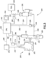
- FIG. 3 is a schematic representation of a process arrangement 250, including a liner-based fluid storage and dispensing package 200 interconnected by flow circuitry with a semiconductor manufacturing tool 238, and an empty detect system according to one embodiment of the present invention.
- the liner-based fluid storage and dispensing package 200 includes a liner 206 that is disposed in the interior volume 204 of a rigid overpack 202.
- the interior volume 204 of the overpack 202 is in fluid communication with a source 212 of a suitable pressurizing gas, by means of the pressurizing gas feed line 210.
- the pressurizing gas can be of any suitable type, such as for example, argon, helium, nitrogen, air, etc., as may be necessary or desirable in a given application of the liner-based fluid storage and dispensing package.
- the liner 206 contains a fluid, such as a photoresist liquid composition, a chemical mechanical polishing slurry, or other suitable fluid composition.
- the liner is coupled in fluid dispensing relationship to the downstream fluid-utilizing semiconductor manufacturing tool 238, by flow circuitry including dispense line 208.
- the dispense line 208 optionally contains a fluid processing, monitoring or control unit 218, as may be necessary or desirable in a specific implementation of the process installation.
- Such unit 218 may be provided with a vent line 219, as necessary or desired in a specific application.
- the liner 206 in such embodiment can be formed of a barrier film that is permeation-resistant to gases in the exterior ambient environment of the liner.
- the liner may be formed of a polytetrafluoroethylene (PTFE) film, to prevent ingress of air or other ambient environment gas species from the gas in contact with the exterior surface of the liner.
- PTFE polytetrafluoroethylene
- the dispensing operation is carried out with flow of pressurizing gas from the source 212 through line 210 into the interior volume 204 of the liner-based package.
- the pressurizing gas exerts pressure on the exterior surface of the liner 206, thereby serving to compress and collapse the liner so that fluid is forced into dispense line 208.
- the filter 220 serves to de-gas the fluid, remove fine particles from the liquid, or otherwise improve the character or quality of the liquid for subsequent use.
- the filter 220 includes a vent line 222 containing flow control valve 224 therein, for venting gas and/or liquid from the filter, as desired.
- the vented stream in line 222 may, for example, be a retentate stream produced by the filtration operation in filter 220.
- the filtrate produced by the filtering in filter 220 is discharged into fluid feed line 226 containing flow control valves 228 and 234 therein, upstream and downstream, respectively, of the dispensing pump 232.
- Flow control valve 228 has associated therewith an automatic valve actuator 230
- flow control valve 234 has associated therewith an automatic valve actuator 236.
- the dispensing pump 232 may be of any suitable type, including diaphragm pumps, piston pumps, peristaltic pumps, injector-type pumps, metered-dose pumps, etc.
- the choice of a specific pump will depend on the character the fluid being dispensed, the requirements of the downstream fluid-utilizing location or facility, the pressure drop in the flow circuitry with which the pump is associated, etc.
- the tool may be of any suitable type, including coating, etching, polishing, masking, deposition, volatilization, pyrolysis, packaging, mixing, abatement or other type tools.
- the fluid dispensing and utilization operations may be carried out in a controlled manner in the process installation illustratively shown in FIG. 3 , using the control system including central processor unit (CPU) 240.
- the CPU may be of any suitable type, such as a general-purpose programmable computer, a microprocessor, microcontroller, programmable logic controller, or the like.
- the CPU is operatively coupled with a pressure transducer 216, connected by a pressure sensing line 214 to the fluid dispense line 208.
- the pressure transducer may be of any suitable type, effective to detect the pressure of dispensed fluid in dispense line 208, and to responsively generate a signal corresponding to the sensed pressure. Such a response signal is transmitted from the transducer 216 in signal transmission line 248 to the CPU.
- the CPU 240 in response to such sensed pressure signal from the transducer 216, may be arranged to responsively adjust components of the process facility, including: pressurized gas source 212, by means of a control signal transmitted in signal transmission line 246 to the source 212; fluid processing, monitoring or control unit 218, by means of a control signal transmitted in signal transmission line 260; valve actuator 230, by means of a control signal transmitted in signal transmission line 252; valve actuator 236, by means of a control signal transmitted in signal transmission line 256; and/or pump 232, by means of a control signal transmitted in signal transmission line 254.
- the various controlled system components may be modulated in response to the dispense pressure sensed by transducer 216.
- the CPU 240 in the FIG. 3 embodiment is arranged to communicate with an output device 244, which may for example include a display monitor 244, linked to the CPU by signal transmission line 242, or other output device or output capability or subsystem.
- an output device 244 which may for example include a display monitor 244, linked to the CPU by signal transmission line 242, or other output device or output capability or subsystem.
- the CPU in one embodiment of the invention is configured and arranged to monitor the pressure of the dispensed fluid, as well as the pressure of the pressurizing gas.
- the source 212 may have associated therewith a pressure transducer operatively coupled to signal transmission line 246, and arranged to transmit a signal to the CPU correlative of the pressure of the pressurizing gas in the source 212.
- the signal transmission line 246 may be a bidirectional signal transmission line or a multi-line cable, capable of transmitting signals both to and from the CPU and the source 212.
- the above-described embodiment of the invention reflects the discovery that when dispensing fluid from a flexible liner by imposition of pressure thereon, the progressive collapse of the liner at the approach to the fully collapsed position (at which fluid is exhausted from the liner) involves a frictional change of the liner in response to applied pressure. Specifically, it has been observed that as the liner is collapsed, near the end-of-dispense at the approach to a fully collapsed position, the liner friction increases for each incremental amount of additional liner collapse.
- the fall-off of the dispensed fluid pressure at the aforementioned relatively lower rate of change marks a transition that is readily discernible in a plot of pressure as a function of time for the dispensed fluid.
- the "slope droop" of the pressure curve thus provides an early indication that the vessel is approaching exhaustion, and such slope droop is followed by a steep slope, as the vessel progresses to an exhausted (empty or substantially empty) state.
- the pump or other motive fluid driver that is coupled with the liner-based package for effecting flow of dispensed fluid through the flow circuitry can be selected or otherwise set to provide a drive pressure that will enable dispensing throughout the full extent of the dispensing operation, i.e., from an initial full state of the liner, progressing to early slope droop pressure behavior, and finally to steep slope decline to an empty or near-empty state.
- the pressure setpoint for the motive fluid driver may be 7 psig
- the motive fluid driver may be a metered dose pump arranged to pump the fluid in a succession of a discrete small volumes, or "shots," as part of a pumping cycle in which a suction step precedes each shot.
- shots discrete small volumes
- the slope of pressure versus time for the dispensed shots begins to fall softly.
- the decline from the (setpoint) pressure of 7 psig to 6 psig provides an early warning indication of the approach to empty.
- the pressure then rapidly declines to about 1.5 psig at the empty state at which no more pumping of liquid is possible.
- an extremely small amount of photoresist, well less than 10 mL in volume, e.g., 5 mL of photoresist remains in the package, representing an overall utilization level of greater than 99.75% of the photoresist originally supplied in the package.
- the empty detect system and methodology based on this end-of-dispense transition in dispensed fluid pressure thus provides sufficient indication of the onset of exhaustion of the fluid in the liner as to minimize, or, in some instances, to even eliminate the requirement of an external reservoir for transitional feed of supplemental fluid to the fluid-utilizing process.
- the hold-up inventory of supplemental fluid is correspondingly minimized or even eliminated, and the overall economics of the process are correspondingly improved.
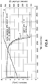
- FIGS. 4-8 are pressure-time graphs that illustrate the dispensing system behavior during fluid dispensing operation, for a liner-type package of the type described in connection with FIG. 3 , in which the motive fluid driver was a shot-dispensing pump operating with alternating suction and positive fluid displacement steps in a repetitive cycle. Pressure profile, dispense shot variability, and final residual liquid were determined in four runs of the system, using deionized water as the test liquid. The dispense rate of the liquid was 5 mL dispensed over six seconds with a shot every 60 seconds (i.e., one 5 mL shot per minute).
- the tests were carried out to capture the profile of the liner-based package pressure decay near the empty state, and to log the dispense shot profile as well as to measure the residual chemical at final empty state.
- the pressurizing gas was clean dry air at a pressure of 7 psig.
- FIG. 4 is a graph of package pressure, in psig, and dispensed fluid weight, in grams, as a function of time, in seconds, for the aforementioned liner-based fluid storage and dispensing package, showing the pressure behavior of the system during a dispensing operation involving the last 250 mL of liquid in the vessel.
- curve A is the package pressure
- curve B is the cumulative weight, in grams, of the dispensed fluid, as determined by weighing of such dispensed fluid.
- an early warning of approach to exhaustion occurred in the vicinity of 2400 seconds, when about 40 mL of water remained for dispensing. The empty state was reached at about 2850 seconds, with 9 mL of residual liquid in the liner.
- FIG. 5 is a graph of package pressure, in psig, and dispensed fluid weight, in grams, as a function of time, in seconds, for the aforementioned liner-based fluid storage and dispensing package, showing the pressure behavior of the system during dispensing operation involving the last 550 mL of liquid in the vessel.
- curve A is the package pressure
- curve B is the cumulative weight, in grams, of the dispensed fluid, as determined by weighing of such dispensed fluid.
- the slope droop indicative of the onset of exhaustion occurred in the vicinity of 6600 seconds of dispensing time. Complete exhaustion of the liner occurred at about 7250 seconds of dispensing time.
- the stepped profile of curve B is readily apparent, and the identity of the step size along the curve reflects the constant volume portions of fluid dispensed in the successive shot-dispensing segments of the pump cycle.
- the profile of curve A reflects pressure drop during the suction cycle, and relaxation after the suction stroke.
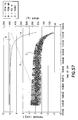
- FIG. 7 is a graph of package pressure, in psig (curve A), and dispensed fluid weight, in grams (curve B), as a function of time, in seconds, for the liner-based fluid storage and dispensing package from which the liquid is dispensed in a series of successive "shots," each containing 1.42 g of the liquid, by the action of the cyclic suction pump.
- the graph shows the data for the last seven dispense shots from the fluid storage and dispensing package during the dispensing operation, as well as the linear equation fitting the data.
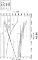
- FIG. 8 is a graph of package pressure, in psig, and dispensed fluid weight, in grams, as a function of time, in seconds, for the liner-based fluid storage and dispensing package from which the liquid is dispensed in a series of successive "shots" by the action of the cyclic suction pump, showing the data for the last four dispense shots from the fluid storage and dispensing package during dispensing operation, as well as the linear equation fitting the data.
- curve A is the package pressure
- curve B is the cumulative weight, in grams, of the dispensed fluid, as determined by weighing of such dispensed fluid.
- the graph shows the dispense profile droop of the package pressure curve during the last four shots of liquid dispensing, reflecting and onset of the depletion of the liquid inventory of the liner, at about 4200 seconds of dispensing time.
- the pressure slope droop that is evidenced by the pressure curve as a function of dispensing time for the fluid being dispensed, as the rate of change of pressure as a function of time begins to significantly increase, provides an empty detect capability of sufficiently early character to permit switch-in of a fresh package of fluid for subsequent dispensing, or otherwise of providing a transitional source of fluid between deployment of successive packages that is considerably smaller than would be required utilizing the "first bubble" empty detect methodology of the prior art.
- the liner-based package may be arranged in the manner shown in FIG. 3 , with a pressure monitor such as a transducer arranged to detect the pressure of fluid in the liner, operatively coupled with a control system configured to initiate appropriate action.
- the control system may be arranged to output to an alarm indicative of the onset of exhaustion of the dispensed fluid, so that change-out of the fluid supply package can be affected in a timely manner, ensuring continuity of operations.
- the control system may be arranged to begin initial preparation for switching the fluid dispensing from a first package to a second, fresh package, so that a "sharp" switch-over can thereafter take place when the first fluid supply package is exhausted.
- the control system may be constructed and arranged to terminate the fluid-utilizing process in a manner closely coordinated with the available inventory of remaining fluid in the liner-based package.
- empty detect system of the invention may be implemented in a wide variety of specific forms, and with variation of the specific actions taken in response to the detection of the onset of liner exhaustion.
- the invention may be practiced in variant forms utilizing the pre-connect verification coupling, as well as the empty detect system, in connection with a liner-based fluid storage and dispensing system that is connected to a downstream fluid-utilizing process in the dispensing operation of the contained fluid.
- the invention contemplates a method of supplying a fluid from a collapsible liner subjected to pressure to effect dispensing of the fluid, such method including monitoring pressure of the dispensed fluid as a function of time, and determining pressure slope droop of the pressure-time function as indicative of a predetermined approach to exhaustion of fluid from the liner, and at the predetermined approach to exhaustion of fluid from the liner, imposing a pressure spike on the liner to effect further dispensing of fluid from the liner.
- fluid dispensed from the liner subsequent to imposition of the pressure spike thereon is flowed to a reservoir for transitional supply of fluid during exhaustion of fluid from the liner, to ensure continuity of dispensing of fluid to the downstream fluid-utilizing apparatus or other location of end use.
- Another aspect of the invention relates to a dispense head connector of a type that is used to couple with a cap of a fluid storage and dispensing vessel.
- the connector is of an ergonomically enhanced character, facilitating its use without the difficulties encountered in the use of the prior art connector.
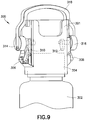
- the invention relates to an ergonomic handle with "push off" features by means of which the connector is readily installed on and removed from a liner-based fluid storage and dispensing package.
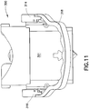
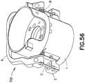
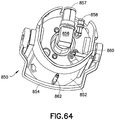
- FIG. 9 there is shown the connector 300 as engaged with a bag in bottle (BIB) vessel 302 including a thin film liner disposed in the interior of the rigid overpack and adapted for holding liquid, e.g., a high purity liquid for semiconductor manufacturing applications.
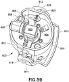
- the connector 300 includes a main body portion 301 having mounted thereon a pivot clamp assembly including pivot clamps 306 and 308, which lockingly engage the cap 304 on the vessel.
- the pivot clamp cams 314 and 316 are coupled with the pivot clamps to allow engagement and disengagement of the clamps depending on the position of the handle 318, which is connected to the pivot clamp cams 314 and 316 as illustrated.
- the pivot clamp cams 314 and 316 each are mounted on associated axles on which also are mounted the push off cams 310 and 312, respectively.
- the ergonomic handle and push off features include several key parts.
- the handle 318 is a finger grooved handle that is easily grasped by a user to secure a firm grip on the connector when it is removed.
- the pivot clamp cams are a primary feature and are used as a rotary cam assembly, which activate the pivot clamps when the pivot clamp cams are rotated upwardly by corresponding movement of the handle. The pivot clamp cams during such rotation ramp up and press the pivot clamps inwardly, which creates a moment about the pivot clamp axis, causing the pivot clamps to be opened/unlocked from the cap 304.
- the pivot clamp cams 314 and 316 as discussed above are coupled with the push off cams 310 and 312, such arrangement allowing the push off cams to push off the top of the cap 304 when the handle 318 is rotated to an up position.
- a gradual change in the cam profile enables a smooth disengagement of the connector 301 from the package.
- the torque spring also ensures that the push off cam is not in an open position. When the push off cam is in a closed position, the connector cannot be placed on the vessel 302, because the push off cam would interfere with the cap 304.
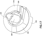
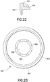
- FIG. 19 is a perspective view of the fitment seal 350 of FIG. 18 , showing the details of the bottom portion thereof.
- the fitment seal 350 includes the disk-shaped main body 351 and cylindrical sealing wall 355.
- a central floor portion 359 of the fitment seal is integrally formed with the main body 351 and forms a central well structure on the top surface of the seal as shown in FIG. 18 and a corresponding protrusion on the bottom surface of the seal as shown in FIG. 19 .
- the main body 351 has a main top surface 352 and a main bottom surface 354.
- the cylindrical sealing wall 355 at its lower end portion has an inwardly tapered outer surface 357.
- the main body 351 includes a central well 360 that is circumscribed by the annular boss 356 protruding upwardly from the main top surface of the body.
- a central floor member 359 has a main top surface 362 in the well, and a corresponding main bottom surface 364 defining a protrusion on the bottom portion of the fitment surrounded by an annular groove 358.
- FIG. 24 is a partial cross-sectional elevation view of a fluid storage and dispensing vessel including the fitment seal of FIGS. 18-19 as positioned to seal a fitment of the vessel.
- the fitment seal E is shown in FIG. 24 as reposed in the port opening of a fitment H, which in turn is coupled to a liner (not shown in FIG. 24 ), and a cap G is shown as engaged with an upper portion of the rigid overpack of the vessel, at complementary threadings of the respective structures.
- a tear tab grip handle C is present as illustrated, and the fitment seal E is constructed to provide a snap fit connection generally represented at D between the fitment seal and the tear tab.
- the fitment seal E provides a circular flange F at its outer peripheral portion for sealing of the fitment H.
- a retainer ring I holds and positions the fitment H with relation to the neck J of the rigid overpack vessel.
- the bottom portion of the downwardly extending cylindrical wall is tapered to ensure a ready insertion of the fitment seal into the fitment.
- the well structure of the central portion of the fitment seal allows the seal to bow or dome when the seal makes contact with the neck of the fitment, and to provide a strong sealing action on the fitment.
- Each finger element 382 has an elongate strip portion 384 that is biased in the absence of force thereon to an outwardly flared position, and terminates at a lower end thereof in a radially inwardly extending lug element 386.
- the finger elements 382 may be formed integrally with the body of the cap, or they may be formed a separate elements that are subsequently secured to the body of the cap, in the cut-outs 380.
- FIG. 27 is a schematic view of a fluid storage and dispensing vessel and associated cap structure and connector body structure, showing the cooperative character thereof.
- the tab element(s) on the cap will spring back to their outwardly biased position, out of position for engagement with the ratchet structure 404.
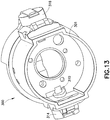
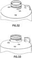
- FIG. 32 is a perspective close-up view of the fluid storage and dispensing vessel 400 of FIG. 28 , showing the details of the anti-rotation locking structure 404 on the neck region 402 of the vessel.
- the neck region 402 may be provided as shown with threading that is complementary to the threading on an inner surface of the cap, whereby the cap may be engaged with the neck of the vessel.
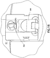
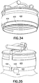
- FIG. 35 is a perspective view of the cap 420 of FIG. 34 , as engaged with the locking structure 418 on the neck region of the fluid storage and dispensing vessel 414 of FIG. 33 .
- the spar element 424 blocks the rotational movement of the cap 422 to the presence of the post locking structure 418 in the channel 422 of the cap.
- FIG. 36 is an elevation view of the cap 420 of FIG. 34 , as engaged with the post locking structure 418 on the neck region of the fluid storage and dispensing vessel of FIG. 33 .
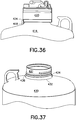
- FIGS. 37-39 Another anti-rotation structure for a cap adapted for engagement with a liner-based fluid storage and dispensing package, as a closure for the package, is shown in FIGS. 37-39 .
- the locking structure includes vertical tab projections on the vessel neck region that block protrusions on the lower part of the cap when the cap is screwed into final position on the vessel.
- FIG. 38 is a perspective view of a cap 440 coupled to the neck of vessel 430, with protrusion 442 of the cap being engaged with the anti-rotation locking tab 434 on the neck region of the vessel.
- the cap in this embodiment is overlaid by the connector 444.
- the currently employed breakseal is replaced by two seals, i.e., a non-wetted gas seal and a readily removable liquid seal.
- the gas seal is constituted by a circular ring that is positioned between the cap and the top of the fitment of the liner. This seal maintains pressure, as applied between the rigid overpack and the liner, from seeping into the center area of the cap where it otherwise could escape by egress from the connector probe entry opening. Gas pressure is required to squeeze the liner in order to effectuate compression of the liner to force the contained fluid out through the probe dispensing assembly.
- the liquid seal is attached to the bottom of a small plug located in the center of the cap.
- the liquid seal is removed when the plug is unscrewed from the cap.
- the probe assembly can then be installed. Additionally, removal of the plug uncovers the hole for access by the probe. Since the pressurization hole is covered and gasketed by the unscrewable center plug, the pressurization hole can be molded completely with good sealing surfaces.
- the probe of the dispensing assembly may be installed without breakage or tearing of a seal. This illuminates the requirement of high puncture forces required in current practice to puncture the breakseal, and avoids the creation of particles that could otherwise enter the high purity fluid in the liner. Additionally, the pressurization holes in the cap in both of the foregoing arrangements are able to be molded smoothly and resultantly to be effectively sealed without leaking.
- the cap is formed of polyethylene coated with a coating of polytetrafluoroethylene to achieve the liquid seal.
- an additional flat gasket is pinched between the inside bottom surface of the cap and the top of the gas seal gasket to effect the liquid seal.
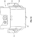
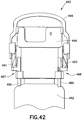
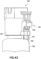
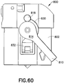
- FIGS. 40-43 Additional embodiments of the invention are shown in FIGS. 40-43 , showing various handle-actuated connector removal arrangements of liner-based fluid storage and dispensing packages having connectors attached thereto, wherein the connector handles are manually operable to effect disengagement of the connectors from the respective fluid storage and dispensing packages.
- FIG. 40 is a perspective view of a portion of a fluid storage and dispensing system 450 including a fluid storage and dispensing vessel 452 to which is secured a dispense connector 454.
- the dispense connector 454 utilizes a single post 460, 461 at each of the respective sides of the connector.
- Handle 455 is secured to the housing of the connector, and is coupled at its respective ends to radial cams 456, 457. As the handle 455 is rotated, the radial cams 406, 407 push the pivot clamps 458 inwardly (pivot clamp 458 being shown, and the system being symmetrically constructed with an additional pivot clamp on the side of the connector 454 opposite the sign shown in FIG. 40 ).
- the handle 476 is secured to the housing of the connector, with respective ends being coupled to cams 484 that are used to transfer the torque of the handle into a vertical force.
- cams 484 that are used to transfer the torque of the handle into a vertical force.
- a profile on the inner side of such part ramps up to press on the pivot clamps 483 in a linear motion.
- Linear springs on each post, together with torque springs, return the handle to its original orientation subsequent to manual translation thereof.
- FIG. 42 is an elevation view of a fluid storage and dispensing system 490 according to another embodiment, in which a linkage arrangement is employed to convert the torque up the handle 496 into a vertical force.
- the linkage centers the force on the double post part 487, 488 associated with posts 485, 486, and allow a single torque spring to be used to return the handle and double post part to a closed position.
- This arrangement also utilizes a linear cam to open the respective pivot clamps 491, 493, and a double post to "push off' the fluid storage and dispensing vessel 492.
- FIG. 43 is an elevation view of a fluid storage and dispensing system according to another embodiment of the invention.
- the system 500 includes a fluid storage and dispensing vessel 502, to which is coupled a connector 504 having on each of opposite sides thereof a side platform 505 associated with a corresponding pivot clamp 508.
- the side platform in each instance includes a double post 506, 507 (the side platform opposite that shown on the right hand side of FIG. 43 being symmetrically constructed and arranged).
- a user would secure both hands on respective sides of the connector body, with the palms in contact with the respective side platforms 505, and gripping the connector body for support.
- the user that applies pressure to the respective side platforms 505 in a squeezing action.
- the respective posts activate the pivot clamps 508 with a linear cam, and the four posts then push off the vessel 502.
- the invention also contemplates in another aspect a cap/code ring assembly with locking tabs and a fluid storage and dispensing vessel matably engageable with such assembly, where in the vessel features locking teeth and a mis-connection interference feature.
- FIG. 44 is an exploded perspective view of such a fluid storage and dispensing package, featuring keycode structure and a mis-connection interference structure to prevent engagement of the fluid storage and dispensing package with an incorrect dispensing connector.
- a fluid storage and dispensing a vessel 510 is provided with a neck 512 having threading F on the exterior surface thereof, for cooperative engagement with threading on an interior surface of the cap D.
- the vessel 510 features an array of locking teeth G on its upper surface in the vicinity of the neck 512, and an interference feature H on such upper surface in the vicinity of the neck 512 for preventing mis-connection of a dispensing connector to the vessel.
- the cap D features locking tabs E on a lower portion of the cap.
- the cap is provided with two or more horizontal locking tabs, circumferentially spaced apart from one another. These locking tabs slip over the locking teeth on the vessel neck when the cap is being screwed on, but grab or "bite” into the locking teeth when attempt is made to unscrew the cap.
- the cap preferably is made of a flexible material of construction, such as for example polyethylene, polypropylene, polytetrafluoroethylene, or the like.
- the locking tabs on the cap are pushed in or activated by a ring extension C of the upper code ring A.
- the cap's locking structure can be forced over the threads and locking teeth of the vessel 510 when the cap is screwed on the neck of the vessel.
- the locking tabs and teeth on the vessel begin to one another due to the angles of their respective mating faces. The interference of these two features locks the cap to the vessel.
- the cap can be removed when necessary by first removing the code ring and its attached lower tab activation ring, code ring extension C.
- An instrument such as a screwdriver can be inserted into slots B in the code ring A, and the code ring then can be prided off.
- the locking tabs can be moved away from the locking teeth on the vessel, following which the cap is easily unscrewed. Since the code ring then is no longer attached to the cap, it cannot be reused on another vessel.
- the mis-connection interference feature H is located on the top surface of the vessel 510 and projects upwardly from such surface. This interference feature is located so that a smart probe assembly will not be contacted when the probe assembly is installed, but the interference feature will otherwise interfere with an incorrect connector during attempted installation thereof.
- the features of the fluid storage and dispensing assembly of FIG. 44 permit the cap and vessel to the assembled in a ready manner, but prevents them from being disassembled by normal means.
- the illustrated arrangement permits removal of the cap by a common tool, viz., a flat blade screwdriver, and the process of removal renders the cap unsuitable for further use.
- the vessel connector interference feature prevents an incorrect connector from being installed on the vessel.
- FIG. 45 is a perspective view of the cap and code ring assembly 515 of the fluid storage and dispensing package shown in FIG. 44 .
- the assembly includes the code ring A coupled with the cap D, and with the code ring extension C circumscribing the cap D.
- FIG. 46 is a bottom plan view of the cap and code ring assembly 515 of the fluid storage and dispensing package shown and FIG. 44 . This view shows the locking tabs being pushed in by the code ring extension C, with the cap D positioned in the cap/code ring assembly.
- the cap is removable from the vessel when necessary, while avoiding the possibility of deleterious reuse of the cap and the keycoding structure ensures that coupling of a correct dispensing connector is achieved and that mis-connection of an inappropriate dispensing connector is avoided.
- Additional aspects relating to cap modification to prevent removal and/or reuse of the cap include the following: provision of caps with clips that require a tool to press them into position, wherein the cap when the clip is pressed into position is able to be installed or removed in a ready manner; provision of pins holding the cap in place, with a removal tool being adapted to which the pins out of the position securing the cap; provision of a screw-on cap with pressed-in pins to prevent unscrewing of the cap, wherein the pins can only be removed with a special tool in order to unscrew the cap; provision of a screw-on cap with anti-rotation lock, wherein the code ring must be removed to unlock the cap, and wherein the like includes pins that must be pulled up or tabs that must be squeezed together to release the lock; provision of a screw-on cap with an anti-rotation lock, in which the code ring must be removed to unlock the cap, wherein the anti-rotation lock is a ratchet type, with teeth on the cap and teeth on
- FIGS. 47-56 show additional dispensing assembly probe connector embodiments of the invention, having an improved ergonomic character to facilitate removal of the probe connector from the fluid storage and dispensing package.
- Currently employed probe assemblies can require the application of 20-30+ pounds of force to effect removal of the probe assembly from the container.
- the ergonomics of the removal operation are uncomfortable and awkward for the operator, requiring the container to be held in one hand while simultaneously the other hand must pinch together the locking clamps and lift the probe assembly from the container.
- the unlatching of the clamps is made more difficult by the fact that the locks do not disengage until the locking clamps have been fully depressed. An operator can often struggle unsuccessfully to remove a probe assembly only to find that the locking clamps have not been fully depressed.
- the probe assemblies of FIGS. 47-56 are designed to minimize such difficulties, and provide an ergonomically improved probe assembly removal.
- FIG. 47 is a perspective view of a connector 550 of a dispensing assembly, according to another embodiment of the invention.
- the connector 550 includes a connector body 552 to which is coupled an ergonomically shaped handle 556 interconnected with cams 558 and 560.
- the cams 558 and 560 in turn coact with pivot clamps 562 and 564, to open the pivot clamps for removal of the connector from the cap 554 when the handle is in a vertically upright position, and to maintain the pivot clamps in a closed condition when the handle is in its down position, such as is shown in FIG. 47 .
- the handle is biased by a return spring (not shown) in the connector body, to a handle down position.
- the handle serves two functions, holding the laches open when the handle is in the up position, and providing an ergonomically enhanced handle for manual gripping and application of force to separate the connector from the package with which it is associated.
- the handle has two attached cam surfaces close to its pivot axis.
- the cams deactivate the pivot clamps that hold the connector to the cap of the package.
- the pivot clamps are held open.
- the handle in a vertical position, it can be manually pulled upwardly to separate the connector from the cap and associated container.
- torsional springs attached to the cams return the handle to its starting position and reactivate the pivot clamps.
- Each of the cams in this embodiment has a cam profile with a rotation center at the handle pivot, in which the contact surface profile of the pivot clamp is matched to that of the handle.
- a torsional spring interconnects the housing of the connector and the handle, and may be of any suitable type that effectively biases the handle to the desired down position.
- the handle cams and pivot clamps are always in contact with one another.
- FIG. 48 is another perspective view of the connector of FIG. 47 , wherein the same parts are correspondingly numbered with respect to those of FIG. 47 , showing the features and details of the handle, connector and pivot clamp elements.
- a small wheel or ball may be provided between the cams and pivot clamps to reduce friction, such as by providing complementary tracks in the cams and pivot clamps, containing ball bearings in the tracks to minimize friction.
- wear-reducing coatings may be applied to the cams and pivot clamps, at their bearing surfaces, for the same purpose.
- FIG. 49 is a front elevation view of a connector 568 of a dispensing assembly, according to yet another embodiment of the invention.
- an ergonomically enhanced handle 569 is mounted on a connector body 570 so that the handle is pivotally movable in relation to the connector body.
- the handle is connected with linkages 572 and 574 to the pivot clamps 576 and 578.
- the connector body 570 is mounted on cap 582 coupled in turn to vessel 580.
- the handle in the FIG. 49 arrangement is associated with a return spring (not shown) and push off features.
- the handle in this arrangement serves the functions of opening the latches, providing an ergonomically enhanced member for manual gripping and application of force to separate the connector from the container, and a riding the linkages that activate the connector push off features.
- the linkages drive the pivot clamps to an open position as well as transmitting force and movement to the push off features.
- This arrangement reduces the force of separation by breaking the static friction of the O-ring seals, moving the connector upward and reducing the distance it must be pulled before it is free of O-ring drag.
- the pivot clamp unlocking feature of this arrangement allows the operator to concentrate fully on separating the connector assembly from the container, without effort in opening the pivot clamps.
- the handle facilitates the ready application of the necessary separation force. When released, the handle will rotate through an arc of 40-60° to a "locked on" position, by action of a torsional spring.
- FIG. 50 is a perspective view of the connector of FIG. 49 , wherein all parts elements are correspondingly numbered.
- FIG. 51 is a side elevation view of a connector 600 of a dispensing assembly, according to yet another embodiment of the invention, in a first position of the handle 606.
- the handle 606 is mounted on connector body 602 and coupled with large secondary cams 608 that are interconnected with clamp activated cams of the type shown in FIGS. 47 and 48 .
- the secondary cams make contact with the top of the container and assist in separating the connector assembly from the container as the handle is rotated to a vertical position.
- the addition of the large secondary push off the cams in this embodiment reduce the force of separation by breaking the static friction of the O-ring seals between the connector and the cap, and translating the connector upwardly, thereby reducing the distance that it must be pulled before it is free of O-ring drag.
- the connector is the unlocked from the cap when the handle is rotated to the vertical position, and a torsional spring in the handle returns the handle to the lowered starting position when the handle is released.
- the large secondary push off cams thus provide a push off action against the container 604, and asked to push the container out of the connector.
- FIG. 53 is a side elevation view of the connector 600 of FIG. 51 , in a third position of the handle 606. In this position, the pivot clamp 610 is shown.
- movement of the handle upwardly to a vertical position effects disengagement of the pivot clamps from the cap, by action of the primary cams, while the secondary cams engage the surface of the container and provide the push off/ disengagement action.
- FIG. 54 is an exploded view of a portion of a dispense connector according to a further embodiment of the invention.
- the dispense connector in this embodiment includes a handle A that is mounted on connector housing B and is attached to cam F by fastener C.
- the handle is biased to a down engaged position by "handle return” torsion spring D.
- Pivot bolt E interconnects the handle A and the cam F.
- the pivot clamps G are provided at each of the sides of the connector housing B, and serve to latch and unlatch the connector from the cap on the fluid storage and dispensing container.
- FIG. 55 is a simplified spatial view of a connector 700 of a dispensing assembly according to yet a further embodiment of the invention.
- the connector 700 includes a handle A too which is coupled a "handle return" torsional spring B and a main drive linkage C.
- Each main drive linkage C is connected to a push off feature D by means of vertical latch linkage E.
- the push off feature D and vertical latch linkage E are connected to the lock arms G, which engaged the cap F having a coding ring H secured thereto.
- FIG. 56 is an assembled perspective view of the connector of FIG. 55 , with a connector body I (not shown in FIG. 55 ) being illustrated, and with all other parts and components of FIG. 56 being numbered correspondingly with respect to the same features of the connector of FIG. 55 .
- the term "downstream dispenser” refers to process equipment that is associated with a fluid-utilizing tool to supply fluid to the tool in a predetermined amount or at a predetermined rate.
- the downstream dispenser made for example include a final dispense pump, e.g., a compressible tube pump, or a flow-metering device, injector, ejector, compressor, the lower, spray head, nozzle, etc.
- the dispensing operation in this application must supply the required photoresist flow through the process filter and into the downstream dispenser, while maintaining a positive downstream dispenser suction pressure and a consistent dispense profile at end-of-dispense (EOD), and chemical utilization desirably on the order of 99.75%.
- the liner utilized in the fluid storage and dispensing system was 4 L in volume, and the greater than 99.75% utilization of chemical required a residual amount of chemical in the liner that is less than 10 mL.
- a Mykrolis Impact PCM filter (0.02 ⁇ m) was utilized in the test.
- the dispense recipe was: 1 mL dispense over 1.5 seconds, 15 second dispense pump suction stroke duration, and a dispense shot cycle recipe sequence repeated once per minute.
- the drive pressure exerted on the liner to effect pressure dispensing was for example about 7 psig.
- test viscosities selected for the test were 1, 3, 10, 20 and 30 centipoise, with two repetitions of each viscosity being tested. Propylene glycol was blended to the required viscosities, as the test liquid.
- Such dispensing pressure and termination pressure can be varied, and the dispensing operation could for example employ a dispense pressure of 10 psig and a termination pressure of 296,5 hPa (4,3 psig).
- the residual chemical was measured by a liner removal and liquid squeeze out and measurement.
- the test was designed to go to a pressure below that which would be used in a coating tool, such that decay in the dispense profile mass can be identified, and actual utilization prior to the onset of dispense profile decay determined.
- Pressurizing air at 10 psig was connected to the dispense probe for pressurizing of the liner.
- 3500 mL of liquid was simultaneously dispensed through the reservoir separator (which enabled separation and venting of gas from the liquid being dispensed, to achieve a zero or near-zero headspace condition), and the filter vent by the SMC LVH 20L-S07 manual PFA valves, and the system control board was started.
- the last 500 mL of the dispense was logged.
- the test was terminated when the Entegris model 4210 pressure transducer reached 90 hPa (1.3 psig).
- the PFA petcock then was closed and the liner taken off line.
- the liner was removed and the contents were measured after the latter was cut and the remaining propylene glycol was removed, being weighed before and after squeegee removal.
- the 500 mL dispense effluent was measured for viscosity and recorded (28 centipoise at 23° C. was determined for the first run). A new liner then was filled with test fluid and the process was repeated.
- FIG. 57 is a graph of pressure, in psig, as a function of time (time of day), showing the pressure of the dispensed liquid (curve A), the pressure of the pressurizing gas (curve B), the inlet downstream dispenser pressure (curve C) and weight, in grams, of cumulative dispensed liquid measured at the scale (curve D), for representative Run 1 at viscosity of 25 centipoise/28 centipoise, during a time period of 13:12:00 to 18:00:00.
- FIG. 88 is a graph of pressure, in psig, as a function of time (time of day), showing the pressure of the dispensed liquid (curve A), the pressure of the pressurizing gas (curve B), the inlet downstream dispenser pressure (curve C) and weight, in grams, of cumulative dispensed liquid measured at the scale (curve D), and the linear (scale) curve (curve E), for representative Run 1 at viscosity of 25 centipoise/28 centipoise, during a time period of 17:02:24 to 17:45:36.
- the downstream dispenser in pressure is much lower and susceptible to spikes as a result of the pressure decay across the filter, suggesting that the primary pressure transducer be positioned downstream of the filter, e.g., in the downstream dispenser itself.
- the invention in another aspect relates to a connector for a material storage and dispensing package, such as a liner-based package, in which the connector has a safety locking device associated therewith.
- a material storage and dispensing vessel having a connector secured thereto is disassembled while the vessel contains a material at super-atmospheric pressure
- the resulting release of pressure can result in pressure-mediated dispersion of vessel contents to the ambient environment of the vessel.
- the disassembly of the connector from an associated vessel can result in the chemical reagent being sprayed in all directions, posing a major hazard when the chemical reagent is toxic or otherwise deleterious in character.
- the invention addresses this safety issue in one embodiment of the invention, by the provision of a connector having a safety-locking feature to prevent a user from disconnecting the connector from the associated vessel while the vessel is under pressure.
- a lock and/or pressure relief action therefore is provided to ensure that the connector is not blown off from a pressurized package by inadvertent opening or otherwise.
- the invention in one embodiment provides a connector for a material storage and dispensing package.
- the connector includes a main body portion, including a handle mounted on the main body portion and pivotally translatable thereon, between an up position, and a down position.
- the connector is adapted to be coupled with a material storage and dispensing vessel for closure thereof, and includes a dispensing assembly for dispensing material from the vessel, and a pressure relief device operatively coupled with the handle and adapted when the handle is in the down position to prevent removal of the connector from the material storage and dispensing vessel.
- a stop element is operatively coupled with the pressure relief device to maintain the handle in the down position when the handle is pivotally translated to such down position.
- the stop element is selectively disengageable to cause the pressure relief device to vent the vessel to an ambient pressure, and to allow the handle to be pivotally translated upwardly, with the connector thereafter being disengageable from the vessel when the handle is in the up position, whereby disengagement of the connector from the vessel is enabled to occur at the ambient pressure.
- a pressure relief device is operatively coupled with the handle at each of opposite ends thereof.
- the handle at its opposite ends comprises axle portions coupled with the main body portion of the connector.
- the connector includes two stop elements, and each of the axle portions includes a cam surface engageable with a corresponding one of the stop elements.
- Each of the stop elements comprises a button that is spring-biased to a locking position preventing movement of the handle, and that is manually depressible to disengage the button from its locking position, and thereupon to enable movement of the handle.
- the stop element in one embodiment includes a slide member that is manually translatable between a locking position engaged with the handle, and a release position.
- the stop element alternatively can include a cylinder that is selectively actuatable to cause extension of a protrusion element for engagement with the handle, and is de-actuatable to cause retraction of the protrusion element disengaging same from the handle.
- the protrusion element may be constructed and arranged to engage an axle portion of the handle, and the protrusion element may be translated by action of a biasing spring coupled with the protrusion element.
- the package including the vessel and the connector may include a liner in the vessel, with the connector having a dispense port for coupling to flow circuitry or other transport structure for delivery of the dispensed material to a locus of use of same.
- the connector may also include a pressure-assist port for coupling to a source of pressurized gas, to exert pressure on the liner in the vessel for compaction thereof, so that the material-containing liner progressively is made smaller in volume as the liquid or other contained material is correspondingly dispensed from the package.
- the invention therefore contemplates a method of storage and dispensing of material, in which the material is disposed in a vessel, and a connector is coupled with the vessel, to form a containment package, wherein the connector is of a type as described hereinabove, with a handle that is translatable between a first locking position in which pressure in the vessel is contained, and a second position in which the connector is removable from the vessel without difference in pressure between the vessel and ambient environment of the package.
- the method includes selectively depressurizing the vessel while the handle is in the first position, to enable the handle to be translated from the first locking position to the second position.
- Such three-way valve safety feature may be integrated into a connector through the release lever, e.g., a translatable handle of the connector.
- the three-way valve can be located on the connector body, e.g., on a peripheral portion thereof.
- a notch can be provided in the release lever to allow the device to open when the release lever is in a down position. A user then would have to push the button in to actuate the vessel venting, in order to remove the connector from the vessel.
- the button functions to prevent pivotal rotation of the release lever, so that the connector cannot be removed from the vessel when the vessel is pressurized, except when the button is depressed.
- a three-way pressure relief device is employed to lock the release lever, by action of a slide member that engages the release lever in a locked position when the connector is engaged with a vessel and the release lever is translated to a down position.
- the slide then must be translated upwardly to disengage the slide from the release lever, so that the release lever can be pivotally rotated to permit disengagement of the connector from the vessel.
- the upward translation of the slide member then will actuate the pressure relief valve to vent the container and permit safe disengagement of the connector from the vessel.
- a cylinder or linear actuator can be employed as a locking device for the connector.
- the cylinder would be actuated to extend when a pressurized condition is present, and the cylinder would retract by spring biasing action, when the vessel is depressurized or at ambient pressure.
- FIG. 59 is a perspective view of a connector 800 according to one embodiment of the present invention.
- the connector 800 includes a main housing portion 802 having a top main surface 804 on which is disposed a dispensing fitting 805 defining an open end 806 as a dispensing port, to which can be coupled tubing or other flow circuitry, for conveyance of dispensed material to a downstream locus of use.
- the connector 800 includes a release lever in the form of handle 810 which has respective axle portions 812 and 814 that are pivotally secured to the housing 802. This arrangement allows pivotal rotational movement of the handle 810 from the fully down position shown in the drawing, to a fully up position in which the handle is vertically oriented, extending upwardly above the main body portion 802.
- the connector 850 shown in FIG. 64 includes a housing 852 having a top surface including a dispense fitting 856 defining a dispense port 857, and a pressurizing fitting 858 through which a pressurized gas may be directed to facilitate egress of material from a vessel associated with the connector.
- the cylinder 862 thus can be actuated to translate the cylinder or a projection member thereof downwardly against handle 854, to lock the handle in position against further movement.
- FIG. 66 is a perspective view of the connector shown in FIGS. 64 and 65 , wherein all part and elements are correspondingly numbered.
- the cylinder 860 on the top surface of the connector has a protruding portion that is translatable to effect engagement with the axle of the handle 854, so as to lock same in position.
- the axle of the handle may have an opening or cavity therein, which is engaged by the projection portion of cylinder 860, to restrain the handle 854 against movement.
Landscapes
- Engineering & Computer Science (AREA)
- Mechanical Engineering (AREA)
- General Engineering & Computer Science (AREA)
- Containers And Packaging Bodies Having A Special Means To Remove Contents (AREA)
- Closures For Containers (AREA)
- Feeding, Discharge, Calcimining, Fusing, And Gas-Generation Devices (AREA)
- Packages (AREA)
- Loading And Unloading Of Fuel Tanks Or Ships (AREA)
Claims (12)
- Verbindungsstück (138), das zum Koppeln mit einer eine zusammenlegbare Auskleidung (112, 206) beinhaltenden Fluidspeicher- und -abgabeeinheit (100, 200) ausgelegt ist,
dadurch gekennzeichnet, dass
das Verbindungsstück (138) eine eine Öffnung beinhaltende Sonde (136) umfasst, die zur Platzierung in einem oberen Abschnitt eines Innenvolumens der Auskleidung (112, 206) zur Extraktion von Prozessmaterial aus dem oberen Abschnitt des Innenvolumens der Auskleidung (112, 206) eingerichtet ist,
die Sonde (136) dafür ausgelegt ist, Prozessmaterial an ein Prozesssystem zu liefern und
die Sonde (136) dafür eingerichtet ist, Gas aus dem Innenvolumen der Auskleidung (112, 206) aufzunehmen und das Gas an eine Entlüftungsöffnung (219) zu liefern. - Verbindungsstück (138) nach Anspruch 1, das mit einer Gasquelle (212) zur Lieferung von Druckgas in die Einheit (100, 200) koppelbar ist, um zur druckvermittelten Abgabe von Prozessmaterial aus der Auskleidung (112, 206) auf die Auskleidung (112, 206) Druck auszuüben.
- Verbindungsstück (138) nach einem der Ansprüche 1 oder 2, wobei die Sonde (136) in dem Innenvolumen oberhalb eines Füllstands von Prozessmaterial positioniert ist, um vor der Abgabe von Prozessmaterial aus dem Innenvolumen der Auskleidung (112, 206) eine Extraktion von Gas aus dem Innenvolumen der Auskleidung (112, 206) durch die Öffnung der Sonde (136) zu gestatten.
- Verbindungsstück (138) nach einem der Ansprüche 1 bis 3, wobei es sich bei der Sonde (136) um eine Kurzsonde (136) mit einem in einem oberen Abschnitt des Innenvolumens der Auskleidung (112, 206) angeordneten Endstück handelt und das Endstück die Öffnung der Sonde (136) beinhaltet.
- Verbindungsstück (138) nach einem der Ansprüche 1 bis 4, wobei die Einheit ein im Wesentlichen starres Gehäuse (114, 202), das die Auskleidung (112, 206) enthält, und eine mit dem Gehäuse (114, 202) verbundene Kappe (128) beinhaltet und wobei das Verbindungsstück (138) eine erste Schlüsselcodestruktur (180, 182, 189) umfasst, die dafür eingerichtet ist, komplementär zu einer mit der Kappe (128) verbundenen zweiten Schlüsselcodestruktur (168, 170, 172) zu passen, um eine korrekte Ausrichtung des Verbindungsstücks (138) mit der Kappe (128) nachzuweisen.
- Fluidspeicher- und -abgabeeinheit (100, 200), umfassend ein im Wesentlichen starres Gehäuse (114, 202), eine in dem Gehäuse (114, 202) angeordnete zusammenlegbare Auskleidung (112, 206) und ein Verbindungsstück (138) nach einem der Ansprüche 1 bis 5.
- Fluidspeicher- und -abgabeeinheit (100, 200) nach Anspruch 6, die in der zusammenlegbaren Auskleidung (112, 206) ein flüssiges Reagens umfassendes Prozessmaterial mit minimalem Kopfraum enthält.
- Fluidspeicher- und -abgabeeinheit (100, 200) nach einem der Ansprüche 6 oder 7, ferner umfassend eine auf das Gehäuse (114, 202) aufgesetzte Kappe (128), wobei die Kappe (128) eine Anti-Wiederverwendungsstruktur umfasst, die dafür ausgelegt ist, nach erstmaliger Verbindung der Kappe (128) mit dem Gehäuse (114, 202) die Kappe (128) für eine Wiederverwendung unbrauchbar zu machen.
- Fluidspeicher- und -abgabeeinheit (100, 200) nach einem der Ansprüche 6 bis 8, die mit einer Druckgasquelle zur Lieferung von Druckgas in die Einheit gekoppelt ist, um zur druckvermittelten Abgabe von Prozessmaterial aus der Auskleidung (112, 206) Druck auf die Auskleidung (112, 206) auszuüben.
- Verfahren zum Herstellen eines Halbleiter- oder Mikroelektronikprodukts, umfassend eine Verwendung von ein fluides Reagens umfassendem Prozessmaterial und ein Zuführen des Prozessmaterials aus einer Fluidspeicher- und -abgabeeinheit (112, 206), die eine das Prozessmaterial fassende Auskleidung (121, 206) beinhaltet, an ein Prozesswerkzeug (238) zur Herstellung von Halbleiter- oder Mikroelektronikeinrichtungen, wobei die Auskleidung (121, 206) zur Druckabgabe des Prozessmaterials während des Zuführens einer Beaufschlagung mit externem Druck unterzogen wird,
dadurch gekennzeichnet, dass
die Fluidspeicher- und -abgabeeinheit (112, 206) ein Verbindungsstück (138) nach Anspruch 1 umfasst,
im Kopfraum befindliches Gas vor der Abgabe von Prozessmaterial aus der Auskleidung (121, 206) aus dem oberen Abschnitt des Innenvolumens der Auskleidung (121, 206) durch die Öffnung abgezogen und an eine Entlüftungsöffnung geliefert wird und die Auskleidung (121, 206) während der Druckabgabe des Prozessmaterials in einem Zustand mit bei Null oder nahezu Null liegendem Kopfraum gehalten wird. - Verfahren nach Anspruch 10, wobei die Druckabgabe durch ein Beaufschlagen der Auskleidung (121, 206) mit Druckgas erfolgt, um diese nach und nach zu verdichten.
- Verfahren nach einem der Ansprüche 10 oder 11, wobei zwischen der Fluidspeicher-und -abgabeeinheit (100, 200) und dem Prozesswerkzeug (238) zur Herstellung von Halbleiter- oder Mikroelektronikeinrichtungen ein Strömungskreislauf (208, 226) bereitgestellt wird und wobei während der Druckabgabe des Prozessmaterials in dem Strömungskreislauf (208, 226) ein minimaler Kopfraum beibehalten wird.
Applications Claiming Priority (3)
| Application Number | Priority Date | Filing Date | Title |
|---|---|---|---|
| US68789605P | 2005-06-06 | 2005-06-06 | |
| EP06772070.6A EP1896359B1 (de) | 2005-06-06 | 2006-06-05 | Fluidspeicher- und abgabesysteme und -verfahren |
| PCT/US2006/021622 WO2006133026A2 (en) | 2005-06-06 | 2006-06-05 | Fluid storage and dispensing systems and processes |
Related Parent Applications (3)
| Application Number | Title | Priority Date | Filing Date |
|---|---|---|---|
| EP06772070.6A Division EP1896359B1 (de) | 2005-06-06 | 2006-06-05 | Fluidspeicher- und abgabesysteme und -verfahren |
| EP06772070.6A Division-Into EP1896359B1 (de) | 2005-06-06 | 2006-06-05 | Fluidspeicher- und abgabesysteme und -verfahren |
| EP06772070.6 Division | 2006-06-05 |
Publications (3)
| Publication Number | Publication Date |
|---|---|
| EP2388231A2 EP2388231A2 (de) | 2011-11-23 |
| EP2388231A3 EP2388231A3 (de) | 2012-03-07 |
| EP2388231B1 true EP2388231B1 (de) | 2018-09-26 |
Family
ID=37498968
Family Applications (4)
| Application Number | Title | Priority Date | Filing Date |
|---|---|---|---|
| EP11158779.6A Active EP2388231B1 (de) | 2005-06-06 | 2006-06-05 | Fluidspeicher- und Ausgabesysteme und Verfahren |
| EP06772070.6A Active EP1896359B1 (de) | 2005-06-06 | 2006-06-05 | Fluidspeicher- und abgabesysteme und -verfahren |
| EP11158801.8A Not-in-force EP2388233B1 (de) | 2005-06-06 | 2006-06-05 | Fluidspeicher- und Ausgabesysteme und Verfahren |
| EP11158789.5A Active EP2388232B9 (de) | 2005-06-06 | 2006-06-05 | Prozessflüssigkeitspendesystem und -methode |
Family Applications After (3)
| Application Number | Title | Priority Date | Filing Date |
|---|---|---|---|
| EP06772070.6A Active EP1896359B1 (de) | 2005-06-06 | 2006-06-05 | Fluidspeicher- und abgabesysteme und -verfahren |
| EP11158801.8A Not-in-force EP2388233B1 (de) | 2005-06-06 | 2006-06-05 | Fluidspeicher- und Ausgabesysteme und Verfahren |
| EP11158789.5A Active EP2388232B9 (de) | 2005-06-06 | 2006-06-05 | Prozessflüssigkeitspendesystem und -methode |
Country Status (9)
| Country | Link |
|---|---|
| US (4) | US20100112815A1 (de) |
| EP (4) | EP2388231B1 (de) |
| JP (3) | JP5475990B2 (de) |
| KR (3) | KR20080039373A (de) |
| CN (3) | CN102126696B (de) |
| MY (1) | MY142284A (de) |
| SG (2) | SG162759A1 (de) |
| TW (1) | TWI429580B (de) |
| WO (1) | WO2006133026A2 (de) |
Families Citing this family (125)
| Publication number | Priority date | Publication date | Assignee | Title |
|---|---|---|---|---|
| TW468283B (en) * | 1999-10-12 | 2001-12-11 | Semiconductor Energy Lab | EL display device and a method of manufacturing the same |
| US8905266B2 (en) | 2004-06-23 | 2014-12-09 | Ecolab Inc. | Method for multiple dosage of liquid products, dosing apparatus and dosing system |
| EP1879829B1 (de) | 2005-04-25 | 2016-04-20 | Advanced Technology Materials, Inc. | Eine auskleidung aufweisende flüssigkeitslagerungs- und -ausgabesysteme mit leerzustand-erfassungsvermögen |
| JP5475990B2 (ja) * | 2005-06-06 | 2014-04-16 | アドバンスド テクノロジー マテリアルズ,インコーポレイテッド | 液体媒体供給システム及び液体媒体供給方法 |
| WO2008040567A1 (en) * | 2006-10-03 | 2008-04-10 | Artelis | Flexible mixing bag, mixing device and mixing system |
| US8039073B2 (en) * | 2005-12-20 | 2011-10-18 | E.I. Du Pont De Nemours And Company | Pipe preformed liner comprising metal powder |
| US8336734B2 (en) | 2006-06-13 | 2012-12-25 | Advanced Technology Materials, Inc. | Liquid dispensing systems encompassing gas removal |
| CA3049238C (en) | 2006-07-07 | 2023-01-24 | Fair Oaks Farms Brands, Inc. | Method for dispensing a liquid |
| US8277745B2 (en) | 2007-05-02 | 2012-10-02 | Ecolab Inc. | Interchangeable load cell assemblies |
| FR2915974B1 (fr) | 2007-05-11 | 2009-07-10 | Isolateur Denominateur Commun | Conteneur souple de transfert et procede de fabrication. |
| EP2188190B1 (de) | 2007-08-28 | 2011-10-12 | Entegris, Inc. | Verfahren und vorrichtung zur ausgabe von fluiden |
| WO2009059324A2 (en) * | 2007-11-02 | 2009-05-07 | Entegris, Inc. | O-ringless seal couplings |
| SG188849A1 (en) * | 2007-12-07 | 2013-04-30 | Advanced Tech Materials | Blow molded liner for overpack container and method of manufacturing the same |
| NO329053B1 (no) * | 2008-04-30 | 2010-08-02 | Multisense As | Tappekran for montering pa beholder inneholdende vaeske, fremgangsmate for registrering av vaeskenivaet i en slik beholder samt anvendelse av tappekranen. |
| US8100293B2 (en) * | 2009-01-23 | 2012-01-24 | Formulatrix, Inc. | Microfluidic dispensing assembly |
| US20110095027A1 (en) * | 2009-04-15 | 2011-04-28 | New Pig Corporation | Latching Drum Lid With Integral Exhaust Hood |
| JP5421643B2 (ja) * | 2009-04-17 | 2014-02-19 | 光雄 皆川 | 液体の収容容器、及びその収容容器を使用した塗装装置 |
| EP2441084B1 (de) | 2009-06-10 | 2016-09-21 | Entegris, Inc. | Fluidverarbeitungssysteme und -verfahren |
| USRE48951E1 (en) | 2015-08-05 | 2022-03-01 | Ecolab Usa Inc. | Hand hygiene compliance monitoring |
| CN102548868B (zh) * | 2009-07-09 | 2014-12-10 | 先进技术材料股份有限公司 | 基于衬里的存储系统和将流体材料输送给半导体工艺的方法 |
| US9102509B2 (en) * | 2009-09-25 | 2015-08-11 | Ecolab Inc. | Make-up dispense in a mass based dispensing system |
| US9051163B2 (en) | 2009-10-06 | 2015-06-09 | Ecolab Inc. | Automatic calibration of chemical product dispense systems |
| WO2011046802A2 (en) * | 2009-10-14 | 2011-04-21 | Advanced Technology Materials, Inc. | Material storage and dispensing system and method with degassing assembly |
| JP5560019B2 (ja) * | 2009-11-04 | 2014-07-23 | 株式会社アイセロ | 送液装置、およびその送液装置に用いる液体容器 |
| US9150961B2 (en) * | 2009-11-16 | 2015-10-06 | Fei Company | Gas delivery for beam processing systems |
| US8763855B1 (en) * | 2009-12-07 | 2014-07-01 | Hydrochem Llc | Mounted bladder for storage tank |
| US8733598B2 (en) | 2009-12-30 | 2014-05-27 | Advanced Technology Materials, Inc. | Closure/connector for liner-based dispense containers |
| US20120291627A1 (en) * | 2010-01-06 | 2012-11-22 | Advanced Technology Materials, Inc. | Liquid dispensing systems with gas removal and sensing capabilities |
| US8511512B2 (en) | 2010-01-07 | 2013-08-20 | Ecolab Usa Inc. | Impact load protection for mass-based product dispensers |
| EP2405164A1 (de) * | 2010-07-08 | 2012-01-11 | Anheuser-Bush Inbev NV | Elastischer Verschluss für druckbetriebene Ausgabebehälter |
| TWI590992B (zh) | 2010-10-15 | 2017-07-11 | 恩特葛瑞斯股份有限公司 | 用於基於襯底的總成之連接器、用於分配基於襯底的總成之內容物的方法及用於分配基於襯底的總成之內容物的系統 |
| CN103249644B (zh) | 2010-10-27 | 2016-05-18 | 高级技术材料公司 | 用于去除杂质的基于衬里的组件 |
| EP2447205A1 (de) * | 2010-10-29 | 2012-05-02 | AB InBev NV | Ausgabevorrichtung mit entfernbarer Ausgabekartusche |
| TW201242670A (en) | 2010-11-23 | 2012-11-01 | Advanced Tech Materials | Liner-based dispenser |
| CN103261042A (zh) * | 2010-12-10 | 2013-08-21 | 高级技术材料公司 | 用于压力分配系统中的大致圆柱形内衬及其制造方法 |
| US9211993B2 (en) | 2011-03-01 | 2015-12-15 | Advanced Technology Materials, Inc. | Nested blow molded liner and overpack and methods of making same |
| US20120245729A1 (en) * | 2011-03-24 | 2012-09-27 | Gojo Industries, Inc. | Network enabled dispenser |
| US8556183B2 (en) * | 2011-07-08 | 2013-10-15 | Gregory D. Bray | Systems and methods involving transferable identification tags |
| KR101305145B1 (ko) * | 2011-08-16 | 2013-09-12 | (주)에스티글로벌 | 무선통신을 이용하여 약액의 상태를 제어하는 약액 도포 시스템 |
| WO2013028746A2 (en) | 2011-08-22 | 2013-02-28 | Advanced Technology Materials, Inc. | Substantially rigid collapsible container with fold pattern |
| EP2766281A4 (de) * | 2011-10-13 | 2015-05-27 | Advanced Tech Materials | Versand-und ausgabebehälter mit auskleidung zur weitgehenden sterilen aufbewahrung, sendung, und ausggabe von materialien |
| SG11201402260PA (en) * | 2011-11-18 | 2014-09-26 | Advanced Tech Materials | Closure/connectors for liner-based shipping and dispensing containers and methods for filling liner-based shipping and dispensing containers |
| KR20190062600A (ko) * | 2011-12-21 | 2019-06-05 | 어드밴스드 테크놀러지 머티리얼즈, 인코포레이티드 | 라이너에 기초한 운송 및 공급 시스템들 |
| KR20140129062A (ko) | 2012-02-17 | 2014-11-06 | 어드밴스드 테크놀러지 머티리얼즈, 인코포레이티드 | 중합체계 다층 가스 배리어 필름 |
| KR20140130704A (ko) | 2012-02-24 | 2014-11-11 | 어드밴스드 테크놀러지 머티리얼즈, 인코포레이티드 | 유체 전달 시스템 및 방법 |
| USD702128S1 (en) | 2012-04-12 | 2014-04-08 | Advanced Technology Materials, Inc. | Packaging |
| US10642286B2 (en) * | 2012-04-20 | 2020-05-05 | Nordson Corporation | Device, system, and method for tracking the configuration or operational history of a nozzle in a fluid jetting system |
| US20140256234A1 (en) * | 2012-04-27 | 2014-09-11 | Chukar Waterjet, Inc. | System for Dispensing Abrasive Particles in a Liquid Jet Apparatus |
| NL2009237C2 (en) * | 2012-07-26 | 2014-01-28 | Heineken Supply Chain Bv | Connecting device and tapping assembly as well as a container and method for beverage dispensing. |
| CN103675155B (zh) * | 2012-09-14 | 2015-06-17 | 中国石油化工股份有限公司 | 一种顶空轻烃样品保存系统及方法 |
| US9739272B2 (en) | 2012-11-29 | 2017-08-22 | Fair Oaks Farms Brands, Llc | Liquid product dispensing system and method |
| US9296212B2 (en) | 2012-11-29 | 2016-03-29 | Hewlett-Packard Development Company, L.P. | Ink tank parts |
| US20140197180A1 (en) * | 2013-01-16 | 2014-07-17 | Jean LaPoint | Heated mug |
| EP2767447B1 (de) * | 2013-02-18 | 2020-10-07 | Volvo Car Corporation | Fahrzeug mit einer Fahrzeugflüssigkeitsfüllanordnung |
| US8887959B2 (en) | 2013-02-18 | 2014-11-18 | Nicholas Hill | Systems for storing beverages |
| CN105377717A (zh) * | 2013-03-04 | 2016-03-02 | 维佳创新有限公司 | 液体喷射分配器系统 |
| US9625434B2 (en) * | 2013-05-21 | 2017-04-18 | Hach Company | Dripless, permanent sealing assembly for container |
| US20140360135A1 (en) * | 2013-06-07 | 2014-12-11 | Chris Allen Honegger | Bags, Method of Making Bags and Method of Use Thereof for Enveloping Rectangular Bales |
| US8881932B1 (en) * | 2013-06-25 | 2014-11-11 | Quantum Fuel Systems Technology Worldwide, Inc. | Adapterless closure assembly for composite pressure vessels |
| USD745320S1 (en) | 2013-06-28 | 2015-12-15 | Nicholas Hill | Container closure system with handle |
| KR102272693B1 (ko) * | 2013-07-11 | 2021-07-05 | 어드밴스드 테크놀러지 머티리얼즈, 인코포레이티드 | 액체를 충진 및 분배하기 위한 장치 및 방법 |
| WO2015022402A1 (en) * | 2013-08-14 | 2015-02-19 | Basf Se | Coupling device |
| RU2671652C2 (ru) * | 2013-09-13 | 2018-11-06 | Микро Матик А/С | Устройство розлива напитков и способ применения данного устройства розлива напитков |
| SG11201602114RA (en) | 2013-09-20 | 2016-04-28 | Advanced Tech Materials | Apparatus and method for pressure dispensing of high viscosity liquid-containing materials |
| EP3054823B1 (de) | 2013-10-11 | 2021-06-16 | Gehl Foods, LLC | Nahrungsmittelausgabevorrichtung und ventil |
| WO2015058090A1 (en) | 2013-10-18 | 2015-04-23 | Advanced Technology Materials, Inc. | Dip tube assemblies and methods of manufacturing the same |
| US9359711B2 (en) * | 2013-11-06 | 2016-06-07 | Ultimate Dryer Vent Llc | Dryer vent hose assembly |
| CN105899437B (zh) | 2013-11-26 | 2018-01-23 | 恩特格里斯公司 | 用于分配系统的配件和配件适配器及其制造方法 |
| WO2015085214A1 (en) † | 2013-12-06 | 2015-06-11 | Pendo TECH | Sensor fitting for biotech process bag |
| DE202014001720U1 (de) * | 2014-02-27 | 2015-03-02 | Gerhard Brugger | Spender |
| EP2923998A1 (de) * | 2014-03-24 | 2015-09-30 | Anheuser-Busch InBev S.A. | Integrierter KEG-Verbinder |
| JP5588574B1 (ja) * | 2014-06-03 | 2014-09-10 | 日揮株式会社 | アイソレータシステム、及び反応設備 |
| USD792164S1 (en) | 2014-08-29 | 2017-07-18 | Gehl Foods, Llc | Food dispenser |
| CA161168S (en) | 2014-08-29 | 2015-12-01 | Gehl Foods Inc | Valve |
| WO2016033498A1 (en) * | 2014-08-29 | 2016-03-03 | Gehl Foods, Inc. | Food product dispenser and valve |
| US10494169B2 (en) | 2014-10-17 | 2019-12-03 | Entegris, Inc. | Packaging for dip tubes |
| CN107408271A (zh) | 2015-02-12 | 2017-11-28 | 恩特格里斯公司 | 智能封装 |
| US9823263B2 (en) * | 2015-05-01 | 2017-11-21 | Abbott Laboratories | Apparatus for removing liquid contents of a container having a key activated sliding lock and method therefore |
| FR3038864A1 (fr) * | 2015-07-13 | 2017-01-20 | Dover Europe Sarl | Brassage de l'encre dans une cartouche |
| US10274472B2 (en) * | 2015-08-27 | 2019-04-30 | Nuclear Filter Technology, Inc. | Sensor device for a hazardous waste container |
| USD795029S1 (en) | 2015-08-28 | 2017-08-22 | Gehl Foods, Llc | Tool |
| CN105384135B (zh) * | 2015-12-22 | 2018-08-31 | 行愿环保科技有限公司 | 一种智能型液体的运输存储系统 |
| US10399713B2 (en) * | 2016-01-19 | 2019-09-03 | Dr. Py Institute Llc | Devices and methods for formulation processing |
| JP5995213B1 (ja) * | 2016-03-07 | 2016-09-21 | Co2システムズ株式会社 | 滅菌水製造装置 |
| CN105927814A (zh) * | 2016-07-12 | 2016-09-07 | 上海锐迈五金有限公司 | 一种法兰泄漏保护装置 |
| BR112018076663A2 (pt) * | 2016-07-27 | 2019-04-02 | Aleksandrovich Buchik Sergei | interruptor de fluxo de um dispositivo para servir manualmente bebidas espumantes e gaseificadas |
| US10023450B2 (en) | 2016-08-22 | 2018-07-17 | Joseph Jeffries | Boom truck bucket remote control assembly |
| US10294012B2 (en) * | 2016-10-24 | 2019-05-21 | Samsung Electronics Co., Ltd. | Fluid dispenser |
| AT519376B1 (de) | 2016-11-21 | 2018-08-15 | Georg Hagleitner Hans | In eine Behälteröffnung einsetzbares Verschlusselement |
| PL3558861T3 (pl) * | 2016-12-22 | 2024-04-02 | Basf Se | Urządzenie z sondą do łączenia i otwierania pojemników |
| EP3593334B1 (de) | 2017-03-07 | 2021-10-27 | Ecolab Usa Inc. | Überwachungsmodule für handhygienespender |
| US10315814B2 (en) * | 2017-08-04 | 2019-06-11 | Canon Kabushiki Kaisha | Transfer cap |
| US10787358B2 (en) * | 2017-10-09 | 2020-09-29 | Knappco, LLC | Control systems for liquid product delivery vehicles |
| CN107700810B (zh) * | 2017-10-11 | 2018-08-28 | 江西爱米家涂料有限公司 | 一种环保涂料装置 |
| CN107497370B (zh) * | 2017-10-11 | 2018-06-19 | 福州佳宸生物科技有限公司 | 一种化学试剂装备 |
| CN107583560B (zh) * | 2017-10-11 | 2018-10-16 | 宁海利航机电设备设计有限公司 | 一种环保涂料装置 |
| WO2019098734A1 (ko) * | 2017-11-17 | 2019-05-23 | 주식회사 이너보틀 | 액체를 저장할 수 있는 용기장치 및 이것의 제조방법 |
| KR102580650B1 (ko) | 2018-01-22 | 2023-09-20 | 삼성전자주식회사 | 디스펜서용 언더필 용액 공급 장치, 이를 갖는 디스펜서 및 이를 이용한 반도체 모듈의 제조 방법 |
| CN108840306A (zh) * | 2018-06-29 | 2018-11-20 | 浙江正诚机械有限公司 | 油管自动伸缩式税控燃油加油机 |
| JP2020018536A (ja) * | 2018-07-31 | 2020-02-06 | オリンパス株式会社 | 内視鏡及び内視鏡の防水キャップ |
| US20200064177A1 (en) * | 2018-08-21 | 2020-02-27 | Roth River, Inc. | Systems and methods for stored liquid monitoring |
| WO2020047845A1 (zh) * | 2018-09-07 | 2020-03-12 | 石榴创新有限公司 | 分配控制装置和分配设备 |
| JP7515462B2 (ja) | 2018-09-18 | 2024-07-12 | エアグラフト インコーポレイテッド | 気化器セキュリティ及びトレーサビリティ管理のための方法及びシステム |
| US11293551B2 (en) | 2018-09-30 | 2022-04-05 | ColdQuanta, Inc. | Break-seal system with breakable-membrane bridging rings |
| WO2020077455A1 (en) * | 2018-10-16 | 2020-04-23 | Airgraft Inc. | Methods and systems for filling a prepackaged container |
| CA3123862A1 (en) | 2018-12-20 | 2020-06-25 | Ecolab Usa Inc. | Adaptive route, bi-directional network communication |
| EP3902754A4 (de) * | 2018-12-26 | 2022-09-28 | Entegris, Inc. | Einlage für eine umverpackungsanordnung |
| CN109760939B (zh) * | 2019-01-15 | 2020-04-03 | 江山市艺康化学有限公司 | 一种五氧化二磷运输保护桶 |
| JP7482140B2 (ja) * | 2019-01-24 | 2024-05-13 | ハウプト レムス ブリックス アンダース | 流体蠕動層ポンプ |
| EP3712106A1 (de) * | 2019-03-21 | 2020-09-23 | Riprup Company S.A. | Lebensmittelergänzungsbehälter |
| US10935477B2 (en) | 2019-03-27 | 2021-03-02 | Ford Motor Company | Method and apparatus for automatic detection of entrapped gas bubble location and repairing the same in dispensed adhesives, sealants, and mastics |
| CN110164798B (zh) * | 2019-05-29 | 2021-05-25 | 无锡胜脉电子有限公司 | 基于陶瓷基板表的封装气压报警控制系统 |
| WO2020250467A1 (ja) * | 2019-06-14 | 2020-12-17 | 株式会社ダイゾー | 吐出装置 |
| JP7299831B2 (ja) * | 2019-10-18 | 2023-06-28 | 株式会社ダイゾー | 吐出装置 |
| KR102321569B1 (ko) * | 2019-07-10 | 2021-11-05 | 주식회사 아성정공 | 분무액통 고정구조 |
| WO2021026660A1 (en) | 2019-08-13 | 2021-02-18 | Airgraft Inc. | Methods and systems for heating carrier material using a vaporizer |
| US11635148B2 (en) | 2019-12-27 | 2023-04-25 | Horizon Healthcare LLC | Tube clamp |
| US11674617B2 (en) | 2019-12-27 | 2023-06-13 | Horizon Healthcare LLC | Tube lock |
| US11691257B2 (en) * | 2020-08-27 | 2023-07-04 | Jock J. Crump | End cap removal device for a central water plant |
| KR102537815B1 (ko) * | 2021-03-09 | 2023-05-31 | 주식회사 에이티아이케이 | 타이트레이터 시약 저장소용 캐미컬 공급장치 |
| TWI780625B (zh) * | 2021-03-16 | 2022-10-11 | 力晶積成電子製造股份有限公司 | 液體供應系統及液量輔助判斷方法 |
| KR20230010914A (ko) * | 2021-07-13 | 2023-01-20 | (주)딥블루 | 위험물 용기용 라이너백 어셈블리 |
| CN113760020B (zh) * | 2021-09-26 | 2023-06-02 | 北京北方华创微电子装备有限公司 | 半导体设备的压力控制装置及半导体设备 |
| CN113786795B (zh) * | 2021-10-21 | 2022-12-30 | 广州卡洛莱化妆品有限公司 | 一种具有滋润皮肤修饰肤色效果的组合物的生产系统 |
| US11898700B2 (en) * | 2022-03-07 | 2024-02-13 | Suburban Manufacturing, Llc | Machine lubrication system |
Citations (3)
| Publication number | Priority date | Publication date | Assignee | Title |
|---|---|---|---|---|
| US3240399A (en) * | 1963-08-14 | 1966-03-15 | Ned W Frandeen | Dispensing receptacle |
| EP1031533A1 (de) * | 1999-02-26 | 2000-08-30 | Air Liquide Electronics Systems | Flüssigkeitsabgabevorrichtung und Verwendung zum Abgeben einer hochreinen Flüssigkeit |
| EP1391416A1 (de) * | 2002-08-22 | 2004-02-25 | Illinois Tool Works Inc. | Behälter mit Flüssigkeit enthaltendem Quetschbeutel |
Family Cites Families (122)
| Publication number | Priority date | Publication date | Assignee | Title |
|---|---|---|---|---|
| US3214054A (en) * | 1963-04-15 | 1965-10-26 | Bastion Blessing Company | Locking ring for demountable bowls subjected to pressure |
| US3756459A (en) | 1971-01-12 | 1973-09-04 | Damon Corp | Method and apparatus for metering fluid utilizing pressure differentials |
| US3756367A (en) | 1972-01-10 | 1973-09-04 | Ammco Tools Inc | Hydraulic brake system bleeder |
| US4024897A (en) * | 1975-09-18 | 1977-05-24 | Allied Chemical Corporation | Fail-safe interlock system |
| US4109677A (en) * | 1975-12-01 | 1978-08-29 | Burnside Richard E | Protective device for storage tanks |
| JPS6013659A (ja) * | 1983-06-21 | 1985-01-24 | アサヒビール株式会社 | 飲料容器 |
| US4676404A (en) | 1983-10-17 | 1987-06-30 | Nippon Zeon Co., Ltd. | Method and apparatus for feeding drug liquid from hermetic returnable can |
| JPS60139799U (ja) * | 1984-02-28 | 1985-09-14 | 三洋電機株式会社 | 液体切れ検知装置 |
| GB8506559D0 (en) | 1985-03-13 | 1985-04-17 | Tpt Ltd | Liquid container & dispenser |
| US5049349A (en) | 1985-12-13 | 1991-09-17 | The Procter & Gamble Company | Method for making a blown bag-in-box composite container |
| US4696840A (en) | 1985-12-13 | 1987-09-29 | The Procter & Gamble Company | Blown bag-in-box composite container and method and apparatus for making the same |
| US6406276B1 (en) * | 1986-03-04 | 2002-06-18 | Deka Products Limited Partnership | Constant-pressure fluid supply system with multiple fluid capability |
| JPS63252538A (ja) | 1987-04-09 | 1988-10-19 | Mitsubishi Electric Corp | 薬液供給装置 |
| US5035339A (en) * | 1987-04-28 | 1991-07-30 | Vmc Industries, Inc. | Universal sprayer canister |
| JPH01162352A (ja) | 1987-12-18 | 1989-06-26 | Hitachi Chem Co Ltd | 半導体類の封止法 |
| US5102010A (en) * | 1988-02-16 | 1992-04-07 | Now Technologies, Inc. | Container and dispensing system for liquid chemicals |
| US4871087A (en) * | 1988-04-04 | 1989-10-03 | Johnson David S | Reusable container dispenser for ultra high purity chemicals and method of storage |
| JPH01162352U (de) * | 1988-04-27 | 1989-11-13 | ||
| US5129415A (en) | 1989-03-26 | 1992-07-14 | Robert Richard Runyon | System and method for automatically selecting one of a plurality of liquid supply receptacles as a source for a liquid dispensing apparatus |
| US5370269A (en) | 1990-09-17 | 1994-12-06 | Applied Chemical Solutions | Process and apparatus for precise volumetric diluting/mixing of chemicals |
| US5148945B1 (en) * | 1990-09-17 | 1996-07-02 | Applied Chemical Solutions | Apparatus and method for the transfer and delivery of high purity chemicals |
| US5693017A (en) | 1991-02-14 | 1997-12-02 | Wayne State University | Apparatus and method of delivery of gas-supersaturated solutions to a delivery site |
| EP0576604B1 (de) | 1991-03-22 | 2000-01-12 | Deka Products Limited Partnership | Gleichdruckfluidzufuhrsystem mit mehrflüssigkeitsfähigkeit |
| JPH05128383A (ja) | 1991-11-08 | 1993-05-25 | Hitachi Home Tec Ltd | 自動通報装置 |
| DE69312526D1 (de) * | 1992-02-24 | 1997-09-04 | Aeroquip Corp | Abgabevorrichtung für Flüssigkeiten |
| JPH05253461A (ja) | 1992-03-10 | 1993-10-05 | Chiyoda Kizai Kk | 薬液圧送装置 |
| JP2884909B2 (ja) * | 1992-05-13 | 1999-04-19 | 日本電気株式会社 | 薬品供給装置 |
| JP2999071B2 (ja) * | 1992-08-12 | 2000-01-17 | 麒麟麦酒株式会社 | バッグインボックス用袋体及びバッグインボックス |
| US5335821A (en) * | 1992-09-11 | 1994-08-09 | Now Technologies, Inc. | Liquid chemical container and dispensing system |
| US5526956A (en) | 1992-09-11 | 1996-06-18 | Now Technologies, Inc. | Liquid chemical dispensing and recirculating system |
| US5957328A (en) * | 1992-09-11 | 1999-09-28 | Now Technologies, Inc. | Liquid chemical dispensing and recirculating system |
| JP3362878B2 (ja) | 1992-10-29 | 2003-01-07 | 日本板硝子株式会社 | 液状流体搬送装置 |
| JPH06247499A (ja) * | 1993-02-19 | 1994-09-06 | Hoechst Japan Ltd | 液状化学薬品用二重容器及び該容器を用いるcvd装置への液状化学薬品の供給方法 |
| US5425404A (en) * | 1993-04-20 | 1995-06-20 | Minnesota Mining And Manufacturing Company | Gravity feed fluid dispensing system |
| US5878793A (en) | 1993-04-28 | 1999-03-09 | Siegele; Stephen H. | Refillable ampule and method re same |
| US5607002A (en) | 1993-04-28 | 1997-03-04 | Advanced Delivery & Chemical Systems, Inc. | Chemical refill system for high purity chemicals |
| US5555996A (en) * | 1993-08-06 | 1996-09-17 | Rehrig Pacific Company | Bag-in box with split lid |
| JP2613176B2 (ja) | 1994-05-25 | 1997-05-21 | 株式会社崇洋堂 | 流体用缶の注出構造 |
| JPH0995311A (ja) * | 1994-06-30 | 1997-04-08 | Ishii Shokuhin Kk | 袋詰包装機の包装袋の脱気方法 |
| KR0136644B1 (ko) | 1994-09-07 | 1998-04-25 | 공희택 | 반도체 제조공정의 고순도 케미칼 이송로에 설치되는 테프론 여과막을 갖는 필터의 프리웨팅 방법 및 장치 |
| CN1161250A (zh) | 1995-02-11 | 1997-10-08 | Pkl包装系统有限公司 | 一种计量预定量液体的装置和方法 |
| GB9507844D0 (en) * | 1995-04-18 | 1995-05-31 | Kodak Ltd | Improvements relating to the collection of process effluent |
| US5570815A (en) * | 1995-06-06 | 1996-11-05 | International Business Machine Corp. | Chemical delivery system |
| JPH0926350A (ja) | 1995-07-12 | 1997-01-28 | Morii Hidemaru | 液浸形感知部分に関する電極の構造 |
| US5968014A (en) | 1995-08-25 | 1999-10-19 | Debiotech S.A. | Continuously operating infusion device and method |
| JPH09104481A (ja) * | 1995-10-11 | 1997-04-22 | Lion Corp | 内容物の加圧排出方法 |
| JP3405059B2 (ja) * | 1995-10-18 | 2003-05-12 | 凸版印刷株式会社 | フレキシブルバッグの搬送充填方法およびその装置 |
| US5861060A (en) * | 1996-01-11 | 1999-01-19 | Binks Sames Corporation | Supply tank for electrostatic spraying system |
| WO1998005853A1 (en) | 1996-08-07 | 1998-02-12 | Cuno, Inc. | Additive dispensing apparatus |
| US5799830A (en) * | 1996-11-08 | 1998-09-01 | Carroll; David C. | Pressure vessel access port |
| US5868278A (en) | 1996-12-09 | 1999-02-09 | Taiwan Semiconductor Manufacturing Company, Ltd. | Eliminating microbubbles in developer solutions to reduce photoresist residues |
| EP0953064B1 (de) | 1996-12-17 | 2007-09-12 | Advanced Technology Materials, Inc. | Reagenzzuführbehälter für cvd |
| KR19980051761A (ko) | 1996-12-23 | 1998-09-25 | 김광호 | 반도체 제조용 자동시너공급장치 및 자동시너공급방법 |
| JP3200568B2 (ja) * | 1997-01-29 | 2001-08-20 | ワイエイシイ株式会社 | 薬液供給容器用キャップユニットおよび薬液供給装置 |
| US5875921A (en) * | 1997-03-12 | 1999-03-02 | Now Technologies, Inc. | Liquid chemical dispensing system with sensor |
| US6067906A (en) * | 1997-06-10 | 2000-05-30 | Walter Stobb Assoicates, Inc. | Method and apparatus for dispensing ink to a printing press |
| US6199599B1 (en) | 1997-07-11 | 2001-03-13 | Advanced Delivery & Chemical Systems Ltd. | Chemical delivery system having purge system utilizing multiple purge techniques |
| AU8401698A (en) | 1997-07-14 | 1999-02-10 | Advanced Technology Materials, Inc. | Fluid delivery apparatus and method |
| US6021921A (en) | 1997-10-27 | 2000-02-08 | Taiwan Semiconductor Manufacturing Co., Ltd. | Liquid dispensing system and method for dispensing |
| US6015068A (en) * | 1998-02-04 | 2000-01-18 | Now Technologies, Inc. | Liquid chemical dispensing system with a key code ring for connecting the proper chemical to the proper attachment |
| US6453924B1 (en) * | 2000-07-24 | 2002-09-24 | Advanced Technology Materials, Inc. | Fluid distribution system and process, and semiconductor fabrication facility utilizing same |
| TW442429B (en) * | 1998-05-08 | 2001-06-23 | Aicello Chemical Co | Container for high purity liquid chemicals |
| JP3929000B2 (ja) * | 1998-05-08 | 2007-06-13 | アイセロ化学株式会社 | 高純度薬品液用容器 |
| KR20000005672A (ko) | 1998-06-12 | 2000-01-25 | 토마스 더블유. 버크맨 | 무펌프미소유량제어유체분배시스템과방법 |
| KR100628856B1 (ko) | 1998-06-30 | 2006-09-27 | 어드밴스드 테크놀러지 머티리얼즈, 인코포레이티드 | 다수의 화학 약품들을 공정 툴에 공급하기 위한 시스템 |
| JP4314537B2 (ja) * | 1998-07-03 | 2009-08-19 | 関東化学株式会社 | 安全検出型薬液供給装置 |
| FR2781202B1 (fr) * | 1998-07-16 | 2001-01-12 | Stedim Sa | Poches pour produits fluides bio-pharmaceutiques |
| US6168048B1 (en) | 1998-09-22 | 2001-01-02 | American Air Liquide, Inc. | Methods and systems for distributing liquid chemicals |
| US6357632B1 (en) * | 1998-10-09 | 2002-03-19 | Automatic Bar Controls, Inc. | Condiment dispensing apparatus |
| DE29819987U1 (de) | 1998-11-09 | 1999-01-07 | Bartec Componenten und Systeme GmbH, 97980 Bad Mergentheim | Probenflasche |
| US6206240B1 (en) * | 1999-03-23 | 2001-03-27 | Now Technologies, Inc. | Liquid chemical dispensing system with pressurization |
| DE19937606A1 (de) * | 1999-03-29 | 2000-10-12 | Steag Hamatech Ag | Verfahren und Vorrichtung zum Bereitstellen eines Fluids aus einem Drucktank |
| US6319317B1 (en) | 1999-04-19 | 2001-11-20 | Tokyo Electron Limited | Coating film forming method and coating apparatus |
| JP3693862B2 (ja) * | 1999-08-31 | 2005-09-14 | 株式会社吉野工業所 | 酸化防止機構付きの液体吐出容器 |
| DE60042979D1 (de) | 1999-11-24 | 2009-10-29 | Procter & Gamble | Verfahren zur kontrolle der geförderten materialmenge während einer materialförderung |
| KR100325623B1 (ko) | 1999-12-31 | 2002-02-25 | 황인길 | 필터 웨팅 시스템 |
| DE10017791A1 (de) | 2000-04-10 | 2001-10-11 | Basf Ag | Verfahren und Vorrichtung zur Mikrodosierung kleinster Flüssigkeitsmengen für Biopolymerarrays |
| FR2809710B1 (fr) * | 2000-05-30 | 2002-12-13 | Valois Sa | Systeme d'obturation d'un reservoir d'un dispositif de distribution de produit lyophilise |
| US6499617B1 (en) * | 2000-07-17 | 2002-12-31 | Brocco Diagnostics, Inc. | Rotary seal stopper |
| EP1309820B1 (de) * | 2000-08-04 | 2007-09-26 | FujiFilm Electronic Materials USA, Inc. | Automatisches auffüllsystem für hochreine oder kontaminationsempfindliche chemikalien |
| US6604555B2 (en) | 2000-08-04 | 2003-08-12 | Arch Specialty Chemicals, Inc. | Automatic refill system for ultra pure or contamination sensitive chemicals |
| US6360546B1 (en) | 2000-08-10 | 2002-03-26 | Advanced Technology Materials, Inc. | Fluid storage and dispensing system featuring externally adjustable regulator assembly for high flow dispensing |
| GB0022710D0 (en) | 2000-09-15 | 2000-11-01 | Bp Oil Int | Dispenser and method of use |
| JP4717996B2 (ja) * | 2000-10-11 | 2011-07-06 | サーパス工業株式会社 | 容器及びそれに用いるプラグ |
| US6460404B1 (en) * | 2000-10-12 | 2002-10-08 | Chartered Semiconductor Manufacturing Ltd. | Apparatus and method for detecting bad edge bead removal in a spin-on-glass coater tool |
| US6786714B2 (en) | 2001-04-12 | 2004-09-07 | James W. Haskew | Delivery system for liquid catalysts |
| EP1281767A3 (de) | 2001-07-31 | 2003-05-28 | Aladar A. Szalay | Lichtausstrahlende Mikroorganismen und Zellen für die Diagnose und Therapie von Tumoren |
| US7025234B2 (en) * | 2001-10-20 | 2006-04-11 | Advanced Technology Materials, Inc. | Apparatus and method for dispensing high-viscosity liquid |
| US20030080142A1 (en) * | 2001-10-27 | 2003-05-01 | David Meheen | Methods and apparatus for maintaining equilibrium pressure in a container |
| FR2832134B1 (fr) | 2001-11-09 | 2004-06-11 | Valois Sa | Organe de distribution de produit fluide et distributeur comprenant un tel organe |
| US20030098069A1 (en) * | 2001-11-26 | 2003-05-29 | Sund Wesley E. | High purity fluid delivery system |
| NL1019562C2 (nl) * | 2001-12-13 | 2003-06-17 | Heineken Tech Services | Klepsamenstel voor gebruik bij drankafgifte. |
| US6648201B1 (en) * | 2002-01-16 | 2003-11-18 | Advanced Micro Devices, Inc. | Apparatus to reduce wasting of unused photoresist in semiconductor containers |
| EP1480906A4 (de) | 2002-02-07 | 2009-09-23 | Pall Corp | Flüssigkeitsabgabesysteme und -verfahren |
| DE20205819U1 (de) | 2002-04-12 | 2003-08-21 | Kinetics Germany GmbH, 63863 Eschau | Vorrichtung zur Bereitstellung von hochreinen Prozesschemikalien |
| US7188644B2 (en) * | 2002-05-03 | 2007-03-13 | Advanced Technology Materials, Inc. | Apparatus and method for minimizing the generation of particles in ultrapure liquids |
| US6698619B2 (en) * | 2002-05-03 | 2004-03-02 | Advanced Technology Materials, Inc. | Returnable and reusable, bag-in-drum fluid storage and dispensing container system |
| US20040058453A1 (en) * | 2002-09-20 | 2004-03-25 | 3M Innovative Properties Company | Reaction pouch comprising an analytical sensor |
| JP4138440B2 (ja) | 2002-10-16 | 2008-08-27 | 富士通株式会社 | 薬液供給装置 |
| KR100385555B1 (en) | 2002-10-17 | 2003-06-02 | Chemitown Company | Bag-in-drum for high purity drug |
| US7810679B2 (en) * | 2002-11-29 | 2010-10-12 | Anheuser-Busch Inbev S.A. | Beer dispensing system with gas pressure reservoir |
| EP1572571A1 (de) * | 2002-11-29 | 2005-09-14 | Interbrew S.A. | Steigrohr für ein fass |
| US7195026B2 (en) | 2002-12-27 | 2007-03-27 | American Air Liquide, Inc. | Micro electromechanical systems for delivering high purity fluids in a chemical delivery system |
| JP2005010196A (ja) | 2003-06-16 | 2005-01-13 | Noritsu Koki Co Ltd | 写真処理液補充システム |
| KR100438101B1 (ko) | 2003-08-20 | 2004-07-02 | 케미타운 주식회사 | 고순도 약품용 백 인 캔 |
| US20050087237A1 (en) | 2003-10-27 | 2005-04-28 | Advanced Technology Materials, Inc. | Liquid dispensing and recirculating system with sensor |
| US7204950B2 (en) | 2003-12-19 | 2007-04-17 | Pepsico, Inc. | Dispensing package |
| US20050224523A1 (en) * | 2004-04-13 | 2005-10-13 | Advanced Technology Materials, Inc. | Liquid dispensing method and system with headspace gas removal |
| EP1595810A1 (de) | 2004-05-10 | 2005-11-16 | Createchnic AG | Behälter mit Inliner-Beutel und Einweg-Spenderventil |
| US20050279207A1 (en) * | 2004-06-16 | 2005-12-22 | Advanced Technology Materials, Inc. | Liquid delivery system |
| JP2006100087A (ja) | 2004-09-29 | 2006-04-13 | Nissan Motor Co Ltd | 燃料電池 |
| US7172096B2 (en) * | 2004-11-15 | 2007-02-06 | Advanced Technology Materials, Inc. | Liquid dispensing system |
| EP1879829B1 (de) | 2005-04-25 | 2016-04-20 | Advanced Technology Materials, Inc. | Eine auskleidung aufweisende flüssigkeitslagerungs- und -ausgabesysteme mit leerzustand-erfassungsvermögen |
| JP5475990B2 (ja) * | 2005-06-06 | 2014-04-16 | アドバンスド テクノロジー マテリアルズ,インコーポレイテッド | 液体媒体供給システム及び液体媒体供給方法 |
| JP3914560B1 (ja) | 2006-01-31 | 2007-05-16 | 東京応化工業株式会社 | 流体容器用の継手 |
| KR100742282B1 (ko) | 2006-02-06 | 2007-07-24 | 삼성전자주식회사 | 케미컬 필터 |
| FR2902083B1 (fr) | 2006-06-13 | 2010-12-31 | Productions Realisations Plastiques | Recipient a double paroi et procede pour la realisation d'un tel recipient |
| US8336734B2 (en) * | 2006-06-13 | 2012-12-25 | Advanced Technology Materials, Inc. | Liquid dispensing systems encompassing gas removal |
| US20080257846A1 (en) | 2007-04-19 | 2008-10-23 | Inbev S.A. | Integrally blow-moulded bag-in-container having interface vents opening to the atmosphere at location adjacent to bag's mouth; preform for making it; and processes for producing the preform and bag-in-container |
| WO2008153718A1 (en) | 2007-05-29 | 2008-12-18 | Cdi Seals, Inc. | One-piece blow-molded container with rigid fitment |
| SG188849A1 (en) | 2007-12-07 | 2013-04-30 | Advanced Tech Materials | Blow molded liner for overpack container and method of manufacturing the same |
| JP5276334B2 (ja) | 2008-02-06 | 2013-08-28 | 日本電信電話株式会社 | 親子関係決定装置、親子関係決定方法、親子関係決定プログラム、および記録媒体 |
-
2006
- 2006-06-05 JP JP2008515791A patent/JP5475990B2/ja active Active
- 2006-06-05 EP EP11158779.6A patent/EP2388231B1/de active Active
- 2006-06-05 SG SG201003970-9A patent/SG162759A1/en unknown
- 2006-06-05 EP EP06772070.6A patent/EP1896359B1/de active Active
- 2006-06-05 KR KR1020087000435A patent/KR20080039373A/ko not_active Application Discontinuation
- 2006-06-05 US US11/915,996 patent/US20100112815A1/en not_active Abandoned
- 2006-06-05 EP EP11158801.8A patent/EP2388233B1/de not_active Not-in-force
- 2006-06-05 WO PCT/US2006/021622 patent/WO2006133026A2/en active Search and Examination
- 2006-06-05 KR KR1020107020167A patent/KR101384427B1/ko active IP Right Grant
- 2006-06-05 CN CN201010609240.3A patent/CN102126696B/zh active Active
- 2006-06-05 SG SG10201507693UA patent/SG10201507693UA/en unknown
- 2006-06-05 CN CN201010281391.0A patent/CN102101634B/zh active Active
- 2006-06-05 CN CN200680026054.9A patent/CN101223100B/zh active Active
- 2006-06-05 KR KR1020117002030A patent/KR20110017462A/ko active Search and Examination
- 2006-06-05 EP EP11158789.5A patent/EP2388232B9/de active Active
- 2006-06-06 TW TW095119998A patent/TWI429580B/zh active
- 2006-06-06 MY MYPI20062620A patent/MY142284A/en unknown
-
2010
- 2010-10-12 JP JP2010229396A patent/JP2011016592A/ja active Pending
- 2010-12-27 JP JP2010289049A patent/JP5453234B2/ja active Active
-
2011
- 2011-05-31 US US13/149,844 patent/US9079758B2/en active Active
-
2015
- 2015-06-19 US US14/744,202 patent/US20150284236A1/en not_active Abandoned
- 2015-07-29 US US14/812,651 patent/US9802808B2/en active Active
Patent Citations (3)
| Publication number | Priority date | Publication date | Assignee | Title |
|---|---|---|---|---|
| US3240399A (en) * | 1963-08-14 | 1966-03-15 | Ned W Frandeen | Dispensing receptacle |
| EP1031533A1 (de) * | 1999-02-26 | 2000-08-30 | Air Liquide Electronics Systems | Flüssigkeitsabgabevorrichtung und Verwendung zum Abgeben einer hochreinen Flüssigkeit |
| EP1391416A1 (de) * | 2002-08-22 | 2004-02-25 | Illinois Tool Works Inc. | Behälter mit Flüssigkeit enthaltendem Quetschbeutel |
Also Published As
Similar Documents
| Publication | Publication Date | Title |
|---|---|---|
| US9802808B2 (en) | Fluid storage and dispensing systems and processes | |
| US5102010A (en) | Container and dispensing system for liquid chemicals | |
| US9120616B2 (en) | Liquid dispensing systems encompassing gas removal | |
| EP0408583B1 (de) | Behälter und verabreichungssystem für flüssige chemikalien | |
| JP2002502778A (ja) | キーコードリングを備えた液体化学製品分配システム |
Legal Events
| Date | Code | Title | Description |
|---|---|---|---|
| AC | Divisional application: reference to earlier application |
Ref document number: 1896359 Country of ref document: EP Kind code of ref document: P |
|
| AK | Designated contracting states |
Kind code of ref document: A2 Designated state(s): AT BE BG CH CY CZ DE DK EE ES FI FR GB GR HU IE IS IT LI LT LU LV MC NL PL PT RO SE SI SK TR |
|
| PUAI | Public reference made under article 153(3) epc to a published international application that has entered the european phase |
Free format text: ORIGINAL CODE: 0009012 |
|
| PUAL | Search report despatched |
Free format text: ORIGINAL CODE: 0009013 |
|
| AK | Designated contracting states |
Kind code of ref document: A3 Designated state(s): AT BE BG CH CY CZ DE DK EE ES FI FR GB GR HU IE IS IT LI LT LU LV MC NL PL PT RO SE SI SK TR |
|
| RIC1 | Information provided on ipc code assigned before grant |
Ipc: B67D 7/34 20100101ALN20120203BHEP Ipc: B67D 7/02 20100101AFI20120203BHEP Ipc: B67D 1/08 20060101ALI20120203BHEP |
|
| 17P | Request for examination filed |
Effective date: 20120906 |
|
| 17Q | First examination report despatched |
Effective date: 20130902 |
|
| STAA | Information on the status of an ep patent application or granted ep patent |
Free format text: STATUS: EXAMINATION IS IN PROGRESS |
|
| RAP1 | Party data changed (applicant data changed or rights of an application transferred) |
Owner name: ENTEGRIS, INC. |
|
| RIC1 | Information provided on ipc code assigned before grant |
Ipc: B67D 7/02 20100101AFI20180201BHEP Ipc: B67D 7/34 20100101ALN20180201BHEP Ipc: B67D 1/08 20060101ALI20180201BHEP |
|
| GRAP | Despatch of communication of intention to grant a patent |
Free format text: ORIGINAL CODE: EPIDOSNIGR1 |
|
| STAA | Information on the status of an ep patent application or granted ep patent |
Free format text: STATUS: GRANT OF PATENT IS INTENDED |
|
| GRAJ | Information related to disapproval of communication of intention to grant by the applicant or resumption of examination proceedings by the epo deleted |
Free format text: ORIGINAL CODE: EPIDOSDIGR1 |
|
| GRAP | Despatch of communication of intention to grant a patent |
Free format text: ORIGINAL CODE: EPIDOSNIGR1 |
|
| STAA | Information on the status of an ep patent application or granted ep patent |
Free format text: STATUS: EXAMINATION IS IN PROGRESS |
|
| RIC1 | Information provided on ipc code assigned before grant |
Ipc: B67D 7/34 20100101ALN20180221BHEP Ipc: B67D 1/08 20060101ALI20180221BHEP Ipc: B67D 7/02 20100101AFI20180221BHEP |
|
| INTG | Intention to grant announced |
Effective date: 20180313 |
|
| GRAP | Despatch of communication of intention to grant a patent |
Free format text: ORIGINAL CODE: EPIDOSNIGR1 |
|
| STAA | Information on the status of an ep patent application or granted ep patent |
Free format text: STATUS: GRANT OF PATENT IS INTENDED |
|
| INTC | Intention to grant announced (deleted) | ||
| RIC1 | Information provided on ipc code assigned before grant |
Ipc: B67D 7/34 20100101ALN20180321BHEP Ipc: B67D 7/02 20100101AFI20180321BHEP Ipc: B67D 1/08 20060101ALI20180321BHEP |
|
| RIC1 | Information provided on ipc code assigned before grant |
Ipc: B67D 7/02 20100101AFI20180323BHEP Ipc: B67D 7/34 20100101ALN20180323BHEP Ipc: B67D 1/08 20060101ALI20180323BHEP |
|
| INTG | Intention to grant announced |
Effective date: 20180420 |
|
| GRAS | Grant fee paid |
Free format text: ORIGINAL CODE: EPIDOSNIGR3 |
|
| GRAA | (expected) grant |
Free format text: ORIGINAL CODE: 0009210 |
|
| STAA | Information on the status of an ep patent application or granted ep patent |
Free format text: STATUS: THE PATENT HAS BEEN GRANTED |
|
| AC | Divisional application: reference to earlier application |
Ref document number: 1896359 Country of ref document: EP Kind code of ref document: P |
|
| AK | Designated contracting states |
Kind code of ref document: B1 Designated state(s): AT BE BG CH CY CZ DE DK EE ES FI FR GB GR HU IE IS IT LI LT LU LV MC NL PL PT RO SE SI SK TR |
|
| REG | Reference to a national code |
Ref country code: GB Ref legal event code: FG4D |
|
| REG | Reference to a national code |
Ref country code: CH Ref legal event code: EP |
|
| REG | Reference to a national code |
Ref country code: AT Ref legal event code: REF Ref document number: 1045773 Country of ref document: AT Kind code of ref document: T Effective date: 20181015 |
|
| REG | Reference to a national code |
Ref country code: IE Ref legal event code: FG4D |
|
| REG | Reference to a national code |
Ref country code: DE Ref legal event code: R096 Ref document number: 602006056461 Country of ref document: DE |
|
| REG | Reference to a national code |
Ref country code: NL Ref legal event code: MP Effective date: 20180926 |
|
| PG25 | Lapsed in a contracting state [announced via postgrant information from national office to epo] |
Ref country code: GR Free format text: LAPSE BECAUSE OF FAILURE TO SUBMIT A TRANSLATION OF THE DESCRIPTION OR TO PAY THE FEE WITHIN THE PRESCRIBED TIME-LIMIT Effective date: 20181227 Ref country code: BG Free format text: LAPSE BECAUSE OF FAILURE TO SUBMIT A TRANSLATION OF THE DESCRIPTION OR TO PAY THE FEE WITHIN THE PRESCRIBED TIME-LIMIT Effective date: 20181226 Ref country code: LT Free format text: LAPSE BECAUSE OF FAILURE TO SUBMIT A TRANSLATION OF THE DESCRIPTION OR TO PAY THE FEE WITHIN THE PRESCRIBED TIME-LIMIT Effective date: 20180926 Ref country code: FI Free format text: LAPSE BECAUSE OF FAILURE TO SUBMIT A TRANSLATION OF THE DESCRIPTION OR TO PAY THE FEE WITHIN THE PRESCRIBED TIME-LIMIT Effective date: 20180926 Ref country code: SE Free format text: LAPSE BECAUSE OF FAILURE TO SUBMIT A TRANSLATION OF THE DESCRIPTION OR TO PAY THE FEE WITHIN THE PRESCRIBED TIME-LIMIT Effective date: 20180926 |
|
| REG | Reference to a national code |
Ref country code: LT Ref legal event code: MG4D |
|
| PG25 | Lapsed in a contracting state [announced via postgrant information from national office to epo] |
Ref country code: LV Free format text: LAPSE BECAUSE OF FAILURE TO SUBMIT A TRANSLATION OF THE DESCRIPTION OR TO PAY THE FEE WITHIN THE PRESCRIBED TIME-LIMIT Effective date: 20180926 |
|
| REG | Reference to a national code |
Ref country code: AT Ref legal event code: MK05 Ref document number: 1045773 Country of ref document: AT Kind code of ref document: T Effective date: 20180926 |
|
| PG25 | Lapsed in a contracting state [announced via postgrant information from national office to epo] |
Ref country code: EE Free format text: LAPSE BECAUSE OF FAILURE TO SUBMIT A TRANSLATION OF THE DESCRIPTION OR TO PAY THE FEE WITHIN THE PRESCRIBED TIME-LIMIT Effective date: 20180926 Ref country code: PL Free format text: LAPSE BECAUSE OF FAILURE TO SUBMIT A TRANSLATION OF THE DESCRIPTION OR TO PAY THE FEE WITHIN THE PRESCRIBED TIME-LIMIT Effective date: 20180926 Ref country code: NL Free format text: LAPSE BECAUSE OF FAILURE TO SUBMIT A TRANSLATION OF THE DESCRIPTION OR TO PAY THE FEE WITHIN THE PRESCRIBED TIME-LIMIT Effective date: 20180926 Ref country code: IS Free format text: LAPSE BECAUSE OF FAILURE TO SUBMIT A TRANSLATION OF THE DESCRIPTION OR TO PAY THE FEE WITHIN THE PRESCRIBED TIME-LIMIT Effective date: 20190126 Ref country code: CZ Free format text: LAPSE BECAUSE OF FAILURE TO SUBMIT A TRANSLATION OF THE DESCRIPTION OR TO PAY THE FEE WITHIN THE PRESCRIBED TIME-LIMIT Effective date: 20180926 Ref country code: IT Free format text: LAPSE BECAUSE OF FAILURE TO SUBMIT A TRANSLATION OF THE DESCRIPTION OR TO PAY THE FEE WITHIN THE PRESCRIBED TIME-LIMIT Effective date: 20180926 Ref country code: ES Free format text: LAPSE BECAUSE OF FAILURE TO SUBMIT A TRANSLATION OF THE DESCRIPTION OR TO PAY THE FEE WITHIN THE PRESCRIBED TIME-LIMIT Effective date: 20180926 Ref country code: AT Free format text: LAPSE BECAUSE OF FAILURE TO SUBMIT A TRANSLATION OF THE DESCRIPTION OR TO PAY THE FEE WITHIN THE PRESCRIBED TIME-LIMIT Effective date: 20180926 Ref country code: RO Free format text: LAPSE BECAUSE OF FAILURE TO SUBMIT A TRANSLATION OF THE DESCRIPTION OR TO PAY THE FEE WITHIN THE PRESCRIBED TIME-LIMIT Effective date: 20180926 |
|
| PG25 | Lapsed in a contracting state [announced via postgrant information from national office to epo] |
Ref country code: SK Free format text: LAPSE BECAUSE OF FAILURE TO SUBMIT A TRANSLATION OF THE DESCRIPTION OR TO PAY THE FEE WITHIN THE PRESCRIBED TIME-LIMIT Effective date: 20180926 Ref country code: PT Free format text: LAPSE BECAUSE OF FAILURE TO SUBMIT A TRANSLATION OF THE DESCRIPTION OR TO PAY THE FEE WITHIN THE PRESCRIBED TIME-LIMIT Effective date: 20190126 |
|
| REG | Reference to a national code |
Ref country code: DE Ref legal event code: R097 Ref document number: 602006056461 Country of ref document: DE |
|
| PG25 | Lapsed in a contracting state [announced via postgrant information from national office to epo] |
Ref country code: DK Free format text: LAPSE BECAUSE OF FAILURE TO SUBMIT A TRANSLATION OF THE DESCRIPTION OR TO PAY THE FEE WITHIN THE PRESCRIBED TIME-LIMIT Effective date: 20180926 |
|
| PLBE | No opposition filed within time limit |
Free format text: ORIGINAL CODE: 0009261 |
|
| STAA | Information on the status of an ep patent application or granted ep patent |
Free format text: STATUS: NO OPPOSITION FILED WITHIN TIME LIMIT |
|
| 26N | No opposition filed |
Effective date: 20190627 |
|
| PG25 | Lapsed in a contracting state [announced via postgrant information from national office to epo] |
Ref country code: SI Free format text: LAPSE BECAUSE OF FAILURE TO SUBMIT A TRANSLATION OF THE DESCRIPTION OR TO PAY THE FEE WITHIN THE PRESCRIBED TIME-LIMIT Effective date: 20180926 |
|
| PG25 | Lapsed in a contracting state [announced via postgrant information from national office to epo] |
Ref country code: MC Free format text: LAPSE BECAUSE OF FAILURE TO SUBMIT A TRANSLATION OF THE DESCRIPTION OR TO PAY THE FEE WITHIN THE PRESCRIBED TIME-LIMIT Effective date: 20180926 |
|
| REG | Reference to a national code |
Ref country code: CH Ref legal event code: PL |
|
| GBPC | Gb: european patent ceased through non-payment of renewal fee |
Effective date: 20190605 |
|
| REG | Reference to a national code |
Ref country code: BE Ref legal event code: MM Effective date: 20190630 |
|
| PG25 | Lapsed in a contracting state [announced via postgrant information from national office to epo] |
Ref country code: TR Free format text: LAPSE BECAUSE OF FAILURE TO SUBMIT A TRANSLATION OF THE DESCRIPTION OR TO PAY THE FEE WITHIN THE PRESCRIBED TIME-LIMIT Effective date: 20180926 |
|
| PG25 | Lapsed in a contracting state [announced via postgrant information from national office to epo] |
Ref country code: GB Free format text: LAPSE BECAUSE OF NON-PAYMENT OF DUE FEES Effective date: 20190605 |
|
| PG25 | Lapsed in a contracting state [announced via postgrant information from national office to epo] |
Ref country code: LU Free format text: LAPSE BECAUSE OF NON-PAYMENT OF DUE FEES Effective date: 20190605 Ref country code: LI Free format text: LAPSE BECAUSE OF NON-PAYMENT OF DUE FEES Effective date: 20190630 Ref country code: BE Free format text: LAPSE BECAUSE OF NON-PAYMENT OF DUE FEES Effective date: 20190630 Ref country code: CH Free format text: LAPSE BECAUSE OF NON-PAYMENT OF DUE FEES Effective date: 20190630 |
|
| PG25 | Lapsed in a contracting state [announced via postgrant information from national office to epo] |
Ref country code: FR Free format text: LAPSE BECAUSE OF NON-PAYMENT OF DUE FEES Effective date: 20190630 |
|
| PG25 | Lapsed in a contracting state [announced via postgrant information from national office to epo] |
Ref country code: CY Free format text: LAPSE BECAUSE OF FAILURE TO SUBMIT A TRANSLATION OF THE DESCRIPTION OR TO PAY THE FEE WITHIN THE PRESCRIBED TIME-LIMIT Effective date: 20180926 |
|
| PG25 | Lapsed in a contracting state [announced via postgrant information from national office to epo] |
Ref country code: HU Free format text: LAPSE BECAUSE OF FAILURE TO SUBMIT A TRANSLATION OF THE DESCRIPTION OR TO PAY THE FEE WITHIN THE PRESCRIBED TIME-LIMIT; INVALID AB INITIO Effective date: 20060605 |
|
| P01 | Opt-out of the competence of the unified patent court (upc) registered |
Effective date: 20230526 |
|
| REG | Reference to a national code |
Ref country code: DE Ref legal event code: R082 Ref document number: 602006056461 Country of ref document: DE Representative=s name: MAIWALD GMBH, DE |
|
| PGFP | Annual fee paid to national office [announced via postgrant information from national office to epo] |
Ref country code: IE Payment date: 20240523 Year of fee payment: 19 |
|
| PGFP | Annual fee paid to national office [announced via postgrant information from national office to epo] |
Ref country code: DE Payment date: 20240521 Year of fee payment: 19 |