EP2370744B1 - System und steuerungsverfahren zur dunstabführung - Google Patents
System und steuerungsverfahren zur dunstabführung Download PDFInfo
- Publication number
- EP2370744B1 EP2370744B1 EP09831153.3A EP09831153A EP2370744B1 EP 2370744 B1 EP2370744 B1 EP 2370744B1 EP 09831153 A EP09831153 A EP 09831153A EP 2370744 B1 EP2370744 B1 EP 2370744B1
- Authority
- EP
- European Patent Office
- Prior art keywords
- exhaust
- temperature
- state
- exhaust air
- cooking
- Prior art date
- Legal status (The legal status is an assumption and is not a legal conclusion. Google has not performed a legal analysis and makes no representation as to the accuracy of the status listed.)
- Active
Links
- 238000000034 method Methods 0.000 title claims description 42
- 238000010411 cooking Methods 0.000 claims description 141
- 239000003570 air Substances 0.000 claims description 103
- 238000009423 ventilation Methods 0.000 claims description 33
- 238000013461 design Methods 0.000 claims description 32
- 230000008859 change Effects 0.000 claims description 10
- 239000012080 ambient air Substances 0.000 claims description 8
- 230000004044 response Effects 0.000 claims description 5
- 238000010586 diagram Methods 0.000 description 20
- 230000008569 process Effects 0.000 description 9
- 230000003068 static effect Effects 0.000 description 7
- 239000003517 fume Substances 0.000 description 6
- 230000006870 function Effects 0.000 description 6
- 230000001629 suppression Effects 0.000 description 5
- 238000013022 venting Methods 0.000 description 5
- 238000004891 communication Methods 0.000 description 4
- 230000007257 malfunction Effects 0.000 description 4
- 239000000356 contaminant Substances 0.000 description 3
- QSHDDOUJBYECFT-UHFFFAOYSA-N mercury Chemical compound [Hg] QSHDDOUJBYECFT-UHFFFAOYSA-N 0.000 description 3
- 229910052753 mercury Inorganic materials 0.000 description 3
- 238000004886 process control Methods 0.000 description 3
- 238000002405 diagnostic procedure Methods 0.000 description 2
- 239000004519 grease Substances 0.000 description 2
- 239000002245 particle Substances 0.000 description 2
- 239000000809 air pollutant Substances 0.000 description 1
- 231100001243 air pollutant Toxicity 0.000 description 1
- 230000015556 catabolic process Effects 0.000 description 1
- 230000003247 decreasing effect Effects 0.000 description 1
- 238000005265 energy consumption Methods 0.000 description 1
- 239000004973 liquid crystal related substance Substances 0.000 description 1
- 238000012423 maintenance Methods 0.000 description 1
- 230000003287 optical effect Effects 0.000 description 1
- 238000012360 testing method Methods 0.000 description 1
Images


Classifications
-
- F—MECHANICAL ENGINEERING; LIGHTING; HEATING; WEAPONS; BLASTING
- F24—HEATING; RANGES; VENTILATING
- F24C—DOMESTIC STOVES OR RANGES ; DETAILS OF DOMESTIC STOVES OR RANGES, OF GENERAL APPLICATION
- F24C15/00—Details
- F24C15/20—Removing cooking fumes
- F24C15/2021—Arrangement or mounting of control or safety systems
-
- F—MECHANICAL ENGINEERING; LIGHTING; HEATING; WEAPONS; BLASTING
- F24—HEATING; RANGES; VENTILATING
- F24C—DOMESTIC STOVES OR RANGES ; DETAILS OF DOMESTIC STOVES OR RANGES, OF GENERAL APPLICATION
- F24C15/00—Details
- F24C15/20—Removing cooking fumes
- F24C15/2042—Devices for removing cooking fumes structurally associated with a cooking range e.g. downdraft
-
- F—MECHANICAL ENGINEERING; LIGHTING; HEATING; WEAPONS; BLASTING
- F24—HEATING; RANGES; VENTILATING
- F24F—AIR-CONDITIONING; AIR-HUMIDIFICATION; VENTILATION; USE OF AIR CURRENTS FOR SCREENING
- F24F11/00—Control or safety arrangements
- F24F11/30—Control or safety arrangements for purposes related to the operation of the system, e.g. for safety or monitoring
- F24F11/32—Responding to malfunctions or emergencies
- F24F11/33—Responding to malfunctions or emergencies to fire, excessive heat or smoke
-
- F—MECHANICAL ENGINEERING; LIGHTING; HEATING; WEAPONS; BLASTING
- F24—HEATING; RANGES; VENTILATING
- F24F—AIR-CONDITIONING; AIR-HUMIDIFICATION; VENTILATION; USE OF AIR CURRENTS FOR SCREENING
- F24F11/00—Control or safety arrangements
- F24F11/30—Control or safety arrangements for purposes related to the operation of the system, e.g. for safety or monitoring
- F24F11/32—Responding to malfunctions or emergencies
- F24F11/38—Failure diagnosis
-
- F—MECHANICAL ENGINEERING; LIGHTING; HEATING; WEAPONS; BLASTING
- F24—HEATING; RANGES; VENTILATING
- F24F—AIR-CONDITIONING; AIR-HUMIDIFICATION; VENTILATION; USE OF AIR CURRENTS FOR SCREENING
- F24F11/00—Control or safety arrangements
- F24F11/30—Control or safety arrangements for purposes related to the operation of the system, e.g. for safety or monitoring
- F24F11/49—Control or safety arrangements for purposes related to the operation of the system, e.g. for safety or monitoring ensuring correct operation, e.g. by trial operation or configuration checks
-
- F—MECHANICAL ENGINEERING; LIGHTING; HEATING; WEAPONS; BLASTING
- F24—HEATING; RANGES; VENTILATING
- F24F—AIR-CONDITIONING; AIR-HUMIDIFICATION; VENTILATION; USE OF AIR CURRENTS FOR SCREENING
- F24F11/00—Control or safety arrangements
- F24F11/50—Control or safety arrangements characterised by user interfaces or communication
- F24F11/52—Indication arrangements, e.g. displays
- F24F11/526—Indication arrangements, e.g. displays giving audible indications
-
- F—MECHANICAL ENGINEERING; LIGHTING; HEATING; WEAPONS; BLASTING
- F24—HEATING; RANGES; VENTILATING
- F24F—AIR-CONDITIONING; AIR-HUMIDIFICATION; VENTILATION; USE OF AIR CURRENTS FOR SCREENING
- F24F11/00—Control or safety arrangements
- F24F11/62—Control or safety arrangements characterised by the type of control or by internal processing, e.g. using fuzzy logic, adaptive control or estimation of values
- F24F11/63—Electronic processing
- F24F11/64—Electronic processing using pre-stored data
-
- F—MECHANICAL ENGINEERING; LIGHTING; HEATING; WEAPONS; BLASTING
- F24—HEATING; RANGES; VENTILATING
- F24F—AIR-CONDITIONING; AIR-HUMIDIFICATION; VENTILATION; USE OF AIR CURRENTS FOR SCREENING
- F24F11/00—Control or safety arrangements
- F24F11/70—Control systems characterised by their outputs; Constructional details thereof
- F24F11/72—Control systems characterised by their outputs; Constructional details thereof for controlling the supply of treated air, e.g. its pressure
- F24F11/74—Control systems characterised by their outputs; Constructional details thereof for controlling the supply of treated air, e.g. its pressure for controlling air flow rate or air velocity
- F24F11/76—Control systems characterised by their outputs; Constructional details thereof for controlling the supply of treated air, e.g. its pressure for controlling air flow rate or air velocity by means responsive to temperature, e.g. bimetal springs
-
- F—MECHANICAL ENGINEERING; LIGHTING; HEATING; WEAPONS; BLASTING
- F24—HEATING; RANGES; VENTILATING
- F24F—AIR-CONDITIONING; AIR-HUMIDIFICATION; VENTILATION; USE OF AIR CURRENTS FOR SCREENING
- F24F11/00—Control or safety arrangements
- F24F11/70—Control systems characterised by their outputs; Constructional details thereof
- F24F11/72—Control systems characterised by their outputs; Constructional details thereof for controlling the supply of treated air, e.g. its pressure
- F24F11/74—Control systems characterised by their outputs; Constructional details thereof for controlling the supply of treated air, e.g. its pressure for controlling air flow rate or air velocity
- F24F11/77—Control systems characterised by their outputs; Constructional details thereof for controlling the supply of treated air, e.g. its pressure for controlling air flow rate or air velocity by controlling the speed of ventilators
-
- F—MECHANICAL ENGINEERING; LIGHTING; HEATING; WEAPONS; BLASTING
- F24—HEATING; RANGES; VENTILATING
- F24F—AIR-CONDITIONING; AIR-HUMIDIFICATION; VENTILATION; USE OF AIR CURRENTS FOR SCREENING
- F24F7/00—Ventilation
- F24F7/04—Ventilation with ducting systems, e.g. by double walls; with natural circulation
- F24F7/06—Ventilation with ducting systems, e.g. by double walls; with natural circulation with forced air circulation, e.g. by fan positioning of a ventilator in or against a conduit
-
- F—MECHANICAL ENGINEERING; LIGHTING; HEATING; WEAPONS; BLASTING
- F24—HEATING; RANGES; VENTILATING
- F24F—AIR-CONDITIONING; AIR-HUMIDIFICATION; VENTILATION; USE OF AIR CURRENTS FOR SCREENING
- F24F11/00—Control or safety arrangements
- F24F11/30—Control or safety arrangements for purposes related to the operation of the system, e.g. for safety or monitoring
-
- F—MECHANICAL ENGINEERING; LIGHTING; HEATING; WEAPONS; BLASTING
- F24—HEATING; RANGES; VENTILATING
- F24F—AIR-CONDITIONING; AIR-HUMIDIFICATION; VENTILATION; USE OF AIR CURRENTS FOR SCREENING
- F24F11/00—Control or safety arrangements
- F24F11/50—Control or safety arrangements characterised by user interfaces or communication
- F24F11/56—Remote control
-
- F—MECHANICAL ENGINEERING; LIGHTING; HEATING; WEAPONS; BLASTING
- F24—HEATING; RANGES; VENTILATING
- F24F—AIR-CONDITIONING; AIR-HUMIDIFICATION; VENTILATION; USE OF AIR CURRENTS FOR SCREENING
- F24F2110/00—Control inputs relating to air properties
- F24F2110/10—Temperature
-
- F—MECHANICAL ENGINEERING; LIGHTING; HEATING; WEAPONS; BLASTING
- F24—HEATING; RANGES; VENTILATING
- F24F—AIR-CONDITIONING; AIR-HUMIDIFICATION; VENTILATION; USE OF AIR CURRENTS FOR SCREENING
- F24F2110/00—Control inputs relating to air properties
- F24F2110/10—Temperature
- F24F2110/12—Temperature of the outside air
-
- F—MECHANICAL ENGINEERING; LIGHTING; HEATING; WEAPONS; BLASTING
- F24—HEATING; RANGES; VENTILATING
- F24F—AIR-CONDITIONING; AIR-HUMIDIFICATION; VENTILATION; USE OF AIR CURRENTS FOR SCREENING
- F24F2110/00—Control inputs relating to air properties
- F24F2110/40—Pressure, e.g. wind pressure
-
- Y—GENERAL TAGGING OF NEW TECHNOLOGICAL DEVELOPMENTS; GENERAL TAGGING OF CROSS-SECTIONAL TECHNOLOGIES SPANNING OVER SEVERAL SECTIONS OF THE IPC; TECHNICAL SUBJECTS COVERED BY FORMER USPC CROSS-REFERENCE ART COLLECTIONS [XRACs] AND DIGESTS
- Y02—TECHNOLOGIES OR APPLICATIONS FOR MITIGATION OR ADAPTATION AGAINST CLIMATE CHANGE
- Y02B—CLIMATE CHANGE MITIGATION TECHNOLOGIES RELATED TO BUILDINGS, e.g. HOUSING, HOUSE APPLIANCES OR RELATED END-USER APPLICATIONS
- Y02B30/00—Energy efficient heating, ventilation or air conditioning [HVAC]
- Y02B30/70—Efficient control or regulation technologies, e.g. for control of refrigerant flow, motor or heating
-
- Y—GENERAL TAGGING OF NEW TECHNOLOGICAL DEVELOPMENTS; GENERAL TAGGING OF CROSS-SECTIONAL TECHNOLOGIES SPANNING OVER SEVERAL SECTIONS OF THE IPC; TECHNICAL SUBJECTS COVERED BY FORMER USPC CROSS-REFERENCE ART COLLECTIONS [XRACs] AND DIGESTS
- Y10—TECHNICAL SUBJECTS COVERED BY FORMER USPC
- Y10T—TECHNICAL SUBJECTS COVERED BY FORMER US CLASSIFICATION
- Y10T137/00—Fluid handling
- Y10T137/0318—Processes
- Y10T137/0324—With control of flow by a condition or characteristic of a fluid
Definitions
- Embodiments of the present invention relate generally to controlling exhaust air flow in a ventilation system. More specifically, embodiments relate to controlling the exhaust air flow rate in an exhaust air ventilation system based on the status of a cooking appliance.
- Exhaust ventilation systems can be used to remove fumes and air contaminants generated by cooking appliances. These systems are usually equipped with an exhaust hood positioned above the cooking appliance, the hood including an exhaust fan that removes fumes from the area where the cooking appliance is used. Some systems also include manual or automatic dampers that can be opened or closed to change the exhaust air flow in the system.
- One or more embodiments include a method for controlling the exhaust flow rate in an exhaust ventilation system including an exhaust hood positioned above a cooking appliance.
- the method includes measuring a temperature of the exhaust air in the vicinity of the exhaust hood, measuring a radiant temperature of the exhaust air in the vicinity of the cooking appliance, determining an appliance status based on the measured exhaust air temperature and radiant temperature, and controlling the exhaust flow rate in response to the determined appliance status.
- One or more embodiments include controlling the exhaust air flow rate in an exhaust ventilation system where the exhaust air temperature near the vicinity of the exhaust hood is measured using a temperature sensor.
- Embodiments can further comprise controlling the exhaust air flow rate in an exhaust ventilation system where the radiant temperature in the vicinity of the cooking appliance is measured using an infrared (IR) sensor.
- Embodiments further comprise controlling the exhaust air flow rate in an exhaust ventilation system where the appliance status includes a cooking state, an idle state and an off state. In a cooking state it can be determined that there is a fluctuation in the radiant temperature and the mean radiant temperature of the cooking appliance, or that the exhaust temperature is above a minimum exhaust temperature.
- an idle state it can be determined that there is no radiant temperature fluctuation for the duration of the cooking time and the exhaust temperature is less than a predetermined minimum exhaust temperature.
- the mean radiant temperature is less than a predetermined minimum radiant temperature and that the exhaust temperature is less than a predetermined ambient air temperature plus the mean ambient air temperature of the space in the vicinity of the cooking appliance.
- Embodiments can further comprise controlling the exhaust air flow rate in an exhaust ventilation system positioned above a cooking appliance where the exhaust air flow is controlled by turning the fan on or off, or by changing the fan speed and the damper position based on the determined appliance status.
- Embodiments can further comprise controlling the exhaust air flow rate in an exhaust ventilation system positioned above a cooking appliance where the exhaust flow rate is changed based on a change in the appliance status.
- Embodiments can further comprise controlling the exhaust air flow rate in an exhaust ventilation system positioned above a cooking appliance where the exhaust flow rate is changed between a predetermined design exhaust air flow rate, a predetermined idle exhaust air flow rate, and an off exhaust air flow rate, in response to the detected change in appliance status.
- Embodiments can further comprise controlling the exhaust air flow rate in an exhaust ventilation system positioned above a cooking appliance where the system is calibrated before controlling the exhaust flow rate.
- Embodiments can further comprise controlling the exhaust air flow rate in an exhaust ventilation system positioned above a cooking appliance where a difference between the exhaust air temperature and a temperature of ambient space in the vicinity of the ventilation system is measured to determine appliance status.
- Embodiments can further comprise controlling the exhaust air flow rate in an exhaust ventilation system positioned above a cooking appliance where the cooking appliance is in the cooking state when there is a fluctuation in the radiant temperature and the radiant temperature is greater than a predetermined minimum radiant temperature, the cooking appliance is in the idle state when there is no fluctuation in the radiant temperature, and the cooking appliance is in the off state when there is no fluctuation in the radiant temperature and the radiant temperature is less than a minimum predetermined radiant temperature.
- Embodiments can further comprise controlling the exhaust air flow rate in an exhaust ventilation system positioned above a cooking appliance where the cooking appliance is in the cooking state when the exhaust air temperature is greater than or equal to a maximum predetermined ambient temperature, the cooking appliance is in the idle state when the exhaust air temperature is less than the predetermined maximum ambient temperature, and the cooking appliance is in the off state when the exhaust air temperature is less than a predetermined ambient temperature.
- Embodiments can further comprise measuring the radiant temperature using an infrared sensor.
- Embodiments can further comprise an exhaust ventilation system including an exhaust hood mounted above a cooking appliance with an exhaust fan for removing exhaust air generated by the cooking appliance, at least one sensor for measuring a radiant temperature of the cooking appliance, at least one temperature sensor attached to the exhaust hood for measuring the temperature of the exhaust air, and a control module to determine a status of the cooking appliance based on the measured radiant temperature and exhaust air temperature, and to control an exhaust air flow rate based on said appliance status.
- an exhaust ventilation system including an exhaust hood mounted above a cooking appliance with an exhaust fan for removing exhaust air generated by the cooking appliance, at least one sensor for measuring a radiant temperature of the cooking appliance, at least one temperature sensor attached to the exhaust hood for measuring the temperature of the exhaust air, and a control module to determine a status of the cooking appliance based on the measured radiant temperature and exhaust air temperature, and to control an exhaust air flow rate based on said appliance status.
- Embodiments can further comprise an infrared sensor for measuring the radiant temperature, a temperature sensor for measuring the exhaust air temperature in the vicinity of the exhaust hood, and a control module which can include a processor to determine the status of the cooking appliance, and to control the exhaust flow rate based on the appliance status.
- Embodiments can further comprise a control module that controls the exhaust air flow rate by controlling a speed of an exhaust fan at least one motorized balancing damper attached to the exhaust hood to control a volume of the exhaust air that enters a hood duct.
- control module can further control the exhaust air flow rate by controlling a position of the at least one motorized balancing damper.
- control module can determine the appliance status where the appliance status includes a cooking state, an idle state and an off state.
- Embodiments can further comprise a control module that controls the exhaust flow rate by changing the exhaust flow rate between a design exhaust flow rate (Qdesign), an idle exhaust flow rate (Qidle), and an off exhaust flow rate (0), based on a change in the appliance status.
- Qdesign design exhaust flow rate
- Qidle idle exhaust flow rate
- (0) off exhaust flow rate
- Embodiments can further comprise a control module that changes the exhaust flow rate to design exhaust flow rate (Qdesign) when the appliance is determined to be in the cooking state, to idle exhaust flow rate (Qidle) when the appliance status is determined to be in the idle state, and to the off exhaust flow rate when the appliance is determined to be in the off state.
- Qdesign design exhaust flow rate
- Qidle idle exhaust flow rate
- Embodiments can further comprise a control module that can further determine a fluctuation in the radiant temperature.
- Embodiments can further comprise a control module that can determine that the cooking appliance is in the cooking state when there is a fluctuation in the radiant temperature and the radiant temperature is greater than a predetermined minimum radiant temperature, the cooking appliance is in the idle state when there is no fluctuation in the radiant temperature, and the cooking appliance is in the off state when there is no fluctuation in the radiant temperature and the radiant temperature is less than a minimum predetermined radiant temperature.
- Embodiments can further comprise a temperature sensor for measuring an ambient temperature of the air in the vicinity of the ventilation system, and a control module that can further determine a difference between the exhaust air temperature in the vicinity of the exhaust hood and the ambient temperature in the vicinity of the ventilation system.
- Embodiments can further comprise a control module that determines that the cooking appliance is in the cooking state when the exhaust air temperature is greater than or equal to a maximum predetermined ambient temperature, the cooking appliance is in the idle state when the exhaust air temperature is less than the predetermined maximum ambient temperature, and the cooking appliance is in the off state when the exhaust air temperature is less than a predetermined ambient temperature.
- Embodiments can further comprise a control module that controls the exhaust flow rate after the system is calibrated.
- Embodiments can comprise a control module for controlling an exhaust flow rate in an exhaust ventilating system comprising an exhaust hood positioned above a cooking appliance, the control module comprising a processor for determining a status of the cooking appliance, and for controlling the exhaust flow rate based on the appliance status.
- control module can further comprise controlling an exhaust flow rate where the appliance status includes one of a cooking state, an idle state and an off state.
- the control module can further comprise controlling an exhaust flow rate where the exhaust flow rate includes one of a design exhaust flow rate (Qdesign), an idle exhaust flow rate (Qidle), and an off exhaust flow rate.
- the control module can further comprise a function to change the exhaust flow rate from the design exhaust flow rate to the idle exhaust flow rate and to the off exhaust flow rate.
- the control module can further comprise controlling an exhaust flow rate where in the cooking state the control module changes the exhaust flow rate to the design air flow rate, in the idle cooking state the control module changes the exhaust flow rate to the idle exhaust flow rate and in the off state the control module changes the exhaust flow to the off exhaust flow rate.
- control module can further comprise controlling an exhaust flow rate where the processor determines the appliance status by measuring an ambient temperature of the exhaust air generated by the cooking appliance, and by measuring a radiant temperature of the cooking appliance.
- the control module can further comprise controlling an exhaust flow rate where the processor determines a cooking state when the exhaust air temperature is greater than or equal to a predetermined maximum ambient temperature, an idle state when the exhaust air temperature is less than the predetermined maximum ambient temperature, and an off state when the exhaust air temperature is less than a predetermined ambient temperature.
- the control module can further comprise controlling the exhaust flow rate where the processor determines a cooking state when there is a fluctuation in the radiant temperature and the radiant temperature is greater than a predetermined minimum radiant temperature, an idle state when there is no fluctuation in the radiant temperature, and an off state when there is no fluctuation in the radiant temperature and the radiant temperature is less than a predetermined minimum radiant temperature.
- the control module can further comprise controlling an exhaust flow rate by controlling a speed of an exhaust fan attached to the exhaust hood for removing the exhaust air generated by the cooking appliance, controlling an exhaust flow rate by controlling a position of at least one balancing damper attached to the exhaust hood, and controlling an exhaust flow rate where the control module further calibrates the system before the controller controls the exhaust flow rate.
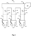
- an exemplary exhaust ventilation system 100 including an exhaust hood 105 positioned above a plurality of cooking appliances 115 and provided in communication with an exhaust assembly 145 through an exhaust duct 110.
- a bottom opening of the exhaust hood 105 may be generally rectangular but can have any other desired shape. Walls of the hood 105 define an interior volume 185, which communicates with a downwardly facing bottom opening 190 at an end of the hood 105 that is positioned over the cooking appliances 115.
- the interior volume 185 can also communicate with the exhaust assembly 145 through the exhaust duct 110.
- the exhaust duct 110 can extend upwardly toward the outside venting environment through the exhaust assembly 145.
- Exhaust assembly 145 can include a motorized exhaust fan 130, by which the exhaust air generated by the cooking appliances 115 is drawn into the exhaust duct 110 and for expelling into the outside venting environment.
- a motorized exhaust fan 130 by which the exhaust air generated by the cooking appliances 115 is drawn into the exhaust duct 110 and for expelling into the outside venting environment.
- an exhaust air flow path 165 is established between the cooking appliances 115 and the outside venting environment.
- fumes, air pollutants and other air particles are exhausted into the outside venting environment through the exhaust duct 110 and exhaust assembly 145.
- the exhaust ventilating system 100 can further include a control module 302 which preferably includes a programmable processor 304 that is operably coupled to, and receives data from, a plurality of sensors and is configured to control the speed of the motorized exhaust fan 130, which in turn regulates the exhaust air flow rate in the system 100.
- the control module 302 controls the exhaust fan 130 speed based on the output of a temperature sensor 125 positioned on or in the interior of the exhaust duct 110, and the output of infrared (IR) radiant temperature sensors 120, each positioned to face the surface of the cooking appliances 115.
- IR infrared
- three IR sensors 120 can be provided, each one positioned above a respective cooking appliance 115, so that each IR sensor 312 faces a respective cooking surface 115.
- any number and type of IR sensors 120 and any number of cooking appliances 115 may be used, as long as the radiant temperature of each cooking surface is detected.
- the control module 302 communicates with sensors 125 and 120 and identifies the cooking appliance status based on the sensor readings.
- the status of the cooking appliances 115 is determined based on the exhaust air temperature and the radiant temperature sensed using these multiple detectors.
- the control module 302 communicates with the motorized exhaust fan 130 which includes a speed control module such as a variable frequency drive (VFD) to control the speed of the motor, as well as one or more motorized balancing dampers (BD) 150 positioned near the exhaust duct 110.
- the control module 302 can determine a cooking appliance status (AS) based on the exhaust temperature sensor 125 and the IR radiant temperature sensor 120 outputs, and change the exhaust fan 130 speed as well as the position of the motorized balancing dampers 150 in response to the determined cooking appliance status (AS).
- the status of a cooking appliance 115 can be determined based on temperature detected by the exhaust temperature sensors 125 and the IR sensors 120. According to various embodiments, the method by which the appliance status (AS) is determined is shown in Figures 4-12 and discussed in detail below. Based on the determined appliance status (AS), the control module 302 selects a fan speed and/or a balancing damper position in the system so that the exhaust flow rate corresponds to a pre-determined exhaust flow rate associated with a particular appliance status (AS).
- AS appliance status
- a second embodiment of an exhaust ventilation system 200 having a plurality of exhaust hoods 105' which can be positioned above one or more cooking appliances 115 (depending on the size of the cooking equipment).
- the system 200 can include at least one exhaust temperature sensor 125 for each of the respective hoods 105', as well as at least one pressure transducer 155 connected to each of the respective hood tab ports (TAB).
- Each of the exhaust hood ducts 110 can include a motorized balancing damper 150.
- the balancing dampers 150 can be positioned at the respective hood ducts 110 and may include an actuator that provides damper position feedback.
- the system 200 can also include at least one IR sensor 312 positioned so that it detects the radiant temperature of respective cooking surfaces.
- An exhaust fan 130 can be connected to the exhaust assembly 145 to allow exhaust air to be moved away from the cook-tops into the surrounding outside venting environment.
- An additional pressure transducer 140 can be included to measure the static pressure in the main exhaust duct that is part of the exhaust assembly 145, as well as a plurality of grease removing filters 170 at the exhaust hood 105 bottom opening 190 to remove grease and fume particles from entering the hood ducts 110.
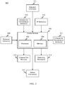
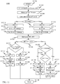
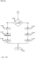
- FIG. 3 shows a schematic block diagram of an exhaust flow rate control system 300 that can be used in connection with any of the above shown systems (e.g., 100 and 200).
- the exhaust flow control system 300 includes a control module 302.
- the control module 302 includes a processor 304 and a memory 306.
- the control module 302 is coupled to and receives inputs from a plurality of sensors and devices, including an IR sensor 312, which can be positioned on the exhaust hood canopy 105 so that the IR sensor 312 faces the surface of the cooking appliance 115 and detects the radiant temperature emanating from the cooking surface, an exhaust air temperature sensor 125 installed close to a hood duct 110 to detect the temperature of the exhaust air that is sucked into the hood duct 110, an ambient air temperature sensor 160 positioned near the ventilation system (100, 200) to detect the temperature of the air surrounding the cooking appliance 115, a pressure sensor 155, which can be positioned near a hood tab port (TAB) to detect the pressure built-up in the hood duct 110, and optional operator controls 311.
- a IR sensor 312 which can be positioned on the exhaust hood canopy 105 so that the IR sensor 312 faces the surface of the cooking appliance 115 and detects the radiant temperature emanating from the cooking surface
- an exhaust air temperature sensor 125 installed close to a hood
- Inputs from the sensors 308-314 and operator controls 311 are transferred to the control module 302, which then processes the input signals and determines the appliance status (AS) or state.
- the control module processor 304 can control the speed of the exhaust fan motor(s) 316 and/or the position of the motorized balancing dampers 318 (BD) based on the appliance state. Each cooking state is associated with a particular exhaust flow rate (Q), as discussed below.
- the control module 302 determines the state the is in, it can then adjust the speed of the exhaust fan 316 speed and the position of the balancing dampers 318 to achieve a pre-determined air flow rate associated with each appliance status.
- the sensors 308-314 can be operably coupled to the processor 304 using a conductive wire.
- the sensor outputs can be provided in the form of an analog signal (e.g. voltage, current, or the like).
- the sensors can be coupled to the processor 304 via a digital bus, in which case the sensor outputs can comprise one or more words of digital information.
- the number and positions of exhaust temperature sensors 314 and radiant temperature sensors (IR sensors) 312 can be varied depending on how many cooking appliances and associated hoods, hood collars and hood ducts are present in the system, as well as other variables such as the hood length.
- the number and positioning of ambient air temperature sensors 310 can also be varied as long as the temperature of the ambient air around the ventilation system is detected.
- the number and positioning of the pressure sensors 308 can also be varied as long as they are installed in the hood duct in close proximity to the exhaust fan 130 to measure the static pressure (Pst) in the main exhaust duct. All sensors are exemplary and therefore any known type of sensor may be used to fulfill the desired function.
- the control module 302 can be coupled to sensors 308-314 and the motors 316 and dampers 318 by any suitable wired or wireless link.
- control modules 302 can be provided.
- the type and number of control modules 302 and their location in the system may also vary depending on the complexity and scale of the system as to the number of above enumerated sensors and their locations within a system.
- control module 302 preferably contains a processor 304 and a memory 306, which can be configured to perform the control functions described herein.
- the memory 306 can store a list of appropriate input variables, process variables, process control set points as well as calibration set points for each hood. These stored variables can be used by the processor 304 during the different stages of the check, calibration, and start-up functions, as well as during operation of the system.
- the processor 304 can execute a sequence of programmed instructions stored on a computer readable medium (e.g., electronic memory, optical or magnetic storage, or the like). The instructions, when executed by the processor 304, cause the processor 304 to perform the functions described herein.
- the instructions may be stored in the memory 306, or they may be embodied in another processor readable medium, or a combination thereof.
- the processor 304 can be implemented using a microcontroller, computer, an Application Specific Integrated Circuit (ASIC), or discrete logic components, or a combination thereof.
- ASIC Application Specific Integrated Circuit
- the processor 304 can also be coupled to a status indicator or display device 317, such as, for example, a Liquid Crystal Display (LCD), for output of alarms and error codes and other messages to a user.
- a status indicator or display device 317 such as, for example, a Liquid Crystal Display (LCD), for output of alarms and error codes and other messages to a user.
- the indicator 317 can also include an audible indicator such as a buzzer, bell, alarm, or the like.
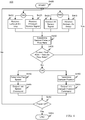
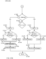
- the method 400 begins at S405 and continues to S410 or S425 to receive an exhaust air temperature input or a pressure sensor input and to S415 and S420 to receive an ambient air temperature input and an infrared sensor input. Control continues to S430.
- the current exhaust flow rate is compared to the desired exhaust flow rate. If the determined exhaust flow rate at S430 is the desired exhaust flow rate, control restarts. If the determined exhaust flow rate at S430 is not the desired exhaust flow rate, control proceeds to S440 or S450, based on system configuration (e.g., if motorized dampers are present then control proceed to S450, but if no motorized dampers are present then control proceeds to S440).
- the damper(s) position is determined at S450 or the exhaust fan speed is determined at S440.
- the control proceeds to output a damper position command to the damper(s) at S455 or an output speed command to the exhaust fan at S445.
- the control can proceed then to determine whether the power of the cooking appliance is off at S460, in which case the method 400 ends at S465, or to start the method again if power is determined to still be on at S460.
- the system 100, 200 can be checked and calibrated by the control module 302 during the starting process, in order to balance each hood to a preset design and idle exhaust flow rate, to clean and recalibrate the sensors, if necessary, and to evaluate each component in the system for possible malfunction or breakdown.
- the appropriate alarm signals can be displayed on an LCD display in case there is a malfunction in the system, to inform an operator of the malfunction and, optionally, how to recover from the malfunction.
- the control module 302 may include a list of the following examples of variables for each hood, as set forth below, in Tables 1-4: Table 1 Hood set point list (which can be preset) Parameter name & units Default value Notes Qdesign, cfm Kf Kidle 0.2 kFilterMissing 1.1 kFilterClogged 1.1 Patm, "Hg 29.92 Calculated for jobs with elevation above 1000 ft.
- dTcook °F 10 dTspace, °F 10 Tmax, °F 110 Tfire, °F 400 Set to be at least 10°F below fuse ling temperature TimeCook, s 420 TimeOR, s 60 dTIRmax, °F 5 Table 2 List of process control set points Parameter name & units Default value Notes IR1_Derivative_Max_SP -1°C/sec Derivative for Flare-up Set Point IR1_Derivative_Min_SP 300 sec Derivative for IR Index Drop Set Point IR1_Drop_SP1 1 °C IR Index Drop Set Point IR1_Filter_Time 10 sec IR Signal Filter Time Set Point IR1_Jump_SP 1 °C IR Signal Jump Set Point (for flare-up) IR1_Start_SP 30 °C IR Signal Start Cooking Equipment Set Point IR2_Cooking_Timer1 420 sec.
- control module 302 may include a list of the following example variables for each hood, as set forth below in Tables 5-8:
- Hood set point list (may be preset) Parameter name & units Default value Notes Qdesign, cfm Kf Kidle 0.2 kFilterMissing 1.1 kFilterClogged 1.1 Patm, "Hg 29.92 Calculated for jobs with elevation above 1000 ft.
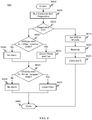
- FIG. 5 illustrates a flow diagram for a start-up routine 500 which can be performed by the control module 302 of an embodiment having single or multiple hoods connected to a single exhaust fan, and without motorized balancing dampers at the hood level.
- the start-up routine 500 starts at S502 and can include one of the following three options to start the exhaust fan 316:
- the control module 302 can analyze a second reading as well before the system operation is started: At block S530, the exhaust temperature (Tex) can be measured with an exhaust temperature sensor 125. If the exhaust temperature exceeds a minimum preset exhaust temperature (Tex min) (block S535), the control module 302 can start the fan and set the exhaust air flow (Q) at (Qidle) (block S545). If the exhaust temperature (Tex) does not exceed the minimum exhaust temperature (Tex min), the control module 302 can turn the fan off (block S550). The start-up routine can be terminated after these steps are followed (block S550).
- Pre-programmable e.g., for a week
- schedule to switch on and switch off exhaust hoods.
- exhaust airflow (Q) is set to (Qidle).
- actuating of an override button on the hood can set hood exhaust airflow (Q) to (Qdesign) for the preset period of time (TimeOR).
- the flow diagram for the start-up routine implemented by the control module 302 of a second embodiment of a system 200 with multiple hoods connected to a single exhaust fan, and with motorized balancing dampers at the hood level follows substantially the same steps as illustrated in FIG.5 , except that at each step the balancing dampers BD can be kept open so that together with the exhaust fan, the appropriate exhaust air flow (Q) can be maintained.
- a flow diagram is provided showing a routine 600 which can be performed by the control module 302 to check the system 100 before the start of the flow control operation.
- the routine 600 can start at S602 and continue to a control module self-diagnostics process (block S605). If the self-diagnostic process is OK (block S610) the control module 302 can set the variable frequency drive (VFD) which controls the exhaust fan speed to a preset frequency (VFDidle) (block S615). Then the static pressure can be measured by a pressure transducer positioned at the hood TAB port (block S620) and the exhaust flow can be set to (Q) calculated using the formula of Eq. 1 (block S625).
- VFD variable frequency drive
- VFDidle preset frequency
- control module 302 can verify whether the (VFD) is the preset (VFDidle) and whether the exhaust air flow (Q) is less or exceeds (Qidle) by a threshold airflow coefficient (blocks S630, S645). Based on the exhaust airflow reading, the control module 302 generates and outputs appropriate error codes, which can be shown or displayed on an LCD display or other appropriate indicator 317 attached to the exhaust hood or coupled to the control module 302.
- a flow diagram is provided showing another routine 700 which can be performed by the control module 302 to check the system 200.
- the routine 700 can start at S702 and continue to a control module 302 self-diagnostics process (block S705). If a result of the self-diagnostic process is OK (block S710), the control module 302 can maintain the exhaust air flow (Q) at (Qidle) by maintaining the balancing dampers in their original or current position (block S715). Then, the static pressure (dp) is measured by the pressure transducer positioned at the hood TAB port (block S720), and the exhaust flow is set to (Q) calculated using Eq. 1 (block S725). If the self-diagnostics process fails, the control module can set the balancing dampers (BD) at open position and (VFD) at (VFDdesign) (block S730).
- BD balancing dampers
- the control module 302 can then check whether the balancing dampers are malfunctioning (block S735). If there is a malfunctioning balancing damper, the control module 302 can open the balancing dampers (block S740). If there is no malfunctioning balancing damper, then the control module 302 can check whether there is a malfunctioning sensor in the system (block S745). If there is a malfunctioning sensor, the control module 302 can set the balancing dampers at (BDPdesign), the (VFD) at (VFDdesign) and the exhaust airflow to (Qdesign) (block S750). Otherwise, the control module 302 can set (VFD) to (VFDidle) until the cooking appliance is turned off (block S755). This step terminates the routine (block S760).
- the hood 105 is automatically calibrated to design airflow (Qdesign).
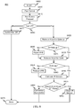
- the calibration procedure routine 800 is illustrated in FIG. 8 .
- the routine starts at S802 and can be activated with all ventilation systems functioning and cooking appliances in the off state (blocks S805, S810).
- the calibration routine 800 can commence with the fan turned off (blocks S810, S870). If the fan is turned off, the hood can be balanced to the design airflow (Qdesign) (block S830). If the hood is not balanced (block S825), the control module 302 can adjust VFD (block S830) until the exhaust flow reaches (Qdesign) (block S835).
- the routine 800 then waits until the system is stabilized. Then, the hood 105 can be balanced for (Qidle) by reducing (VFD) speed (blocks S840, S845). The routine 800 once again waits until the system 100 is stabilized.
- the next step is to calibrate the sensors (block S850).
- the calibration of the sensors can be done during a first-time calibration mode, and is performed for cold cooking appliances and when there are no people present under the hood.
- the radiant temperature (IRT) can be measured and compared to a thermostat reading (Tspace), and the difference can be stored in the control module 302 memory 306 for each of the sensors (block S855).
- Tspace thermostat reading
- the change in the radiant temperature is measured again and is compared to the calibrated value stored in the memory 306 (block S855). If the reading is higher than a maximum allowed difference, a warning is generated in the control module 302 to clean the sensors (block S860). Otherwise the sensors are considered calibrated (block S865) and the routine 800 is terminated (block S875).
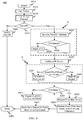
- FIG. 9 illustrates the calibration routine 900 for a system with multiple hoods, one fan and no motorized balancing dampers.
- the routine 900 can follow substantially the same steps as for a single hood, single fan, and no motorized damper system shown above, except that for routine 900 every hood is calibrated.
- the routine 900 starts with Hood 1 and follows hood balancing steps as shown above (blocks S905-S930, and S985), as well as sensor calibration steps as shown above (blocks S935-S950).
- the airflow for the next hood is verified (block S955). If the airflow is at set point (Qdesign), the sensor calibration is repeated for the second (and any subsequent) hood (blocks S960, S965). If the airflow is not at the set point (Qdesign), the airflow and the sensor calibration can be repeated (S970) for the current hood. The routine 900 can be followed until all hoods in the system are calibrated (S965). The new design airflows for all hoods can be stored in the memory 306 (block S975) and control ends at S980.
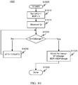
- FIG. 10 illustrates the automatic calibration routine 1000 which may be performed by the second embodiment 200.
- the calibration routine 1000 all hoods are calibrated to design airflow (Qdesign) at minimum static pressure.
- the calibration procedure 1000 can be activated during the time the cooking equipment is not planned to be used with all hood filters in place, and repeated regularly (once a week for example).
- the routine 1000 can be activated at block S1005.
- each hood can be balanced to achieve the design airflow (Qdesign) using the balancing dampers.
- Qdesign design airflow
- each BDP can be less than 1 (less than fully open). There may also be a waiting period in which the system stabilizes.
- FIG. 11 is a flow chart of a method 1100 to control the exhaust airflow as implemented in the various embodiments in accordance with the system 100.
- AS appliance status
- the control module 302 can change the exhaust airflow (Q) in the system 100 to correspond to a predetermined airflow (Qdesign), a measured airflow (Q) (see below), and a predetermined (Qidle) airflow.
- the control module 302 can adjust the airflow (Q) to correspond to the predetermined (Qdesign) airflow.
- control begins at S1102 and continues to block S1104, in which the appliance status can be determined based on the input received from the exhaust temperature sensors 125 and the IR temperature sensors 120.
- the exhaust temperature (Tex) and the ambient space temperature (Tspace) values can be read and stored in the memory 306 (block S1106) in order to calculate the exhaust airflow (Q) in the system (block S1108).
- the exhaust airflow (Q) can be calculated, for example, using equation Eq. 6.
- AS 1
- the operation 1100 may end at block S1158, with the control module 302 setting the airflow (Q) at the airflow level based on the determined appliance status (AS).
- FIGS. 12A-12C illustrate an exemplary method 1200 to control the exhaust airflow in a system 200 with motorized balancing dampers at each exhaust hood 105.
- FRT radiant temperature
- Tex exhaust temperature
- Tmin minimum value
- AS 1
- the operation may then end and the exhaust airflow is set according to the determined appliance status (block S1268).
- FIG. 13 is a block diagram of an exemplary exhaust flow control system in accordance with the present disclosure.
- a system 1300 includes a plurality of control modules (1302, 1308, and 1314) each coupled to respective ones of sensors (1304, 1310 and 1316, respectively), as described above (e.g., temperature, pressure, etc.), and outputs (1306, 1312, and 1318, respectively), as described above (e.g., motor control and damper control signals).
- the control modules can control their respective exhaust flow systems independently or in conjunction with each other. Further, the control modules can be in communication with each other.
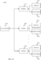
- FIG. 14 is a block diagram of an exemplary exhaust flow control system in accordance with the present disclosure.
- a system 1400 includes a single control module 1402 coupled to a plurality of interfaces 1404-1408, which are each in turn coupled to respective sensors (1410-1414) and control outputs (1416-1420).
- the control module 1402 can monitor and control the exhaust flow rate for multiple hoods adjacent to multiple appliances. Each appliance can be independently monitored and an appropriate exhaust flow rate can be set as described above.
- the single control module 1402 may reduce costs and simplify maintenance for the exhaust flow control systems and allow an existing system to be upgraded or retrofitted to include the exhaust flow control method described above.
- FIG. 15 is a block diagram of an exemplary exhaust flow control system in accordance with the present disclosure.
- a system 1500 includes a control module 1502 coupled to sensors 1504 and control outputs 1506.
- the control module 1502 is also coupled to an alarm interface 1508, a fire suppression interface 1512, and an appliance communication interface 1516.
- the alarm interface 1508 is coupled to an alarm system 1510.
- the fire suppression interface 1512 is coupled to a fire suppression system 1514.
- the appliance communication interface 1516 is coupled to one or more appliances 1518-1520.
- control module 1502 can communicate and exchange information with the alarm system 1510, fire suppression system 1514, and appliances 1518-1520 to better determine appliance states and a suitable exhaust flow rate. Also, the control module 1502 may provide information to the various systems (1510-1520) so that functions can be coordinated for a more effective operational environment. For example, the exhaust flow control module 1502, through its sensors 1504, may detect a fire or other dangerous condition and communicate this information to the alarm system 1510, the fire suppression system 1514, and the appliances 1518-1520 so that each device or system can take appropriate actions. Also, information from the appliances 1518-1520 can be used by the exhaust flow control system to more accurately determine appliance states and provide more accurate exhaust flow control.
Claims (12)
- Ein Verfahren des Steuerns eines Abluftstroms in einem Abluftventilationssystem (100), welches eine Ablufthaube (105) aufweist, wobei das Verfahren aufweist:Empfangen, an einem Steuermodul (302), eines Ablufttemperatursignals, welches eine Temperatur (Tex) von Abluft in einer Nähe der Ablufthaube (105, S410, S530) repräsentiert, wobei das Ablufttemperatursignal durch einen Ablufttemperatursensor (125) erzeugt wird,Empfangen, an dem Steuermodul (302), eines Strahlungstemperatursignals, welches eine Temperatur einer Fläche einer Kochvorrichtung (115) repräsentiert, die die Abluft erzeugt (S420, S505), wobei das Strahlungstemperatursignal durch einen Strahlungstemperatursensor (120) erzeugt wird,Ermitteln in dem Steuermodul (302) eines Zustands der Kochvorrichtung (115) basierend auf dem empfangenen Ablufttemperatursignal und dem empfangenen Strahlungstemperatursignal (S1112, S1118), wobei das Ermitteln weiter ein Ermitteln einer Fluktuation (FRT) in der Strahlungstemperatur (S1128) aufweist, undSteuern der Abluftstromrate (Q) in Antwort auf den ermittelten Vorrichtungszustand durch Ausgeben eines Steuersignals von dem Steuermodul (S1114, S1120),wobei der Kochvorrichtungszustand einen Kochzustand, einen Leerlaufzustand und einen Aus-Zustand aufweist,wobei für die Kochvorrichtung (115) ermittelt wird, dass sie sich im Kochzustand befindet, wenn die Fluktuation (FRT) in der Strahlungstemperatur ermittelt wird und eine mittlere Strahlungstemperatur (IRT) größer ist als eine vorbestimmte Minimalstrahlungstemperatur (IRTmin, S1132), für die Kochvorrichtung (115) ermittelt wird, dass sie sich im Leerlaufzustand befindet, wenn keine Fluktuation in der Strahlungstemperatur ermittelt wird (S1138), und für die Kochvorrichtung (115) ermittelt wird, dass sie sich im Aus-Zustand befindet, wenn keine Fluktuation in der Strahlungstemperatur ermittelt wird und die mittlere Strahlungstemperatur (IRT) geringer ist als eine vorbestimmte Minimalstrahlungstemperatur (IRTmin, S1146).
- Das Verfahren gemäß Anspruch 1, wobei das Steuern ein Ausgeben eines Signals aufweist, um die Abluftstromrate (Q) zwischen einer Entwurf-Abluftstromrate (Qdesign), einer Leerlauf-Abluftstromrate (Qidle) und einer Aus-Abluftstromrate basierend auf einer Änderung des Kochvorrichtungszustands zu ändern.
- Das Verfahren gemäß Anspruch 2, wobei das Steuermodul (302) die Abluftstromrate (Q) zur Entwurf-Abluftstromrate (Qdesign) ändert, wenn für die Kochvorrichtung ermittelt wird, dass sie sich im Kochzustand befindet (S1122), zur Leerlauf-Abluftstromrate (Qidle) ändert, wenn für den Vorrichtungszustand ermittelt wird, der Leerlaufzustand zu sein (S1144), und zur Aus-Abluftstromrate ändert, wenn für die Kochvorrichtung (115) ermittelt wird, dass sie sich im Aus-Zustand befindet (S1150).
- Das Verfahren gemäß Anspruch 3, wobei das Ändern ein Ändern einer Geschwindigkeit eines Abluftgebläses (130) basierend auf dem Vorrichtungszustand oder ein Betätigen einer Ausgleichsklappe (150) basierend auf dem Vorrichtungszustand aufweist.
- Das Verfahren gemäß Anspruch 1, weiter ein Messen einer Umgebungslufttemperatur in der Nähe des Ventilationssystems (100) aufweisend.
- Das Verfahren gemäß Anspruch 5, wobei das Ermitteln weiter ein Ermitteln einer Differenz zwischen der Ablufttemperatur (Tex) in der Nähe der Ablufthaube (105) und der Umgebungstemperatur in der Nähe des Ventilationssystems (100) aufweist.
- Das Verfahren gemäß Anspruch 6, wobei sich die Kochvorrichtung (115) im Kochzustand befindet, wenn die Ablufttemperatur (Tex) größer oder gleich einer vorbestimmten Maximalumgebungstemperatur ist, sich die Kochvorrichtung (115) im Leerlaufzustand befindet, wenn die Ablufttemperatur (Tex) geringer ist als die vorbestimmte Maximalumgebungstemperatur, und sich die Kochvorrichtung (115) im Aus-Zustand befindet, wenn die Ablufttemperatur (Tex) geringer ist als eine vorbestimmte Umgebungstemperatur.
- Das Verfahren gemäß Anspruch 1, wobei die Strahlungstemperatur unter Verwendung eines Infrarotsensors (120) gemessen wird.
- Das Verfahren gemäß Anspruch 1, wobei die Ablufttemperatur (Tex) und die Umgebungstemperatur in der Nähe des Ventilationssystems (100) unter Verwendung eines jeweiligen Temperatursensors (125, 160) gemessen werden.
- Das Verfahren gemäß Anspruch 1, weiter aufweisend:Kalibrieren des Abluftventilationssystems (100) vor dem besagten Steuern des Abluftstroms (800, 900, 1000).
- Ein Abluftventilationssystem (100), welches eine Ablufthaube (105) aufweist, zur Verwendung mit einer Kochvorrichtung (115), aufweisend:einen Ablufttemperatursensor (125) zum Erzeugen eines Ablufttemperatursignals, welches eine Temperatur (Tex) einer Abluft in der Nähe der Ablufthaube (105) repräsentiert,einen Strahlungstemperatursensor (120) zum Erzeugen eines Strahlungstemperatursignals, welches eine Temperatur einer Fläche der Kochvorrichtung (115) repräsentiert, welche die Abluft erzeugt,ein Steuermodul (302), welches eingerichtet ist, um das Ablufttemperatursignal und das Strahlungstemperatursignal zu empfangen, um einen Zustand der Kochvorrichtung (115) basierend auf dem empfangenen Ablufttemperatursignal und dem empfangenen Strahlungstemperatursignal zu ermitteln, und um die Abluftstromrate (Q) in Antwort auf den ermittelten Vorrichtungszustand durch Ausgeben eines Steuersignals von dem Steuermodul (302) zu steuern, und um eine Fluktuation (FRT) in der Strahlungstemperatur zu ermitteln,ein Abluftgebläse (130) zum Entfernen von Abluft, welche durch die Kochvorrichtung (115) erzeugt wird, undeine Motorsteuerungsvorrichtung, welche mit dem Steuermodul (302) und dem Abluftgebläse (130) gekuppelt ist,wobei das Ermitteln des Zustands der Kochvorrichtung (115) auf der Fluktuation (FRT) der Strahlungstemperatur basiert,wobei der Zustand der Kochvorrichtung (115) einen Kochzustand, einen Leerlaufzustand und einen Aus-Zustand aufweist, undwobei das Steuermodul (302) eingerichtet ist, um für die Kochvorrichtung(115) zu ermitteln, dass sie sich im Kochzustand befindet, wenn eine Fluktuation (FRT) in der Strahlungstemperatur ermittelt wird und die mittlere Strahlungstemperatur (IRT) größer ist als eine vorbestimmte Minimalstrahlungstemperatur (IRTmin), dass sie sich im Leerlaufzustand befindet, wenn keine Fluktuation in der Strahlungstemperatur ermittelt wird, und dass sie sich im Aus-Zustand befindet, wenn keine Fluktuation in der Strahlungstemperatur ermittelt wird und die mittlere Strahlungstemperatur (IRT) geringer ist als eine vorbestimmte Minimalstrahlungstemperatur (IRTmin).
- Das System (100) gemäß Anspruch 11, weiter einen Temperatursensor (160) zum Messen einer Umgebungstemperatur der Luft in der Nähe des Ventilationssystems (100) und zumindest eine motorisierte Ausgleichsklappe (150) aufweisend, welche an der Ablufthaube (105) angebracht ist, um ein Volumen der Abluft zu steuern, welche in die Ablufthaube (105) eintritt, wobei das Steuermodul (302) die Abluftstromrate durch Steuern einer Geschwindigkeit des Abluftgebläses (130) und/oder einer Position der zumindest einen motorisierten Ausgleichsklappe (318) steuert.
Priority Applications (1)
| Application Number | Priority Date | Filing Date | Title |
|---|---|---|---|
| PL09831153T PL2370744T3 (pl) | 2008-12-03 | 2009-12-03 | System i sposób sterowania natężeniem przepływu spalin |
Applications Claiming Priority (3)
| Application Number | Priority Date | Filing Date | Title |
|---|---|---|---|
| US11971608P | 2008-12-03 | 2008-12-03 | |
| US18516809P | 2009-06-08 | 2009-06-08 | |
| PCT/US2009/066660 WO2010065793A1 (en) | 2008-12-03 | 2009-12-03 | Exhaust flow control system and method |
Publications (3)
| Publication Number | Publication Date |
|---|---|
| EP2370744A1 EP2370744A1 (de) | 2011-10-05 |
| EP2370744A4 EP2370744A4 (de) | 2012-11-28 |
| EP2370744B1 true EP2370744B1 (de) | 2019-02-20 |
Family
ID=42233620
Family Applications (1)
| Application Number | Title | Priority Date | Filing Date |
|---|---|---|---|
| EP09831153.3A Active EP2370744B1 (de) | 2008-12-03 | 2009-12-03 | System und steuerungsverfahren zur dunstabführung |
Country Status (15)
| Country | Link |
|---|---|
| US (3) | US9494324B2 (de) |
| EP (1) | EP2370744B1 (de) |
| JP (3) | JP5767974B2 (de) |
| CN (2) | CN102301187A (de) |
| AU (2) | AU2009322238C1 (de) |
| BR (1) | BRPI0917043B1 (de) |
| CA (1) | CA2745432C (de) |
| DK (1) | DK2370744T3 (de) |
| HK (1) | HK1224359A1 (de) |
| MX (1) | MX2011005770A (de) |
| PL (1) | PL2370744T3 (de) |
| RU (1) | RU2524104C2 (de) |
| SG (1) | SG171458A1 (de) |
| WO (1) | WO2010065793A1 (de) |
| ZA (1) | ZA201103916B (de) |
Families Citing this family (72)
| Publication number | Priority date | Publication date | Assignee | Title |
|---|---|---|---|---|
| JP5105376B2 (ja) * | 2006-04-18 | 2012-12-26 | オーワイ ハルトン グループ リミテッド | 熱エネルギの搬送方法 |
| US20090061752A1 (en) | 2007-08-28 | 2009-03-05 | Current Energy Controls, Lp | Autonomous Ventilation System |
| EP2407946B1 (de) | 2010-07-15 | 2012-09-05 | Siemens Schweiz AG | Erkennen von Verstopfungen und Unterbrüchen bei einem Ansaug-rauchmelder (ASD) |
| US20120055275A1 (en) * | 2010-09-02 | 2012-03-08 | Streivor Air Systems, Inc. | System and Method for Smart Operation of an Exhaust Hood Using a Protected Monitoring Device |
| CA2754277A1 (en) * | 2010-10-01 | 2012-04-01 | Broan-Nutone Llc | Fluid cleaning system and method |
| JP5899393B2 (ja) * | 2011-02-25 | 2016-04-06 | パナソニックIpマネジメント株式会社 | レンジフード |
| JP2012220096A (ja) * | 2011-04-08 | 2012-11-12 | Panasonic Corp | レンジフードファン |
| US9909765B2 (en) | 2011-07-07 | 2018-03-06 | Oy Halton Group Ltd. | Exhaust hood methods, devices, and systems |
| WO2013038194A1 (en) * | 2011-09-13 | 2013-03-21 | Sirius Products Limited | An air extraction system |
| CN102393036A (zh) * | 2011-09-24 | 2012-03-28 | 广东工业大学 | 一种设有传感器的吸油烟机的安装结构 |
| US9109805B2 (en) * | 2012-01-19 | 2015-08-18 | General Electric Company | Range hood with temperature detection and notification |
| ITTO20120341A1 (it) * | 2012-04-17 | 2013-10-18 | Indesit Co Spa | Cappa con controllo di installazione e metodo per la sua attuazione |
| BR112014030580B1 (pt) | 2012-06-07 | 2020-12-01 | Oy Halton Group Ltd | método e sistema de detecção de uma condição em um sistema de ventilação de exaustão |
| CN102679505B (zh) * | 2012-06-13 | 2014-04-23 | 重庆大学 | 房间温度控制方法 |
| SE537339C2 (sv) * | 2012-06-25 | 2015-04-07 | Medicvent Ab | Ett centralflödessystem |
| US20140017989A1 (en) * | 2012-07-16 | 2014-01-16 | Solar Turbines Inc. | Power system enclosure |
| US9605860B2 (en) * | 2012-11-02 | 2017-03-28 | Flextronics Ap, Llc | Energy saving-exhaust control and auto shut off system |
| DE102012024975A1 (de) * | 2012-12-20 | 2014-06-26 | Diehl Ako Stiftung & Co. Kg | Dunstabzugshaube und Verfahren zum Steuern des Betriebs einer Dunstabzugshaube |
| DE102013204137A1 (de) * | 2013-03-11 | 2014-09-11 | BSH Bosch und Siemens Hausgeräte GmbH | Verfahren zum Ermitteln eines Betriebszustands einer Dunstabzugshaubenanordnung |
| AU2014239170B2 (en) * | 2013-03-15 | 2018-04-05 | Oy Halton Group Ltd. | Water spray fume cleansing with demand-based operation |
| WO2015071898A1 (en) * | 2013-11-18 | 2015-05-21 | Aps Technologies (Hong Kong) Limited | Kitchen hood device |
| US9702566B2 (en) | 2014-01-28 | 2017-07-11 | Illinois Tool Works Inc. | Cooking exhaust hood ventilation system and related methods |
| FI20145134L (fi) * | 2014-02-12 | 2015-08-13 | SeaKing Oy | Huuva |
| US20150302569A1 (en) * | 2014-04-22 | 2015-10-22 | General Electric Company | Sensing system for a cooktop appliance with airflow protected sensor |
| DK201400139U3 (da) * | 2014-10-07 | 2016-01-22 | Thermex Scandinavia As | Udsugningssystem |
| CN107110530B (zh) * | 2014-12-24 | 2020-01-17 | 皇家飞利浦有限公司 | 监测空气质量和可能影响空气质量的事件并采取补救行动的系统和方法 |
| US10434345B2 (en) * | 2015-02-18 | 2019-10-08 | Tyco Fire Products Lp | Fire protection systems and methods for ventilation hoods |
| FI128643B (fi) * | 2015-03-16 | 2020-09-30 | Air D Fin Oy | Älykäs ilmanvaihtojärjestelmä |
| CN104819500B (zh) * | 2015-05-18 | 2017-05-03 | 广东美的厨房电器制造有限公司 | 吸油烟机及其气体流量检测方法、装置、风速控制方法 |
| CN107835963B (zh) * | 2015-07-06 | 2021-10-08 | 皇家飞利浦有限公司 | 空气处理系统和方法 |
| US10399028B2 (en) | 2015-08-14 | 2019-09-03 | Tyco Fire Products Lp | Filter clogging monitoring systems and methods |
| KR101624607B1 (ko) * | 2015-09-22 | 2016-05-27 | 주식회사 인솔엔지니어링 | 주방 환기 제어 시스템 및 제어 방법 |
| DE102015122618A1 (de) * | 2015-12-22 | 2017-06-22 | Frima International Ag | System mit Gargerät und raumlufttechnischer Anlage sowie Verfahren zur Steuerung eines solchen Systems |
| GB2547678A (en) * | 2016-02-25 | 2017-08-30 | Johnson Electric Sa | Method of maintaining a position of an airflow-direction control element of a HVAC system |
| JP6656054B2 (ja) * | 2016-03-31 | 2020-03-04 | 大阪瓦斯株式会社 | 換気装置、及び算出方法 |
| IT201600092209A1 (it) * | 2016-09-13 | 2018-03-13 | P G A Srl | Sistema per automatizzare l'accensione, la regolazione e/o lo spegnimento di uno o piu' accessori per piani cottura o simili |
| FI128693B (fi) * | 2016-11-08 | 2020-10-15 | Climecon Oy | Ilmanvaihtojärjestelmän kokoonpanon tunnistusmenetelmä |
| CN108253474B (zh) * | 2016-12-29 | 2023-10-20 | 宁波方太厨具有限公司 | 一种智能吸油烟机及其控制方法 |
| EP4174813A3 (de) | 2017-03-20 | 2023-07-05 | Oy Halton Group Ltd. | Verfahren und systeme für brandschutzvorrichtungen |
| US10458669B2 (en) | 2017-03-29 | 2019-10-29 | Johnson Controls Technology Company | Thermostat with interactive installation features |
| CN110506184B (zh) * | 2017-03-31 | 2021-07-06 | 松下知识产权经营株式会社 | 换气系统、热交换型换气装置 |
| WO2018191703A1 (en) | 2017-04-14 | 2018-10-18 | Johnson Controls Technology Company | Thermostat with preemptive heating, cooling, and ventilation in response to elevated occupancy detection via proxy |
| WO2018191699A1 (en) | 2017-04-14 | 2018-10-18 | Johnson Controls Technology Company | Multi-function thermostat with intelligent supply fan control for maximizing air quality and optimizing energy usage |
| WO2018191716A1 (en) | 2017-04-14 | 2018-10-18 | Johnson Controls Technology Company | Multi-function thermostat with intelligent ventilator control for frost/mold protection and air quality control |
| US10712038B2 (en) | 2017-04-14 | 2020-07-14 | Johnson Controls Technology Company | Multi-function thermostat with air quality display |
| US10731885B2 (en) | 2017-04-14 | 2020-08-04 | Johnson Controls Technology Company | Thermostat with occupancy detection via proxy measurements of a proxy sensor |
| US11162698B2 (en) | 2017-04-14 | 2021-11-02 | Johnson Controls Tyco IP Holdings LLP | Thermostat with exhaust fan control for air quality and humidity control |
| CN110546485B (zh) * | 2017-04-17 | 2022-03-08 | 株式会社岛津制作所 | 发光分光分析装置 |
| CN107991433B (zh) * | 2017-11-09 | 2021-07-06 | 广州视源电子科技股份有限公司 | 烟雾值处理方法、系统、可读存储介质及烟雾处理设备 |
| CN107781886B (zh) * | 2017-11-27 | 2019-07-19 | 杨肇 | 一种零和式低碳油烟净化器及净化系统 |
| US11131474B2 (en) | 2018-03-09 | 2021-09-28 | Johnson Controls Tyco IP Holdings LLP | Thermostat with user interface features |
| CN110513812A (zh) * | 2018-05-22 | 2019-11-29 | 广州松下空调器有限公司 | 一种空调控制方法及空调器 |
| KR102037833B1 (ko) * | 2018-05-25 | 2019-10-29 | 린나이코리아 주식회사 | 주방용 승강식 레인지후드 제어 장치 및 방법 |
| US10788222B2 (en) * | 2018-08-03 | 2020-09-29 | Haier Us Appliance Solutions, Inc. | Cooking exhaust systems having one or more airflow features |
| US10627118B2 (en) * | 2018-08-03 | 2020-04-21 | Haier Us Appliance Solutions, Inc. | Cooking engagement system equipped with humidity sensor |
| KR102002078B1 (ko) * | 2018-11-13 | 2019-07-24 | 주식회사 제이텍 | 공조 설정조건에 따라 급배기 풍량을 조절하는 주방후드 시스템 및 그 제어방법 |
| WO2020112981A1 (en) * | 2018-11-29 | 2020-06-04 | Broan-Nutone Llc | Smart indoor air venting system |
| US11796187B2 (en) * | 2018-12-10 | 2023-10-24 | Midea Group Co., Ltd. | Electronically controlled vent damper |
| JP7365681B2 (ja) * | 2019-02-14 | 2023-10-20 | 富士工業株式会社 | レンジフード |
| US10989416B2 (en) | 2019-03-11 | 2021-04-27 | Spring Air Systems Inc. | Damper for kitchen exhaust hood |
| IT201900003805A1 (it) * | 2019-03-15 | 2020-09-15 | Rational Ag | Procedimento per il controllo di un dispositivo di cottura, dispositivo di cottura e sistema di cucina |
| JP2022526151A (ja) | 2019-04-04 | 2022-05-23 | オーワイ ハルトン グループ リミテッド | スライド式レンジフード |
| KR102266306B1 (ko) * | 2019-07-09 | 2021-06-16 | 심창섭 | 팬 분리형 렌지후드를 이용한 세대환기시스템 |
| US11835250B2 (en) * | 2020-01-09 | 2023-12-05 | Carrier Corporation | Method and a system for performing calibration of variable air volume (VAV) units |
| CN111412506B (zh) * | 2020-03-31 | 2022-04-15 | 佛山市顺德区美的洗涤电器制造有限公司 | 烹饪设备的开启检测方法及装置、吸油烟机和存储介质 |
| US11859848B2 (en) * | 2020-06-30 | 2024-01-02 | Johnson Controls Tyco IP Holdings LLP | Building control system using a control device position as a proxy for static pressure in a conduit |
| CN112178720B (zh) * | 2020-09-18 | 2022-11-04 | 华帝股份有限公司 | 一种集排烟机的控制方法及应用其的集排烟系统 |
| EP4043799B1 (de) * | 2021-02-16 | 2024-04-10 | Electrolux Appliances Aktiebolag | Dunstabzugshaube für ein kochfeld und verfahren zum betreiben einer dunstabzugshaube |
| CN113693433A (zh) * | 2021-08-12 | 2021-11-26 | 宁波方太厨具有限公司 | 蒸箱的排气控制方法、蒸箱及计算机可读存储介质 |
| EP4276364A1 (de) * | 2022-05-13 | 2023-11-15 | Arçelik Anonim Sirketi | Dunstabzugshaube mit verbesserter automatischer betriebsleistung |
| EP4276363A1 (de) * | 2022-05-13 | 2023-11-15 | Arçelik Anonim Sirketi | Dunstabzugshaube mit verbesserter automatischer betriebsleistung |
| CN117410995B (zh) * | 2023-12-04 | 2024-04-02 | 河南柏科沃电子科技有限公司 | 一种自适应调节型有源电力滤波器 |
Citations (1)
| Publication number | Priority date | Publication date | Assignee | Title |
|---|---|---|---|---|
| US20080274683A1 (en) * | 2007-05-04 | 2008-11-06 | Current Energy Controls, Lp | Autonomous Ventilation System |
Family Cites Families (258)
| Publication number | Priority date | Publication date | Assignee | Title |
|---|---|---|---|---|
| DE314477C (de) | 1900-01-01 | |||
| US2833615A (en) | 1952-10-03 | 1958-05-06 | Houdry Process Corp | Abatement of smog in flue gases |
| US2853367A (en) | 1954-02-10 | 1958-09-23 | Oxy Catalyst Inc | Cartridge type catalytic exhaust cleaner |
| US2743529A (en) | 1954-07-06 | 1956-05-01 | Oxy Catalyst Inc | Drying oven and operation thereof |
| US2862095A (en) | 1954-10-07 | 1958-11-25 | Philco Corp | Vapor treating means |
| CH334686A (de) | 1955-09-12 | 1958-12-15 | Ingenieurbureau W Hausammann & | Veränderbare Düse, insbesondere Lavaldüse für Windkanäle |
| US2933080A (en) | 1956-03-07 | 1960-04-19 | Oxy Catalyst Inc | Cooking apparatus |
| JPS4113143Y1 (de) | 1964-04-02 | 1966-06-22 | ||
| FR1418065A (fr) | 1964-07-16 | 1965-11-19 | Loire Atel Forges | Procédé et dispositif pour la régulation du captage des gaz d'affinage à l'oxygène |
| US3381134A (en) | 1964-10-05 | 1968-04-30 | Philip C. Wolf | Mass flow indicating means including an interferometer system |
| US3254588A (en) | 1965-05-24 | 1966-06-07 | Truhan Andrew | Laboratory fume hood |
| US3323439A (en) | 1966-01-28 | 1967-06-06 | Weaver | Damper and fire control device for ventilators |
| US3400649A (en) | 1967-01-26 | 1968-09-10 | Donald D. Jensen | Ventilating system including fume removal means |
| US3457850A (en) | 1967-12-11 | 1969-07-29 | Elster S Air Conditioning | Air curtain ventilator |
| US3536457A (en) | 1968-02-21 | 1970-10-27 | Gen Electric | Catalytic oxidation unit for domestic oven exhaust |
| SE339300B (de) | 1968-05-14 | 1971-10-04 | Electrolux Ab | |
| US3513766A (en) | 1968-06-24 | 1970-05-26 | Willard K Ahlrich | Ventilating hood |
| FR2030532A5 (de) | 1969-07-03 | 1970-11-13 | Snecma | |
| JPS5248645Y1 (de) | 1969-11-11 | 1977-11-05 | ||
| US3690245A (en) | 1970-09-17 | 1972-09-12 | Panacon Corp | Range hood unit with fire safeguard fan control system |
| US3752056A (en) | 1970-11-04 | 1973-08-14 | Sheldon And Co E | Laboratory exhaust hood |
| GB1377831A (en) | 1972-04-17 | 1974-12-18 | Secr Defence | Interferometers for fluid flow measurements |
| US3809480A (en) | 1972-07-24 | 1974-05-07 | Gen Dynamics Corp | Method and apparatus for surveying the velocities of a flow field |
| GB1450911A (en) | 1973-01-17 | 1976-09-29 | Nat Res Dev | Laser doppler velocimetry |
| US3829285A (en) | 1973-02-28 | 1974-08-13 | Mc Quay Perfex Inc | Recuperators for incinerators |
| US3952640A (en) | 1973-03-01 | 1976-04-27 | Vent-Cair, Inc. | Apparatus and method for extracting grease and smoke, and method of installing the same |
| US3895569A (en) | 1973-09-26 | 1975-07-22 | Ind Clean Air Inc | Air modulating fume system |
| US3943836A (en) | 1974-08-15 | 1976-03-16 | Vent-Cair, Inc. | Apparatus for removing fumes from the space above a cooking appliance in a restaurant |
| US4056877A (en) | 1974-09-26 | 1977-11-08 | Vent-Cair, Inc. | Method of installing apparatus for extracting grease and smoke |
| CA1081030A (en) | 1974-09-26 | 1980-07-08 | Irvin R. Kuechler | Method of installing kitchen grease hood |
| CA1069749A (en) | 1975-02-24 | 1980-01-15 | Econovent Systems | Ventilating apparatus |
| US3978777A (en) | 1975-02-24 | 1976-09-07 | Nett Louis A | Ventilating apparatus |
| US4047519A (en) | 1975-02-24 | 1977-09-13 | Nett Louis A | Ventilating apparatus |
| DE2518750B2 (de) * | 1975-04-26 | 1979-06-28 | E.G.O. Regeltechnik Gmbh, 7519 Oberderdingen | Dunstabzugshaube über Kochherden o.dgl |
| DE2640684C2 (de) | 1975-09-11 | 1981-11-26 | Matsushita Electric Industrial Co., Ltd., Kadoma, Osaka | Brat- bzw. Kochofen |
| US4147502A (en) | 1975-09-15 | 1979-04-03 | Roper Corporation | System for control of thermal potential |
| US4043319A (en) | 1975-09-18 | 1977-08-23 | Jensen Donald D | Exhaust hood |
| US4085736A (en) | 1975-10-01 | 1978-04-25 | Vent-Cair, Inc. | Grease-hood apparatus |
| JPS5248645A (en) | 1975-10-14 | 1977-04-18 | Kuraray Co Ltd | Process for preparation of cyclic terpene derivatives having carbonyl group |
| US4050368A (en) | 1976-01-02 | 1977-09-27 | Marion L. Eakes Co. | Exhaust system for industrial processes |
| US4117833A (en) | 1977-02-16 | 1978-10-03 | Mueller Robert H | Exhaust hood with adjustable air injection nozzle |
| US4134394A (en) | 1977-02-24 | 1979-01-16 | Otenbaker James T | Air ventilation system |
| US4105015A (en) | 1977-03-09 | 1978-08-08 | William C. Isom | Exhaust hood energy saving device |
| US4109641A (en) | 1977-05-25 | 1978-08-29 | Air Master Systems, Inc. | Adapter manifold for ventilation hood |
| US4146017A (en) | 1977-08-08 | 1979-03-27 | Overton Jr Duncan E | Hood system for cooking equipment |
| US4155348A (en) | 1977-10-11 | 1979-05-22 | Ahlrich Wilard K | Ventilating apparatus |
| US4213947A (en) | 1977-10-13 | 1980-07-22 | Champion International Corporation | Emission control system and method |
| US4160407A (en) | 1977-11-18 | 1979-07-10 | Bell Telephone Laboratories, Incorporated | Ventilating system |
| US4153044A (en) | 1978-01-23 | 1979-05-08 | Nett Louis A | Backshelf ventilating hood |
| US4138220A (en) | 1978-02-13 | 1979-02-06 | Colonial Metals, Inc. | Apparatus for catalytic oxidation of grease and fats in low temperature fumes |
| US4211154A (en) | 1978-09-20 | 1980-07-08 | Eakes Marion L | Apparatus for improving the collection of gases into a suction orifice |
| US4475534A (en) | 1978-11-30 | 1984-10-09 | Moriarty Daniel J | Ventilating system for kitchen stove |
| US4286572A (en) | 1979-03-08 | 1981-09-01 | Cambridge Engineering, Inc. | Ventilating hood |
| US4285390A (en) | 1979-04-16 | 1981-08-25 | Stainless Equipment Company | Method of and apparatus for supplying treated air to spaces having different cooling requirements |
| SE419830B (sv) | 1979-05-21 | 1981-08-31 | Leif Ingemar Lind | Sett och anordning for utsugning av fororenad luft |
| GB2054143B (en) | 1979-07-11 | 1983-06-29 | Atomic Energy Authority Uk | Measurement of the size of particles dispersed in a fluid |
| US4287405A (en) | 1979-10-02 | 1981-09-01 | Mitsubishi Jukogyo Kabushiki Kaisha | Process and apparatus for exhausting fumes produced by arc welding |
| US4373507A (en) | 1980-10-09 | 1983-02-15 | Jamestown Group | Stove construction |
| US4346692A (en) | 1980-11-26 | 1982-08-31 | Mccauley Lewis C | Make-up air device for range hood |
| US4350166A (en) | 1980-12-12 | 1982-09-21 | Honeywell Inc. | Apnea detector |
| US4467782A (en) | 1981-08-19 | 1984-08-28 | Russell Robert E | Ventilating system for use with devices which produce airborne impurities |
| US4398415A (en) | 1981-12-10 | 1983-08-16 | The United States Of America As Represented By The Secretary Of The Air Force | Swing link flexible wind tunnel nozzle |
| US4497242A (en) | 1982-02-11 | 1985-02-05 | Barber-Colman Company | Ventilation control system |
| GB2132335A (en) | 1982-12-21 | 1984-07-04 | Chung Tsung Cheng | Apparatus for exhausting gaseous emissions during cooking |
| SE8305034L (sv) | 1983-09-19 | 1985-03-20 | Bahco Ventilation Ab | Utsugningsanordning |
| US4484563A (en) | 1983-10-11 | 1984-11-27 | Alco Foodservice Equipment Company | Air ventilation and pollution cleaning system |
| US4483316A (en) | 1983-10-11 | 1984-11-20 | Alco Foodservice Equipment Company | Air ventilation system |
| US4528898A (en) | 1984-03-05 | 1985-07-16 | Imec Corporation | Fume hood controller |
| FI77163C (fi) | 1984-03-09 | 1989-02-10 | Halton Oy | Luftrenare. |
| JPS60213753A (ja) | 1984-04-09 | 1985-10-26 | Matsushita Seiko Co Ltd | クリ−ンベンチ |
| US4556046A (en) | 1984-04-12 | 1985-12-03 | Pizza Hut, Inc. | Hood for oven in pizza delivery vehicle |
| US4586486A (en) | 1984-07-06 | 1986-05-06 | National Air Systems, Inc. | Multilevel air distribution panel for air ventilation hood |
| FI71831C (fi) | 1985-04-12 | 1987-02-09 | Halton Oy | Fraonluftsanordning. |
| US4617909A (en) | 1985-05-06 | 1986-10-21 | Molitor Victor D | Method of and device for preventing smoke curling from underneath the hood of a grease extraction ventilator |
| US4823015A (en) | 1985-05-08 | 1989-04-18 | Adt, Inc. | Electrical interference free projected beam smoke detector |
| DE3519189A1 (de) | 1985-05-29 | 1986-12-04 | Buderus Ag, 6330 Wetzlar | Dunstabzugshaube |
| US4781460A (en) | 1986-01-08 | 1988-11-01 | Coulter Electronics Of New England, Inc. | System for measuring the size distribution of particles dispersed in a fluid |
| US4655194A (en) | 1986-04-15 | 1987-04-07 | Heat Transfer Specialties, Inc. | System for removing fumes |
| JPS6391442A (ja) | 1986-10-06 | 1988-04-22 | Aruku Kk | ガスレンジから発生する煙等の換気方法 |
| DE3639929A1 (de) | 1986-11-22 | 1988-06-01 | Babcock Bsh Ag | Durchlauftrockner fuer furnierblaetter |
| US4773311A (en) | 1986-11-24 | 1988-09-27 | Phoenix Controls Corporation | Make up air controller for use with fume hood systems |
| FI83696B (fi) | 1987-01-27 | 1991-04-30 | Halton Oy | Foerfarande foer reglering av ventilation. |
| JPH0788827B2 (ja) * | 1987-03-31 | 1995-09-27 | 三菱電機株式会社 | 送風機の運転制御装置 |
| JPS63251741A (ja) | 1987-04-08 | 1988-10-19 | Nagano Pref Gov Roudou Kijiyun Kyokai Rengokai | 流速勾配エアカ−テン装置 |
| DE3716257A1 (de) | 1987-05-15 | 1988-11-24 | Takeo Imai | Verfahren und vorrichtung zum auffangen verschmutzter substanzen |
| US4788905A (en) | 1987-06-10 | 1988-12-06 | Kohorn H Von | Combination cooking, eating and ventilating system |
| US4793715A (en) | 1987-08-28 | 1988-12-27 | Westinghouse Electric Corp. | Detector for aligning high power lasers |
| JPS6484039A (en) | 1987-09-24 | 1989-03-29 | Matsushita Electric Works Ltd | Smoke venting hood |
| US4921509A (en) | 1987-10-30 | 1990-05-01 | Micro-Technology Licensing Corporation | Air filtration system for ducted range hoods |
| US5033508A (en) | 1987-12-23 | 1991-07-23 | Coyne & Delany Co. | Sensor operated water flow control |
| AT390325B (de) | 1988-03-11 | 1990-04-25 | Tabarelli Werner | Interferometrische einrichtung zur messung von lageaenderungen eines beweglichen bauteiles |
| US5063834A (en) | 1988-06-10 | 1991-11-12 | Halton Oy | Focussed ventilation procedure and focussed ventilation means |
| JPH0233552A (ja) | 1988-07-21 | 1990-02-02 | Matsushita Seiko Co Ltd | レンジフード |
| CA1272064A (en) | 1988-08-19 | 1990-07-31 | Cameron Cote | Air canopy cooking system |
| US5251608A (en) | 1988-08-19 | 1993-10-12 | Cameron Cote | Air canopy ventilation system |
| US4903685A (en) | 1989-01-24 | 1990-02-27 | Melink Stephen K | Variable exhaust controller for commercial kitchens |
| US4934256A (en) | 1989-02-14 | 1990-06-19 | Labconco Corporation | Fume hood ventilation control system |
| DE3909125A1 (de) | 1989-03-20 | 1990-09-27 | Diehl Gmbh & Co | Steuereinrichtung einer dunstabzugshaube |
| JP2602326B2 (ja) | 1989-04-28 | 1997-04-23 | 株式会社日立製作所 | 自動換気装置 |
| US4944285A (en) * | 1989-05-25 | 1990-07-31 | Glassman Joseph T | Exhaust hood for pizza ovens |
| DE3918870C2 (de) | 1989-06-09 | 1995-06-29 | Roehl Hager Hannelore | Verfahren und Einrichtung zum Absaugen von Dämpfen und Dunststoffen |
| US4944283A (en) | 1989-08-29 | 1990-07-31 | Paloma Kogyo Kabushiki Kaisha | Gas burner |
| JPH0391616A (ja) * | 1989-09-05 | 1991-04-17 | Toshiba Corp | システムレンジフードファン |
| US4974579A (en) | 1989-09-28 | 1990-12-04 | Rheem Manufacturing Company | Induced draft, fuel-fired furnace apparatus having an improved, high efficiency heat exchanger |
| FI84096B (fi) | 1990-01-31 | 1991-06-28 | Halton Oy | Undertakskonstruktion och foerfarande foer att bringa luften att stroemma i samband med undertakskonstruktionen. |
| FI88433C (fi) | 1990-01-31 | 1994-08-17 | Halton Oy | Anordning foer ingaongs- och utgaongsluft och luftkonditioneringsfoerfarande |
| JPH03247937A (ja) | 1990-02-23 | 1991-11-06 | Mitsubishi Electric Corp | レンジフード |
| CH682512A5 (de) | 1990-03-02 | 1993-09-30 | Zurecon Ag | Dampfabzugeinrichtung. |
| US5147429A (en) | 1990-04-09 | 1992-09-15 | James Bartholomew | Mobile airborne air cleaning station |
| JP2654227B2 (ja) | 1990-04-13 | 1997-09-17 | 株式会社熊谷組 | 排気方法 |
| CH680834A5 (de) | 1990-06-19 | 1992-11-30 | Analyse Data Finance Sa | |
| JP2626189B2 (ja) | 1990-06-29 | 1997-07-02 | コクヨ株式会社 | 喫煙装置 |
| JP3134159B2 (ja) | 1990-07-05 | 2001-02-13 | 株式会社トルネックス | 人工竜巻発生機構及びその装置並びにこれを用いた照明装置 |
| JPH04113143A (ja) | 1990-08-31 | 1992-04-14 | Kansai Electric Power Co Inc:The | 厨房用レンジ装置 |
| US5090303A (en) | 1990-09-28 | 1992-02-25 | Landis & Gyr Powers, Inc. | Laboratory fume hood control apparatus having improved safety considerations |
| US5115728A (en) | 1990-09-28 | 1992-05-26 | Landis & Gyr Powers, Inc. | System for controlling the differential pressure of a room having laboratory fume hoods |
| US5092227B1 (en) | 1990-09-28 | 1995-02-14 | Landis & Gyr Powers Inc | Apparatus for controlling the ventilation of laboratory fume hoods |
| US5764579A (en) | 1990-10-01 | 1998-06-09 | American Auto-Matrix, Inc. | System for controlling laboratories with fume hoods |
| US5139009A (en) | 1990-10-11 | 1992-08-18 | Walsh Leo B | Exhaust ventilation control system |
| DK166229C (da) | 1990-11-02 | 1993-08-16 | Netavent As | Ventilationssystem |
| IT1244170B (it) | 1990-12-04 | 1994-07-08 | Cise Spa | Apparecchiatura laser per la misura della velocita' di un fluido. |
| DE4114329A1 (de) | 1991-05-02 | 1992-11-05 | Standard Elektrik Lorenz Ag | Dunstabzugshaube mit luftschleier |
| US5215497A (en) | 1991-07-10 | 1993-06-01 | Johnson Service Company | Fume hood controller |
| US5205783A (en) | 1991-08-22 | 1993-04-27 | Accu*Aire Systems, Inc. | Air flow control equipment in chemical laboratory buildings |
| US5240455A (en) | 1991-08-23 | 1993-08-31 | Phoenix Controls Corporation | Method and apparatus for controlling a fume hood |
| US5215075A (en) | 1991-09-27 | 1993-06-01 | Heat And Control, Inc. | Cooking system having an efficient pollution incinerating heat exchanger |
| DE4203916C1 (de) | 1992-02-11 | 1993-04-29 | Hannelore 8400 Regensburg De Roehl-Hager | |
| JPH05248645A (ja) | 1992-03-03 | 1993-09-24 | Shinritsu Denki Kk | 厨房用電磁調理装置 |
| FI96901C (fi) | 1992-04-16 | 1996-09-10 | Halton Oy | Menetelmä ja laite ilmavirtauksen säädössä ja äänenvaimennuksessa |
| JPH05322242A (ja) * | 1992-05-15 | 1993-12-07 | Tokyo Gas Co Ltd | 厨房室の給排気方法及び給排気装置 |
| US5622100A (en) | 1992-07-31 | 1997-04-22 | Ayrking Corporation | Catalytic assembly for cooking smoke abatement |
| US5311930A (en) | 1992-11-17 | 1994-05-17 | Bruenn Paul R | Heat reclamation device |
| US5406073A (en) | 1993-01-25 | 1995-04-11 | Phoenix Controls Corporation | System for detecting a movable entity within a selected space |
| DK0612962T3 (da) | 1993-02-23 | 1995-04-10 | Maimer Gmbh | Emhætte, navnlig til brug i industrikøkkener |
| US5414509A (en) | 1993-03-08 | 1995-05-09 | Associated Universities, Inc. | Optical pressure/density measuring means |
| US5470275A (en) | 1993-04-05 | 1995-11-28 | Landis & Gyr Powers, Inc. | Method and apparatus for controlling fume hood face velocity using variable by-pass resistance |
| FR2705766B1 (fr) | 1993-05-24 | 1995-08-25 | Scholtes Ets Eugen | Dispositif pour l'oxydation catalytique des gaz et fumées, produits dans un four de cuisson domestique. |
| US5713346A (en) | 1993-08-11 | 1998-02-03 | D.E.R. Investments Ltd. | Apparatus and method for removing fumes from the space above a cooking appliance |
| DE4332686C1 (de) | 1993-09-25 | 1995-02-09 | Santrade Ltd | Verfahren und Vorrichtung zur Reinigung der Abluft von Anlagen zur Verfestigung von Schmelzen |
| US5415583A (en) | 1993-12-21 | 1995-05-16 | Brandt, Jr.; Robert O. | Fume hood air flow control system |
| US5395042A (en) * | 1994-02-17 | 1995-03-07 | Smart Systems International | Apparatus and method for automatic climate control |
| US5522377A (en) * | 1994-05-12 | 1996-06-04 | Randell Manufacturing, Inc. | Adjustable exhaust hood |
| US6058929A (en) * | 1994-05-12 | 2000-05-09 | Randell Manufacturing, Inc. | Adjustable exhaust hood with air curtain |
| US5413278A (en) * | 1994-06-30 | 1995-05-09 | Erikson; Evans W. | Remotely activated opposing pressure air flow control register |
| US5580535A (en) | 1994-07-07 | 1996-12-03 | Engelhard Corporation | System and method for abatement of food cooking fumes |
| US5518446A (en) | 1994-07-28 | 1996-05-21 | Landis & Gyr Powers, Inc. | Fume hood exhaust terminal |
| DE4443176C1 (de) | 1994-12-05 | 1996-05-02 | Gaggenau Werke | Geräuschreduzierte Dunstabzugshaube |
| FR2728331A1 (fr) | 1994-12-15 | 1996-06-21 | Cerga | Procede et dispositif de modulation de la ventilation de locaux |
| JPH08313025A (ja) * | 1995-05-17 | 1996-11-29 | Hazama Gumi Ltd | 厨房用換気設備 |
| US5597354A (en) | 1995-06-13 | 1997-01-28 | Johnson Service Company | Indoor air quality control for constant volume heating, ventilating and air conditioning units |
| FR2736567B1 (fr) | 1995-07-13 | 1997-08-08 | Europ Equip Menager | Systeme d'aspiration d'emanations, notamment pour hotte aspirante |
| US5657744A (en) | 1995-09-15 | 1997-08-19 | Vianen; Hendrikus Joseph | Ventilation ceiling with integral air filter units |
| US5735125A (en) | 1996-01-22 | 1998-04-07 | Tarelin; Anatoly O. | Steam condensation in steam turbine |
| US6515283B1 (en) | 1996-03-01 | 2003-02-04 | Fire Sentry Corporation | Fire detector with modulation index measurement |
| DE19613513A1 (de) | 1996-04-04 | 1997-10-09 | Roehl Hager Hannelore | Verfahren zum Eingrenzen, Erfassen und Absaugen von Dunst, Staub oder dergleichen sowie Einrichtung zur Durchführung des Verfahrens |
| JP3745825B2 (ja) * | 1996-04-09 | 2006-02-15 | 富士工業株式会社 | レンジフードの自動運転制御方法 |
| JPH09318112A (ja) * | 1996-05-31 | 1997-12-12 | Fuji Kogyo Kk | レンジフード |
| AU3400697A (en) | 1996-06-19 | 1998-01-07 | Halton Company | Kitchen exhaust system with catalytic converter |
| EP0921722A1 (de) | 1996-06-24 | 1999-06-16 | Board Of Regents, The University Of Texas System | Automatische, geschlossene und rückführende filtrieranlage für die wassertierzucht |
| US5874292A (en) | 1996-07-11 | 1999-02-23 | Mcminn, Jr.; Pearson Vernie | System and method for vent hood cleaning and comprehensive bioremediation of kitchen grease |
| US6154686A (en) | 1996-07-18 | 2000-11-28 | Innovex Technologies | Distributed architecture |
| JP2820132B2 (ja) | 1996-09-09 | 1998-11-05 | 日本電気株式会社 | 半導体装置およびその製造方法 |
| US5718219A (en) | 1997-01-10 | 1998-02-17 | Boudreault; Jean-Pierre | Kitchen exhaust hood assembly |
| US5716268A (en) | 1997-02-18 | 1998-02-10 | Plymovent Ab | Device for removal of deleterious impurities from room atmosphere |
| GB9704250D0 (en) * | 1997-02-28 | 1997-04-16 | Kitchen Ventilation Services L | Ventilation systems |
| JPH10288371A (ja) | 1997-04-16 | 1998-10-27 | Shinpo Kk | 排気装置 |
| US5882254A (en) | 1997-06-09 | 1999-03-16 | Siemens Building Technologies, Inc. | Laboratory fume hood controller utilizing object detection |
| US6089970A (en) | 1997-11-24 | 2000-07-18 | The Regents Of The University Of California | Energy efficient laboratory fume hood |
| US5960786A (en) | 1998-01-06 | 1999-10-05 | Gemini Steel, Inc. | Adjustable cartridge filter for cartridge ventilator |
| US6252689B1 (en) | 1998-04-10 | 2001-06-26 | Aircuity, Inc. | Networked photonic signal distribution system |
| JP3854407B2 (ja) | 1998-04-13 | 2006-12-06 | 大阪瓦斯株式会社 | 換気扇の制御装置 |
| US6351999B1 (en) | 1998-06-25 | 2002-03-05 | Endress + Hauser Flowtec Ag | Vortex flow sensor |
| JP2000081216A (ja) | 1998-09-04 | 2000-03-21 | Osaka Shiroguchi Kenkyusho:Kk | 換気装置 |
| JP4262808B2 (ja) * | 1998-10-30 | 2009-05-13 | 富士工業株式会社 | レンジフードファン |
| US6179763B1 (en) | 1999-01-22 | 2001-01-30 | Sun Automation Inc. | Box making machines and method of retrofitting |
| US6170480B1 (en) | 1999-01-22 | 2001-01-09 | Melink Corporation | Commercial kitchen exhaust system |
| US6044838A (en) | 1999-06-05 | 2000-04-04 | Deng; David | Fume exhaust apparatus for cooking stoves |
| KR20000017710A (ko) * | 1999-07-24 | 2000-04-06 | 이성환 | 주방 환기설비 시스템 |
| US6851421B2 (en) | 2000-01-10 | 2005-02-08 | Halton Company | Exhaust hood with air curtain |
| US6878195B2 (en) * | 2000-02-04 | 2005-04-12 | Vent Master (Europe) Ltd. | Air treatment apparatus |
| GB0002679D0 (en) | 2000-02-04 | 2000-03-29 | Vent Master Europ Limited | Air treatment apparatus |
| DE10020736A1 (de) | 2000-04-27 | 2001-10-31 | Bsh Bosch Siemens Hausgeraete | Dunstabzugshaube |
| WO2001083125A1 (en) | 2000-05-01 | 2001-11-08 | Board Of Regents Of University Of Nebraska | Fume hood exhaust stack system |
| WO2001084055A2 (en) | 2000-05-01 | 2001-11-08 | Board Of Regents Of University Of Nebraska | Laboratory air handling unit |
| AU7174700A (en) * | 2000-05-04 | 2001-11-08 | Vasu Tech Limited | Configurable electronic controller |
| US6531966B2 (en) | 2000-05-10 | 2003-03-11 | Vector Products, Inc. | Laser parking guide |
| JP2002033552A (ja) | 2000-05-11 | 2002-01-31 | Furukawa Electric Co Ltd:The | 半導体レーザ素子、半導体エッチング液および半導体レーザ素子の製造方法 |
| US6428408B1 (en) | 2000-05-18 | 2002-08-06 | The Regents Of The University Of California | Low flow fume hood |
| EP1340024A4 (de) * | 2000-08-10 | 2005-07-06 | Halton Company Inc | Vorrichtung und verfahren für die steuerung und den ausgleich des durchfluss-volumen verhältnisses eines fluids in strömungskanälen |
| JP2002089859A (ja) | 2000-09-14 | 2002-03-27 | Tornex Inc | 焼物器 |
| DE10064621A1 (de) * | 2000-12-21 | 2002-06-27 | Ego Elektro Geraetebau Gmbh | Verfahren und Vorrichtung zur Erfassung der Tenperatur eines Kochgefäßes |
| US20110005507A9 (en) * | 2001-01-23 | 2011-01-13 | Rick Bagwell | Real-time control of exhaust flow |
| US6401669B1 (en) | 2001-04-19 | 2002-06-11 | Ibc Technologies | Condensing boiler |
| US6669547B2 (en) | 2001-08-28 | 2003-12-30 | Board Of Regents Of University Of Nebraska | Multi-stack exhaust system |
| US6450879B1 (en) | 2001-10-29 | 2002-09-17 | Yeong-Nian Suen | Air curtain generator |
| US6645066B2 (en) | 2001-11-19 | 2003-11-11 | Koninklijke Philips Electronics N.V. | Space-conditioning control employing image-based detection of occupancy and use |
| KR100347959B1 (en) | 2001-12-28 | 2002-08-21 | Ecta Co Ltd | Ventilation hood for kitchen |
| CA2473540C (en) | 2002-01-16 | 2008-12-02 | Vent Master (Europe) Limited | Ultraviolet lamp ventilation apparatus and method |
| GB0202472D0 (en) | 2002-02-02 | 2002-03-20 | Qinetiq Ltd | Device and methods for the calibration and control of thermal detectors |
| DE10208488A1 (de) * | 2002-02-27 | 2003-09-04 | Bsh Bosch Siemens Hausgeraete | Abzugshaube und Verfahren zur Absaugung und/oder Aufreinigung kontaminierter Trägerstoffe |
| JP4022899B2 (ja) | 2002-03-14 | 2007-12-19 | 富士工業株式会社 | 非燃焼式調理器を備えた調理装置 |
| US6782294B2 (en) | 2002-03-22 | 2004-08-24 | Arecont Intellectual Property Holdings, Llc | Internet based distributed control system |
| US6916239B2 (en) | 2002-04-22 | 2005-07-12 | Honeywell International, Inc. | Air quality control system based on occupancy |
| US20030210340A1 (en) | 2002-05-07 | 2003-11-13 | John Frederick Romanowich | Camera with a mechanical and electrical interface for couplable engagement with a standard lampholder |
| US7147168B1 (en) | 2003-08-11 | 2006-12-12 | Halton Company | Zone control of space conditioning system with varied uses |
| US7131549B2 (en) * | 2002-10-18 | 2006-11-07 | Oldemark Llc | Double sided grill with automated control including localized prompting and confirmation of manual operations |
| US6846236B2 (en) * | 2003-01-13 | 2005-01-25 | Viron International Corporation | Pivoted fume hood |
| US6692350B1 (en) | 2003-02-03 | 2004-02-17 | Gerard E. Moy | Ergonomically accessible airflow control mechanism for a register |
| JP2007500055A (ja) | 2003-05-08 | 2007-01-11 | エコ−アールエックス, インコーポレイテッド | 気体状の流体から汚染物質を浄化および除去するためのシステム |
| US6836329B1 (en) | 2003-07-09 | 2004-12-28 | International Business Machines Corporation | Real time IR optical sensor |
| US6752144B1 (en) * | 2003-07-10 | 2004-06-22 | An New Industrial Co. Ltd. | Smoke guiding machine |
| WO2005019736A1 (en) | 2003-08-13 | 2005-03-03 | Halton Company | Exhaust hood enhanced by configuration of flow jets |
| JP2005090903A (ja) * | 2003-09-19 | 2005-04-07 | Hitachi Plant Eng & Constr Co Ltd | 排気方法及び装置 |
| US20050098640A1 (en) | 2003-11-10 | 2005-05-12 | Yoshinori Ichishi | Temperature detection device and vehicle air conditioner using the same |
| US7381245B2 (en) * | 2003-12-12 | 2008-06-03 | LK Luftqualität AG | System for influencing and treating the air of at least one room |
| US7048199B2 (en) * | 2004-01-20 | 2006-05-23 | Melink Corporation | Kitchen exhaust optimal temperature span system and method |
| US6920874B1 (en) * | 2004-03-01 | 2005-07-26 | Robert Paul Siegel | Intelligent ventilating safety range hood |
| US20050229922A1 (en) | 2004-03-02 | 2005-10-20 | Erik Magner | Ultra-violet ventilation system having an improved filtering device |
| JP4113143B2 (ja) | 2004-03-15 | 2008-07-09 | Tdk株式会社 | 薄膜圧電体素子、サスペンション、及びハードディスク装置 |
| US7258280B2 (en) | 2004-04-13 | 2007-08-21 | Tuckernuck Technologies Llc | Damper control in space heating and cooling |
| WO2005114059A2 (en) | 2004-05-19 | 2005-12-01 | Halton Company | Ventilation register and ventilation systems |
| US7775865B2 (en) * | 2004-06-22 | 2010-08-17 | Oy Halton Group Ltd. | Set and forget exhaust controller |
| US7819727B2 (en) | 2004-07-08 | 2010-10-26 | Institute of Occupational Safety and Health Council of Labor Affairs | Push-pull type ventilation hood |
| PL1778418T5 (pl) * | 2004-07-23 | 2014-09-30 | Oy Halton Group Ltd | Ulepszenie sterowania systemów wyciągowych |
| US7279659B2 (en) * | 2004-09-01 | 2007-10-09 | Western Industries, Inc. | Non-food warmer appliance |
| KR100595573B1 (ko) | 2004-09-20 | 2006-07-03 | 엘지전자 주식회사 | 주방용 배기장치 |
| US7963830B2 (en) * | 2004-09-22 | 2011-06-21 | Captive-Aire Systems, Inc. | System for directing and controlling two separate streams of air to a kitchen |
| DE102005015754A1 (de) | 2004-10-20 | 2006-04-27 | E.G.O. Elektro-Gerätebau GmbH | Lüftungsgerät |
| ATE497133T1 (de) * | 2004-11-09 | 2011-02-15 | Truveon Corp | Gebäudeklimatisierungssteuerungsverfahren und - system |
| WO2006074425A1 (en) | 2005-01-06 | 2006-07-13 | Halton Oy | Ventilation register and ventilation systems |
| WO2006074420A2 (en) | 2005-01-06 | 2006-07-13 | Halton Oy | Low profile exhaust hood |
| KR100742351B1 (ko) * | 2005-01-28 | 2007-07-24 | 주식회사 경동네트웍 | 풍량센서와 화염감지수단을 통해 이상 연소 상태를감지하는 보일러 및 그 제어방법 |
| HK1070236A2 (en) | 2005-02-03 | 2005-06-10 | John Mfg Ltd | Electro-optical air purifying & dust collector. |
| US20060177356A1 (en) | 2005-02-08 | 2006-08-10 | Miller Gregory R | Positive pressure air purification and conditioning system |
| JP2006234236A (ja) * | 2005-02-23 | 2006-09-07 | Daikin Ind Ltd | 換気システム |
| DK1856453T3 (en) * | 2005-03-10 | 2016-10-10 | Aircuity Incorporated | DYNAMIC CONTROL OF DILUTION VENTILATION IN CRITICAL ONE-WAY ENVIRONMENTAL ENVIRONMENTS |
| CA2539856C (en) * | 2005-03-16 | 2010-11-23 | Halton Company Corporation | Fume treatment method and apparatus using ultraviolet light to degrade contaminants |
| WO2006113848A2 (en) | 2005-04-19 | 2006-10-26 | Virtek Vision International, Inc. | Method and apparatus for protecting personnel using laser projection systems |
| US7699051B2 (en) * | 2005-06-08 | 2010-04-20 | Westen Industries, Inc. | Range hood |
| US7318771B2 (en) | 2005-07-19 | 2008-01-15 | Institute Of Occupational Safety And Health, Council Of Labor Affairs | Air-isolator fume hood |
| US7588617B2 (en) | 2005-08-01 | 2009-09-15 | Oy Halton Group Ltd. | High efficiency grease filter cartridge |
| US8312873B2 (en) * | 2005-08-01 | 2012-11-20 | Western Industries, Inc. | Low depth telescoping downdraft ventilator |
| US20080297808A1 (en) | 2005-12-06 | 2008-12-04 | Nabeel Agha Riza | Optical Sensor For Extreme Environments |
| JP4765647B2 (ja) * | 2006-02-03 | 2011-09-07 | パナソニック株式会社 | レンジフードファン |
| US20070183154A1 (en) | 2006-02-04 | 2007-08-09 | Robson Christopher M | Sealed cover for recessed lighting fixture |
| TWI291002B (en) | 2006-02-24 | 2007-12-11 | Acxing Ind Co Ltd | The structure and the method of the auxiliary gas exhaust |
| US7928854B2 (en) | 2006-03-20 | 2011-04-19 | Gary Martino | Techniques for smoke detection |
| JP5105376B2 (ja) * | 2006-04-18 | 2012-12-26 | オーワイ ハルトン グループ リミテッド | 熱エネルギの搬送方法 |
| GB0623534D0 (en) * | 2006-11-27 | 2007-01-03 | Shaw Michael L | A kitchen ventilation system |
| US7866312B2 (en) * | 2006-12-18 | 2011-01-11 | Bsh Home Appliances Corporation | Ventilation hood and cooktop safety system and method |
| US20080258063A1 (en) | 2007-04-23 | 2008-10-23 | John Rapanotti | Vehicle threat detection system |
| PL2165172T3 (pl) | 2007-06-13 | 2017-09-29 | Oy Halton Group, Ltd. | Urządzenia, układy i sposoby wykrywania osadów tłuszczowych |
| US20090129974A1 (en) | 2007-08-02 | 2009-05-21 | Mcellen John J | Air quality enhancing ceiling paddle fan |
| US20090061752A1 (en) | 2007-08-28 | 2009-03-05 | Current Energy Controls, Lp | Autonomous Ventilation System |
| US9702565B2 (en) * | 2007-10-09 | 2017-07-11 | Oy Halto Group Ltd. | Damper suitable for liquid aerosol-laden flow streams |
| JP2009092338A (ja) * | 2007-10-11 | 2009-04-30 | Panasonic Corp | レンジフードファン |
| US9835338B2 (en) | 2008-01-18 | 2017-12-05 | Oy Halton Group Ltd. | Hood devices, methods, and systems with features to enhance capture and containment |
| AU2009237572C1 (en) | 2008-04-18 | 2015-03-12 | Oy Halton Group Ltd. | Exhaust apparatus, system, and method for enhanced capture and containment |
-
2009
- 2009-12-03 BR BRPI0917043 patent/BRPI0917043B1/pt active IP Right Grant
- 2009-12-03 RU RU2011122417/03A patent/RU2524104C2/ru active
- 2009-12-03 CN CN2009801560633A patent/CN102301187A/zh active Pending
- 2009-12-03 US US13/132,542 patent/US9494324B2/en active Active
- 2009-12-03 JP JP2011539713A patent/JP5767974B2/ja active Active
- 2009-12-03 DK DK09831153.3T patent/DK2370744T3/da active
- 2009-12-03 CN CN201610134798.8A patent/CN105757747B/zh active Active
- 2009-12-03 PL PL09831153T patent/PL2370744T3/pl unknown
- 2009-12-03 SG SG2011039443A patent/SG171458A1/en unknown
- 2009-12-03 AU AU2009322238A patent/AU2009322238C1/en active Active
- 2009-12-03 WO PCT/US2009/066660 patent/WO2010065793A1/en active Application Filing
- 2009-12-03 CA CA2745432A patent/CA2745432C/en active Active
- 2009-12-03 EP EP09831153.3A patent/EP2370744B1/de active Active
- 2009-12-03 MX MX2011005770A patent/MX2011005770A/es active IP Right Grant
-
2011
- 2011-05-27 ZA ZA2011/03916A patent/ZA201103916B/en unknown
-
2014
- 2014-10-09 JP JP2014208378A patent/JP6262117B2/ja active Active
-
2016
- 2016-02-10 AU AU2016200838A patent/AU2016200838B2/en active Active
- 2016-06-29 US US15/196,693 patent/US10082299B2/en active Active
- 2016-08-05 JP JP2016154781A patent/JP6288657B2/ja active Active
- 2016-11-03 HK HK16112658.0A patent/HK1224359A1/zh unknown
-
2018
- 2018-08-28 US US16/114,769 patent/US20180363923A1/en not_active Abandoned
Patent Citations (1)
| Publication number | Priority date | Publication date | Assignee | Title |
|---|---|---|---|---|
| US20080274683A1 (en) * | 2007-05-04 | 2008-11-06 | Current Energy Controls, Lp | Autonomous Ventilation System |
Also Published As
Similar Documents
| Publication | Publication Date | Title |
|---|---|---|
| EP2370744B1 (de) | System und steuerungsverfahren zur dunstabführung | |
| AU2020202818B2 (en) | Fire suppression systems, devices, and methods | |
| US10473349B2 (en) | Adaptive makeup air system and method for tight enclosures | |
| JP7336629B2 (ja) | 熱交換換気装置 | |
| KR101631220B1 (ko) | 공기청정기의 민감도 설정방법 | |
| CN116126060A (zh) | 一种合成生物实验室环境的调节装置及调节方法 | |
| JP2008008528A (ja) | 換気システム | |
| JP7453028B2 (ja) | 外気処理装置及び空調システム | |
| JP7327275B2 (ja) | 換気装置 | |
| DK3290803T3 (en) | CONTROL DEVICE AND CONTROL PROCEDURE | |
| JPH10122622A (ja) | 同時給排型レンジフード | |
| AU2021221799A1 (en) | System and Method for Monitoring and Controlling Air Quality in an Enclosed Space | |
| CN116700371A (zh) | 抽油烟机的控制方法、装置、抽油烟机以及存储介质 | |
| JP2011237071A (ja) | 床下換気システム | |
| JPH01155138A (ja) | 給排気装置 |
Legal Events
| Date | Code | Title | Description |
|---|---|---|---|
| PUAI | Public reference made under article 153(3) epc to a published international application that has entered the european phase |
Free format text: ORIGINAL CODE: 0009012 |
|
| 17P | Request for examination filed |
Effective date: 20110628 |
|
| AK | Designated contracting states |
Kind code of ref document: A1 Designated state(s): AT BE BG CH CY CZ DE DK EE ES FI FR GB GR HR HU IE IS IT LI LT LU LV MC MK MT NL NO PL PT RO SE SI SK SM TR |
|
| DAX | Request for extension of the european patent (deleted) | ||
| A4 | Supplementary search report drawn up and despatched |
Effective date: 20121030 |
|
| RIC1 | Information provided on ipc code assigned before grant |
Ipc: F24C 15/20 20060101AFI20121024BHEP Ipc: F24F 7/06 20060101ALI20121024BHEP |
|
| 17Q | First examination report despatched |
Effective date: 20160120 |
|
| GRAP | Despatch of communication of intention to grant a patent |
Free format text: ORIGINAL CODE: EPIDOSNIGR1 |
|
| STAA | Information on the status of an ep patent application or granted ep patent |
Free format text: STATUS: GRANT OF PATENT IS INTENDED |
|
| RIC1 | Information provided on ipc code assigned before grant |
Ipc: F24F 7/06 20060101ALI20180625BHEP Ipc: F24F 110/12 20180101ALI20180625BHEP Ipc: F24F 110/40 20180101ALI20180625BHEP Ipc: F24C 15/20 20060101AFI20180625BHEP Ipc: F24F 110/10 20180101ALI20180625BHEP |
|
| INTG | Intention to grant announced |
Effective date: 20180712 |
|
| GRAS | Grant fee paid |
Free format text: ORIGINAL CODE: EPIDOSNIGR3 |
|
| GRAA | (expected) grant |
Free format text: ORIGINAL CODE: 0009210 |
|
| STAA | Information on the status of an ep patent application or granted ep patent |
Free format text: STATUS: THE PATENT HAS BEEN GRANTED |
|
| AK | Designated contracting states |
Kind code of ref document: B1 Designated state(s): AT BE BG CH CY CZ DE DK EE ES FI FR GB GR HR HU IE IS IT LI LT LU LV MC MK MT NL NO PL PT RO SE SI SK SM TR |
|
| REG | Reference to a national code |
Ref country code: GB Ref legal event code: FG4D |
|
| REG | Reference to a national code |
Ref country code: CH Ref legal event code: EP |
|
| REG | Reference to a national code |
Ref country code: DE Ref legal event code: R096 Ref document number: 602009057116 Country of ref document: DE |
|
| REG | Reference to a national code |
Ref country code: CH Ref legal event code: NV Representative=s name: E. BLUM AND CO. AG PATENT- UND MARKENANWAELTE , CH Ref country code: AT Ref legal event code: REF Ref document number: 1098700 Country of ref document: AT Kind code of ref document: T Effective date: 20190315 |
|
| REG | Reference to a national code |
Ref country code: IE Ref legal event code: FG4D |
|
| REG | Reference to a national code |
Ref country code: NL Ref legal event code: FP |
|
| REG | Reference to a national code |
Ref country code: DK Ref legal event code: T3 Effective date: 20190513 |
|
| REG | Reference to a national code |
Ref country code: SE Ref legal event code: TRGR |
|
| REG | Reference to a national code |
Ref country code: LT Ref legal event code: MG4D |
|
| REG | Reference to a national code |
Ref country code: NO Ref legal event code: T2 Effective date: 20190220 |
|
| PG25 | Lapsed in a contracting state [announced via postgrant information from national office to epo] |
Ref country code: LT Free format text: LAPSE BECAUSE OF FAILURE TO SUBMIT A TRANSLATION OF THE DESCRIPTION OR TO PAY THE FEE WITHIN THE PRESCRIBED TIME-LIMIT Effective date: 20190220 Ref country code: PT Free format text: LAPSE BECAUSE OF FAILURE TO SUBMIT A TRANSLATION OF THE DESCRIPTION OR TO PAY THE FEE WITHIN THE PRESCRIBED TIME-LIMIT Effective date: 20190620 |
|
| PG25 | Lapsed in a contracting state [announced via postgrant information from national office to epo] |
Ref country code: HR Free format text: LAPSE BECAUSE OF FAILURE TO SUBMIT A TRANSLATION OF THE DESCRIPTION OR TO PAY THE FEE WITHIN THE PRESCRIBED TIME-LIMIT Effective date: 20190220 Ref country code: GR Free format text: LAPSE BECAUSE OF FAILURE TO SUBMIT A TRANSLATION OF THE DESCRIPTION OR TO PAY THE FEE WITHIN THE PRESCRIBED TIME-LIMIT Effective date: 20190521 Ref country code: LV Free format text: LAPSE BECAUSE OF FAILURE TO SUBMIT A TRANSLATION OF THE DESCRIPTION OR TO PAY THE FEE WITHIN THE PRESCRIBED TIME-LIMIT Effective date: 20190220 Ref country code: IS Free format text: LAPSE BECAUSE OF FAILURE TO SUBMIT A TRANSLATION OF THE DESCRIPTION OR TO PAY THE FEE WITHIN THE PRESCRIBED TIME-LIMIT Effective date: 20190620 Ref country code: BG Free format text: LAPSE BECAUSE OF FAILURE TO SUBMIT A TRANSLATION OF THE DESCRIPTION OR TO PAY THE FEE WITHIN THE PRESCRIBED TIME-LIMIT Effective date: 20190520 |
|
| PG25 | Lapsed in a contracting state [announced via postgrant information from national office to epo] |
Ref country code: EE Free format text: LAPSE BECAUSE OF FAILURE TO SUBMIT A TRANSLATION OF THE DESCRIPTION OR TO PAY THE FEE WITHIN THE PRESCRIBED TIME-LIMIT Effective date: 20190220 Ref country code: RO Free format text: LAPSE BECAUSE OF FAILURE TO SUBMIT A TRANSLATION OF THE DESCRIPTION OR TO PAY THE FEE WITHIN THE PRESCRIBED TIME-LIMIT Effective date: 20190220 Ref country code: ES Free format text: LAPSE BECAUSE OF FAILURE TO SUBMIT A TRANSLATION OF THE DESCRIPTION OR TO PAY THE FEE WITHIN THE PRESCRIBED TIME-LIMIT Effective date: 20190220 Ref country code: CZ Free format text: LAPSE BECAUSE OF FAILURE TO SUBMIT A TRANSLATION OF THE DESCRIPTION OR TO PAY THE FEE WITHIN THE PRESCRIBED TIME-LIMIT Effective date: 20190220 Ref country code: SK Free format text: LAPSE BECAUSE OF FAILURE TO SUBMIT A TRANSLATION OF THE DESCRIPTION OR TO PAY THE FEE WITHIN THE PRESCRIBED TIME-LIMIT Effective date: 20190220 |
|
| REG | Reference to a national code |
Ref country code: DE Ref legal event code: R097 Ref document number: 602009057116 Country of ref document: DE |
|
| PG25 | Lapsed in a contracting state [announced via postgrant information from national office to epo] |
Ref country code: SM Free format text: LAPSE BECAUSE OF FAILURE TO SUBMIT A TRANSLATION OF THE DESCRIPTION OR TO PAY THE FEE WITHIN THE PRESCRIBED TIME-LIMIT Effective date: 20190220 |
|
| PLBE | No opposition filed within time limit |
Free format text: ORIGINAL CODE: 0009261 |
|
| STAA | Information on the status of an ep patent application or granted ep patent |
Free format text: STATUS: NO OPPOSITION FILED WITHIN TIME LIMIT |
|
| 26N | No opposition filed |
Effective date: 20191121 |
|
| PG25 | Lapsed in a contracting state [announced via postgrant information from national office to epo] |
Ref country code: SI Free format text: LAPSE BECAUSE OF FAILURE TO SUBMIT A TRANSLATION OF THE DESCRIPTION OR TO PAY THE FEE WITHIN THE PRESCRIBED TIME-LIMIT Effective date: 20190220 |
|
| PG25 | Lapsed in a contracting state [announced via postgrant information from national office to epo] |
Ref country code: TR Free format text: LAPSE BECAUSE OF FAILURE TO SUBMIT A TRANSLATION OF THE DESCRIPTION OR TO PAY THE FEE WITHIN THE PRESCRIBED TIME-LIMIT Effective date: 20190220 |
|
| REG | Reference to a national code |
Ref country code: BE Ref legal event code: MM Effective date: 20191231 |
|
| PG25 | Lapsed in a contracting state [announced via postgrant information from national office to epo] |
Ref country code: MC Free format text: LAPSE BECAUSE OF FAILURE TO SUBMIT A TRANSLATION OF THE DESCRIPTION OR TO PAY THE FEE WITHIN THE PRESCRIBED TIME-LIMIT Effective date: 20190220 |
|
| PG25 | Lapsed in a contracting state [announced via postgrant information from national office to epo] |
Ref country code: LU Free format text: LAPSE BECAUSE OF NON-PAYMENT OF DUE FEES Effective date: 20191203 Ref country code: IE Free format text: LAPSE BECAUSE OF NON-PAYMENT OF DUE FEES Effective date: 20191203 |
|
| PG25 | Lapsed in a contracting state [announced via postgrant information from national office to epo] |
Ref country code: BE Free format text: LAPSE BECAUSE OF NON-PAYMENT OF DUE FEES Effective date: 20191231 |
|
| REG | Reference to a national code |
Ref country code: AT Ref legal event code: UEP Ref document number: 1098700 Country of ref document: AT Kind code of ref document: T Effective date: 20190220 |
|
| PG25 | Lapsed in a contracting state [announced via postgrant information from national office to epo] |
Ref country code: CY Free format text: LAPSE BECAUSE OF FAILURE TO SUBMIT A TRANSLATION OF THE DESCRIPTION OR TO PAY THE FEE WITHIN THE PRESCRIBED TIME-LIMIT Effective date: 20190220 |
|
| PG25 | Lapsed in a contracting state [announced via postgrant information from national office to epo] |
Ref country code: HU Free format text: LAPSE BECAUSE OF FAILURE TO SUBMIT A TRANSLATION OF THE DESCRIPTION OR TO PAY THE FEE WITHIN THE PRESCRIBED TIME-LIMIT; INVALID AB INITIO Effective date: 20091203 Ref country code: MT Free format text: LAPSE BECAUSE OF FAILURE TO SUBMIT A TRANSLATION OF THE DESCRIPTION OR TO PAY THE FEE WITHIN THE PRESCRIBED TIME-LIMIT Effective date: 20190220 |
|
| PG25 | Lapsed in a contracting state [announced via postgrant information from national office to epo] |
Ref country code: MK Free format text: LAPSE BECAUSE OF FAILURE TO SUBMIT A TRANSLATION OF THE DESCRIPTION OR TO PAY THE FEE WITHIN THE PRESCRIBED TIME-LIMIT Effective date: 20190220 |
|
| PGFP | Annual fee paid to national office [announced via postgrant information from national office to epo] |
Ref country code: PL Payment date: 20221121 Year of fee payment: 14 |
|
| PGFP | Annual fee paid to national office [announced via postgrant information from national office to epo] |
Ref country code: CH Payment date: 20230109 Year of fee payment: 14 |
|
| PGFP | Annual fee paid to national office [announced via postgrant information from national office to epo] |
Ref country code: DE Payment date: 20221228 Year of fee payment: 14 |
|
| P01 | Opt-out of the competence of the unified patent court (upc) registered |
Effective date: 20230505 |
|
| PGFP | Annual fee paid to national office [announced via postgrant information from national office to epo] |
Ref country code: GB Payment date: 20231227 Year of fee payment: 15 |
|
| PGFP | Annual fee paid to national office [announced via postgrant information from national office to epo] |
Ref country code: SE Payment date: 20231227 Year of fee payment: 15 Ref country code: NO Payment date: 20231227 Year of fee payment: 15 Ref country code: NL Payment date: 20231226 Year of fee payment: 15 Ref country code: IT Payment date: 20231220 Year of fee payment: 15 Ref country code: FR Payment date: 20231227 Year of fee payment: 15 Ref country code: FI Payment date: 20231227 Year of fee payment: 15 Ref country code: DK Payment date: 20231229 Year of fee payment: 15 Ref country code: AT Payment date: 20231121 Year of fee payment: 15 |
|
| PGFP | Annual fee paid to national office [announced via postgrant information from national office to epo] |
Ref country code: PL Payment date: 20231121 Year of fee payment: 15 |