EP2343758A1 - Batterie Lithium-ion secondaire, anode pour batterie Lithium-ion secondaire, outil électrique, véhicule électrique et système de stockage d'énergie - Google Patents
Batterie Lithium-ion secondaire, anode pour batterie Lithium-ion secondaire, outil électrique, véhicule électrique et système de stockage d'énergie Download PDFInfo
- Publication number
- EP2343758A1 EP2343758A1 EP10015732A EP10015732A EP2343758A1 EP 2343758 A1 EP2343758 A1 EP 2343758A1 EP 10015732 A EP10015732 A EP 10015732A EP 10015732 A EP10015732 A EP 10015732A EP 2343758 A1 EP2343758 A1 EP 2343758A1
- Authority
- EP
- European Patent Office
- Prior art keywords
- lithium
- anode
- secondary battery
- experimental example
- ion secondary
- Prior art date
- Legal status (The legal status is an assumption and is not a legal conclusion. Google has not performed a legal analysis and makes no representation as to the accuracy of the status listed.)
- Granted
Links
- HBBGRARXTFLTSG-UHFFFAOYSA-N Lithium ion Chemical compound [Li+] HBBGRARXTFLTSG-UHFFFAOYSA-N 0.000 title claims abstract description 153
- 229910001416 lithium ion Inorganic materials 0.000 title claims abstract description 153
- 238000004146 energy storage Methods 0.000 title claims description 11
- 238000000576 coating method Methods 0.000 claims abstract description 271
- 239000011248 coating agent Substances 0.000 claims abstract description 266
- 239000006183 anode active material Substances 0.000 claims abstract description 164
- 229910052814 silicon oxide Inorganic materials 0.000 claims abstract description 123
- 239000002245 particle Substances 0.000 claims abstract description 120
- 239000002210 silicon-based material Substances 0.000 claims abstract description 88
- VYPSYNLAJGMNEJ-UHFFFAOYSA-N Silicium dioxide Chemical compound O=[Si]=O VYPSYNLAJGMNEJ-UHFFFAOYSA-N 0.000 claims abstract description 87
- 239000008151 electrolyte solution Substances 0.000 claims abstract description 53
- 229910021419 crystalline silicon Inorganic materials 0.000 claims abstract description 26
- XEEYBQQBJWHFJM-UHFFFAOYSA-N Iron Chemical compound [Fe] XEEYBQQBJWHFJM-UHFFFAOYSA-N 0.000 claims description 100
- XUIMIQQOPSSXEZ-UHFFFAOYSA-N Silicon Chemical compound [Si] XUIMIQQOPSSXEZ-UHFFFAOYSA-N 0.000 claims description 69
- 239000013078 crystal Substances 0.000 claims description 58
- 229910052710 silicon Inorganic materials 0.000 claims description 55
- 239000010703 silicon Substances 0.000 claims description 54
- PXHVJJICTQNCMI-UHFFFAOYSA-N Nickel Chemical compound [Ni] PXHVJJICTQNCMI-UHFFFAOYSA-N 0.000 claims description 46
- 229910052782 aluminium Inorganic materials 0.000 claims description 41
- XAGFODPZIPBFFR-UHFFFAOYSA-N aluminium Chemical compound [Al] XAGFODPZIPBFFR-UHFFFAOYSA-N 0.000 claims description 41
- 239000010949 copper Substances 0.000 claims description 36
- QVGXLLKOCUKJST-UHFFFAOYSA-N atomic oxygen Chemical compound [O] QVGXLLKOCUKJST-UHFFFAOYSA-N 0.000 claims description 35
- 229910052760 oxygen Inorganic materials 0.000 claims description 35
- 239000001301 oxygen Substances 0.000 claims description 35
- 239000011651 chromium Substances 0.000 claims description 30
- OKTJSMMVPCPJKN-UHFFFAOYSA-N Carbon Chemical compound [C] OKTJSMMVPCPJKN-UHFFFAOYSA-N 0.000 claims description 27
- 239000003575 carbonaceous material Substances 0.000 claims description 25
- 229910052742 iron Inorganic materials 0.000 claims description 24
- 229910052799 carbon Inorganic materials 0.000 claims description 15
- 239000000126 substance Substances 0.000 claims description 15
- RYGMFSIKBFXOCR-UHFFFAOYSA-N Copper Chemical compound [Cu] RYGMFSIKBFXOCR-UHFFFAOYSA-N 0.000 claims description 14
- 229910052759 nickel Inorganic materials 0.000 claims description 14
- 229910052717 sulfur Inorganic materials 0.000 claims description 14
- NINIDFKCEFEMDL-UHFFFAOYSA-N Sulfur Chemical compound [S] NINIDFKCEFEMDL-UHFFFAOYSA-N 0.000 claims description 13
- 229910021417 amorphous silicon Inorganic materials 0.000 claims description 13
- 239000011593 sulfur Substances 0.000 claims description 13
- 239000011575 calcium Substances 0.000 claims description 12
- 239000011572 manganese Substances 0.000 claims description 12
- 239000011135 tin Substances 0.000 claims description 11
- 239000011777 magnesium Substances 0.000 claims description 10
- 238000003860 storage Methods 0.000 claims description 9
- VYZAMTAEIAYCRO-UHFFFAOYSA-N Chromium Chemical compound [Cr] VYZAMTAEIAYCRO-UHFFFAOYSA-N 0.000 claims description 8
- 229910052804 chromium Inorganic materials 0.000 claims description 8
- 229910052802 copper Inorganic materials 0.000 claims description 8
- 239000010936 titanium Substances 0.000 claims description 8
- ATJFFYVFTNAWJD-UHFFFAOYSA-N Tin Chemical compound [Sn] ATJFFYVFTNAWJD-UHFFFAOYSA-N 0.000 claims description 7
- 238000002441 X-ray diffraction Methods 0.000 claims description 7
- 229910017052 cobalt Inorganic materials 0.000 claims description 7
- 239000010941 cobalt Substances 0.000 claims description 7
- GUTLYIVDDKVIGB-UHFFFAOYSA-N cobalt atom Chemical compound [Co] GUTLYIVDDKVIGB-UHFFFAOYSA-N 0.000 claims description 7
- 229910052718 tin Inorganic materials 0.000 claims description 7
- ZOXJGFHDIHLPTG-UHFFFAOYSA-N Boron Chemical compound [B] ZOXJGFHDIHLPTG-UHFFFAOYSA-N 0.000 claims description 6
- 229910052796 boron Inorganic materials 0.000 claims description 6
- 125000004430 oxygen atom Chemical group O* 0.000 claims description 6
- OYPRJOBELJOOCE-UHFFFAOYSA-N Calcium Chemical compound [Ca] OYPRJOBELJOOCE-UHFFFAOYSA-N 0.000 claims description 5
- FYYHWMGAXLPEAU-UHFFFAOYSA-N Magnesium Chemical compound [Mg] FYYHWMGAXLPEAU-UHFFFAOYSA-N 0.000 claims description 5
- 229910052791 calcium Inorganic materials 0.000 claims description 5
- 229910052749 magnesium Inorganic materials 0.000 claims description 5
- PWHULOQIROXLJO-UHFFFAOYSA-N Manganese Chemical compound [Mn] PWHULOQIROXLJO-UHFFFAOYSA-N 0.000 claims description 4
- ZOKXTWBITQBERF-UHFFFAOYSA-N Molybdenum Chemical compound [Mo] ZOKXTWBITQBERF-UHFFFAOYSA-N 0.000 claims description 4
- RTAQQCXQSZGOHL-UHFFFAOYSA-N Titanium Chemical compound [Ti] RTAQQCXQSZGOHL-UHFFFAOYSA-N 0.000 claims description 4
- 229910052787 antimony Inorganic materials 0.000 claims description 4
- WATWJIUSRGPENY-UHFFFAOYSA-N antimony atom Chemical compound [Sb] WATWJIUSRGPENY-UHFFFAOYSA-N 0.000 claims description 4
- 229910052748 manganese Inorganic materials 0.000 claims description 4
- 229910052750 molybdenum Inorganic materials 0.000 claims description 4
- 239000011733 molybdenum Substances 0.000 claims description 4
- 229910052715 tantalum Inorganic materials 0.000 claims description 4
- GUVRBAGPIYLISA-UHFFFAOYSA-N tantalum atom Chemical compound [Ta] GUVRBAGPIYLISA-UHFFFAOYSA-N 0.000 claims description 4
- 229910052719 titanium Inorganic materials 0.000 claims description 4
- WFKWXMTUELFFGS-UHFFFAOYSA-N tungsten Chemical compound [W] WFKWXMTUELFFGS-UHFFFAOYSA-N 0.000 claims description 4
- 229910052721 tungsten Inorganic materials 0.000 claims description 4
- 239000010937 tungsten Substances 0.000 claims description 4
- 229910052684 Cerium Inorganic materials 0.000 claims description 3
- 229910052779 Neodymium Inorganic materials 0.000 claims description 3
- 229910052777 Praseodymium Inorganic materials 0.000 claims description 3
- BQCADISMDOOEFD-UHFFFAOYSA-N Silver Chemical compound [Ag] BQCADISMDOOEFD-UHFFFAOYSA-N 0.000 claims description 3
- GWXLDORMOJMVQZ-UHFFFAOYSA-N cerium Chemical compound [Ce] GWXLDORMOJMVQZ-UHFFFAOYSA-N 0.000 claims description 3
- 229910052732 germanium Inorganic materials 0.000 claims description 3
- GNPVGFCGXDBREM-UHFFFAOYSA-N germanium atom Chemical compound [Ge] GNPVGFCGXDBREM-UHFFFAOYSA-N 0.000 claims description 3
- 229910052738 indium Inorganic materials 0.000 claims description 3
- APFVFJFRJDLVQX-UHFFFAOYSA-N indium atom Chemical compound [In] APFVFJFRJDLVQX-UHFFFAOYSA-N 0.000 claims description 3
- 229910052746 lanthanum Inorganic materials 0.000 claims description 3
- FZLIPJUXYLNCLC-UHFFFAOYSA-N lanthanum atom Chemical compound [La] FZLIPJUXYLNCLC-UHFFFAOYSA-N 0.000 claims description 3
- QEFYFXOXNSNQGX-UHFFFAOYSA-N neodymium atom Chemical compound [Nd] QEFYFXOXNSNQGX-UHFFFAOYSA-N 0.000 claims description 3
- PUDIUYLPXJFUGB-UHFFFAOYSA-N praseodymium atom Chemical compound [Pr] PUDIUYLPXJFUGB-UHFFFAOYSA-N 0.000 claims description 3
- VSZWPYCFIRKVQL-UHFFFAOYSA-N selanylidenegallium;selenium Chemical compound [Se].[Se]=[Ga].[Se]=[Ga] VSZWPYCFIRKVQL-UHFFFAOYSA-N 0.000 claims description 3
- 229910052709 silver Inorganic materials 0.000 claims description 3
- 239000004332 silver Substances 0.000 claims description 3
- LEONUFNNVUYDNQ-UHFFFAOYSA-N vanadium atom Chemical compound [V] LEONUFNNVUYDNQ-UHFFFAOYSA-N 0.000 claims description 3
- 229910052727 yttrium Inorganic materials 0.000 claims description 3
- VWQVUPCCIRVNHF-UHFFFAOYSA-N yttrium atom Chemical compound [Y] VWQVUPCCIRVNHF-UHFFFAOYSA-N 0.000 claims description 3
- 239000010410 layer Substances 0.000 description 119
- 230000014759 maintenance of location Effects 0.000 description 76
- 239000000203 mixture Substances 0.000 description 58
- 238000000034 method Methods 0.000 description 44
- -1 MyO metal oxide Chemical class 0.000 description 41
- 239000010408 film Substances 0.000 description 38
- 239000000463 material Substances 0.000 description 35
- 239000006182 cathode active material Substances 0.000 description 28
- 230000000694 effects Effects 0.000 description 27
- 239000002904 solvent Substances 0.000 description 27
- 239000007769 metal material Substances 0.000 description 26
- NIPNSKYNPDTRPC-UHFFFAOYSA-N N-[2-oxo-2-(2,4,6,7-tetrahydrotriazolo[4,5-c]pyridin-5-yl)ethyl]-2-[[3-(trifluoromethoxy)phenyl]methylamino]pyrimidine-5-carboxamide Chemical compound O=C(CNC(=O)C=1C=NC(=NC=1)NCC1=CC(=CC=C1)OC(F)(F)F)N1CC2=C(CC1)NN=N2 NIPNSKYNPDTRPC-UHFFFAOYSA-N 0.000 description 24
- 239000005001 laminate film Substances 0.000 description 23
- 150000001875 compounds Chemical class 0.000 description 22
- 230000006870 function Effects 0.000 description 22
- 229920000642 polymer Polymers 0.000 description 21
- 238000004364 calculation method Methods 0.000 description 20
- 239000003792 electrolyte Substances 0.000 description 20
- 239000004020 conductor Substances 0.000 description 19
- 229910052744 lithium Inorganic materials 0.000 description 19
- WHXSMMKQMYFTQS-UHFFFAOYSA-N Lithium Chemical compound [Li] WHXSMMKQMYFTQS-UHFFFAOYSA-N 0.000 description 16
- 239000002002 slurry Substances 0.000 description 15
- 229910052751 metal Inorganic materials 0.000 description 14
- 239000002184 metal Substances 0.000 description 13
- 230000008961 swelling Effects 0.000 description 13
- OIFBSDVPJOWBCH-UHFFFAOYSA-N Diethyl carbonate Chemical compound CCOC(=O)OCC OIFBSDVPJOWBCH-UHFFFAOYSA-N 0.000 description 12
- 239000011884 anode binding agent Substances 0.000 description 12
- 150000005676 cyclic carbonates Chemical class 0.000 description 12
- 238000003780 insertion Methods 0.000 description 11
- 230000037431 insertion Effects 0.000 description 11
- 150000003839 salts Chemical class 0.000 description 11
- SECXISVLQFMRJM-UHFFFAOYSA-N N-Methylpyrrolidone Chemical compound CN1CCCC1=O SECXISVLQFMRJM-UHFFFAOYSA-N 0.000 description 10
- 239000011888 foil Substances 0.000 description 10
- 239000007789 gas Substances 0.000 description 10
- 229910002804 graphite Inorganic materials 0.000 description 10
- 239000010439 graphite Substances 0.000 description 10
- 239000000377 silicon dioxide Substances 0.000 description 10
- 238000010304 firing Methods 0.000 description 9
- LIVNPJMFVYWSIS-UHFFFAOYSA-N silicon monoxide Chemical compound [Si-]#[O+] LIVNPJMFVYWSIS-UHFFFAOYSA-N 0.000 description 9
- KRHYYFGTRYWZRS-UHFFFAOYSA-N Fluorane Chemical compound F KRHYYFGTRYWZRS-UHFFFAOYSA-N 0.000 description 8
- 238000000354 decomposition reaction Methods 0.000 description 8
- 239000011245 gel electrolyte Substances 0.000 description 8
- 238000003466 welding Methods 0.000 description 8
- 239000002033 PVDF binder Substances 0.000 description 7
- 239000004743 Polypropylene Substances 0.000 description 7
- 239000000470 constituent Substances 0.000 description 7
- 238000000151 deposition Methods 0.000 description 7
- 239000000284 extract Substances 0.000 description 7
- 238000000605 extraction Methods 0.000 description 7
- 230000004927 fusion Effects 0.000 description 7
- 230000006872 improvement Effects 0.000 description 7
- 229910001496 lithium tetrafluoroborate Inorganic materials 0.000 description 7
- 230000007246 mechanism Effects 0.000 description 7
- 239000003960 organic solvent Substances 0.000 description 7
- 230000003647 oxidation Effects 0.000 description 7
- 238000007254 oxidation reaction Methods 0.000 description 7
- 229920001155 polypropylene Polymers 0.000 description 7
- 229920002981 polyvinylidene fluoride Polymers 0.000 description 7
- BQCIDUSAKPWEOX-UHFFFAOYSA-N 1,1-Difluoroethene Chemical compound FC(F)=C BQCIDUSAKPWEOX-UHFFFAOYSA-N 0.000 description 6
- 239000004698 Polyethylene Substances 0.000 description 6
- 239000011889 copper foil Substances 0.000 description 6
- 238000010030 laminating Methods 0.000 description 6
- 229920000573 polyethylene Polymers 0.000 description 6
- 239000000843 powder Substances 0.000 description 6
- 239000002243 precursor Substances 0.000 description 6
- 238000012360 testing method Methods 0.000 description 6
- 229910052723 transition metal Inorganic materials 0.000 description 6
- KMTRUDSVKNLOMY-UHFFFAOYSA-N Ethylene carbonate Chemical compound O=C1OCCO1 KMTRUDSVKNLOMY-UHFFFAOYSA-N 0.000 description 5
- 229910001290 LiPF6 Inorganic materials 0.000 description 5
- 229920002125 Sokalan® Polymers 0.000 description 5
- 150000005678 chain carbonates Chemical class 0.000 description 5
- 229920001577 copolymer Polymers 0.000 description 5
- 230000008021 deposition Effects 0.000 description 5
- 238000002149 energy-dispersive X-ray emission spectroscopy Methods 0.000 description 5
- 238000001704 evaporation Methods 0.000 description 5
- 238000010438 heat treatment Methods 0.000 description 5
- 239000001257 hydrogen Substances 0.000 description 5
- 229910052739 hydrogen Inorganic materials 0.000 description 5
- 230000001681 protective effect Effects 0.000 description 5
- 239000002994 raw material Substances 0.000 description 5
- 235000012239 silicon dioxide Nutrition 0.000 description 5
- 239000000243 solution Substances 0.000 description 5
- 238000004544 sputter deposition Methods 0.000 description 5
- NCYNKWQXFADUOZ-UHFFFAOYSA-N 1,1-dioxo-2,1$l^{6}-benzoxathiol-3-one Chemical compound C1=CC=C2C(=O)OS(=O)(=O)C2=C1 NCYNKWQXFADUOZ-UHFFFAOYSA-N 0.000 description 4
- FSSPGSAQUIYDCN-UHFFFAOYSA-N 1,3-Propane sultone Chemical compound O=S1(=O)CCCO1 FSSPGSAQUIYDCN-UHFFFAOYSA-N 0.000 description 4
- VAYTZRYEBVHVLE-UHFFFAOYSA-N 1,3-dioxol-2-one Chemical compound O=C1OC=CO1 VAYTZRYEBVHVLE-UHFFFAOYSA-N 0.000 description 4
- RVLHNHNPUBWSEE-UHFFFAOYSA-N 2,2-dioxooxathiolan-5-one Chemical compound O=C1CCS(=O)(=O)O1 RVLHNHNPUBWSEE-UHFFFAOYSA-N 0.000 description 4
- BJWMSGRKJIOCNR-UHFFFAOYSA-N 4-ethenyl-1,3-dioxolan-2-one Chemical compound C=CC1COC(=O)O1 BJWMSGRKJIOCNR-UHFFFAOYSA-N 0.000 description 4
- XKRFYHLGVUSROY-UHFFFAOYSA-N Argon Chemical compound [Ar] XKRFYHLGVUSROY-UHFFFAOYSA-N 0.000 description 4
- 229910019142 PO4 Inorganic materials 0.000 description 4
- 150000008064 anhydrides Chemical class 0.000 description 4
- 239000003013 cathode binding agent Substances 0.000 description 4
- 239000010406 cathode material Substances 0.000 description 4
- 229920001940 conductive polymer Polymers 0.000 description 4
- 230000007423 decrease Effects 0.000 description 4
- IEJIGPNLZYLLBP-UHFFFAOYSA-N dimethyl carbonate Chemical compound COC(=O)OC IEJIGPNLZYLLBP-UHFFFAOYSA-N 0.000 description 4
- 229910052736 halogen Inorganic materials 0.000 description 4
- 150000002367 halogens Chemical class 0.000 description 4
- 238000002347 injection Methods 0.000 description 4
- 239000007924 injection Substances 0.000 description 4
- 239000011810 insulating material Substances 0.000 description 4
- 238000004519 manufacturing process Methods 0.000 description 4
- 229910044991 metal oxide Inorganic materials 0.000 description 4
- 230000000704 physical effect Effects 0.000 description 4
- 229920000058 polyacrylate Polymers 0.000 description 4
- 239000004584 polyacrylic acid Substances 0.000 description 4
- 239000002356 single layer Substances 0.000 description 4
- 230000003746 surface roughness Effects 0.000 description 4
- 238000004804 winding Methods 0.000 description 4
- SBLRHMKNNHXPHG-UHFFFAOYSA-N 4-fluoro-1,3-dioxolan-2-one Chemical compound FC1COC(=O)O1 SBLRHMKNNHXPHG-UHFFFAOYSA-N 0.000 description 3
- WEVYAHXRMPXWCK-UHFFFAOYSA-N Acetonitrile Chemical compound CC#N WEVYAHXRMPXWCK-UHFFFAOYSA-N 0.000 description 3
- XEKOWRVHYACXOJ-UHFFFAOYSA-N Ethyl acetate Chemical compound CCOC(C)=O XEKOWRVHYACXOJ-UHFFFAOYSA-N 0.000 description 3
- YCKRFDGAMUMZLT-UHFFFAOYSA-N Fluorine atom Chemical compound [F] YCKRFDGAMUMZLT-UHFFFAOYSA-N 0.000 description 3
- UFHFLCQGNIYNRP-UHFFFAOYSA-N Hydrogen Chemical compound [H][H] UFHFLCQGNIYNRP-UHFFFAOYSA-N 0.000 description 3
- UQSXHKLRYXJYBZ-UHFFFAOYSA-N Iron oxide Chemical compound [Fe]=O UQSXHKLRYXJYBZ-UHFFFAOYSA-N 0.000 description 3
- ZMXDDKWLCZADIW-UHFFFAOYSA-N N,N-Dimethylformamide Chemical compound CN(C)C=O ZMXDDKWLCZADIW-UHFFFAOYSA-N 0.000 description 3
- 238000004833 X-ray photoelectron spectroscopy Methods 0.000 description 3
- 150000008065 acid anhydrides Chemical class 0.000 description 3
- 239000000853 adhesive Substances 0.000 description 3
- 230000001070 adhesive effect Effects 0.000 description 3
- 239000002313 adhesive film Substances 0.000 description 3
- 239000010405 anode material Substances 0.000 description 3
- 230000008901 benefit Effects 0.000 description 3
- 230000015572 biosynthetic process Effects 0.000 description 3
- 238000006243 chemical reaction Methods 0.000 description 3
- 238000005229 chemical vapour deposition Methods 0.000 description 3
- 238000003776 cleavage reaction Methods 0.000 description 3
- 230000006835 compression Effects 0.000 description 3
- 238000007906 compression Methods 0.000 description 3
- 238000009826 distribution Methods 0.000 description 3
- JBTWLSYIZRCDFO-UHFFFAOYSA-N ethyl methyl carbonate Chemical compound CCOC(=O)OC JBTWLSYIZRCDFO-UHFFFAOYSA-N 0.000 description 3
- 238000011156 evaluation Methods 0.000 description 3
- 229910052731 fluorine Inorganic materials 0.000 description 3
- 239000011737 fluorine Substances 0.000 description 3
- 125000005843 halogen group Chemical group 0.000 description 3
- 230000008018 melting Effects 0.000 description 3
- 238000002844 melting Methods 0.000 description 3
- 150000004706 metal oxides Chemical class 0.000 description 3
- 239000000178 monomer Substances 0.000 description 3
- 239000010452 phosphate Substances 0.000 description 3
- RUOJZAUFBMNUDX-UHFFFAOYSA-N propylene carbonate Chemical compound CC1COC(=O)O1 RUOJZAUFBMNUDX-UHFFFAOYSA-N 0.000 description 3
- 230000007017 scission Effects 0.000 description 3
- 150000008053 sultones Chemical class 0.000 description 3
- 239000010409 thin film Substances 0.000 description 3
- 238000001947 vapour-phase growth Methods 0.000 description 3
- HXVLHRZXXJQUDW-UHFFFAOYSA-N 1,2,3,4,5,6-hexafluoropyrene Chemical compound C1=CC(F)=C2C(F)=C(F)C3=C(F)C(F)=C(F)C4=CC=C1C2=C43 HXVLHRZXXJQUDW-UHFFFAOYSA-N 0.000 description 2
- DSMUTQTWFHVVGQ-UHFFFAOYSA-N 4,5-difluoro-1,3-dioxolan-2-one Chemical compound FC1OC(=O)OC1F DSMUTQTWFHVVGQ-UHFFFAOYSA-N 0.000 description 2
- YEJRWHAVMIAJKC-UHFFFAOYSA-N 4-Butyrolactone Chemical compound O=C1CCCO1 YEJRWHAVMIAJKC-UHFFFAOYSA-N 0.000 description 2
- IJGRMHOSHXDMSA-UHFFFAOYSA-N Atomic nitrogen Chemical compound N#N IJGRMHOSHXDMSA-UHFFFAOYSA-N 0.000 description 2
- LSNNMFCWUKXFEE-UHFFFAOYSA-M Bisulfite Chemical compound OS([O-])=O LSNNMFCWUKXFEE-UHFFFAOYSA-M 0.000 description 2
- XTHFKEDIFFGKHM-UHFFFAOYSA-N Dimethoxyethane Chemical compound COCCOC XTHFKEDIFFGKHM-UHFFFAOYSA-N 0.000 description 2
- IAZDPXIOMUYVGZ-UHFFFAOYSA-N Dimethylsulphoxide Chemical compound CS(C)=O IAZDPXIOMUYVGZ-UHFFFAOYSA-N 0.000 description 2
- XPDWGBQVDMORPB-UHFFFAOYSA-N Fluoroform Chemical compound FC(F)F XPDWGBQVDMORPB-UHFFFAOYSA-N 0.000 description 2
- AFCARXCZXQIEQB-UHFFFAOYSA-N N-[3-oxo-3-(2,4,6,7-tetrahydrotriazolo[4,5-c]pyridin-5-yl)propyl]-2-[[3-(trifluoromethoxy)phenyl]methylamino]pyrimidine-5-carboxamide Chemical compound O=C(CCNC(=O)C=1C=NC(=NC=1)NCC1=CC(=CC=C1)OC(F)(F)F)N1CC2=C(CC1)NN=N2 AFCARXCZXQIEQB-UHFFFAOYSA-N 0.000 description 2
- 239000004962 Polyamide-imide Substances 0.000 description 2
- 239000004642 Polyimide Substances 0.000 description 2
- ATUOYWHBWRKTHZ-UHFFFAOYSA-N Propane Chemical compound CCC ATUOYWHBWRKTHZ-UHFFFAOYSA-N 0.000 description 2
- 238000001069 Raman spectroscopy Methods 0.000 description 2
- WYURNTSHIVDZCO-UHFFFAOYSA-N Tetrahydrofuran Chemical compound C1CCOC1 WYURNTSHIVDZCO-UHFFFAOYSA-N 0.000 description 2
- 239000000654 additive Substances 0.000 description 2
- 230000000996 additive effect Effects 0.000 description 2
- HSFWRNGVRCDJHI-UHFFFAOYSA-N alpha-acetylene Natural products C#C HSFWRNGVRCDJHI-UHFFFAOYSA-N 0.000 description 2
- 229910052786 argon Inorganic materials 0.000 description 2
- 239000010426 asphalt Substances 0.000 description 2
- 150000001244 carboxylic acid anhydrides Chemical class 0.000 description 2
- 150000001732 carboxylic acid derivatives Chemical class 0.000 description 2
- 150000004770 chalcogenides Chemical class 0.000 description 2
- 239000000571 coke Substances 0.000 description 2
- 238000009841 combustion method Methods 0.000 description 2
- 238000005336 cracking Methods 0.000 description 2
- 125000004122 cyclic group Chemical group 0.000 description 2
- 238000010586 diagram Methods 0.000 description 2
- 229920001971 elastomer Polymers 0.000 description 2
- FKRCODPIKNYEAC-UHFFFAOYSA-N ethyl propionate Chemical compound CCOC(=O)CC FKRCODPIKNYEAC-UHFFFAOYSA-N 0.000 description 2
- GAEKPEKOJKCEMS-UHFFFAOYSA-N gamma-valerolactone Chemical compound CC1CCC(=O)O1 GAEKPEKOJKCEMS-UHFFFAOYSA-N 0.000 description 2
- 238000009689 gas atomisation Methods 0.000 description 2
- HCDGVLDPFQMKDK-UHFFFAOYSA-N hexafluoropropylene Chemical group FC(F)=C(F)C(F)(F)F HCDGVLDPFQMKDK-UHFFFAOYSA-N 0.000 description 2
- 150000002431 hydrogen Chemical class 0.000 description 2
- 125000004435 hydrogen atom Chemical group [H]* 0.000 description 2
- RWSOTUBLDIXVET-UHFFFAOYSA-M hydrosulfide Chemical compound [SH-] RWSOTUBLDIXVET-UHFFFAOYSA-M 0.000 description 2
- 150000002484 inorganic compounds Chemical class 0.000 description 2
- 229910010272 inorganic material Inorganic materials 0.000 description 2
- 229910021439 lithium cobalt complex oxide Inorganic materials 0.000 description 2
- MHCFAGZWMAWTNR-UHFFFAOYSA-M lithium perchlorate Chemical compound [Li+].[O-]Cl(=O)(=O)=O MHCFAGZWMAWTNR-UHFFFAOYSA-M 0.000 description 2
- 229910003002 lithium salt Inorganic materials 0.000 description 2
- 159000000002 lithium salts Chemical class 0.000 description 2
- 229910001537 lithium tetrachloroaluminate Inorganic materials 0.000 description 2
- NUJOXMJBOLGQSY-UHFFFAOYSA-N manganese dioxide Chemical compound O=[Mn]=O NUJOXMJBOLGQSY-UHFFFAOYSA-N 0.000 description 2
- WPBNNNQJVZRUHP-UHFFFAOYSA-L manganese(2+);methyl n-[[2-(methoxycarbonylcarbamothioylamino)phenyl]carbamothioyl]carbamate;n-[2-(sulfidocarbothioylamino)ethyl]carbamodithioate Chemical compound [Mn+2].[S-]C(=S)NCCNC([S-])=S.COC(=O)NC(=S)NC1=CC=CC=C1NC(=S)NC(=O)OC WPBNNNQJVZRUHP-UHFFFAOYSA-L 0.000 description 2
- 238000005259 measurement Methods 0.000 description 2
- 229910001510 metal chloride Inorganic materials 0.000 description 2
- VNWKTOKETHGBQD-UHFFFAOYSA-N methane Chemical compound C VNWKTOKETHGBQD-UHFFFAOYSA-N 0.000 description 2
- BHIWKHZACMWKOJ-UHFFFAOYSA-N methyl isobutyrate Chemical compound COC(=O)C(C)C BHIWKHZACMWKOJ-UHFFFAOYSA-N 0.000 description 2
- 239000012046 mixed solvent Substances 0.000 description 2
- 229920006284 nylon film Polymers 0.000 description 2
- 229920000620 organic polymer Polymers 0.000 description 2
- 229920002312 polyamide-imide Polymers 0.000 description 2
- 229920000767 polyaniline Polymers 0.000 description 2
- 229920001721 polyimide Polymers 0.000 description 2
- 239000002861 polymer material Substances 0.000 description 2
- 229920001343 polytetrafluoroethylene Polymers 0.000 description 2
- 239000004810 polytetrafluoroethylene Substances 0.000 description 2
- 239000005060 rubber Substances 0.000 description 2
- 238000007789 sealing Methods 0.000 description 2
- 238000000926 separation method Methods 0.000 description 2
- 229920003048 styrene butadiene rubber Polymers 0.000 description 2
- 229920003051 synthetic elastomer Polymers 0.000 description 2
- 229920003002 synthetic resin Polymers 0.000 description 2
- 239000000057 synthetic resin Substances 0.000 description 2
- 239000005061 synthetic rubber Substances 0.000 description 2
- 238000001771 vacuum deposition Methods 0.000 description 2
- 238000005406 washing Methods 0.000 description 2
- OQHXCCQBSGTCGM-UHFFFAOYSA-N 1,2,5-oxadithiolane 2,2,5,5-tetraoxide Chemical compound O=S1(=O)CCS(=O)(=O)O1 OQHXCCQBSGTCGM-UHFFFAOYSA-N 0.000 description 1
- AVPYLKIIPLFMHQ-UHFFFAOYSA-N 1,2,6-oxadithiane 2,2,6,6-tetraoxide Chemical compound O=S1(=O)CCCS(=O)(=O)O1 AVPYLKIIPLFMHQ-UHFFFAOYSA-N 0.000 description 1
- ZZXUZKXVROWEIF-UHFFFAOYSA-N 1,2-butylene carbonate Chemical compound CCC1COC(=O)O1 ZZXUZKXVROWEIF-UHFFFAOYSA-N 0.000 description 1
- CYSGHNMQYZDMIA-UHFFFAOYSA-N 1,3-Dimethyl-2-imidazolidinon Chemical compound CN1CCN(C)C1=O CYSGHNMQYZDMIA-UHFFFAOYSA-N 0.000 description 1
- VDFVNEFVBPFDSB-UHFFFAOYSA-N 1,3-dioxane Chemical compound C1COCOC1 VDFVNEFVBPFDSB-UHFFFAOYSA-N 0.000 description 1
- WNXJIVFYUVYPPR-UHFFFAOYSA-N 1,3-dioxolane Chemical compound C1COCO1 WNXJIVFYUVYPPR-UHFFFAOYSA-N 0.000 description 1
- RYHBNJHYFVUHQT-UHFFFAOYSA-N 1,4-Dioxane Chemical compound C1COCCO1 RYHBNJHYFVUHQT-UHFFFAOYSA-N 0.000 description 1
- OHVLMTFVQDZYHP-UHFFFAOYSA-N 1-(2,4,6,7-tetrahydrotriazolo[4,5-c]pyridin-5-yl)-2-[4-[2-[[3-(trifluoromethoxy)phenyl]methylamino]pyrimidin-5-yl]piperazin-1-yl]ethanone Chemical compound N1N=NC=2CN(CCC=21)C(CN1CCN(CC1)C=1C=NC(=NC=1)NCC1=CC(=CC=C1)OC(F)(F)F)=O OHVLMTFVQDZYHP-UHFFFAOYSA-N 0.000 description 1
- KZEVSDGEBAJOTK-UHFFFAOYSA-N 1-(2,4,6,7-tetrahydrotriazolo[4,5-c]pyridin-5-yl)-2-[5-[2-[[3-(trifluoromethoxy)phenyl]methylamino]pyrimidin-5-yl]-1,3,4-oxadiazol-2-yl]ethanone Chemical compound N1N=NC=2CN(CCC=21)C(CC=1OC(=NN=1)C=1C=NC(=NC=1)NCC1=CC(=CC=C1)OC(F)(F)F)=O KZEVSDGEBAJOTK-UHFFFAOYSA-N 0.000 description 1
- YIWGJFPJRAEKMK-UHFFFAOYSA-N 1-(2H-benzotriazol-5-yl)-3-methyl-8-[2-[[3-(trifluoromethoxy)phenyl]methylamino]pyrimidine-5-carbonyl]-1,3,8-triazaspiro[4.5]decane-2,4-dione Chemical compound CN1C(=O)N(c2ccc3n[nH]nc3c2)C2(CCN(CC2)C(=O)c2cnc(NCc3cccc(OC(F)(F)F)c3)nc2)C1=O YIWGJFPJRAEKMK-UHFFFAOYSA-N 0.000 description 1
- HMUNWXXNJPVALC-UHFFFAOYSA-N 1-[4-[2-(2,3-dihydro-1H-inden-2-ylamino)pyrimidin-5-yl]piperazin-1-yl]-2-(2,4,6,7-tetrahydrotriazolo[4,5-c]pyridin-5-yl)ethanone Chemical compound C1C(CC2=CC=CC=C12)NC1=NC=C(C=N1)N1CCN(CC1)C(CN1CC2=C(CC1)NN=N2)=O HMUNWXXNJPVALC-UHFFFAOYSA-N 0.000 description 1
- HFJAOKGFVIVALF-UHFFFAOYSA-N 1-oxo-1-(2-sulfobutanoyloxy)butane-2-sulfonic acid Chemical compound CCC(S(O)(=O)=O)C(=O)OC(=O)C(CC)S(O)(=O)=O HFJAOKGFVIVALF-UHFFFAOYSA-N 0.000 description 1
- VZSRBBMJRBPUNF-UHFFFAOYSA-N 2-(2,3-dihydro-1H-inden-2-ylamino)-N-[3-oxo-3-(2,4,6,7-tetrahydrotriazolo[4,5-c]pyridin-5-yl)propyl]pyrimidine-5-carboxamide Chemical compound C1C(CC2=CC=CC=C12)NC1=NC=C(C=N1)C(=O)NCCC(N1CC2=C(CC1)NN=N2)=O VZSRBBMJRBPUNF-UHFFFAOYSA-N 0.000 description 1
- LDXJRKWFNNFDSA-UHFFFAOYSA-N 2-(2,4,6,7-tetrahydrotriazolo[4,5-c]pyridin-5-yl)-1-[4-[2-[[3-(trifluoromethoxy)phenyl]methylamino]pyrimidin-5-yl]piperazin-1-yl]ethanone Chemical compound C1CN(CC2=NNN=C21)CC(=O)N3CCN(CC3)C4=CN=C(N=C4)NCC5=CC(=CC=C5)OC(F)(F)F LDXJRKWFNNFDSA-UHFFFAOYSA-N 0.000 description 1
- FALRKNHUBBKYCC-UHFFFAOYSA-N 2-(chloromethyl)pyridine-3-carbonitrile Chemical compound ClCC1=NC=CC=C1C#N FALRKNHUBBKYCC-UHFFFAOYSA-N 0.000 description 1
- VWVRASTUFJRTHW-UHFFFAOYSA-N 2-[3-(azetidin-3-yloxy)-4-[2-(2,3-dihydro-1H-inden-2-ylamino)pyrimidin-5-yl]pyrazol-1-yl]-1-(2,4,6,7-tetrahydrotriazolo[4,5-c]pyridin-5-yl)ethanone Chemical compound O=C(CN1C=C(C(OC2CNC2)=N1)C1=CN=C(NC2CC3=C(C2)C=CC=C3)N=C1)N1CCC2=C(C1)N=NN2 VWVRASTUFJRTHW-UHFFFAOYSA-N 0.000 description 1
- SXAMGRAIZSSWIH-UHFFFAOYSA-N 2-[3-[2-(2,3-dihydro-1H-inden-2-ylamino)pyrimidin-5-yl]-1,2,4-oxadiazol-5-yl]-1-(2,4,6,7-tetrahydrotriazolo[4,5-c]pyridin-5-yl)ethanone Chemical compound C1C(CC2=CC=CC=C12)NC1=NC=C(C=N1)C1=NOC(=N1)CC(=O)N1CC2=C(CC1)NN=N2 SXAMGRAIZSSWIH-UHFFFAOYSA-N 0.000 description 1
- AETVBWZVKDOWHH-UHFFFAOYSA-N 2-[4-[2-(2,3-dihydro-1H-inden-2-ylamino)pyrimidin-5-yl]-3-(1-ethylazetidin-3-yl)oxypyrazol-1-yl]-1-(2,4,6,7-tetrahydrotriazolo[4,5-c]pyridin-5-yl)ethanone Chemical compound C1C(CC2=CC=CC=C12)NC1=NC=C(C=N1)C=1C(=NN(C=1)CC(=O)N1CC2=C(CC1)NN=N2)OC1CN(C1)CC AETVBWZVKDOWHH-UHFFFAOYSA-N 0.000 description 1
- NPHULPIAPWNOOH-UHFFFAOYSA-N 2-[4-[2-(2,3-dihydro-1H-inden-2-ylamino)pyrimidin-5-yl]-3-(2,3-dihydroindol-1-ylmethyl)pyrazol-1-yl]-1-(2,4,6,7-tetrahydrotriazolo[4,5-c]pyridin-5-yl)ethanone Chemical compound C1C(CC2=CC=CC=C12)NC1=NC=C(C=N1)C=1C(=NN(C=1)CC(=O)N1CC2=C(CC1)NN=N2)CN1CCC2=CC=CC=C12 NPHULPIAPWNOOH-UHFFFAOYSA-N 0.000 description 1
- IKOKHHBZFDFMJW-UHFFFAOYSA-N 2-[4-[2-(2,3-dihydro-1H-inden-2-ylamino)pyrimidin-5-yl]-3-(2-morpholin-4-ylethoxy)pyrazol-1-yl]-1-(2,4,6,7-tetrahydrotriazolo[4,5-c]pyridin-5-yl)ethanone Chemical compound C1C(CC2=CC=CC=C12)NC1=NC=C(C=N1)C=1C(=NN(C=1)CC(=O)N1CC2=C(CC1)NN=N2)OCCN1CCOCC1 IKOKHHBZFDFMJW-UHFFFAOYSA-N 0.000 description 1
- VNPMDUDIDCXVCH-UHFFFAOYSA-N 2-[4-[2-(2,3-dihydro-1H-inden-2-ylamino)pyrimidin-5-yl]-3-(3-piperazin-1-ylpropyl)pyrazol-1-yl]-1-(2,4,6,7-tetrahydrotriazolo[4,5-c]pyridin-5-yl)ethanone Chemical compound O=C(CN1C=C(C(CCCN2CCNCC2)=N1)C1=CN=C(NC2CC3=C(C2)C=CC=C3)N=C1)N1CCC2=C(C1)N=NN2 VNPMDUDIDCXVCH-UHFFFAOYSA-N 0.000 description 1
- XXZCIYUJYUESMD-UHFFFAOYSA-N 2-[4-[2-(2,3-dihydro-1H-inden-2-ylamino)pyrimidin-5-yl]-3-(morpholin-4-ylmethyl)pyrazol-1-yl]-1-(2,4,6,7-tetrahydrotriazolo[4,5-c]pyridin-5-yl)ethanone Chemical compound C1C(CC2=CC=CC=C12)NC1=NC=C(C=N1)C=1C(=NN(C=1)CC(=O)N1CC2=C(CC1)NN=N2)CN1CCOCC1 XXZCIYUJYUESMD-UHFFFAOYSA-N 0.000 description 1
- WWSJZGAPAVMETJ-UHFFFAOYSA-N 2-[4-[2-(2,3-dihydro-1H-inden-2-ylamino)pyrimidin-5-yl]-3-ethoxypyrazol-1-yl]-1-(2,4,6,7-tetrahydrotriazolo[4,5-c]pyridin-5-yl)ethanone Chemical compound C1C(CC2=CC=CC=C12)NC1=NC=C(C=N1)C=1C(=NN(C=1)CC(=O)N1CC2=C(CC1)NN=N2)OCC WWSJZGAPAVMETJ-UHFFFAOYSA-N 0.000 description 1
- LPZOCVVDSHQFST-UHFFFAOYSA-N 2-[4-[2-(2,3-dihydro-1H-inden-2-ylamino)pyrimidin-5-yl]-3-ethylpyrazol-1-yl]-1-(2,4,6,7-tetrahydrotriazolo[4,5-c]pyridin-5-yl)ethanone Chemical compound C1C(CC2=CC=CC=C12)NC1=NC=C(C=N1)C=1C(=NN(C=1)CC(=O)N1CC2=C(CC1)NN=N2)CC LPZOCVVDSHQFST-UHFFFAOYSA-N 0.000 description 1
- HVTQDSGGHBWVTR-UHFFFAOYSA-N 2-[4-[2-(2,3-dihydro-1H-inden-2-ylamino)pyrimidin-5-yl]-3-phenylmethoxypyrazol-1-yl]-1-morpholin-4-ylethanone Chemical compound C(C1=CC=CC=C1)OC1=NN(C=C1C=1C=NC(=NC=1)NC1CC2=CC=CC=C2C1)CC(=O)N1CCOCC1 HVTQDSGGHBWVTR-UHFFFAOYSA-N 0.000 description 1
- ZYPDJSJJXZWZJJ-UHFFFAOYSA-N 2-[4-[2-(2,3-dihydro-1H-inden-2-ylamino)pyrimidin-5-yl]-3-piperidin-4-yloxypyrazol-1-yl]-1-(2,4,6,7-tetrahydrotriazolo[4,5-c]pyridin-5-yl)ethanone Chemical compound C1C(CC2=CC=CC=C12)NC1=NC=C(C=N1)C=1C(=NN(C=1)CC(=O)N1CC2=C(CC1)NN=N2)OC1CCNCC1 ZYPDJSJJXZWZJJ-UHFFFAOYSA-N 0.000 description 1
- FYELSNVLZVIGTI-UHFFFAOYSA-N 2-[4-[2-(2,3-dihydro-1H-inden-2-ylamino)pyrimidin-5-yl]-5-ethylpyrazol-1-yl]-1-(2,4,6,7-tetrahydrotriazolo[4,5-c]pyridin-5-yl)ethanone Chemical compound C1C(CC2=CC=CC=C12)NC1=NC=C(C=N1)C=1C=NN(C=1CC)CC(=O)N1CC2=C(CC1)NN=N2 FYELSNVLZVIGTI-UHFFFAOYSA-N 0.000 description 1
- WZFUQSJFWNHZHM-UHFFFAOYSA-N 2-[4-[2-(2,3-dihydro-1H-inden-2-ylamino)pyrimidin-5-yl]piperazin-1-yl]-1-(2,4,6,7-tetrahydrotriazolo[4,5-c]pyridin-5-yl)ethanone Chemical compound C1C(CC2=CC=CC=C12)NC1=NC=C(C=N1)N1CCN(CC1)CC(=O)N1CC2=C(CC1)NN=N2 WZFUQSJFWNHZHM-UHFFFAOYSA-N 0.000 description 1
- JQMFQLVAJGZSQS-UHFFFAOYSA-N 2-[4-[2-(2,3-dihydro-1H-inden-2-ylamino)pyrimidin-5-yl]piperazin-1-yl]-N-(2-oxo-3H-1,3-benzoxazol-6-yl)acetamide Chemical compound C1C(CC2=CC=CC=C12)NC1=NC=C(C=N1)N1CCN(CC1)CC(=O)NC1=CC2=C(NC(O2)=O)C=C1 JQMFQLVAJGZSQS-UHFFFAOYSA-N 0.000 description 1
- IHCCLXNEEPMSIO-UHFFFAOYSA-N 2-[4-[2-(2,3-dihydro-1H-inden-2-ylamino)pyrimidin-5-yl]piperidin-1-yl]-1-(2,4,6,7-tetrahydrotriazolo[4,5-c]pyridin-5-yl)ethanone Chemical compound C1C(CC2=CC=CC=C12)NC1=NC=C(C=N1)C1CCN(CC1)CC(=O)N1CC2=C(CC1)NN=N2 IHCCLXNEEPMSIO-UHFFFAOYSA-N 0.000 description 1
- ZRPAUEVGEGEPFQ-UHFFFAOYSA-N 2-[4-[2-(2,3-dihydro-1H-inden-2-ylamino)pyrimidin-5-yl]pyrazol-1-yl]-1-(2,4,6,7-tetrahydrotriazolo[4,5-c]pyridin-5-yl)ethanone Chemical compound C1C(CC2=CC=CC=C12)NC1=NC=C(C=N1)C=1C=NN(C=1)CC(=O)N1CC2=C(CC1)NN=N2 ZRPAUEVGEGEPFQ-UHFFFAOYSA-N 0.000 description 1
- JVKRKMWZYMKVTQ-UHFFFAOYSA-N 2-[4-[2-(2,3-dihydro-1H-inden-2-ylamino)pyrimidin-5-yl]pyrazol-1-yl]-N-(2-oxo-3H-1,3-benzoxazol-6-yl)acetamide Chemical compound C1C(CC2=CC=CC=C12)NC1=NC=C(C=N1)C=1C=NN(C=1)CC(=O)NC1=CC2=C(NC(O2)=O)C=C1 JVKRKMWZYMKVTQ-UHFFFAOYSA-N 0.000 description 1
- VXZBYIWNGKSFOJ-UHFFFAOYSA-N 2-[4-[5-(2,3-dihydro-1H-inden-2-ylamino)pyrazin-2-yl]pyrazol-1-yl]-1-(2,4,6,7-tetrahydrotriazolo[4,5-c]pyridin-5-yl)ethanone Chemical compound C1C(CC2=CC=CC=C12)NC=1N=CC(=NC=1)C=1C=NN(C=1)CC(=O)N1CC2=C(CC1)NN=N2 VXZBYIWNGKSFOJ-UHFFFAOYSA-N 0.000 description 1
- YJLUBHOZZTYQIP-UHFFFAOYSA-N 2-[5-[2-(2,3-dihydro-1H-inden-2-ylamino)pyrimidin-5-yl]-1,3,4-oxadiazol-2-yl]-1-(2,4,6,7-tetrahydrotriazolo[4,5-c]pyridin-5-yl)ethanone Chemical compound C1C(CC2=CC=CC=C12)NC1=NC=C(C=N1)C1=NN=C(O1)CC(=O)N1CC2=C(CC1)NN=N2 YJLUBHOZZTYQIP-UHFFFAOYSA-N 0.000 description 1
- APLNAFMUEHKRLM-UHFFFAOYSA-N 2-[5-[2-(2,3-dihydro-1H-inden-2-ylamino)pyrimidin-5-yl]-1,3,4-oxadiazol-2-yl]-1-(3,4,6,7-tetrahydroimidazo[4,5-c]pyridin-5-yl)ethanone Chemical compound C1C(CC2=CC=CC=C12)NC1=NC=C(C=N1)C1=NN=C(O1)CC(=O)N1CC2=C(CC1)N=CN2 APLNAFMUEHKRLM-UHFFFAOYSA-N 0.000 description 1
- KXGFMDJXCMQABM-UHFFFAOYSA-N 2-methoxy-6-methylphenol Chemical compound [CH]OC1=CC=CC([CH])=C1O KXGFMDJXCMQABM-UHFFFAOYSA-N 0.000 description 1
- QKPVEISEHYYHRH-UHFFFAOYSA-N 2-methoxyacetonitrile Chemical compound COCC#N QKPVEISEHYYHRH-UHFFFAOYSA-N 0.000 description 1
- JWUJQDFVADABEY-UHFFFAOYSA-N 2-methyltetrahydrofuran Chemical compound CC1CCCO1 JWUJQDFVADABEY-UHFFFAOYSA-N 0.000 description 1
- YLZOPXRUQYQQID-UHFFFAOYSA-N 3-(2,4,6,7-tetrahydrotriazolo[4,5-c]pyridin-5-yl)-1-[4-[2-[[3-(trifluoromethoxy)phenyl]methylamino]pyrimidin-5-yl]piperazin-1-yl]propan-1-one Chemical compound N1N=NC=2CN(CCC=21)CCC(=O)N1CCN(CC1)C=1C=NC(=NC=1)NCC1=CC(=CC=C1)OC(F)(F)F YLZOPXRUQYQQID-UHFFFAOYSA-N 0.000 description 1
- OOWFYDWAMOKVSF-UHFFFAOYSA-N 3-methoxypropanenitrile Chemical compound COCCC#N OOWFYDWAMOKVSF-UHFFFAOYSA-N 0.000 description 1
- VWIIJDNADIEEDB-UHFFFAOYSA-N 3-methyl-1,3-oxazolidin-2-one Chemical compound CN1CCOC1=O VWIIJDNADIEEDB-UHFFFAOYSA-N 0.000 description 1
- MGGVALXERJRIRO-UHFFFAOYSA-N 4-[2-(2,3-dihydro-1H-inden-2-ylamino)pyrimidin-5-yl]-2-[2-oxo-2-(2,4,6,7-tetrahydrotriazolo[4,5-c]pyridin-5-yl)ethyl]-1H-pyrazol-5-one Chemical compound C1C(CC2=CC=CC=C12)NC1=NC=C(C=N1)C=1C(=NN(C=1)CC(=O)N1CC2=C(CC1)NN=N2)O MGGVALXERJRIRO-UHFFFAOYSA-N 0.000 description 1
- SBUOHGKIOVRDKY-UHFFFAOYSA-N 4-methyl-1,3-dioxolane Chemical compound CC1COCO1 SBUOHGKIOVRDKY-UHFFFAOYSA-N 0.000 description 1
- CONKBQPVFMXDOV-QHCPKHFHSA-N 6-[(5S)-5-[[4-[2-(2,3-dihydro-1H-inden-2-ylamino)pyrimidin-5-yl]piperazin-1-yl]methyl]-2-oxo-1,3-oxazolidin-3-yl]-3H-1,3-benzoxazol-2-one Chemical compound C1C(CC2=CC=CC=C12)NC1=NC=C(C=N1)N1CCN(CC1)C[C@H]1CN(C(O1)=O)C1=CC2=C(NC(O2)=O)C=C1 CONKBQPVFMXDOV-QHCPKHFHSA-N 0.000 description 1
- WTFUTSCZYYCBAY-SXBRIOAWSA-N 6-[(E)-C-[[4-[2-(2,3-dihydro-1H-inden-2-ylamino)pyrimidin-5-yl]piperazin-1-yl]methyl]-N-hydroxycarbonimidoyl]-3H-1,3-benzoxazol-2-one Chemical compound C1C(CC2=CC=CC=C12)NC1=NC=C(C=N1)N1CCN(CC1)C/C(=N/O)/C1=CC2=C(NC(O2)=O)C=C1 WTFUTSCZYYCBAY-SXBRIOAWSA-N 0.000 description 1
- DFGKGUXTPFWHIX-UHFFFAOYSA-N 6-[2-[4-[2-(2,3-dihydro-1H-inden-2-ylamino)pyrimidin-5-yl]piperazin-1-yl]acetyl]-3H-1,3-benzoxazol-2-one Chemical compound C1C(CC2=CC=CC=C12)NC1=NC=C(C=N1)N1CCN(CC1)CC(=O)C1=CC2=C(NC(O2)=O)C=C1 DFGKGUXTPFWHIX-UHFFFAOYSA-N 0.000 description 1
- DEXFNLNNUZKHNO-UHFFFAOYSA-N 6-[3-[4-[2-(2,3-dihydro-1H-inden-2-ylamino)pyrimidin-5-yl]piperidin-1-yl]-3-oxopropyl]-3H-1,3-benzoxazol-2-one Chemical compound C1C(CC2=CC=CC=C12)NC1=NC=C(C=N1)C1CCN(CC1)C(CCC1=CC2=C(NC(O2)=O)C=C1)=O DEXFNLNNUZKHNO-UHFFFAOYSA-N 0.000 description 1
- BTBUEUYNUDRHOZ-UHFFFAOYSA-N Borate Chemical compound [O-]B([O-])[O-] BTBUEUYNUDRHOZ-UHFFFAOYSA-N 0.000 description 1
- WKBOTKDWSSQWDR-UHFFFAOYSA-N Bromine atom Chemical compound [Br] WKBOTKDWSSQWDR-UHFFFAOYSA-N 0.000 description 1
- 229920000049 Carbon (fiber) Polymers 0.000 description 1
- VEXZGXHMUGYJMC-UHFFFAOYSA-M Chloride anion Chemical compound [Cl-] VEXZGXHMUGYJMC-UHFFFAOYSA-M 0.000 description 1
- ZAMOUSCENKQFHK-UHFFFAOYSA-N Chlorine atom Chemical compound [Cl] ZAMOUSCENKQFHK-UHFFFAOYSA-N 0.000 description 1
- OTMSDBZUPAUEDD-UHFFFAOYSA-N Ethane Chemical compound CC OTMSDBZUPAUEDD-UHFFFAOYSA-N 0.000 description 1
- VGGSQFUCUMXWEO-UHFFFAOYSA-N Ethene Chemical compound C=C VGGSQFUCUMXWEO-UHFFFAOYSA-N 0.000 description 1
- 239000005977 Ethylene Substances 0.000 description 1
- GYHNNYVSQQEPJS-UHFFFAOYSA-N Gallium Chemical compound [Ga] GYHNNYVSQQEPJS-UHFFFAOYSA-N 0.000 description 1
- JGFBQFKZKSSODQ-UHFFFAOYSA-N Isothiocyanatocyclopropane Chemical compound S=C=NC1CC1 JGFBQFKZKSSODQ-UHFFFAOYSA-N 0.000 description 1
- 229910032387 LiCoO2 Inorganic materials 0.000 description 1
- 229910052493 LiFePO4 Inorganic materials 0.000 description 1
- 229910016130 LiNi1-x Inorganic materials 0.000 description 1
- 229910003005 LiNiO2 Inorganic materials 0.000 description 1
- 229910015038 LiaSiOx Inorganic materials 0.000 description 1
- 229910001091 LixCoO2 Inorganic materials 0.000 description 1
- 229910017244 LixM1O2 Inorganic materials 0.000 description 1
- 229910014926 LixSiO Inorganic materials 0.000 description 1
- 229910013280 LiyM2PO4 Inorganic materials 0.000 description 1
- RJUFJBKOKNCXHH-UHFFFAOYSA-N Methyl propionate Chemical compound CCC(=O)OC RJUFJBKOKNCXHH-UHFFFAOYSA-N 0.000 description 1
- FXHOOIRPVKKKFG-UHFFFAOYSA-N N,N-Dimethylacetamide Chemical compound CN(C)C(C)=O FXHOOIRPVKKKFG-UHFFFAOYSA-N 0.000 description 1
- MKYBYDHXWVHEJW-UHFFFAOYSA-N N-[1-oxo-1-(2,4,6,7-tetrahydrotriazolo[4,5-c]pyridin-5-yl)propan-2-yl]-2-[[3-(trifluoromethoxy)phenyl]methylamino]pyrimidine-5-carboxamide Chemical compound O=C(C(C)NC(=O)C=1C=NC(=NC=1)NCC1=CC(=CC=C1)OC(F)(F)F)N1CC2=C(CC1)NN=N2 MKYBYDHXWVHEJW-UHFFFAOYSA-N 0.000 description 1
- VCUFZILGIRCDQQ-KRWDZBQOSA-N N-[[(5S)-2-oxo-3-(2-oxo-3H-1,3-benzoxazol-6-yl)-1,3-oxazolidin-5-yl]methyl]-2-[[3-(trifluoromethoxy)phenyl]methylamino]pyrimidine-5-carboxamide Chemical compound O=C1O[C@H](CN1C1=CC2=C(NC(O2)=O)C=C1)CNC(=O)C=1C=NC(=NC=1)NCC1=CC(=CC=C1)OC(F)(F)F VCUFZILGIRCDQQ-KRWDZBQOSA-N 0.000 description 1
- 229920000459 Nitrile rubber Polymers 0.000 description 1
- 239000004677 Nylon Substances 0.000 description 1
- MHABMANUFPZXEB-UHFFFAOYSA-N O-demethyl-aloesaponarin I Natural products O=C1C2=CC=CC(O)=C2C(=O)C2=C1C=C(O)C(C(O)=O)=C2C MHABMANUFPZXEB-UHFFFAOYSA-N 0.000 description 1
- OAICVXFJPJFONN-UHFFFAOYSA-N Phosphorus Chemical compound [P] OAICVXFJPJFONN-UHFFFAOYSA-N 0.000 description 1
- 229920003171 Poly (ethylene oxide) Polymers 0.000 description 1
- 229920002845 Poly(methacrylic acid) Polymers 0.000 description 1
- 239000004952 Polyamide Substances 0.000 description 1
- 239000004793 Polystyrene Substances 0.000 description 1
- 239000004372 Polyvinyl alcohol Substances 0.000 description 1
- XBDQKXXYIPTUBI-UHFFFAOYSA-M Propionate Chemical compound CCC([O-])=O XBDQKXXYIPTUBI-UHFFFAOYSA-M 0.000 description 1
- KJTLSVCANCCWHF-UHFFFAOYSA-N Ruthenium Chemical compound [Ru] KJTLSVCANCCWHF-UHFFFAOYSA-N 0.000 description 1
- 229910000676 Si alloy Inorganic materials 0.000 description 1
- 229910001128 Sn alloy Inorganic materials 0.000 description 1
- 239000002174 Styrene-butadiene Substances 0.000 description 1
- DHXVGJBLRPWPCS-UHFFFAOYSA-N Tetrahydropyran Chemical compound C1CCOCC1 DHXVGJBLRPWPCS-UHFFFAOYSA-N 0.000 description 1
- GWEVSGVZZGPLCZ-UHFFFAOYSA-N Titan oxide Chemical compound O=[Ti]=O GWEVSGVZZGPLCZ-UHFFFAOYSA-N 0.000 description 1
- 229910052769 Ytterbium Inorganic materials 0.000 description 1
- HCHKCACWOHOZIP-UHFFFAOYSA-N Zinc Chemical compound [Zn] HCHKCACWOHOZIP-UHFFFAOYSA-N 0.000 description 1
- QCWXUUIWCKQGHC-UHFFFAOYSA-N Zirconium Chemical compound [Zr] QCWXUUIWCKQGHC-UHFFFAOYSA-N 0.000 description 1
- FHKPLLOSJHHKNU-INIZCTEOSA-N [(3S)-3-[8-(1-ethyl-5-methylpyrazol-4-yl)-9-methylpurin-6-yl]oxypyrrolidin-1-yl]-(oxan-4-yl)methanone Chemical compound C(C)N1N=CC(=C1C)C=1N(C2=NC=NC(=C2N=1)O[C@@H]1CN(CC1)C(=O)C1CCOCC1)C FHKPLLOSJHHKNU-INIZCTEOSA-N 0.000 description 1
- JAWMENYCRQKKJY-UHFFFAOYSA-N [3-(2,4,6,7-tetrahydrotriazolo[4,5-c]pyridin-5-ylmethyl)-1-oxa-2,8-diazaspiro[4.5]dec-2-en-8-yl]-[2-[[3-(trifluoromethoxy)phenyl]methylamino]pyrimidin-5-yl]methanone Chemical compound N1N=NC=2CN(CCC=21)CC1=NOC2(C1)CCN(CC2)C(=O)C=1C=NC(=NC=1)NCC1=CC(=CC=C1)OC(F)(F)F JAWMENYCRQKKJY-UHFFFAOYSA-N 0.000 description 1
- XHCLAFWTIXFWPH-UHFFFAOYSA-N [O-2].[O-2].[O-2].[O-2].[O-2].[V+5].[V+5] Chemical compound [O-2].[O-2].[O-2].[O-2].[O-2].[V+5].[V+5] XHCLAFWTIXFWPH-UHFFFAOYSA-N 0.000 description 1
- OBNDGIHQAIXEAO-UHFFFAOYSA-N [O].[Si] Chemical compound [O].[Si] OBNDGIHQAIXEAO-UHFFFAOYSA-N 0.000 description 1
- 230000002159 abnormal effect Effects 0.000 description 1
- 238000009825 accumulation Methods 0.000 description 1
- KXKVLQRXCPHEJC-UHFFFAOYSA-N acetic acid trimethyl ester Natural products COC(C)=O KXKVLQRXCPHEJC-UHFFFAOYSA-N 0.000 description 1
- 239000006230 acetylene black Substances 0.000 description 1
- 239000002253 acid Substances 0.000 description 1
- 239000011149 active material Substances 0.000 description 1
- 239000002390 adhesive tape Substances 0.000 description 1
- BTGRAWJCKBQKAO-UHFFFAOYSA-N adiponitrile Chemical compound N#CCCCCC#N BTGRAWJCKBQKAO-UHFFFAOYSA-N 0.000 description 1
- 239000003513 alkali Substances 0.000 description 1
- 229910045601 alloy Inorganic materials 0.000 description 1
- 239000000956 alloy Substances 0.000 description 1
- 230000004075 alteration Effects 0.000 description 1
- 229910021486 amorphous silicon dioxide Inorganic materials 0.000 description 1
- 238000004458 analytical method Methods 0.000 description 1
- 125000004429 atom Chemical group 0.000 description 1
- 229910052788 barium Inorganic materials 0.000 description 1
- DSAJWYNOEDNPEQ-UHFFFAOYSA-N barium atom Chemical compound [Ba] DSAJWYNOEDNPEQ-UHFFFAOYSA-N 0.000 description 1
- 239000002585 base Substances 0.000 description 1
- 230000005540 biological transmission Effects 0.000 description 1
- IQFAIEKYIVKGST-UHFFFAOYSA-N bis(fluoromethyl) carbonate Chemical compound FCOC(=O)OCF IQFAIEKYIVKGST-UHFFFAOYSA-N 0.000 description 1
- CXRFFSKFQFGBOT-UHFFFAOYSA-N bis(selanylidene)niobium Chemical compound [Se]=[Nb]=[Se] CXRFFSKFQFGBOT-UHFFFAOYSA-N 0.000 description 1
- GDTBXPJZTBHREO-UHFFFAOYSA-N bromine Substances BrBr GDTBXPJZTBHREO-UHFFFAOYSA-N 0.000 description 1
- 229910052794 bromium Inorganic materials 0.000 description 1
- MTAZNLWOLGHBHU-UHFFFAOYSA-N butadiene-styrene rubber Chemical compound C=CC=C.C=CC1=CC=CC=C1 MTAZNLWOLGHBHU-UHFFFAOYSA-N 0.000 description 1
- PWLNAUNEAKQYLH-UHFFFAOYSA-N butyric acid octyl ester Natural products CCCCCCCCOC(=O)CCC PWLNAUNEAKQYLH-UHFFFAOYSA-N 0.000 description 1
- 239000006229 carbon black Substances 0.000 description 1
- 235000019241 carbon black Nutrition 0.000 description 1
- 239000004917 carbon fiber Substances 0.000 description 1
- 239000005025 cast polypropylene Substances 0.000 description 1
- 230000015556 catabolic process Effects 0.000 description 1
- 230000001413 cellular effect Effects 0.000 description 1
- 239000000919 ceramic Substances 0.000 description 1
- 239000000460 chlorine Substances 0.000 description 1
- 229910052801 chlorine Inorganic materials 0.000 description 1
- UUAGAQFQZIEFAH-UHFFFAOYSA-N chlorotrifluoroethylene Chemical group FC(F)=C(F)Cl UUAGAQFQZIEFAH-UHFFFAOYSA-N 0.000 description 1
- 238000000748 compression moulding Methods 0.000 description 1
- 238000001816 cooling Methods 0.000 description 1
- 238000006731 degradation reaction Methods 0.000 description 1
- 238000013461 design Methods 0.000 description 1
- 230000006866 deterioration Effects 0.000 description 1
- VDGKFLGYHYBDQC-UHFFFAOYSA-N difluoromethyl methyl carbonate Chemical compound COC(=O)OC(F)F VDGKFLGYHYBDQC-UHFFFAOYSA-N 0.000 description 1
- 238000010494 dissociation reaction Methods 0.000 description 1
- 230000005593 dissociations Effects 0.000 description 1
- 238000004090 dissolution Methods 0.000 description 1
- 238000005566 electron beam evaporation Methods 0.000 description 1
- 238000002003 electron diffraction Methods 0.000 description 1
- HHEIMYAXCOIQCJ-UHFFFAOYSA-N ethyl 2,2-dimethylpropanoate Chemical compound CCOC(=O)C(C)(C)C HHEIMYAXCOIQCJ-UHFFFAOYSA-N 0.000 description 1
- 125000002534 ethynyl group Chemical group [H]C#C* 0.000 description 1
- 239000010419 fine particle Substances 0.000 description 1
- PIQRQRGUYXRTJJ-UHFFFAOYSA-N fluoromethyl methyl carbonate Chemical compound COC(=O)OCF PIQRQRGUYXRTJJ-UHFFFAOYSA-N 0.000 description 1
- 239000007849 furan resin Substances 0.000 description 1
- 229910052733 gallium Inorganic materials 0.000 description 1
- VANNPISTIUFMLH-UHFFFAOYSA-N glutaric anhydride Chemical compound O=C1CCCC(=O)O1 VANNPISTIUFMLH-UHFFFAOYSA-N 0.000 description 1
- ZTOMUSMDRMJOTH-UHFFFAOYSA-N glutaronitrile Chemical compound N#CCCCC#N ZTOMUSMDRMJOTH-UHFFFAOYSA-N 0.000 description 1
- 229910021469 graphitizable carbon Inorganic materials 0.000 description 1
- 230000020169 heat generation Effects 0.000 description 1
- 229920001519 homopolymer Polymers 0.000 description 1
- 230000002209 hydrophobic effect Effects 0.000 description 1
- 239000012535 impurity Substances 0.000 description 1
- 230000001939 inductive effect Effects 0.000 description 1
- 239000003112 inhibitor Substances 0.000 description 1
- 229910000765 intermetallic Inorganic materials 0.000 description 1
- 238000010884 ion-beam technique Methods 0.000 description 1
- 150000002500 ions Chemical class 0.000 description 1
- WDAXFOBOLVPGLV-UHFFFAOYSA-N isobutyric acid ethyl ester Natural products CCOC(=O)C(C)C WDAXFOBOLVPGLV-UHFFFAOYSA-N 0.000 description 1
- 239000003273 ketjen black Substances 0.000 description 1
- 239000007788 liquid Substances 0.000 description 1
- 239000011244 liquid electrolyte Substances 0.000 description 1
- AMXOYNBUYSYVKV-UHFFFAOYSA-M lithium bromide Chemical compound [Li+].[Br-] AMXOYNBUYSYVKV-UHFFFAOYSA-M 0.000 description 1
- 229910001540 lithium hexafluoroarsenate(V) Inorganic materials 0.000 description 1
- PAZHGORSDKKUPI-UHFFFAOYSA-N lithium metasilicate Chemical compound [Li+].[Li+].[O-][Si]([O-])=O PAZHGORSDKKUPI-UHFFFAOYSA-N 0.000 description 1
- RSNHXDVSISOZOB-UHFFFAOYSA-N lithium nickel Chemical compound [Li].[Ni] RSNHXDVSISOZOB-UHFFFAOYSA-N 0.000 description 1
- 229910021440 lithium nickel complex oxide Inorganic materials 0.000 description 1
- 229910001486 lithium perchlorate Inorganic materials 0.000 description 1
- 229910052912 lithium silicate Inorganic materials 0.000 description 1
- OWNSEPXOQWKTKG-UHFFFAOYSA-M lithium;methanesulfonate Chemical compound [Li+].CS([O-])(=O)=O OWNSEPXOQWKTKG-UHFFFAOYSA-M 0.000 description 1
- FPYJFEHAWHCUMM-UHFFFAOYSA-N maleic anhydride Chemical compound O=C1OC(=O)C=C1 FPYJFEHAWHCUMM-UHFFFAOYSA-N 0.000 description 1
- 230000008774 maternal effect Effects 0.000 description 1
- 238000000691 measurement method Methods 0.000 description 1
- 229910000000 metal hydroxide Inorganic materials 0.000 description 1
- 150000004692 metal hydroxides Chemical class 0.000 description 1
- 229940017219 methyl propionate Drugs 0.000 description 1
- KKQAVHGECIBFRQ-UHFFFAOYSA-N methyl propyl carbonate Chemical compound CCCOC(=O)OC KKQAVHGECIBFRQ-UHFFFAOYSA-N 0.000 description 1
- 239000013081 microcrystal Substances 0.000 description 1
- 238000012986 modification Methods 0.000 description 1
- 230000004048 modification Effects 0.000 description 1
- CWQXQMHSOZUFJS-UHFFFAOYSA-N molybdenum disulfide Chemical compound S=[Mo]=S CWQXQMHSOZUFJS-UHFFFAOYSA-N 0.000 description 1
- 229910000476 molybdenum oxide Inorganic materials 0.000 description 1
- MPDOUGUGIVBSGZ-UHFFFAOYSA-N n-(cyclobutylmethyl)-3-(trifluoromethyl)aniline Chemical compound FC(F)(F)C1=CC=CC(NCC2CCC2)=C1 MPDOUGUGIVBSGZ-UHFFFAOYSA-N 0.000 description 1
- SFMJNHNUOVADRW-UHFFFAOYSA-N n-[5-[9-[4-(methanesulfonamido)phenyl]-2-oxobenzo[h][1,6]naphthyridin-1-yl]-2-methylphenyl]prop-2-enamide Chemical compound C1=C(NC(=O)C=C)C(C)=CC=C1N1C(=O)C=CC2=C1C1=CC(C=3C=CC(NS(C)(=O)=O)=CC=3)=CC=C1N=C2 SFMJNHNUOVADRW-UHFFFAOYSA-N 0.000 description 1
- UUIQMZJEGPQKFD-UHFFFAOYSA-N n-butyric acid methyl ester Natural products CCCC(=O)OC UUIQMZJEGPQKFD-UHFFFAOYSA-N 0.000 description 1
- 239000002114 nanocomposite Substances 0.000 description 1
- 239000011331 needle coke Substances 0.000 description 1
- 229910052758 niobium Inorganic materials 0.000 description 1
- 239000010955 niobium Substances 0.000 description 1
- GUCVJGMIXFAOAE-UHFFFAOYSA-N niobium atom Chemical compound [Nb] GUCVJGMIXFAOAE-UHFFFAOYSA-N 0.000 description 1
- MCSAJNNLRCFZED-UHFFFAOYSA-N nitroethane Chemical compound CC[N+]([O-])=O MCSAJNNLRCFZED-UHFFFAOYSA-N 0.000 description 1
- 229910052757 nitrogen Inorganic materials 0.000 description 1
- LYGJENNIWJXYER-UHFFFAOYSA-N nitromethane Chemical compound C[N+]([O-])=O LYGJENNIWJXYER-UHFFFAOYSA-N 0.000 description 1
- 229910021470 non-graphitizable carbon Inorganic materials 0.000 description 1
- 229920001778 nylon Polymers 0.000 description 1
- 230000001151 other effect Effects 0.000 description 1
- 230000001590 oxidative effect Effects 0.000 description 1
- PQQKPALAQIIWST-UHFFFAOYSA-N oxomolybdenum Chemical compound [Mo]=O PQQKPALAQIIWST-UHFFFAOYSA-N 0.000 description 1
- 230000002093 peripheral effect Effects 0.000 description 1
- 239000002006 petroleum coke Substances 0.000 description 1
- 239000012071 phase Substances 0.000 description 1
- 229920001568 phenolic resin Polymers 0.000 description 1
- 239000005011 phenolic resin Substances 0.000 description 1
- 229910052698 phosphorus Inorganic materials 0.000 description 1
- 239000011574 phosphorus Substances 0.000 description 1
- RKEWSXXUOLRFBX-UHFFFAOYSA-N pimavanserin Chemical compound C1=CC(OCC(C)C)=CC=C1CNC(=O)N(C1CCN(C)CC1)CC1=CC=C(F)C=C1 RKEWSXXUOLRFBX-UHFFFAOYSA-N 0.000 description 1
- 239000006253 pitch coke Substances 0.000 description 1
- 229920005575 poly(amic acid) Polymers 0.000 description 1
- 229920003229 poly(methyl methacrylate) Polymers 0.000 description 1
- 229920002627 poly(phosphazenes) Polymers 0.000 description 1
- 229920001197 polyacetylene Polymers 0.000 description 1
- 229920002239 polyacrylonitrile Polymers 0.000 description 1
- 229920002647 polyamide Polymers 0.000 description 1
- 229920001707 polybutylene terephthalate Polymers 0.000 description 1
- 229920000515 polycarbonate Polymers 0.000 description 1
- 239000004417 polycarbonate Substances 0.000 description 1
- 229920000139 polyethylene terephthalate Polymers 0.000 description 1
- 239000005020 polyethylene terephthalate Substances 0.000 description 1
- 229920006254 polymer film Polymers 0.000 description 1
- 239000003505 polymerization initiator Substances 0.000 description 1
- 238000006116 polymerization reaction Methods 0.000 description 1
- 239000004926 polymethyl methacrylate Substances 0.000 description 1
- 229920005672 polyolefin resin Polymers 0.000 description 1
- 229920001451 polypropylene glycol Polymers 0.000 description 1
- 229920000128 polypyrrole Polymers 0.000 description 1
- 229920001296 polysiloxane Polymers 0.000 description 1
- 229920002223 polystyrene Polymers 0.000 description 1
- 229920000123 polythiophene Polymers 0.000 description 1
- 229920002689 polyvinyl acetate Polymers 0.000 description 1
- 239000011118 polyvinyl acetate Substances 0.000 description 1
- 229920002451 polyvinyl alcohol Polymers 0.000 description 1
- 229920002620 polyvinyl fluoride Polymers 0.000 description 1
- 230000008569 process Effects 0.000 description 1
- 238000012545 processing Methods 0.000 description 1
- 239000001294 propane Substances 0.000 description 1
- QQONPFPTGQHPMA-UHFFFAOYSA-N propylene Natural products CC=C QQONPFPTGQHPMA-UHFFFAOYSA-N 0.000 description 1
- 238000010298 pulverizing process Methods 0.000 description 1
- 239000002296 pyrolytic carbon Substances 0.000 description 1
- 230000009467 reduction Effects 0.000 description 1
- 229910052702 rhenium Inorganic materials 0.000 description 1
- WUAPFZMCVAUBPE-UHFFFAOYSA-N rhenium atom Chemical compound [Re] WUAPFZMCVAUBPE-UHFFFAOYSA-N 0.000 description 1
- 229910052707 ruthenium Inorganic materials 0.000 description 1
- 229910001925 ruthenium oxide Inorganic materials 0.000 description 1
- WOCIAKWEIIZHES-UHFFFAOYSA-N ruthenium(iv) oxide Chemical compound O=[Ru]=O WOCIAKWEIIZHES-UHFFFAOYSA-N 0.000 description 1
- 229910000077 silane Inorganic materials 0.000 description 1
- 150000003377 silicon compounds Chemical class 0.000 description 1
- 238000005245 sintering Methods 0.000 description 1
- 238000005507 spraying Methods 0.000 description 1
- 239000010935 stainless steel Substances 0.000 description 1
- 229910001220 stainless steel Inorganic materials 0.000 description 1
- 229910052712 strontium Inorganic materials 0.000 description 1
- CIOAGBVUUVVLOB-UHFFFAOYSA-N strontium atom Chemical compound [Sr] CIOAGBVUUVVLOB-UHFFFAOYSA-N 0.000 description 1
- 239000011115 styrene butadiene Substances 0.000 description 1
- 229940014800 succinic anhydride Drugs 0.000 description 1
- ISDPDYHVTHSQDM-UHFFFAOYSA-J sulfanide titanium(4+) Chemical compound [SH-].[SH-].[SH-].[SH-].[Ti+4] ISDPDYHVTHSQDM-UHFFFAOYSA-J 0.000 description 1
- HXJUTPCZVOIRIF-UHFFFAOYSA-N sulfolane Chemical compound O=S1(=O)CCCC1 HXJUTPCZVOIRIF-UHFFFAOYSA-N 0.000 description 1
- BDHFUVZGWQCTTF-UHFFFAOYSA-M sulfonate Chemical compound [O-]S(=O)=O BDHFUVZGWQCTTF-UHFFFAOYSA-M 0.000 description 1
- 229910052713 technetium Inorganic materials 0.000 description 1
- GKLVYJBZJHMRIY-UHFFFAOYSA-N technetium atom Chemical compound [Tc] GKLVYJBZJHMRIY-UHFFFAOYSA-N 0.000 description 1
- 229920006027 ternary co-polymer Polymers 0.000 description 1
- YLQBMQCUIZJEEH-UHFFFAOYSA-N tetrahydrofuran Natural products C=1C=COC=1 YLQBMQCUIZJEEH-UHFFFAOYSA-N 0.000 description 1
- 238000005979 thermal decomposition reaction Methods 0.000 description 1
- 150000003606 tin compounds Chemical class 0.000 description 1
- OGIDPMRJRNCKJF-UHFFFAOYSA-N titanium oxide Inorganic materials [Ti]=O OGIDPMRJRNCKJF-UHFFFAOYSA-N 0.000 description 1
- WVLBCYQITXONBZ-UHFFFAOYSA-N trimethyl phosphate Chemical compound COP(=O)(OC)OC WVLBCYQITXONBZ-UHFFFAOYSA-N 0.000 description 1
- 229910052720 vanadium Inorganic materials 0.000 description 1
- GPPXJZIENCGNKB-UHFFFAOYSA-N vanadium Chemical compound [V]#[V] GPPXJZIENCGNKB-UHFFFAOYSA-N 0.000 description 1
- 229910001935 vanadium oxide Inorganic materials 0.000 description 1
- 210000003462 vein Anatomy 0.000 description 1
- 238000009692 water atomization Methods 0.000 description 1
- 239000013585 weight reducing agent Substances 0.000 description 1
- NAWDYIZEMPQZHO-UHFFFAOYSA-N ytterbium Chemical compound [Yb] NAWDYIZEMPQZHO-UHFFFAOYSA-N 0.000 description 1
- 229910052725 zinc Inorganic materials 0.000 description 1
- 239000011701 zinc Substances 0.000 description 1
- 229910052726 zirconium Inorganic materials 0.000 description 1
Images


Classifications
-
- H—ELECTRICITY
- H01—ELECTRIC ELEMENTS
- H01M—PROCESSES OR MEANS, e.g. BATTERIES, FOR THE DIRECT CONVERSION OF CHEMICAL ENERGY INTO ELECTRICAL ENERGY
- H01M4/00—Electrodes
- H01M4/02—Electrodes composed of, or comprising, active material
- H01M4/13—Electrodes for accumulators with non-aqueous electrolyte, e.g. for lithium-accumulators; Processes of manufacture thereof
- H01M4/134—Electrodes based on metals, Si or alloys
-
- H—ELECTRICITY
- H01—ELECTRIC ELEMENTS
- H01M—PROCESSES OR MEANS, e.g. BATTERIES, FOR THE DIRECT CONVERSION OF CHEMICAL ENERGY INTO ELECTRICAL ENERGY
- H01M10/00—Secondary cells; Manufacture thereof
- H01M10/05—Accumulators with non-aqueous electrolyte
- H01M10/052—Li-accumulators
- H01M10/0525—Rocking-chair batteries, i.e. batteries with lithium insertion or intercalation in both electrodes; Lithium-ion batteries
-
- H—ELECTRICITY
- H01—ELECTRIC ELEMENTS
- H01M—PROCESSES OR MEANS, e.g. BATTERIES, FOR THE DIRECT CONVERSION OF CHEMICAL ENERGY INTO ELECTRICAL ENERGY
- H01M4/00—Electrodes
- H01M4/02—Electrodes composed of, or comprising, active material
- H01M4/36—Selection of substances as active materials, active masses, active liquids
- H01M4/362—Composites
- H01M4/366—Composites as layered products
-
- H—ELECTRICITY
- H01—ELECTRIC ELEMENTS
- H01M—PROCESSES OR MEANS, e.g. BATTERIES, FOR THE DIRECT CONVERSION OF CHEMICAL ENERGY INTO ELECTRICAL ENERGY
- H01M4/00—Electrodes
- H01M4/02—Electrodes composed of, or comprising, active material
- H01M4/36—Selection of substances as active materials, active masses, active liquids
- H01M4/48—Selection of substances as active materials, active masses, active liquids of inorganic oxides or hydroxides
-
- H—ELECTRICITY
- H01—ELECTRIC ELEMENTS
- H01M—PROCESSES OR MEANS, e.g. BATTERIES, FOR THE DIRECT CONVERSION OF CHEMICAL ENERGY INTO ELECTRICAL ENERGY
- H01M4/00—Electrodes
- H01M4/02—Electrodes composed of, or comprising, active material
- H01M4/64—Carriers or collectors
- H01M4/66—Selection of materials
- H01M4/663—Selection of materials containing carbon or carbonaceous materials as conductive part, e.g. graphite, carbon fibres
-
- Y—GENERAL TAGGING OF NEW TECHNOLOGICAL DEVELOPMENTS; GENERAL TAGGING OF CROSS-SECTIONAL TECHNOLOGIES SPANNING OVER SEVERAL SECTIONS OF THE IPC; TECHNICAL SUBJECTS COVERED BY FORMER USPC CROSS-REFERENCE ART COLLECTIONS [XRACs] AND DIGESTS
- Y02—TECHNOLOGIES OR APPLICATIONS FOR MITIGATION OR ADAPTATION AGAINST CLIMATE CHANGE
- Y02E—REDUCTION OF GREENHOUSE GAS [GHG] EMISSIONS, RELATED TO ENERGY GENERATION, TRANSMISSION OR DISTRIBUTION
- Y02E60/00—Enabling technologies; Technologies with a potential or indirect contribution to GHG emissions mitigation
- Y02E60/10—Energy storage using batteries
-
- Y—GENERAL TAGGING OF NEW TECHNOLOGICAL DEVELOPMENTS; GENERAL TAGGING OF CROSS-SECTIONAL TECHNOLOGIES SPANNING OVER SEVERAL SECTIONS OF THE IPC; TECHNICAL SUBJECTS COVERED BY FORMER USPC CROSS-REFERENCE ART COLLECTIONS [XRACs] AND DIGESTS
- Y02—TECHNOLOGIES OR APPLICATIONS FOR MITIGATION OR ADAPTATION AGAINST CLIMATE CHANGE
- Y02T—CLIMATE CHANGE MITIGATION TECHNOLOGIES RELATED TO TRANSPORTATION
- Y02T10/00—Road transport of goods or passengers
- Y02T10/60—Other road transportation technologies with climate change mitigation effect
- Y02T10/70—Energy storage systems for electromobility, e.g. batteries
Definitions
- the present invention relates to an anode for lithium-ion secondary battery including an anode active material layer allowed to insert and extract lithium ions, a lithium-ion secondary battery using the same, and a power tool, an electric vehicle and an energy storage system using the same.
- lithium-ion secondary batteries utilizing insertion and extraction of lithium ions for charge-discharge reactions holds great promise, because the secondary batteries are allowed to obtain a higher energy density than lead-acid batteries or nickelcadmium batteries.
- the lithium-ion secondary battery includes a cathode, an anode and an electrolytic solution.
- the anode includes an anode active material layer, and the anode active material layer includes an anode active material involved in charge-discharge reactions.
- anode active material As the anode active material, a carbon material is widely used. However, since a further improvement in battery capacity has been demanded recently, it is considered to use silicon. The theoretical capacity of silicon (4199 mAh/g) is much higher than the theoretical capacity of graphite (372 mAh/g), so a significant improvement in battery capacity is expected.
- the anode active material swells and shrinks severely to easily cause a crack mainly in proximity to a surface thereof.
- a high-reactive newly-formed surface an active surface
- the decomposition reaction of an electrolytic solution occurs on the newly-formed surface, and the electrolytic solution is consumed to form a coating film derived from the electrolytic solution on the newly-formed surface. Accordingly, cycle characteristic and initial charge-discharge characteristics which are important characteristics of the lithium-ion secondary battery easily decline.
- anode active material layer includes silicon and oxygen, and is formed so as to have a larger oxygen ratio on a side close to an anode current collector.
- an anode active material layer includes silicon and oxygen, and is formed so that the average oxygen content in the whole anode active material layer is 40 at% or less and the average oxygen content on a side close to an anode current collector is larger.
- a difference between the average oxygen content on the side close to the anode current collector and the average oxygen content on a side far from the anode current collector is within a range of 4 at% to 30 at% both inclusive.
- a nano-composite including a Si phase, SiO 2 , and a MyO metal oxide is used.
- an initial charge time for example, as described in International Publication No.
- an anode active material represented by Li a SiO x (0.5 ⁇ a-x ⁇ 1.1 and 0.2 ⁇ x ⁇ 1.2) is used.
- lithium is evaporated on an active material precursor including silicon and oxygen.
- the composition of silicon oxide is controlled so that the molar ratio of the amount of oxygen to the amount of silicon in an anode active material body is within a range of 0.1 to 1.2 both inclusive and a difference between the maximum value and the minimum value of the molar ratio of the amount of oxygen to the amount of silicon in proximity to an interface between the anode active material body and a current collector is 0.4 or less.
- a lithium-containing porous metal oxide Li x SiO: 2.1 ⁇ x ⁇ 4 is used.
- a hydrophobic layer of a silane compound, a siloxane compound or the like is formed on a thin film including silicon.
- conductive powder formed by coating a surface of silicon oxide (SiOx: 0.5 ⁇ x ⁇ 1.6) with a graphite coating film is used.
- the graphite coating film develops broad peaks at 1330 cm -1 , and 1580 cm -1 Raman shift, and an intensity ratio I 1330 /I 1580 is 1.5 ⁇ I 1330 /I 1580 ⁇ 3.
- powder including 1 to 30 mass% of particles with a structure in which a microcrystal of silicon (with a crystal size of 1 nm to 500 nm) is dispersed in silicon dioxide is used.
- the 90% accumulated diameter (D90) of the power is 50 ⁇ m or less, and the particle diameters of the particles are smaller than 2 ⁇ m.
- silicon oxide (SiO x : 0.3 ⁇ x ⁇ 1.6) is used, and an electrode unit is pressurized with a pressure of 3 kgf/cm 2 or over during charge and discharge.
- overcharge characteristic and the like for example, as described in Japanese Patent No. 2997741 , an oxide of silicon with a silicon-oxygen atomic ratio of 1:y (0 ⁇ y ⁇ 2) is used.
- an anode for lithium-ion secondary battery including: an anode active material layer including a plurality of anode active material particles, in which the anode active material particles each include a core section and a coating section applied to a part or a whole of a surface of the core section.
- the core section includes a silicon-based material (SiO x : 0 ⁇ x ⁇ 0.5)
- the coating section includes an amorphous or low-crystalline silicon-based material (SiOy: 0.5 ⁇ y ⁇ 1.8).
- a lithium-ion secondary battery including: a cathode, an anode and an electrolytic solution, in which the anode has the same configuration as that of the above-described anode for lithium-ion secondary battery.
- a power tool, an electric vehicle and an energy storage system using a lithium-ion secondary battery as a power supply or a power storage source in which the lithium-ion secondary battery has the same configuration as that of the above-described lithium-ion secondary battery according to the embodiment of the invention.
- low-crystalline means a state in which when a sectional surface or a surface of the coating section (a silicon-based material) is observed by a high angle annular dark fields scanning transmission electron microscope (HAADF-STEM) or the like, an amorphous region and a crystalline region (a crystal grain) are present.
- amorphous means a state in which when the coating section is observed by a HAADF-STEM or the like, only an amorphous region is present and a crystalline region is not present. Note that the magnification at the time of observation is, for example, 1.2 ⁇ 10 6 times.
- the anode active material particles each include a core section and a coating section.
- the core section includes a silicon-based material (SiO x : 0 ⁇ x ⁇ 0.5), and the coating section includes an amorphous or low-crystalline silicon-based material (SiOy: 0.5 ⁇ y ⁇ 1.8).
- SiO x silicon-based material
- SiOy 0.5 ⁇ y ⁇ 1.8
- lithium ions are smoothly inserted and extracted in the core section.
- the core section is protected by the coating section so that a newly-formed surface is not exposed during charge and discharge, and even if the core section is coated with the coating section, lithium ions are smoothly inserted and extracted in the core section.
- the decomposition reaction of the electrolytic solution is prevented, so cycle characteristics and initial charge-discharge characteristics are allowed to be improved.
- the electric vehicle and the energy storage system using the lithium-ion secondary battery according to the embodiment of the invention an improvement in characteristics such as the above-described cycle characteristics is achievable.
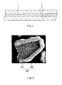
- FIG. 1 is a sectional view illustrating a configuration of an anode for lithium-ion secondary battery according to an embodiment of the invention.
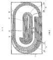
- FIG. 2 is a scanning electron microscope (SEM) photograph illustrating a sectional structure of an anode active material particle.
- FIG. 3 is a HAADF-STEM photograph illustrating an enlarged sectional structure of an anode active material particle (in which a coating section is amorphous).
- FIG. 4 is a HAADF-STEM photograph illustrating an enlarged sectional structure of an anode active material particle (in which a coating section is low-crystalline).
- FIG. 5 is another HAADF-STEM photograph illustrating an enlarged sectional structure of an anode active material particle (in which a coating section is low-crystalline).
- FIG. 6 is a HAADF-STEM photograph illustrating an enlarged sectional structure of an anode active material particle (in which a coating section is amorphous).
- FIG. 7 is a sectional view illustrating a configuration of a prismatic type secondary battery using the anode for lithium-ion secondary battery according to the embodiment of the invention.
- FIG. 8 is a sectional view taken along a line VIII-VIII of the prismatic type secondary battery illustrated in FIG. 7 .
- FIG. 9 is a schematic plan view illustrating configurations of a cathode and the anode illustrated in FIG. 8 .
- FIG. 10 is a sectional view illustrating a configuration of a cylindrical type secondary battery using the anode for lithium-ion secondary battery according to the embodiment of the invention.
- FIG. 11 is an enlarged sectional view illustrating a part of a spirally wound electrode body illustrated in FIG. 10 .
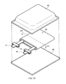
- FIG. 12 is an exploded perspective view illustrating a configuration of a laminate film type secondary battery using the anode for lithium-ion secondary battery according to the embodiment of the invention.
- FIG. 13 is a sectional view taken along a line XIII-XIII of a spirally wound electrode body illustrated in FIG. 12 .
- FIG. 1 illustrates a sectional configuration of an anode for lithium-ion secondary battery (hereinafter simply referred to as "anode") according to an embodiment of the invention.
- FIG. 2 is an SEM photograph illustrating a sectional structure of an anode active material particle
- FIGs. 3 to 6 are HAADF-STEM photographs (hereinafter simply referred to as "TEM photographs") each illustrating an enlarged sectional structure of an anode active material particle.
- the anode includes an anode active material layer 2 on an anode current collector 1.
- the anode active material layer 2 may be arranged on both surfaces or only one surface of the anode current collector 1. However, the anode current collector 1 may be removed.
- the anode current collector 1 is made of, for example, a conductive material with good electrochemical stability, electrical conductivity and mechanical strength.
- the conductive material include copper (Cu), nickel (Ni) and stainless, and in particular, a material which does not form an intermetallic compound with lithium (Li) and is alloyed with the anode active material layer 2 is preferable.
- the anode current collector 1 preferably includes carbon (C) and sulfur (S), because the physical strength of the anode current collector 1 is improved; therefore, even if the anode active material layer 2 swells or shrinks during charge and discharge, the anode current collector 1 is less likely to be deformed.
- Examples of such an anode current collector 1 include metal foil doped with carbon and sulfur.
- the contents of carbon and sulfur are not specifically limited, but both of them are preferably 100 ppm or less, because a higher effect is obtained.
- the anode current collector 1 may be roughened as necessary.
- the anode current collector 1 of which surfaces are not roughened is, for example, rolled metal foil, and the anode current collector 1 of which surfaces are roughened is, for example, metal foil subjected to electrolytic treatment or a sandblast process.
- the electrolytic treatment is a method of forming fine particles on a surface of metal foil or the like in an electrolytic bath by an electrolytic method to form a roughened surface.
- Metal foil formed by the electrolytic treatment is generally called "electrolytic foil (for example, electrolytic copper foil)".
- the surfaces of the anode current collector 1 are preferably roughened, because adhesion of the anode active material layer 2 to the anode current collector 1 is improved by a so-called anchor effect.
- the surface roughness (for example, ten-point average roughness Rz) of the anode current collector 1 is not specifically limited, but the surface roughness of the anode current collector 1 is preferably as large as possible in order to improve the adhesion to the anode active material layer 2 by the anchor effect. However, when the surface roughness is too large, the adhesion to the anode active material layer 2 may decline.
- the anode active material layer 2 includes a particulate anode active material (anode active material particles 200) allowed to insert and extract lithium ions, and if necessary, the anode active material layer 2 may further include any other material such as an anode binder or an anode conductor.
- the anode active material particles 200 each include a core section 201 and a coating section 202 which are allowed to insert and extract lithium ions, and a part or a whole of a surface of the core section 201 is coated with the coating section 202.
- a state where the surface of the core section 201 is coated with the coating section 202 is confirmed by an SEM photograph and a TEM photograph.
- the crystalline states of the core section 201 and the coating section 202 are confirmed by a HAADF-STEM photograph.
- the core section 201 includes one kind or two or more kinds of silicon-based materials (SiO x : 0 ⁇ x ⁇ 0.5, preferably 0 ⁇ x ⁇ 0.45).
- the coating section 202 includes one kind or two or more kinds of silicon-based materials (SiOy: 0.5 ⁇ y ⁇ 1.8).
- x is more preferable, because high energy density is obtained to cause an increase in battery capacity.
- discharge capacity is less likely to decline from an initial stage of charge-discharge cycles.
- "simple substance” means just a general understanding of simple substance (which may include a trace amount of an impurity (elements except for oxygen)), and does not necessarily mean simple substance with a purity of 100%.
- the silicon-based material of the coating section 202 is silicon oxide.
- the core section 201 includes the silicon-based material (SiO x : 0 ⁇ x ⁇ 0.5), because compared to the case where another silicon-based material (SiO x : 0.5 ⁇ x) is included, lithium ions are easily inserted and extracted during charge and discharge. Therefore, a high battery capacity or the like is obtained.
- the coating section 202 includes the silicon-based material (SiOy: 0.5 ⁇ y ⁇ 1.8), because compared to the case where another silicon-based material (SiO y : y ⁇ 0.5) is included, the core section 201 is chemically and physically protected by the coating section 202 while securing insertion and extraction of lithium ions in the core section 201.
- the coating section 202 when the coating section 202 is inserted between the core section 201 and an electrolytic solution, the high-reactive core section 201 is less likely to come into contact with the electrolytic solution; therefore, the decomposition reaction of the electrolytic solution is prevented.
- the coating section 202 is formed of a material including the same base as that of the core section 201 (a material including silicon as a constituent element), the adhesion of the coating section 202 to the core section 201 is improved.
- the silicon-based material (SiO y : 0.5 ⁇ y ⁇ 1.8) of the coating section 202 is more flexible (has a more deformable property) than the silicon-based material (SiO x : 0 ⁇ x ⁇ 0.5) of the core section 201. Therefore, when the core section 201 swells and shrinks during charge and discharge, the coating section 202 swells and shrinks accordingly, thereby maintaining the coating state of the core section 201 with the coating section 202 even after charge and discharge. In other words, even if the core section 201 swells and shrinks, the coating section 202 is resistant to breakage (such as fracture).
- the coating section 202 may be applied to a part or a whole of the surface of the core section 201.
- the coating section 202 may be applied to a plurality of parts of the surface of the core section 201, because as long as the coating section 202 is applied to only a part of the surface of the core section 201, unlike the case where the coating section 202 is not applied at all, an advantage by the protection function of the coating section202 is obtained.
- the anode active material particles 200 may be observed by an SEM or a TEM. Moreover, the anode active material particles 200 may be analyzed by, for example, X-ray photoelectron spectroscopy (XPS) or energy dispersive X-ray spectroscopy (EDX).
- XPS X-ray photoelectron spectroscopy
- EDX energy dispersive X-ray spectroscopy
- the compositions (kinds of silicon-based materials) of the core section 201 and the coating section 202 are allowed to be confirmed.
- the coating section 202 may be dissolved and removed by hydrofluoric acid or the like.
- the quantity of the anode active material particle 200 (the core section 201 coated with the coating section 202) is determined by a combustion method to determine the amounts of silicon and oxygen in the whole anode active material particle 200 by calculation.
- the coating section 202 is removed by washing with hydrofluoric acid, and then the quantity of the core section 201 is determined by the combustion method to determine the amounts of silicon and oxygen in the core section 201 by calculation.
- the amounts of silicon and oxygen in the core section 201 are subtracted from the amounts of silicon and oxygen in the whole anode active material particle 200 to determine the amounts of silicon and oxygen in the coating section 202, respectively.
- the amounts of silicon and oxygen in the core section 201 and the coating section 202 are thereby specified; therefore, the oxidation degrees of the core section 201 and the coating section 202 are allowed to be specified.
- the core sections 201 not coated with the coating section 202 may be used with the core section 201 coated with the coating section 202 to measure the oxidation degrees.
- the coating section 202 is amorphous or low-crystalline, because lithium ions are diffused more easily than the case where the coating section 202 is crystalline (high-crystalline); therefore, even if the surface of the core section 201 is coated with the coating section 202, lithium ions are smoothly inserted and extracted in the core section 201. In other words, even if the core section 201 is coated with the coating section 202, the insertion and extraction of lithium ions are less likely to be inhibited.
- the coating section 202 is preferably amorphous, because the flexibility of coating section 202 is improved; therefore, the coating section 202 easily follows swelling and shrinkage of the core section 201 during charge and discharge. Moreover, as the coating section 202 is resistant to trapping lithium ions, the insertion and extraction of lithium ions in the core section 201 are less likely to be inhibited.
- FIGs. 3 and 6 illustrate the case where the core section 201 is made of high-crystalline silicon (Si) and the coating section 202 is made of amorphous silicon oxide (SiO).
- FIGs. 4 and 5 illustrate the case where the core section 201 is made of high-crystalline silicon and the coating section 202 is made of low-crystalline silicon oxide (SiO).
- low-crystalline means that the silicon-based material of the coating section 202 has both of an amorphous region and a crystalline region, and is different from “amorphous” meaning that the silicon-based material has only an amorphous region.
- the coating section 202 may be observed by a HAADF-STEM or the like.
- the coating section 202 is low-crystalline.
- the crystalline region is observed as a region having a granular contour (a crystal grain).
- a striped pattern crystal lattice fringes
- a difference between "amorphous” and “low-crystalline” is clear from TEM photographs illustrated in FIGs. 3 and 4 .
- the coating section 202 is amorphous, as illustrated in FIG. 3 , only an amorphous region is observed, and a crystalline region (a crystal grain having crystal lattice fringes) is not observed.
- the coating section 202 is low-crystalline, as illustrated in FIG. 4 , a state where crystal grains (parts indicated by arrows) are dotted is observed.
- the crystal grain has crystal lattice fringes with predetermined spacings according to the lattice spacing d of silicon, so the crystal grain is clearly distinguished from the amorphous region around the crystal grain.
- Steps of observing the coating section 202 by the HAADF-STEM are as follows. First, an adhesive is applied to a surface of a grid for TEM made of copper, and then a sample (anode active material particles) is sprinkled on the adhesive. Next, a carbon material (graphite) is deposited on a surface of a powder sample by a vacuum evaporation method. Then, a thin film (Pt/W) is deposited on a surface of the carbon material by a focused ion beam (FIB) method, and then thin film processing is further performed (at an accelerating voltage of 30 kV). Finally, a sectional surface of the anode active material particle is observed by the HAADF-STEM (at an accelerating voltage of 200 kV).
- This observing method is a sensitive technique to the composition of the sample, and in general, an image with bright contrast substantially proportional to the square of an atomic number is obtained.
- the level of low crystallinity of the coating section 202 is not specifically limited, but the average area proportion of crystal grains corresponding to (111) plane and (220) plane of silicon is preferably 35% or less, more preferably 25% or less and more preferably 20% or less, because a higher effect is obtained.
- a crystal grain corresponding to (111) plane is a crystalline region having crystal lattice fringes with a lattice spacing d of 0.31 nm
- a crystal grain corresponding to (220) plane is a crystalline region having crystal lattice fringes with a lattice spacing d of 0.19 nm.
- Steps of determining the average area proportion by calculation are as follows. First, as illustrated in FIG. 5 , a sectional surface of the coating section 202 is observed by a HAADF-STEM to obtain a TEM photograph. In this case, observation is made under an observation magnification of 1.2 ⁇ 10 6 times in an observation area of 65.6 nmx65.7 nm. FIG. 5 is the same TEM photogram as that in FIG. 4 . Next, the presence or absence of crystal lattice fringes, the value of the lattice spacing d and the like are determined to specify a range where crystal grains corresponding to (111) plane and (220) plane of silicon are present, and then the contours of the crystal grains are drawn in the TEM photograph.
- the drawings of these contours and calculation of the area proportion may be carried out artificially, or mechanically by exclusive processing software.
- calculation of the area proportion in 40 areas is carried out, and then the average value (average area proportion) of the determined area proportions on the areas is determined by calculation.
- the coating section 202 is divided into two equal parts in a thickness direction and the area proportions in 20 areas of an inner part and 20 area of an outer part are determined by calculation.
- the average particle diameter of the above-described crystal grains corresponding to (111) plane and (220) plane is not specifically limited, but the average particle diameter is preferably 55 nm or less, and more preferably 50 nm or less, because a higher effect is obtained. Steps of determining the average particle diameter are the same as those in the case where the average area proportion is determined by calculation, except that the average particle diameter per area is determined by calculation, and then the average value (a final average particle diameter) of the average diameters is determined by calculation.
- the contour of the crystal grain is converted into a circle (a circle with an area equal to that of a shape demarcated by the contour of the crystal grain is specified), and then the diameter of the circle is considered as the particle diameter.
- the calculation of the particle diameter may be carried out artificially or mechanically as in the case where the average area proportion is determined.
- the average area proportions of the inner part and the outer part may be the same as or different from each other.
- the average area proportion of crystal grains in the inner part is equal to or larger than that of crystal grains in the outer part (average area proportion in the inner part ⁇ average area proportion in the outer part), because a higher effect is obtained.
- the area proportions and the average particle diameters in 20 areas of the inner part and 20 areas of the outer part are determined by calculation to determine the average area proportions and the average particle diameters in the inner part and the outer part.
- the coating section 202 may be configured of a single layer or a plurality of layers, but as illustrated in FIG. 6 , the coating section 202 is preferably configured of a plurality of layers, because a higher effect is obtained. More specifically, in the case of the coating section 202 configured of a single layer, depending on the thickness of the coating section 202, it is difficult to release the internal stress of the coating section 202; therefore, there is a possibility that when the core section 201 swells and shrinks during charge and discharge, the coating section 202 is broken (cracked, peeled or the like). However, in the case of the coating section 202 configured of a plurality of layers, the internal stress is easily released; therefore, the coating section 202 is resistant to breakage. A broken line illustrated in FIG. 6 indicates an index of a boundary between layers. Note that a whole or a part of the coating section 202 may be configured of a plurality of layers.
- the coating section 202 has a fibrous shape (a fluffy shape) around a surface thereof, but the shape of the coating section 202 is not limited thereto, because whether the coating section 202 has the fibrous shape does not have a large influence on the protection function of the coating section 202.
- the core section 201 may be crystalline (high-crystalline), low-crystalline or amorphous, and in particular, the core section 201 is preferably high-crystalline or low-crystalline, and more preferably high-crystalline, because lithium ions are inserted and extracted easily during charge and discharge; therefore, a high battery capacity or the like is obtained. Moreover, it is because the core section 201 is resistant to swelling and shrinkage during charge and discharge.
- the half-width (2 ⁇ ) of a diffraction peak corresponding to (111) crystal plane of silicon obtained by X-ray diffraction is preferably 20° or less, and the crystallite size corresponding to the (111) crystal plane is preferably 10 nm or over, because a higher effect is obtained.
- the median diameter of the core section 201 is not specifically limited, but the median diameter of the core section 201 is preferably within a range of 0.5 ⁇ m to 20 ⁇ m both inclusive, because lithium ions are easily inserted and extracted in the core section 201 during charge and discharge, and the core section 201 is resistant to cracking. More specifically, when the median diameter is smaller than 0.5 ⁇ m, the total surface area of the core section 201 is too large, and there is a possibility that the core section 201 easily swells and shrinks during charge and discharge. On the other hand, when the median diameter is larger than 20 ⁇ m, there is a possibility that the core section 201 is susceptible to cracking during charge and discharge.
- the average thickness of the coating section 202 is not specifically limited, but the average thickness is as small as possible, and is preferably within a range of 1 nm to 5000 nm both inclusive, more preferably within a range of 100 nm to 5000 nm both inclusive, because lithium ions are easily inserted and extracted in the core section 201, and the protection function of the coating section 202 is effectively fulfilled. More specifically, when the average thickness is smaller than 1 nm, there is a possibility that it is difficult for the coating section 202 to protect the core section 201.
- the silicon-based material (SiO y : 0.5 ⁇ y ⁇ 1.8) of the coating section 202 has properties of easily inserting lithium ions and being resistant to extracting the lithium ions once inserted thereinto.
- the average thickness of the coating section 202 is determined by the following steps. First, as illustrated in FIG. 2 , one anode active material particle 200 is observed by an SEM. The observation magnification is preferably a magnification allowed to visually confirm (determine) a boundary between the core section 201 and the coating section 202 in order to measure a thickness T of the coating section 202. Next, the thicknesses T of the coating section 202 at arbitrary 10 points are measured, and then the average value (the average thickness T per anode active material particle) of the thicknesses T at 10 points is determined by calculation. In this case, it is preferable to set measurement points so that the measurement points are not focused on a specific area and are spread as widely as possible.
- the above-described steps of determining the average value by calculation are repeated until the total number of anode active material particles observed by the SEM reaches 100.
- the average value (the average value of the average thicknesses T) of the average values (the average thicknesses T on a per-particle basis) of the 100 anode active material particles 200 is determined as the average thickness of the coating section 202.
- the average coverage of the coating section 202 is not specifically limited, but the average coverage is preferably as large as possible, and in particular, the average coverage is preferably 10% or over, and more preferably 30% or over, because the protection function of the coating section202 is further improved.
- the average coverage of the coating section 202 is determined by the following steps. First, as in the case where the average thickness is determined, one anode active material particle 200 is observed by the SEM.
- the observation magnification is preferably a magnification allowed to visually distinguish a part coated with the coating section 202 of the core section 201 from a part not coated with the coating section 202 of the core section 201.
- the above-described steps of determining the coverage are repeated until the total number of the anode active material particles observed by the SEM reaches 100. Finally, the average value of the coverages (coverages on a per-particle basis) of 100 anode active material particles 200 is determined as the average coverage of the coating section 202.
- the core section 201 preferably includes iron (Fe), and the iron content is preferably 0.01 wt% or over, because the electrical resistance of the core section 201 is reduced.
- a part or a whole of iron included in the core section 201 may be alloyed with a silicon-based material.
- the composition of the core section 201 including iron is allowed to be confirmed by, for example, EDX.
- the core section 201 may include one kind or two or more kinds of other metal materials with iron, because the electrical resistance of the core section 201 is further reduced.
- other metal materials include aluminum (Al), calcium (Ca), manganese (Mn), chromium (Cr), magnesium (Mg) and nickel (Ni). The contents of the other metal materials are arbitrarily set.
- the core section 201 preferably includes aluminum instead of iron, and the aluminum content (in atomic ratio excluding oxygen) is preferably within a range of 0.1 at% to 50 at% both inclusive, because the core section 201 becomes low-crystalline; therefore, the core section 201 is resistant to swelling and shrinkage during charge and discharge, and diffusibility of lithium ions is improved. Moreover, it is because the electrical resistance of the core section 201 is reduced.
- a part or a whole of aluminum included in the core section 201 may be alloyed with a silicon-based material. The same applies to a metal material such as chromium which will be described later.
- the core section 201 may include one kind or two or more kinds of other metal materials with aluminum, because the electrical resistance of the core section 201 is further reduced.
- other metal material include one or more kinds selected from chromium, iron and nickel.
- the content (the atomic ratio excluding oxygen) of the metal material is preferably within a range of 1 at% to 50 at% both inclusive, because a higher effect is obtained.
- the core section 201 may further include, in addition to aluminum and the other metal material which are described above, any other metal material or the like except for them, because the core section 201 is more resistant to swelling and shrinkage during charge and discharge.
- the metal material or the like one or more kinds selected from boron (B), magnesium, calcium, titanium (Ti), vanadium (V), manganese, cobalt (Co), copper, germanium (Ge), yttrium (Y), zirconium (Zr), molybdenum (Mo), silver (Ag), indium (In), tin (Sn), antimony (Sb), tantalum (Ta), tungsten (W), lead (Pb), lanthanum (La), cerium (Ce), praseodymium (Pr) and neodymium (Nd) are used.
- the content (the atomic ratio excluding oxygen) of the metal material or the like is preferably within a range of 0.01 at% to 30 at% both inclusive, because a higher
- composition of the above-described core section 201 including aluminum or the like is confirmed by, for example, EDX.
- atomic ratio excluding oxygen means a ratio (atomic ratio) of a specific element in all elements configuring the core section 201 except for oxygen.
- the aluminum content means the ratio (at%) of aluminum in silicon and aluminum.
- the core section 201 further includes, in addition to aluminum and the other metal material (such as chromium), the other metal material or the like (such as boron), the silicon content (the atomic ratio excluding oxygen) in the core section 201 is not specifically limited, but the silicon content is preferably within a range of 20 at% to 80 at% both inclusive, because while securing the capacity of an anode, the core section 201 is resistant to swelling and shrinkage during charge and discharge.
- the other metal material such as chromium
- the other metal material or the like such as boron
- the silicon content (the atomic ratio excluding oxygen) in the core section 201 is not specifically limited, but the silicon content is preferably within a range of 20 at% to 80 at% both inclusive, because while securing the capacity of an anode, the core section 201 is resistant to swelling and shrinkage during charge and discharge.
- the half-width (2 ⁇ ) of a diffraction peak corresponding to (111) crystal plane of silicon obtained by X-ray diffraction is preferably 0.6° or over, and the crystallite size corresponding to the (111) crystal plane is preferably 90 nm or less.
- the coating section 202 is dissolved with hydrofluoric acid or the like and removed, and then the core section 201 is analyzed.
- the core section 201 does not include aluminum and is high-crystalline, as described above, the core section 201 is resistant to swelling and shrinkage during charge and discharge.
- the core section 201 includes a predetermined amount of aluminum, irrespective of whether the core section 201 is high-crystalline or low-crystalline, the core section 201 is resistant to swelling and shrinkage during charge and discharge.
- the diffusibility of lithium ions is improved.
- the coating section 202 is preferably placed adjacent to the core section 201, but an intermediate film including a natural oxide film (silicon dioxide: SiO 2 ) may be arranged between the core section 201 and the coating section 202.
- the intermediate film is formed, for example, by oxidizing a part in proximity to a surface of the core section 201.
- the amorphous silicon-based material (SiOy) included in the coating section 202 has 5 kinds of bonding states (valence numbers) of silicon atoms to oxygen atoms including zero-valence (Si 0+ ), monovalence (Si 1+ ), divalence (Si 2+ ), trivalence (Si 3+ ) and tetravalence (Si 4+ ).
- the presence or absence of a silicon atom in each bonding state and the abundance ratio of the bonding states are allowed to confirmed, for example, by analyzing the silicon-based material by XPS.
- silicon dioxide is dissolved with hydrofluoric acid or the like and removed, and then analyzed.
- the amorphous silicon-based material (SiOy: 0.5 ⁇ y ⁇ 1.8) has all of the above-described bonding states of silicon atoms to oxygen atoms (5 kinds including zero-valence to tetravalence) and these bonding state are mixed, because compared to the case where the amorphous silicon-based material has some of the bonding states, the electrical resistance of the coating section 202 is reduced, and the protection function of the coating section 202 for the core section 201 is secured. More specifically, a zero-valent bonding state in which the valence number is the smallest tends to swell and shrink the core section 201 during charge and discharge to cause degradation in a chemical and physical protection function of the coating section 202 for the core section 201.
- the amorphous silicon-based material has monovalent to trivalent bonding states in addition to the zero-valent and tetravalent bonding states and the valent numbers (bonding states) are spread so as not to make the abundance ratios of the zero-valent and tetravalent bonding states too large.
- the abundance ratio (atomic ratio) of the bonding states of silicon atoms is not specifically limited, because as long as the amorphous silicon-based material has 5 kinds of bonding states, the above-described advantages are obtained independent of the abundance ratio.
- the abundance ratio preferably satisfies a relationship of Si 0+ ⁇ Si 1+ +Si 2+ +Si 3+ +Si 4+ , because the smaller the ratio of the zero-valent bonding state is, the more easily the protection function of the coating section 202 is fulfilled.
- the abundance ratio preferably satisfies relationships of Si 1+ ⁇ Si 3+ , Si 2+ ⁇ S. 3+ Si 1+ ⁇ Si 4+ and Si 2+ ⁇ Si 4+ , because the larger the ratio of silicon atoms with a large valence number is, the more easily the protection function of the coating section 202 is fulfilled.
- the ratio of silicon atoms with a large valence number is preferably large. Therefore, the abundance ratio of the tetravalent bonding state in which the valence number is the largest is preferably 20 at% or over, and more preferably 30 at% or over.
- the anode active material particles 200 each may further include an additional coating film which is applied to a part or a whole of a surface of the coating section 202, because the core section 201 is less likely to come into contact with an electrolytic solution.
- the additional coating film includes, for example, one kind or two or more kinds selected from carbon materials, metal materials and inorganic compounds. Examples of the carbon materials include graphite. Examples of the metal materials include iron, copper and aluminum. Examples of the inorganic compounds include silicon dioxide (SiO 2 ).
- a carbon material or a metal material with lower electrical resistance than the core section 201 and the coating section 202 is preferable, because the electrical resistance of the whole anode active material particles 200 is reduced.
- anode binder for example, one kind or two or more kinds of synthetic rubber or polymeric materials are used.
- synthetic rubber include styrene butadiene-based rubber, fluorine-based rubber and ethylene propylene diene.
- polymeric materials include polyvinylidene fluoride, polyimide, polyamideimide, polyacrylic acid and lithium polyacrylate.
- anode conductor for example, one kind or two or more kinds of carbon materials such as graphite, carbon black, acetylene black and ketjen black are used.
- the anode conductor may be a metal, a conductive polymer or the like, as long as the metal, the conductive polymer or the like is a material having electrical conductivity.
- the anode active material layer 2 may include a carbon material as an additional anode active material, because the electrical resistance of the anode active material layer 2 is reduced, and the anode active material layer 2 is resistant to swelling and shrinkage during charge and discharge.
- the carbon material include graphitizable carbon, non-graphitizable carbon having the (002) plane with a surface separation of 0.37 nm or over, and graphite having the (002) plane with a surface separation of 0.34 nm or over. More specific examples include pyrolytic carbons, cokes, glass-like carbon fibers, an organic polymer compound fired body, activated carbon and carbon blacks. Cokes include pitch coke, needle coke, and petroleum coke.
- the organic polymer compound fired body is a material carbonized by firing a phenolic resin, a furan resin or the like at an appropriate temperature.
- the carbon material may have any of a fibrous shape, a spherical shape, a granular shape, and a scale-like shape.
- the content of the carbon material in the anode active material layer 2 is not specifically limited, but the content is preferably 60 wt% or less and more preferably within a range of 10 wt% to 60 wt% both inclusive.
- the anode active material layer 2 may include, in addition to the above-described anode active material particles 200 including the core sections 201 and the coating sections 202, any other kind of anode active material particles.
- the other kind of anode active material particles include a material including one or both of silicon and tin as constituent elements (except for the above-described silicon-based materials), metal oxides and polymers.
- the material including one or both of silicon and tin as constituent elements include silicon compounds, silicon alloys, a simple substance of tin, tin compounds and tin alloys.
- the metal oxides include iron oxide, ruthenium oxide and molybdenum oxide.
- the polymers include polyacetylene, polyaniline and polypyrrole.
- the anode active material layer 2 is formed by, for example, a coating method, a firing method (a sintering method) or a combination of two or more kinds of the methods.
- a coating method for example, anode active material particles are mixed with the anode binder or the like to form a mixture, and the mixture is dispersed in an organic solvent, and then coating with the mixture is performed.
- the firing method after coating is performed by the same steps as those in the coating method, the mixture is heated at a higher temperature than the melting point of the anode binder or the like.
- the firing method a known technique may be used. Examples of the firing method include an atmosphere firing method, a reaction firing method, a hot press firing method and the like.
- the anode is manufactured by, for example, the following steps.
- the parcitule (powdery) core section 201 including the silicon-based material (SiO x : 0 ⁇ x ⁇ 0.5) is obtained by, for example, a gas atomization method, a water atomization method or a melt-pulverization method.
- the core section 201 includes a metal material such as iron or aluminum, or the like, the metal material or the like is melted with row materials.
- the coating section 202 including the silicon-based material (SiO y : 0.5 ⁇ y ⁇ 1.8) is formed on a surface of the core section 201 by, for example, a vapor-phase growth method such as an evaporation method or a sputtering method.
- a vapor-phase growth method such as an evaporation method or a sputtering method.
- the silicon-based material tends to become amorphous.
- the coating section 202 may be formed by depositing the silicon-based material on heating, or the coating section 202 may be formed and then heated to make the silicon-based material low-crystalline.
- the level of low crystallinity is controlled depending on conditions such as a temperature and duration on heating.
- the coating section 202 By this heating process, moisture in the coating section 202 is removed, and adhesion of the coating section 202 to the core section 201 is improved.
- the coating section 202 is formed, the abundance ratio of the bonding states of the silicon atoms are controllable by adjusting the introduction amounts of oxygen (O 2 ), hydrogen (H 2 ) and the like into a chamber or adjusting the temperature of the core section 201. Therefore, the core section 201 is coated with the coating section 202 so as to obtain the anode active material particles 200.
- the additional coating film may be formed on the surface of the coating section 202 by a vapor-phase growth method such as an evaporation method, a sputtering method or a chemical vapor deposition (CVD) method, a wet coating method, or the like.
- a vapor-phase growth method such as an evaporation method, a sputtering method or a chemical vapor deposition (CVD) method, a wet coating method, or the like.
- the additional coating film is deposited by directly spraying steam to the surfaces of the anode active material particles 200.
- the additional coating film is deposited by a powder sputtering method while introducing an argon gas (Ar).
- Ar argon gas
- the CVD method for example, a gas formed by subliming a metal chloride and a mixed gas including hydrogen, nitrogen and the like are mixed so that the molar ratio of the metal chloride is 0.03 to 0.3, and then the gas is heated at 1000°C or over to deposit the additional coating film on the surface of the coating section 202.
- an alkali solution is added to slurry including the anode active material particles 200 while adding a metal-containing solution to the slurry to form a metal hydroxide, and then reduction treatment by hydrogen is performed at 450°C to deposit the additional coating film on the surface of the coating section 202.
- the carbon material is used as a material for forming the additional coating film
- the anode active material particles 200 are charged into a chamber, and an organic gas is introduced into the chamber, and then heating treatment is performed under 10000 Pa and 1000°C or over for 5 hours to deposit the additional coating film on the surface of the coating section 202.
- the kind of the organic gas is not specifically limited as long as the organic gas forms carbon by thermal decomposition, and examples of the organic gas include methane, ethane, ethylene, acetylene and propane.
- anode active material particles 200 and other materials such as the anode binder are mixed to form an anode mixture, and then the anode mixture is dissolved in a solvent such as an organic solvent to form anode mixture slurry. Finally, the anode mixture slurry is applied to the surface of the anode current collector 1, and is dried to form the anode active material layer 2. After that, if necessary, anode active material layer 2 may be compression molded and heated (fired).
- the anode active material particles 200 each include the core section 201 and the coating section 202.
- the core section 201 includes the silicon-based material (SiO x : 0 ⁇ x ⁇ 0.5)
- the coating section 202 includes the amorphous or low-crystalline silicon-based material (SiO y : 0.5 ⁇ y ⁇ 1.8). Therefore, lithium ions are smoothly inserted and extracted in the core section 201, and the core section 201 is protected by the coating section 202 so as not to expose a newly-formed surface during charge and discharge while maintaining smooth insertion and extraction. Accordingly, the anode is allowed to contribute to an improvement in performance of a lithium-ion secondary battery using the anode, more specifically improvements in cycle characteristics, initial charge-discharge characteristics and the like of the lithium-ion secondary battery.
- the coating section 202 when the average area proportion of crystal grains corresponding to (111) plane and (220) plane of silicon is 35% or less, or when the average particle diameter of the crystal grains is 55 nm or less, a higher effect is obtainable. Moreover, when, in the case where the coating section 202 is divided into two equal parts in a thickness direction, the above-described average area proportions and the above-described average particle diameters of crystal grains in an inner part is equal to or larger than those of crystal grains in an outer part, or when the coating section 202 is configured of a plurality of layers, a higher effect is obtained.
- the median diameter of the core section 201 is within a range of 0.5 ⁇ m to 20 ⁇ m both inclusive, or when the core section 201 includes 0.01 wt% or over of iron, a higher effect is obtainable. Even in the case where the average thickness of the coating section 202 is within a range of 1 nm to 5000 nm both inclusive, or the average coverage of the coating section 202 is 30% or over, a higher effect is obtainable.
- the anode current collector 1 includes 100 ppm or less of carbon and sulfur, a higher effect is obtainable.
- the core section 201 includes a predetermined amount of a metal material such as aluminum, or the like, a higher effect is obtainable.
- the anode is allowed to contribute to improvements in not only the cycle characteristics and the initial charge-discharge characteristics but also load characteristics.
- the silicon content in the core section 201 is within a range of 20 at% to 80 at% both inclusive, or when the half-width (2 ⁇ ) of a diffraction peak corresponding to (111) crystal plane of silicon obtained by X-ray diffraction in the core section 201 is 20° or less and the crystallite size is 10 nm or over, a higher effect is obtainable.
- the bonding state of silicon atoms to oxygen atoms in the amorphous silicon-based material in the coating section 202 is a mixed state of zero-valence to tetravalence
- the protection function of the coating section 202 for the core section 201 is allowed to be secured while reducing the electrical resistance of the coating section 202.
- the abundance ratio (atomic ratio) of the bonding states satisfies a relationship of Si 0+ ⁇ Si 1+ +Si 2+ +Si 3+ +Si 4+ or relationships of Si 1+ ⁇ Si 3+ , Si 2+ ⁇ Si 3+ , Si 1+ ⁇ Si 4+ and Si 2+ ⁇ Si 4+ , a higher effect is obtainable.
- the abundance ratio of the tetravalent bonding state is 20 at% or over, preferably 30 at% or over.
- anode active material particles 200 each include the additional coating film with lower electrical resistance than the electrical resistance of the core section 201 and the coating section 202, a higher effect is obtainable.
- Lithium-ion secondary battery Next, lithium-ion secondary batteries using the above-described anode for lithium-ion secondary battery will be described below.
- FIGs. 7 and 8 illustrate sectional configurations of a prismatic type secondary battery
- FIG. 8 illustrates a sectional view taken along a line VIII-VIII of FIG. 7
- FIG. 9 illustrates planar configurations of a cathode 21 and an anode 22 illustrated in FIG. 8 .
- the prismatic type secondary battery is formed mainly by containing a battery element 20 in a battery can 11.
- the battery element 20 is a spirally wound laminate formed by laminating the cathode 21 and the anode 22 with a separator 23 in between and spirally winding them, and has a flat shape according to the shape of the battery can 11.
- the battery can 11 is, for example, a prismatic package member.
- a sectional surface in a longitudinal direction has a rectangular shape or a substantially rectangular shape (including a curve in part), and the prismatic package member is applicable to not only a prismatic battery with a rectangular shape but also a prismatic battery with an oval shape.
- the prismatic package member is a vessel-shaped member having a rectangular closed end or an oval closed end and an opening with a rectangular shape or a substantially rectangular (oval) shape formed by connecting arcs with straight lines.
- FIG. 8 illustrates the battery can 11 having a rectangular sectional surface.
- the battery can 11 is made of, for example, a conductive material such as iron or aluminum or an alloy thereof, and may have a function as an electrode terminal.
- a conductive material such as iron or aluminum or an alloy thereof
- iron which is harder than aluminum is preferable.
- iron may be plated with nickel or the like.
- the battery can 11 has a hollow configuration having an open end and a closed end, and the battery can 11 is sealed by an insulating plate 12 and a battery cover 13 attached to the open end.
- the insulating plate 12 is arranged between the battery element 20 and the battery cover 13, and the insulating plate 12 is made of an insulating material such as polypropylene.
- the battery cover 13 is made of, for example, the same material as that of the battery can 11, and may have a function as an electrode terminal as in the case of the battery can 11.
- a terminal plate 14 which is a cathode terminal is arranged outside the battery cover 13, and the terminal plate 14 is electrically insulated from the battery cover 13 by an insulating case 16.
- the insulating case 16 is made of an insulating material such as polybutylene terephthalate.
- a through hole is provided around the center of the battery cover 13, and a cathode pin 15 is inserted into the through hole so as to be electrically connected to the terminal plate 14 and to be electrically insulated from the battery cover 13 by a gasket 17.
- the gasket 17 is made of, for example, an insulating material, and its surface is coated with asphalt.
- a cleavage valve 18 and an injection hole 19 are arranged around an edge of the battery cover 13.
- the cleavage valve 18 is electrically connected to the battery cover 13, and when an internal pressure in the secondary battery increases to a certain extent or higher due to an internal short circuit or external application of heat, the cleavage valve 18 is separated from the battery cover 13 to release the internal pressure.
- the injection hole 19 is filled with a sealing member 19A made of, for example, a stainless steel ball.
- a cathode lead 24 made of a conductive material such as aluminum is attached to an end (for example, an inside end) of the cathode 21, and an anode lead 25 made of a conductive material such as nickel is attached to an end (for example, an outside end) of the anode 22.
- the cathode lead 24 is welded to an end of the cathode pin 15 and is electrically connected to the terminal plate 14.
- the anode lead 25 is welded and electrically connected to the battery can 11.
- the cathode 21 includes a cathode active material layer 21B on both surfaces of a cathode current collector 21A.
- the cathode active material layer 21B may be arranged on only one surface of the cathode current collector 21 A.
- the cathode current collector 21A is made of a conductive material such as aluminum, nickel or stainless.
- the cathode active material layer 21B includes one kind or two or more kinds of cathode materials allowed to insert and extract lithium ions as cathode active materials, and may include any other material such as a cathode binder or a cathode conductor, if necessary. Details of the cathode binder and the cathode conductor are the same as the above-described details of the anode binder and the anode conductor.
- a lithium-containing compound is preferable, because a high energy density is obtained.
- the lithium-containing compound include a complex oxide including lithium and a transition metal element as constituent elements and a phosphate compound including lithium and a transition metal element as constituent elements.
- a compound including one or two or more kinds selected from the group consisting of cobalt, nickel, manganese and iron as transition metal elements is preferable, because a higher voltage is obtained.
- the complex oxide and the phosphate compound are represented by, for example, Li x M1O 2 and Li y M2PO 4 , respectively.
- M1 and M2 represent one or more kinds of transition metal elements.
- the values of x and y depend on a charge-discharge state of the battery, and are generally within a range of 0.05 ⁇ x ⁇ 1.10 and 0.05 ⁇ y ⁇ 1.10, respectively.
- Examples of the complex oxide including lithium and a transition metal element include lithium-cobalt complex oxide (Li x CoO 2 ), lithium-nickel complex oxide (Li x NiO 2 ), and lithium-nickel-based complex oxide represented by a formula (1).
- Examples of the phosphate compound including lithium and a transition metal element include a lithium-iron phosphate compound (LiFePO 4 ), and a lithium-iron-manganese phosphate compound (LiFe 1-u Mn u PO 4 (u ⁇ 1)), because high battery capacity and good cycle characteristics are obtained.
- the cathode material may be any material other than the above-described materials.
- Examples of the material includes a material represented by Li x Ml y O 2 (where M1 is one or more kinds selected from the group consisting of nickel and M represented by the formula (1) (such as cobalt) (29 kinds of metal elements including nickel, cobalt and the like), x is x> 1 and y is arbitrarily selected).
- M is one or more kinds selected from the group consisting of cobalt, manganese, iron, aluminum, vanadium, tin, magnesium, titanium, strontium, calcium, zirconium, molybdenum, technetium, ruthenium, tantalum, tungsten, rhenium, ytterbium, copper, zinc, barium, boron, chromium, silicon, gallium, phosphorus, antimony and niobium, and x is within a range of 0.005 ⁇ x ⁇ 0.5.
- examples of the cathode material include an oxide, a bisulfide, a chalcogenide, and a conductive polymer.
- examples of the oxide include titanium oxide, vanadium oxide and manganese dioxide.
- examples of the bisulfide include titanium bisulfide and molybdenum sulfide.
- examples of the chalcogenide include niobium selenide.
- examples of the conductive polymer include sulfur, polyaniline and polythiophene.
- the anode 22 has the same configuration as that of the above-described anode for lithium-ion secondary battery, and includes an anode active material layer 22B on both surfaces of an anode current collector 22A.
- the configurations of the anode current collector 22A and the anode active material layer 22B are the same as those of the anode current collector 1 and the anode active material layer 2, respectively.
- the chargeable capacity of the anode material allowed to insert and extract lithium ions is preferably larger than the discharge capacity of the cathode 21, because lithium metal is prevented from being deposited without intention during charge and discharge.
- the cathode active material layer 21B is arranged on a part (for example, a central region in a longitudinal direction) of a surface of the cathode current collector 21 A.
- the anode active material layer 22B is arranged on a whole surface of the anode current collector 22A. Therefore, the anode active material layer 22B is arranged in a region (an opposed region R1) opposed to the cathode active material layer 21B and a region (a non-opposed region R2) not opposed to the cathode active material layer 21B in the anode current collector 22A.
- the anode active material particles included in the anode active material layer 22B each include a core section (SiO x : 0 ⁇ x ⁇ 0.5) and a low-crystalline coating section (SiO y : 0.5 ⁇ y ⁇ 1.8).
- a core section SiO x : 0 ⁇ x ⁇ 0.5
- a low-crystalline coating section SiO y : 0.5 ⁇ y ⁇ 1.8.
- the formation states of the core section and the coating section may be changed from states at the time of formation of the anode active material layer 22B.
- the formation state of the anode active material layer 22B is hardly affected by charge and discharge and is maintained; therefore, the presence or absence of the core section and the coating section, compositions of the core section and the coating section, and the like are preferably examined in the anode active material layer 22B in the non-opposed region R2, because the presence or absence of the core section and the coating section, compositions of the core section and the coating section, and the like are allowed to be reproducibly and accurately examined independent of charge-discharge history (such as the presence or absence of charge and discharge and the number of times of charge and discharge). The same applies to the case where the abundance ratio of the bonding states of silicon atoms is examined.
- anode utilization ratio The maximum utilization ratio in a fully-charged state of the anode 22 (hereinafter simply referred to as "anode utilization ratio”) is not specifically limited, and is allowed to be arbitrarily set according to the ratio of the capacity of the cathode 21 and the capacity of the anode 22.
- the insertion amount X is allowed to be determined by the following steps. First, the secondary battery is charged to a fully-charged state, and then the secondary battery is disassembled, and a part (a test anode) opposed to the cathode 21 is cut from the anode 22. Next, an evaluation battery including metal lithium as an opposite electrode is assembled with use of the test anode. Finally, the evaluation battery is discharged to measure the discharge capacity at the time of initial discharge, and then the discharge capacity is divided by the area of the test anode to determine the insertion amount X.
- discharge means that a current flows in a direction where lithium ions are extracted from the test anode, and, for example, the battery is discharged at a constant current and a current density of 0.1 mA/ cm 2 until the battery voltage reaches 1.5 V.
- the insertion amount Y is determined, for example, by charging the above-described discharged evaluation battery at a constant current and a constant voltage until the battery voltage reaches 0 V and measuring the charge capacity, and then dividing the charge capacity by the area of the test anode.
- charge means that a current flows in a direction where lithium ions are inserted into the test anode, and, for example, the battery is charged at a current density of 0.1 mA/cm 2 and a constant battery voltage of 0 V until the current density reaches 0.02 mA/ cm 2 .
- the anode utilization ratio is preferably within a range of 35% to 80% both inclusive, because good cycle characteristics, initial charge-discharge characteristics and load characteristics are obtained.
- the separator 23 isolates between the cathode 21 and the anode 22 so that lithium ions pass therethrough while preventing a short circuit of a current due to contact between the cathode 21 and the anode 22.
- the separator 23 is configured of, for example, a porous film of a synthetic resin or ceramic, and may be configured of a laminate film formed by laminating two or more kinds of porous films.
- the synthetic resin include polytetrafluoroethylene, polypropylene and polyethylene.
- Electrolytic solution The separator 23 is impregnated with an electrolytic solution which is a liquid electrolyte.
- the electrolytic solution is formed by dissolving an electrolyte salt in a solvent, and may include any other material such as an additive, if necessary.
- the solvent includes, for example, one kind or two or more kinds of nonaqueous solvents such as organic solvents.
- nonaqueous solvent include ethylene carbonate, propylene carbonate, butylene carbonate, dimethyl carbonate, diethyl carbonate, ethyl methyl carbonate, methyl propyl carbonate, ⁇ -butyrolactone, ⁇ -valerolactone, 1,2-dimethoxyethane, tetrahydrofuran, 2-methyltetrahydrofuran, tetrahydropyran, 1,3-dioxolane, 4-methyl-1,3-dioxolane, 1,3-dioxane, 1,4-dioxane, methyl acetate, ethyl acetate, methyl propionate, ethyl propionate, methyl butyrate, methyl isobutyrate, methyl trimethylacetate, ethyl trimethylacetate, acetonitrile, glutaronitrile
- one or more kinds selected from the group consisting of ethylene carbonate, propylene carbonate, dimethyl carbonate, diethyl carbonate and ethyl methyl carbonate are preferable, because superior characteristics are obtained.
- a mixture of a high-viscosity (high dielectric constant) solvent (for example, specific inductive ⁇ 30) such as ethylene carbonate or propylene carbonate and a low-viscosity solvent (for example, viscosity ⁇ 1 mPa ⁇ s) such as dimethyl carbonate, ethyl methyl carbonate or diethyl carbonate is more preferable, because the dissociation property of the electrolyte salt and ion mobility are improved.
- the nonaqueous solvent preferably includes one or both of a halogenated chain carbonate and a halogenated cyclic carbonate, because a stable coating film is formed on a surface of the anode 22 during charge and discharge; therefore, the decomposition reaction of the electrolytic solution is prevented.
- the halogenated chain carbonate is a chain carbonate including a halogen as a constituent element (in which one or more hydrogen atoms are substituted with a halogen atom).
- the halogenated cyclic carbonate is a cyclic carbonate including a halogen as a constituent element (in which one or more hydrogen atoms are substituted with a halogen atom).
- halogen is not specifically limited, but fluorine, chlorine or bromine is preferable, and fluorine is more preferable, because a higher effect than that of other halogens is obtained.
- the number of halogen atoms is more preferably 2 than 1, and may be 3 or over, because a capability of forming a protective film is improved, and a firmer and stabler coating film is formed, so the decomposition reaction of the electrolytic solution is further prevented.
- halogenated chain carbonate examples include fluoromethyl methyl carbonate, bis(fluoromethyl) carbonate and difluoromethyl methyl carbonate.
- halogenated cyclic carbonate examples include 4-fluoro-1,3-dioxolane-2-one and 4,5-difluoro-1,3-dioxolane-2-one.
- a geometric isomer is included in the halogenated cyclic carbonate.
- the contents of the halogenated chain carbonate and the halogenated cyclic carbonate in the nonaqueous solvent is, for example, within a range of 0.01 wt% to 50 wt% both inclusive.
- the nonaqueous solvent preferably includes an unsaturated carbon bond cyclic carbonate, because a stable coating film is formed on a surface of the anode 22 during charge and discharge; therefore, the decomposition reaction of the electrolytic solution is prevented.
- the unsaturated carbon bond cyclic carbonate is a cyclic carbonate having an unsaturated carbon bond (in which an unsaturated carbon bond is introduced into a part).
- Examples of the unsaturated carbon bond cyclic carbonate include vinylene carbonate and vinyl ethylene carbonate.
- the content of the unsaturated carbon bond cyclic carbonate in the nonaqueous solvent is, for example, within a range of 0.01 wt% to 10 wt% both inclusive.
- the nonaqueous solvent preferably includes a sultone (a cyclic sulfonate), because chemical stability of the electrolytic solution is improved.
- a sultone a cyclic sulfonate
- examples of the sultone include propane sultone and propene sultone.
- the content of the sultone in the nonaqueous solvent is, for example, within a range of 0.5 wt% to 5 wt% both inclusive.
- the nonaqueous solvent preferably includes an acid anhydride, because chemical stability of the electrolytic solution is improved.
- the acid anhydride include a carboxylic anhydride, a disulfonic anhydride and an anhydride of a carboxylic acid and a sulfonic acid.
- the carboxylic anhydride include succinic anhydride, glutaric anhydride and maleic anhydride.
- the disulfonic anhydride include ethanedisulfonic anhydride and propanedisulfonic anhydride.
- anhydride of a carboxylic acid and a sulfonic acid examples include sulfobenzoic anhydride, sulfopropionic anhydride and sulfobutyric anhydride.
- the content of the acid anhydride in the nonaqueous solvent is, for example, within a range of 0.5 wt% to 5 wt% both inclusive.
- the electrolyte salt includes, for example, one kind or two or more kinds selected from light metal salts such as lithium salt.
- the lithium salt include lithium hexafluorophosphate (LiPF 6 ), lithium tetrafluoroborate (LiBF 4 ), lithium perchlorate (LiClO 4 ), lithium hexafluoroarsenate (LiAsF 6 ), lithium tetraphenyl borate (LiB(C 6 H 5 ) 4 ), lithium methanesulfonate (LiCH 3 SO 3 ), trifluoromethane sulfonic lithium (LiCF 3 SO 3 ), lithium tetrachloroaluminate (LiAlCl 4 ), lithium silicate hexafluoride (Li 2 SiF 6 ), lihtium chloride (LiCl) and lithium bromide (LiBr), because good battery capacity, cyclic characteristics, storage characteristics and the like are obtained.
- lithium hexafluorophosphate lithium tetrafluoroborate, lithium perchlorate and lithium hexafluoroarsenate are preferable. More specifically, lithium hexafluorophosphate and lithium tetrafluoroborate are preferable, and lithium hexafluorophosphate is more preferable, because internal resistance is reduced to thereby obtain superior characteristics.
- the content of the electrolyte salt is preferably within a range of 0.3 mol/kg to 3.0 mol/kg both inclusive relative to the solvent, because high ionic conductivity is obtained.
- prismatic type secondary battery When the prismatic secondary battery is charged, for example, lithium ions extracted from the cathode 21 are inserted into the anode 22 through the electrolytic solution. On the other hand, when the prismatic type secondary battery is discharged, for example, lithium ions extracted from the anode 22 are inserted into the cathode 21 through the electrolytic solution.
- the secondary battery is manufactured by, for example, the following steps.
- the cathode 21 is formed.
- the cathode active material and, if necessary, the cathode binder, the cathode conductor and the like are mixed to form a cathode mixture, and then the cathode mixture is dispersed in an organic solvent or the like to form paste-form cathode mixture slurry.
- the cathode mixture slurry is applied to the cathode current collector 21 A by a coating apparatus such as a doctor blade or a bar coater, and the cathode mixture slurry is dried to form the cathode active material layer 21B.
- the cathode active material layer 21B is compression molded by a roller press or the like while applying heat, if necessary. In this case, compression molding may be repeated a plurality of times.
- the anode active material layer 22B is formed on the anode current collector 22A by the same forming steps as the steps of forming the above-described anode for lithium-ion secondary battery to form the anode 22.
- the battery element 20 is formed.
- the cathode lead 24 and the anode lead 25 are attached to the cathode current collector 21A and the anode current collector 22A, respectively, by a welding method or the like.
- the cathode 21 and the anode 22 are laminated with the separator 23 in between, and they are spirally wound in a longitudinal direction to form a spirally wound body.
- the spirally wound body is molded so as to have a flat shape.
- the prismatic type secondary battery is assembled.
- the battery element 20 is contained in the battery can 11, and then the insulating plate 12 is placed on the battery element 20.
- the cathode lead 24 and the anode lead 25 are attached to the cathode pin 15 and the battery can 11, respectively, by a welding method or the like.
- the battery cover 13 is fixed to an open end of the battery can 11 by a laser welding method or the like.
- the electrolytic solution is injected into the battery can 11 from the injection hole 19 so as to impregnate the separator 23 with the electrolytic solution, and then the injection hole 19 is sealed with the sealing member 19A.
- prismatic type secondary battery As the anode 22 has the same configuration as that of the above-described anode for lithium-ion secondary battery, the decomposition reaction of the electrolytic solution during charge and discharge is prevented. Therefore, cycle characteristics and initial charge-discharge characteristics are allowed to be improved. Other effects are the same as those of the anode for lithium-ion secondary battery.
- FIGs. 10 and 11 illustrate sectional configurations of a cylindrical type secondary battery
- FIG. 11 illustrates an enlarged view of a part of a spirally wound electrode body 40 illustrated in FIG. 10 .
- the cylindrical type secondary battery will be described below referring to components of the above-described prismatic type secondary battery as necessary.
- the cylindrical type secondary battery mainly includes the spirally wound electrode body 40 and a pair of insulating plates 32 and 33 which are contained in a substantially hollow cylindrical-shaped battery can 31.
- the spirally wound electrode body 40 is a spirally wound laminate formed by laminating and spirally winding a cathode 41 and an anode 42 with a separator 43 in between.
- the battery can 31 has a hollow configuration in which an end of the battery can 31 is closed and the other end thereof is opened, and the battery can 31 is made of, for example, the same material as that of the battery can 11.
- the pair of insulating plates 32 and 33 are arranged so that the spirally wound electrode body 40 is sandwiched therebetween at the top and the bottom of the spirally wound electrode body 40, and the pair of insulating plates 32 and 33 extend in a direction perpendicular to a peripheral winding surface.
- a battery cover 34, and a safety valve mechanism 35 and a positive temperature coefficient device (PTC device) 36 are caulked by a gasket 37, and the battery can 31 is sealed.
- the battery cover 34 is made of, for example, the same material as that of the battery can 31.
- the safety valve mechanism 35 and the PTC device 36 are arranged inside the battery cover 34, and the safety valve mechanism 35 is electrically connected to the battery cover 34 through the PTC device 36.
- a disk plate 35A is flipped so as to disconnect the electrical connection between the battery cover 34 and the spirally wound electrode body 40.
- the PTC device 36 increases resistance with an increase in temperature to prevent abnormal heat generation caused by a large current.
- the gasket 37 is made of, for example, an insulating material, and its surface may be coated with asphalt.
- a center pin 44 may be inserted into the center of the spirally wound electrode body 40.
- a cathode lead 45 made of a conductive material such as aluminum is connected to the cathode 41, and an anode lead 46 made of a conductive material such as nickel is connected to the anode 42.
- the cathode lead 45 is electrically connected to the battery cover 34 by welding or the like to the safety valve mechanism 35, and the anode lead 46 is electrically connected to the battery can 31 by welding or the like.
- the cathode 41 includes, for example, a cathode active material layer 41B on both surfaces of a cathode current collector 41A.
- the anode 42 has the same configuration as that of the above-described anode for lithium-ion secondary battery, and includes, for example, an anode active material layer 42B on both surfaces of an anode current collector 42A.
- the configurations of the cathode current collector 41A, the cathode active material layer 41B, the anode current collector 42A, the anode active material layer 42B and the separator 43 are the same as those of the cathode current collector 21A, the cathode active material layer 21B, the anode current collector 22A, the anode active material layer 22B and the separator 23, respectively.
- the composition of the electrolytic solution with which the separator 35 is impregnated is the same as that of the electrolytic solution in the prismatic type secondary battery.
- the cylindrical type secondary battery is manufactured by, for example, the following steps. First, by the same steps as the steps of forming the cathode 21 and the anode 22, the cathode active material layer 41B is formed on both surfaces of the cathode current collector 41A to form the cathode 41, and the anode active material layer 42B is formed on both surfaces of the anode current collector 42A to form the anode 42. Next, the cathode lead 45 and the anode lead 46 are attached to the cathode 41 and the anode 42, respectively, by a welding method or the like.
- the cathode 41 and the anode 42 are laminated with the separator 43 in between and are spirally wound to form the spirally wound electrode body 40, and then the center pin 44 is inserted into the center of the spirally wound electrode body 40.
- the spirally wound electrode body 40 sandwiched between the pair of insulating plates 32 and 33 is contained in the battery can 31.
- the cathode lead 45 and an end of the anode lead 46 are attached to the safety valve mechanism 35 and the battery can 31, respectively, by a welding method or the like.
- the electrolytic solution is injected into the battery can 31, and the separator 43 is impregnated with the electrolytic solution.
- the battery cover 34, the safety valve mechanism 35 and the PTC device 36 are mounted in an open end of the battery can 31, and then they are caulked by the gasket 37.
- the anode 42 has the same configuration as that of the above-described anode for lithium-ion secondary battery. Therefore, cycle characteristics and initial charge-discharge characteristics are allowed to be improved by the same reasons as those in the prismatic type secondary battery. Effects other than this are the same as those in the anode for lithium-ion secondary battery.
- FIG. 12 illustrates an exploded perspective configuration of a laminate film type secondary battery
- FIG. 13 illustrates an enlarged sectional view taken along a line XIII-XIII of a spirally wound electrode body 50 illustrated in FIG. 12 .
- the spirally wound electrode body 50 is mainly contained in film-shaped package members 60.
- the spirally wound electrode body 50 is a spirally wound laminate formed by laminating and spirally winding the cathode 53 and the anode 54 with a separator 55 and an electrolyte layer 56 in between.
- a cathode lead 51 and an anode lead 52 are attached to the cathode 53 and the anode 54, respectively.
- An outermost part of the spirally wound electrode body 50 is protected with a protective tape 57.
- the cathode lead 51 and the anode lead 52 are drawn, for example, from the interiors of the package members 60 to outside in the same direction.
- the cathode lead 51 is made of a conductive material such as aluminum
- the anode lead 52 is made of a conductive material such as copper, nickel or stainless. These materials each have a sheet shape or a mesh shape.
- the package members 60 are laminate films in which a bonding layer, a metal layer and a surface protection layer are laminated in this order.
- a bonding layer for example, edge portions of the bonding layers of two laminate films are adhered to each other by fusion bonding or an adhesive so that the bonding layers face the spirally wound electrode body 50.
- the bonding layer is a film of polyethylene, polypropylene or the like.
- the metal layer is aluminum foil or the like.
- the surface protection layer is a film of nylon, polyethylene terephthalate or the like.
- the package members 60 aluminum laminate films each formed by laminating a polyethylene film, aluminum foil and a nylon film in this order are preferable.
- the package members 60 may be laminate films with any other laminate configuration or a polymer film of polypropylene or the like or a metal film.
- Adhesive films 61 for preventing the entry of outside air are inserted between each package member 60 and the cathode lead 51 and between each package member 60 and the anode lead 52.
- the adhesive films 61 are made of, for example, a material having adhesion to the cathode lead 51 and the anode lead 52. Examples of such a material include polyolefin resins such as polyethylene, polypropylene, modified polyethylene and modified polypropylene.
- the cathode 53 includes, for example, a cathode active material layer 53B on both surfaces of a cathode current collector 53A.
- the anode 54 has the same configuration as that of the above-described anode for lithium-ion secondary battery, and includes, for example, an anode active material layer 54B on both surfaces of an anode current collector 54A.
- the configurations of the cathode current collector 53A, the cathode active material layer 53B, the anode current collector 54A and the anode active material layer 54B are the same as those of the cathode current collector 21A, the cathode active material layer 21B, the anode current collector 22A and the anode active material layer 22B, respectively.
- the configuration of the separator 55 is the same as that of the separator 23.
- the electrolyte layer 56 is formed by holding an electrolytic solution by a polymer compound, and may include any other material such as an additive, if necessary.
- the electrolyte layer 56 is a so-called gel electrolyte.
- the gel electrolyte is preferable, because the gel electrolyte is allowed to obtain high ionic conductivity (for example, 1 mS/cm or over at room temperature), and leakage of the electrolytic solution from the battery is prevented.
- the polymer compound for example, one kind or two or more kinds are selected from the following polymer materials.
- the polymer materials include polyacrylonitrile, polyvinylidene fluoride, polytetrafluoroethylene, polyhexafluoropropylene, polyethylene oxide, polypropylene oxide, polyphosphazene, polysiloxane, polyvinyl fluoride, polyvinyl acetate, polyvinyl alcohol, poly(methyl methacrylate), polyacrylic acids, polymethacrylic acids, styrene-butadiene rubber, nitrile-butadiene rubber, polystyrene, polycarbonate and a copolymer of vinylidene fluoride and hexafluoropyrene.
- polyvinylidene fluoride or the copolymer of vinylidene fluoride and hexafluoropyrene is preferable, because they are electrochemically stable.
- the composition of the electrolytic solution is, for example, the same as that of the electrolytic solution in the prismatic type secondary battery.
- the solvent of the electrolytic solution means a wide concept including not only a liquid solvent but also a material having ionic conductivity which is allowed to dissociate an electrolyte salt. Therefore, in the case where a polymer compound having ionic conductivity is used, the polymer compound is included in the concept of the solvent.
- the electrolytic solution may be used as it is.
- the separator 55 may be impregnated with the electrolytic solution.
- laminate film type secondary battery When the laminate film type secondary battery is charged, for example, lithium ions extracted from the cathode 53 are inserted into the anode 54 through the electrolyte layer 56. On the other hand, when the laminate film type secondary battery is discharged, for example, lithium ions extracted from the anode 54 are inserted into the cathode 53 through the electrolyte layer 56.
- the laminate film type secondary battery including the gel electrolyte layer 56 is manufactured by, for example, the following three kinds of methods.
- a first method first, by the same steps as those in the above-described steps of forming the cathode 21 and the anode 22, the cathode 53 and the anode 54 are formed.
- the cathode active material layer 53B is formed on both surfaces of the cathode current collector 53A to form the cathode 53
- the anode active material layer 54B is formed on both surfaces of the anode current collector 54A to form the anode 54.
- a precursor solution including the electrolytic solution, the polymer compound, the organic solvent and the like is prepared, and then the cathode 53 and the anode 54 are coated with the precursor solution to form the gel electrolyte layer 56.
- the cathode lead 51 and the anode lead 52 are attached to the cathode current collector 53A and the anode current collector 54A, respectively, by a welding method or the like. Then, the cathode 53 on which the electrolyte layer 56 is formed and the anode 54 on which the electrolyte layer 56 is formed are laminated and spirally wound with the separator 55 in between to form the spirally wound electrode body 50, and then the protective tape 57 is bonded to an outermost part of the spirally wound electrode body 50.
- the spirally wound electrode body 50 is sandwiched between two film-shaped package members 60, and edge portions of the package members 60 are adhered to each other by a thermal fusion bonding method or the like to seal the spirally wound electrode body 50 in the package members 60.
- the adhesive films 61 are inserted between the cathode lead 51 and each package member 60 and between the anode lead 52 and each package member 60.
- the cathode lead 51 and the anode lead 52 are attached to the cathode 53 and the anode 54, respectively.
- the cathode 53 and the anode 54 are laminated and spirally wound with the separator 55 in between to form a spirally wound body as a precursor body of the spirally wound electrode body 50, and then the protective tape 57 is bonded to an outermost part of the spirally wound body.
- the spirally wound body is sandwiched between two film-shaped package members 60, and the edge portions of the package members 60 except for edge portions on one side are adhered by a thermal fusion bonding method or the like to contain the spirally wound body in the package members 60 configuring a pouched package.
- an electrolytic composition which includes the electrolytic solution, monomers as materials of a polymer compound and a polymerization initiator and, if necessary, any other material such as a polymerization inhibitor is prepared, and is injected into the package members 60 configuring the pouched package, and then an opened portion of the pouched package configured of the package members 60 is sealed by a thermal fusion bonding method or the like.
- the monomers are polymerized by applying heat to form the polymer compound, and the gel electrolyte layer 56 is formed.
- the spirally wound body is formed, and the spirally wound body is contained in the package members 60 configuring the pouched package, except that the separator 55 having both surfaces coated with a polymer compound is used.
- the polymer compound applied to the separator 55 include polymers (a homopolymer, a copolymer, a multicomponent copolymer, and the like) including vinylidene fluoride as a component.
- examples of the polymer compound include polyvinylidene fluoride, a binary copolymer including vinylidene fluoride and hexafluoropropylene as components, a ternary copolymer including vinylidene fluoride, hexafluoropropylene and chlorotrifluoroethylene as components.
- the polymer compound may include one kind or two or more kinds of other polymer compounds in addition to the polymer including vinylidene fluoride as a component.
- the electrolytic solution is prepared, and injected into the package members 60, and then an opened portion of a pouched package configured of the package members 60 is sealed by a thermal fusion bonding method or the like.
- the package members 60 are heated while being weighted so that the separator 55 is brought into close contact with the cathode 53 and the anode 54 with the polymer compound in between.
- the polymer compound is thereby impregnated with the electrolytic solution, and the polymer compound is gelatinized to form the electrolyte layer 56.
- the third method compared to the first method, swelling of the secondary battery is prevented. Moreover, in the third method, compared to the second method, monomers as the materials of the polymer compound, the organic solvent and the like hardly remain in the electrolyte layer 56, and a step of forming the polymer compound is controlled well; therefore, sufficient adhesion between the cathode 53, anode 54 and the separator 55, and the electrolyte layer 56 is obtained.
- the anode 54 has the same configuration as that of the above-described anode for lithium-ion secondary battery. Therefore, cycle characteristics and initial charge-discharge characteristics are allowed to be improved because of the same reasons as those in the prismatic type secondary battery. Effects other than this are the same as those in the anode for lithium-ion secondary battery.
- the application of the lithium-ion secondary battery is not specifically limited as long as the lithium-ion secondary battery is applied to machines, devices, appliances, apparatuses, systems (combinations of a plurality of devices) and the like which are allowed to use the lithium-ion secondary battery as a power supply for drive or a power storage source for accumulation of power.
- the power supply may be a main power supply (a power supply to be preferentially used) or an auxiliary power supply (a power supply to be used instead of the main power supply or by switching from the main power supply).
- the kind of the main power supply is not limited to the lithium-ion secondary battery.
- the lithium-ion secondary battery is applied to, for example, the following applications.
- the applications include portable electronic devices such as video cameras, digital still cameras, cellular phones, notebook personal computers, cordless telephones, headphone stereos, portable radios, portable televisions and personal digital assistants (PDAs), portable home appliances such as electric shavers, memory devices such as backup power supplies and memory cards, power tools such as electric drills and electric saws, medical electronic devices such as pacemakers and hearing aids, vehicles such as electric vehicles (including hybrid vehicles), and energy storage system such as household battery systems storing power in case of emergency or the like.
- the lithium-ion secondary battery may be applied to any applications other than the above-described applications.
- the lithium-ion secondary battery is effectively applied to the power tools, the electric vehicles, the energy storage systems and the like, because they need good battery characteristics (cycle characteristics, storage characteristics, load characteristics and the like), so when the lithium-ion secondary battery according to the embodiment of the invention is used, the characteristics are allowed to be effectively improved.
- the power tools are tools having a moving part (such as a drill) which is movable by using the lithium-ion secondary battery as a power supply for drive.
- the electric vehicles are vehicles operating (running) by using the lithium-ion secondary battery as a power supply for drive, and as described above, the electric vehicles may include vehicles (such as hybrid vehicles) including a driving source in addition to the lithium-ion secondary battery.
- the energy storage systems are systems using the lithium-ion secondary battery as a power storage source.
- power is stored in the lithium-ion secondary battery which is a power storage source, and the power is consumed when necessary, so various devices such as home appliances are allowed to be used.
- the cathode 53 was formed. First, 91 parts by mass of the cathode active material (lithium cobalt complex oxide: LiCoO 2 ), 6 parts by mass of the cathode conductor (graphite) and 3 parts by mass of the cathode binder (polyvinylidene fluoride: PVDF) were mixed to form a cathode mixture. Next, the cathode mixture was dispersed in the organic solvent (N-methyl-2-pyrrolidone: NMP) to form paste-form cathode mixture slurry.
- the organic solvent N-methyl-2-pyrrolidone: NMP
- the cathode mixture slurry was applied to both surfaces of the cathode current collector 53A by a coating apparatus, and the cathode mixture slurry was dried to form the cathode active material layer 53B.
- the cathode current collector 53A strip-shaped aluminum foil (with a thickness of 12 ⁇ m) was used.
- the cathode active material layer 53B was compression molded by a roller press. When the cathode active material layer 53B was formed, the thickness of the cathode active material layer 53B was adjusted so as to prevent lithium metal from being deposited on the anode 54 in a fully-charged state.
- the anode 54 was formed.
- a crystalline silicon-based material (the core section) was obtained by a gas atomization method, and then an amorphous silicon-based material (the coating section) was deposited on a surface of the crystalline silicon-based material by a powder evaporation method to obtain anode active material particles.
- the compositions of the silicon-based materials (SiO x and SiO y ) were changed.
- the core section had a half-width of 0.6°, a crystallite size of 90 nm and a median diameter of 4 ⁇ m, and the coating section had an average thickness of 500 nm and an average coverage of 70%.
- the introduction amount of oxygen was adjusted at the time of melting and solidifying a row material (silicon) to control the composition (an oxidation state).
- the introduction amount of oxygen or hydrogen was adjusted at the time of depositing a raw material (silicon) to control the composition.
- a deflective electron beam evaporation source was used, and the deposition rate was 2 nm/sec and pressure was brought in a vacuum state of 1 ⁇ 10 -3 Pa by a turbomolecular pump.
- the anode active material particles and a precursor of an anode binder were mixed at a dry weight ratio of 80:20, and then the mixture was diluted with NMP to obtain paste-form anode mixture slurry.
- NMP N,N-dimethylacetamide
- the anode mixture slurry was applied to both surfaces of the anode current collector 54A by a coating apparatus, and the anode mixture slurry was dried.
- a coating film was hot-pressed, and then was fired in a vacuum atmosphere at 400°C for 1 hour.
- the anode binder polyimide
- the anode active material layer 54B including the anode active material particles and the anode binder was formed accordingly.
- the thickness of the anode active material layer 54B was adjusted so that the anode utilization ratio was 65%.
- the solvents ethylene carbonate (EC) and diethyl carbonate (DEC)
- the electrolyte salt lithium hexafluorophosphate: LiPF 6
- the composition of the mixed solvent (EC:DEC) was 50:50 at a weight ratio, and the content of the electrolyte salt was 1 mol/kg relative to the solvent.
- the secondary battery was assembled.
- the cathode lead 51 made of aluminum was welded to an end of the cathode current collector 53A
- the anode lead 52 made of nickel was welded to an end of the anode current collector 54A.
- the cathode 53, the separator 55, the anode 54 and the separator 55 were laminated in this order and were spirally wound in a longitudinal direction to form a spirally wound body as a precursor body of the spirally wound electrode body 50, and then an outermost part of the spirally wound body was fixed by the protective tape 57 (an adhesive tape).
- the separator 55 a laminate film (with a thickness of 20 ⁇ m) in which a film including porous polyethylene as a main component was sandwiched between films including porous polypropylene as a main component was used.
- the spirally wound body was sandwiched between the package members 60, and then the edge portions of the package members 60 except for edge portions on one side were adhered by thermal fusion bonding to form a pouched package, and the spirally wound body was contained in the package members 60 configuring the pouched package.
- the package members 60 aluminum laminate films each formed by laminating a nylon film (with a thickness of 30 ⁇ m), aluminum foil (with a thickness of 40 ⁇ m) and a cast polypropylene film (with a thickness of 30 ⁇ m) in order from outside were used.
- the electrolytic solution was injected from an opened portion of the pouched package configured of the package members 60, and the separator 55 was impregnated with the electrolytic solution to form the spirally wound electrode body 50.
- the opened portion of the pouched package configured of the package members 60 was sealed by thermal fusion bonding in a vacuum atmosphere.
- each of the secondary batteries was charged at a constant current density of 3 mA/ cm 2 until the voltage reached 4.2 V, and then each of the secondary batteries was charged at a constant voltage of 4.2 V until the current density reached 0.3 mA/cm 2 .
- each of the secondary batteries was discharged at a constant current density of 3 mA/cm 2 until the voltage reached 2.5 V.
- Experimental Examples 3-1 to 3-9 Secondary batteries were formed by the same steps as those in Experimental Example 1-3, except that as illustrated in Table 3, the physical properties (the half-width and the crystallite size) of the core section were changed, and various characteristics of the secondary batteries were determined. In this case, the crystallinity of the silicon-based material was controlled by adjusting the cooling temperature after melting the raw material (silicon).
- Experimental Examples 4-1 to 4-25 Secondary batteries were formed by the same steps as those in Experimental Example 1-3, except that when the coating section was formed, the silicon-based material was deposited while being heated in an atmosphere of an argon gas to make the silicon-based material low-crystalline, and various characteristics of the secondary batteries were determined.
- the physical properties (an average area proportion, an average particle diameter, a magnitude relation and a layer configuration) of the coating section were changed as illustrated in Table 4 by adjusting a temperature and duration on heating.
- the magnitude relation is a magnitude relation in the average area proportion and the average particle diameter between an inner part and an outer part formed by dividing the coating section into two equal parts in a thickness direction, and the layer configuration indicates whether the coating section has a single-layer configuration or a multilayer configuration.
- Experimental Examples 5-1 to 5-4 secondary batteries were formed by the same steps as those in Experimental Example 1-3, except that as illustrated in Table 5, instead of the silicon-based material, a carbon material (graphite) was used as a forming material of the coating section, and various characteristics of the secondary batteries were determined. In this case, the carbon material (with a thickness of 100 nm) was deposited by a vacuum deposition method.
- a carbon material graphite
- the cycle retention ratio was much lower than that in the case where the silicon-based material was used. This result indicates that flexibility (protection function) of the silicon-based material allowed to follow swelling and shrinkage of the core section is not obtained by the carbon material.
- Experimental Examples 6-1 to 6-9 Secondary batteries were formed by the same steps as those in Experimental Example 1-3, except that as illustrated in Table 6, the median diameter of the core section was changed, and various characteristics of the secondary batteries were determined. In this case, the median diameter of the core section was adjusted by using raw materials (silicon) with different median diameters.
- Experimental Examples 7-1 to 7-8 Secondary batteries were formed by the same steps as those in Experimental Example 1-3, except that as illustrated in Table 7, the average thickness of the coating section was changed, and various characteristics of the secondary batteries were determined. In this case, the average thickness of the coating section was adjusted by changing the deposition rate and the deposition time when forming the coating section.
- Table 7 Table 7 Anode Active Material Particle Cycle Retention Ratio (%) Initial Efficiency (%) Core Section (Crystalline) Coating Section (Amorphous) kind x kind y Average Thickness Experimental Example 7-1 SiO x 0.1 SiO y 1 0 34 85 Experimental Example 7-2 1 74 84 Experimental Example 7-3 10 76 83.5 Experimental Example 7-4 100 81 83 Experimental Example 1-3 500 83.5 82.6 Experimental Example 7-5 1000 83.6 82.4 Experimental Example 7-6 2000 83.7 82 Experimental Example 7-7 5000 83.7 80.6 Experimental Example 7-8 7000 83.7 74.1
- the cycle retention ratio was much higher than that in the case where the coating section was not formed, and in particular, when the average thickness was within a range of 1 nm to 5000 nm both inclusive, the cycle retention ratio was further increased.
- Experimental Examples 8-1 to 8-9 Secondary batteries were formed by the same steps as those in Experimental Example 1-3, except that as illustrated in Table 8, the average coverage of the coating section was changed, and various characteristics of the secondary batteries were determined. In this case, the average coverage of the coating section was adjusted by changing input power and the deposition time when forming the coating section.
- Experimental Examples 9-1 to 9-8 and 10-1 to 10-9 Secondary batteries were formed by the same steps as those in Experimental Example 1-3, except that as illustrated in Tables 9 and 10, the core section included a metal material such as iron, and various characteristics of the secondary batteries were determined. In this case, when the core section was formed, the metal material was melted with the raw material of the silicon-based material.
- the cycle retention ratio and the initial efficiency were increased.
- Experimental Examples 11-1 to 11-3 Secondary batteries were formed by the same steps as those in Experimental Example 1-3, except that as illustrated in Table 11, the anode current collector 54A included carbon and sulfur, and various characteristics of the secondary batteries were determined. In this case, as the anode current collector 54A, rolled copper foil including carbon and sulfur was used. Table 11 Table 11 Anode Active Material Particle Anode Current Collector Cycle Retention Ratio (%) Initial Efficiency (%) Core Section (Crystalline) Coating Section (Amorphous) C, S contents (ppm) kind x kind y Experimental Example 11-1 SiO x 0.1 SiO y 1 50 83.6 83.5 Experimental Example 11-2 100 83.3 83.5 Experimental Example 11-3 200 81.5 83.4
- the cycle retention ratio and the initial efficiency were increased, and in particular, when the contents of carbon and sulfur was 100 ppm or less, the cycle retention ratio and the initial efficiency were further increased.
- Experimental Examples 12-1 to 12-4 Secondary batteries were formed by the same steps as those in Experimental Example 1-3, except that instead or rolled copper foil, electrolytic copper foil was used as the anode current collector 54A, and various characteristics of the secondary batteries were determined. In this case, electrolytic copper foil with a surface roughness (a ten-point average roughness Rz) illustrated in Table 12 was used.
- Table 12 Table 12 Anode Active Material Particle Anode Current Collector Cycle Retention Ratio (%) Initial Efficiency (%) Core Section (Crystalline) Coating Section (Amorphous) Ten-point Average Roughness Rz ( ⁇ m) kind x kind y Experimental Example 12-1 SiO x 0.1 SiO y 1 0.5 82.8 83.5 Experimental Example 12-2 1 83.1 83.4 Experimental Example 12-3 3 83.3 83.5 Experimental Example 12-4 5 83.6 83.5
- Experimental Examples 13-1 to 13-6 Secondary batteries were formed by the same steps as those in Experimental Example 1-3, except that as illustrated in Table 13, the anode active material layer 54B included a carbon material, and various characteristics of the secondary batteries were determined. In this case, an anode mixture was prepared, and then the carbon material (crystalline vein graphite) was added to the anode mixture.
- the carbon material crystalline vein graphite
- Table 13 Table 13 Anode Active Material Particle Carbon Material Cycle Retention Ratio (%) Initial Efficiency (%) Core Section (Crystalline) Coating Section (Amorphous) Content (wt%) kind x
- Experimental Example 13-1 SiO x 0.1 SiO y 1 10 83.1 83.4 Experimental Example 13-2 20 83.3 83.6 Experimental Example 13-3 30 83.6 84 Experimental Example 13-4 40 84 84.3 Experimental Example 13-5 50 84.5 84.8 Experimental Example 13-6 60 85 85.2
- Experimental Examples 14-1 to 14-12 Secondary batteries were formed by the same steps as those in Experimental Example 1-3, except that as illustrated in Table 14, an additional coating film was formed on a surface of the coating section, and various characteristics of the secondary batteries were determined. In this case, the additional coating film was formed by the same steps as those in the case where the coating section was formed.
- Table 14 Table 14 Anode Active Material Particle Additional Coating Film Cycle Retention Ratio (%) Initial Efficiency (%) Core Section (Crystalline) Coating Section (Amorphous) kind Average Thickness (nm) kind x kind y Experimental Example 14-1 SiO x 0.1 SiO y 1 C 100 83.5 85.3 Experimental Example 14-2 Co 83.2 85.6 Experimental Example 14-3 Fe 83.5 85.4 Experimental Example 14-4 Cu 83.5 85.6 Experimental Example 14-5 Al 83.9 85.7 Experimental Example 14-6 SiO 2 83.4 82.8 Experimental Example 14-7 SiO x 0.1 SiO y 1.3 C 100 83.3 84.3 Experimental Example 14-8 Co 83.6 84.3 Experimental Example 14-9 Fe 83.4 84.9 Experimental Example 14-10 Cu 83.5 84.1 Experimental Example 14-11 Al 83.1 84.9 Experimental Example 14-12 SiO 2 83.5 82.4
- Experimental Examples 15-1 to 15-20 Secondary batteries were formed by the same steps as those in Experimental Example 1-3, except that as illustrated in Table 15, the kind of the anode binder was changed, and various characteristics of the secondary batteries were determined.
- a polyacrylic acid or lithium polyacrylate was used, a 17-vol% solution in which the polyacrylic acid or lithium polyacrylate was dissolved was used to prepare anode mixture slurry, and the anode mixture slurry was hot-pressed to form the anode active material layer 54B without firing.
- Experimental Examples 17-1 to 17-9 Secondary batteries were formed by the same steps as those in Experimental Example 1-3, except that as illustrated in Table 17, the composition of the electrolytic solution was changed, and various characteristics of the secondary batteries were determined.
- the composition (weight ratio) of the solvent the ratio of 4-fluoro-1,3-dioxolane-2-one (FEC) and DEC was 50:50, the ratio of EC:DEC:4,5-difluoro-1,3-dioxolane-2-one (DFEC) was 25:70:5.
- the content of vinylene carbonate (VC), vinyl ethylene carbonate (VEC), propane sultone (PRS), sulfobenzoic anhydride (SBAH) or sulfopropionic anhydride (SPAH) in the solvent was 1 wt%.
- the content of the electrolytic salt relative to the solvent the content of LiPF 6 was 0.9 mol/kg and the content of LiBF 4 was 0.1 mol/kg.
- a high cycle retention ratio was obtained independent of the composition of the electrolytic solution, and in particular, when another solvent (such as halogenated cyclic carbonate) or another electrolyte salt (LiBF 4 ) was used, the cycle retention ratio was further increased, and substantially equal or higher initial efficiency was obtained.
- another solvent such as halogenated cyclic carbonate
- LiBF 4 another electrolyte salt
- Experimental Examples 18-1 and 18-2 Secondary batteries were formed by the same steps as those in the Experimental Example 1-3, except that as illustrated in Table 18, the battery configuration was changed, and various characteristics of the secondary batteries were determined. In the case where a prismatic type secondary battery was formed, a battery can made of aluminum or iron was used. Table 18 Table 18 Battery Configuration Cycle Retention Ratio (%) Initial Efficiency (%) Experimental Example 18-1 Prismatic type (Al) 84.6 82.7 Experimental Example 18-2 Prismatic type (Fe) 85.5 82.7
- a high cycle retention ratio was obtained independent of the battery configuration, and in particular, in the prismatic type secondary battery, the cycle retention ratio and the initial efficiency were increased, and when the battery can was made of iron, the cycle retention ratio was further increased.
- Experimental Examples 19-1 to 19-64 Secondary batteries were formed by the same steps as those in Experimental Example 1-3, except that as illustrated in Tables 19 to 23, the core section included a metal material such as aluminum, or the like, and various characteristics of the secondary batteries were determined. In this case, when the core section was formed, the metal material or the like was melted with the raw material of the silicon-based material. Note that the composition (at%) of the core section illustrated in Tables 19 to 23 indicates an atomic ratio of atoms of all elements except for oxygen.
- load characteristics were determined.
- cycle characteristics the cycle retention ratio
- initial charge-discharge characteristics initial efficiency
- load characteristics were determined.
- the load characteristics first, one cycle of charge and discharge was performed on each of the secondary batteries in an atmosphere of 23°C to stabilize its battery state.
- each of the secondary batteries was charged again at a current of 0.2 C to determine the charge capacity, and then each of the secondary batteries was discharged at a current of 1 C to determine the discharge capacity.
- a load retention ratio (%) (discharge capacity at 1 C/charge capacity at 0.2 C)x100 was determined by calculation. Note that 0.2 C and 1 C represent current values at which the theoretical capacity of a battery is fully discharged for 5 hours and 1 hour, respectively.
- the cycle retention ratio was increased while substantially maintaining the initial efficiency, and a high load retention ratio was obtained.
- the half-width and the crystallite size of the core section in this case was 0.6° or over and 90 nm or less, respectively.
- the cycle retention ratio was increased while substantially maintaining the initial efficiency and the load retention ratio. Moreover, when the core section further included 0.01 at% to 30 at% of boron or the like, the cycle retention ratio was increased.
- the cycle retention ratio, the initial efficiency and the load retention ratio were increased.
- Experimental Examples 20-1 to 20-9 Secondary batteries were formed by the same steps as those in Experimental Examples 1-2 and 19-24, except that as illustrated in Table 24, the anode utilization ratio was changed by adjusting the thicknesses of the cathode active material layer 53B and the anode active material layer 54B, and various characteristics of the secondary batteries were determined.
- the cycle retention ratio, the initial efficiency and the load retention ratio were increased.
- Experimental Examples 21-1 to 21-10 Secondary batteries were formed by the same steps as those in Experimental Example 1-3, except that as illustrated in Table 25, the abundance ratio (atomic ratio) of bonding states of silicon atoms to oxygen atoms in the coating section was changed by adjusting the introduction amount of a gas (oxygen and hydrogen) introduced into a chamber and adjusting the temperature of the core section, and various characteristics of the secondary batteries were determined.
- a gas oxygen and hydrogen
- the anode active material particles each include the core section including the silicon-based material (SiO x : 0 ⁇ x ⁇ 0.5) and the coating section including the low-crystalline or amorphous silicon-based material (SiO y : 0.5 ⁇ y ⁇ 1.8). Therefore, the cycle characteristics and the initial charge-discharge characteristics are improved independent of the median diameter of the core section, the average thickness of the coating section, or the like.
- the present invention is described referring to the embodiment and the examples, the invention is not limited thereto, and may be variously modified.
- the capacity of the anode is represented on the basis of insertion and extraction of lithium ions
- the invention is not limited thereto.
- the invention is also applicable to the case where the capacity of an anode includes a capacity on the basis of insertion and extraction of lithium ions and a capacity on the basis of deposition and dissolution of lithium metal, and is represented by the sum of them.
- the anode active material an anode material allowed to insert and extract lithium ions is used, and a chargeable capacity of the anode material is set to be smaller than the discharge capacity of a cathode.
- the battery configuration is a prismatic type, a cylindrical type or a laminate film type, and the battery element has a spirally wound configuration is described, but the invention is not limited thereto.
- the invention is also applicable to the case where the battery configuration is a button type or the like, or the case where the battery element has a laminate configuration or the like.
Applications Claiming Priority (3)
| Application Number | Priority Date | Filing Date | Title |
|---|---|---|---|
| JP2009292430 | 2009-12-24 | ||
| JP2010087659 | 2010-04-06 | ||
| JP2010242174A JP5659696B2 (ja) | 2009-12-24 | 2010-10-28 | リチウムイオン二次電池、リチウムイオン二次電池用負極、電動工具、電気自動車および電力貯蔵システム |
Publications (2)
| Publication Number | Publication Date |
|---|---|
| EP2343758A1 true EP2343758A1 (fr) | 2011-07-13 |
| EP2343758B1 EP2343758B1 (fr) | 2017-03-01 |
Family
ID=43836650
Family Applications (1)
| Application Number | Title | Priority Date | Filing Date |
|---|---|---|---|
| EP10015732.0A Active EP2343758B1 (fr) | 2009-12-24 | 2010-12-16 | Batterie Lithium-ion secondaire, anode pour batterie Lithium-ion secondaire, outil électrique, véhicule électrique et système de stockage d'énergie |
Country Status (4)
| Country | Link |
|---|---|
| US (1) | US8999583B2 (fr) |
| EP (1) | EP2343758B1 (fr) |
| JP (1) | JP5659696B2 (fr) |
| CN (1) | CN102110853B (fr) |
Cited By (6)
| Publication number | Priority date | Publication date | Assignee | Title |
|---|---|---|---|---|
| WO2015003996A1 (fr) * | 2013-07-10 | 2015-01-15 | Umicore | Poudre à base de silicium et électrode la contenant |
| EP2797144A4 (fr) * | 2011-12-20 | 2015-08-19 | Sony Corp | Matériau actif pour batteries secondaires, batterie secondaire, et dispositif électronique |
| EP2903062A4 (fr) * | 2013-12-03 | 2015-11-18 | Lg Chemical Ltd | Matériau actif d'anode à base de silicium poreux et procédé destiné à sa préparation et batterie secondaire au lithium associée |
| RU2695127C1 (ru) * | 2017-12-08 | 2019-07-22 | Тойота Дзидося Кабусики Кайся | Способ изготовления сульфидных твердотельных батарей |
| EP3480872A4 (fr) * | 2016-07-04 | 2020-02-26 | Shin-Etsu Chemical Co., Ltd. | Matériau actif d'électrode négative, électrode négative, batterie secondaire lithium-ion, procédé d'utilisation de batterie secondaire lithium-ion, procédé de production de matériau actif d'électrode négative et procédé de production de batterie secondaire lithium-ion |
| CN112421008A (zh) * | 2020-11-23 | 2021-02-26 | 上海纳米技术及应用国家工程研究中心有限公司 | 用于锂离子电池负极的碳包覆氧化亚硅材料的制备方法及其产品和应用 |
Families Citing this family (78)
| Publication number | Priority date | Publication date | Assignee | Title |
|---|---|---|---|---|
| EP2555287B1 (fr) * | 2010-04-01 | 2018-05-02 | Mitsubishi Chemical Corporation | Matériau d'électrode positive pour batterie secondaire au lithium, électrode positive pour batterie secondaire au lithium et batterie secondaire au lithium |
| EP2579367A1 (fr) * | 2010-05-25 | 2013-04-10 | OSAKA Titanium Technologies Co., Ltd. | Poudre pour matériau d'électrode négative de batterie secondaire au lithium-ion, et procédé de fabrication de celle-ci |
| US9362556B2 (en) * | 2010-12-07 | 2016-06-07 | Semiconductor Energy Laboratory Co., Ltd. | Power storage device |
| WO2012120895A1 (fr) * | 2011-03-09 | 2012-09-13 | パナソニック株式会社 | Batterie équipée de bornes |
| KR101243913B1 (ko) | 2011-04-07 | 2013-03-14 | 삼성에스디아이 주식회사 | 음극활물질, 이를 채용한 음극과 리튬전지 및 그 제조방법 |
| JP5455975B2 (ja) * | 2011-05-30 | 2014-03-26 | 日立マクセル株式会社 | 正極活物質、並びにこれを用いたリチウムイオン二次電池用正極及びリチウムイオン二次電池 |
| JP5749339B2 (ja) * | 2011-05-30 | 2015-07-15 | 株式会社豊田自動織機 | リチウムイオン二次電池 |
| WO2012169282A1 (fr) * | 2011-06-10 | 2012-12-13 | 日本電気株式会社 | Batterie secondaire aux ions de lithium |
| JP2013008586A (ja) | 2011-06-24 | 2013-01-10 | Sony Corp | リチウムイオン二次電池、リチウムイオン二次電池用負極、電池パック、電動車両、電力貯蔵システム、電動工具および電子機器 |
| US9500597B2 (en) | 2011-06-29 | 2016-11-22 | Kla-Tencor Corporation | Determination of absolute dimensions of particles used as calibration standards for optical measurement system |
| KR101340267B1 (ko) | 2011-07-20 | 2013-12-10 | 충남대학교산학협력단 | 충방전 성능이 향상된 이차전지 |
| US20130045419A1 (en) * | 2011-08-15 | 2013-02-21 | Hee-Joon Chun | Negative active material for rechargeable lithium battery, negative electrode including the same and method of preparing the same, and rechargeable lithium battery including the same |
| JP6028235B2 (ja) * | 2011-08-31 | 2016-11-16 | 国立大学法人東北大学 | Si/C複合材料及びその製造方法並びに電極 |
| EP2795715B1 (fr) | 2011-12-19 | 2017-06-21 | Arizona Board Of Regents, For And On Behalf Of Arizona State University | Batteries métal-air à base d'aluminium |
| JP5861444B2 (ja) | 2011-12-20 | 2016-02-16 | ソニー株式会社 | 二次電池用活物質、二次電池および電子機器 |
| US20130164611A1 (en) * | 2011-12-23 | 2013-06-27 | Semiconductor Energy Laboratory Co., Ltd. | Power storage device |
| US20140322591A1 (en) * | 2011-12-27 | 2014-10-30 | Panasonic Corporation | Non-aqueous electrolyte secondary battery |
| JP2015512130A (ja) * | 2012-02-28 | 2015-04-23 | エルジー・ケム・リミテッド | リチウム二次電池用電極活物質及びその製造方法 |
| JP5987439B2 (ja) * | 2012-04-19 | 2016-09-07 | 日立化成株式会社 | リチウムイオン二次電池用負極活物質及びリチウムイオン二次電池 |
| WO2013172378A1 (fr) * | 2012-05-15 | 2013-11-21 | 三井金属鉱業株式会社 | Matériau actif d'électrode négative pour batteries secondaires à électrolyte non aqueux |
| JP6020331B2 (ja) | 2012-05-16 | 2016-11-02 | 信越化学工業株式会社 | 珪素酸化物粒子及びその製造方法、ならびにリチウムイオン二次電池及び電気化学キャパシタ |
| JP5849912B2 (ja) * | 2012-09-12 | 2016-02-03 | ソニー株式会社 | 二次電池、電池パックおよび電動車両 |
| KR101504709B1 (ko) * | 2012-09-17 | 2015-03-20 | 동국대학교 산학협력단 | 개선된 전기화학 특성을 갖는 리튬이차전지 및 이의 제조방법 |
| KR20140038884A (ko) * | 2012-09-21 | 2014-03-31 | 가부시키가이샤 한도오따이 에네루기 켄큐쇼 | 축전 장치용 전극 재료, 축전 장치용 전극, 및 축전 장치 |
| CN104380507B (zh) * | 2012-11-30 | 2017-12-01 | 株式会社Lg 化学 | 负极活性材料、包含其的锂二次电池和制造负极活性材料的方法 |
| CN102983317A (zh) * | 2012-12-05 | 2013-03-20 | 奇瑞汽车股份有限公司 | 硅基复合材料及其制备方法、硅碳复合材料、锂离子电池 |
| US9705128B2 (en) * | 2012-12-20 | 2017-07-11 | Umicore | Negative electrode material for a rechargeable battery and method for producing the same |
| KR101493932B1 (ko) * | 2012-12-27 | 2015-02-16 | 전자부품연구원 | 실리콘 산화물이 코팅된 리튬 이차전지용 양극 활물질 및 그의 제조 방법 |
| US20140203207A1 (en) * | 2013-01-22 | 2014-07-24 | Mk Electron Co., Ltd. | Anode active material for secondary battery and method of manufacturing the same |
| JP6208957B2 (ja) * | 2013-03-06 | 2017-10-04 | ソニー株式会社 | 二次電池用活物質、二次電池用電極、二次電池、電池パック、電動車両、電力貯蔵システム、電動工具および電子機器 |
| US20150004485A1 (en) * | 2013-06-28 | 2015-01-01 | Zhaohui Chen | Robust amorphous silicon anodes, rechargable batteries having amorphous silicon anodes, and associated methods |
| WO2015045316A1 (fr) * | 2013-09-24 | 2015-04-02 | 三洋電機株式会社 | Matériau actif d'électrode négative pour batteries rechargeables à électrolyte non aqueux et batterie rechargeable à électrolyte non aqueux utilisant ce dernier |
| KR101676086B1 (ko) * | 2013-09-26 | 2016-11-14 | 주식회사 엘지화학 | 실리콘계 음극 활물질, 이의 제조방법 및 이를 포함하는 리튬 이차전지 |
| KR101634288B1 (ko) * | 2013-09-30 | 2016-06-30 | 삼성전자주식회사 | 복합체, 이를 이용한 탄소 복합체, 이를 포함한 전극, 리튬 전지, 전계 방출 소자, 바이오센서, 반도체 소자 및 열전소자 |
| EP2854204B1 (fr) * | 2013-09-30 | 2017-06-14 | Samsung Electronics Co., Ltd | Composite, composite de carbone incluant le composite, électrode, batterie au lithium, dispositif électroluminescent, biocapteur, dispositif semi-conducteur et dispositif thermo-électrique incluant le composite et/ou le composite de carbone |
| US10658657B2 (en) * | 2013-09-30 | 2020-05-19 | Tdk Corporation | Negative electrode active material, and negative electrode and lithium ion secondary battery using the negative electrode active material |
| JP5991551B2 (ja) * | 2014-01-08 | 2016-09-14 | トヨタ自動車株式会社 | 非水電解質二次電池 |
| US20150221936A1 (en) * | 2014-02-05 | 2015-08-06 | GM Global Technology Operations LLC | Negative electrode material for a lithium ion battery |
| US9742007B2 (en) | 2014-02-27 | 2017-08-22 | Sony Corporation | Active material, electrode, secondary battery, battery pack, electric vehicle, electric power storage system, electric power tool, and electronic apparatus |
| CN111403683B (zh) * | 2014-03-13 | 2024-02-23 | 株式会社半导体能源研究所 | 电极、蓄电装置、电子设备、以及电极的制造方法 |
| WO2015140907A1 (fr) * | 2014-03-17 | 2015-09-24 | 株式会社東芝 | Matériau actif pour accumulateurs à électrolyte non aqueux, électrode pour accumulateurs à électrolyte non aqueux, accumulateur à électrolyte non aqueux, bloc-batterie et procédé de production de matériau actif pour accumulateurs à électrolyte non aqueux |
| KR101567203B1 (ko) | 2014-04-09 | 2015-11-09 | (주)오렌지파워 | 이차 전지용 음극 활물질 및 이의 방법 |
| KR102299368B1 (ko) * | 2014-06-10 | 2021-09-08 | 삼성전자주식회사 | 복합체, 이를 이용한 전기화학적 활물질 복합체, 이를 포함한 전극, 리튬 전지, 전계 방출 소자, 바이오센서, 반도체 소자 및 열전소자 |
| KR102276423B1 (ko) * | 2014-06-10 | 2021-07-12 | 삼성전자주식회사 | 복합체, 이를 이용한 전기화학적 활물질 복합체, 이를 포함한 전극, 리튬 전지, 전계 방출 소자, 바이오센서, 반도체 소자 및 열전소자 |
| JP6268049B2 (ja) * | 2014-06-23 | 2018-01-24 | 信越化学工業株式会社 | 非水電解質二次電池用負極材及び非水電解質二次電池並びに負極活物質粒子の製造方法 |
| KR102367610B1 (ko) * | 2014-07-15 | 2022-02-28 | 신에쓰 가가꾸 고교 가부시끼가이샤 | 비수전해질 이차 전지용 부극재 및 부극 활물질 입자의 제조 방법 |
| US20160156031A1 (en) * | 2014-11-28 | 2016-06-02 | Samsung Electronics Co., Ltd. | Anode active material for lithium secondary battery and lithium secondary battery including the anode active material |
| GB2533161C (en) | 2014-12-12 | 2019-07-24 | Nexeon Ltd | Electrodes for metal-ion batteries |
| KR101614016B1 (ko) | 2014-12-31 | 2016-04-20 | (주)오렌지파워 | 실리콘계 음극 활물질 및 이의 제조 방법 |
| DE102015212182A1 (de) * | 2015-06-30 | 2017-01-05 | Robert Bosch Gmbh | Anode für eine Batteriezelle, Verfahren zur Herstellung einer Anode und Batteriezelle |
| KR102486383B1 (ko) * | 2015-08-28 | 2023-01-09 | 삼성전자주식회사 | 복합체, 그 제조방법, 이를 포함한 전극 및 리튬 전지 |
| JP6476094B2 (ja) * | 2015-09-03 | 2019-02-27 | 株式会社日立製作所 | リチウムイオン二次電池 |
| KR101981609B1 (ko) * | 2015-09-24 | 2019-05-24 | 주식회사 엘지화학 | 리튬 이차전지용 음극활물질 및 그 제조방법 |
| WO2017052278A1 (fr) | 2015-09-24 | 2017-03-30 | 주식회사 엘지화학 | Matériau actif d'anode pour pile rechargeable au lithium et son procédé de fabrication |
| JP6453203B2 (ja) * | 2015-11-20 | 2019-01-16 | 信越化学工業株式会社 | 負極活物質、負極電極、リチウムイオン二次電池、非水電解質二次電池用負極材の製造方法及びリチウムイオン二次電池の製造方法 |
| JP6183443B2 (ja) * | 2015-12-10 | 2017-08-23 | ソニー株式会社 | リチウムイオン二次電池、リチウムイオン二次電池用負極、電池パック、電動車両、電力貯蔵システム、電動工具および電子機器 |
| JP6288062B2 (ja) * | 2015-12-18 | 2018-03-07 | 株式会社村田製作所 | 二次電池用活物質、二次電池、電子機器、電動車両および電動工具 |
| KR101969484B1 (ko) * | 2016-03-24 | 2019-04-16 | 주식회사 엘지화학 | 음극활물질, 이의 제조 방법, 및 이를 포함하는 리튬 이차전지 |
| CN107346831A (zh) * | 2016-05-04 | 2017-11-14 | 上海奇谋能源技术开发有限公司 | 一种提高锂离子电池使用寿命的方法 |
| US10622624B2 (en) | 2016-09-19 | 2020-04-14 | Samsung Electronics Co., Ltd. | Porous silicon composite cluster and carbon composite thereof, and electrode, lithium battery, field emission device, biosensor and semiconductor device each including the same |
| EP3324419B1 (fr) | 2016-11-18 | 2020-04-22 | Samsung Electronics Co., Ltd. | Structure de grappe de composites de silicium poreux, son procédé de préparation, composite de carbone l'utilisant et électrode, batterie au lithium et dispositif comprenant chacun ladite structure |
| WO2018097213A1 (fr) * | 2016-11-22 | 2018-05-31 | 三菱ケミカル株式会社 | Matériau d'électrode négative pour batterie secondaire non aqueux, électrode négative pour batterie secondaire non aqueux, et batterie secondaire non aqueux |
| CN115483391A (zh) * | 2016-11-22 | 2022-12-16 | 三菱化学株式会社 | 非水二次电池用负极材料、非水二次电池用负极及非水二次电池 |
| JP2018206560A (ja) * | 2017-06-01 | 2018-12-27 | 信越化学工業株式会社 | 負極活物質、混合負極活物質材料、及び、負極活物質粒子の製造方法 |
| JP6852691B2 (ja) * | 2017-09-26 | 2021-03-31 | 株式会社豊田自動織機 | 酸素含有シリコン材料及びその製造方法 |
| CN111226339A (zh) | 2017-10-16 | 2020-06-02 | 株式会社杰士汤浅国际 | 非水电解质二次电池 |
| EP3719890A4 (fr) * | 2017-12-01 | 2021-08-25 | DIC Corporation | Substance active pour électrode négative et son procédé de production |
| EP3726499B1 (fr) | 2017-12-15 | 2023-09-20 | Nissan Motor Co., Ltd. | Procédé d'aide à la conduite et dispositif d'aide à la conduite |
| EP3509136A1 (fr) * | 2018-01-03 | 2019-07-10 | Samsung Electronics Co., Ltd. | Grappe composite à base de silicone et son composite de carbone, électrode, batterie au lithium et dispositif électronique la comprenant |
| JP6969483B2 (ja) * | 2018-04-09 | 2021-11-24 | トヨタ自動車株式会社 | リチウムイオン二次電池およびその製造方法 |
| KR20210011371A (ko) * | 2018-05-22 | 2021-02-01 | 미쯔비시 케미컬 주식회사 | 비수계 이차 전지용 부극재, 비수계 이차 전지용 부극 및 비수계 이차 전지 |
| CN110970600B (zh) * | 2018-09-28 | 2023-06-30 | 贝特瑞新材料集团股份有限公司 | 一种锂离子二次电池负极材料及其制备方法和应用 |
| KR20200047879A (ko) | 2018-10-25 | 2020-05-08 | 삼성전자주식회사 | 다공성 실리콘 함유 복합체, 이를 이용한 탄소 복합체, 이를 포함한 전극, 리튬 전지 및 전자소자 |
| CN109920987A (zh) * | 2019-02-20 | 2019-06-21 | 宁德新能源科技有限公司 | 负极材料及包含所述负极材料的电化学装置及电子装置 |
| WO2021179202A1 (fr) | 2020-03-11 | 2021-09-16 | 宁德新能源科技有限公司 | Batterie au lithium-ion et dispositif électronique |
| CN114068891B (zh) * | 2021-02-20 | 2022-11-15 | 贝特瑞新材料集团股份有限公司 | 硅碳复合负极材料及其制备方法、锂离子电池 |
| WO2023068601A1 (fr) * | 2021-10-22 | 2023-04-27 | 주식회사 엘지에너지솔루션 | Anode pour batterie secondaire au lithium, batterie secondaire au lithium comprenant une anode, et procédé de fabrication d'anode pour batterie secondaire au lithium |
| KR102661928B1 (ko) * | 2023-05-04 | 2024-04-26 | 얼티머스 주식회사 | 음극 활물질 및 이를 포함하는 음극 |
Citations (22)
| Publication number | Priority date | Publication date | Assignee | Title |
|---|---|---|---|---|
| JP2997741B2 (ja) | 1992-07-29 | 2000-01-11 | セイコーインスツルメンツ株式会社 | 非水電解質二次電池及びその製造方法 |
| JP2001185127A (ja) | 1999-12-24 | 2001-07-06 | Fdk Corp | リチウム2次電池 |
| JP2002042806A (ja) | 2000-07-19 | 2002-02-08 | Japan Storage Battery Co Ltd | 非水電解質二次電池 |
| JP2005235589A (ja) * | 2004-02-19 | 2005-09-02 | Japan Storage Battery Co Ltd | 非水電解質二次電池 |
| JP2006114454A (ja) | 2004-10-18 | 2006-04-27 | Sony Corp | 電池 |
| JP2006164954A (ja) | 2004-11-11 | 2006-06-22 | Matsushita Electric Ind Co Ltd | リチウムイオン二次電池用負極、その製造方法、およびそれを用いたリチウムイオン二次電池 |
| WO2007010922A1 (fr) | 2005-07-21 | 2007-01-25 | Matsushita Electric Industrial Co., Ltd. | Électrode négative pour une batterie secondaire à l’ion lithium, son procédé de production, et batterie secondaire à l’ion lithium l’utilisant |
| JP2007234255A (ja) | 2006-02-27 | 2007-09-13 | Sanyo Electric Co Ltd | リチウム二次電池用負極及びその製造方法並びにリチウム二次電池 |
| WO2007136164A1 (fr) * | 2006-05-23 | 2007-11-29 | Knu-Industry Cooperation Foundation | Matériau actif, négatif pour batterie au lithium secondaire, son procédé de préparation, électrode négative et batterie au lithium secondaire le contenant |
| EP1926163A1 (fr) * | 2006-11-22 | 2008-05-28 | Samsung SDI Co., Ltd. | Matériel actif négatif, son procédé de préparation, et batterie au lithium rechargeable l'incorporant |
| JP2008177346A (ja) | 2007-01-18 | 2008-07-31 | Sanyo Electric Co Ltd | エネルギー貯蔵デバイス |
| JP2008251369A (ja) | 2007-03-30 | 2008-10-16 | Matsushita Electric Ind Co Ltd | リチウム二次電池用負極およびそれを備えたリチウム二次電池、ならびにリチウム二次電池用負極の製造方法 |
| JP2008282819A (ja) | 2008-07-10 | 2008-11-20 | Toshiba Corp | 非水電解質二次電池用負極活物質の製造方法およびこれによって得られる非水電解質電池用負極活物質 |
| JP2009070825A (ja) | 2007-09-17 | 2009-04-02 | Samsung Sdi Co Ltd | リチウム2次電池用負極活物質とその製造方法、リチウム2次電池用負極及びリチウム2次電池 |
| JP2009076373A (ja) | 2007-09-21 | 2009-04-09 | Shin Etsu Chem Co Ltd | 非水系二次電池 |
| US20090162750A1 (en) * | 2007-09-06 | 2009-06-25 | Canon Kabushiki Kaisha | Method of producing lithium ion-storing/releasing material, lithium ion-storing/releasing material, and electrode structure and energy storage device using the material |
| JP2009205950A (ja) | 2008-02-28 | 2009-09-10 | Shin Etsu Chem Co Ltd | 非水電解質二次電池用負極活物質、及びそれを用いた非水電解質二次電池 |
| JP2009212074A (ja) | 2008-02-07 | 2009-09-17 | Shin Etsu Chem Co Ltd | 非水電解質二次電池用負極材及びその製造方法並びにリチウムイオン二次電池及び電気化学キャパシタ |
| US20090239151A1 (en) * | 2008-03-17 | 2009-09-24 | Tetsuo Nakanishi | Non-aqueous electrolyte secondary battery, negative electrode material, and making method |
| JP2009292430A (ja) | 2008-06-09 | 2009-12-17 | Toyota Motor Corp | 動力伝達機構保護装置 |
| JP2010087659A (ja) | 2008-09-30 | 2010-04-15 | Sanwa Denki:Kk | スピーカ装置 |
| JP2010242174A (ja) | 2009-04-07 | 2010-10-28 | Canon Inc | 薄膜形成方法 |
Family Cites Families (14)
| Publication number | Priority date | Publication date | Assignee | Title |
|---|---|---|---|---|
| JP3850155B2 (ja) | 1998-12-11 | 2006-11-29 | 日本電解株式会社 | 電解銅箔、二次電池の集電体用銅箔及び二次電池 |
| JP2002170561A (ja) * | 2000-11-30 | 2002-06-14 | Denki Kagaku Kogyo Kk | 電極活物質及び非水系二次電池 |
| EP1313158A3 (fr) * | 2001-11-20 | 2004-09-08 | Canon Kabushiki Kaisha | Materiau d'électrode pour pile rechargeable au lithium, électrode comprenant ce matériau, pile rechargeable au lithium comprenant une telle électrode et procédé de fabrication |
| JP4965790B2 (ja) * | 2002-10-28 | 2012-07-04 | 株式会社Gsユアサ | 非水電解質二次電池 |
| CN1252846C (zh) * | 2003-09-10 | 2006-04-19 | 武汉大学 | 一种硅合金和碳基材料复合物的制备方法 |
| JP4650603B2 (ja) * | 2003-12-22 | 2011-03-16 | 日本電気株式会社 | 二次電池用負極材料及びその製造方法並びにそれを用いた二次電池 |
| JP4547963B2 (ja) * | 2004-03-31 | 2010-09-22 | 日本電気株式会社 | 二次電池用負極、その製造方法及び二次電池 |
| JP2006244984A (ja) * | 2004-08-26 | 2006-09-14 | Matsushita Electric Ind Co Ltd | 電極用複合粒子およびその製造法、ならびに非水電解質二次電池 |
| US7851085B2 (en) * | 2005-07-25 | 2010-12-14 | 3M Innovative Properties Company | Alloy compositions for lithium ion batteries |
| JP2008282189A (ja) | 2007-05-10 | 2008-11-20 | Nec Corp | デバッグシステムおよび情報処理装置 |
| JP4959488B2 (ja) | 2007-09-21 | 2012-06-20 | 大電株式会社 | 多心同軸ケーブルのコネクタ接続構造 |
| US8435676B2 (en) * | 2008-01-09 | 2013-05-07 | Nanotek Instruments, Inc. | Mixed nano-filament electrode materials for lithium ion batteries |
| JP4844764B2 (ja) * | 2008-03-17 | 2011-12-28 | 信越化学工業株式会社 | 非水電解質二次電池負極及びそれを用いた非水電解質二次電池 |
| JP5298609B2 (ja) * | 2008-04-08 | 2013-09-25 | ソニー株式会社 | 二次電池用負極および二次電池 |
-
2010
- 2010-10-28 JP JP2010242174A patent/JP5659696B2/ja active Active
- 2010-12-16 EP EP10015732.0A patent/EP2343758B1/fr active Active
- 2010-12-16 US US12/970,270 patent/US8999583B2/en active Active
- 2010-12-16 CN CN201010593130.2A patent/CN102110853B/zh active Active
Patent Citations (22)
| Publication number | Priority date | Publication date | Assignee | Title |
|---|---|---|---|---|
| JP2997741B2 (ja) | 1992-07-29 | 2000-01-11 | セイコーインスツルメンツ株式会社 | 非水電解質二次電池及びその製造方法 |
| JP2001185127A (ja) | 1999-12-24 | 2001-07-06 | Fdk Corp | リチウム2次電池 |
| JP2002042806A (ja) | 2000-07-19 | 2002-02-08 | Japan Storage Battery Co Ltd | 非水電解質二次電池 |
| JP2005235589A (ja) * | 2004-02-19 | 2005-09-02 | Japan Storage Battery Co Ltd | 非水電解質二次電池 |
| JP2006114454A (ja) | 2004-10-18 | 2006-04-27 | Sony Corp | 電池 |
| JP2006164954A (ja) | 2004-11-11 | 2006-06-22 | Matsushita Electric Ind Co Ltd | リチウムイオン二次電池用負極、その製造方法、およびそれを用いたリチウムイオン二次電池 |
| WO2007010922A1 (fr) | 2005-07-21 | 2007-01-25 | Matsushita Electric Industrial Co., Ltd. | Électrode négative pour une batterie secondaire à l’ion lithium, son procédé de production, et batterie secondaire à l’ion lithium l’utilisant |
| JP2007234255A (ja) | 2006-02-27 | 2007-09-13 | Sanyo Electric Co Ltd | リチウム二次電池用負極及びその製造方法並びにリチウム二次電池 |
| WO2007136164A1 (fr) * | 2006-05-23 | 2007-11-29 | Knu-Industry Cooperation Foundation | Matériau actif, négatif pour batterie au lithium secondaire, son procédé de préparation, électrode négative et batterie au lithium secondaire le contenant |
| EP1926163A1 (fr) * | 2006-11-22 | 2008-05-28 | Samsung SDI Co., Ltd. | Matériel actif négatif, son procédé de préparation, et batterie au lithium rechargeable l'incorporant |
| JP2008177346A (ja) | 2007-01-18 | 2008-07-31 | Sanyo Electric Co Ltd | エネルギー貯蔵デバイス |
| JP2008251369A (ja) | 2007-03-30 | 2008-10-16 | Matsushita Electric Ind Co Ltd | リチウム二次電池用負極およびそれを備えたリチウム二次電池、ならびにリチウム二次電池用負極の製造方法 |
| US20090162750A1 (en) * | 2007-09-06 | 2009-06-25 | Canon Kabushiki Kaisha | Method of producing lithium ion-storing/releasing material, lithium ion-storing/releasing material, and electrode structure and energy storage device using the material |
| JP2009070825A (ja) | 2007-09-17 | 2009-04-02 | Samsung Sdi Co Ltd | リチウム2次電池用負極活物質とその製造方法、リチウム2次電池用負極及びリチウム2次電池 |
| JP2009076373A (ja) | 2007-09-21 | 2009-04-09 | Shin Etsu Chem Co Ltd | 非水系二次電池 |
| JP2009212074A (ja) | 2008-02-07 | 2009-09-17 | Shin Etsu Chem Co Ltd | 非水電解質二次電池用負極材及びその製造方法並びにリチウムイオン二次電池及び電気化学キャパシタ |
| JP2009205950A (ja) | 2008-02-28 | 2009-09-10 | Shin Etsu Chem Co Ltd | 非水電解質二次電池用負極活物質、及びそれを用いた非水電解質二次電池 |
| US20090239151A1 (en) * | 2008-03-17 | 2009-09-24 | Tetsuo Nakanishi | Non-aqueous electrolyte secondary battery, negative electrode material, and making method |
| JP2009292430A (ja) | 2008-06-09 | 2009-12-17 | Toyota Motor Corp | 動力伝達機構保護装置 |
| JP2008282819A (ja) | 2008-07-10 | 2008-11-20 | Toshiba Corp | 非水電解質二次電池用負極活物質の製造方法およびこれによって得られる非水電解質電池用負極活物質 |
| JP2010087659A (ja) | 2008-09-30 | 2010-04-15 | Sanwa Denki:Kk | スピーカ装置 |
| JP2010242174A (ja) | 2009-04-07 | 2010-10-28 | Canon Inc | 薄膜形成方法 |
Cited By (10)
| Publication number | Priority date | Publication date | Assignee | Title |
|---|---|---|---|---|
| EP2797144A4 (fr) * | 2011-12-20 | 2015-08-19 | Sony Corp | Matériau actif pour batteries secondaires, batterie secondaire, et dispositif électronique |
| WO2015003996A1 (fr) * | 2013-07-10 | 2015-01-15 | Umicore | Poudre à base de silicium et électrode la contenant |
| US20160233490A1 (en) * | 2013-07-10 | 2016-08-11 | Umicore | Silicon-Based Powder and Electrode Containing the Same |
| EP2903062A4 (fr) * | 2013-12-03 | 2015-11-18 | Lg Chemical Ltd | Matériau actif d'anode à base de silicium poreux et procédé destiné à sa préparation et batterie secondaire au lithium associée |
| US10205164B2 (en) | 2013-12-03 | 2019-02-12 | Lg Chem Ltd. | Porous silicon-based anode active material, method for preparing the same, and lithium secondary battery comprising the same |
| EP3480872A4 (fr) * | 2016-07-04 | 2020-02-26 | Shin-Etsu Chemical Co., Ltd. | Matériau actif d'électrode négative, électrode négative, batterie secondaire lithium-ion, procédé d'utilisation de batterie secondaire lithium-ion, procédé de production de matériau actif d'électrode négative et procédé de production de batterie secondaire lithium-ion |
| US10873082B2 (en) | 2016-07-04 | 2020-12-22 | Shin-Etsu Chemical Co., Ltd. | Negative electrode active material, negative electrode, lithium ion secondary battery, method of using lithium ion secondary battery, method of producing negative electrode active material, and method of producing lithium ion secondary battery |
| RU2695127C1 (ru) * | 2017-12-08 | 2019-07-22 | Тойота Дзидося Кабусики Кайся | Способ изготовления сульфидных твердотельных батарей |
| CN112421008A (zh) * | 2020-11-23 | 2021-02-26 | 上海纳米技术及应用国家工程研究中心有限公司 | 用于锂离子电池负极的碳包覆氧化亚硅材料的制备方法及其产品和应用 |
| CN112421008B (zh) * | 2020-11-23 | 2022-09-02 | 上海纳米技术及应用国家工程研究中心有限公司 | 用于锂离子电池负极的碳包覆氧化亚硅材料的制备方法及其产品和应用 |
Also Published As
| Publication number | Publication date |
|---|---|
| EP2343758B1 (fr) | 2017-03-01 |
| US20110159368A1 (en) | 2011-06-30 |
| JP5659696B2 (ja) | 2015-01-28 |
| US8999583B2 (en) | 2015-04-07 |
| CN102110853B (zh) | 2015-07-08 |
| JP2011233497A (ja) | 2011-11-17 |
| CN102110853A (zh) | 2011-06-29 |
Similar Documents
| Publication | Publication Date | Title |
|---|---|---|
| EP2343758B1 (fr) | Batterie Lithium-ion secondaire, anode pour batterie Lithium-ion secondaire, outil électrique, véhicule électrique et système de stockage d'énergie | |
| US9806333B2 (en) | Secondary battery and anode | |
| US10205163B2 (en) | Battery with anode active material with oxide coating on active particles | |
| US20220376303A1 (en) | Non-Aqueous Electrolyte Solution for Lithium Secondary Battery and Lithium Secondary Battery Including the Same | |
| US8932756B2 (en) | Battery including a fluorine resin | |
| JP4501963B2 (ja) | リチウムイオン二次電池用負極およびリチウムイオン二次電池 | |
| JP6237859B2 (ja) | リチウムイオン二次電池、リチウムイオン二次電池用負極、リチウムイオン二次電池用負極活物質、電動工具、電気自動車および電力貯蔵システム | |
| CN110326152B (zh) | 电极组件、生产其的方法和包括其的二次电池 | |
| JP5298609B2 (ja) | 二次電池用負極および二次電池 | |
| US9214667B2 (en) | Lithium-ion secondary battery, anode for lithium-ion secondary battery, power tool, electric vehicle and energy storage system | |
| CN108232155B (zh) | 二次电池、二次电池用电极和活性物质、电池组 | |
| US20090136855A1 (en) | Anode, battery, and methods of manufacturing them | |
| US20190245244A1 (en) | Electrolyte Additive And Non-aqueous Electrolyte Solution For Lithium Secondary Battery Comprising The Same | |
| CN109962213B (zh) | 复合负极活性材料、其制备方法和负极 | |
| JP2012221824A (ja) | リチウムイオン二次電池、電子機器、電動工具、電動車両および電力貯蔵システム | |
| KR20160063911A (ko) | 양극, 이를 채용한 리튬 전지 및 이의 제조 방법 | |
| US11830978B2 (en) | Additive, electrolyte for lithium secondary battery and lithium secondary battery including the same | |
| US11973189B2 (en) | Non-aqueous electrolyte for lithium secondary battery and lithium secondary battery including the same | |
| US20240063437A1 (en) | Organic electrolyte and secondary battery comprising same | |
| US20220109143A1 (en) | Electrode and lithium secondary battery comprising same | |
| US20230085811A1 (en) | Lithium Secondary Battery |
Legal Events
| Date | Code | Title | Description |
|---|---|---|---|
| PUAI | Public reference made under article 153(3) epc to a published international application that has entered the european phase |
Free format text: ORIGINAL CODE: 0009012 |
|
| 17P | Request for examination filed |
Effective date: 20101216 |
|
| AK | Designated contracting states |
Kind code of ref document: A1 Designated state(s): AL AT BE BG CH CY CZ DE DK EE ES FI FR GB GR HR HU IE IS IT LI LT LU LV MC MK MT NL NO PL PT RO RS SE SI SK SM TR |
|
| AX | Request for extension of the european patent |
Extension state: BA ME |
|
| 17Q | First examination report despatched |
Effective date: 20130919 |
|
| REG | Reference to a national code |
Ref country code: DE Ref legal event code: R079 Ref document number: 602010040303 Country of ref document: DE Free format text: PREVIOUS MAIN CLASS: H01M0004480000 Ipc: H01M0004360000 |
|
| RIC1 | Information provided on ipc code assigned before grant |
Ipc: H01M 4/66 20060101ALI20160929BHEP Ipc: H01M 4/36 20060101AFI20160929BHEP Ipc: H01M 10/0525 20100101ALI20160929BHEP Ipc: H01M 4/48 20060101ALI20160929BHEP Ipc: H01M 4/134 20100101ALI20160929BHEP |
|
| GRAP | Despatch of communication of intention to grant a patent |
Free format text: ORIGINAL CODE: EPIDOSNIGR1 |
|
| STAA | Information on the status of an ep patent application or granted ep patent |
Free format text: STATUS: GRANT OF PATENT IS INTENDED |
|
| INTG | Intention to grant announced |
Effective date: 20161115 |
|
| GRAS | Grant fee paid |
Free format text: ORIGINAL CODE: EPIDOSNIGR3 |
|
| GRAA | (expected) grant |
Free format text: ORIGINAL CODE: 0009210 |
|
| STAA | Information on the status of an ep patent application or granted ep patent |
Free format text: STATUS: THE PATENT HAS BEEN GRANTED |
|
| AK | Designated contracting states |
Kind code of ref document: B1 Designated state(s): AL AT BE BG CH CY CZ DE DK EE ES FI FR GB GR HR HU IE IS IT LI LT LU LV MC MK MT NL NO PL PT RO RS SE SI SK SM TR |
|
| REG | Reference to a national code |
Ref country code: GB Ref legal event code: FG4D |
|
| REG | Reference to a national code |
Ref country code: CH Ref legal event code: EP Ref country code: AT Ref legal event code: REF Ref document number: 872274 Country of ref document: AT Kind code of ref document: T Effective date: 20170315 |
|
| REG | Reference to a national code |
Ref country code: IE Ref legal event code: FG4D |
|
| REG | Reference to a national code |
Ref country code: DE Ref legal event code: R096 Ref document number: 602010040303 Country of ref document: DE |
|
| REG | Reference to a national code |
Ref country code: NL Ref legal event code: MP Effective date: 20170301 |
|
| REG | Reference to a national code |
Ref country code: LT Ref legal event code: MG4D |
|
| REG | Reference to a national code |
Ref country code: AT Ref legal event code: MK05 Ref document number: 872274 Country of ref document: AT Kind code of ref document: T Effective date: 20170301 |
|
| PG25 | Lapsed in a contracting state [announced via postgrant information from national office to epo] |
Ref country code: NO Free format text: LAPSE BECAUSE OF FAILURE TO SUBMIT A TRANSLATION OF THE DESCRIPTION OR TO PAY THE FEE WITHIN THE PRESCRIBED TIME-LIMIT Effective date: 20170601 Ref country code: GR Free format text: LAPSE BECAUSE OF FAILURE TO SUBMIT A TRANSLATION OF THE DESCRIPTION OR TO PAY THE FEE WITHIN THE PRESCRIBED TIME-LIMIT Effective date: 20170602 Ref country code: HR Free format text: LAPSE BECAUSE OF FAILURE TO SUBMIT A TRANSLATION OF THE DESCRIPTION OR TO PAY THE FEE WITHIN THE PRESCRIBED TIME-LIMIT Effective date: 20170301 Ref country code: LT Free format text: LAPSE BECAUSE OF FAILURE TO SUBMIT A TRANSLATION OF THE DESCRIPTION OR TO PAY THE FEE WITHIN THE PRESCRIBED TIME-LIMIT Effective date: 20170301 Ref country code: FI Free format text: LAPSE BECAUSE OF FAILURE TO SUBMIT A TRANSLATION OF THE DESCRIPTION OR TO PAY THE FEE WITHIN THE PRESCRIBED TIME-LIMIT Effective date: 20170301 |
|
| PG25 | Lapsed in a contracting state [announced via postgrant information from national office to epo] |
Ref country code: SE Free format text: LAPSE BECAUSE OF FAILURE TO SUBMIT A TRANSLATION OF THE DESCRIPTION OR TO PAY THE FEE WITHIN THE PRESCRIBED TIME-LIMIT Effective date: 20170301 Ref country code: BG Free format text: LAPSE BECAUSE OF FAILURE TO SUBMIT A TRANSLATION OF THE DESCRIPTION OR TO PAY THE FEE WITHIN THE PRESCRIBED TIME-LIMIT Effective date: 20170601 Ref country code: AT Free format text: LAPSE BECAUSE OF FAILURE TO SUBMIT A TRANSLATION OF THE DESCRIPTION OR TO PAY THE FEE WITHIN THE PRESCRIBED TIME-LIMIT Effective date: 20170301 Ref country code: LV Free format text: LAPSE BECAUSE OF FAILURE TO SUBMIT A TRANSLATION OF THE DESCRIPTION OR TO PAY THE FEE WITHIN THE PRESCRIBED TIME-LIMIT Effective date: 20170301 Ref country code: ES Free format text: LAPSE BECAUSE OF FAILURE TO SUBMIT A TRANSLATION OF THE DESCRIPTION OR TO PAY THE FEE WITHIN THE PRESCRIBED TIME-LIMIT Effective date: 20170301 Ref country code: RS Free format text: LAPSE BECAUSE OF FAILURE TO SUBMIT A TRANSLATION OF THE DESCRIPTION OR TO PAY THE FEE WITHIN THE PRESCRIBED TIME-LIMIT Effective date: 20170301 |
|
| PG25 | Lapsed in a contracting state [announced via postgrant information from national office to epo] |
Ref country code: NL Free format text: LAPSE BECAUSE OF FAILURE TO SUBMIT A TRANSLATION OF THE DESCRIPTION OR TO PAY THE FEE WITHIN THE PRESCRIBED TIME-LIMIT Effective date: 20170301 |
|
| PG25 | Lapsed in a contracting state [announced via postgrant information from national office to epo] |
Ref country code: CZ Free format text: LAPSE BECAUSE OF FAILURE TO SUBMIT A TRANSLATION OF THE DESCRIPTION OR TO PAY THE FEE WITHIN THE PRESCRIBED TIME-LIMIT Effective date: 20170301 Ref country code: EE Free format text: LAPSE BECAUSE OF FAILURE TO SUBMIT A TRANSLATION OF THE DESCRIPTION OR TO PAY THE FEE WITHIN THE PRESCRIBED TIME-LIMIT Effective date: 20170301 Ref country code: SK Free format text: LAPSE BECAUSE OF FAILURE TO SUBMIT A TRANSLATION OF THE DESCRIPTION OR TO PAY THE FEE WITHIN THE PRESCRIBED TIME-LIMIT Effective date: 20170301 Ref country code: IT Free format text: LAPSE BECAUSE OF FAILURE TO SUBMIT A TRANSLATION OF THE DESCRIPTION OR TO PAY THE FEE WITHIN THE PRESCRIBED TIME-LIMIT Effective date: 20170301 Ref country code: RO Free format text: LAPSE BECAUSE OF FAILURE TO SUBMIT A TRANSLATION OF THE DESCRIPTION OR TO PAY THE FEE WITHIN THE PRESCRIBED TIME-LIMIT Effective date: 20170301 |
|
| PG25 | Lapsed in a contracting state [announced via postgrant information from national office to epo] |
Ref country code: IS Free format text: LAPSE BECAUSE OF FAILURE TO SUBMIT A TRANSLATION OF THE DESCRIPTION OR TO PAY THE FEE WITHIN THE PRESCRIBED TIME-LIMIT Effective date: 20170701 Ref country code: PL Free format text: LAPSE BECAUSE OF FAILURE TO SUBMIT A TRANSLATION OF THE DESCRIPTION OR TO PAY THE FEE WITHIN THE PRESCRIBED TIME-LIMIT Effective date: 20170301 Ref country code: SM Free format text: LAPSE BECAUSE OF FAILURE TO SUBMIT A TRANSLATION OF THE DESCRIPTION OR TO PAY THE FEE WITHIN THE PRESCRIBED TIME-LIMIT Effective date: 20170301 Ref country code: PT Free format text: LAPSE BECAUSE OF FAILURE TO SUBMIT A TRANSLATION OF THE DESCRIPTION OR TO PAY THE FEE WITHIN THE PRESCRIBED TIME-LIMIT Effective date: 20170703 |
|
| REG | Reference to a national code |
Ref country code: DE Ref legal event code: R097 Ref document number: 602010040303 Country of ref document: DE |
|
| REG | Reference to a national code |
Ref country code: FR Ref legal event code: PLFP Year of fee payment: 8 |
|
| PLBE | No opposition filed within time limit |
Free format text: ORIGINAL CODE: 0009261 |
|
| STAA | Information on the status of an ep patent application or granted ep patent |
Free format text: STATUS: NO OPPOSITION FILED WITHIN TIME LIMIT |
|
| PG25 | Lapsed in a contracting state [announced via postgrant information from national office to epo] |
Ref country code: DK Free format text: LAPSE BECAUSE OF FAILURE TO SUBMIT A TRANSLATION OF THE DESCRIPTION OR TO PAY THE FEE WITHIN THE PRESCRIBED TIME-LIMIT Effective date: 20170301 |
|
| 26N | No opposition filed |
Effective date: 20171204 |
|
| PG25 | Lapsed in a contracting state [announced via postgrant information from national office to epo] |
Ref country code: SI Free format text: LAPSE BECAUSE OF FAILURE TO SUBMIT A TRANSLATION OF THE DESCRIPTION OR TO PAY THE FEE WITHIN THE PRESCRIBED TIME-LIMIT Effective date: 20170301 |
|
| REG | Reference to a national code |
Ref country code: GB Ref legal event code: 732E Free format text: REGISTERED BETWEEN 20180315 AND 20180326 |
|
| REG | Reference to a national code |
Ref country code: CH Ref legal event code: PL |
|
| REG | Reference to a national code |
Ref country code: DE Ref legal event code: R081 Ref document number: 602010040303 Country of ref document: DE Owner name: MURATA MANUFACTURING CO., LTD., NAGAOKAKYO-SHI, JP Free format text: FORMER OWNER: TOHOKU MURATA MANUFACTURING CO., LTD, KORIYAMA-SHI, JP Ref country code: DE Ref legal event code: R081 Ref document number: 602010040303 Country of ref document: DE Owner name: MURATA MANUFACTURING CO., LTD., NAGAOKAKYO-SHI, JP Free format text: FORMER OWNER: SONY CORPORATION, TOKYO, JP |
|
| REG | Reference to a national code |
Ref country code: IE Ref legal event code: MM4A |
|
| PG25 | Lapsed in a contracting state [announced via postgrant information from national office to epo] |
Ref country code: MT Free format text: LAPSE BECAUSE OF NON-PAYMENT OF DUE FEES Effective date: 20171216 Ref country code: LU Free format text: LAPSE BECAUSE OF NON-PAYMENT OF DUE FEES Effective date: 20171216 |
|
| REG | Reference to a national code |
Ref country code: FR Ref legal event code: TP Owner name: MURATA MANUFACTURING CO., LTD., JP Effective date: 20180829 |
|
| REG | Reference to a national code |
Ref country code: BE Ref legal event code: MM Effective date: 20171231 |
|
| PG25 | Lapsed in a contracting state [announced via postgrant information from national office to epo] |
Ref country code: IE Free format text: LAPSE BECAUSE OF NON-PAYMENT OF DUE FEES Effective date: 20171216 |
|
| PG25 | Lapsed in a contracting state [announced via postgrant information from national office to epo] |
Ref country code: CH Free format text: LAPSE BECAUSE OF NON-PAYMENT OF DUE FEES Effective date: 20171231 Ref country code: LI Free format text: LAPSE BECAUSE OF NON-PAYMENT OF DUE FEES Effective date: 20171231 Ref country code: BE Free format text: LAPSE BECAUSE OF NON-PAYMENT OF DUE FEES Effective date: 20171231 |
|
| PG25 | Lapsed in a contracting state [announced via postgrant information from national office to epo] |
Ref country code: MC Free format text: LAPSE BECAUSE OF FAILURE TO SUBMIT A TRANSLATION OF THE DESCRIPTION OR TO PAY THE FEE WITHIN THE PRESCRIBED TIME-LIMIT Effective date: 20170301 Ref country code: HU Free format text: LAPSE BECAUSE OF FAILURE TO SUBMIT A TRANSLATION OF THE DESCRIPTION OR TO PAY THE FEE WITHIN THE PRESCRIBED TIME-LIMIT; INVALID AB INITIO Effective date: 20101216 |
|
| PG25 | Lapsed in a contracting state [announced via postgrant information from national office to epo] |
Ref country code: CY Free format text: LAPSE BECAUSE OF NON-PAYMENT OF DUE FEES Effective date: 20170301 |
|
| PG25 | Lapsed in a contracting state [announced via postgrant information from national office to epo] |
Ref country code: MK Free format text: LAPSE BECAUSE OF FAILURE TO SUBMIT A TRANSLATION OF THE DESCRIPTION OR TO PAY THE FEE WITHIN THE PRESCRIBED TIME-LIMIT Effective date: 20170301 |
|
| PG25 | Lapsed in a contracting state [announced via postgrant information from national office to epo] |
Ref country code: TR Free format text: LAPSE BECAUSE OF FAILURE TO SUBMIT A TRANSLATION OF THE DESCRIPTION OR TO PAY THE FEE WITHIN THE PRESCRIBED TIME-LIMIT Effective date: 20170301 |
|
| PG25 | Lapsed in a contracting state [announced via postgrant information from national office to epo] |
Ref country code: AL Free format text: LAPSE BECAUSE OF FAILURE TO SUBMIT A TRANSLATION OF THE DESCRIPTION OR TO PAY THE FEE WITHIN THE PRESCRIBED TIME-LIMIT Effective date: 20170301 |
|
| PGFP | Annual fee paid to national office [announced via postgrant information from national office to epo] |
Ref country code: GB Payment date: 20231220 Year of fee payment: 14 |
|
| PGFP | Annual fee paid to national office [announced via postgrant information from national office to epo] |
Ref country code: FR Payment date: 20231221 Year of fee payment: 14 Ref country code: DE Payment date: 20231214 Year of fee payment: 14 |