EP2244370B1 - Appareil d'entraînement de moteur, appareil d'entraînement hybride et procédé de commande d'appareil d'entraînement de moteur - Google Patents
Appareil d'entraînement de moteur, appareil d'entraînement hybride et procédé de commande d'appareil d'entraînement de moteur Download PDFInfo
- Publication number
- EP2244370B1 EP2244370B1 EP08872356.4A EP08872356A EP2244370B1 EP 2244370 B1 EP2244370 B1 EP 2244370B1 EP 08872356 A EP08872356 A EP 08872356A EP 2244370 B1 EP2244370 B1 EP 2244370B1
- Authority
- EP
- European Patent Office
- Prior art keywords
- motor
- short
- rotation speed
- switching element
- multiphase
- Prior art date
- Legal status (The legal status is an assumption and is not a legal conclusion. Google has not performed a legal analysis and makes no representation as to the accuracy of the status listed.)
- Active
Links
- 238000000034 method Methods 0.000 title claims description 13
- 230000005856 abnormality Effects 0.000 claims description 33
- 230000002159 abnormal effect Effects 0.000 claims description 26
- 239000000446 fuel Substances 0.000 claims description 2
- 230000008878 coupling Effects 0.000 claims 1
- 238000010168 coupling process Methods 0.000 claims 1
- 238000005859 coupling reaction Methods 0.000 claims 1
- 238000010586 diagram Methods 0.000 description 13
- 230000004044 response Effects 0.000 description 9
- 230000008569 process Effects 0.000 description 6
- 238000002485 combustion reaction Methods 0.000 description 5
- 239000003990 capacitor Substances 0.000 description 4
- 238000009499 grossing Methods 0.000 description 4
- 230000007246 mechanism Effects 0.000 description 3
- 230000007935 neutral effect Effects 0.000 description 3
- 230000001172 regenerating effect Effects 0.000 description 3
- 101150086935 MRN1 gene Proteins 0.000 description 2
- 230000002457 bidirectional effect Effects 0.000 description 1
- 238000004364 calculation method Methods 0.000 description 1
- 238000006243 chemical reaction Methods 0.000 description 1
- 230000001419 dependent effect Effects 0.000 description 1
- 238000011161 development Methods 0.000 description 1
- 230000018109 developmental process Effects 0.000 description 1
- 230000000694 effects Effects 0.000 description 1
- 238000012986 modification Methods 0.000 description 1
- 230000004048 modification Effects 0.000 description 1
- 238000013021 overheating Methods 0.000 description 1
- 238000012545 processing Methods 0.000 description 1
- 239000004065 semiconductor Substances 0.000 description 1
- 238000004088 simulation Methods 0.000 description 1
Images


Classifications
-
- B—PERFORMING OPERATIONS; TRANSPORTING
- B60—VEHICLES IN GENERAL
- B60K—ARRANGEMENT OR MOUNTING OF PROPULSION UNITS OR OF TRANSMISSIONS IN VEHICLES; ARRANGEMENT OR MOUNTING OF PLURAL DIVERSE PRIME-MOVERS IN VEHICLES; AUXILIARY DRIVES FOR VEHICLES; INSTRUMENTATION OR DASHBOARDS FOR VEHICLES; ARRANGEMENTS IN CONNECTION WITH COOLING, AIR INTAKE, GAS EXHAUST OR FUEL SUPPLY OF PROPULSION UNITS IN VEHICLES
- B60K6/00—Arrangement or mounting of plural diverse prime-movers for mutual or common propulsion, e.g. hybrid propulsion systems comprising electric motors and internal combustion engines ; Control systems therefor, i.e. systems controlling two or more prime movers, or controlling one of these prime movers and any of the transmission, drive or drive units Informative references: mechanical gearings with secondary electric drive F16H3/72; arrangements for handling mechanical energy structurally associated with the dynamo-electric machine H02K7/00; machines comprising structurally interrelated motor and generator parts H02K51/00; dynamo-electric machines not otherwise provided for in H02K see H02K99/00
- B60K6/20—Arrangement or mounting of plural diverse prime-movers for mutual or common propulsion, e.g. hybrid propulsion systems comprising electric motors and internal combustion engines ; Control systems therefor, i.e. systems controlling two or more prime movers, or controlling one of these prime movers and any of the transmission, drive or drive units Informative references: mechanical gearings with secondary electric drive F16H3/72; arrangements for handling mechanical energy structurally associated with the dynamo-electric machine H02K7/00; machines comprising structurally interrelated motor and generator parts H02K51/00; dynamo-electric machines not otherwise provided for in H02K see H02K99/00 the prime-movers consisting of electric motors and internal combustion engines, e.g. HEVs
- B60K6/22—Arrangement or mounting of plural diverse prime-movers for mutual or common propulsion, e.g. hybrid propulsion systems comprising electric motors and internal combustion engines ; Control systems therefor, i.e. systems controlling two or more prime movers, or controlling one of these prime movers and any of the transmission, drive or drive units Informative references: mechanical gearings with secondary electric drive F16H3/72; arrangements for handling mechanical energy structurally associated with the dynamo-electric machine H02K7/00; machines comprising structurally interrelated motor and generator parts H02K51/00; dynamo-electric machines not otherwise provided for in H02K see H02K99/00 the prime-movers consisting of electric motors and internal combustion engines, e.g. HEVs characterised by apparatus, components or means specially adapted for HEVs
- B60K6/26—Arrangement or mounting of plural diverse prime-movers for mutual or common propulsion, e.g. hybrid propulsion systems comprising electric motors and internal combustion engines ; Control systems therefor, i.e. systems controlling two or more prime movers, or controlling one of these prime movers and any of the transmission, drive or drive units Informative references: mechanical gearings with secondary electric drive F16H3/72; arrangements for handling mechanical energy structurally associated with the dynamo-electric machine H02K7/00; machines comprising structurally interrelated motor and generator parts H02K51/00; dynamo-electric machines not otherwise provided for in H02K see H02K99/00 the prime-movers consisting of electric motors and internal combustion engines, e.g. HEVs characterised by apparatus, components or means specially adapted for HEVs characterised by the motors or the generators
-
- B—PERFORMING OPERATIONS; TRANSPORTING
- B60—VEHICLES IN GENERAL
- B60W—CONJOINT CONTROL OF VEHICLE SUB-UNITS OF DIFFERENT TYPE OR DIFFERENT FUNCTION; CONTROL SYSTEMS SPECIALLY ADAPTED FOR HYBRID VEHICLES; ROAD VEHICLE DRIVE CONTROL SYSTEMS FOR PURPOSES NOT RELATED TO THE CONTROL OF A PARTICULAR SUB-UNIT
- B60W20/00—Control systems specially adapted for hybrid vehicles
- B60W20/40—Controlling the engagement or disengagement of prime movers, e.g. for transition between prime movers
-
- B—PERFORMING OPERATIONS; TRANSPORTING
- B60—VEHICLES IN GENERAL
- B60K—ARRANGEMENT OR MOUNTING OF PROPULSION UNITS OR OF TRANSMISSIONS IN VEHICLES; ARRANGEMENT OR MOUNTING OF PLURAL DIVERSE PRIME-MOVERS IN VEHICLES; AUXILIARY DRIVES FOR VEHICLES; INSTRUMENTATION OR DASHBOARDS FOR VEHICLES; ARRANGEMENTS IN CONNECTION WITH COOLING, AIR INTAKE, GAS EXHAUST OR FUEL SUPPLY OF PROPULSION UNITS IN VEHICLES
- B60K6/00—Arrangement or mounting of plural diverse prime-movers for mutual or common propulsion, e.g. hybrid propulsion systems comprising electric motors and internal combustion engines ; Control systems therefor, i.e. systems controlling two or more prime movers, or controlling one of these prime movers and any of the transmission, drive or drive units Informative references: mechanical gearings with secondary electric drive F16H3/72; arrangements for handling mechanical energy structurally associated with the dynamo-electric machine H02K7/00; machines comprising structurally interrelated motor and generator parts H02K51/00; dynamo-electric machines not otherwise provided for in H02K see H02K99/00
- B60K6/20—Arrangement or mounting of plural diverse prime-movers for mutual or common propulsion, e.g. hybrid propulsion systems comprising electric motors and internal combustion engines ; Control systems therefor, i.e. systems controlling two or more prime movers, or controlling one of these prime movers and any of the transmission, drive or drive units Informative references: mechanical gearings with secondary electric drive F16H3/72; arrangements for handling mechanical energy structurally associated with the dynamo-electric machine H02K7/00; machines comprising structurally interrelated motor and generator parts H02K51/00; dynamo-electric machines not otherwise provided for in H02K see H02K99/00 the prime-movers consisting of electric motors and internal combustion engines, e.g. HEVs
- B60K6/22—Arrangement or mounting of plural diverse prime-movers for mutual or common propulsion, e.g. hybrid propulsion systems comprising electric motors and internal combustion engines ; Control systems therefor, i.e. systems controlling two or more prime movers, or controlling one of these prime movers and any of the transmission, drive or drive units Informative references: mechanical gearings with secondary electric drive F16H3/72; arrangements for handling mechanical energy structurally associated with the dynamo-electric machine H02K7/00; machines comprising structurally interrelated motor and generator parts H02K51/00; dynamo-electric machines not otherwise provided for in H02K see H02K99/00 the prime-movers consisting of electric motors and internal combustion engines, e.g. HEVs characterised by apparatus, components or means specially adapted for HEVs
- B60K6/36—Arrangement or mounting of plural diverse prime-movers for mutual or common propulsion, e.g. hybrid propulsion systems comprising electric motors and internal combustion engines ; Control systems therefor, i.e. systems controlling two or more prime movers, or controlling one of these prime movers and any of the transmission, drive or drive units Informative references: mechanical gearings with secondary electric drive F16H3/72; arrangements for handling mechanical energy structurally associated with the dynamo-electric machine H02K7/00; machines comprising structurally interrelated motor and generator parts H02K51/00; dynamo-electric machines not otherwise provided for in H02K see H02K99/00 the prime-movers consisting of electric motors and internal combustion engines, e.g. HEVs characterised by apparatus, components or means specially adapted for HEVs characterised by the transmission gearings
- B60K6/365—Arrangement or mounting of plural diverse prime-movers for mutual or common propulsion, e.g. hybrid propulsion systems comprising electric motors and internal combustion engines ; Control systems therefor, i.e. systems controlling two or more prime movers, or controlling one of these prime movers and any of the transmission, drive or drive units Informative references: mechanical gearings with secondary electric drive F16H3/72; arrangements for handling mechanical energy structurally associated with the dynamo-electric machine H02K7/00; machines comprising structurally interrelated motor and generator parts H02K51/00; dynamo-electric machines not otherwise provided for in H02K see H02K99/00 the prime-movers consisting of electric motors and internal combustion engines, e.g. HEVs characterised by apparatus, components or means specially adapted for HEVs characterised by the transmission gearings with the gears having orbital motion
-
- B—PERFORMING OPERATIONS; TRANSPORTING
- B60—VEHICLES IN GENERAL
- B60K—ARRANGEMENT OR MOUNTING OF PROPULSION UNITS OR OF TRANSMISSIONS IN VEHICLES; ARRANGEMENT OR MOUNTING OF PLURAL DIVERSE PRIME-MOVERS IN VEHICLES; AUXILIARY DRIVES FOR VEHICLES; INSTRUMENTATION OR DASHBOARDS FOR VEHICLES; ARRANGEMENTS IN CONNECTION WITH COOLING, AIR INTAKE, GAS EXHAUST OR FUEL SUPPLY OF PROPULSION UNITS IN VEHICLES
- B60K6/00—Arrangement or mounting of plural diverse prime-movers for mutual or common propulsion, e.g. hybrid propulsion systems comprising electric motors and internal combustion engines ; Control systems therefor, i.e. systems controlling two or more prime movers, or controlling one of these prime movers and any of the transmission, drive or drive units Informative references: mechanical gearings with secondary electric drive F16H3/72; arrangements for handling mechanical energy structurally associated with the dynamo-electric machine H02K7/00; machines comprising structurally interrelated motor and generator parts H02K51/00; dynamo-electric machines not otherwise provided for in H02K see H02K99/00
- B60K6/20—Arrangement or mounting of plural diverse prime-movers for mutual or common propulsion, e.g. hybrid propulsion systems comprising electric motors and internal combustion engines ; Control systems therefor, i.e. systems controlling two or more prime movers, or controlling one of these prime movers and any of the transmission, drive or drive units Informative references: mechanical gearings with secondary electric drive F16H3/72; arrangements for handling mechanical energy structurally associated with the dynamo-electric machine H02K7/00; machines comprising structurally interrelated motor and generator parts H02K51/00; dynamo-electric machines not otherwise provided for in H02K see H02K99/00 the prime-movers consisting of electric motors and internal combustion engines, e.g. HEVs
- B60K6/42—Arrangement or mounting of plural diverse prime-movers for mutual or common propulsion, e.g. hybrid propulsion systems comprising electric motors and internal combustion engines ; Control systems therefor, i.e. systems controlling two or more prime movers, or controlling one of these prime movers and any of the transmission, drive or drive units Informative references: mechanical gearings with secondary electric drive F16H3/72; arrangements for handling mechanical energy structurally associated with the dynamo-electric machine H02K7/00; machines comprising structurally interrelated motor and generator parts H02K51/00; dynamo-electric machines not otherwise provided for in H02K see H02K99/00 the prime-movers consisting of electric motors and internal combustion engines, e.g. HEVs characterised by the architecture of the hybrid electric vehicle
- B60K6/44—Series-parallel type
- B60K6/445—Differential gearing distribution type
-
- B—PERFORMING OPERATIONS; TRANSPORTING
- B60—VEHICLES IN GENERAL
- B60L—PROPULSION OF ELECTRICALLY-PROPELLED VEHICLES; SUPPLYING ELECTRIC POWER FOR AUXILIARY EQUIPMENT OF ELECTRICALLY-PROPELLED VEHICLES; ELECTRODYNAMIC BRAKE SYSTEMS FOR VEHICLES IN GENERAL; MAGNETIC SUSPENSION OR LEVITATION FOR VEHICLES; MONITORING OPERATING VARIABLES OF ELECTRICALLY-PROPELLED VEHICLES; ELECTRIC SAFETY DEVICES FOR ELECTRICALLY-PROPELLED VEHICLES
- B60L3/00—Electric devices on electrically-propelled vehicles for safety purposes; Monitoring operating variables, e.g. speed, deceleration or energy consumption
- B60L3/0023—Detecting, eliminating, remedying or compensating for drive train abnormalities, e.g. failures within the drive train
- B60L3/003—Detecting, eliminating, remedying or compensating for drive train abnormalities, e.g. failures within the drive train relating to inverters
-
- B—PERFORMING OPERATIONS; TRANSPORTING
- B60—VEHICLES IN GENERAL
- B60L—PROPULSION OF ELECTRICALLY-PROPELLED VEHICLES; SUPPLYING ELECTRIC POWER FOR AUXILIARY EQUIPMENT OF ELECTRICALLY-PROPELLED VEHICLES; ELECTRODYNAMIC BRAKE SYSTEMS FOR VEHICLES IN GENERAL; MAGNETIC SUSPENSION OR LEVITATION FOR VEHICLES; MONITORING OPERATING VARIABLES OF ELECTRICALLY-PROPELLED VEHICLES; ELECTRIC SAFETY DEVICES FOR ELECTRICALLY-PROPELLED VEHICLES
- B60L3/00—Electric devices on electrically-propelled vehicles for safety purposes; Monitoring operating variables, e.g. speed, deceleration or energy consumption
- B60L3/0092—Electric devices on electrically-propelled vehicles for safety purposes; Monitoring operating variables, e.g. speed, deceleration or energy consumption with use of redundant elements for safety purposes
-
- B—PERFORMING OPERATIONS; TRANSPORTING
- B60—VEHICLES IN GENERAL
- B60L—PROPULSION OF ELECTRICALLY-PROPELLED VEHICLES; SUPPLYING ELECTRIC POWER FOR AUXILIARY EQUIPMENT OF ELECTRICALLY-PROPELLED VEHICLES; ELECTRODYNAMIC BRAKE SYSTEMS FOR VEHICLES IN GENERAL; MAGNETIC SUSPENSION OR LEVITATION FOR VEHICLES; MONITORING OPERATING VARIABLES OF ELECTRICALLY-PROPELLED VEHICLES; ELECTRIC SAFETY DEVICES FOR ELECTRICALLY-PROPELLED VEHICLES
- B60L3/00—Electric devices on electrically-propelled vehicles for safety purposes; Monitoring operating variables, e.g. speed, deceleration or energy consumption
- B60L3/08—Means for preventing excessive speed of the vehicle
-
- B—PERFORMING OPERATIONS; TRANSPORTING
- B60—VEHICLES IN GENERAL
- B60L—PROPULSION OF ELECTRICALLY-PROPELLED VEHICLES; SUPPLYING ELECTRIC POWER FOR AUXILIARY EQUIPMENT OF ELECTRICALLY-PROPELLED VEHICLES; ELECTRODYNAMIC BRAKE SYSTEMS FOR VEHICLES IN GENERAL; MAGNETIC SUSPENSION OR LEVITATION FOR VEHICLES; MONITORING OPERATING VARIABLES OF ELECTRICALLY-PROPELLED VEHICLES; ELECTRIC SAFETY DEVICES FOR ELECTRICALLY-PROPELLED VEHICLES
- B60L7/00—Electrodynamic brake systems for vehicles in general
- B60L7/003—Dynamic electric braking by short circuiting the motor
-
- B—PERFORMING OPERATIONS; TRANSPORTING
- B60—VEHICLES IN GENERAL
- B60W—CONJOINT CONTROL OF VEHICLE SUB-UNITS OF DIFFERENT TYPE OR DIFFERENT FUNCTION; CONTROL SYSTEMS SPECIALLY ADAPTED FOR HYBRID VEHICLES; ROAD VEHICLE DRIVE CONTROL SYSTEMS FOR PURPOSES NOT RELATED TO THE CONTROL OF A PARTICULAR SUB-UNIT
- B60W10/00—Conjoint control of vehicle sub-units of different type or different function
- B60W10/04—Conjoint control of vehicle sub-units of different type or different function including control of propulsion units
- B60W10/08—Conjoint control of vehicle sub-units of different type or different function including control of propulsion units including control of electric propulsion units, e.g. motors or generators
-
- H—ELECTRICITY
- H02—GENERATION; CONVERSION OR DISTRIBUTION OF ELECTRIC POWER
- H02P—CONTROL OR REGULATION OF ELECTRIC MOTORS, ELECTRIC GENERATORS OR DYNAMO-ELECTRIC CONVERTERS; CONTROLLING TRANSFORMERS, REACTORS OR CHOKE COILS
- H02P29/00—Arrangements for regulating or controlling electric motors, appropriate for both AC and DC motors
- H02P29/02—Providing protection against overload without automatic interruption of supply
- H02P29/032—Preventing damage to the motor, e.g. setting individual current limits for different drive conditions
-
- H—ELECTRICITY
- H02—GENERATION; CONVERSION OR DISTRIBUTION OF ELECTRIC POWER
- H02P—CONTROL OR REGULATION OF ELECTRIC MOTORS, ELECTRIC GENERATORS OR DYNAMO-ELECTRIC CONVERTERS; CONTROLLING TRANSFORMERS, REACTORS OR CHOKE COILS
- H02P5/00—Arrangements specially adapted for regulating or controlling the speed or torque of two or more electric motors
- H02P5/74—Arrangements specially adapted for regulating or controlling the speed or torque of two or more electric motors controlling two or more ac dynamo-electric motors
- H02P5/747—Arrangements specially adapted for regulating or controlling the speed or torque of two or more electric motors controlling two or more ac dynamo-electric motors mechanically coupled by gearing
-
- B—PERFORMING OPERATIONS; TRANSPORTING
- B60—VEHICLES IN GENERAL
- B60K—ARRANGEMENT OR MOUNTING OF PROPULSION UNITS OR OF TRANSMISSIONS IN VEHICLES; ARRANGEMENT OR MOUNTING OF PLURAL DIVERSE PRIME-MOVERS IN VEHICLES; AUXILIARY DRIVES FOR VEHICLES; INSTRUMENTATION OR DASHBOARDS FOR VEHICLES; ARRANGEMENTS IN CONNECTION WITH COOLING, AIR INTAKE, GAS EXHAUST OR FUEL SUPPLY OF PROPULSION UNITS IN VEHICLES
- B60K1/00—Arrangement or mounting of electrical propulsion units
- B60K1/02—Arrangement or mounting of electrical propulsion units comprising more than one electric motor
-
- B—PERFORMING OPERATIONS; TRANSPORTING
- B60—VEHICLES IN GENERAL
- B60L—PROPULSION OF ELECTRICALLY-PROPELLED VEHICLES; SUPPLYING ELECTRIC POWER FOR AUXILIARY EQUIPMENT OF ELECTRICALLY-PROPELLED VEHICLES; ELECTRODYNAMIC BRAKE SYSTEMS FOR VEHICLES IN GENERAL; MAGNETIC SUSPENSION OR LEVITATION FOR VEHICLES; MONITORING OPERATING VARIABLES OF ELECTRICALLY-PROPELLED VEHICLES; ELECTRIC SAFETY DEVICES FOR ELECTRICALLY-PROPELLED VEHICLES
- B60L2240/00—Control parameters of input or output; Target parameters
- B60L2240/40—Drive Train control parameters
- B60L2240/42—Drive Train control parameters related to electric machines
- B60L2240/421—Speed
-
- B—PERFORMING OPERATIONS; TRANSPORTING
- B60—VEHICLES IN GENERAL
- B60W—CONJOINT CONTROL OF VEHICLE SUB-UNITS OF DIFFERENT TYPE OR DIFFERENT FUNCTION; CONTROL SYSTEMS SPECIALLY ADAPTED FOR HYBRID VEHICLES; ROAD VEHICLE DRIVE CONTROL SYSTEMS FOR PURPOSES NOT RELATED TO THE CONTROL OF A PARTICULAR SUB-UNIT
- B60W20/00—Control systems specially adapted for hybrid vehicles
-
- B—PERFORMING OPERATIONS; TRANSPORTING
- B60—VEHICLES IN GENERAL
- B60W—CONJOINT CONTROL OF VEHICLE SUB-UNITS OF DIFFERENT TYPE OR DIFFERENT FUNCTION; CONTROL SYSTEMS SPECIALLY ADAPTED FOR HYBRID VEHICLES; ROAD VEHICLE DRIVE CONTROL SYSTEMS FOR PURPOSES NOT RELATED TO THE CONTROL OF A PARTICULAR SUB-UNIT
- B60W2510/00—Input parameters relating to a particular sub-units
- B60W2510/08—Electric propulsion units
- B60W2510/081—Speed
-
- B—PERFORMING OPERATIONS; TRANSPORTING
- B60—VEHICLES IN GENERAL
- B60W—CONJOINT CONTROL OF VEHICLE SUB-UNITS OF DIFFERENT TYPE OR DIFFERENT FUNCTION; CONTROL SYSTEMS SPECIALLY ADAPTED FOR HYBRID VEHICLES; ROAD VEHICLE DRIVE CONTROL SYSTEMS FOR PURPOSES NOT RELATED TO THE CONTROL OF A PARTICULAR SUB-UNIT
- B60W2710/00—Output or target parameters relating to a particular sub-units
- B60W2710/08—Electric propulsion units
-
- H—ELECTRICITY
- H02—GENERATION; CONVERSION OR DISTRIBUTION OF ELECTRIC POWER
- H02P—CONTROL OR REGULATION OF ELECTRIC MOTORS, ELECTRIC GENERATORS OR DYNAMO-ELECTRIC CONVERTERS; CONTROLLING TRANSFORMERS, REACTORS OR CHOKE COILS
- H02P2101/00—Special adaptation of control arrangements for generators
- H02P2101/45—Special adaptation of control arrangements for generators for motor vehicles, e.g. car alternators
-
- Y—GENERAL TAGGING OF NEW TECHNOLOGICAL DEVELOPMENTS; GENERAL TAGGING OF CROSS-SECTIONAL TECHNOLOGIES SPANNING OVER SEVERAL SECTIONS OF THE IPC; TECHNICAL SUBJECTS COVERED BY FORMER USPC CROSS-REFERENCE ART COLLECTIONS [XRACs] AND DIGESTS
- Y02—TECHNOLOGIES OR APPLICATIONS FOR MITIGATION OR ADAPTATION AGAINST CLIMATE CHANGE
- Y02T—CLIMATE CHANGE MITIGATION TECHNOLOGIES RELATED TO TRANSPORTATION
- Y02T10/00—Road transport of goods or passengers
- Y02T10/60—Other road transportation technologies with climate change mitigation effect
- Y02T10/62—Hybrid vehicles
-
- Y—GENERAL TAGGING OF NEW TECHNOLOGICAL DEVELOPMENTS; GENERAL TAGGING OF CROSS-SECTIONAL TECHNOLOGIES SPANNING OVER SEVERAL SECTIONS OF THE IPC; TECHNICAL SUBJECTS COVERED BY FORMER USPC CROSS-REFERENCE ART COLLECTIONS [XRACs] AND DIGESTS
- Y02—TECHNOLOGIES OR APPLICATIONS FOR MITIGATION OR ADAPTATION AGAINST CLIMATE CHANGE
- Y02T—CLIMATE CHANGE MITIGATION TECHNOLOGIES RELATED TO TRANSPORTATION
- Y02T10/00—Road transport of goods or passengers
- Y02T10/60—Other road transportation technologies with climate change mitigation effect
- Y02T10/64—Electric machine technologies in electromobility
-
- Y—GENERAL TAGGING OF NEW TECHNOLOGICAL DEVELOPMENTS; GENERAL TAGGING OF CROSS-SECTIONAL TECHNOLOGIES SPANNING OVER SEVERAL SECTIONS OF THE IPC; TECHNICAL SUBJECTS COVERED BY FORMER USPC CROSS-REFERENCE ART COLLECTIONS [XRACs] AND DIGESTS
- Y02—TECHNOLOGIES OR APPLICATIONS FOR MITIGATION OR ADAPTATION AGAINST CLIMATE CHANGE
- Y02T—CLIMATE CHANGE MITIGATION TECHNOLOGIES RELATED TO TRANSPORTATION
- Y02T10/00—Road transport of goods or passengers
- Y02T10/60—Other road transportation technologies with climate change mitigation effect
- Y02T10/72—Electric energy management in electromobility
Definitions
- the present invention relates to a motor drive apparatus, a hybrid drive apparatus and a method for controlling the motor drive apparatus. More particularly, the present invention relates to a motor drive apparatus and a hybrid drive apparatus configured to include a plurality of motors coupled to be capable of outputting motive power to a common output shaft, and a method for controlling the motor drive apparatus.
- the hybrid vehicle has, as power sources, a DC power supply, an inverter, and a motor driven by the inverter, in addition to a conventional engine.
- the hybrid vehicle obtains the power sources by driving the engine, and in addition, by converting a DC voltage from the DC power supply to an AC voltage through the use of the inverter and rotating the motor with the converted AC voltage.
- Patent Document 1 discloses a so-called parallel hybrid vehicle.
- a part of motive power output from an engine is transmitted to a drive shaft through a power split device having a first motor generator, and the remaining motive power is regenerated as electric power by the first motor generator.
- This electric power is used to charge a battery or to drive a second motor generator serving as a power source other than the engine.
- Patent Document 1 discloses a technique of performing a limp-home operation using the second motor generator within the performance range determined in accordance with the charging amount of a secondary battery, when the engine or the first motor generator is abnormal, and thereby extending the distance traveled during the limp-home operation.
- the first motor generator rotates with the rotation of the second motor generator, because the first and second motor generators are coupled to the same output shaft. For this reason, when a short-circuit fault is occurring within an inverter connected to the first motor generator, a short-circuit current may be generated within the inverter during the limp-home operation, due to an induced voltage generated at the first motor generator.
- the vehicle in Patent Document 1 is configured to restrict the limp-home operation using the second motor generator when an excessive current flows through the inverter connected to the first motor generator during the limp-home operation. As a result, the occurrence of further damage to elements resulting from the generation of a high temperature exceeding the heat-resistant temperature of inverter components due to the excessive short-circuit current is prevented.
- Document US 2007/249461 A1 discloses a control system for a multiphase rotary electric machine, wherein a rotary shaft of an internal combustion engine, a rotary shaft of a generator and a rotary shaft of a motor are linked through a torque-splitting mechanism.
- the control system carries out failsafe processes, at the occurrence of short circuit in a switching element of the inverter, to control load torque of the generator so as to prevent rotation of a rotary shaft of the internal combustion engine in a non-operative state, which rotation is induced by a motive force of the motor.
- Document WO 2007/121889 A1 discloses a control system for a permanent-field electric motor.
- the electric motor is switched off.
- a three-phase short-circuit of the output stage is carried out to switch off the electric motor when the rotational speed is not below a fixable threshold value or a voltage for the output stage exceeds a threshold value and, otherwise, when the rotational speed is below the fixable threshold and a voltage for the output stage does not exceed a threshold, all breakers in the output stage are opened to switch off the electric motor.
- the present invention has been made to solve the above problems, and an object thereof is as follows: in a motor drive apparatus and a hybrid drive apparatus including a plurality of motors coupled to a common output shaft, when an abnormality occurs in one motor, to perform the limp-home operation using another motor, and at this time, to achieve both protection of elements in a motor drive circuit corresponding to the abnormal motor and increase in the distance traveled during the limp-home operation.
- the motor drive apparatus and the hybrid drive apparatus including the plurality of motors coupled to the common output shaft, when an abnormality occurs in one motor, the limp-home operation using another motor is performed, and at this time, both protection of elements in a motor drive circuit corresponding to the abnormal motor and increase in the distance traveled during the limp-home operation can be achieved.
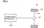
- Fig. 1 is a block diagram illustrating a schematic configuration of a hybrid vehicle 10 including a hybrid drive apparatus 100 according to an embodiment of the present invention. It is noted that hybrid drive apparatus 100 is shown as a typical example of a motor drive circuit including: a plurality of motors coupled to be capable of outputting motive power to a common output shaft; and a plurality of motor drive circuits connected to these plurality of motors, respectively.
- hybrid vehicle 10 includes hybrid drive apparatus 100, a differential gear 30, a drive shaft 40, and a drive wheel 50.
- Hybrid drive apparatus 100 has an engine (internal combustion engine) and two motor generators built therein, and generates an output by cooperative control of the engine and the motor generators.
- the output of hybrid drive apparatus 100 is transmitted to drive shaft 40 through differential gear 30 and is used for rotationally driving drive wheel 50.
- Differential gear 30 absorbs a difference in rotation between right and left drive wheels 50 by utilizing a difference in resistance from a road surface.
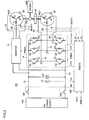
- Fig. 2 is a block diagram describing a configuration of hybrid drive apparatus 100 shown in Fig. 1 in detail.
- hybrid drive apparatus 100 includes an engine ENG such as an internal combustion engine operated by combustion of fuel, a spring-type damper device 114 for absorbing rotational fluctuations of engine ENG, a planetary gear-type power split device PSD for mechanically distributing the output of engine ENG transmitted through damper device 114 to a motor generator MG1 and an output member 118, and a motor generator MG2 for applying the rotational force to output member 118.
- engine ENG such as an internal combustion engine operated by combustion of fuel
- a spring-type damper device 114 for absorbing rotational fluctuations of engine ENG
- PSD planetary gear-type power split device
- motor generator MG2 for applying the rotational force to output member 118.
- Engine ENG, damper device 114, power split device PSD, and motor generator MG1 are axially arranged side by side on a common shaft, and motor generator MG2 is concentrically placed on the outer circumferential side of damper device 114 and power split device PSD.
- Power split device PSD is a single pinion-type planetary gear device, and includes a sun gear 120s coupled to a motor shaft 124 of motor generator MG1, a carrier 120c coupled to damper device 114, and a ring gear 120r coupled to rotor 122r of motor generator MG2, as three rotary elements.
- Output member 118 is integrally fixed to rotor 122r of motor generator MG2 by a bolt and the like, and is coupled to ring gear 120r of power split device PSD with rotor 122r interposed therebetween. Output member 118 is provided with an output gear wheel 126. Bevel gear-type differential gear 30 is slowed down and rotated by a main gear wheel 130 and a small gear wheel 132 of an intermediate shaft 128, to distribute motive power to drive wheel 50 shown in Fig. 1 .
- Output gear wheel 126 is provided with a parking lock brake mechanism (not shown) for locking an output from output member 118.
- the parking lock brake mechanism limits output of driving force from hybrid drive apparatus 100 by locking output gear wheel 126 when the driver selects a parking position (P position).
- Motor generator MG1 and motor generator MG2 are electrically connected to a DC power supply 140 with an inverter 14 and an inverter 31 interposed therebetween, respectively.
- motor generators MG1 and MG2 The operation of these motor generators MG1 and MG2 is switched among a rotationally driven state in which motor generators MG1 and MG2 are supplied with electric energy from DC power supply 140 and rotationally driven at prescribed torque, a charging state in which motor generators MG1 and MG2 function as generators to charge DC power supply 140 with electric energy as a result of rotational braking (electrical braking torque of the motor generators themselves), and a no-load state in which free rotation of motor shaft 124 and rotor 122r is allowed.
- An HVECU (Electronic Control Unit) 200 performs signal processing in accordance with a preset program to switch the traveling mode by motor generators MG1 and MG2 among the motor traveling, the charging traveling, the engine and motor traveling, and the like, depending on the driving conditions.
- motor generator MG1 In the motor traveling, for example, motor generator MG1 is set to the no-load state and motor generator MG2 is set to the rotationally driven state, and hybrid vehicle 10 travels by using only motor generator MG2 as a power source.
- motor generator MG1 functions as a generator and motor generator MG2 is set to the no-load state.
- DC power supply 140 is charged by motor generator MG1.
- motor generator MG1 functions as a generator, and while hybrid vehicle 10 travels by using both engine ENG and motor generator MG2 as power sources, DC power supply 140 is charged by motor generator MG1.
- HVECU 200 also exercises the regenerative braking control in which motor generator MG2 functions as a generator for regenerative braking at the time of the above motor traveling, the charging control in which motor generator MG1 functions as a generator and engine ENG is operated when the vehicle stops, and DC power supply 140 is charged entirely by motor generator MG1, and the like.
- HVECU 200 generates a torque command value for each of motor generators MG1 and MG2 such that desired driving force and electric power is generated in each traveling mode.
- engine ENG automatically stops when the vehicle stops, whereas the start timing thereof is controlled by HVECU 200, depending on the driving conditions.
- hybrid vehicle 10 travels by using the driving force generated by motor generator MG2 without starting engine ENG, in order to avoid a region in which engine efficiency is bad.
- engine ENG starts.
- engine ENG starts in the no-load state at the start of traveling, and is driven at the idling engine speed until the desired warm-up is implemented.
- engine ENG also starts when the above charging control is exercised at the time of parking of the vehicle.
- Fig. 3 is a circuit diagram illustrating an electrical configuration of hybrid drive apparatus 100 shown in Fig. 2 .
- hybrid drive apparatus 100 further includes DC power supply 140, a voltage sensor 13, system relays SRI and SR2, a smoothing capacitor C2, inverters 14 and 31, current sensors 24 and 28, position sensors 22 and 26, and an MGECU 300.
- DC power supply 140 is configured to include a power storage device (not shown) and outputs a DC voltage between a power supply line VL and a ground line SL.
- DC power supply 140 can be configured to convert an output voltage of a secondary battery and output the converted voltage to power supply line VL and ground line SL by a combination of the secondary battery and a step-up and down converter.
- the step-up and down converter is configured to allow bidirectional power conversion, and converts the DC voltage between power supply line VL and ground line SL to a charging voltage for the secondary battery.
- System relay SRI is connected between a positive electrode of DC power supply 140 and power supply line VL, and system relay SR2 is connected between a negative electrode of DC power supply 140 and ground line SL. System relays SRI and SR2 are turned on/off in response to a signal SE from MGECU 300.
- Smoothing capacitor C2 is connected between power supply line VL and ground line SL.
- Voltage sensor 13 detects a voltage Vm across smoothing capacitor C2 (which corresponds to an input voltage of inverters 14 and 31, and the same is applied in the following), and outputs voltage Vm to MGECU 300.
- Inverter 14 connected to motor generator MG1 includes a U-phase arm 15, a V-phase arm 16 and a W-phase arm 17.
- U-phase arm 15, V-phase arm 16 and W-phase arm 17 are provided in parallel between power supply line VL and ground line SL.
- U-phase arm 15 includes serially-connected power semiconductor switching elements (that will also be simply referred to as switching elements hereinafter) Q1 and Q2.
- V-phase arm 16 includes serially-connected switching elements Q3 and Q4.
- W-phase arm 17 includes serially-connected switching elements Q5 and Q6.
- diodes D1 to D6 causing current flow from the emitter side to the collector side are connected, respectively.
- An IGBT Insulated Gate Bipolar Transistor
- On/off that is, switching of switching elements Q1 to Q6 is controlled in response to a switching control signal PWMI1 from MGECU 300.
- each phase arm is connected to an end of each phase of each phase coil of motor generator MG1 via a conductive line (wire harness).
- motor generator MG1 is a three-phase permanent magnet motor, having three coils of U, V and W phases commonly connected at one end to the neutral point.
- the U-phase coil has its the other end connected to the midpoint between IGBT elements Q1 and Q2 via a conductive line 18, the V-phase coil has its the other end connected to the midpoint between IGBT elements Q3 and Q4 via a conductive line 19, and the W-phase coil has its the other end connected to the midpoint between IGBT elements Q5 and Q6 via a conductive line 20.
- Current sensor 24 is provided at each of conductive lines 18 to 20.
- Current sensor 24 detects a current MCRT1 flowing to motor generator MG1. It is noted that, since the sum of motor currents Iu, Iv and Iw (instantaneous values) of the U, V and W phases is zero, hybrid drive apparatus 100 may be configured such that current sensor 24 arranged at the two phases detects the motor current of each phase. Current value MCRT1 detected by current sensor 24 is delivered to MGECU 300.
- Position sensor 22 for detecting a rotation angle of a rotor (not shown) is further arranged at motor generator MG1. The rotation angle detected by position sensor 22 is delivered to MGECU 300.
- Inverter 31 connected to motor generator MG2 has a configuration similar to that of inverter 14.
- inverter 31 includes switching elements Q1 to Q6 and diodes D1 to D6. On/off (switching) of switching elements Q1 to Q6 is controlled in response to a switching control signal PWMI2 from MGECU 300.
- Motor generator MG2 is a three-phase permanent magnet motor, having three coils of the U, V and W phases commonly connected at one end to the neutral point, similarly to motor generator MG1.
- the midpoints of the respective phase arms of inverter 31 are electrically connected to the U-phase coil, the V-phase coil and the W-phase coil of motor generator MG2 via conductive lines, respectively.
- Current sensor 28 similar to current sensor 24 is provided at the conductive line connecting inverter 31 and each phase coil of motor generator MG2. Furthermore, position sensor 26 similar to position sensor 22 is also arranged at motor generator MG2. A current value MCRT2 detected by current sensor 28 and a value detected by the position sensor are delivered to MGECU 300.
- MGECU 300 receives an operation command for motor generator MG1 from not-shown HVECU 200.
- This operation command includes an instruction for permitting/prohibiting the operation of motor generator MG1, a torque command value TR1, a rotation speed command MRN1, and the like.
- MGECU 300 By feedback control based on the values detected by current sensor 24 and position sensor 22, MGECU 300 generates switching control signal PWMI1 for controlling the switching operation of switching elements Q1 to Q6 such that motor generator MG1 operates in accordance with the operation command from HVECU 200.
- MGECU 300 when HVECU 200 issues the operation command for motor generator MG1, MGECU 300 generates switching control signal PWMI1 for converting the DC voltage between power supply line VL and ground line SL to the AC voltage to be applied to each phase coil of motor generator MG1, such that the motor currents of the respective phases in accordance with torque command value TR1 of motor generator MG1 are supplied.
- switching control signal PWMI1 is generated by the feedback control in accordance with, for example, the well-known PWM control scheme, in which the values detected by the sensors are used.
- MGECU 300 when HVECU 200 issues the instruction for prohibiting the operation of motor generator MG1, MGECU 300 generates a switching control signal STP to stop (all OFF) the switching operation of each of switching elements Q1 to Q6 forming inverter 14.
- MGECU 300 when receiving an operation command for motor generator MG2 from HVECU200, MGECU 300 generates switching control signal PWMI2 for controlling the switching operation of switching elements Q1 to Q6 such that motor generator MG2 operates in accordance with the operation command from HVECU 200, by the feedback control based on the values detected by current sensor 28 and position sensor 26, similarly to the control over motor generator MG1 described above.
- HVECU 200 information about an abnormality in inverters 14 and 31 detected by MGECU 300 is delivered to HVECU 200.
- HVECU 200 is configured to be capable of reflecting this abnormality information in the operation commands for motor generators MG1 and MG2.
- motor generators MG1 and MG2 correspond to "a plurality of multiphase AC motors" in the present invention
- inverters 14 and 31 correspond to "a plurality of power converting devices” in the present invention
- MGECU 300 and HVECU 200 correspond to "controller” in the present invention.
- hybrid vehicle 10 configured as described above, when motor generator MG1 cannot be used because of the abnormality in inverter 14 connected to motor generator MG1, the operation of engine ENG and motor generator MG1 is stopped and "limp-home operation" of hybrid vehicle 10 can be performed by "abnormal state operation” in which motive power generated by motor generator MG2 is used, as is also described in Patent Document 1.
- motor generator MG1 rotates with the operation (rotation) of motor generator MG2, because motor generator MG1 and motor generator MG2 are coupled to each other with power split device PSD interposed therebetween.
- a magnet PM attached to the rotor rotates with the rotation of motor generator MG1 during the limp-home operation.
- an induced voltage is generated at each phase coil of motor generator MG1.
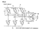
- Fig. 4 illustrates, as an example of a short-circuit fault in inverter 14, the case where a short-circuit fault in which a switching element is maintained in the ON state and goes out of control occurs in switching element Q1.
- U-phase motor current Iu is branched at the neutral point of motor generator MG1 to a route Rt1 extending from the V-phase coil through the midpoint of V-phase arm 16 and diode D3 to power supply line VL, and a route Rt2 extending from the W-phase coil through the midpoint of W-phase arm 17 and diode D5 to power supply line VL.
- Rt1 a route extending from the V-phase coil through the midpoint of V-phase arm 16 and diode D3 to power supply line VL
- Rt2 extending from the W-phase coil through the midpoint of W-phase arm 17 and diode D5 to power supply line VL.
- the induced voltage generated at each phase coil of motor generator MG1 is proportional to the rotation speed of motor generator MG1. Therefore, as the rotation speed of motor generator MG2 during the limp-home operation increases, the induced voltage generated at motor generator MG1 also becomes higher and the short-circuit current in inverter 14 also increases. The excessive short-circuit current may lead to the occurrence of further damage to the elements resulting from the generation of the high temperature exceeding the heat-resistant temperature of the components of inverter 14.
- the vehicle in Patent Document 1 as described above has a control configuration in which the level of the short-circuit current flowing through inverter 14 is monitored, and thereby limiting the limp-home operation using motor generator MG2 when the excessive short-circuit current flows through inverter 14. As a result, the occurrence of further damage to the elements within the inverter is prevented by performing the limp-home operation.
- hybrid drive apparatus 100 is configured such that switching of switching elements Q1 to Q6 forming inverter 14 is controlled in accordance with the rotation speed of motor generator MG1.
- switching of switching elements Q1 to Q6 forming inverter 14 is controlled in accordance with the rotation speed of motor generator MG1.
- a control structure for implementing the switching control of the inverter during the limp-home operation in hybrid drive apparatus 100 according to the present embodiment will be described hereinafter.
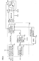
- Fig. 5 is a block diagram illustrating a control structure in MGECU 300 according to the embodiment of the present invention. Although each functional block shown in Fig. 5 is implemented typically by executing a program stored by MGECU 300 in advance, a part or all of the functions may be mounted as dedicated hardware.
- MGECU 300 includes, as means for controlling inverter 14, a motor control phase voltage calculating unit 32, an inverter drive signal converting unit 34, an inverter abnormality detecting unit 36, and a short-circuited element detecting unit 38. It is noted that, although not shown, MGECU 300 further includes means for controlling inverter 31 having a configuration similar to that in Fig. 5 .
- Motor control phase voltage calculating unit 32 receives torque command value TR1 and rotation speed command MRN1 as the operation command for motor generator MG1 from HVECU 200, receives input voltage Vm of inverter 14 from voltage sensor 13, and receives motor currents Iu, Iv and Iw flowing to the respective phases of motor generator MG1 from current sensor 24. Based on these input signals, motor control phase voltage calculating unit 32 calculates voltage amounts (that will also be referred to as voltage commands hereinafter) Vu*, Vv* and Vw* to be applied to the respective phase coils of motor generator MG1, and outputs the result of the calculation to inverter drive signal converting unit 34.
- voltage amounts that will also be referred to as voltage commands hereinafter
- Inverter drive signal converting unit 34 generates switching control signal PWMI1 for actually turning on/off switching elements Q1 to Q6 of inverter 14, based on voltage commands Vu*, Vv* and Vw* of the respective phase coils from motor control phase voltage calculating unit 32, and delivers generated switching control signal PWMI1 to inverter 14.
- Inverter abnormality detecting unit 36 senses an abnormality that has occurred in inverter 14 during the operation of motor generator MG1.
- the abnormality in inverter 14 is sensed based on an overcurrent sense signal OVC from self-protection circuits built into switching elements Q1 to Q6 of inverter 14.
- the self-protection circuit is configured to include a current sensor (or a temperature sensor), and outputs overcurrent sense signal OVC in response to the overcurrent (or overheating) detected in a sensor output.
- a current sensor or a temperature sensor
- OVC overcurrent sense signal
- inverter abnormality detecting unit 36 determines that the abnormality occurs due to the short-circuit fault in switching elements Q1 to Q6, and generates an abnormality signal FINV indicating the result of the determination. Then, inverter abnormality detecting unit 36 delivers generated abnormality signal FINV to HVECU 200 and short-circuited element detecting unit 38.
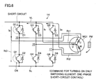
- HVECU 200 When receiving abnormality signal FINV, HVECU 200 instructs the limp-home operation using motor generator MG2. At this time, HVECU 200 issues an instruction for stopping the switching operation of switching elements Q1 to Q6 forming inverter 14 to inverter drive signal converting unit 34.
- inverter drive signal converting unit 34 In response to this, inverter drive signal converting unit 34 generates switching control signal STP for stopping (OFF state) the switching operation of switching elements Q1 to Q6, and outputs generated switching control signal STP to inverter 14. As a result, inverter 14 is set to a suspended state.
- short-circuited element detecting unit 38 When receiving abnormality signal FINV from inverter abnormality detecting unit 36, short-circuited element detecting unit 38 detects a short-circuited switching element from the inverter where the abnormality has occurred, based on current values Iu, Iv and Iw of the respective phases between inverter 14 and motor generator MG1 that are detected by current sensor 24. As an example, short-circuited element detecting unit 38 detects a value offset from that obtained at the time of the steady operation, for each of the current waveforms of motor currents Iu, Iv and Iw, and detects the short-circuited switching element based on the magnitude and the polarity of the detected offset value. Then, short-circuited element detecting unit 38 generates a signal DE indicating the short-circuited switching element that has been detected, and delivers signal DE to inverter drive signal converting unit 34.
- inverter drive signal converting unit 34 When receiving signal DE from short-circuited element detecting unit 38, inverter drive signal converting unit 34 generates any one of a switching control signal Ton1 and a switching control signal Ton2, in accordance with a rotation speed Nmg1 of motor generator MG1 derived from the value detected by position sensor 22.
- switching control signal Ton1 is a signal for controlling the switching operation to turn on only a switching element connected in series to the short-circuited switching element among switching elements Q1 to Q6 forming inverter 14.
- Ton1 is a signal for controlling the switching operation to turn on only a switching element connected in series to the short-circuited switching element among switching elements Q1 to Q6 forming inverter 14.
- switching control signal Ton2 is a signal for controlling the switching operation to turn on all switching elements connected in parallel to the short-circuited switching element in the power supply line (or ground line) among switching elements Q1 to Q6 forming inverter 14.
- Ton2 is a signal for controlling the switching operation to turn on all switching elements connected in parallel to the short-circuited switching element in the power supply line (or ground line) among switching elements Q1 to Q6 forming inverter 14.
- the switching control for turning on the switching elements connected in parallel to the short-circuited switching element in the power supply line as described above will also be simply referred to as "three-phase ON control" hereinafter.
- Inverter drive signal converting unit 34 switches between and exercises the one-phase short-circuit control and the three-phase ON control, in accordance with rotation speed Nmg1 of motor generator MG1 derived from the value detected by position sensor 22. The details of each switching control will be described hereinafter.
- Fig. 6 is a diagram describing the short-circuit current within the inverter generated when the one-phase short-circuit control is exercised.
- motor currents Iu, Iv and Iw of the respective phases show AC waveforms having substantially the same amplitude, similarly to the waveform during the normal operation of motor generator MG1. It is noted that the amplitude of the motor currents of the respective phases becomes larger by increasing the rotation speed of motor generator MG1, as will be described hereinafter.
- Fig. 7 is a diagram describing the short-circuit current within the inverter generated when the three-phase ON control is exercised.
- Fig. 8 illustrates output waveforms of the motor currents generated when the three-phase ON control is exercised. It is noted that the output waveforms in Fig. 8 are obtained by simulating motor currents Iu, Iv and Iw induced when motor generator MG1 is rotated at a prescribed rotation speed in the circuit configuration shown in Fig. 7 .
- motor currents Iu, Iv and Iw show the AC waveforms having substantially the same amplitude. As will be described hereinafter, it is obtained from the result of the simulation that the amplitude of the motor currents hardly changes even if the rotation speed of motor generator MG1 is increased.
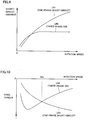
- Fig. 9 illustrates the relationship between the rotation speed of motor generator MG1 and the short-circuit currents within the inverter generated when the one-phase short-circuit control and the three-phase ON control are exercised.
- the relationship shown in Fig. 9 is obtained by simulating motor currents Iu, Iv and Iw that, when motor generator MG1 is rotated at various rotation speeds, is induced at each of the rotation speeds, in the circuit configurations shown in Figs. 6 and 7 .
- a line LN1 indicates the short-circuit current generated when the one-phase short-circuit control is exercised
- a line LN2 indicates the short-circuit current generated when the three-phase ON control is exercised.
- the braking torque is generated by the rotation of motor generator MG1 with the rotation of motor generator MG2.
- This braking torque acts on the vehicle based on the rotational resistance of motor generator MG1, and therefore, it is also referred to as "drag torque.”
- drag torque The relationship as shown in Fig. 10 is established between this drag torque and the rotation speed of motor generator MG1.
- Fig. 10 illustrates the relationship between the rotation speed of motor generator MG1 and the drag torque generated at motor generator MG1 when the one-phase short-circuit control and the three-phase ON control are exercised.
- the relationship shown in Fig. 10 is obtained by using the magnetic field analysis to simulate the drag torque generated at motor generator MG1 when the short-circuit current in Fig. 9 is flowing, for each of the one-phase short-circuit control and the three-phase ON control. It is noted that the drag torque is indicated by a negative value in order to distinguish the drag torque from torque generated during power running control over motor generator MG1.
- a line LN3 indicates the drag toque generated when the one-phase short-circuit control is exercised
- a line LN4 indicates the drag torque generated when the three-phase ON control is exercised.
- the characteristic of the drag torque generated when the one-phase short-circuit control is exercised is different from that of the drag torque generated when the three-phase ON control is exercised, and the magnitude relationship is inverted with a prescribed reference rotation speed Nth in the figure being a boundary.
- the drag torque increases as compared to that generated when the one-phase short-circuit control is exercised.
- the drag torque exceeds the torque generated by motor generator MG2, and therefore, the drivability may be lowered.
- the drag torque can be suppressed, regardless of the rotation speed of motor generator MG1.
- the generation of the excessive short-circuit current can be prevented in the rotation speed region that is higher than prescribed reference rotation speed Nth.
- inverter drive signal converting unit 34 when inverter drive signal converting unit 34 receives signal DE from short-circuited element detecting unit 38, inverter drive signal converting unit 34 derives rotation speed Nmg1 of motor generator MG1 from the value detected by position sensor 22, and determines whether or not derived rotation speed Nmg1 exceeds prescribed reference rotation speed Nth. At this time, when rotation speed Nmg1 is less than or equal to prescribed reference rotation speed Nth, inverter drive signal converting unit 34 generates switching control signal Ton1 for exercising the one-phase short-circuit control. On the other hand, when rotation speed Nmg1 exceeds prescribed reference rotation speed Nth, inverter drive signal converting unit 34 generates switching control signal Ton2 for exercising the three-phase ON control. It is noted that prescribed reference rotation speed Nth can be determined in advance by simulating the relationship shown in Fig. 10 .
- Fig. 11 is a flowchart describing the limp-home operation when MG1 in the hybrid drive apparatus according to the embodiment of the present invention is abnormal. It is noted that the process in each step shown in Fig. 11 is implemented by MGECU 300 and HVECU 200 functioning as each functional block shown in Fig. 5 .
- MGECU 300 functioning as inverter abnormality detecting unit 36 determines whether or not the abnormality is occurring in inverter 14 connected to motor generator MG1 (step S01). At this time, MGECU 300 determines whether or not MGECU 300 receives overcurrent sense signal OCV from the self-protection circuits built into switching elements Q1 to Q6. If MGECU 300 does not receive overcurrent sense signal OCV from inverter 14, MGECU 300 determines that the abnormality is not occurring in inverter 14 (NO determination in step S01), and MGECU 300 does not instruct the limp-home operation (step S02), and ends the control process related to the limp-home operation.
- MGECU 300 determines that the abnormality is occurring in inverter 14 (YES determination in step S01) and issues abnormality signal FINV As a result, HVECU 200 instructs the limp-home operation using motor generator MG2 (step S03). At this time, HVECU 200 issues the instruction for stopping the switching operation of each of switching elements Q1 to Q6 forming inverter 14. In response to this, switching control signal PWMI1 from MGECU 300 is set to the OFF state.
- MGECU 300 functioning as short-circuited element detecting unit 38 receives abnormality signal FINV, MGECU 300 detects the short-circuited switching element from the inverter where the abnormality has occurred, based on current values Iu, Iv and Iw of the respective phases between inverter 14 and motor generator MG1 that are detected by current sensor 24 (step S04). Then, MGECU 300 functioning as short-circuited element detecting unit 38 generates signal DE indicating the short-circuited switching element that has been detected, and delivers signal DE to MGECU 300 functioning as inverter drive signal converting unit 34.
- MGECU 300 functioning as inverter drive signal converting unit 34 receives signal DE from short-circuited element detecting unit 38, MGECU 300 obtains rotation speed Nmg1 of motor generator MG1 based on the value detected by position sensor 22 (step S05). Then, MGECU 300 functioning as inverter drive signal converting unit 34 determines whether or not rotation speed Nmg1 exceeds prescribed reference rotation speed Nth (step S06).
- MGECU 300 functioning as inverter drive signal converting unit 34 exercises the three-phase ON control (step S07). Specifically, MGECU 300 generates switching control signal Ton2 and outputs switching control signal Ton2 to switching elements Q1 to Q6 forming inverter 14. As a result, all of the switching elements connected in parallel to the short-circuited switching element in the power supply line (or ground line) are turned on.
- MGECU 300 functioning as inverter drive signal converting unit 34 exercises the one-phase short-circuit control (step S08). Specifically, MGECU 300 generates switching control signal Ton1 and outputs switching control signal Ton1 to switching elements Q1 to Q6 forming inverter 14. As a result, the switching element connected in series to the short-circuited switching element is turned on.
- MGECU 300 functioning as inverter drive signal converting unit 34 determines whether or not the limp-home operation using motor generator MG2 continues (step S09). If the limp-home operation continues (YES in step S09), the process is returned to step S05.
- MGECU 300 ends the control process related to the limp-home operation.
- the drag torque generated at motor generator MG1 with the rotation of motor generator MG2 can be made small when the rotation speed of motor generator MG2 during the limp-home operation is low.
- the drag torque exceeds the torque generated by motor generator MG2, and lowering of the drivability can be suppressed.
- the limp-home operation using motor generator MG2 is performed when the abnormality occurs in inverter 14 serving as the power converting device connected to motor generator MG1
- the limp-home operation using engine ENG and motor generator MG1 is also performed by performing the process similar to the flowchart shown in Fig. 11 , when the abnormality occurs in inverter 31 serving as the power converting device connected to motor generator MG2.
- the distance traveled during the limp-home operation can be extended while the excessive short-circuit current flowing through inverter 31 is prevented.
- the motor drive apparatus in the hybrid vehicle including the two motors coupled to each other by the power split device has been described as an example in the present embodiment, application of the present invention is not limited to such a type.
- the present invention is also applicable to any type of hybrid drive apparatus such as a so-called electric power distribution-type apparatus, and a motor drive apparatus other than the hybrid drive apparatus configured to include the plurality of motors, as long as the apparatus is configured such that one motor is operated and another motor is rotated with the operation of the one motor during the limp-home operation.
- the present invention is applicable to a motor drive apparatus and a hybrid drive apparatus configured to include a plurality of motors coupled to be capable of outputting motive power to a common output shaft.
Claims (6)
- Appareil d'entraînement de moteur, comprenant :une pluralité de moteurs à CA multiphasé (MG1, MG2) couplés pour être capables de délivrer en sortie une force motrice à un arbre de sortie commun ;une pluralité de dispositifs de conversion de puissance (14, 31) connectés à ladite pluralité de moteurs à CA multiphasé (MG1, MG2), respectivement ; etun dispositif de commande (300) pour commander ladite pluralité de dispositifs de conversion de puissance (14, 31),chacun de ladite pluralité de dispositifs de conversion de puissance (14, 31) incluant une pluralité de circuits de bras (15, 16, 17) connectés à des bobines de phase respectives dudit moteur à CA multiphasé, etchacun de ladite pluralité de circuits de bras (15, 16, 17) comportant des premier et second éléments de commutation connectés en série entre des première et seconde lignes d'alimentation électrique (VL, SL) avec un point de connexion à une dite chaque bobine de phase interposée, etledit dispositif de commande (300) incluantun moyen de commande d'anomalie qui est configuré pour, lorsqu'un premier dispositif de conversion de puissance (14) parmi ladite pluralité de dispositifs de conversion de puissance (14, 31) est anormal ce qui signifie que le premier dispositif de conversion de puissance (14) présente un défaut de court-circuit dans lequel un élément de commutation est maintenu dans un état EN MARCHE, ordonner une opération d'état anormal en utilisant un second moteur à CA multiphasé (MG2) différent d'un premier moteur à CA multiphasé (MG1) connecté audit premier dispositif de conversion de puissance (14),un moyen de détection de court-circuit configuré pour détecter un élément de commutation court-circuité sur la base d'un courant circulant à travers ledit premier dispositif de conversion de puissance (14) en résultat de l'opération dudit second moteur à CA multiphasé (MG2), dans ladite opération d'état anormal,un premier moyen de commande de moteur configuré pour commander le courant circulant à travers ledit premier dispositif de conversion de puissance (14) en amenant en conduction un élément de commutation connecté en série audit élément de commutation court-circuité avec ledit point de connexion interposé, dans ladite opération d'état anormal,un deuxième moyen de commande de moteur configuré pour commander le courant circulant à travers ledit premier dispositif de conversion de puissance (14) en amenant en conduction tous les éléments de commutation connectés en parallèle audit élément de commutation court-circuité dans l'une quelconque des première et seconde lignes d'alimentation électrique (VL, SL) dans lesquelles l'élément de commutation de court-circuit est connecté, dans ladite opération d'état anormal, etun moyen de sélection configuré pour régler sélectivement ledit premier moyen de commande de moteur et ledit deuxième moyen de commande de moteur en fonction d'une vitesse de rotation dudit premier moteur à CA multiphasé (MG1), dans lequel ledit moyen de sélection est configuré pour sélectionner ledit premier moyen de commande de moteur lorsque la vitesse de rotation dudit premier moteur à CA multiphasé (MG1) est inférieure ou égale à une vitesse de rotation de référence prescrite, et pour sélectionner ledit deuxième moyen de commande de moteur lorsque la vitesse de rotation dudit premier moteur à CA multiphasé (MG1) dépasse ladite vitesse de rotation de référence prescrite.
- Appareil d'entraînement de moteur selon la revendication 1, dans lequel
lorsque ledit premier moyen de commande de moteur est exécuté, ledit premier moteur à CA multiphasé (MG1) présente une première caractéristique telle que le couple de freinage généré en résultat de l'opération dudit second moteur à CA multiphasé (MG2) devient plus grand à mesure que la vitesse de rotation dudit premier moteur à CA multiphasé (MG1) augmente,
lorsque ledit deuxième moyen de commande de moteur est exécuté, ledit premier moteur à CA multiphasé (MG1) présente une seconde caractéristique telle que le couple de freinage généré en résultat de l'opération dudit second moteur à CA multiphasé (MG2) devient plus petit à mesure que la vitesse de rotation dudit premier moteur à CA multiphasé (MG1) augmente, et
ledit moyen de sélection présente des première et seconde caractéristiques à l'avance, et est configuré pour régler, à ladite vitesse de rotation de référence prescrite, la vitesse de rotation dudit premier moteur à CA multiphasé (MG1) lorsque le couple de freinage généré au niveau dudit premier moteur à CA multiphasé présentant ladite première caractéristique correspond à celui généré au niveau dudit premier moteur à CA multiphasé présentant ladite seconde caractéristique. - Appareil d'entraînement hybride, comprenant :un moteur à combustible (ENG) actionné par combustible ;un premier moteur générateur (MG1) ;un organe de sortie (118) pour délivrer en sortie une force motrice ;un dispositif de répartition de puissance (PSD) couplant ledit organe de sortie (118), un arbre de sortie dudit moteur à combustible (ENG) et un arbre de sortie dudit premier moteur générateur (MG1) les uns aux autres ;un second moteur générateur (MG2) couplé audit organe de sortie (118) ;un premier onduleur (14) connecté entre une alimentation électrique CC (140) et ledit premier moteur générateur (MG1), pour la commande d'entraînement dudit premier moteur générateur (MG1) ;un second onduleur (31) connecté entre ladite alimentation électrique CC (140) et ledit second moteur générateur (MG2), pour la commande d'entraînement dudit second moteur générateur (MG2) ; etun dispositif de commande (300) pour commander l'opération desdits premier et second moteurs générateurs (MG1, MG2),ledit premier onduleur (14) incluant une pluralité de premiers circuits de bras (15, 16, 17) connectés à des bobines de phase respectives dudit premier moteur générateur (MG1),ledit second onduleur (31) incluant une pluralité de seconds circuits de bras (15, 16, 17) connectés à des bobines de phase respectives dudit second moteur générateur (MG2), etchacun de ladite pluralité de premiers et seconds circuits de bras (15, 16, 17) comportant des premier et second éléments de commutation connectés en série entre les première et seconde lignes d'alimentation électrique (VL, SL) avec un point de connexion à une dite chaque bobine de phase interposée, etledit dispositif de commande (300) incluantun moyen de commande d'anomalie configuré pour ordonner une opération d'état anormal en utilisant ledit second moteur générateur (MG2), lorsque ledit premier onduleur (14) est anormal ce qui signifie que le premier onduleur (14) présente un défaut de court-circuit dans lequel un élément de commutation est maintenu dans un état EN MARCHE,un moyen de détection de court-circuit pour détecter un élément de commutation court-circuité sur la base d'un courant circulant à travers ledit premier onduleur (14) en résultat de l'opération dudit second moteur générateur (MG2), dans ladite opération d'état anormal,un premier moyen de commande de moteur configuré pour commander le courant circulant à travers ledit premier onduleur (14) en amenant en conduction un élément de commutation connecté en série audit élément de commutation court-circuité avec ledit point de connexion interposé, dans ladite opération d'état anormal,un deuxième moyen de commande de moteur configuré pour commander le courant circulant à travers ledit premier onduleur (14) en amenant en conduction tous les éléments de commutation connectés en parallèle audit élément de commutation court-circuité dans l'une quelconque des première et seconde lignes d'alimentation électrique (VL, SL) dans lesquelles l'élément de commutation de court-circuit est connecté, dans ladite opération d'état anormal, etun premier moyen de sélection configuré pour régler sélectivement ledit premier moyen de commande de moteur et ledit deuxième moyen de commande de moteur en fonction d'une vitesse de rotation dudit premier moteur générateur (MG1), dans lequel ledit premier moyen de sélection est configuré pour sélectionner ledit premier moyen de commande de moteur lorsque la vitesse de rotation dudit premier moteur générateur (MG1) est inférieure ou égale à une vitesse de rotation de référence prescrite, et pour sélectionner ledit deuxième moyen de commande de moteur lorsque la vitesse de rotation dudit premier moteur générateur (MG1) dépasse ladite vitesse de rotation de référence prescrite.
- Appareil d'entraînement hybride selon la revendication 3, dans lequel
ledit moyen de commande d'anomalie est configuré pour ordonner l'opération d'état anormal en utilisant ledit moteur à combustible (ENG) et ledit premier moteur générateur (MG1), lorsque ledit second onduleur (31) est anormal,
ledit moyen de détection de court-circuit est configuré pour détecter l'élément de commutation court-circuité sur la base d'un courant circulant à travers ledit second onduleur (31) en résultat de l'opération dudit premier moteur générateur (MG1), dans ladite opération d'état anormal, et
ledit dispositif de commande (300) inclut en outre
un troisième moyen de commande de moteur configuré pour commander le courant circulant à travers ledit second onduleur (31) en amenant en conduction l'élément de commutation connecté en série audit élément de commutation court-circuité avec ledit point de connexion interposé, dans ladite opération d'état anormal,
un quatrième moyen de commande de moteur configuré pour commander le courant circulant à travers ledit second onduleur (31) en amenant en conduction tous les éléments de commutation connectés en parallèle audit élément de commutation court-circuité dans la ligne d'alimentation électrique, dans ladite opération d'état anormal, et
un second moyen de sélection configuré pour régler sélectivement ledit troisième moyen de commande de moteur et ledit quatrième moyen de commande de moteur en fonction d'une vitesse de rotation dudit second moteur générateur (MG2). - Appareil d'entraînement hybride selon la revendication 4, dans lequel
ledit second moyen de sélection est configuré pour sélectionner ledit troisième moyen de commande de moteur lorsque la vitesse de rotation dudit second moteur générateur (MG2) est inférieure ou égale à une vitesse de rotation de référence prescrite, et pour sélectionner ledit quatrième moyen de commande de moteur lorsque la vitesse de rotation dudit second moteur générateur (MG2) dépasse ladite vitesse de rotation de référence prescrite. - Procédé de commande d'un appareil d'entraînement de moteur incluant une pluralité de moteurs à CA multiphasé (MG1, MG2) couplés pour être capables de délivrer en sortie une force motrice à un arbre de sortie commun et une pluralité de dispositifs de conversion de puissance (14, 31) connectée à ladite pluralité de moteurs à CA multiphasé (MG1, MG2), respectivement,
chacun de ladite pluralité de dispositifs de conversion de puissance (14, 31) incluant une pluralité de circuits de bras (15, 16, 17) connectés à des bobines de phase respectives dudit moteur à CA multiphasé,
chacun de ladite pluralité de circuits de bras (15, 16, 17) comportant des premier et second éléments de commutation connectés en série entre les première et seconde lignes d'alimentation électrique (VL, SL) avec un point de connexion à une dite chaque bobine de phase interposée, et
ledit procédé de commande comprenant les étapes de :ordonner une opération d'état anormal en utilisant un second moteur à CA multiphasé (MG2) différent d'un premier moteur à CA multiphasé (MG1) connecté à un premier dispositif de conversion de puissance (14) parmi ladite pluralité de dispositifs de conversion de puissance (14, 31), lorsque ledit premier dispositif de conversion de puissance (14) est anormal ce qui signifie que le premier dispositif de conversion de puissance (14) présente un défaut de court-circuit dans lequel un élément de commutation est maintenu dans un état EN MARCHE ;détecter un élément de commutation court-circuité sur la base d'un courant circulant à travers ledit premier dispositif de conversion de puissance (14) en résultat de l'opération dudit second moteur à CA multiphasé (MG2), dans ladite opération d'état anormal ;commander le courant circulant à travers ledit premier dispositif de conversion de puissance (14) en amenant en conduction un élément de commutation connecté en série audit élément de commutation court-circuité avec ledit point de connexion interposé, dans ladite opération d'état anormal ;commander le courant circulant à travers ledit premier dispositif de conversion de puissance (14) en amenant en conduction tous les éléments de commutation connectés en parallèle audit élément de commutation court-circuité dans l'une quelconque des première et seconde lignes d'alimentation électrique (VL, SL) dans lesquelles l'élément de commutation de court-circuit est connecté, dans ladite opération d'état anormal ; eten fonction d'une vitesse de rotation dudit premier moteur à CA multiphasé (MG1), régler sélectivement l'étape de commander le courant circulant à travers ledit premier dispositif de conversion de puissance (14) en amenant en conduction l'élément de commutation connecté en série audit élément de commutation court-circuité avec ledit point de connexion interposé, et l'étape de commander le courant circulant à travers ledit premier dispositif de conversion de puissance (14) en amenant en conduction tous les éléments de commutation connectés en parallèle audit élément de commutation court-circuité dans ladite ligne d'alimentation électrique,dans lequelladite étape de régler sélectivement sélectionne l'étape de commander le courant circulant à travers ledit premier dispositif de conversion de puissance (14) en amenant en conduction l'élément de commutation connecté en série audit élément de commutation court-circuité avec ledit point de connexion interposé, lorsque la vitesse de rotation dudit premier moteur à CA multiphasé (MG1) est inférieure ou égale à une vitesse de rotation de référence prescrite, et sélectionne l'étape de commande du courant circulant à travers ledit premier dispositif de conversion de puissance (14) en amenant en conduction tous les éléments de commutation connectés en parallèle audit élément de commutation court-circuité dans ladite ligne d'alimentation électrique, lorsque la vitesse de rotation dudit premier moteur à CA multiphasé (MG1) dépasse ladite vitesse de rotation de référence prescrite.
Applications Claiming Priority (2)
| Application Number | Priority Date | Filing Date | Title |
|---|---|---|---|
| JP2008033426A JP4240149B1 (ja) | 2008-02-14 | 2008-02-14 | モータ駆動装置およびハイブリッド駆動装置 |
| PCT/JP2008/068538 WO2009101729A1 (fr) | 2008-02-14 | 2008-10-14 | Appareil d'entraînement de moteur, appareil d'entraînement hybride et procédé de commande d'appareil d'entraînement de moteur |
Publications (3)
| Publication Number | Publication Date |
|---|---|
| EP2244370A1 EP2244370A1 (fr) | 2010-10-27 |
| EP2244370A4 EP2244370A4 (fr) | 2017-07-19 |
| EP2244370B1 true EP2244370B1 (fr) | 2019-10-09 |
Family
ID=40559902
Family Applications (1)
| Application Number | Title | Priority Date | Filing Date |
|---|---|---|---|
| EP08872356.4A Active EP2244370B1 (fr) | 2008-02-14 | 2008-10-14 | Appareil d'entraînement de moteur, appareil d'entraînement hybride et procédé de commande d'appareil d'entraînement de moteur |
Country Status (5)
| Country | Link |
|---|---|
| US (1) | US8040081B2 (fr) |
| EP (1) | EP2244370B1 (fr) |
| JP (1) | JP4240149B1 (fr) |
| CN (1) | CN101946397B (fr) |
| WO (1) | WO2009101729A1 (fr) |
Families Citing this family (56)
| Publication number | Priority date | Publication date | Assignee | Title |
|---|---|---|---|---|
| JP4747968B2 (ja) * | 2006-06-30 | 2011-08-17 | トヨタ自動車株式会社 | モータ駆動装置 |
| CN101911462B (zh) * | 2008-01-10 | 2014-03-19 | 三菱电机株式会社 | 功率转换装置 |
| JP5075034B2 (ja) * | 2008-07-02 | 2012-11-14 | トヨタ自動車株式会社 | ハイブリッド車両の退避走行制御装置 |
| JP5104647B2 (ja) * | 2008-08-20 | 2012-12-19 | トヨタ自動車株式会社 | ハイブリッド自動車の制御装置及び制御方法 |
| JP5334678B2 (ja) * | 2009-05-14 | 2013-11-06 | トヨタ自動車株式会社 | 車両駆動システムの制御装置 |
| JP5527883B2 (ja) * | 2009-12-08 | 2014-06-25 | 住友建機株式会社 | 建設機械 |
| JP5083305B2 (ja) * | 2009-12-24 | 2012-11-28 | 株式会社デンソー | 電動機駆動装置、および、これを用いた電動パワーステアリング装置 |
| US8374009B2 (en) * | 2010-03-25 | 2013-02-12 | Hamilton Sundstrand Corporation | Multi-level parallel phase converter |
| JP5168307B2 (ja) * | 2010-04-07 | 2013-03-21 | 株式会社デンソー | 電動機制御装置 |
| JP2011234517A (ja) * | 2010-04-28 | 2011-11-17 | Renesas Electronics Corp | 動力駆動制御装置および動力装置 |
| JP5170192B2 (ja) * | 2010-09-17 | 2013-03-27 | 株式会社デンソー | 回転機の制御装置 |
| JP5201245B2 (ja) * | 2010-09-17 | 2013-06-05 | 株式会社デンソー | 回転機の制御装置 |
| JP5488924B2 (ja) * | 2010-11-16 | 2014-05-14 | 株式会社デンソー | 車両のモータ制御装置 |
| DE102010053624A1 (de) * | 2010-12-07 | 2012-06-14 | Sew-Eurodrive Gmbh & Co. Kg | Fahrzeug und Verfahren zum Betreiben eines Fahrzeugs |
| US8976551B2 (en) * | 2010-12-07 | 2015-03-10 | Hitachi Automotive Systems, Ltd. | Power converter |
| JP5352570B2 (ja) * | 2010-12-13 | 2013-11-27 | 株式会社日立製作所 | 回転機の制御装置,回転機系,車両,電気自動車または発電システム |
| CN103282256A (zh) * | 2010-12-27 | 2013-09-04 | 丰田自动车株式会社 | 混合动力车辆及其控制方法 |
| US8810189B2 (en) * | 2011-02-25 | 2014-08-19 | Deere & Company | Machine systems including pre-power diagnostics |
| ITTO20110213A1 (it) * | 2011-03-10 | 2012-09-11 | Gate Srl | Dispositivo e procedimento di regolazione di tensione per motori elettrici in corrente continua, in particolare per elettroventilatori |
| DE102011075869A1 (de) * | 2011-05-16 | 2012-11-22 | Robert Bosch Gmbh | Verfahren und Steuergerät zur Erkennung einer geblockten Elektromaschine in einem Elektrofahrzeug |
| JP5626468B2 (ja) * | 2011-07-12 | 2014-11-19 | トヨタ自動車株式会社 | 車両および車両の制御方法 |
| DE102011085657A1 (de) * | 2011-11-03 | 2013-05-08 | Robert Bosch Gmbh | Verfahren und Vorrichtung zum Betreiben einer elektronisch kommutierten elektrischen Maschine in einem Fehlerfall |
| JP5985178B2 (ja) * | 2011-11-24 | 2016-09-06 | Ntn株式会社 | モータの制御装置 |
| JP5449429B2 (ja) | 2012-02-24 | 2014-03-19 | 三菱電機株式会社 | 交流回転機の制御装置及びその方法、電動パワーステアリング装置 |
| JP5974548B2 (ja) * | 2012-03-05 | 2016-08-23 | 富士電機株式会社 | 半導体装置 |
| US9302588B2 (en) * | 2012-06-29 | 2016-04-05 | Ford Global Technologies, Llc | Vehicle system for evaluating a voltage converter |
| US9933049B2 (en) * | 2012-10-04 | 2018-04-03 | Means Industries, Inc. | Vehicle drive system including a transmission |
| CN102874249B (zh) * | 2012-10-26 | 2015-11-18 | 潍柴动力股份有限公司 | 一种用于混合动力的电机控制装置 |
| DE102012224336A1 (de) * | 2012-12-21 | 2014-06-26 | Ge Energy Power Conversion Gmbh | Verfahren zum Betreiben eines elektrischen Stromrichters sowie elektrischer Stromrichter |
| DE102013103698A1 (de) * | 2013-04-12 | 2014-10-16 | Zf Lenksysteme Gmbh | Endstufenansteuerung im störfall |
| CN104167978A (zh) * | 2013-05-20 | 2014-11-26 | 安川电机(中国)有限公司 | 马达控制装置和马达驱动系统 |
| CN105493395B (zh) * | 2013-08-07 | 2018-04-13 | 株式会社东芝 | 车辆用控制装置以及铁路车辆 |
| JP2015082943A (ja) * | 2013-10-24 | 2015-04-27 | トヨタ自動車株式会社 | 車両制御装置 |
| JP6056734B2 (ja) * | 2013-10-25 | 2017-01-11 | トヨタ自動車株式会社 | 車両制御装置 |
| JP6220696B2 (ja) * | 2014-02-19 | 2017-10-25 | 日立オートモティブシステムズ株式会社 | 電動モータの駆動制御装置 |
| JP6362349B2 (ja) | 2014-02-19 | 2018-07-25 | 日立オートモティブシステムズ株式会社 | 電動モータの駆動制御装置 |
| AT515415B1 (de) | 2014-10-30 | 2015-09-15 | Ge Jenbacher Gmbh & Co Og | Verfahren zum Betreiben einer Brennkraftmaschine |
| JP2016097699A (ja) * | 2014-11-18 | 2016-05-30 | トヨタ自動車株式会社 | 自動車 |
| KR101494780B1 (ko) | 2014-11-27 | 2015-02-23 | 국방과학연구소 | 무인항공기의 전기식 구동장치와 그것의 제어방법 |
| JP6119778B2 (ja) | 2015-02-24 | 2017-04-26 | トヨタ自動車株式会社 | インバータの制御装置 |
| DE102015213304A1 (de) * | 2015-04-30 | 2016-11-03 | Thyssenkrupp Ag | Elektromechanische Servolenkung |
| EP3131198B1 (fr) * | 2015-08-10 | 2022-06-08 | Goodrich Actuation Systems Limited | Stratégie de commande d'un moteur double voie à aimant permanent à tolérance de pannes pour réduire le couple de traînée sous condition de défaillance |
| JP6365502B2 (ja) * | 2015-10-21 | 2018-08-01 | トヨタ自動車株式会社 | ハイブリッド車両 |
| US20170194882A1 (en) * | 2016-01-05 | 2017-07-06 | ZEROTECH (Chongqing) Intelligence Technology Co., Ltd. | Platform motor driving module, platform controlling system, and platform system |
| JP6418196B2 (ja) * | 2016-04-15 | 2018-11-07 | トヨタ自動車株式会社 | 電気自動車 |
| EP3266643A1 (fr) * | 2016-07-06 | 2018-01-10 | Volvo Car Corporation | Contrôleur de couple de dissipation d'énergie |
| JP2018085891A (ja) * | 2016-11-25 | 2018-05-31 | パナソニックIpマネジメント株式会社 | モータ駆動装置、及びモータ駆動装置の制御装置 |
| JP6944657B2 (ja) * | 2017-09-14 | 2021-10-06 | 日本精工株式会社 | モータ制御装置及びそれを搭載した電動パワーステアリング装置 |
| JP7003863B2 (ja) * | 2018-07-20 | 2022-02-04 | トヨタ自動車株式会社 | 車両の制御装置、制御方法および制御プログラム |
| TWI666460B (zh) * | 2018-08-10 | 2019-07-21 | 東元電機股份有限公司 | 馬達層間短路快篩方法 |
| CN109278561B (zh) * | 2018-11-22 | 2021-10-12 | 科力远混合动力技术有限公司 | 双电机功率分流式混合动力汽车电机故障处理控制方法 |
| JP7102053B2 (ja) * | 2018-12-05 | 2022-07-19 | 日立建機株式会社 | 回生制動システム、及び、それを用いた電気駆動作業車両 |
| KR20220023912A (ko) * | 2020-08-21 | 2022-03-03 | 현대자동차주식회사 | 하이브리드 차량의 고장 감지 방법 |
| JP2022080187A (ja) * | 2020-11-17 | 2022-05-27 | 株式会社Soken | 電力変換装置及び電力変換システム |
| US11575330B1 (en) * | 2021-07-29 | 2023-02-07 | Rivian Ip Holdings, Llc | Dual inverter with common control |
| FR3132470A1 (fr) * | 2022-02-07 | 2023-08-11 | Psa Automobiles Sa | Détermination du couple demandé à une machine motrice électrique d’un véhicule dans un mode de déplacement dégradé |
Family Cites Families (30)
| Publication number | Priority date | Publication date | Assignee | Title |
|---|---|---|---|---|
| US5448442A (en) * | 1988-06-22 | 1995-09-05 | Siemens Energy & Automation, Inc. | Motor controller with instantaneous trip protection |
| US4896089A (en) * | 1989-01-31 | 1990-01-23 | General Electric Company | Fault management system for a switched reluctance motor |
| JPH02299498A (ja) * | 1989-05-11 | 1990-12-11 | Shinko Electric Co Ltd | 電動機駆動用電力変換装置 |
| JPH08182105A (ja) * | 1994-12-21 | 1996-07-12 | Toshiba Corp | 電気車制御装置 |
| US5708576A (en) * | 1996-07-10 | 1998-01-13 | Sundstrand Corporation | Fault tolerant power converter |
| JPH1189003A (ja) * | 1997-09-10 | 1999-03-30 | Toshiba Transport Eng Kk | 電気車制御装置 |
| JP4530499B2 (ja) * | 2000-08-03 | 2010-08-25 | 東芝エレベータ株式会社 | 電力変換装置 |
| GB0316407D0 (en) * | 2003-07-12 | 2003-08-13 | Rolls Royce Plc | Electrical machine |
| US7893561B2 (en) * | 2003-07-31 | 2011-02-22 | L-3 Communications Titan Corporation | Modular electronically reconfigurable battery system |
| AU2004319473B2 (en) * | 2004-04-09 | 2009-10-01 | Smc Electrical Products, Inc. | Inverter bridge short-circuit protection scheme |
| US7095206B2 (en) * | 2004-05-26 | 2006-08-22 | Delphi Technologies, Inc. | Switched reluctance motor control with partially disabled operation capability |
| JP2007287333A (ja) | 2004-06-30 | 2007-11-01 | Media Com International:Kk | 蓄光ネオン管 |
| JP4222301B2 (ja) | 2004-12-17 | 2009-02-12 | 日産自動車株式会社 | ハイブリッド車のエンジン始動制御装置 |
| JP2007028733A (ja) | 2005-07-13 | 2007-02-01 | Toyota Motor Corp | モータ駆動装置およびハイブリッド駆動装置 |
| JP4622884B2 (ja) * | 2006-02-06 | 2011-02-02 | トヨタ自動車株式会社 | 電動機駆動装置およびそれを備えたハイブリッド自動車ならびに電力変換装置の停止制御方法 |
| JP4618167B2 (ja) * | 2006-03-09 | 2011-01-26 | トヨタ自動車株式会社 | 車両の駆動制御装置、車両の駆動制御方法、および車両 |
| JP2007245966A (ja) * | 2006-03-16 | 2007-09-27 | Nissan Motor Co Ltd | 車両用駆動制御装置 |
| DE102006018053A1 (de) * | 2006-04-19 | 2007-10-31 | Daimlerchrysler Ag | Ansteuersystem für eine elektrische Maschine |
| JP4784478B2 (ja) * | 2006-04-20 | 2011-10-05 | 株式会社デンソー | 多相回転電機の制御装置 |
| JP4747968B2 (ja) * | 2006-06-30 | 2011-08-17 | トヨタ自動車株式会社 | モータ駆動装置 |
| JP2008054420A (ja) * | 2006-08-24 | 2008-03-06 | Toyota Motor Corp | モータ駆動装置 |
| JP4760723B2 (ja) * | 2006-11-20 | 2011-08-31 | トヨタ自動車株式会社 | 電源回路の制御装置 |
| JP4179378B2 (ja) * | 2007-01-04 | 2008-11-12 | トヨタ自動車株式会社 | 車両の駆動制御装置、および、車両 |
| JP4757815B2 (ja) * | 2007-03-05 | 2011-08-24 | 本田技研工業株式会社 | 電動機の制御装置および車両 |
| EP2164169B1 (fr) * | 2007-04-16 | 2017-08-09 | Mitsubishi Electric Corporation | Appareil de commande de moteur électrique |
| JP4438833B2 (ja) * | 2007-07-04 | 2010-03-24 | トヨタ自動車株式会社 | 電力変換装置の異常検出装置および異常検出方法 |
| JP4965363B2 (ja) * | 2007-07-12 | 2012-07-04 | トヨタ自動車株式会社 | 車両およびその制御方法並びに駆動装置 |
| JP4288333B1 (ja) * | 2007-12-18 | 2009-07-01 | トヨタ自動車株式会社 | 車両の電源装置 |
| JP2011045212A (ja) * | 2009-08-24 | 2011-03-03 | Denso Corp | 駆動制御装置 |
| JP4831503B2 (ja) * | 2009-09-30 | 2011-12-07 | 株式会社デンソー | 多相回転機の制御装置、および、これを用いた電動パワーステアリング装置 |
-
2008
- 2008-02-14 JP JP2008033426A patent/JP4240149B1/ja active Active
- 2008-10-14 WO PCT/JP2008/068538 patent/WO2009101729A1/fr active Application Filing
- 2008-10-14 CN CN2008801268157A patent/CN101946397B/zh active Active
- 2008-10-14 EP EP08872356.4A patent/EP2244370B1/fr active Active
- 2008-10-14 US US12/741,281 patent/US8040081B2/en active Active
Non-Patent Citations (1)
| Title |
|---|
| None * |
Also Published As
| Publication number | Publication date |
|---|---|
| WO2009101729A1 (fr) | 2009-08-20 |
| CN101946397B (zh) | 2013-04-10 |
| EP2244370A4 (fr) | 2017-07-19 |
| EP2244370A1 (fr) | 2010-10-27 |
| CN101946397A (zh) | 2011-01-12 |
| JP4240149B1 (ja) | 2009-03-18 |
| US8040081B2 (en) | 2011-10-18 |
| JP2009195026A (ja) | 2009-08-27 |
| US20100263953A1 (en) | 2010-10-21 |
Similar Documents
| Publication | Publication Date | Title |
|---|---|---|
| EP2244370B1 (fr) | Appareil d'entraînement de moteur, appareil d'entraînement hybride et procédé de commande d'appareil d'entraînement de moteur | |
| US10351002B2 (en) | Inverter control device and vehicle control device | |
| JP4747968B2 (ja) | モータ駆動装置 | |
| US20090195199A1 (en) | Motor drive device | |
| JP6927316B2 (ja) | インバータ制御装置 | |
| JP4665809B2 (ja) | 電動機駆動制御システム | |
| CN103427762A (zh) | 电动机的驱动控制装置 | |
| JP2007028733A (ja) | モータ駆動装置およびハイブリッド駆動装置 | |
| US10523148B2 (en) | Reconfigurable winding connection for five-phase permanent magnet electric machine | |
| JP5029914B2 (ja) | 回転電機制御システム及び車両駆動システム | |
| US20150015168A1 (en) | Vehicular driving system | |
| JP2011211839A (ja) | 電動車両の駆動装置 | |
| JP2008259270A (ja) | 電動車両、電動車両の制御方法、および電動車両の制御方法をコンピュータに実行させるためのプログラムを記録したコンピュータ読取可能な記録媒体 | |
| JP2013207831A (ja) | 電動車両 | |
| JP2008211861A (ja) | 電動機の制御装置 | |
| JP6935715B2 (ja) | インバータ制御装置 | |
| JP2008022640A (ja) | 車両駆動装置、車両駆動装置の制御方法、車両駆動装置の制御方法をコンピュータに実行させるためのプログラム、およびそのプログラムを記録したコンピュータ読み取り可能な記録媒体 | |
| JP2015006021A (ja) | モータ駆動装置及びモータ | |
| JP7206723B2 (ja) | 電動発電機の制御装置 | |
| JP5549337B2 (ja) | モータジェネレータ駆動装置および車両駆動システム | |
| JP2005143242A (ja) | パワー半導体ブリッジ | |
| JP2012235591A (ja) | 車両 | |
| JP2008131689A (ja) | 電動車両 | |
| JP2012235590A (ja) | 車両 |
Legal Events
| Date | Code | Title | Description |
|---|---|---|---|
| PUAI | Public reference made under article 153(3) epc to a published international application that has entered the european phase |
Free format text: ORIGINAL CODE: 0009012 |
|
| 17P | Request for examination filed |
Effective date: 20100505 |
|
| AK | Designated contracting states |
Kind code of ref document: A1 Designated state(s): AT BE BG CH CY CZ DE DK EE ES FI FR GB GR HR HU IE IS IT LI LT LU LV MC MT NL NO PL PT RO SE SI SK TR |
|
| AX | Request for extension of the european patent |
Extension state: AL BA MK RS |
|
| DAX | Request for extension of the european patent (deleted) | ||
| RAP1 | Party data changed (applicant data changed or rights of an application transferred) |
Owner name: TOYOTA JIDOSHA KABUSHIKI KAISHA |
|
| RA4 | Supplementary search report drawn up and despatched (corrected) |
Effective date: 20170620 |
|
| RIC1 | Information provided on ipc code assigned before grant |
Ipc: H02P 5/74 20060101AFI20170613BHEP Ipc: B60L 11/14 20060101ALI20170613BHEP Ipc: B60L 7/00 20060101ALI20170613BHEP Ipc: B60L 15/20 20060101ALI20170613BHEP Ipc: B60L 3/00 20060101ALI20170613BHEP Ipc: B60K 6/445 20071001ALI20170613BHEP Ipc: B60K 6/365 20071001ALI20170613BHEP Ipc: B60W 10/08 20060101ALI20170613BHEP Ipc: B60W 20/00 20160101ALI20170613BHEP Ipc: B60L 3/08 20060101ALI20170613BHEP Ipc: H02P 29/032 20160101ALI20170613BHEP Ipc: B60K 6/26 20071001ALI20170613BHEP Ipc: B60K 1/02 20060101ALI20170613BHEP |
|
| REG | Reference to a national code |
Ref country code: DE Ref legal event code: R079 Ref document number: 602008061393 Country of ref document: DE Free format text: PREVIOUS MAIN CLASS: H02P0005740000 Ipc: H02P0029032000 |
|
| GRAP | Despatch of communication of intention to grant a patent |
Free format text: ORIGINAL CODE: EPIDOSNIGR1 |
|
| STAA | Information on the status of an ep patent application or granted ep patent |
Free format text: STATUS: GRANT OF PATENT IS INTENDED |
|
| RIC1 | Information provided on ipc code assigned before grant |
Ipc: B60L 3/00 20190101ALI20190403BHEP Ipc: B60W 10/08 20060101ALI20190403BHEP Ipc: B60L 7/00 20060101ALI20190403BHEP Ipc: B60K 1/02 20060101ALI20190403BHEP Ipc: B60K 6/445 20071001ALI20190403BHEP Ipc: B60W 20/00 20160101ALI20190403BHEP Ipc: B60L 3/08 20060101ALI20190403BHEP Ipc: B60L 15/20 20060101ALI20190403BHEP Ipc: B60K 6/365 20071001ALI20190403BHEP Ipc: B60K 6/26 20071001ALI20190403BHEP Ipc: H02P 29/032 20160101AFI20190403BHEP Ipc: H02P 5/747 20060101ALI20190403BHEP Ipc: H02P 29/028 20160101ALI20190403BHEP |
|
| INTG | Intention to grant announced |
Effective date: 20190423 |
|
| GRAS | Grant fee paid |
Free format text: ORIGINAL CODE: EPIDOSNIGR3 |
|
| GRAA | (expected) grant |
Free format text: ORIGINAL CODE: 0009210 |
|
| STAA | Information on the status of an ep patent application or granted ep patent |
Free format text: STATUS: THE PATENT HAS BEEN GRANTED |
|
| AK | Designated contracting states |
Kind code of ref document: B1 Designated state(s): AT BE BG CH CY CZ DE DK EE ES FI FR GB GR HR HU IE IS IT LI LT LU LV MC MT NL NO PL PT RO SE SI SK TR |
|
| REG | Reference to a national code |
Ref country code: GB Ref legal event code: FG4D |
|
| REG | Reference to a national code |
Ref country code: CH Ref legal event code: EP |
|
| REG | Reference to a national code |
Ref country code: DE Ref legal event code: R096 Ref document number: 602008061393 Country of ref document: DE |
|
| REG | Reference to a national code |
Ref country code: IE Ref legal event code: FG4D |
|
| REG | Reference to a national code |
Ref country code: AT Ref legal event code: REF Ref document number: 1189991 Country of ref document: AT Kind code of ref document: T Effective date: 20191115 |
|
| REG | Reference to a national code |
Ref country code: NL Ref legal event code: MP Effective date: 20191009 |
|
| REG | Reference to a national code |
Ref country code: LT Ref legal event code: MG4D |
|
| REG | Reference to a national code |
Ref country code: DE Ref legal event code: R084 Ref document number: 602008061393 Country of ref document: DE |
|
| REG | Reference to a national code |
Ref country code: AT Ref legal event code: MK05 Ref document number: 1189991 Country of ref document: AT Kind code of ref document: T Effective date: 20191009 |
|
| PG25 | Lapsed in a contracting state [announced via postgrant information from national office to epo] |
Ref country code: AT Free format text: LAPSE BECAUSE OF FAILURE TO SUBMIT A TRANSLATION OF THE DESCRIPTION OR TO PAY THE FEE WITHIN THE PRESCRIBED TIME-LIMIT Effective date: 20191009 Ref country code: NL Free format text: LAPSE BECAUSE OF FAILURE TO SUBMIT A TRANSLATION OF THE DESCRIPTION OR TO PAY THE FEE WITHIN THE PRESCRIBED TIME-LIMIT Effective date: 20191009 Ref country code: SE Free format text: LAPSE BECAUSE OF FAILURE TO SUBMIT A TRANSLATION OF THE DESCRIPTION OR TO PAY THE FEE WITHIN THE PRESCRIBED TIME-LIMIT Effective date: 20191009 Ref country code: LV Free format text: LAPSE BECAUSE OF FAILURE TO SUBMIT A TRANSLATION OF THE DESCRIPTION OR TO PAY THE FEE WITHIN THE PRESCRIBED TIME-LIMIT Effective date: 20191009 Ref country code: FI Free format text: LAPSE BECAUSE OF FAILURE TO SUBMIT A TRANSLATION OF THE DESCRIPTION OR TO PAY THE FEE WITHIN THE PRESCRIBED TIME-LIMIT Effective date: 20191009 Ref country code: BG Free format text: LAPSE BECAUSE OF FAILURE TO SUBMIT A TRANSLATION OF THE DESCRIPTION OR TO PAY THE FEE WITHIN THE PRESCRIBED TIME-LIMIT Effective date: 20200109 Ref country code: GR Free format text: LAPSE BECAUSE OF FAILURE TO SUBMIT A TRANSLATION OF THE DESCRIPTION OR TO PAY THE FEE WITHIN THE PRESCRIBED TIME-LIMIT Effective date: 20200110 Ref country code: PT Free format text: LAPSE BECAUSE OF FAILURE TO SUBMIT A TRANSLATION OF THE DESCRIPTION OR TO PAY THE FEE WITHIN THE PRESCRIBED TIME-LIMIT Effective date: 20200210 Ref country code: NO Free format text: LAPSE BECAUSE OF FAILURE TO SUBMIT A TRANSLATION OF THE DESCRIPTION OR TO PAY THE FEE WITHIN THE PRESCRIBED TIME-LIMIT Effective date: 20200109 Ref country code: ES Free format text: LAPSE BECAUSE OF FAILURE TO SUBMIT A TRANSLATION OF THE DESCRIPTION OR TO PAY THE FEE WITHIN THE PRESCRIBED TIME-LIMIT Effective date: 20191009 Ref country code: LT Free format text: LAPSE BECAUSE OF FAILURE TO SUBMIT A TRANSLATION OF THE DESCRIPTION OR TO PAY THE FEE WITHIN THE PRESCRIBED TIME-LIMIT Effective date: 20191009 Ref country code: PL Free format text: LAPSE BECAUSE OF FAILURE TO SUBMIT A TRANSLATION OF THE DESCRIPTION OR TO PAY THE FEE WITHIN THE PRESCRIBED TIME-LIMIT Effective date: 20191009 |
|
| PG25 | Lapsed in a contracting state [announced via postgrant information from national office to epo] |
Ref country code: HR Free format text: LAPSE BECAUSE OF FAILURE TO SUBMIT A TRANSLATION OF THE DESCRIPTION OR TO PAY THE FEE WITHIN THE PRESCRIBED TIME-LIMIT Effective date: 20191009 Ref country code: IS Free format text: LAPSE BECAUSE OF FAILURE TO SUBMIT A TRANSLATION OF THE DESCRIPTION OR TO PAY THE FEE WITHIN THE PRESCRIBED TIME-LIMIT Effective date: 20200224 |
|
| REG | Reference to a national code |
Ref country code: CH Ref legal event code: PL |
|
| REG | Reference to a national code |
Ref country code: DE Ref legal event code: R097 Ref document number: 602008061393 Country of ref document: DE |
|
| PG2D | Information on lapse in contracting state deleted |
Ref country code: IS |
|
| PG25 | Lapsed in a contracting state [announced via postgrant information from national office to epo] |
Ref country code: CZ Free format text: LAPSE BECAUSE OF FAILURE TO SUBMIT A TRANSLATION OF THE DESCRIPTION OR TO PAY THE FEE WITHIN THE PRESCRIBED TIME-LIMIT Effective date: 20191009 Ref country code: CH Free format text: LAPSE BECAUSE OF NON-PAYMENT OF DUE FEES Effective date: 20191031 Ref country code: RO Free format text: LAPSE BECAUSE OF FAILURE TO SUBMIT A TRANSLATION OF THE DESCRIPTION OR TO PAY THE FEE WITHIN THE PRESCRIBED TIME-LIMIT Effective date: 20191009 Ref country code: LI Free format text: LAPSE BECAUSE OF NON-PAYMENT OF DUE FEES Effective date: 20191031 Ref country code: DK Free format text: LAPSE BECAUSE OF FAILURE TO SUBMIT A TRANSLATION OF THE DESCRIPTION OR TO PAY THE FEE WITHIN THE PRESCRIBED TIME-LIMIT Effective date: 20191009 Ref country code: LU Free format text: LAPSE BECAUSE OF NON-PAYMENT OF DUE FEES Effective date: 20191014 Ref country code: EE Free format text: LAPSE BECAUSE OF FAILURE TO SUBMIT A TRANSLATION OF THE DESCRIPTION OR TO PAY THE FEE WITHIN THE PRESCRIBED TIME-LIMIT Effective date: 20191009 Ref country code: MC Free format text: LAPSE BECAUSE OF FAILURE TO SUBMIT A TRANSLATION OF THE DESCRIPTION OR TO PAY THE FEE WITHIN THE PRESCRIBED TIME-LIMIT Effective date: 20191009 Ref country code: IS Free format text: LAPSE BECAUSE OF FAILURE TO SUBMIT A TRANSLATION OF THE DESCRIPTION OR TO PAY THE FEE WITHIN THE PRESCRIBED TIME-LIMIT Effective date: 20200209 |
|
| REG | Reference to a national code |
Ref country code: BE Ref legal event code: MM Effective date: 20191031 |
|
| PLBE | No opposition filed within time limit |
Free format text: ORIGINAL CODE: 0009261 |
|
| STAA | Information on the status of an ep patent application or granted ep patent |
Free format text: STATUS: NO OPPOSITION FILED WITHIN TIME LIMIT |
|
| PG25 | Lapsed in a contracting state [announced via postgrant information from national office to epo] |
Ref country code: IT Free format text: LAPSE BECAUSE OF FAILURE TO SUBMIT A TRANSLATION OF THE DESCRIPTION OR TO PAY THE FEE WITHIN THE PRESCRIBED TIME-LIMIT Effective date: 20191009 Ref country code: SK Free format text: LAPSE BECAUSE OF FAILURE TO SUBMIT A TRANSLATION OF THE DESCRIPTION OR TO PAY THE FEE WITHIN THE PRESCRIBED TIME-LIMIT Effective date: 20191009 Ref country code: BE Free format text: LAPSE BECAUSE OF NON-PAYMENT OF DUE FEES Effective date: 20191031 |
|
| 26N | No opposition filed |
Effective date: 20200710 |
|
| GBPC | Gb: european patent ceased through non-payment of renewal fee |
Effective date: 20200109 |
|
| PG25 | Lapsed in a contracting state [announced via postgrant information from national office to epo] |
Ref country code: GB Free format text: LAPSE BECAUSE OF NON-PAYMENT OF DUE FEES Effective date: 20200109 Ref country code: IE Free format text: LAPSE BECAUSE OF NON-PAYMENT OF DUE FEES Effective date: 20191014 Ref country code: FR Free format text: LAPSE BECAUSE OF NON-PAYMENT OF DUE FEES Effective date: 20191209 |
|
| PG25 | Lapsed in a contracting state [announced via postgrant information from national office to epo] |
Ref country code: SI Free format text: LAPSE BECAUSE OF FAILURE TO SUBMIT A TRANSLATION OF THE DESCRIPTION OR TO PAY THE FEE WITHIN THE PRESCRIBED TIME-LIMIT Effective date: 20191009 |
|
| PG25 | Lapsed in a contracting state [announced via postgrant information from national office to epo] |
Ref country code: CY Free format text: LAPSE BECAUSE OF FAILURE TO SUBMIT A TRANSLATION OF THE DESCRIPTION OR TO PAY THE FEE WITHIN THE PRESCRIBED TIME-LIMIT Effective date: 20191009 |
|
| PG25 | Lapsed in a contracting state [announced via postgrant information from national office to epo] |
Ref country code: HU Free format text: LAPSE BECAUSE OF FAILURE TO SUBMIT A TRANSLATION OF THE DESCRIPTION OR TO PAY THE FEE WITHIN THE PRESCRIBED TIME-LIMIT; INVALID AB INITIO Effective date: 20081014 Ref country code: MT Free format text: LAPSE BECAUSE OF FAILURE TO SUBMIT A TRANSLATION OF THE DESCRIPTION OR TO PAY THE FEE WITHIN THE PRESCRIBED TIME-LIMIT Effective date: 20191009 |
|
| REG | Reference to a national code |
Ref country code: DE Ref legal event code: R081 Ref document number: 602008061393 Country of ref document: DE Owner name: DENSO CORPORATION, KARIYA-SHI, JP Free format text: FORMER OWNER: TOYOTA JIDOSHA KABUSHIKI KAISHA, TOYOTA-SHI, AICHI-KEN, JP |
|
| PG25 | Lapsed in a contracting state [announced via postgrant information from national office to epo] |
Ref country code: TR Free format text: LAPSE BECAUSE OF FAILURE TO SUBMIT A TRANSLATION OF THE DESCRIPTION OR TO PAY THE FEE WITHIN THE PRESCRIBED TIME-LIMIT Effective date: 20191009 |
|
| PGFP | Annual fee paid to national office [announced via postgrant information from national office to epo] |
Ref country code: DE Payment date: 20231020 Year of fee payment: 16 |