EP2117820B1 - Procédé et appareil de fabrication de pneus - Google Patents
Procédé et appareil de fabrication de pneus Download PDFInfo
- Publication number
- EP2117820B1 EP2117820B1 EP07705890A EP07705890A EP2117820B1 EP 2117820 B1 EP2117820 B1 EP 2117820B1 EP 07705890 A EP07705890 A EP 07705890A EP 07705890 A EP07705890 A EP 07705890A EP 2117820 B1 EP2117820 B1 EP 2117820B1
- Authority
- EP
- European Patent Office
- Prior art keywords
- diameter
- application
- building drum
- carcass
- sleeve
- Prior art date
- Legal status (The legal status is an assumption and is not a legal conclusion. Google has not performed a legal analysis and makes no representation as to the accuracy of the status listed.)
- Active
Links
- 238000000034 method Methods 0.000 title claims description 29
- 238000004519 manufacturing process Methods 0.000 title claims description 11
- 238000004873 anchoring Methods 0.000 claims abstract description 42
- 238000007493 shaping process Methods 0.000 claims description 40
- 239000011324 bead Substances 0.000 claims description 39
- 238000012546 transfer Methods 0.000 claims description 6
- 239000012530 fluid Substances 0.000 description 11
- 230000000694 effects Effects 0.000 description 5
- 239000010410 layer Substances 0.000 description 5
- 238000012545 processing Methods 0.000 description 5
- 230000015572 biosynthetic process Effects 0.000 description 4
- 239000013536 elastomeric material Substances 0.000 description 4
- 239000000945 filler Substances 0.000 description 3
- 239000000463 material Substances 0.000 description 3
- 230000002093 peripheral effect Effects 0.000 description 3
- 238000003825 pressing Methods 0.000 description 3
- 230000003014 reinforcing effect Effects 0.000 description 3
- 238000004073 vulcanization Methods 0.000 description 3
- 238000004804 winding Methods 0.000 description 3
- 239000011265 semifinished product Substances 0.000 description 2
- 239000004753 textile Substances 0.000 description 2
- 241001137251 Corvidae Species 0.000 description 1
- 230000002547 anomalous effect Effects 0.000 description 1
- 238000013459 approach Methods 0.000 description 1
- 230000005540 biological transmission Effects 0.000 description 1
- 239000011247 coating layer Substances 0.000 description 1
- 230000008602 contraction Effects 0.000 description 1
- 230000008878 coupling Effects 0.000 description 1
- 238000010168 coupling process Methods 0.000 description 1
- 238000005859 coupling reaction Methods 0.000 description 1
- 238000004132 cross linking Methods 0.000 description 1
- 238000009826 distribution Methods 0.000 description 1
- 230000005489 elastic deformation Effects 0.000 description 1
- 230000008030 elimination Effects 0.000 description 1
- 238000003379 elimination reaction Methods 0.000 description 1
- 230000002708 enhancing effect Effects 0.000 description 1
- 238000002474 experimental method Methods 0.000 description 1
- 239000012467 final product Substances 0.000 description 1
- 230000010354 integration Effects 0.000 description 1
- 238000012423 maintenance Methods 0.000 description 1
- 239000011159 matrix material Substances 0.000 description 1
- 239000000203 mixture Substances 0.000 description 1
- 238000000465 moulding Methods 0.000 description 1
- 235000015108 pies Nutrition 0.000 description 1
- 239000000047 product Substances 0.000 description 1
- 238000007789 sealing Methods 0.000 description 1
- 238000000926 separation method Methods 0.000 description 1
- 230000006641 stabilisation Effects 0.000 description 1
Images


Classifications
-
- B—PERFORMING OPERATIONS; TRANSPORTING
- B29—WORKING OF PLASTICS; WORKING OF SUBSTANCES IN A PLASTIC STATE IN GENERAL
- B29D—PRODUCING PARTICULAR ARTICLES FROM PLASTICS OR FROM SUBSTANCES IN A PLASTIC STATE
- B29D30/00—Producing pneumatic or solid tyres or parts thereof
- B29D30/06—Pneumatic tyres or parts thereof (e.g. produced by casting, moulding, compression moulding, injection moulding, centrifugal casting)
- B29D30/08—Building tyres
- B29D30/20—Building tyres by the flat-tyre method, i.e. building on cylindrical drums
- B29D30/24—Drums
-
- B—PERFORMING OPERATIONS; TRANSPORTING
- B29—WORKING OF PLASTICS; WORKING OF SUBSTANCES IN A PLASTIC STATE IN GENERAL
- B29D—PRODUCING PARTICULAR ARTICLES FROM PLASTICS OR FROM SUBSTANCES IN A PLASTIC STATE
- B29D30/00—Producing pneumatic or solid tyres or parts thereof
- B29D30/06—Pneumatic tyres or parts thereof (e.g. produced by casting, moulding, compression moulding, injection moulding, centrifugal casting)
- B29D30/08—Building tyres
- B29D30/20—Building tyres by the flat-tyre method, i.e. building on cylindrical drums
- B29D30/32—Fitting the bead-rings or bead-cores; Folding the textile layers around the rings or cores
-
- B—PERFORMING OPERATIONS; TRANSPORTING
- B29—WORKING OF PLASTICS; WORKING OF SUBSTANCES IN A PLASTIC STATE IN GENERAL
- B29D—PRODUCING PARTICULAR ARTICLES FROM PLASTICS OR FROM SUBSTANCES IN A PLASTIC STATE
- B29D30/00—Producing pneumatic or solid tyres or parts thereof
- B29D30/06—Pneumatic tyres or parts thereof (e.g. produced by casting, moulding, compression moulding, injection moulding, centrifugal casting)
- B29D30/08—Building tyres
- B29D30/20—Building tyres by the flat-tyre method, i.e. building on cylindrical drums
- B29D30/24—Drums
- B29D30/244—Drums for manufacturing substantially cylindrical tyre components with cores or beads, e.g. carcasses
- B29D30/245—Drums for the single stage building process, i.e. the building-up of the cylindrical carcass and the toroidal expansion of it are realised on the same drum
-
- B—PERFORMING OPERATIONS; TRANSPORTING
- B29—WORKING OF PLASTICS; WORKING OF SUBSTANCES IN A PLASTIC STATE IN GENERAL
- B29D—PRODUCING PARTICULAR ARTICLES FROM PLASTICS OR FROM SUBSTANCES IN A PLASTIC STATE
- B29D30/00—Producing pneumatic or solid tyres or parts thereof
- B29D30/06—Pneumatic tyres or parts thereof (e.g. produced by casting, moulding, compression moulding, injection moulding, centrifugal casting)
- B29D30/08—Building tyres
- B29D30/20—Building tyres by the flat-tyre method, i.e. building on cylindrical drums
- B29D30/24—Drums
- B29D30/26—Accessories or details, e.g. membranes, transfer rings
-
- B—PERFORMING OPERATIONS; TRANSPORTING
- B29—WORKING OF PLASTICS; WORKING OF SUBSTANCES IN A PLASTIC STATE IN GENERAL
- B29D—PRODUCING PARTICULAR ARTICLES FROM PLASTICS OR FROM SUBSTANCES IN A PLASTIC STATE
- B29D30/00—Producing pneumatic or solid tyres or parts thereof
- B29D30/06—Pneumatic tyres or parts thereof (e.g. produced by casting, moulding, compression moulding, injection moulding, centrifugal casting)
- B29D30/08—Building tyres
- B29D30/20—Building tyres by the flat-tyre method, i.e. building on cylindrical drums
- B29D2030/202—Building tyres by the flat-tyre method, i.e. building on cylindrical drums the building drums being movable, i.e. not permanently connected to a fixed frame
-
- B—PERFORMING OPERATIONS; TRANSPORTING
- B29—WORKING OF PLASTICS; WORKING OF SUBSTANCES IN A PLASTIC STATE IN GENERAL
- B29D—PRODUCING PARTICULAR ARTICLES FROM PLASTICS OR FROM SUBSTANCES IN A PLASTIC STATE
- B29D30/00—Producing pneumatic or solid tyres or parts thereof
- B29D30/06—Pneumatic tyres or parts thereof (e.g. produced by casting, moulding, compression moulding, injection moulding, centrifugal casting)
- B29D30/08—Building tyres
- B29D30/20—Building tyres by the flat-tyre method, i.e. building on cylindrical drums
- B29D30/32—Fitting the bead-rings or bead-cores; Folding the textile layers around the rings or cores
- B29D2030/3214—Locking the beads on the drum; details of the drum in the bead locking areas, e.g. drum shoulders
Definitions
- the present invention relates to a process and an apparatus for manufacturing tyres.
- the invention is specifically directed to the process and equipment used for building green tyres, to be subsequently submitted to a vulcanisation cycle, thereby obtained the final product.
- a tyre for vehicle wheels generally comprises a carcass structure including at least one carcass ply having respectively opposite end flaps in engagement with respective annular anchoring structures, integrated into the regions usually identified as "beads", which have an inner diameter substantially corresponding to a so-called “fitting diameter" of the tyre on a respective mounting rim.
- a belt structure comprising one or more belt layers, located in radial superposed relationship with each other and with the carcass ply and having textile or metallic reinforcing cords with a crossed orientation and/or substantially parallel to the circumferential extension direction of the tyre.
- a tread band is applied to the belt structure at a radially external position, which, tread band too is made of elastomeric material like other semifinished products constituting the tyre.
- respective sidewalls of elastomeric material are applied to the side surfaces of the carcass structure, each extending from one of the side edges of the tread band until close to the respective annular anchoring structure to the beads.
- an air-tight coating layer usually referred to as "liner” covers the inner surfaces of the tyre.
- a moulding and vulcanisation treatment is generally carried out; it aims at causing structural stabilisation of the tyre through cross-linking of the elastomeric compositions and also at imprinting a desired tread pattern therein, as well as possible distinctive graphic marks at the tyre sidewalls.
- the carcass structure and belt structure are generally made separately of each other in respective work stations, to be mutually assembled at a later time.
- manufacture of the carcass structure first contemplates application of the carcass ply or plies onto a building drum, to form a so-called “carcass sleeve" that is substantially cylindrical.
- the annular anchoring structures to the beads are fitted or formed on the opposite end flaps of the carcass ply or plies that are subsequently turned up around the annular structures themselves so as to enclose them in a loop.
- a so-called "outer sleeve” is made which comprises the belt layers mutually applied in radially superposed relationship, and possibly the tread band applied at a radially external position to the belt layers.
- the outer sleeve is then picked up from the auxiliary drum to be coupled to the carcass sleeve.
- the outer sleeve is disposed coaxially around the carcass sleeve and afterwards the carcass ply or plies are shaped into a toroidal configuration by mutual axial approaching of the beads and simultaneous admission of fluid under pressure to the inside of the carcass sleeve, so as to determine radial expansion of the carcass plies until causing adhesion of same against the inner surface of the outer sleeve.
- Assembling of the carcass sleeve to the outer sleeve can be carried out on the same drum as used for manufacture of the carcass sleeve, in which case reference is made to a "unistage building process".
- US 3,990,931 discloses a unistage building process in which a radially expandable drum is used to cause engagement of the carcass structure at the annular anchoring structures, and contractible in an axial direction to give rise to the conformation of the carcass ply following admission of fluid between the carcass ply and the drum itself.
- the building process therein described further shows that the fitting diameter internally defined by the annular anchoring structures of the tyre under processing is greater than the diameter of application of the carcass ply onto said drum.
- US 7,128,117 discloses a first-stage drum provided with a central portion and two end portions located at axially opposite positions relative to the central portion.
- the central portion is circumferentially divided into radially movable sectors to expand the central portion between a contracted position and a radially expanded position.
- the carcass sleeve formed on the first-stage drum has the annular reinforcing structures fitted on the drum end portions, carrying respective inflatable turning-up bags in axial abutment relationship against the central portion provided in the radially expanded condition for support of the carcass plies.
- US 6,390,166 discloses a first-stage drum in which the end portions are radially expandable and contractible together with the central portion, to enable engagement and removal of the carcass sleeve, and axially movable close to and away from each other to adapt the axial size of the drum to the width of the tyre being manufactured.
- US 3, 826, 297 contemplates use of a dismountable first-stage drum to enable disengagement of the carcass sleeve previously formed by positioning annular anchoring structures against side shoulders provided on the drum, and subsequently forming the carcass ply or plies through application of circumferentially consecutive strip-like elements to cover the circumferential extension of the first-stage drum.
- US 5 268 057 discloses a tire building apparatus wherein a raw tire is built as follows. First, a former is set in the axially expanded state with an axially long length and the radially expanded state. In this state, the diameter of the former is greater than the bead diameter of the tire. On the former are applied carcass plies to form a cylindrical carcass.
- each of bead rings having an apex is set on the end face of the side segment through the turn down carcass by the bead setting device. Thereafter the opposite end portions of the carcass are turned up around the bead ring by supplying air or other fluid into the turn-up bladders to expand.
- the fluid is drawn out from the bladders.
- a pair of side walls are applied on the carcass covering the turned-up portions.
- the pressing members of the pressing device are radially expanded so as to look the bead portions.
- the sleeve and the outer shaft are moved closer to each other.
- air or other fluid is supplied in the cylindrical carcass so that the carcass 58 is expanded into a toroidal shape until an upper portion of the carcass is united with a breaker tread assembly.
- US 2003/041975 refers to an apparatus for manufacture of a tire, the apparatus including a drum with shoulder having a generally cylindrical main receiving surface to receive the products to be assembled, the main receiving surface being radially retractable.
- the drum has a shoulder axially to the side edges of said main receiving surface.
- the drum is mounted on a shaft.
- At least one associated axially movable side crown is mounted coaxially with the drum.
- the drum has a lateral protuberance coaxially juxtaposed to at least one of its shoulders.
- the side crown is axially slidable at least partly under the lateral protuberance, the lateral protuberance forming a quasi-cylindrical support surface whose outside diameter is smaller than the diameter of the main receiving surface.
- the side crown has a substantially cylindrical outer surface capable of passing axially outside of the lateral protuberance.
- EP 1510 330 provides a method and a drum for building a tire in which residual air can be effectively removed by enhancing a pressing force of a carcass band to a bead filler in the turning of the carcass band around a bead core, wherein a cylindrical green case is arranged on an outer peripheral side of a building drum, and a central portion of the green case is expansion-deformed in a radial direction while approaching both the bead cores to each other under a restraint of the bead core through the building drum, and the green case is pressed onto an inner peripheral face of a belt-tread band, and thereafter both the end portions of the carcass band are turned around the bead cores so that the carcass band is pushed onto rigid support members disposed at an inner peripheral side of the carcass band together with the bead cores and bead fillers.
- WO 2005/123371 relates to a bead lock arrangement for use in tyre building equipment, and to tyre building equipment utilizing such a bead lock arrangement.
- a bead lock assembly comprising first and second parallel, coaxial, axially spaced bead lock arrangements, each bead lock arrangement including an annular, extensible, bead seating ring encircling the radially movable segments of the bead lock arrangement and having, at its radially outermost face, a circumferentially extending bead seating surface , and an annular sealing ring positioned coaxial with the respective bead seating ring and disposed adjacent a side face of the respective bead seating ring presented generally towards the bead seating ring of the opposing bead lock arrangement.
- the problem that the Applicant wishes to tackle is how to avoid transport of a carcass sleeve and how to reduce deformation of the tyre under processing, in particular during the shaping step.
- the Applicant has found that by combining a unistage process with an application surface of the semifinished products forming the carcass structure with a greater diameter than the fitting diameter of the tyre under processing, tyres of improved quality can be obtained.
- the present invention relates to a process for building tyres, as claimed in claim 1.
- low-section tyre it is intended a tyre having a reduced section ratio, i.e. in which the section height, measured between the radially outermost point of the tread band and the radially innermost point of the bead, is less than about 50% of the section width axially measured at the point of maximum chord of the tyre. More specifically, in the present context tyres considered as low-section tyres will be those in which the section height is included between about 20% and about 50% of the section width.
- the Applicant has in particular noticed that in these low-section tyres the percentage difference between the final diameter of the tyre at the end of the shaping step (corresponding to the diameter of the outer sleeve) and the fitting diameter is significantly smaller than the same difference in tyres that are not low-section, which enables a more significant evenness effect to be achieved in the carcass structure.
- the present invention relates to an apparatus for building tyres, as claimed in claim 15.
- the present invention in at least one of the above mentioned aspects, can have one or more of the preferred features described hereinafter.
- said application diameter is greater than or equal to about 105% of the fitting diameter.
- said application diameter is smaller than or equal to about 115% of the fitting diameter.
- said application diameter is included between about 105% and about 115% of the fitting diameter.
- the application diameter is greater than or equal to about 30% of the inner diameter of the outer sleeve.
- said application diameter is smaller than or equal to about 90% of the inner diameter of the outer sleeve.
- the application diameter is greater than or equal to about 50% of the inner diameter of the outer sleeve.
- the application diameter is smaller than or equal to about 80% of the inner diameter of the outer sleeve.
- the application diameter is preferably included between about 30% and about 90% of the inner diameter of the outer sleeve.
- the application diameter is included between about 50% and about 80% of the inner diameter of the outer sleeve.
- the difference between the application diameter and fitting diameter is greater than or equal to about 2% of the difference between the inner diameter of the belt structure and the fitting diameter.
- the difference between the application diameter and fitting diameter is smaller than or equal to about 70% of the difference between the inner diameter of the belt structure and the fitting diameter.
- the difference between the application diameter and fitting diameter is greater than or equal to about 20% of the difference between the inner diameter of the belt structure and the fitting diameter.
- the difference between the application diameter and fitting diameter is smaller than or equal to about 50% of the difference between the inner diameter of the belt structure and the fitting diameter.
- the difference between the application diameter and fitting diameter is preferably included between about 2% and about 70% of the difference between the inner diameter of the belt structure and the fitting diameter.
- the same can be formed through application of strip-like elements disposed circumferentially close to each other on the building drum also in the absence of mutual overlapping, without the expansion of the carcass ply/plies during the shaping step causing undesirable separations between one strip-like element and the other.
- said strip-like elements applied onto the building drum have at least one longitudinal axis parallel to the axis of the building drum.
- said strip-like elements applied onto the building drum form an angle different from zero between a longitudinal axis thereof and the axis of the building drum.
- Possible first components of the tyre can be at least partly applied onto respective rest surfaces extending in axially opposite directions in the continuation of the outer surface of the building drum, before application of the carcass ply or plies.
- the rest surfaces, if any, are removed and the side flaps of the carcass ply/plies are preferably folded down towards a geometric axis of the building drum, so as to facilitate positioning of the annular anchoring structures.
- the building drum when shaping has been completed, may be advantageously removed from the shaping station, and the carcass sleeve may be provided to be maintained in an inflated condition so as to facilitate carrying out of possible additional working operations on the carcass sleeve.
- the annular anchoring structures are preferably locked relative to the building drum during the shaping step, so as to avoid undesirable and uncontrolled movements of the annular anchoring structures and/or structural distortions of the carcass structure at the beads, following the shaping step.
- a hermetic seal of the carcass sleeve at the annular anchoring structures can be achieved, to facilitate inflation of same for accomplishment of the shaping step.
- the building drum can be advantageously transferred from a building station where the components of the carcass sleeve are assembled, to a shaping station where coupling to the outer sleeve is carried out.
- the devices for application of said at least one carcass ply can advantageously comprise members for applying a plurality of strip-like elements consecutively in succession along the circumferential extension of the outer surface of the building drum.
- auxiliary support members Associated with the building drum can be auxiliary support members susceptible of being removably moved close to the building drum on axially opposite sides and having respective rest surfaces extending in the continuation of the outer surface of the building drum to facilitate application of first components of the carcass sleeve and support end flaps of the carcass ply/plies during application on the building drum.
- the overall outer application surface has an axial size greater than the width of said at least one carcass ply, until said auxiliary support members are moved close to the building drum, on axially opposite sides. Subsequently when said auxiliary support members are removed, the end flaps of the carcass ply disposed on the building drum axially project from the opposite ends of the building drum.
- Devices can be provided for folding down, towards a geometric axis of the building drum, the axially opposite end flaps of said at least one carcass ply applied around said building drum.
- the shaping devices preferably comprise an actuator operating on the building drum for axial approaching of the annular anchoring structures, and inflating members to supply the carcass sleeve with a working fluid during mutual approaching of the annular anchoring structures.
- the inflating members can advantageously comprise a feeding duct.
- said feeding duct is formed in the building drum.
- said inflating members comprise at least one one-way valve to prevent the fluid from flowing back from the carcass sleeve to the feeding duct.
- Members for locking the annular anchoring structures relative to the building drum can be also associated with the building drum itself.
- Said locking members susceptible of removable engagement with the building drum, can further comprise closure elements to carry out the hermetic seal of the carcass sleeve at the annular anchoring structures.
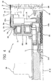
- an apparatus for manufacturing tyres for vehicle wheels provided for carrying out a method in accordance with the present invention has been generally identified with reference numeral 1.
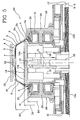
- Apparatus 1 is designed for manufacture of tyres 2 ( Fig. 5 ) essentially comprising at least one carcass ply 3 preferably internally coated with a layer of elastomeric airtight material or a so-called liner 4.
- Two annular anchoring structures 5, each comprising a so-called bead core 5a carrying an elastomeric filler 5b at a radially external position, are engaged with respective end flaps 3a of the carcass ply or plies 3.
- annular anchoring structures 5 Integration of the annular anchoring structures 5 occurs close to regions usually identified as "beads" 6, at which usually engagement between tyre 2 and a respective mounting rim (not shown) takes place, according to a fitting diameter D0 determined by the inner diametrical sizes of the annular anchoring structures 5.
- a belt structure 7 is circumferentially applied around the carcass ply/plies 3 and a tread band 8 circumferentially overlaps the belt structure 7.
- Apparatus 1 comprises a building drum 10 having two halves 10a supported by a central shaft 11 extending along a geometric axis X-X of the building drum 10 itself.
- Halves 10a can be moved axially close to each other, upon command of a screw threaded bar for example, that is operatively disposed within the central shaft 11 and carries two threaded portions 12a, 12b, a right-hand one and a left-hand one respectively, each of them engaging one of halves 10a.
- Halves 10a of the building drum 10 are consequently induced to simultaneously translate in respectively opposite directions along the central shaft 11, following rotations imparted to the screw threaded bar 12 by means of an actuator (not shown) that can be operatively coupled to one end of the central shaft 11.
- the building drum 10 can further comprise a central section 13 slidably engaging halves 10a and extending in surface-continuity relationship with the latter so as to define a substantially continuous outer surface 14 with them.
- halves 10a of the building drum 10 can axially extend towards each other having mutually-meshing respective toothings, i.e. in which the teeth of each toothing are slidably inserted in an alternated sequence between the teeth belonging to the other half.
- the halves 10a and central section 13 are each made up of respective circumferential sectors, radially movable between a rest condition (not shown) at which they are disposed radially close to the geometric axis X-X to give the building drum 10 a diametrical bulkiness smaller than the fitting diameter D0 of the tyre under processing, so as to enable removal of the built tyre 2 from the building drum itself, and a work condition at which, as shown in the accompanying figures, said sectors extend in circumferential-continuity relationship so as to form said outer surface 14 defining an application diameter D1 that is significantly greater than the fitting diameter D0.
- radial movement of the circumferential sectors is carried out through a plurality of connecting rods 15, each of them being linked between one of the sectors of the central section 13 of the building drum 10, and a drive collar 16 rotatably carried by the central shaft 11 and drivable in angular rotation by means of an outer actuator (not shown).
- transmission bars 17 axially extending through the sectors of the central section 13, the radial movements of the latter are transmitted to the circumferential sectors of the axially opposite halves 10a of the building drum 10, slidably guided along respective columns 18 radially extending relative to the central shaft 11.
- the building drum 10 lends itself to be transferred by at least one robotized arm (not shown) or transfer devices of other type operating on at least one grip end 11a provided by the central shaft 11, to one or more work stations 19, 20 to enable carrying out of different working steps aiming at assembling the tyre 2 being processed.
- the building drum 10 is first engaged in a building station 19 ( Figs. 1 to 3 ) in which a so-called carcass sleeve 21 comprising the carcass ply/plies 3 coupled to the respective annular anchoring structures 5 is made.
- the building station 19 is preferably equipped with auxiliary support members 22, made in the form of two annular elements for example, that are adapted to removably approach the building drum 10 on axially opposite sides.
- the auxiliary support members 22 have respective rest surfaces 22a preferably having a substantially cylindrical conformation, the diameter of which is substantially the same as the application diameter D1. When approaching has occurred, the rest surfaces 22a extend without interruption in the continuation of the outer surface 14.
- auxiliary devices can operate for application of first components of the carcass sleeve 21 at the building drum 10.
- these auxiliary devices can comprise one or more dispensing members for example, which supply at least one continuous elongated element of elastomeric material while the building drum 10 is being driven in rotation around its geometric axis X-X, so as to form the above mentioned liner 4 on the outer surface 14 and the rest surfaces 22a.
- auxiliary devices can be designed to form abrasion-preventing inserts on the rest surfaces 22a, which inserts are to be incorporated in the region of beads 6 and/or, in case of the so-called run-flat tyres, auxiliary support inserts made of elastomeric material (the so-called sidewall inserts) applied to the respective halves 10a of the building drum 10, so that they are then incorporated into tyre 2 in the sidewall 9 region.
- each carcass ply 3 can consist of a manufactured article in the form of a continuous strip previously cut according to the circumferential extension of the outer surface 14 and delivered towards said outer surface, while the building drum 10 is rotating around its geometric axis X-X, so as to cause winding of said strip around the outer surface 14.
- the application devices comprise members for sequentially applying a plurality of strip-like elements disposed transversely of the circumferential extension of the outer surface 14, while the building drum 10 is being driven in rotation following a step-by-step operation, in the same manner as described in US 6,328,084 in the name of the same Applicant, for example.
- strip-like element it is intended an elementary component having an elongated conformation and comprising one or more reinforcing cords associated with an elastomeric matrix, the length of which subtends the width of the carcass ply/plies 3 and which has a width corresponding to a fraction of the circumferential extension of the carcass ply/plies 3 themselves.
- carcass ply/plies 3 are directly formed on the building drum 10, by means of the strip-like elements applied in mutually approached relationship to cover the whole circumferential extension of the outer surface 14.
- the outer surface 14 has a smaller axial dimension than the width of said at least one carcass ply 3, so that the end flaps 3a of the carcass ply/plies 3 disposed on the building drum 10 axially project from the opposite ends of the outer surface 14 and are at least partly supported by said rest surfaces 22a.
- the auxiliary support members 22 are axially moved apart from the respective halves 10a of the building drum 10, so as to remove the rest surfaces 22a from liner 4 and from the carcass ply/plies 3, by slipping off. Removal of the rest surfaces 22a makes it possible to fold down the end flaps 3a of the carcass ply/plies 3 applied around the building drum 10, towards the geometric axis X-X of the building drum 10 itself, with the aid of rollers or other devices not shown for example, that can be made in any convenient manner.
- inflatable bags 23 or other turning-up members carry out turning up of each of the end flaps 3a around the respective annular anchoring structure, so as to stabilise engagement of the latter with the carcass ply 3 causing formation of said carcass sleeve 21.
- the building drum 10 carrying the carcass sleeve 21 is then transferred from the building station 19 to a shaping station 20 ( Figs. 4 and 5 ) to receive an outer sleeve 24 in engagement, which integrates the belt structure 7 preferably already coupled to the tread band 8.
- the outer sleeve 24 can be previously prepared by formation or winding of one or more belt layers adapted to form the belt structure 7, on an auxiliary drum (not shown), and subsequent winding of the tread band 8 on the belt structure 7 carried by the auxiliary drum. More specifically, building of the tread band 8 can be carried out by dispensing members delivering an elastomeric continuous elongated element that is applied in the form of coils disposed in side by side relationship and radially superposed on the belt structure 7 carried by the auxiliary drum, while the latter is being driven in rotation.
- the outer sleeve 24 thus formed is adapted to be removed from the auxiliary drum, by a transfer ring 25 for example or other suitable devices that will then transfer it to the shaping station 20 where it is disposed in a coaxially centred position around the carcass sleeve 21 carried by the building drum 10.
- Shaping devices acting on the building drum 10 operate in the shaping station 20 to shape the carcass sleeve 21 into a toroidal configuration ( Fig. 5 ), so as to cause application of same against a radially internal surface of the outer sleeve 24.
- the shaping devices can for example comprise said actuator (not shown) designed to drive the screw threaded bar 12 in rotation to cause mutual axial approaching of halves 10a of the drum and, as a result, of the annular anchoring structures 5 of the carcass sleeve 21.
- the shaping devices further comprise inflating members having a pneumatic circuit connected at least with a feeding duct 26 formed along the central shaft 11 for example, to feed the carcass sleeve 21 with a working fluid and cause radial expansion of same through inflation, during mutual approaching of the annular anchoring structures 5.
- At least one one-way valve 27 is associated with the feeding duct 26 to prevent the fluid from flowing back from the carcass sleeve 21 to the feeding duct 26, so as to keep the carcass sleeve 21 in an inflated condition even when the feeding duct 26 is disconnected from the pneumatic circuit.
- locking members 28 can also operate in the shaping station 20 to lock the annular anchoring structures 5 relative to the building drum 10.
- the locking members 28 can for example comprise a pair of flanges 29 to be removably fastened to the shaping drum 10 in axially approached relationship and on respectively opposite sides.
- Each flange 29 carries one annular element 30 that can be elastically deformed between a rest condition and a radially expanded condition.
- each annular element 30 is of made of one piece alone to minimise the geometric distortion effects due to passage between the rest condition and the radially expanded condition.
- a thrust ring 31 is drivable to cause elastic deformation of the annular element itself between the rest condition and the radially expanded condition, said ring being operated by a working fluid for example.
- flanges 29 are axially positioned relative to the annular anchoring structures 5, with the respective annular elements 30 in a rest condition that are at least partly radially fitted inside the annular anchoring structures themselves.
- the thrust rings 31 are then fluid operated to bring the annular elements 30 to a radially expanded condition.
- the annular elements 30 operate in radial-thrust relationship from the inside to the outside against the radially internal surfaces of the annular anchoring structures 5 causing an efficient locking of same in terms of stresses transmitted during the subsequent shaping step.
- each annular element 30 has a continuous circumferential extension, so that it performs the function of a hermetically-sealed closure element of the carcass sleeve 21 at the annular anchoring structures 5, facilitating radial expansion of the sleeve itself and maintenance of the inflated condition, following the shaping step.
- the Applicant has found preferable for the application diameter D1 of the carcass ply/plies 3 to be included between about 102% and about 120% of the fitting diameter D0.
- said application diameter D1 can be included between about 105% and about 115% of the fitting diameter D0.
- the application diameter D1 is included between about 30% and about 90% of the inner diameter D2 of the outer sleeve 24 (which is coincident with the inner diameter of the belt structure).
- said application diameter D1 is included between about 50% and about 80% of the inner diameter D2 of the outer sleeve 24.
- the difference between the application diameter D1 and the fitting diameter D0 is also preferable for the difference between the application diameter D1 and the fitting diameter D0 to be included between about 2% and about 70% of the difference between the inner diameter D2 of the outer sleeve 24 and the fitting diameter D0.
- the difference between the application diameter D1 and the fitting diameter D0 can be included between about 20% and about 50% of the difference between the inner diameter D2 of the outer sleeve 24 and the fitting diameter D0.
- the process and apparatus in accordance with the invention is to be preferably used for manufacturing high and ultra high performance low-section tyres.
- the building drum 10 can be removed from the shaping station 20 to be possibly transferred to at least one additional work station (not shown), designed for manufacture of the sidewalls 9 for example.
- the presence of the one-way valve 27 and of flanges 29 with the annular elements 30 in a radially expanded condition against the annular anchoring structures 5 maintains the carcass sleeve 21 to an inflated condition, so as to facilitate application of the sidewalls 9 and/or other working operations to be carried out in the additional work stations 19, 20.
- tyre 2 can be removed from the building drum 10, upon radial contraction of the latter, for being submitted to a vulcanisation step to be carried out in any convenient manner.
Landscapes
- Engineering & Computer Science (AREA)
- Mechanical Engineering (AREA)
- Manufacturing & Machinery (AREA)
- Tyre Moulding (AREA)
- Processing And Handling Of Plastics And Other Materials For Molding In General (AREA)
- Heating, Cooling, Or Curing Plastics Or The Like In General (AREA)
- Micro-Organisms Or Cultivation Processes Thereof (AREA)
Claims (25)
- Procédé pour la fabrication de pneus, comportant les étapes suivantes :- appliquer au moins une nappe de carcasse (3) autour d'au moins une surface extérieure (14) d'un tambour de construction (10) ayant un diamètre d'application (D1), l'au moins une nappe de carcasse (3) ayant des rabats d'extrémité (3a) opposés axialement ;- engager coaxialement autour de chacun des rabats d'extrémité (3a), une structure d'ancrage annulaire (5) définissant un diamètre d'ajustement (D0) plus petit que le diamètre d'application (D1) afin de constituer un manchon de carcasse (21) ;- positionner un manchon extérieur (24) comportant au moins une structure de ceinture (7) à une position coaxialement centrée autour du manchon de carcasse (21) appliqué sur le tambour de construction (10) ;- former le manchon de carcasse (21) dans une configuration toroïdale pour déterminer l'application de celui-ci contre une surface radialement intérieure du manchon extérieur (24),dans lequel l'application de l'au moins une nappe de carcasse (3) comporte une étape d'application de plusieurs éléments en forme de bandes disposés successivement le long de l'étendue circonférentielle de la surface extérieure (14) du tambour de construction (10),
dans lequel le diamètre d'application (D1) est plus grand que ou égal à environ 102% du diamètre d'ajustement (D0), et le diamètre d'application (D1) est plus petit que ou égal à environ 120% du diamètre d'ajustement (D0). - Procédé selon la revendication 1, dans lequel le diamètre d'application (D1) est plus grand que ou égal à environ 30% du diamètre intérieur (D2) du manchon extérieur (24).
- Procédé selon l'une au moins des revendications précédentes, dans lequel le diamètre d'application (D1) est plus petit que ou égal à environ 90% du diamètre intérieur (D2) du manchon extérieur (24).
- Procédé selon l'une au moins des revendications précédentes, dans lequel la différence entre le diamètre d'application (D1) et le diamètre d'ajustement (D0) est plus grand que ou égal à environ 2% de la différence entre le diamètre intérieur (D2) du manchon extérieur (24) et le diamètre d'ajustement (D0).
- Procédé selon l'une au moins des revendications précédentes, dans lequel la différence entre le diamètre d'application (D1) et le diamètre d'ajustement (D0) est plus petit que ou égal à environ 70% de la différence entre le diamètre intérieur (D2) du manchon extérieur (24) et le diamètre d'ajustement (D0).
- Procédé selon l'une au moins des revendications précédentes, dans lequel pendant l'application de l'au moins une nappe de carcasse (3) sur le tambour de construction (10), les rabats d'extrémité (3a) de l'au moins une nappe de carcasse (3) sont supportés sur des surfaces d'appui (22a) respectives s'étendant dans le prolongement de la surface extérieure (14) du tambour de construction (10).
- Procédé selon l'une au moins des revendications précédentes, dans lequel avant l'étape d'application de l'au moins une nappe de carcasse (3) sur le tambour de construction (10), l'application d'au moins un premier composant (4) du manchon de carcasse (21) est réalisée sur le tambour de construction (10).
- Procédé selon la revendication précédente, dans lequel l'au moins un premier composant (4) est au moins partiellement appliqué sur des surfaces d'appui (22a) respectives s'étendant selon des directions axialement opposées dans le prolongement de la surface extérieure (14) du tambour de construction (10).
- Procédé selon l'une au moins des revendications 6 à 8, comportant en outre l'étape de retirer les surfaces d'appui (22a) avant de rabattre les rabats d'extrémité (3a) de l'au moins une nappe d'extrémité (3).
- Procédé selon l'une au moins des revendications précédentes, dans lequel les structures d'ancrage annulaires (5) sont bloquées par rapport au tambour de construction (10) pendant l'étape de formage.
- Procédé selon la revendication précédente, dans lequel simultanément à l'étape de blocage, le manchon de carcasse (21) est mis en relation d'étanchéité avec les structures d'ancrage annulaires (5).
- Procédé selon l'une au moins des revendications précédentes, comportant en outre une étape de transfert du tambour de construction (10).
- Procédé selon l'une au moins des revendications précédentes, dans lequel le tambour de construction est transféré depuis un poste de construction (19) vers un poste de formage (20) avant l'étape de positionnement du manchon extérieur (24).
- Procédé selon l'une quelconque des revendications précédentes, dans lequel le pneu construit (2) a une hauteur de section, mesurée entre un point radialement le plus à l'extérieur de la bande de roulement (8) et un point radialement le plus à l'intérieur du talon (6), compris entre environ 20% et environ 50% d'une largeur de section mesurée axialement à un point de corde maximale du pneu (2).
- Appareil pour la contruction de pneus, comportant :- un tambour de construction (10) ayant au moins une surface extérieure (14) définissant un diamètre d'application (D1) ;- des dispositifs pour appliquer au moins une nappe de carcasse (3) autour de la surface extérieure (14), selon le diamètre d'application (D1), l'au moins une nappe de carcasse (3) ayant des rabats d'extrémité (3a) axialement opposés ;- des dispositifs pour engager coaxialement, autour de chacun des rabats d'extrémité (3a), une structure d'ancrage annulaire (5) définissant un diamètre d'ajustement (D0) plus petit que le diamètre d'application (D1) afin de constituer un manchon de carcasse (21) ;- des dispositifs pour positionner un manchon extérieur (24) comportant au moins une structure de ceinture (7) en une position coaxialement centrée autour du manchon de carcasse (21) appliqué sur le tambour de construction (10) ;- des dispositifs de formage fonctionnant sur le tambour de construction (10) pour former le manchon de carcasse (21) dans une configuration toroïdale,caractérisé en ce que les dispositifs pour l'application de l'au moins une nappe de carcasse (3) comportent des organes pour l'application de plusieurs éléments en forme de bandes consécutivement en succession et circonférentiellement proches les uns des autres le long de l'étendue circonférentielle de la surface extérieure (14) du tambour de construction (10), le diamètre d'application (D1) étant plus grand que ou égal à environ 102% du diamètre d'ajustement (D0), et le diamètre d'application (D1) étant plus petit que ou égal à environ 120% du diamètre d'ajustement (D0).
- Appareil selon la revendication 15, comportant en outre des organes support auxiliaires (22) susceptibles d'être déplacés de manière amovible à proximité du tambour de construction (10) sur des côtés axialement opposés, et ayant des surfaces d'appui (22a) respectives s'étendant dans le prolongement de la surface extérieure (14).
- Appareil selon la revendication précédente, dans lequel les surfaces d'appui (22a) ont une forme sensiblement cylindrique, ayant le même diamètre que le diamètre d'application (D1).
- Appareil selon la revendication 15, comportant en outre des dispositifs auxiliaires pour l'application d'au moins un premier composant (4) du manchon de carcasse (21) sur le tambour de construction (10).
- Appareil selon la revendication précédente, dans lequel le dispositif auxiliaire applique l'au moins un premier composant (4) au moins partiellement sur les surfaces d'appui (22a) s'étendant dans le prolongement de la surface extérieure (14).
- Appareil selon la revendication 15, comportant en outre des organes de blocage (28) pour les structures d'ancrage annulaires (5) par rapport au tambour de construction (10).
- Appareil selon la revendication 20, dans lequel les organes de blocage (28) peuvent être attachés de manière amovible au tambour de construction (10).
- Appareil selon la revendication 20, comportant en outre des éléments de fermeture fonctionnellement associés avec les organes de blocage (28) pour réaliser un sceau hermétique du manchon de carcasse (21) à la structure d'ancrage annulaire (5).
- Appareil selon la revendication 22, dans lequel les éléments de fermeture comportent au moins un élément annulaire (30) qui est déformable radialement entre un état de repos et un état agrandi radialement.
- Appareil selon la revendication 23, dans lequel l'élément annulaire (30) est formé d'une seule pièce.
- Appareil selon la revendication 15, comportant en outre :- un poste de construction (19) transportant les dispositifs d'application pour l'au moins une nappe de carcasse (3) ;- un poste de formage (20) transportant les dispositifs de formage ;- des dispositifs de transfert pour déplacer le tambour de construction (10) depuis le poste de construction (19) vers le poste de formage (20).
Priority Applications (1)
| Application Number | Priority Date | Filing Date | Title |
|---|---|---|---|
| PL07705890T PL2117820T3 (pl) | 2007-02-15 | 2007-02-15 | Sposób i aparat do wytwarzania opon |
Applications Claiming Priority (1)
| Application Number | Priority Date | Filing Date | Title |
|---|---|---|---|
| PCT/IB2007/050498 WO2008099236A1 (fr) | 2007-02-15 | 2007-02-15 | Procédé et appareil de fabrication de pneus |
Publications (2)
| Publication Number | Publication Date |
|---|---|
| EP2117820A1 EP2117820A1 (fr) | 2009-11-18 |
| EP2117820B1 true EP2117820B1 (fr) | 2011-12-07 |
Family
ID=38608717
Family Applications (2)
| Application Number | Title | Priority Date | Filing Date |
|---|---|---|---|
| EP07705890A Active EP2117820B1 (fr) | 2007-02-15 | 2007-02-15 | Procédé et appareil de fabrication de pneus |
| EP08710036A Active EP2111334B1 (fr) | 2007-02-15 | 2008-02-14 | Procede et appareil pour fabriquer des pneus |
Family Applications After (1)
| Application Number | Title | Priority Date | Filing Date |
|---|---|---|---|
| EP08710036A Active EP2111334B1 (fr) | 2007-02-15 | 2008-02-14 | Procede et appareil pour fabriquer des pneus |
Country Status (12)
| Country | Link |
|---|---|
| US (4) | US9630369B2 (fr) |
| EP (2) | EP2117820B1 (fr) |
| JP (2) | JP5364593B2 (fr) |
| KR (2) | KR101364664B1 (fr) |
| CN (2) | CN101600562B (fr) |
| AT (2) | ATE536249T1 (fr) |
| BR (2) | BRPI0721133B1 (fr) |
| DE (1) | DE602008006023D1 (fr) |
| ES (1) | ES2363997T3 (fr) |
| PL (2) | PL2117820T3 (fr) |
| RU (1) | RU2455165C2 (fr) |
| WO (2) | WO2008099236A1 (fr) |
Families Citing this family (34)
| Publication number | Priority date | Publication date | Assignee | Title |
|---|---|---|---|---|
| PL2117820T3 (pl) * | 2007-02-15 | 2012-05-31 | Pirelli | Sposób i aparat do wytwarzania opon |
| CN102046360B (zh) | 2008-04-18 | 2013-10-16 | 倍耐力轮胎股份公司 | 用于组装轮胎的方法和设备 |
| WO2009144753A1 (fr) * | 2008-05-28 | 2009-12-03 | Pirelli Tyre S.P.A. | Procédé et appareil de confection de pneus |
| CN102196899B (zh) | 2008-10-31 | 2014-04-16 | 倍耐力轮胎股份公司 | 用于构建轮胎的方法 |
| BR122018075477B1 (pt) | 2008-12-02 | 2019-03-26 | Pirelli Tyre S.P.A. | Aparelho para fabricar pneus para rodas de veículos |
| CN102227305B (zh) | 2008-12-15 | 2014-08-06 | 倍耐力轮胎股份公司 | 用于制造轮胎的方法以及通过所述方法获得的轮胎 |
| EP2440398B1 (fr) | 2009-06-09 | 2014-07-09 | Pirelli Tyre S.p.A. | Procédé de contrôle de l'évacuation de fluides au cours d'un processus de moulage et de vulcanisation d'un pneu cru et pneu pour roues de véhicule ainsi obtenu. |
| RU2535714C2 (ru) | 2009-08-12 | 2014-12-20 | Пирелли Тайр С.П.А. | Способ и установка для сборки шин для колес транспортных средств |
| FR2954212A1 (fr) * | 2009-12-18 | 2011-06-24 | Michelin Soc Tech | Dispositif et procede d'assemblage d'une ebauche de pneumatique |
| JP6208944B2 (ja) | 2009-12-22 | 2017-10-04 | ピレリ・タイヤ・ソチエタ・ペル・アツィオーニ | 車両車輪用グリーンタイヤを組み立てるための工程およびプラント |
| KR101145188B1 (ko) * | 2010-05-13 | 2012-05-14 | 이강배 | 자동차용 타이어의 제조 방법, 자동차 타이어 제조용 트레드 하우징 및 생타이어 제조 장치 |
| US8585845B2 (en) | 2010-11-10 | 2013-11-19 | The Goodyear Tire & Rubber Company | Tire-forming apparatus and related methods |
| DE102010061245A1 (de) * | 2010-12-15 | 2012-06-21 | Continental Reifen Deutschland Gmbh | Verfahren zur Herstellung eines Fahrzeugreifens |
| ITMI20112370A1 (it) | 2011-12-23 | 2013-06-24 | Pirelli | Processo e impianto di confezionamento di pneumatici per ruote di veicoli |
| JP5592420B2 (ja) * | 2012-02-15 | 2014-09-17 | 住友ゴム工業株式会社 | トラックまたはバス用タイヤ |
| ITMI20121757A1 (it) | 2012-10-17 | 2014-04-18 | Pirelli | Metodo e impianto per confezionare pneumatici per ruote di veicoli |
| CN104884239B (zh) * | 2012-11-27 | 2018-03-06 | 倍耐力轮胎股份公司 | 用于构造车轮用轮胎的方法和设备 |
| ITMI20122148A1 (it) | 2012-12-17 | 2014-06-18 | Pirelli | Processo ed apparato per realizzare pneumatici |
| ITMI20122179A1 (it) | 2012-12-19 | 2014-06-20 | Pirelli | Metodo per verificare la corretta formazione dei talloni in un processo e in un impianto per confezionare pneumatici per ruote di veicoli. |
| JP6360880B2 (ja) * | 2013-02-22 | 2018-07-18 | ハールブルク・フロイデンベルガー マシーネンバウ ゲーエムベーハー | グリーンタイヤを製造するための方法および装置 |
| WO2014135995A2 (fr) | 2013-03-06 | 2014-09-12 | Pirelli Tyre S.P.A. | Procédé pour construire des pneus pour roues de véhicule, pneu pour roues de véhicule et procédé pour optimiser la répartition de charges dans la structure de carcasse d'un pneu |
| WO2014167456A1 (fr) | 2013-04-10 | 2014-10-16 | Pirelli Tyre S.P.A. | Procédé et moule de vulcanisation pour la fabrication de pneus pour roues de véhicules |
| WO2014203211A1 (fr) * | 2013-06-21 | 2014-12-24 | Pirelli Tyre S.P.A. | Procédé et appareil de production de pneus pour des roues de véhicule |
| BR112015032608B1 (pt) * | 2013-08-01 | 2021-01-12 | Pirelli Tyre S.P.A. | processo e aparelho para fabricar pneus para rodas de veículos, e, pneu para rodas de veículo |
| MX2016006407A (es) | 2013-11-26 | 2016-10-28 | Pirelli | Metodo, proceso y planta para construir llantas. |
| WO2015181783A1 (fr) * | 2014-05-30 | 2015-12-03 | Pirelli Tyre S.P.A. | Procédé et appareil de production de pneus pour roues de véhicule |
| US10442148B2 (en) * | 2014-10-03 | 2019-10-15 | Fuji Seiko Co., Ltd. | Filler-raising device |
| WO2016060560A1 (fr) * | 2014-10-13 | 2016-04-21 | Vmi Holland B.V. | Procédé et tambour pour la fabrication d'un pneu, en particulier d'un pneu de roulage à plat |
| JP6495033B2 (ja) * | 2015-02-09 | 2019-04-03 | 株式会社神戸製鋼所 | タイヤ試験用リム |
| WO2017115173A1 (fr) | 2015-12-28 | 2017-07-06 | Pirelli Tyre S.P.A. | Procédé et installation pour la fabrication de pneumatiques |
| BR112019010473B1 (pt) * | 2016-12-20 | 2022-11-16 | Pirelli Tyre S.P.A. | Método para verificação da formação de talões de pneus, processos para formação de talões de pneus e para produção de pneus, e, estação para formação de talões de pneus |
| IT201700084375A1 (it) * | 2017-07-25 | 2019-01-25 | Pirelli | Apparato per il confezionamento di uno pneumatico per ruote di veicoli |
| IT201900023616A1 (it) | 2019-12-11 | 2021-06-11 | Pirelli | Tamburo di formatura per la produzione di pneumatici per ruote di veicoli e metodo per controllare la geometria di un tamburo di formatura per la produzione di pneumatici per ruote di veicoli |
| CN116922837B (zh) * | 2023-08-01 | 2024-04-19 | 肇庆骏鸿实业有限公司 | 两次法成型机一段全自动胎侧胶贴合装置 |
Family Cites Families (75)
| Publication number | Priority date | Publication date | Assignee | Title |
|---|---|---|---|---|
| US1756327A (en) * | 1928-09-12 | 1930-04-29 | Miller Rubber Co | Bead-setting ring |
| US1871604A (en) * | 1930-11-15 | 1932-08-16 | Gen Tire & Rubber Co | Bead placing ring |
| US2045545A (en) * | 1933-10-30 | 1936-06-23 | Nat Standard Co | Process and apparatus for making drum built tires |
| US2208324A (en) * | 1935-08-05 | 1940-07-16 | Wingfoot Corp | Apparatus for building tires |
| US2319643A (en) * | 1937-08-19 | 1943-05-18 | Goodrich Co B F | Pneumatic tire machine |
| US2824336A (en) * | 1953-03-19 | 1958-02-25 | Us Rubber Co | Apparatus for treating pneumatic tires |
| US2754886A (en) * | 1953-09-29 | 1956-07-17 | Firestone Tire & Rubber Co | Tire building apparatus |
| US2818907A (en) * | 1955-05-26 | 1958-01-07 | Goodrich Co B F | Tire building machinery |
| US2814331A (en) * | 1956-04-20 | 1957-11-26 | Vanzo Marcello | Process for building pneumatic tires |
| US3816202A (en) * | 1969-02-19 | 1974-06-11 | Goodyear Tire & Rubber | Tire building method and machine |
| FR2051920A5 (fr) * | 1969-07-01 | 1971-04-09 | Englebert | |
| FR2082693A5 (fr) * | 1970-03-24 | 1971-12-10 | Dunlop Ltd | |
| US3728194A (en) * | 1970-11-27 | 1973-04-17 | Nrm Corp | Rotating expandable ply ring mechanism |
| DE2108781B2 (de) * | 1971-02-24 | 1981-05-07 | Dunlop Ag, 6450 Hanau | Verfahren und Vorrichtung zum Aufbau eines Radialgürtelreifens |
| US3740293A (en) * | 1971-05-17 | 1973-06-19 | Nrm Corp | Tire building machine |
| BE786079A (fr) * | 1971-07-13 | 1973-01-10 | Uniroyal Sa | Appareil et procede pour fabriquer des bandages |
| US3990931A (en) * | 1972-07-06 | 1976-11-09 | Uniroyal, S.A. | Tire building apparatus and method |
| US3826297A (en) * | 1972-10-26 | 1974-07-30 | Steelastic Co | Radial tire carcass |
| AT341358B (de) * | 1974-03-01 | 1978-02-10 | Phoenix Gummiwerke Ag | Vorrichtung zum bombieren von karkassenrohlingen fur gurtelreifen |
| US4131500A (en) * | 1974-12-09 | 1978-12-26 | Avon Tyres Limited | Tire building drum |
| SU521142A1 (ru) | 1975-02-28 | 1976-07-15 | Научно-Исследовательский Конструкторско-Технологический Институт Шинной Промышленности | Способ сборки каркасов покрышек пневматических шин |
| US4081310A (en) * | 1975-06-25 | 1978-03-28 | Uniroyal, Inc. | Bead grip ring |
| SU687720A1 (ru) | 1976-12-29 | 1991-03-07 | Научно-Исследовательский, Конструкторско-Технологический Институт Шинной Промышленности | Устройство дл сборки покрышки пневматической шины |
| IT1144468B (it) | 1981-08-12 | 1986-10-29 | Firestone Int Dev Spa | Dispositivo di prima formatura di carcasse di pneumatici |
| JPS60141540A (ja) * | 1983-12-28 | 1985-07-26 | Yokohama Rubber Co Ltd:The | タイヤ成型機のセカンドタイヤフオ−マ−装置 |
| GB8403351D0 (en) | 1984-02-08 | 1984-03-14 | Wyko Equipment Ltd | Tyre building drum |
| SU1281442A1 (ru) | 1985-03-22 | 1987-01-07 | Ярославский политехнический институт | Барабан дл сборки покрышек пневматических шин |
| DD284640B5 (de) * | 1989-06-08 | 1993-09-16 | Fuerstenwalde Pneumant Reifen | Konfektioniertrommel zur herstellung von fahrzeugluftreifen |
| US5268057A (en) * | 1989-12-14 | 1993-12-07 | Sumitomo Rubber Industries Ltd. | Tire building apparatus |
| JPH0675931B2 (ja) * | 1989-12-14 | 1994-09-28 | 住友ゴム工業株式会社 | タイヤ成形フォーマー |
| JPH0675932B2 (ja) * | 1989-12-18 | 1994-09-28 | 住友ゴム工業株式会社 | タイヤ成形装置 |
| JP3080966B2 (ja) * | 1990-05-02 | 2000-08-28 | 株式会社ブリヂストン | タイヤ成型装置 |
| NL9001645A (nl) * | 1990-07-19 | 1992-02-17 | Vmi Epe Holland | Mechanisme voor het steunen en vastleggen van de hielen bij het bouwen van luchtbanden. |
| JPH089204B2 (ja) | 1990-07-25 | 1996-01-31 | 住友ゴム工業株式会社 | 生タイヤの成形方法及びベルト成形ドラム |
| JP3043799B2 (ja) * | 1990-11-14 | 2000-05-22 | 株式会社ブリヂストン | タイヤ成型ドラム |
| IT1254431B (it) * | 1992-02-11 | 1995-09-25 | Pirelli | Impianto per il confezionamento di carcasse di pneumatici per ruote di veicoli |
| JP3091578B2 (ja) | 1992-08-06 | 2000-09-25 | 住友ゴム工業株式会社 | タイヤの製造方法、それに用いるタイヤ成形装置、その製造方法により製造されたタイヤ |
| JP3131854B2 (ja) | 1992-08-25 | 2001-02-05 | キヤノン株式会社 | ワンチップマイコン |
| JPH0724930A (ja) * | 1993-07-09 | 1995-01-27 | Bridgestone Corp | タイヤ成形ドラム |
| JP2644168B2 (ja) * | 1993-07-14 | 1997-08-25 | 住友ゴム工業株式会社 | タイヤ成形機用フォーマ |
| FR2720326A1 (fr) * | 1994-05-27 | 1995-12-01 | Sedepro | Assemblage et vulcanisation de pneumatique. |
| JPH09117971A (ja) * | 1995-10-25 | 1997-05-06 | Bridgestone Corp | グリーンケースの製造方法 |
| JPH09131807A (ja) * | 1995-11-13 | 1997-05-20 | Bridgestone Koki Kk | タイヤ成型用ドラム |
| JP3827374B2 (ja) * | 1996-09-13 | 2006-09-27 | 株式会社ブリヂストン | ビードリング成形装置 |
| EP0943421B1 (fr) | 1997-11-28 | 2003-05-28 | Pirelli Pneumatici Societa' Per Azioni | Procédé pour la fabrication de bandages pneumatiques pour roues de véhicule |
| US6328084B1 (en) * | 1997-12-30 | 2001-12-11 | Pirelli Pneumatici S.P.A. | Vehicle tire with a particular carcass ply and/or a particular circumferentially inextensible annular structure |
| US20030041975A1 (en) * | 1998-07-23 | 2003-03-06 | Michelin Recherche Et Technique, S.A. | Apparatus and method for manufacture of tires |
| JP4242957B2 (ja) * | 1998-10-30 | 2009-03-25 | 株式会社ブリヂストン | 空気入りタイヤの製造方法 |
| JP2001038821A (ja) * | 1999-07-23 | 2001-02-13 | Soc De Technol Michelin | タイヤの製造装置およびタイヤの製造方法 |
| US6390166B1 (en) * | 2000-05-19 | 2002-05-21 | Wyko, Inc. | Expandable mandrel having adjustable width |
| JP4167817B2 (ja) | 2000-08-21 | 2008-10-22 | 不二精工株式会社 | タイヤの生産システム及び生産方法 |
| JP4593748B2 (ja) * | 2000-09-01 | 2010-12-08 | 住友ゴム工業株式会社 | タイヤ製造方法 |
| US6656301B2 (en) * | 2001-01-11 | 2003-12-02 | Bridgestone/Firestone North American Tire, Llc | Green tire storage device with inflatable bladders |
| ES2336494T3 (es) * | 2001-01-12 | 2010-04-13 | Bridgestone Corporation | Metodo de fabricacion de miembros estructurales para cubiertas y sistema para llevarlo a cabo. |
| JP4447820B2 (ja) * | 2001-02-27 | 2010-04-07 | 東洋ゴム工業株式会社 | タイヤのシェーピング成形ドラム及び成型方法 |
| JP4726165B2 (ja) * | 2001-02-28 | 2011-07-20 | 東洋ゴム工業株式会社 | タイヤ2次成型方法 |
| ITVR20010060A1 (it) | 2001-05-18 | 2002-11-18 | Marangoni Meccanica | Procedimento di fabbricazione di pneumatici crudi. |
| US6863106B2 (en) * | 2001-09-21 | 2005-03-08 | The Goodyear Tire & Rubber Company | Expandable tire building drum with alternating fixed and expandable segments, and contours for sidewall inserts |
| JP3910822B2 (ja) * | 2001-10-24 | 2007-04-25 | 住友ゴム工業株式会社 | 生タイヤ成形用フォーマ |
| CN101298192B (zh) * | 2002-06-05 | 2012-07-04 | 株式会社普利司通 | 轮胎制造方法及轮胎成型鼓 |
| AU2003241659A1 (en) * | 2002-06-18 | 2003-12-31 | Bridgestone Corporation | Device and method for adhering tire component member |
| US20060108051A1 (en) * | 2002-11-05 | 2006-05-25 | Claudio Lacagnina | Process and plant for manufacturing tires for vehicle wheels |
| WO2004060642A2 (fr) | 2002-12-30 | 2004-07-22 | Societe De Technologie Michelin | Dispositif de production de pneu et procede d'assemblage |
| EP1651425B1 (fr) * | 2003-07-30 | 2007-01-24 | Pirelli Tyre S.p.A. | Procede et appareil pour la production de pneumatiques pour roues de vehicules |
| US20050028920A1 (en) * | 2003-08-04 | 2005-02-10 | Roedseth John Kolbjoern | High crown first stage tire building drum |
| JP4464700B2 (ja) * | 2004-01-28 | 2010-05-19 | 住友ゴム工業株式会社 | 空気入りタイヤ及びその製造方法 |
| DE102004016659A1 (de) * | 2004-04-05 | 2005-10-27 | Continental Aktiengesellschaft | Verfahren zur Herstellung eines Luftreifens |
| GB0413275D0 (en) | 2004-06-15 | 2004-07-14 | Wyko Equip | Bead lock arrangement |
| DE102004032508A1 (de) * | 2004-07-06 | 2006-02-16 | Continental Aktiengesellschaft | Verfahren und Vorrichtung zum Aufbau eines Radialreifens |
| JP2006021495A (ja) * | 2004-07-09 | 2006-01-26 | Yokohama Rubber Co Ltd:The | 未加硫タイヤ成形機 |
| DE102004036516A1 (de) * | 2004-07-28 | 2006-03-23 | Continental Aktiengesellschaft | Verfahren und Vorrichtung zum Aufbau einer Reifenkarkasse eines Reifenrohlings |
| JP2006043908A (ja) * | 2004-07-30 | 2006-02-16 | Sumitomo Rubber Ind Ltd | タイヤ製造方法 |
| DE102004058522A1 (de) * | 2004-12-04 | 2006-06-14 | Continental Aktiengesellschaft | Verfahren und Vorrichtung zum Aufbauen eines Radialreifens |
| JP2006248163A (ja) * | 2005-03-14 | 2006-09-21 | Yokohama Rubber Co Ltd:The | タイヤ成形機におけるビードクランプ方法及びその装置 |
| PL2117820T3 (pl) * | 2007-02-15 | 2012-05-31 | Pirelli | Sposób i aparat do wytwarzania opon |
-
2007
- 2007-02-15 PL PL07705890T patent/PL2117820T3/pl unknown
- 2007-02-15 EP EP07705890A patent/EP2117820B1/fr active Active
- 2007-02-15 WO PCT/IB2007/050498 patent/WO2008099236A1/fr active Application Filing
- 2007-02-15 JP JP2009549851A patent/JP5364593B2/ja active Active
- 2007-02-15 BR BRPI0721133-3A patent/BRPI0721133B1/pt active IP Right Grant
- 2007-02-15 KR KR1020097015967A patent/KR101364664B1/ko active IP Right Grant
- 2007-02-15 CN CN200780051001.7A patent/CN101600562B/zh active Active
- 2007-02-15 US US12/449,398 patent/US9630369B2/en active Active
- 2007-02-15 AT AT07705890T patent/ATE536249T1/de active
-
2008
- 2008-02-14 PL PL08710036T patent/PL2111334T3/pl unknown
- 2008-02-14 DE DE602008006023T patent/DE602008006023D1/de active Active
- 2008-02-14 WO PCT/IB2008/050538 patent/WO2008099363A1/fr active Application Filing
- 2008-02-14 KR KR1020097016841A patent/KR101376201B1/ko active IP Right Grant
- 2008-02-14 JP JP2009549881A patent/JP5396282B2/ja active Active
- 2008-02-14 BR BRPI0807013-0A2A patent/BRPI0807013A2/pt active IP Right Grant
- 2008-02-14 RU RU2009129126/05A patent/RU2455165C2/ru active
- 2008-02-14 EP EP08710036A patent/EP2111334B1/fr active Active
- 2008-02-14 AT AT08710036T patent/ATE504422T1/de not_active IP Right Cessation
- 2008-02-14 ES ES08710036T patent/ES2363997T3/es active Active
- 2008-02-14 US US12/449,518 patent/US9457530B2/en active Active
- 2008-02-14 CN CN2008800051294A patent/CN101610897B/zh active Active
-
2016
- 2016-08-09 US US15/231,864 patent/US10414111B2/en active Active
-
2017
- 2017-03-16 US US15/460,697 patent/US10940654B2/en active Active
Also Published As
Similar Documents
| Publication | Publication Date | Title |
|---|---|---|
| US10940654B2 (en) | Process and apparatus for manufacturing tyres | |
| US11718054B2 (en) | Apparatus for building tyres for vehicle wheels | |
| US9156218B2 (en) | Apparatus for producing pneumatic tyres | |
| US10792876B2 (en) | Process and apparatus for building tyres | |
| WO2008007400A1 (fr) | Procédé et appareil permettant de produire des bandages pneumatiques | |
| EP1556208B1 (fr) | Procede et appareil de fabrication de pneumatiques pour roues de vehicules | |
| EP1556207B1 (fr) | Procede et appareil de fabrication de pneumatique de roues de vehicule | |
| JP2012250545A (ja) | タイヤを組み立てる装置 |
Legal Events
| Date | Code | Title | Description |
|---|---|---|---|
| PUAI | Public reference made under article 153(3) epc to a published international application that has entered the european phase |
Free format text: ORIGINAL CODE: 0009012 |
|
| 17P | Request for examination filed |
Effective date: 20090630 |
|
| AK | Designated contracting states |
Kind code of ref document: A1 Designated state(s): AT BE BG CH CY CZ DE DK EE ES FI FR GB GR HU IE IS IT LI LT LU LV MC NL PL PT RO SE SI SK TR |
|
| 17Q | First examination report despatched |
Effective date: 20100310 |
|
| DAX | Request for extension of the european patent (deleted) | ||
| GRAP | Despatch of communication of intention to grant a patent |
Free format text: ORIGINAL CODE: EPIDOSNIGR1 |
|
| GRAS | Grant fee paid |
Free format text: ORIGINAL CODE: EPIDOSNIGR3 |
|
| GRAA | (expected) grant |
Free format text: ORIGINAL CODE: 0009210 |
|
| AK | Designated contracting states |
Kind code of ref document: B1 Designated state(s): AT BE BG CH CY CZ DE DK EE ES FI FR GB GR HU IE IS IT LI LT LU LV MC NL PL PT RO SE SI SK TR |
|
| REG | Reference to a national code |
Ref country code: GB Ref legal event code: FG4D |
|
| REG | Reference to a national code |
Ref country code: CH Ref legal event code: EP |
|
| REG | Reference to a national code |
Ref country code: IE Ref legal event code: FG4D |
|
| REG | Reference to a national code |
Ref country code: DE Ref legal event code: R096 Ref document number: 602007019197 Country of ref document: DE Effective date: 20120209 |
|
| REG | Reference to a national code |
Ref country code: RO Ref legal event code: EPE |
|
| REG | Reference to a national code |
Ref country code: NL Ref legal event code: T3 |
|
| REG | Reference to a national code |
Ref country code: SE Ref legal event code: TRGR |
|
| PG25 | Lapsed in a contracting state [announced via postgrant information from national office to epo] |
Ref country code: LT Free format text: LAPSE BECAUSE OF FAILURE TO SUBMIT A TRANSLATION OF THE DESCRIPTION OR TO PAY THE FEE WITHIN THE PRESCRIBED TIME-LIMIT Effective date: 20111207 |
|
| LTIE | Lt: invalidation of european patent or patent extension |
Effective date: 20111207 |
|
| PG25 | Lapsed in a contracting state [announced via postgrant information from national office to epo] |
Ref country code: GR Free format text: LAPSE BECAUSE OF FAILURE TO SUBMIT A TRANSLATION OF THE DESCRIPTION OR TO PAY THE FEE WITHIN THE PRESCRIBED TIME-LIMIT Effective date: 20120308 Ref country code: LV Free format text: LAPSE BECAUSE OF FAILURE TO SUBMIT A TRANSLATION OF THE DESCRIPTION OR TO PAY THE FEE WITHIN THE PRESCRIBED TIME-LIMIT Effective date: 20111207 Ref country code: SI Free format text: LAPSE BECAUSE OF FAILURE TO SUBMIT A TRANSLATION OF THE DESCRIPTION OR TO PAY THE FEE WITHIN THE PRESCRIBED TIME-LIMIT Effective date: 20111207 |
|
| REG | Reference to a national code |
Ref country code: PL Ref legal event code: T3 |
|
| PG25 | Lapsed in a contracting state [announced via postgrant information from national office to epo] |
Ref country code: BE Free format text: LAPSE BECAUSE OF FAILURE TO SUBMIT A TRANSLATION OF THE DESCRIPTION OR TO PAY THE FEE WITHIN THE PRESCRIBED TIME-LIMIT Effective date: 20111207 Ref country code: CY Free format text: LAPSE BECAUSE OF FAILURE TO SUBMIT A TRANSLATION OF THE DESCRIPTION OR TO PAY THE FEE WITHIN THE PRESCRIBED TIME-LIMIT Effective date: 20111207 |
|
| PG25 | Lapsed in a contracting state [announced via postgrant information from national office to epo] |
Ref country code: EE Free format text: LAPSE BECAUSE OF FAILURE TO SUBMIT A TRANSLATION OF THE DESCRIPTION OR TO PAY THE FEE WITHIN THE PRESCRIBED TIME-LIMIT Effective date: 20111207 Ref country code: IS Free format text: LAPSE BECAUSE OF FAILURE TO SUBMIT A TRANSLATION OF THE DESCRIPTION OR TO PAY THE FEE WITHIN THE PRESCRIBED TIME-LIMIT Effective date: 20120407 Ref country code: BG Free format text: LAPSE BECAUSE OF FAILURE TO SUBMIT A TRANSLATION OF THE DESCRIPTION OR TO PAY THE FEE WITHIN THE PRESCRIBED TIME-LIMIT Effective date: 20120307 Ref country code: SK Free format text: LAPSE BECAUSE OF FAILURE TO SUBMIT A TRANSLATION OF THE DESCRIPTION OR TO PAY THE FEE WITHIN THE PRESCRIBED TIME-LIMIT Effective date: 20111207 |
|
| PG25 | Lapsed in a contracting state [announced via postgrant information from national office to epo] |
Ref country code: PT Free format text: LAPSE BECAUSE OF FAILURE TO SUBMIT A TRANSLATION OF THE DESCRIPTION OR TO PAY THE FEE WITHIN THE PRESCRIBED TIME-LIMIT Effective date: 20120409 |
|
| REG | Reference to a national code |
Ref country code: AT Ref legal event code: MK05 Ref document number: 536249 Country of ref document: AT Kind code of ref document: T Effective date: 20111207 |
|
| PG25 | Lapsed in a contracting state [announced via postgrant information from national office to epo] |
Ref country code: MC Free format text: LAPSE BECAUSE OF NON-PAYMENT OF DUE FEES Effective date: 20120229 |
|
| REG | Reference to a national code |
Ref country code: CH Ref legal event code: PL |
|
| PLBE | No opposition filed within time limit |
Free format text: ORIGINAL CODE: 0009261 |
|
| STAA | Information on the status of an ep patent application or granted ep patent |
Free format text: STATUS: NO OPPOSITION FILED WITHIN TIME LIMIT |
|
| PG25 | Lapsed in a contracting state [announced via postgrant information from national office to epo] |
Ref country code: DK Free format text: LAPSE BECAUSE OF FAILURE TO SUBMIT A TRANSLATION OF THE DESCRIPTION OR TO PAY THE FEE WITHIN THE PRESCRIBED TIME-LIMIT Effective date: 20111207 Ref country code: LI Free format text: LAPSE BECAUSE OF NON-PAYMENT OF DUE FEES Effective date: 20120229 Ref country code: CH Free format text: LAPSE BECAUSE OF NON-PAYMENT OF DUE FEES Effective date: 20120229 |
|
| 26N | No opposition filed |
Effective date: 20120910 |
|
| REG | Reference to a national code |
Ref country code: IE Ref legal event code: MM4A |
|
| REG | Reference to a national code |
Ref country code: DE Ref legal event code: R097 Ref document number: 602007019197 Country of ref document: DE Effective date: 20120910 |
|
| PG25 | Lapsed in a contracting state [announced via postgrant information from national office to epo] |
Ref country code: IE Free format text: LAPSE BECAUSE OF NON-PAYMENT OF DUE FEES Effective date: 20120215 Ref country code: AT Free format text: LAPSE BECAUSE OF FAILURE TO SUBMIT A TRANSLATION OF THE DESCRIPTION OR TO PAY THE FEE WITHIN THE PRESCRIBED TIME-LIMIT Effective date: 20111207 |
|
| PG25 | Lapsed in a contracting state [announced via postgrant information from national office to epo] |
Ref country code: ES Free format text: LAPSE BECAUSE OF FAILURE TO SUBMIT A TRANSLATION OF THE DESCRIPTION OR TO PAY THE FEE WITHIN THE PRESCRIBED TIME-LIMIT Effective date: 20120318 |
|
| PG25 | Lapsed in a contracting state [announced via postgrant information from national office to epo] |
Ref country code: FI Free format text: LAPSE BECAUSE OF FAILURE TO SUBMIT A TRANSLATION OF THE DESCRIPTION OR TO PAY THE FEE WITHIN THE PRESCRIBED TIME-LIMIT Effective date: 20111207 |
|
| PG25 | Lapsed in a contracting state [announced via postgrant information from national office to epo] |
Ref country code: LU Free format text: LAPSE BECAUSE OF NON-PAYMENT OF DUE FEES Effective date: 20120215 |
|
| PG25 | Lapsed in a contracting state [announced via postgrant information from national office to epo] |
Ref country code: HU Free format text: LAPSE BECAUSE OF FAILURE TO SUBMIT A TRANSLATION OF THE DESCRIPTION OR TO PAY THE FEE WITHIN THE PRESCRIBED TIME-LIMIT Effective date: 20070215 |
|
| REG | Reference to a national code |
Ref country code: FR Ref legal event code: PLFP Year of fee payment: 10 |
|
| REG | Reference to a national code |
Ref country code: FR Ref legal event code: PLFP Year of fee payment: 11 |
|
| REG | Reference to a national code |
Ref country code: FR Ref legal event code: PLFP Year of fee payment: 12 |
|
| PGFP | Annual fee paid to national office [announced via postgrant information from national office to epo] |
Ref country code: FR Payment date: 20230223 Year of fee payment: 17 |
|
| PGFP | Annual fee paid to national office [announced via postgrant information from national office to epo] |
Ref country code: TR Payment date: 20230209 Year of fee payment: 17 Ref country code: SE Payment date: 20230227 Year of fee payment: 17 Ref country code: PL Payment date: 20230123 Year of fee payment: 17 Ref country code: IT Payment date: 20230221 Year of fee payment: 17 |
|
| PGFP | Annual fee paid to national office [announced via postgrant information from national office to epo] |
Ref country code: NL Payment date: 20240226 Year of fee payment: 18 |
|
| PGFP | Annual fee paid to national office [announced via postgrant information from national office to epo] |
Ref country code: RO Payment date: 20240125 Year of fee payment: 18 Ref country code: DE Payment date: 20240228 Year of fee payment: 18 Ref country code: CZ Payment date: 20240123 Year of fee payment: 18 Ref country code: GB Payment date: 20240227 Year of fee payment: 18 |