EP2089215B1 - Dreidimensionales druckmaterialsystem - Google Patents
Dreidimensionales druckmaterialsystem Download PDFInfo
- Publication number
- EP2089215B1 EP2089215B1 EP07862625.6A EP07862625A EP2089215B1 EP 2089215 B1 EP2089215 B1 EP 2089215B1 EP 07862625 A EP07862625 A EP 07862625A EP 2089215 B1 EP2089215 B1 EP 2089215B1
- Authority
- EP
- European Patent Office
- Prior art keywords
- particulate material
- kit
- fluid
- fluid binder
- binder
- Prior art date
- Legal status (The legal status is an assumption and is not a legal conclusion. Google has not performed a legal analysis and makes no representation as to the accuracy of the status listed.)
- Active
Links
- 239000000463 material Substances 0.000 title description 51
- 238000010146 3D printing Methods 0.000 title description 22
- 239000011236 particulate material Substances 0.000 claims description 154
- 239000012530 fluid Substances 0.000 claims description 134
- 239000011230 binding agent Substances 0.000 claims description 133
- 239000000945 filler Substances 0.000 claims description 60
- 239000000178 monomer Substances 0.000 claims description 47
- NIXOWILDQLNWCW-UHFFFAOYSA-M Acrylate Chemical compound [O-]C(=O)C=C NIXOWILDQLNWCW-UHFFFAOYSA-M 0.000 claims description 39
- 239000006057 Non-nutritive feed additive Substances 0.000 claims description 32
- 239000004094 surface-active agent Substances 0.000 claims description 32
- 239000007787 solid Substances 0.000 claims description 28
- 239000000049 pigment Substances 0.000 claims description 24
- 150000002432 hydroperoxides Chemical class 0.000 claims description 22
- 229910052723 transition metal Inorganic materials 0.000 claims description 22
- 150000003624 transition metals Chemical class 0.000 claims description 22
- 239000003054 catalyst Substances 0.000 claims description 21
- -1 poly-cyclic-olefins Substances 0.000 claims description 19
- ATVJXMYDOSMEPO-UHFFFAOYSA-N 3-prop-2-enoxyprop-1-ene Chemical compound C=CCOCC=C ATVJXMYDOSMEPO-UHFFFAOYSA-N 0.000 claims description 17
- 229920000642 polymer Polymers 0.000 claims description 16
- OSGAYBCDTDRGGQ-UHFFFAOYSA-L calcium sulfate Chemical compound [Ca+2].[O-]S([O-])(=O)=O OSGAYBCDTDRGGQ-UHFFFAOYSA-L 0.000 claims description 13
- 239000000919 ceramic Substances 0.000 claims description 9
- SOGAXMICEFXMKE-UHFFFAOYSA-N Butylmethacrylate Chemical compound CCCCOC(=O)C(C)=C SOGAXMICEFXMKE-UHFFFAOYSA-N 0.000 claims description 8
- ZOMBKNNSYQHRCA-UHFFFAOYSA-J calcium sulfate hemihydrate Chemical compound O.[Ca+2].[Ca+2].[O-]S([O-])(=O)=O.[O-]S([O-])(=O)=O ZOMBKNNSYQHRCA-UHFFFAOYSA-J 0.000 claims description 8
- 239000004743 Polypropylene Substances 0.000 claims description 7
- QXJJQWWVWRCVQT-UHFFFAOYSA-K calcium;sodium;phosphate Chemical compound [Na+].[Ca+2].[O-]P([O-])([O-])=O QXJJQWWVWRCVQT-UHFFFAOYSA-K 0.000 claims description 7
- 230000035515 penetration Effects 0.000 claims description 7
- 229920001155 polypropylene Polymers 0.000 claims description 7
- VTYYLEPIZMXCLO-UHFFFAOYSA-L Calcium carbonate Chemical compound [Ca+2].[O-]C([O-])=O VTYYLEPIZMXCLO-UHFFFAOYSA-L 0.000 claims description 6
- VVQNEPGJFQJSBK-UHFFFAOYSA-N Methyl methacrylate Chemical group COC(=O)C(C)=C VVQNEPGJFQJSBK-UHFFFAOYSA-N 0.000 claims description 4
- 229920002635 polyurethane Polymers 0.000 claims description 4
- 239000004814 polyurethane Substances 0.000 claims description 4
- 239000004952 Polyamide Substances 0.000 claims description 3
- 239000004699 Ultra-high molecular weight polyethylene Substances 0.000 claims description 3
- PNEYBMLMFCGWSK-UHFFFAOYSA-N aluminium oxide Inorganic materials [O-2].[O-2].[O-2].[Al+3].[Al+3] PNEYBMLMFCGWSK-UHFFFAOYSA-N 0.000 claims description 3
- 229910000019 calcium carbonate Inorganic materials 0.000 claims description 3
- XSWKLHINRKWMTD-UHFFFAOYSA-L cobalt(2+);3-(3-ethylcyclopentyl)propanoate Chemical compound [Co+2].CCC1CCC(CCC([O-])=O)C1.CCC1CCC(CCC([O-])=O)C1 XSWKLHINRKWMTD-UHFFFAOYSA-L 0.000 claims description 3
- SUPCQIBBMFXVTL-UHFFFAOYSA-N ethyl 2-methylprop-2-enoate Chemical compound CCOC(=O)C(C)=C SUPCQIBBMFXVTL-UHFFFAOYSA-N 0.000 claims description 3
- SGGOJYZMTYGPCH-UHFFFAOYSA-L manganese(2+);naphthalene-2-carboxylate Chemical compound [Mn+2].C1=CC=CC2=CC(C(=O)[O-])=CC=C21.C1=CC=CC2=CC(C(=O)[O-])=CC=C21 SGGOJYZMTYGPCH-UHFFFAOYSA-L 0.000 claims description 3
- 229920002037 poly(vinyl butyral) polymer Polymers 0.000 claims description 3
- 229920002647 polyamide Polymers 0.000 claims description 3
- 229920001592 potato starch Polymers 0.000 claims description 3
- 229920000785 ultra high molecular weight polyethylene Polymers 0.000 claims description 3
- 239000000203 mixture Substances 0.000 description 66
- 238000000034 method Methods 0.000 description 46
- 239000000843 powder Substances 0.000 description 36
- 238000009472 formulation Methods 0.000 description 35
- 239000004005 microsphere Substances 0.000 description 31
- 239000002245 particle Substances 0.000 description 30
- 239000011521 glass Substances 0.000 description 29
- 238000012360 testing method Methods 0.000 description 25
- 238000001723 curing Methods 0.000 description 23
- 150000003254 radicals Chemical class 0.000 description 23
- 238000006116 polymerization reaction Methods 0.000 description 18
- 230000007246 mechanism Effects 0.000 description 17
- 239000004615 ingredient Substances 0.000 description 16
- 229920005989 resin Polymers 0.000 description 16
- 239000011347 resin Substances 0.000 description 16
- 239000000853 adhesive Substances 0.000 description 14
- 230000001070 adhesive effect Effects 0.000 description 14
- 239000004926 polymethyl methacrylate Substances 0.000 description 14
- 229920005479 Lucite® Polymers 0.000 description 13
- DNIAPMSPPWPWGF-UHFFFAOYSA-N Propylene glycol Chemical compound CC(O)CO DNIAPMSPPWPWGF-UHFFFAOYSA-N 0.000 description 12
- XLJKHNWPARRRJB-UHFFFAOYSA-N cobalt(2+) Chemical compound [Co+2] XLJKHNWPARRRJB-UHFFFAOYSA-N 0.000 description 12
- 229910052500 inorganic mineral Inorganic materials 0.000 description 11
- 239000011707 mineral Substances 0.000 description 11
- 239000002480 mineral oil Substances 0.000 description 11
- 235000010446 mineral oil Nutrition 0.000 description 11
- 238000007639 printing Methods 0.000 description 11
- 230000008569 process Effects 0.000 description 11
- 235000015096 spirit Nutrition 0.000 description 11
- MMEDJBFVJUFIDD-UHFFFAOYSA-N 2-[2-(carboxymethyl)phenyl]acetic acid Chemical compound OC(=O)CC1=CC=CC=C1CC(O)=O MMEDJBFVJUFIDD-UHFFFAOYSA-N 0.000 description 10
- 239000000047 product Substances 0.000 description 10
- GWEVSGVZZGPLCZ-UHFFFAOYSA-N Titan oxide Chemical compound O=[Ti]=O GWEVSGVZZGPLCZ-UHFFFAOYSA-N 0.000 description 9
- 125000000746 allylic group Chemical group 0.000 description 9
- QVGXLLKOCUKJST-UHFFFAOYSA-N atomic oxygen Chemical compound [O] QVGXLLKOCUKJST-UHFFFAOYSA-N 0.000 description 9
- 238000006243 chemical reaction Methods 0.000 description 9
- 229940059904 light mineral oil Drugs 0.000 description 9
- 239000007788 liquid Substances 0.000 description 9
- 239000001301 oxygen Substances 0.000 description 9
- 229910052760 oxygen Inorganic materials 0.000 description 9
- XLOMVQKBTHCTTD-UHFFFAOYSA-N Zinc monoxide Chemical compound [Zn]=O XLOMVQKBTHCTTD-UHFFFAOYSA-N 0.000 description 8
- 230000007423 decrease Effects 0.000 description 8
- 238000011161 development Methods 0.000 description 8
- 238000009826 distribution Methods 0.000 description 8
- 230000004044 response Effects 0.000 description 8
- XMNIXWIUMCBBBL-UHFFFAOYSA-N 2-(2-phenylpropan-2-ylperoxy)propan-2-ylbenzene Chemical compound C=1C=CC=CC=1C(C)(C)OOC(C)(C)C1=CC=CC=C1 XMNIXWIUMCBBBL-UHFFFAOYSA-N 0.000 description 7
- 230000015572 biosynthetic process Effects 0.000 description 7
- 230000000694 effects Effects 0.000 description 7
- 150000002978 peroxides Chemical class 0.000 description 7
- 238000003892 spreading Methods 0.000 description 7
- 230000007480 spreading Effects 0.000 description 7
- LTHJXDSHSVNJKG-UHFFFAOYSA-N 2-[2-[2-[2-(2-methylprop-2-enoyloxy)ethoxy]ethoxy]ethoxy]ethyl 2-methylprop-2-enoate Chemical compound CC(=C)C(=O)OCCOCCOCCOCCOC(=O)C(C)=C LTHJXDSHSVNJKG-UHFFFAOYSA-N 0.000 description 6
- 125000003903 2-propenyl group Chemical group [H]C([*])([H])C([H])=C([H])[H] 0.000 description 6
- 238000000354 decomposition reaction Methods 0.000 description 6
- 238000001764 infiltration Methods 0.000 description 6
- 230000008595 infiltration Effects 0.000 description 6
- VLKZOEOYAKHREP-UHFFFAOYSA-N n-Hexane Chemical compound CCCCCC VLKZOEOYAKHREP-UHFFFAOYSA-N 0.000 description 6
- 239000003381 stabilizer Substances 0.000 description 6
- 239000000758 substrate Substances 0.000 description 6
- JZODKRWQWUWGCD-UHFFFAOYSA-N 2,5-di-tert-butylbenzene-1,4-diol Chemical compound CC(C)(C)C1=CC(O)=C(C(C)(C)C)C=C1O JZODKRWQWUWGCD-UHFFFAOYSA-N 0.000 description 5
- FRIBMENBGGCKPD-UHFFFAOYSA-N 3-(2,3-dimethoxyphenyl)prop-2-enal Chemical compound COC1=CC=CC(C=CC=O)=C1OC FRIBMENBGGCKPD-UHFFFAOYSA-N 0.000 description 5
- 239000013032 Hydrocarbon resin Substances 0.000 description 5
- 229910052799 carbon Inorganic materials 0.000 description 5
- 229910017052 cobalt Inorganic materials 0.000 description 5
- 239000010941 cobalt Substances 0.000 description 5
- GUTLYIVDDKVIGB-UHFFFAOYSA-N cobalt atom Chemical compound [Co] GUTLYIVDDKVIGB-UHFFFAOYSA-N 0.000 description 5
- 229920006270 hydrocarbon resin Polymers 0.000 description 5
- 230000000977 initiatory effect Effects 0.000 description 5
- 230000007935 neutral effect Effects 0.000 description 5
- 238000009736 wetting Methods 0.000 description 5
- TZCXTZWJZNENPQ-UHFFFAOYSA-L barium sulfate Chemical compound [Ba+2].[O-]S([O-])(=O)=O TZCXTZWJZNENPQ-UHFFFAOYSA-L 0.000 description 4
- 239000011324 bead Substances 0.000 description 4
- 239000005388 borosilicate glass Substances 0.000 description 4
- 238000000576 coating method Methods 0.000 description 4
- 239000003999 initiator Substances 0.000 description 4
- 229910052751 metal Inorganic materials 0.000 description 4
- 239000002184 metal Substances 0.000 description 4
- 230000005012 migration Effects 0.000 description 4
- 238000013508 migration Methods 0.000 description 4
- YPEWWOUWRRQBAX-UHFFFAOYSA-N n,n-dimethyl-3-oxobutanamide Chemical compound CN(C)C(=O)CC(C)=O YPEWWOUWRRQBAX-UHFFFAOYSA-N 0.000 description 4
- 210000003739 neck Anatomy 0.000 description 4
- 239000010690 paraffinic oil Substances 0.000 description 4
- 229920000233 poly(alkylene oxides) Polymers 0.000 description 4
- 239000012254 powdered material Substances 0.000 description 4
- FVEFRICMTUKAML-UHFFFAOYSA-M sodium tetradecyl sulfate Chemical compound [Na+].CCCCC(CC)CCC(CC(C)C)OS([O-])(=O)=O FVEFRICMTUKAML-UHFFFAOYSA-M 0.000 description 4
- 241000894007 species Species 0.000 description 4
- 239000004408 titanium dioxide Substances 0.000 description 4
- 239000011787 zinc oxide Substances 0.000 description 4
- PSGCQDPCAWOCSH-UHFFFAOYSA-N (4,7,7-trimethyl-3-bicyclo[2.2.1]heptanyl) prop-2-enoate Chemical compound C1CC2(C)C(OC(=O)C=C)CC1C2(C)C PSGCQDPCAWOCSH-UHFFFAOYSA-N 0.000 description 3
- IAXXETNIOYFMLW-COPLHBTASA-N [(1s,3s,4s)-4,7,7-trimethyl-3-bicyclo[2.2.1]heptanyl] 2-methylprop-2-enoate Chemical compound C1C[C@]2(C)[C@@H](OC(=O)C(=C)C)C[C@H]1C2(C)C IAXXETNIOYFMLW-COPLHBTASA-N 0.000 description 3
- 238000010521 absorption reaction Methods 0.000 description 3
- 230000008901 benefit Effects 0.000 description 3
- 239000003086 colorant Substances 0.000 description 3
- 230000007547 defect Effects 0.000 description 3
- 238000013461 design Methods 0.000 description 3
- 235000013870 dimethyl polysiloxane Nutrition 0.000 description 3
- 239000000428 dust Substances 0.000 description 3
- 230000009969 flowable effect Effects 0.000 description 3
- 239000001257 hydrogen Substances 0.000 description 3
- 229910052739 hydrogen Inorganic materials 0.000 description 3
- 125000004435 hydrogen atom Chemical group [H]* 0.000 description 3
- 229940119545 isobornyl methacrylate Drugs 0.000 description 3
- 238000004519 manufacturing process Methods 0.000 description 3
- 230000001590 oxidative effect Effects 0.000 description 3
- 230000000704 physical effect Effects 0.000 description 3
- 229920003023 plastic Polymers 0.000 description 3
- 239000004033 plastic Substances 0.000 description 3
- 229920000435 poly(dimethylsiloxane) Polymers 0.000 description 3
- 230000005855 radiation Effects 0.000 description 3
- 239000000523 sample Substances 0.000 description 3
- MFEVGQHCNVXMER-UHFFFAOYSA-L 1,3,2$l^{2}-dioxaplumbetan-4-one Chemical compound [Pb+2].[O-]C([O-])=O MFEVGQHCNVXMER-UHFFFAOYSA-L 0.000 description 2
- UFHFLCQGNIYNRP-UHFFFAOYSA-N Hydrogen Chemical compound [H][H] UFHFLCQGNIYNRP-UHFFFAOYSA-N 0.000 description 2
- QIGBRXMKCJKVMJ-UHFFFAOYSA-N Hydroquinone Chemical compound OC1=CC=C(O)C=C1 QIGBRXMKCJKVMJ-UHFFFAOYSA-N 0.000 description 2
- XEEYBQQBJWHFJM-UHFFFAOYSA-N Iron Chemical compound [Fe] XEEYBQQBJWHFJM-UHFFFAOYSA-N 0.000 description 2
- 229910000003 Lead carbonate Inorganic materials 0.000 description 2
- CERQOIWHTDAKMF-UHFFFAOYSA-M Methacrylate Chemical compound CC(=C)C([O-])=O CERQOIWHTDAKMF-UHFFFAOYSA-M 0.000 description 2
- 229940123973 Oxygen scavenger Drugs 0.000 description 2
- VYPSYNLAJGMNEJ-UHFFFAOYSA-N Silicium dioxide Chemical compound O=[Si]=O VYPSYNLAJGMNEJ-UHFFFAOYSA-N 0.000 description 2
- OUUQCZGPVNCOIJ-UHFFFAOYSA-M Superoxide Chemical compound [O-][O] OUUQCZGPVNCOIJ-UHFFFAOYSA-M 0.000 description 2
- 239000005083 Zinc sulfide Substances 0.000 description 2
- 150000001298 alcohols Chemical class 0.000 description 2
- 150000001412 amines Chemical class 0.000 description 2
- 238000000149 argon plasma sintering Methods 0.000 description 2
- 230000000711 cancerogenic effect Effects 0.000 description 2
- 231100000357 carcinogen Toxicity 0.000 description 2
- 239000003183 carcinogenic agent Substances 0.000 description 2
- GHVNFZFCNZKVNT-UHFFFAOYSA-M decanoate Chemical compound CCCCCCCCCC([O-])=O GHVNFZFCNZKVNT-UHFFFAOYSA-M 0.000 description 2
- 230000003247 decreasing effect Effects 0.000 description 2
- 238000010586 diagram Methods 0.000 description 2
- MGWAVDBGNNKXQV-UHFFFAOYSA-N diisobutyl phthalate Chemical compound CC(C)COC(=O)C1=CC=CC=C1C(=O)OCC(C)C MGWAVDBGNNKXQV-UHFFFAOYSA-N 0.000 description 2
- HBGGXOJOCNVPFY-UHFFFAOYSA-N diisononyl phthalate Chemical compound CC(C)CCCCCCOC(=O)C1=CC=CC=C1C(=O)OCCCCCCC(C)C HBGGXOJOCNVPFY-UHFFFAOYSA-N 0.000 description 2
- MWYMHZINPCTWSB-UHFFFAOYSA-N dimethylsilyloxy-dimethyl-trimethylsilyloxysilane Chemical class C[SiH](C)O[Si](C)(C)O[Si](C)(C)C MWYMHZINPCTWSB-UHFFFAOYSA-N 0.000 description 2
- 238000001035 drying Methods 0.000 description 2
- 238000005516 engineering process Methods 0.000 description 2
- 239000002657 fibrous material Substances 0.000 description 2
- 229930195733 hydrocarbon Natural products 0.000 description 2
- 239000003112 inhibitor Substances 0.000 description 2
- 239000011572 manganese Substances 0.000 description 2
- 239000011325 microbead Substances 0.000 description 2
- 239000003094 microcapsule Substances 0.000 description 2
- WWZKQHOCKIZLMA-UHFFFAOYSA-M octanoate Chemical compound CCCCCCCC([O-])=O WWZKQHOCKIZLMA-UHFFFAOYSA-M 0.000 description 2
- NWVVVBRKAWDGAB-UHFFFAOYSA-N p-methoxyphenol Chemical compound COC1=CC=C(O)C=C1 NWVVVBRKAWDGAB-UHFFFAOYSA-N 0.000 description 2
- 238000012856 packing Methods 0.000 description 2
- 235000019271 petrolatum Nutrition 0.000 description 2
- 239000002952 polymeric resin Substances 0.000 description 2
- 238000012805 post-processing Methods 0.000 description 2
- 238000010526 radical polymerization reaction Methods 0.000 description 2
- 238000005096 rolling process Methods 0.000 description 2
- 229930195734 saturated hydrocarbon Chemical class 0.000 description 2
- 238000001228 spectrum Methods 0.000 description 2
- 239000000126 substance Substances 0.000 description 2
- CIHOLLKRGTVIJN-UHFFFAOYSA-N tert‐butyl hydroperoxide Chemical compound CC(C)(C)OO CIHOLLKRGTVIJN-UHFFFAOYSA-N 0.000 description 2
- 229910052984 zinc sulfide Inorganic materials 0.000 description 2
- DRDVZXDWVBGGMH-UHFFFAOYSA-N zinc;sulfide Chemical compound [S-2].[Zn+2] DRDVZXDWVBGGMH-UHFFFAOYSA-N 0.000 description 2
- GFQYVLUOOAAOGM-UHFFFAOYSA-N zirconium(iv) silicate Chemical compound [Zr+4].[O-][Si]([O-])([O-])[O-] GFQYVLUOOAAOGM-UHFFFAOYSA-N 0.000 description 2
- 150000005208 1,4-dihydroxybenzenes Chemical class 0.000 description 1
- STMDPCBYJCIZOD-UHFFFAOYSA-N 2-(2,4-dinitroanilino)-4-methylpentanoic acid Chemical compound CC(C)CC(C(O)=O)NC1=CC=C([N+]([O-])=O)C=C1[N+]([O-])=O STMDPCBYJCIZOD-UHFFFAOYSA-N 0.000 description 1
- GTELLNMUWNJXMQ-UHFFFAOYSA-N 2-ethyl-2-(hydroxymethyl)propane-1,3-diol;prop-2-enoic acid Chemical class OC(=O)C=C.OC(=O)C=C.OC(=O)C=C.CCC(CO)(CO)CO GTELLNMUWNJXMQ-UHFFFAOYSA-N 0.000 description 1
- 239000004215 Carbon black (E152) Substances 0.000 description 1
- RYGMFSIKBFXOCR-UHFFFAOYSA-N Copper Chemical compound [Cu] RYGMFSIKBFXOCR-UHFFFAOYSA-N 0.000 description 1
- JOYRKODLDBILNP-UHFFFAOYSA-N Ethyl urethane Chemical compound CCOC(N)=O JOYRKODLDBILNP-UHFFFAOYSA-N 0.000 description 1
- MHAJPDPJQMAIIY-UHFFFAOYSA-N Hydrogen peroxide Chemical compound OO MHAJPDPJQMAIIY-UHFFFAOYSA-N 0.000 description 1
- 239000002202 Polyethylene glycol Substances 0.000 description 1
- 239000004721 Polyphenylene oxide Substances 0.000 description 1
- 108090000951 RNA polymerase sigma 70 Proteins 0.000 description 1
- 238000003848 UV Light-Curing Methods 0.000 description 1
- 235000010724 Wisteria floribunda Nutrition 0.000 description 1
- NIXOWILDQLNWCW-UHFFFAOYSA-N acrylic acid group Chemical group C(C=C)(=O)O NIXOWILDQLNWCW-UHFFFAOYSA-N 0.000 description 1
- 239000012190 activator Substances 0.000 description 1
- 239000000654 additive Substances 0.000 description 1
- 230000000996 additive effect Effects 0.000 description 1
- 230000000712 assembly Effects 0.000 description 1
- 238000000429 assembly Methods 0.000 description 1
- 239000012700 ceramic precursor Substances 0.000 description 1
- 230000008859 change Effects 0.000 description 1
- 239000007795 chemical reaction product Substances 0.000 description 1
- 239000003638 chemical reducing agent Substances 0.000 description 1
- 239000003795 chemical substances by application Substances 0.000 description 1
- 229920006026 co-polymeric resin Polymers 0.000 description 1
- 239000002131 composite material Substances 0.000 description 1
- 150000001875 compounds Chemical class 0.000 description 1
- 229920001577 copolymer Polymers 0.000 description 1
- 229910052802 copper Inorganic materials 0.000 description 1
- 239000010949 copper Substances 0.000 description 1
- ALEXXDVDDISNDU-JZYPGELDSA-N cortisol 21-acetate Chemical compound C1CC2=CC(=O)CC[C@]2(C)[C@@H]2[C@@H]1[C@@H]1CC[C@@](C(=O)COC(=O)C)(O)[C@@]1(C)C[C@@H]2O ALEXXDVDDISNDU-JZYPGELDSA-N 0.000 description 1
- 229920006037 cross link polymer Polymers 0.000 description 1
- 238000013036 cure process Methods 0.000 description 1
- 230000001419 dependent effect Effects 0.000 description 1
- 238000000151 deposition Methods 0.000 description 1
- GYZLOYUZLJXAJU-UHFFFAOYSA-N diglycidyl ether Chemical compound C1OC1COCC1CO1 GYZLOYUZLJXAJU-UHFFFAOYSA-N 0.000 description 1
- 239000004205 dimethyl polysiloxane Substances 0.000 description 1
- 238000006073 displacement reaction Methods 0.000 description 1
- 239000000975 dye Substances 0.000 description 1
- 150000002118 epoxides Chemical class 0.000 description 1
- STVZJERGLQHEKB-UHFFFAOYSA-N ethylene glycol dimethacrylate Chemical compound CC(=C)C(=O)OCCOC(=O)C(C)=C STVZJERGLQHEKB-UHFFFAOYSA-N 0.000 description 1
- 238000001704 evaporation Methods 0.000 description 1
- 230000008020 evaporation Effects 0.000 description 1
- 230000001747 exhibiting effect Effects 0.000 description 1
- 238000010100 freeform fabrication Methods 0.000 description 1
- 125000000524 functional group Chemical group 0.000 description 1
- 230000009477 glass transition Effects 0.000 description 1
- 239000008187 granular material Substances 0.000 description 1
- 238000009499 grossing Methods 0.000 description 1
- 229910052602 gypsum Inorganic materials 0.000 description 1
- 239000010440 gypsum Substances 0.000 description 1
- 238000010438 heat treatment Methods 0.000 description 1
- 150000002430 hydrocarbons Chemical class 0.000 description 1
- 238000002347 injection Methods 0.000 description 1
- 239000007924 injection Substances 0.000 description 1
- 238000001746 injection moulding Methods 0.000 description 1
- 238000007641 inkjet printing Methods 0.000 description 1
- 150000002500 ions Chemical class 0.000 description 1
- 229910052742 iron Inorganic materials 0.000 description 1
- 230000001788 irregular Effects 0.000 description 1
- 238000005304 joining Methods 0.000 description 1
- 239000006193 liquid solution Substances 0.000 description 1
- 238000003754 machining Methods 0.000 description 1
- MECMQNITHCOSAF-UHFFFAOYSA-N manganese titanium Chemical compound [Ti].[Mn] MECMQNITHCOSAF-UHFFFAOYSA-N 0.000 description 1
- 238000005259 measurement Methods 0.000 description 1
- 238000010128 melt processing Methods 0.000 description 1
- 230000005499 meniscus Effects 0.000 description 1
- 238000005058 metal casting Methods 0.000 description 1
- 229910021645 metal ion Inorganic materials 0.000 description 1
- 239000002991 molded plastic Substances 0.000 description 1
- 238000005457 optimization Methods 0.000 description 1
- 230000008520 organization Effects 0.000 description 1
- 150000002921 oxetanes Chemical class 0.000 description 1
- 239000007800 oxidant agent Substances 0.000 description 1
- 230000003647 oxidation Effects 0.000 description 1
- 238000007254 oxidation reaction Methods 0.000 description 1
- 238000010422 painting Methods 0.000 description 1
- 230000001575 pathological effect Effects 0.000 description 1
- 229920003229 poly(methyl methacrylate) Polymers 0.000 description 1
- 229920000570 polyether Polymers 0.000 description 1
- 229920001223 polyethylene glycol Polymers 0.000 description 1
- 229920001296 polysiloxane Polymers 0.000 description 1
- 238000011176 pooling Methods 0.000 description 1
- 238000012545 processing Methods 0.000 description 1
- 230000001902 propagating effect Effects 0.000 description 1
- 239000002994 raw material Substances 0.000 description 1
- 238000007142 ring opening reaction Methods 0.000 description 1
- 239000000565 sealant Substances 0.000 description 1
- 150000003333 secondary alcohols Chemical class 0.000 description 1
- 238000000110 selective laser sintering Methods 0.000 description 1
- FZHAPNGMFPVSLP-UHFFFAOYSA-N silanamine Chemical compound [SiH3]N FZHAPNGMFPVSLP-UHFFFAOYSA-N 0.000 description 1
- 239000000377 silicon dioxide Substances 0.000 description 1
- 229910001220 stainless steel Inorganic materials 0.000 description 1
- 239000010935 stainless steel Substances 0.000 description 1
- 230000000153 supplemental effect Effects 0.000 description 1
- 229920003002 synthetic resin Polymers 0.000 description 1
- 238000010998 test method Methods 0.000 description 1
- 229920001187 thermosetting polymer Polymers 0.000 description 1
- 239000012207 thread-locking agent Substances 0.000 description 1
- 229910052720 vanadium Inorganic materials 0.000 description 1
- GPPXJZIENCGNKB-UHFFFAOYSA-N vanadium Chemical compound [V]#[V] GPPXJZIENCGNKB-UHFFFAOYSA-N 0.000 description 1
- XLYOFNOQVPJJNP-UHFFFAOYSA-N water Substances O XLYOFNOQVPJJNP-UHFFFAOYSA-N 0.000 description 1
- 239000000080 wetting agent Substances 0.000 description 1
- 229910052724 xenon Inorganic materials 0.000 description 1
- FHNFHKCVQCLJFQ-UHFFFAOYSA-N xenon atom Chemical compound [Xe] FHNFHKCVQCLJFQ-UHFFFAOYSA-N 0.000 description 1
Images


Classifications
-
- B—PERFORMING OPERATIONS; TRANSPORTING
- B29—WORKING OF PLASTICS; WORKING OF SUBSTANCES IN A PLASTIC STATE IN GENERAL
- B29C—SHAPING OR JOINING OF PLASTICS; SHAPING OF MATERIAL IN A PLASTIC STATE, NOT OTHERWISE PROVIDED FOR; AFTER-TREATMENT OF THE SHAPED PRODUCTS, e.g. REPAIRING
- B29C67/00—Shaping techniques not covered by groups B29C39/00 - B29C65/00, B29C70/00 or B29C73/00
-
- B—PERFORMING OPERATIONS; TRANSPORTING
- B29—WORKING OF PLASTICS; WORKING OF SUBSTANCES IN A PLASTIC STATE IN GENERAL
- B29C—SHAPING OR JOINING OF PLASTICS; SHAPING OF MATERIAL IN A PLASTIC STATE, NOT OTHERWISE PROVIDED FOR; AFTER-TREATMENT OF THE SHAPED PRODUCTS, e.g. REPAIRING
- B29C64/00—Additive manufacturing, i.e. manufacturing of three-dimensional [3D] objects by additive deposition, additive agglomeration or additive layering, e.g. by 3D printing, stereolithography or selective laser sintering
- B29C64/10—Processes of additive manufacturing
- B29C64/165—Processes of additive manufacturing using a combination of solid and fluid materials, e.g. a powder selectively bound by a liquid binder, catalyst, inhibitor or energy absorber
-
- B—PERFORMING OPERATIONS; TRANSPORTING
- B33—ADDITIVE MANUFACTURING TECHNOLOGY
- B33Y—ADDITIVE MANUFACTURING, i.e. MANUFACTURING OF THREE-DIMENSIONAL [3-D] OBJECTS BY ADDITIVE DEPOSITION, ADDITIVE AGGLOMERATION OR ADDITIVE LAYERING, e.g. BY 3-D PRINTING, STEREOLITHOGRAPHY OR SELECTIVE LASER SINTERING
- B33Y70/00—Materials specially adapted for additive manufacturing
- B33Y70/10—Composites of different types of material, e.g. mixtures of ceramics and polymers or mixtures of metals and biomaterials
Definitions
- This invention relates generally to rapid prototyping techniques and, more particularly, to a three-dimensional printing material.
- the field of rapid prototyping involves the production of prototype articles and small quantities of functional parts, as well as structural ceramics and ceramic shell molds for metal casting, directly from computer-generated design data.
- Two well-known methods for rapid prototyping include a selective laser sintering process and a liquid binder Three Dimensional Printing process. These techniques are similar, to the extent that they both use layering techniques to build three-dimensional articles. Both methods form successive thin cross-sections of the desired article. The individual cross-sections are formed by bonding together adjacent grains of a granular, (i.e., particulate) material on a generally planar surface of a bed of the granular material. Each layer is bonded to a previously formed layer at the same time as the grains of each layer are bonded together to form the desired three-dimensional article.
- the laser-sintering and liquid binder techniques are advantageous because they create parts directly from computer-generated design data and can produce parts having complex geometries.
- Three Dimensional Printing may be quicker and less expensive than machining of prototype parts or production of cast or molded parts by conventional "hard” or "soft” tooling techniques that can take from a few weeks to several months, depending on the complexity of the item.
- An early Three Dimensional Printing technique describes the use of an ink-jet style printing head to deliver a liquid or colloidal binder material to sequentially applied layers of powdered material.
- the three-dimensional ink-jet printing technique or liquid binder method involves applying a layer of a powdered material to a surface using a counter-roller. After the powdered material is applied to the surface, the ink-jet printhead delivers a liquid binder in a predetermined pattern to the layer of powder. The binder infiltrates into gaps in the powder material and hardens to bond the powder material into a solidified layer. The hardened binder also bonds each layer to the previous layer.
- an adhesive may be suspended in a carrier that evaporates, leaving the hardened adhesive behind.
- the powdered material may be ceramic, plastic or a composite material.
- the liquid binder material may be organic or inorganic. Typical organic binder materials used are polymeric resins or ceramic precursors, such as polycarbosilazane. Inorganic binders are used where the binder is incorporated into the final articles; silica is typically used in such an application.
- Some groups e.g., Fuji have performed ultraviolet cure of acrylate binders over particulate material.
- Acrylate binders provide several advantages. First of all, they are curable by ultraviolet (UV) light, thereby enabling a faster forming process then is possible with other typical curing methods. Secondly, they allow the formation of articles having surfaces with plastic appearances, thereby enabling more realistic modeling of various objects. Finally, because acrylate binders are essentially solids, no evaporation takes place after the binders are printed, thereby allowing the formation of stable, tough structures.
- UV ultraviolet
- the fast curing mechanism of UV initiation of (meth)acrylate polymerization may cause excessive distortion in free flowing particulate material, resulting in curling of the printed part, which may make the printing of parts having a thickness greater than 1 millimeter exceedingly difficult.
- a first printed layer may be formed on a glass build plate, adhering thereto.
- EP-A2-1 475 221 discloses a process for producing a three-dimensional model is provided.
- the process includes (a) a layer formation step of forming a layer of a powder material having a refractive index n1 above a support, (b) a shape formation step of bonding the powder material layer into a predetermined shape by a binder that gives a refractive index n2, and (c) sequentially repeating the above steps.
- the absolute value of the difference between the refractive index n1 of the powder material and the refractive index n2 given by the binder is 0.1 or less, and the binder includes two or more types of binders selected from the group consisting of at least one type of colored binder, a white binder, and a colorless transparent binder.
- EP-A2-1 512 519 discloses a kit according to the preamble of claim 1 and a method for creating a three-dimensional solid freeform fabrication object with non-reactive powder includes spreading a non-reactive powder (240) on a substrate (260), selectively dispensing a reactive resin (220) onto the non-reactive powder forming a mixture (250) of reactive resin and non-reactive powder, wherein the selective dispensing the reactive resin defines the three-dimensional object, and curing the reactive resin thereby encapsulating the non-reactive powder.
- strong parts may be made by Three Dimensional Printing over particulate material build material without a need for infiltration.
- Typical existing printing processes include a post-processing infiltration step to increase the strength of the printed article.
- Articles printed with the peroxide-containing binders described herein have strengths comparable to that of infiltrated articles, e.g., about 20 MPa, thereby eliminating a need for the infiltration step.
- the fast curing mechanism of UV initiation of (meth)acrylate polymerization may cause curling and distortions to occur immediately from shrinkage due to the instantaneous decrease in free volume from the conversion of carbon-to-carbon double bonds of the individual (meth)acrylate monomer to single carbon-to-carbon bonds to another (meth)acrylate monomer. This may hinder the production of articles thicker than 1 mm from free-flowing particulate build materials, as articles tend to be destroyed in the process.
- the slower curing mechanism of the peroxide initiation according to the invention slows down the rate of carbon-to-carbon double bond conversion into single bonds and thus reduces the immediate curling and distortion.
- the acrylate-containing binder cures upon contact with the particulate material, thus providing the advantage of a stable two-component product.
- Both aerobic curing and anaerobic curing may be employed in embodiments of the invention.
- allyl ethers as described herein, may be employed as oxygen scavengers in both ultraviolet curing and peroxide initiation.
- a powder material system for Three Dimensional Printing including a substantially dry particulate material that includes an insoluble filler, a soluble filler, and a transition metal catalyst.
- the dry particulate material is suitable for use in Three Dimensional Printing to form an article having a plurality of layers, the layers including a reaction product of the particulate material and a non-aqueous fluid that contacts the particulate material during Three Dimensional Printing.
- the particulate material may possess an internal angle of friction greater than 40° and less than 70°.
- the particulate material possess a critical surface tension greater than 20 dynes/cm.
- the particulate material may include about 50% - 90% by weight of the insoluble filler, about 10 - 50% by weight of the soluble filler, and about 0.01 - 0.5 % by weight of the transition metal catalyst.
- the insoluble filler may include or consist essentially of solid glass microspheres, hollow glass microspheres, solid ceramic microspheres, hollow ceramic microspheres, potato starch, tabular alumina, calcium sulfate hemihydrate, calcium sulfate dihydrate, calcium carbonate, ultra-high molecular weight polyethylene, polyamide, poly-cyclic-olefins, polyurethane, polypropylene and combinations thereof.
- the soluble filler may include or consist essentially of methyl methacrylate polymers, ethyl methacrylate polymers, butyl methacrylate polymers, polyvinylbutyral, and combinations thereof.
- the soluble filler may have a molecular weight between 100,000 g/mol and 500,000 g/mol.
- the transition metal catalyst may include or consist essentially of cobalt (II) octoate, cobalt (II) naphthenate, vanadium (II) octoate, manganese naphthenate and combinations thereof.
- the particulate material may include a pigment, e.g., about 0.5 to 5% by weight.
- the pigment may include or consist essentially of zinc oxide, zinc sulfide, barium sulfate, titanium dioxide, zirconium silicate, lead carbonate, and hollow borosilicate glass spheres.
- the particulate material may include a processing aid, e.g., about 0.01 - 2.0 % by weight of the processing aid.
- the processing aid may include or consist essentially of mineral oil, propylene glycol di(caprylate/caprate), petroleum jelly, propylene glycol, di-isobutyl phthalate, di-isononyl phthalate, polyalkyleneoxide modified heptamethyltrisiloxanes, polyalkyleneoxide modified polydimethylsiloxanes, secondary ethoxylated alcohols, fluorinated hydrocarbons, saturated hydrocarbon resin tackifiers, and combinations thereof.
- the present invention refers to a kit comprising:
- the fluid binder may have a contact angle of less than 25° on the particulate material.
- the fluid binder may include about 40% - 95% by weight of the (meth)acrylate monomer, about 5 - 25% by weight of the allyl ether functional monomer/oligomer, and about 0.5 - 5% by weight of the organic hydroperoxide.
- the fluid binder may also include 0 - 1% by weight of surfactant.
- the fluid binder may include a (meth)acrylate oligomer, e.g., about 10 - 40% by weight of the (meth)acrylate oligomer.
- the fluid binder may include a first accelerator, e.g., up to about 2% by weight of the first accelerator.
- the first accelerator may include dimethylacetoacetamide.
- a 1 mm penetration hardening rate of the substantially dry particulate material upon application of the fluid binder is selected from a range of 0.01/min to 1.0 /min.
- the dry particulate material may include a pigment and/or a processing aid.
- a method for forming an article by Three Dimensional Printing includes the step of providing a substantially dry particulate material including a plurality of adjacent particles, the particulate material comprising a transition metal catalyst.
- a fluid binder is applied to at least some of the plurality of particles in an amount sufficient to bond those particles together to define at least a portion of the article, the fluid binder including a (meth)acrylate monomer, a (meth)acrylate oligomer, an allyl ether functional monomer and/or oligomer, and organic hydroperoxide.
- the transition metal catalyst may induce decomposition of the organic hydroperoxide to generate free radicals and the free radicals initiate anaerobic polymerization of the (meth)acrylate monomer and oligomer, and aerobic polymerization of the allyl ether functional monomer/oligomer.
- the fluid binder may include a first accelerator.
- the particulate material may include an insoluble filler, a soluble filler, a pigment, and/or a processing aid.
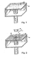
- the layer or film of particulate material 20 may be formed in any suitable manner, for example using a counter-roller.
- the particulate material 20 applied to the surface includes an insoluble filler material, a soluble filler material, and a transition metal catalyst.
- the particulate material 20 may also include a pigment and/or a processing aid material.
- an ink-jet style nozzle 28 delivers a fluid binder 26 to at least a portion 30 of the layer or film of the particulate mixture 20 in a two-dimensional pattern.
- the fluid binder 26 delivered to the particulate material 20 includes a (meth)acrylate functional monomer, an allylic functional monomer/oligomer, and an organic hydroperoxide.
- the fluid binder 26 may also include a surfactant, an accelerator, and/or a (meth)acrylate functional oligomer.
- the fluid binder 26 is delivered to the layer or film of particulate material 20 in any predetermined two-dimensional pattern (circular, in the figures, for purposes of illustration only), using any convenient mechanism, such as a drop-on-demand (DOD) printhead driven by software in accordance with article model data from a computer-assisted-design (CAD) system.
- DOD drop-on-demand
- CAD computer-assisted-design
- the first portion 30 of the particulate material activates the fluid binder 26, causing the fluid binder to initiate polymerization into a solid that adheres together the particulate mixture to form a conglomerate of the particulate material 20 (powder) and fluid binder 26.
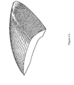
- the conglomerate defines an essentially solid circular layer that becomes a cross-sectional portion of an intermediate article 38 (see, e.g., Figures 3 and 4 ).
- activates is meant to define a change in state in the fluid binder 26 from essentially stable to reactive. This definition encompasses the decomposition of the organic hydroperoxide in the fluid binder 26 once in contact with the transition metal in the particulate material 20.
- the fluid When the fluid initially comes into contact with the particulate mixture, it immediately flows outwardly (on a microscopic scale) from the point of impact by capillary suction, dissolving the soluble filler within a time period, such as 30 seconds to one minute.
- a typical droplet of fluid binder has a volume of about 50 picoliters (pl), and spreads to a diameter of about 100 micrometer ( ⁇ m) after coming into contact with the particulate mixture.
- the fluid binder dissolves the soluble filler, the fluid viscosity increases dramatically, arresting further migration of the fluid from the initial point of impact.
- the fluid with soluble filler dissolved therein flows and adheres to the insoluble filler, forming adhesive bonds between the insoluble filler particulate material.
- the fluid binder is capable of bonding together an amount of the particulate mixture that is several times the mass of a droplet of the fluid.
- the adhesive bonds harden, joining the insoluble filler particulate material and, optionally, pigment into a rigid structure, which becomes a cross-sectional portion of the final article 40.
- any dry particulate mixture 32 that was not exposed to the fluid remains loose and free-flowing on the movable surface 22.
- the dry particulate mixture is typically left in place until formation of the intermediate article 38 is complete. Leaving the dry, loose particulate mixture in place ensures that the intermediate article 38 is fully supported during processing, allowing features such as overhangs, undercuts, and cavities to be defined and formed without the need to use supplemental support structures.
- the movable surface 22 is indexed downwardly, in an embodiment, and the process is repeated.
- a second film or layer of the particulate mixture is then applied over the first layer, covering both the rigid first cross-sectional portion, and any proximate loose particulate mixture.
- a second application of fluid binder follows in the manner described above, dissolving the soluble filler and forming adhesive bonds between at least a portion of the previous cross-sectional formed portion, the insoluble filler particulate material, and, optionally, pigment of the second layer, and hardening to form a second rigid cross-sectional portion added to the first rigid cross-sectional portion of the final article.
- the movable surface 22 is again indexed downward.
- the previous steps of applying a layer of particulate mixture, including the soluble filler, applying the fluid binder, and indexing the movable surface 22 downward are repeated until the intermediate article 38 is completed.
- the intermediate article 38 may be any shape, such as cylindrical. At the end of the process, only a top surface 34 of the intermediate article 38 is visible in the container 24.
- the intermediate article 38 is typically completely immersed in a surrounding bed 36 of dry and loose particulate material.
- an article could be formed in layers upward from an immovable platform, by successively depositing, smoothing, and printing a series of such layers.
- the dry and loose particulate material may be removed from the intermediate article 38 by pressurized air flow or a vacuum.
- a post-processing treatment may be performed, such as heating in an oven, painting, etc. to define a final article 40, having the same shape as intermediate article 38, but with additional desired characteristics, such as a smooth surface appearance, neutral chroma, high lightness, toughness, strength, and flexibility.
- a particulate material suitable for Three Dimensional Printing includes or consists essentially of: insoluble filler 50 - 90 wt% soluble filler 10 - 50wt% pigment 0.0-5 wt% transition metal catalyst 0.01 - 1 wt% processing aids 0.01-2.0 wt%
- a preferred particle size, i.e., diameter, of components of the particulate material is less than about 125 microns and greater than about 30 microns.
- the insoluble filler provides dimensional stability and adhesion for strength of an article formed from the particulate material.
- One suitable insoluble filler for use with embodiments of the invention is glass microspheres.
- the glass microspheres may be made from borosilicate glass with an index of refraction of 1.5 and may be spherical with a particle size distribution ranging from greater than about 20 microns to less than about 125 microns, more preferably between 40 and 90 microns.
- the glass microspheres may be treated with an amino-silane so that the microsphere surface may have an amine functionality and provide better adhesion to a (meth)acrylate based binder.
- Such glass spheres is SPHERIGLASS 2530 CP03, available from PQ Corporation based in Valley Forge, PA. This supplier also offers another glass microsphere product, T-4 SIGN BEADS, having an index of refraction of 1.9 that offers better light scattering to create a more neutral and lighter color than that of SPHERIGLASS 2530 CP03.
- T-4 SIGN BEADS Another suitable borosilicate glass bead product with an index of refraction of 1.5, but more translucent than Spheriglass 2530 CP03, is GL0179 from Mo-Sci Specialty products, LLC based in Rolla, MO. The clearer product imparts a more neutral color to articles than both the SPHERIGLASS and T-4 SIGN BEAD products, which may be desirable for attaining a wider color gamut.
- insoluble fillers suitable for use with embodiments of the invention include solid glass spheres, hollow glass spheres, solid ceramic spheres, hollow ceramic spheres, potato starch, tabular alumina, calcium sulfate hemihydrate, calcium sulfate dehydrate, calcium carbonate, ultra-high molecular weight polyethylene, polyamide, poly-cyclic-olefins, polyurethane, polypropylene, and combinations thereof.
- the insoluble filler consist mostly of spherical shaped particles with a particle size distribution with 10% less than 30 to 40 microns, with 90% less than 90 to 125 microns, with 50% between 50 to 70 microns.
- Angular, non-spheroid shaped particles with wide particle size distributions with 10% less than 3 to 30 microns, with 90% less than 60 to 90 microns, and with 50% of the particles between 20 to 60 microns are to be avoided or used less than 10% by weight in the particulate material in order to provide low capillary pressure which in turn lowers the amount of distortion.
- the addition of angular shaped particles may decrease the average capillary radius of the particulate material thus increasing capillary pressure and increasing distortion of the final article.
- the contact angle, ⁇ is the angle of contact between a liquid and solid.
- a contact angle of 0° suggest that the fluid will spontaneously wet the entire surface of the solid to which it is applied, while a contact angle greater than 90° suggests that the fluid will not spontaneously spread and wet the surface of the solid to which it is applied.
- Spontaneously used herein is in reference to thermodynamic equilibrium, and does not denote an instance of time.
- the difference of ⁇ sv - ⁇ sl in the numerator of Equation 2 may be defined as the adhesion tension of the solid at the solid-liquid-vapor interfaces. It may be desirable to have this adhesion tension greater than or equal to the surface tension of the fluid at the liquid-vapor interface.
- the adhesion tension may be related to the surface characteristic defined as the critical surface tension by Zisman, which is described in the following paragraphs.
- Equation 1 capillary pressure increases if the average radius of the capillaries decreases and/or if the contact angle increases through an increase of the fluid's surface tension, and/or the adhesion tension of the solid decreases.
- This effect of capillary pressure infiltrating a porous medium may be measured by the Washburn infiltration method.
- the Washburn equation describes the time a fluid takes to infiltrate into and through porous medium.
- the material constant c may be determined by infiltrating a porous medium with a very low surface tension fluid that will have a contact angle of 0° against the solid surface of particles comprising the porous medium.
- n-Hexane is a common fluid used for such purposes, having a surface tension of 18 dynes/cm; it is assumed to have a contact angle of 0° against most solid surfaces. This makes the value of cos ⁇ equal to 1 in Equation 3, thereby making it possible to solve for the material constant c since the fluid properties of n-hexane are known. This leaves one to measure the rate of mass increase of the fluid infiltrating the porous medium over time.
- This mass-time response may be measured by use of a Krüss Processor Tensiometer K100 with accessories for Washburn contact angle measurement, available from KRUSS USA based in Mathews, NC, or by use of a KSV Sigma 70 Tensiometer from KSV Instruments USA based in Monroe, CT.
- a vial of powder is prepared.
- the vial is perforated at a bottom portion, with a piece of porous filter paper preventing the powder from pouring through the perforated bottom.
- the vial filled with powder is attached to a microbalance, and the bottom of the vial is brought into contact to the surface of the fluid, in this case n-hexane.
- Software records the mass increase of the vial over time from the microbalance as the fluid is drawn into the powder in the vial largely by capillary pressure.
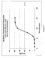
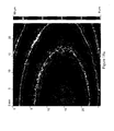
- One may then plot the mass squared over time, which should result in a straight line during the time fluid is infiltrating into the powder in the vial (see Figure 5 , that illustrates a typical response from the Washburn infiltration method to determine the material constant and contact angle of a fluid against a particulate material).
- the slope may be calculated from that plot, which corresponds to the value of m 2 t in Equation 3. After the slope is calculated, one may solve for the material constant c.
- the Washburn method described above was used to determine the material constant of (i) a particulate material primarily composed of glass microspheres with a particle size distribution in which 10% of the particles have a particle size, i.e., diameter, of less than 50 microns, 50% are less than 70 microns, and 90% are less than 100 microns and (ii) a particulate material primarily composed of glass microspheres with calcium sulfate hemihydrate which is an angular, non-spheroid shape particle with a particle size distribution in which 10% of the particles have a particle size of less than 5 microns, 50% are less than 25 microns, and 90% are less than 70 microns.
- the results are given in Table 1.
- Particulate material consisting primarily of glass microspheres
- Particulate material consisting a 50/50 blend by bulk volume of glass microspheres with calcium sulfate hemihydrate Ingredient % by wt. % bulk volume Ingredient % by wt.
- a comparison of material constants shows a significant difference between the two particulate formulations.
- the particulate material consisting primarily of glass microspheres exhibits a material constant almost six times greater than the particulate material formulation consisting of the 50/50 blend by bulk volume of glass microspheres and calcium sulfate hemihydrates. This difference suggests that the angular grains of the calcium sulfate hemihydrate impart a denser packed particulate material that leads to much smaller average capillary radii.
- the larger material constant of the particulate material consisting primarily of glass microspheres suggest a larger average capillary radius, allowing for a lower capillary pressure and thus would exhibit lower distortions on printed articles.
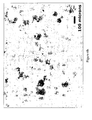
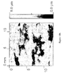
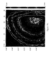
- Figures 6a and 6b magnified images taken from an Olympus SZX12 microscope of both particulate material formulations illustrate the particle distribution of the two materials.
- Figure 6a is a magnified image of the particulate material consisting primarily of glass microspheres and a soluble filler as the secondary component.
- Figure 6b is a magnified image of the particulate material consisting of a 50/50 blend by bulk volume of glass microspheres and calcium sulfate hemihydrates with a soluble filler as the third component.
- the Washburn method may also be utilized to determine the contact angle the fluid binder forms with the particulate material, since the material constant is can be determined for each particulate formulation.
- the fluid binder formulation of Table 2 was used to determine the contact angle the fluid has with each of the above particulate formulations of Table 1: Table 2 Fluid Binder Ingredients % by wt.
- Sartomer SR209 Tetraethylene glycol dimethacrylate 57.50%
- Sartomer SR-506 Isobornyl methacrylate 30.00%
- BYK UV 3500 Surfactant 0.05%
- Table 3 The contact angles given in Table 3 were determined using the fluid binder of Table 2 to infiltrate each of the particulate material samples in a vial.
- Table 3 Particulate material consisting primarily of glass microspheres
- the fluid binder wets the particulate material consisting primarily of glass microspheres better than the formulation containing calcium sulfate hemihydrate because it exhibits a contact angle of zero with the former.
- Articles printed from the particulate material consisting of calcium sulfate hemihydrate along with glass microspheres exhibit distortions such as the cupping of flat rectangular articles as capillary forces pull particles inward in the printed area where fluid binder is applied.
- Articles printed from particulate material formulations consisting primarily of glass microspheres between 70-90% by weight, or 50-75% by bulk volume have consistently resulted in articles with very little to no distortion from capillary forces.
- the soluble filler primarily helps to control the migration of binder through the particulate material, which controls bleed or pooling of fluid binder in selectively printed areas, and also provides extra strength and toughness to the final cured article.
- the soluble filler helps control binder migration of binder by dissolving into the fluid binder deposited in the selective areas to increase the viscosity of the fluid binder that decreases the rate of binder migration.
- Soluble fillers suitable for use with embodiments of the invention include methyl methacrylate polymers, ethyl methacrylate polymers, butyl methacrylate polymers, polyvinylbutyral, and combinations thereof.
- a suitable soluble filler is a solid methacrylate polymer with a glass transition temperature between about 40 and about 60 degrees Celsius and a molecular weight from a range of about 100,000 to about 500,000 g/mol.
- a suitable soluble filler is a polymethylmethacrylate/ethyl methacrylate co-polymer resin such as ELVACITE 2014, available from Lucite International based in Cordova, TN.
- Another suitable resin is a butylmethacrylate/methylmethacrylate copolymer resin such as NEOCRYL B-723, available from NeoResins based in Wilmington, MA.
- the soluble filler may be processed to achieve a particle size distribution where 10% of the particles are less than 20 to 30 microns, and 90% of the particles are less than 80 to 100 microns, and 50% of the particles are between 50 and 70 microns.
- the particulate material may be non-reactive such that it does not swell or dissolve in the fluid binder.
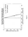
- the effect of a molecular weight of the soluble filler may be measured with a Texture Analyzer TA-XT2i from Stable Micro System based in the United Kingdom.
- This instrument may be used to measure a three-point flexural strength of a bar 5 mm thick, 5.7 mm wide, and 50 mm long created from the application of fluid binder onto the particulate material on a three-dimensional printer, supported on a two-point span spaced at a distance of 40 mm.
- the force to break the test part with the force applied at the center of the 40 mm span may be used to calculate an estimate of flexural strength.
- the distance to break the test part is also recorded which may estimate the amount of strain the bar endures.
- Sigma-Aldrich Light Mineral Oil 0.24% wt. 0.23% wt. 0.16% wt. 0.24% wt. 0.23% wt. 0.13% wt. 0.16% wt. Sigma-Aldrich Cobalt Octoate, 65% in mineral spirits 0.21% wt. 0.10% wt 0.11% wt. 0.21% wt. 0.21% wt. 0.11% wt. 0.10% wt.
- the flexural test bars were printed on a Spectrum Z ® 510 Three Dimensional Printer available from Z Corporation in Burlington, MA modified to use a SM-128 piezoelectric jetting assembly along with an Apollo II Printhead Support Kit both available from FUJIFILM Dimatix based in Santa Clara, CA.
- the flexural test bars were printed applying the fluid binder listed on Table 5 through the SM-128 jetting assembly over the particulate material at a layer thickness of 100 microns.
- the fluid was deposited selectively and uniformly at each layer to occupy 32% by volume of the flexural test part.
- the flexural test parts were allowed to solidify for 1 hour before they were extracted from the build bed of the Spectrum Z510 and placed in a 60°C oven for 12 hours to cure.
- Table 6 summarizes flexural properties of the particulate material compositions that were measured. Referring to Figure 7 , a graphical representation of the results collected is provided. The results suggest that soluble fillers with molecular weights less than 100,000 g/mol exhibit lower flexural properties than soluble fillers with molecular weights greater than 100,000 g/mol.
- the particulate material may include pigments in a concentration of 0.5 - 5% by weight.
- Titanium dioxide is a pigment with a refractive index of 2.4 that may be used, but its listing as a possible IARC carcinogen makes it undesirable for use in an office environment.
- Zinc oxide is an alternative pigment with a refractive index of 2.0, and it is not listed as a carcinogen.
- Zinc oxide available from Sigma-Aldrich based in Milwaukee, WI, imparts the most neutral color over titanium dioxide.
- Other suitable pigments include zinc sulfide, barium sulfate, zirconium silicate, lead carbonate, and hollow borosilicate glass spheres.
- Pigments may also be incorporated and bound into the insoluble filler or soluble filler, which may be advantageous to prevent the particulate material from exhibiting excessive dust and to agglomerate as the unbound pigments may adhere to the processing aids used to control the desired spreading characteristics, causing the particulate formulation to lose its desired flowability characteristics.
- OMNICOLOR UN0005 from Clariant based in Charlotte, NC is white colorant compound of pigment and a resin for injection molded plastics which can be use as an alternative pigment source where the pigment is bound in the resin, reducing the dustiness and maintaining the desired flowability characteristics while providing color.
- This colorant and other types of colorant commonly used in injection molding applications may also be used to color the soluble filler, such as ELVACITE 2014, through melt processing to make a more uniform colored particulate formulation.
- DECOSOFT and DECOSILK are pigmented polyurethane and acrylic microbeads respectively from Microchem based in Erlenback, Switzerland commonly used to make colored or transparent, low gloss, soft-feel coatings. These products may be used as an insoluble filler to impart tougher material properties while imparting the desired color because of the pigment incorporated into the microbead product, thus decreasing the dust and maintaining the desired flowability characteristics.
- the transition metal catalyst may induce the decomposition of the organic hydroperoxide in the fluid binder to generate free radicals and to catalyze the absorption of oxygen for allyllic polymerization.
- Transition metals are metal ions that have multiple oxidation states and can readily lose or gain electrons in the presence of oxidizing or reducing agents, respectively.
- Metal catalysts based on copper, iron, vanadium, manganese titanium, and cobalt are preferred, although other metal catalysts may be used.
- one suitable transition metal catalyst includes cobalt (II) octoate in 65% mineral spirits from Sigma-Aldrich based in St. Louis, Missouri.
- Other suitable metal catalysts include, e.g., cobalt (II) naphthenate, vanadium (II) octoate, manganese naphthenate, and combinations thereof.
- Processing aids may be used to affect particulate material spreading characteristics to achieve a desirable internal angle of friction (see discussion below) and to reduce capillary forces between the particulate material in contact with the fluid binder. Processing aids can further assist in reducing nuisance dust of the particulate material.
- Mineral oil is a typical processing aid that affects the flowability of the particulate material; it may be used from 0.01% to 1% by weight in the particulate formulation. The particulate material remains substantially dry upon the inclusion of this small amount of mineral oil.
- Mineral oil e.g., from Sigma-Aldrich, may provide a good balance of particulate cohesion and low plasticizing of the soluble filler without reducing capillary pressure.
- Hydrogenated hydrocarbon resins such as REGALREZ 1094 from Eastman based in Kingsport, TN, are tackifiers that may be used as processing aid to increase the viscosity of the mineral oil and may be 0.01 to 2% by wt of the particulate material.
- the hydrocarbon resin increases the viscosity of the processing aid that imparts a unique cohesiveness and flowability characteristic, whereby the particulate material, under shear from a counter-rolling spreader rod, becomes a free-flowing powder. The desired cohesion is restored while at rest to resist dragging while successive layers are being spread.
- the increase in viscosity assists in the fracture of the inter-particle adhesive necks of fluid that the processing aids create to control flowability characteristics under shear; the adhesive necks of fluid then slowly reform while the particulate material is at rest.
- the inter-particular adhesive necks of fluid that lower viscosity processing aid imparts do not fracture as easily under shear because the processing aids are allowed to flow more easily and faster to reform the inter-particular adhesive necks of fluid.
- processing aids suitable for use with embodiments of the invention include, e.g., propylene glycol di(caprylate/caprate), petroleum jelly, propylene glycol, di-isobutyl phthalate, di-isononyl phthalate, polyalkyleneoxide modified heptamethyltrisiloxanes, polyalkyleneoxide modified polydimethylsiloxanes, secondary alcohol ethoxylates, hydrogenated hydrocarbon resins, and combinations thereof.
- a surfactant is a typical processing aid that may be used in conjunction with mineral oil to reduce the capillary forces between the particulate material in contact with the fluid binder by increasing the critical surface tension of the particulate material.
- Surfactants may be used in a range of 0 to 1% by weight of the particulate material.
- Silicone surfactants such as SILWET L-7608 or COATOSIL L-77 from General Electric Company based in Wilton, CT having a reported capability of reducing surface tension of water to less than 25 dynes/cm, may effectively reduce capillary forces between particles of the particulate material in contact with the non-aqueous fluid binder.
- Secondary ethoxylated alcohols hydrocarbon surfactants such as TERGITOL 15-S-7 and TERGITOL-15-S-5 from DOW based in Midland, MI, also may effectively reduce capillary forces between particles of the particulate material in contact with the non-aqueous fluid binder.
- the effect of the surfactant increasing the surface energy of the particulate material may be measured using the Washburn method describe earlier by infiltrating a particulate material formulation with a series of liquid solutions with varying surface tension values.
- the contact angles, ⁇ are determined for each surface tension.
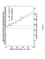
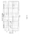
- the cos ⁇ values are plotted against the surface tension values to construct a Zisman plot.
- This test was performed on the formulations listed in Table 7. See Figures 8 (particulate material with paraffinic oil processing aid) and 9 (particulate material with a paraffinic oil and surfactant blend processing aid).
- One preferred embodiment of a fluid binder suitable for Three Dimensional Printing includes or consists essentially of: (meth)acrylate monomer 40 - 90 wt% (meth)acrylate oligomer 0 - 40 wt% allyl ether functional monomer/oligomer 5 - 25 wt% organic hydroperoxide 0.5 - 5 wt% accelerator 0 - 2 wt% surfactant 0 - 1 wt%
- the (meth)acrylate (i.e., methacrylate and/or acrylate) monomers and oligomers provide the properties of strength and flexibility.
- Such monomers and oligomers may be procured from Sartomer based in Exton, PA.
- the allyl ether monomer/oligomer provides the oxidative drying of the binder on the surface of the article so that the surface is not tacky.
- Allyl ether monomers may be procured from Perstorp based in Sweden.
- Suitable oligomers with allyl functionality may be obtained from Sartomer, who offers CN-9101 urethane allyl functional oligomer.
- Bomar Specialty Chemicals based in CT offers BXI-100, a poly-allyl-glycidyl-ether oligomer, another suitable allyl functional oligomer.
- the organic hydroperoxide is the free radical initiator for the anaerobic polymerization of the (meth)acrylate monomers and oligomer, and the aerobic polymerization of the allylic monomer/oligomer.
- a suitable organic hydroperoxide is cumene hydroperoxide available as LUPEROX CU90 from Arkema based in Philadelphia, PA.
- the transition metal catalyst induces the decomposition of the organic hydroperoxide, thus providing free radicals for subsequent reactions and catalyzes the absorption of oxygen at the surface.
- Another organic hydroperoxide suitable for use with some embodiments is tert-butyl hydroperoxide, is available as T-HYDRO from Lyondell Chemical Company based in Houston Texas.
- the surfactant is a preferred additive in the formulation of the fluid binders used in Three Dimensional Printing to reduce the surface tension of the binder so that the surface tension is equal to or less than the critical surface tension of the particulate material, such that the contact angle of the fluid binder against the particulate material is less than 25°, but preferably closer to if not equal to 0°.
- This allows the fluid binder to wet out onto the particulate material without creating large capillary forces that may cause (i) fissuring at points where the printed area on the particulate material splits apart and (ii) balling where the fluid binder sits on the surface of the particulate material. Both of these occurrences may cause surface defects on the bottoms of flat surfaces of printed articles.
- Figure 10a illustrates an example of good wetting behavior with contact angles less than 25° when the binder has a surface tension at or below a critical surface tension of the particulate material and wets smoothly over the particulate material.
- the critical surface tension of the particulate material may be greater than 20 dynes/cm.
- Figure 10b illustrates an example of poor wetting behavior with contact angles greater than 25° when the binder has a surface tension greater than the critical surface tension of the particulate material causing the binder to wet irregularly over the particulate material and creating fissures.
- a suitable surfactant is a polyether modified acryl functional polydimethylsiloxane surfactant available as BYK UV 3500 from BYK Chemie based in Hartford, CT. This surfactant is a wetting agent commonly used in UV curable coatings to ensure a smooth finish on substrates and, when used at 0.05% by weight in the fluid formulation, reduces the surface tension to about 25 +/- 1 dynes/cm.
- Other suitable surfactants may include fluorinated surfactants such as the ZONYL surfactants available from DuPont, which can reduce the surface tension of the fluid binder down to 20 dynes/cm.
- Fluid formulations of various embodiments of the instant invention are somewhat similar to anaerobic adhesive formulations commonly known as "threadlockers” such as LOCTITE 290 from Loctite based in Rocky Hill, CT and which is disclosed by Krieble in U.S. Patent No. 2,895,950 assigned in 1957 to American Sealants Company based in Hartford, CT, incorporated herein by reference in its entirety. Aerobically curing formulations using allyl ethers are also known to the art, as described by Cantor et al. in U.S. Patent No. 5,703,138 assigned to Dymax Corporation, incorporated herein by reference in its entirety.
- FUJIFILM Dimatix based in Santa Clara CA has a published application note describing the application of LOCTITE 290 adhesive through one of their piezo jetting assemblies to accurately deliver adhesive to a substrate.
- these formulations do not include a surfactant.
- the fluid adhesive products described in these references do not have the proper surface tension requirements needed for proper wetting, if they were applied onto the particulate material as described in various embodiments of the instant invention. These materials are not intentionally designed to have a surface tension lower than that of the substrate to which they are to be applied, thereby achieving a contact angle of less than 25 degrees. This can be demonstrated by using the Washburn method with the following particulate formulation (Table 8) and binder formulations (Tables 9 and 10).
- Table 8 Particulate material prepared with a mineral oil and surfacant processing aid Ingredient % by wt. % bulk volume MO-SCI GL0179 glass microspheres 83.85% ⁇ 66% Lucite Elvacite 2014 15.73% ⁇ 34% Sigma-Aldrich Light Mineral Oil 0.18% Nil DOW TERGITOL 15-S-5 0.18% Nil Sigma-Aldrich Cobalt Octoate, 65% in Mineral Spirits 0.06% Nil Table 9 Fluid Binder Ingredients % by wt.
- the high contact angle LOCTITE 290 has on the particulate material formulation indicates that this product would not wet out properly onto the particulate material when applied during Three Dimensional Printing, and would create articles with rough, irregular bottom surfaces, having defects similar to the defects illustrated in Figure 10b .
- a fluid binder properly formulated to have a surface tension lowered to at least 25 dynes/cm so that it has a contact angle less than 25° and close to, if not equal to 0° will wet out the powder properly, resulting in a smooth bottom facing surface with less edge curling distortion, as is exhibited in Figure 10a .
- Surfactants may be used in photocurable inkjet fluid formulation, as disclosed, for example, in U.S. Patent No. 6,433,038 to Tanabe , where surfactants are used to stabilize dyes and pigments in the disclosed fluid inkjet formulation.
- Huo et al. in an international patent application PCT/US2005/025074 disclose the use of surfactants to improve wettability of the fluid over non-porous plastic substrates and to control the dynamic surface tension of the fluid for faster meniscus reformation at the nozzle of a DOD device during jetting. These formulations do not use surfactants to decrease the capillary pressure exerted by the fluid when applied on a particulate material, as disclosed herein.
- FIG. 12 Another exemplary formulation listed on Table 12 shows a particulate powder formulation with a lower critical surface tension than critical surface tensions of particulate formulations disclosed on Table 7.
- Figure 11 is a Zisman plot of a particulate material including a tackifier processing aid.
- the surface tension of the fluid binder is essentially at the critical surface tension of the particulate material, and therefore results in a contact angle equal to 0°.
- the contact angle may be greater than 0° and possibly less than 25° if the critical surface tension is 2 dynes/cm less than the surface tension of the binder. This upper limit of a contact angle is estimated from Equation 2 by dividing the critical surface tension of the solid by the surface tension of the fluid.
- the contact angle of the fluid binder against both of the particular material listed in Table 12 was determined from the Washburn method to have an average cos ⁇ value of 1.02 +/- 0.05 at 99% confidence, which would result in a contact angle between 0° and 14° within the 99% confidence interval range of the cos ⁇ value.
- This fluid binder when applied to the particulate material disclosed in Table 12, results in proper wetting of the fluid binder over the particulate material to impart a smooth bottom finish, as illustrated in Figure 10a .
- Table 12 Particulate Material Ingredients % by wt.
- kits may include various combinations of the substantially dry particulate material and a fluid binder described above.
- a kit may include (i) a substantially dry particulate material comprising an insoluble filler, a soluble filler, and a transition metal catalyst, and (ii) a fluid binder including a (meth)acrylate monomer, at least one of an allyl ether functional monomer or an allyl ether functional oligomer, and an organic hydroperoxide.
- the fluid binder may have a contact angle of less than 25° on the particulate material.
- the fluid binder may include about 40% - 95% by weight of the (meth)acrylate monomer, about 5 - 25% by weight of the allyl ether functional monomer/oligomer, and about 0.5 - 5% by weight of the organic hydroperoxide.
- the fluid binder may also include 0% - 1% by weight of surfactant.
- the fluid binder may include a (meth)acrylate oligomer, e.g., about 10 - 40% by weight of the (meth)acrylate oligomer.
- the fluid binder may also include a first accelerator such as dimethylacetoacetamide, e.g., up to about 2% by weight of the first accelerator.
- a 1 mm penetration hardening rate of the substantially dry particulate material upon application of the fluid binder may be e.g., 0.01/min to 1.0 /min.
- the dry particulate material may include a pigment and/or a processing aid.
- An article may be defined by selectively printing the fluid binder over particulate material.
- the fluid binder includes a (meth)acrylate monomer, a (meth)acrylate oligomer, an allyl ether functional monomer and/or oligomer, and organic hydroperoxide and, optionally, a first accelerator.
- the amount of binder deposited onto the particulate layer can range from 20% to 35% of the volume of the selectively printed area at a predetermined layer thickness between 50 to 175 microns, and more preferably between 75 and 125 microns.
- the particulate material includes a plurality of adjacent particles, comprising a transition metal catalyst and, at least one of an insoluble filler, a soluble filler, a pigment, a second accelerator, and a processing aid.
- the transition metal catalyst induces decomposition of the organic hydroperoxide to generate free radicals.
- the free radicals initiate anaerobic polymerization of the (meth)acrylate monomer and oligomer, and aerobic polymerization of the allyl ether functional monomer/oligomer.
- the complete polymerization, i.e., cure, of the article may take between about 30 minutes and about 6 hours to complete after the formation of a solid article, after all the layers of the article have been printed.
- the curing happens substantially instantaneously, so that the printed article may be removed from the printer as soon as the printing is complete.
- Sano in U.S. Patent Application Publication No. 2007/0007698 and U.S. Patent 7,300,613 , describes primarily the use of photocurable resins applied onto powder via a drop-on-demand printhead as well as two component curing strategies such as epoxy-amine thermosetting resins; Kramer, et al, in U.S. patent 7,120,512 assigned to Hewlett-Packard in Houston, TX, also disclose the use of photocurable resins applied over powder using a drop-on-demand printhead, as well as alternative embodiments of two component systems.
- photocurable fluid binders are generally not suitable for Three Dimensional Printing because of the instantaneous curing leading to immediate shrinkage, which leads to the first 2 to 10 layers of selectively printed areas to curl and warp out of the plane of the build bed to be eventually dragged and displaced in or completely off the build bed.
- Sano suggests the use of photocurable resins that polymerize via ring opening mechanism such as epoxides and oxetanes to limit the degree of shrinkage.
- ring opening mechanism such as epoxides and oxetanes
- Patel, et al. have international applications published through the World Intellectual Property Organization (publication numbers WO 03/016030 and WO 02/064354 A1 ) with Vantico as the assignee (now owned by Hunstman based in TX) that describe the use of various embodiments of applying photocurable resins and two-component resins.
- Three Dimensional Printing apparatuses and methods using ultraviolet cure are disclosed by Yamane, et al, in U.S. Patent 5,149,548 assigned to Brother Kogyo Kabushiki Kaisha in Japan, which describes the use of a two part curable resin utilizing microcapsules encapsulating a curing agent deposited with a drop-on-demand printhead. The microcapsules are broken upon exposure to ultraviolet light.
- a user typically waits the above-indicated time after the article is printed before removing the article from the printer.
- the article may be heated to a range of about 40°C to about 100°C to accelerate the aerobic cure at the surface of the article.
- Heat may be supplied through convection, conduction, infra-red radiation, microwave radiation, radio-wave radiation, or any other suitable method.
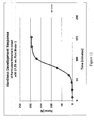
- the cure rate between a photocurable binder and the current embodiment may be illustrated by comparing the hardening rate by measuring the force it takes to penetrate 1 mm into the surface of a mass mixture consisting of fluid binder and particulate material with a 0.5 inch spherical probe.
- Such a test of a 1 mm penetration hardening rate may be performed with a Texture Analyzer TA-XT2i with a P/0.5S stainless steel spherical probe from Stable Micro System based in the United Kingdom.
- the following particulate material system used in this test is listed in Table 13. Table 13 Ingredient % by wt. % by wt. % by wt.
- the binder formulation used in this test is given in Table 14.
- Sartomer SR209 Tetraethylene glycol dimethacrylate 57.50% 57.45% 69%
- Sartomer SR-506 Isobornyl methacrylate 30.00% 30.00% 29%
- the hardness development was measured at 15 minute intervals using the spherical probe to measure the force to penetrate 1 mm into the mixture contained in the polypropylene dish.
- the mixture in the polypropylene dish was exposed to 30 seconds of ultraviolet light using a RC250B Flash Curing unit from XENON Corporation based in Wilmington, MA.
- the hardness development of the photocurable example is the plot of the penetration force at 30 seconds.
- Figure 12 shows the typical development response collected, i.e., of particulate material A mixed with a fluid binder 1. The natural logarithm of the force is taken to determine the hardening rate from the slope of the transformed data before the force plateaus.
- a transformed plot of Figure 12 plots the natural logarithm of the force measured against time.
- Table 16 lists hardness rates determined from the data collected.
- the photocurable example exhibits a hardness development rate on the order of 1000X greater than the current embodiment.
- This hardness rate is related to the rate of conversion of double bonds on the (meth)acrylate monomer.
- the conversion of the carbon-to-carbon double bonds into single carbon-to-carbon bonds with other monomers decreases the amount of free volume in the fluid binder as it polymerizes.
- the instantaneous conversion of monomers into a polymer in a photocurable fluid binder causes an instantaneous shrinkage upon exposure to ultraviolet light, which forces selectively printed areas to curl and warp out of the plane of the build bed, causing the selectively printed areas to be dragged and displaced as successive layers are spread.
- the slower hardening rate of some embodiments relates to a slower conversion rate and where selectively printed areas do not exhibit the immediate distortion of curling and warping out of the plane of the build bed to successively print layer upon layer without dragging or displacement of features on an article.
- the 1 mm penetration hardening rate is between 0.01/minute and 1.0/minute.
- Strength development of the current embodiment can also be measured using the earlier described Texture Analyzer to measure a three-point flexural strength of a bar 5 mm thick, 5.7 mm wide, and 50 mm long, supported on a two-point span spaced at a distance of 40 mm.
- the force to break the test part when applied at the center of the 40 mm span can be used to calculate an estimate of flexural strength.
- the current embodiment can typically exhibit flexural strengths between 10 and 20 MPa after 60 minutes, and 15 to 25 MPa and greater after 120 minutes in the build bed after the last layer of the article completed printing. This strength represents mostly the anaerobic strength development that occurs within the article, while the aerobic curing occurring within 200 microns from the surface of the article is still ongoing at a slower rate.
- the article may exhibit a tacky surface at 60 minutes, but may exhibit a durable and handle-able strength.
- Figure 14 shows the typical response of aerobic cure when measured using the test part 1500 shown in Figure 15 .
- the particulate material and fluid binder formulations listed in Table 17 were used to conduct this test. Table 17 Particulate Material Ingredients % by wt.
- Anaerobic polymerization occurs where no oxygen is present in the interior portions of the three dimensional articles being created, e.g., at depths greater than about 0.2 mm from the surface of the printed article. Aerobic polymerization occurs at the surface and at a depth into which oxygen is capable of diffusing.
- a simplified kinetic mechanism for free radical polymerization may be represented by the following steps: Radical Generation Initiator ⁇ Free Radicals Initiation Free radical + Monomer ⁇ Radical Monomer Propagation Radical Monomer + Monomer ⁇ Radical Polymer Termination Radical Polymer + Radical Polymer ⁇ Polymer
- Anaerobic radical generation occurs when the hydroperoxide is decomposed by a transition metal capable of oxidizing and reducing its valence charge, such as cobalt. This is represented by the following mechanism: Co +2 + ROOH ⁇ Co +3 + RO• + OH-
- the oxidized Co +3 ion can then be reduced to Co +2 via Co +3 + ROOH ⁇ Co +2 + ROO• + H + and/or Co +3 + OH - ⁇ Co +2 + •OH
- RO•, ROO•, and •OH are radicals species that can react with a monomer or oligomer species and start polymerization.
- the RO• and •OH radicals are more efficient under anaerobic conditions with (meth)acrylate functional monomers and oligomers.
- Oxygen may react with these radical species to form weak radicals, or may be scavenged by free radical inhibitors that use oxygen to function, such as the most common type of inhibitors based on hydroquinones.
- the anaerobic polymerization continues to propagate under anaerobic conditions until terminated.
- Transition metals like cobalt also assist in the auto-oxidative drying (aerobic curing) of the allyl ether functional monomers or oligomers by increasing oxygen absorption at the surface.
- a radical center is created at the place of allylic hydrogen, where the hydrogen is abstracted by radicals species from the organic hydroperoxide; or with the assistance of cobalt, the allylic hydrogen is abstracted by oxygen.
- the radical center of the allyl group now reacts further with oxygen to make a peroxide radical.
- the peroxide radical species can add to double bonds of (meth)acrylate functional groups or other allyl groups, terminate with other radicals, or abstract further hydrogen atoms from monomers, oligomers, or the propagating polymer.
- the result of this aerobic mechanism is a highly crosslink polymer network that forms a non-tacky surface.
- compositions relate to control of the flow properties of the build material in Three Dimensional Printers.
- the three principal methods are the addition of liquid "processing aids," control of grain size distribution, and the addition of solid fillers that contribute to the frictional behavior of the build material.
- Many candidate materials have been disclosed previously, for example, in U.S. Patent Publication Number 2005/0003189 , the disclosure of which is incorporated herein by reference in its entirety.
- Some mechanical properties of dry particulate build materials are disclosed in the following discussion that are particularly suited for use in Three Dimensional Printing, especially in contrast to other formulations of similar materials for other uses that do not require special flow characteristics of the raw materials.
- a method that may be used to quantify a particulate material's suitability for Three Dimensional Printing includes placing 1 liter in bulk volume of a particulate material in a metal cylinder with an inside dimension of 6.1 inches, and inside height of 6.2 inches so that the height of the powder is between 2.5 to 3.0 inches when the cylinder is capped with a transluscent cover and laid on its side (i.e., the height of the cylinder is horizontal). The drum is then slowly rolled with a rotational velocity of 2.5 rotations/min +/- 0.5 rotations/min until the powder reaches an angle where it avalanches upon itself.
- the angle, ⁇ is the internal angle of friction that particulate material has under these particular test conditions at a room temperature between 65 to 75°F.
- Various particulate materials known to have good and bad spreading characteristics are compared using this test method, and desirable range of internal angles of friction were determined.
- Table 18 summarizes the particulate material compositions that were measured. Referring to Figure 16 , a graphical representation of the results collected is provided.
- Figures 17a and 17b compare surface finish scans from a VIKING laser profilometer from Solarius. As one may expect, a particulate material with an internal angle of friction that is between 40° and 70° ( Figure 17a ) provides a smoother finish than a particulate material with an internal angle of friction greater than 70° ( Figure 17b ) where the powder is too cohesive to spread an even layer of particulate material, resulting in an article that has very rough and uneven surface finish.
- Figure 17c is a CAD drawing of the formed part illustrated in Figures 17a and 17b .
- Figures 18a and 18b compare surface finish scans from a VIKING laser profilometer from Solarius. As one may expect, a particulate material with an internal angle of friction that is between 40° and 70° ( Figure 18a ) provides a smoother finish than a particulate material with an internal angle of friction less than 40° ( Figure 18b ) where the powder is too flowable and unable to resist the spreading forces causing previous printed layers to be displaced, resulting in an article that has a rough and uneven surface finish, or even artifacts missing from the surface of the article because they were displaced.
- Figure 18c is a CAD drawing of the formed part illustrated in Figures 18a and 18b .
- This test is a fairly useful technique for identifying relative performance properties between different candidate materials.
- the preferred method for evaluating flow properties of candidate build materials during formal optimization after the initial selection period is to test samples of the material on a working three dimensional printer. Certain pathological geometries are known to those experienced in the art, and they can be evaluated either qualitatively or quantitatively.
- One particularly useful part for observing stability during spreading is a flat plate studded with pegs that are oriented downward during the build. During printing, the earliest layers addressed are a series of disconnected patches that are relatively free to shift in the build material. After these have been formed, a plate is printed that joins all of the pegs together in a single object. One can easily examine whether the pegs are uniform and straight, and one can evaluate the quality of spreading on that basis.
- compositions and parameters listed herein are meant to be exemplary and actual compositions and parameters depend upon the specific application for which the methods and materials of the present invention are used. It is, therefore, to be understood that the foregoing embodiments are presented by way of example only and that, within the scope of the appended claims and equivalents thereto, the invention may be practiced otherwise than as specifically described.
Claims (12)
- Kit, umfassend:ein trockenes teilchenförmiges Material, umfassend:einen unlöslichen Füllstoff;einen löslichen Füllstoff; undeinen Übergangsmetallkatalysator; undein flüssiges Bindemittel, umfassend:ein (Meth)acrylat-Monomer; undein organisches Hydroperoxid;dadurch gekennzeichnet, dass das flüssige Bindemittel ein Allyletherfunktionelles Monomer oder ein Allylether-funktionelles Oligomer umfasst.
- Kit gemäß Anspruch 1, wobei das flüssige Bindemittel etwa 40 bis 95 Gew.-% des (Meth)acrylat-Monomers, etwa 5 bis 25 Gew.-% des Allylether-funktionellen Monomers/Oligomers und etwa 0,5 bis 5 Gew.-% des organischen Hydroperoxids umfasst.
- Kit gemäß Anspruch 1, wobei der Kontaktwinkel des flüssigen Bindemittels kleiner als 25° ist, wenn es sich in Kontakt mit dem teilchenförmigen Material befindet.
- Kit gemäß Anspruch 1, wobei die Härtungsgeschwindigkeit des trockenen teilchenförmigen Materials bei 1 mm Penetration nach Auftragung des flüssigen Bindemittels aus einem Bereich von 0,01/min bis 1,0/min ausgewählt ist.
- Kit gemäß Anspruch 1, wobei das flüssige Bindemittel weiterhin ein (Meth)acrylat-Oligomer umfasst.
- Kit gemäß Anspruch 5, wobei das flüssige Bindemittel 10 bis 40 Gew.-% des (Meth)acrylat-Oligomers umfasst.
- Kit gemäß Anspruch 1, wobei das flüssige Bindemittel weiterhin ein Tensid umfasst.
- Kit gemäß Anspruch 1, wobei das trockene teilchenförmige Material weiterhin ein Pigment und/oder ein Verarbeitungshilfsmittel umfasst.
- Kit gemäß Anspruch 1, wobei das teilchenförmige Material 50 bis 90 Gew.-% des unlöslichen Füllstoffs, 10 bis 50 Gew.-% des löslichen Füllstoffs und 0,01 bis 0,5 Gew.-% des Übergangsmetallkatalysators umfasst.
- Kit gemäß Anspruch 1, wobei der unlösliche Füllstoff aus der Gruppe ausgewählt ist, die aus massiven Glaskügelchen, hohlen Glaskügelchen, massiven Keramikkügelchen, hohlen Keramikkügelchen, Kartoffelstärke, Tabulartonerde, Calciumsulfat-Halbhydrat, Calciumsulfat-Dihydrat, Calciumkarbonat, ultrahochmolekularem Polyethylen, Polyamid, Polycycloolefinen, Polyurethan, Polypropylen und Kombinationen davon besteht.
- Kit gemäß Anspruch 1, wobei der lösliche Füllstoff aus der Gruppe ausgewählt ist, die aus Methylmethacrylat-Polymeren, EthylmethacrylatPolymeren, Butylmethacrylat-Polymeren, Polyvinylbutyral und Kombinationen davon besteht.
- Kit gemäß Anspruch 1, wobei der Übergangsmetallkatalysator aus der Gruppe ausgewählt ist, die aus Cobalt(II)octoat, Cobalt(II)naphthenat, Vanadium(II)octoat, Mangannaphthenat und Kombinationen davon besteht.
Priority Applications (1)
| Application Number | Priority Date | Filing Date | Title |
|---|---|---|---|
| EP13175521.7A EP2664442B1 (de) | 2006-12-08 | 2007-12-07 | Dreidimensionales Druckmaterialsystem |
Applications Claiming Priority (2)
| Application Number | Priority Date | Filing Date | Title |
|---|---|---|---|
| US87373006P | 2006-12-08 | 2006-12-08 | |
| PCT/US2007/025075 WO2008073297A2 (en) | 2006-12-08 | 2007-12-07 | Three dimensional printing material system and method using peroxide cure |
Related Child Applications (2)
| Application Number | Title | Priority Date | Filing Date |
|---|---|---|---|
| EP13175521.7A Division-Into EP2664442B1 (de) | 2006-12-08 | 2007-12-07 | Dreidimensionales Druckmaterialsystem |
| EP13175521.7A Division EP2664442B1 (de) | 2006-12-08 | 2007-12-07 | Dreidimensionales Druckmaterialsystem |
Publications (2)
| Publication Number | Publication Date |
|---|---|
| EP2089215A2 EP2089215A2 (de) | 2009-08-19 |
| EP2089215B1 true EP2089215B1 (de) | 2015-02-18 |
Family
ID=39409817
Family Applications (2)
| Application Number | Title | Priority Date | Filing Date |
|---|---|---|---|
| EP13175521.7A Active EP2664442B1 (de) | 2006-12-08 | 2007-12-07 | Dreidimensionales Druckmaterialsystem |
| EP07862625.6A Active EP2089215B1 (de) | 2006-12-08 | 2007-12-07 | Dreidimensionales druckmaterialsystem |
Family Applications Before (1)
| Application Number | Title | Priority Date | Filing Date |
|---|---|---|---|
| EP13175521.7A Active EP2664442B1 (de) | 2006-12-08 | 2007-12-07 | Dreidimensionales Druckmaterialsystem |
Country Status (7)
| Country | Link |
|---|---|
| US (2) | US7905951B2 (de) |
| EP (2) | EP2664442B1 (de) |
| JP (1) | JP5189598B2 (de) |
| KR (1) | KR101407801B1 (de) |
| CN (1) | CN101568422B (de) |
| HK (1) | HK1135065A1 (de) |
| WO (1) | WO2008073297A2 (de) |
Families Citing this family (115)
| Publication number | Priority date | Publication date | Assignee | Title |
|---|---|---|---|---|
| JP4624626B2 (ja) | 1999-11-05 | 2011-02-02 | ズィー コーポレイション | 材料システム及び3次元印刷法 |
| KR101407801B1 (ko) | 2006-12-08 | 2014-06-20 | 3디 시스템즈 인코오퍼레이티드 | 과산화물 경화를 사용하는 3차원 인쇄 물질 시스템 및 방법 |
| EP2109528B1 (de) * | 2007-01-10 | 2017-03-15 | 3D Systems Incorporated | Dreidimensionales druckmaterialsystem mit verbesserter farb- und geräteleistung sowie erhöhter bedienerfreundlichkeit und verfahren zu dessen benutzung |
| WO2008103450A2 (en) | 2007-02-22 | 2008-08-28 | Z Corporation | Three dimensional printing material system and method using plasticizer-assisted sintering |
| US10226919B2 (en) | 2007-07-18 | 2019-03-12 | Voxeljet Ag | Articles and structures prepared by three-dimensional printing method |
| DE102007050953A1 (de) | 2007-10-23 | 2009-04-30 | Voxeljet Technology Gmbh | Vorrichtung zum schichtweisen Aufbau von Modellen |
| US8067305B2 (en) | 2008-09-03 | 2011-11-29 | Ultratech, Inc. | Electrically conductive structure on a semiconductor substrate formed from printing |
| DE102010006939A1 (de) | 2010-02-04 | 2011-08-04 | Voxeljet Technology GmbH, 86167 | Vorrichtung zum Herstellen dreidimensionaler Modelle |
| DE102010013732A1 (de) | 2010-03-31 | 2011-10-06 | Voxeljet Technology Gmbh | Vorrichtung zum Herstellen dreidimensionaler Modelle |
| DE102010014969A1 (de) | 2010-04-14 | 2011-10-20 | Voxeljet Technology Gmbh | Vorrichtung zum Herstellen dreidimensionaler Modelle |
| DE102010015451A1 (de) | 2010-04-17 | 2011-10-20 | Voxeljet Technology Gmbh | Verfahren und Vorrichtung zum Herstellen dreidimensionaler Objekte |
| JP5890990B2 (ja) | 2010-11-01 | 2016-03-22 | 株式会社キーエンス | インクジェット光造形法における、光造形品形成用モデル材、光造形品の光造形時の形状支持用サポート材および光造形品の製造方法 |
| DE102010056346A1 (de) | 2010-12-29 | 2012-07-05 | Technische Universität München | Verfahren zum schichtweisen Aufbau von Modellen |
| DE102011007957A1 (de) | 2011-01-05 | 2012-07-05 | Voxeljet Technology Gmbh | Vorrichtung und Verfahren zum Aufbauen eines Schichtenkörpers mit wenigstens einem das Baufeld begrenzenden und hinsichtlich seiner Lage einstellbaren Körper |
| US9156999B2 (en) * | 2011-07-28 | 2015-10-13 | Hewlett-Packard Development Company, L.P. | Liquid inkjettable materials for three-dimensional printing |
| DE102011111498A1 (de) | 2011-08-31 | 2013-02-28 | Voxeljet Technology Gmbh | Vorrichtung zum schichtweisen Aufbau von Modellen |
| US20130101729A1 (en) * | 2011-10-21 | 2013-04-25 | John J. Keremes | Real time cap flattening during heat treat |
| DE102012004213A1 (de) | 2012-03-06 | 2013-09-12 | Voxeljet Technology Gmbh | Verfahren und Vorrichtung zum Herstellen dreidimensionaler Modelle |
| DE102012010272A1 (de) | 2012-05-25 | 2013-11-28 | Voxeljet Technology Gmbh | Verfahren zum Herstellen dreidimensionaler Modelle mit speziellen Bauplattformen und Antriebssystemen |
| DE102012012363A1 (de) | 2012-06-22 | 2013-12-24 | Voxeljet Technology Gmbh | Vorrichtung zum Aufbauen eines Schichtenkörpers mit entlang des Austragbehälters bewegbarem Vorrats- oder Befüllbehälter |
| CA3186304A1 (en) | 2012-09-05 | 2014-03-13 | Aprecia Pharmaceuticals LLC | Three-dimensional printing system and equipment assembly |
| US8888480B2 (en) | 2012-09-05 | 2014-11-18 | Aprecia Pharmaceuticals Company | Three-dimensional printing system and equipment assembly |
| WO2014041670A1 (ja) * | 2012-09-13 | 2014-03-20 | 富士機械製造株式会社 | 電子デバイスの製造装置及びその製造方法 |
| DE102012020000A1 (de) | 2012-10-12 | 2014-04-17 | Voxeljet Ag | 3D-Mehrstufenverfahren |
| DE102013004940A1 (de) | 2012-10-15 | 2014-04-17 | Voxeljet Ag | Verfahren und Vorrichtung zum Herstellen von dreidimensionalen Modellen mit temperiertem Druckkopf |
| DE102012022859A1 (de) | 2012-11-25 | 2014-05-28 | Voxeljet Ag | Aufbau eines 3D-Druckgerätes zur Herstellung von Bauteilen |
| DE102013003303A1 (de) | 2013-02-28 | 2014-08-28 | FluidSolids AG | Verfahren zum Herstellen eines Formteils mit einer wasserlöslichen Gussform sowie Materialsystem zu deren Herstellung |
| US11077632B2 (en) | 2013-03-15 | 2021-08-03 | 3D Systems, Inc. | Microwave post-processing for additive manufacturing |
| US9533451B2 (en) | 2013-03-15 | 2017-01-03 | 3D Systems, Inc. | Direct writing for additive manufacturing systems |
| CN105189092B (zh) * | 2013-03-15 | 2017-03-15 | 3D系统公司 | 三维打印材料系统 |
| MX365513B (es) | 2013-03-15 | 2019-06-06 | Aprecia Pharmaceuticals LLC | Forma de dosificacion de dispersion rapida que contiene levetiracetam. |
| US9969930B2 (en) | 2013-08-15 | 2018-05-15 | Halliburton Energy Services, Inc. | Additive fabrication of proppants |
| IL294425B2 (en) * | 2013-10-17 | 2023-09-01 | Xjet Ltd | Auxiliary ink for 3D printing |
| DE102013018182A1 (de) | 2013-10-30 | 2015-04-30 | Voxeljet Ag | Verfahren und Vorrichtung zum Herstellen von dreidimensionalen Modellen mit Bindersystem |
| DE102013018031A1 (de) | 2013-12-02 | 2015-06-03 | Voxeljet Ag | Wechselbehälter mit verfahrbarer Seitenwand |
| DE102013020491A1 (de) | 2013-12-11 | 2015-06-11 | Voxeljet Ag | 3D-Infiltrationsverfahren |
| EP2886307A1 (de) | 2013-12-20 | 2015-06-24 | Voxeljet AG | Vorrichtung, Spezialpapier und Verfahren zum Herstellen von Formteilen |
| WO2015100243A1 (en) * | 2013-12-23 | 2015-07-02 | 3D Systems, Inc. | Three dimensional printing materials, systems, and methods |
| WO2015108543A1 (en) | 2014-01-16 | 2015-07-23 | Hewlett-Packard Development Company, L.P. | Three-dimensional (3d) printing method |
| EP3094669B1 (de) | 2014-01-16 | 2022-11-23 | Hewlett-Packard Development Company, L.P. | Polymerpulverzusammensetzung für dreidimensionalen (3d)-druck |
| JP5911905B2 (ja) * | 2014-03-31 | 2016-04-27 | 株式会社東芝 | 積層造形物の製造方法 |
| DE102014004692A1 (de) | 2014-03-31 | 2015-10-15 | Voxeljet Ag | Verfahren und Vorrichtung für den 3D-Druck mit klimatisierter Verfahrensführung |
| DE102014007584A1 (de) | 2014-05-26 | 2015-11-26 | Voxeljet Ag | 3D-Umkehrdruckverfahren und Vorrichtung |
| CA2952633C (en) | 2014-06-20 | 2018-03-06 | Velo3D, Inc. | Apparatuses, systems and methods for three-dimensional printing |
| CN107418173A (zh) | 2014-06-27 | 2017-12-01 | 赛史品威奥(唐山)结构复合材料有限公司 | 包括表面改性的微球体的低密度模塑料 |
| JP6459246B2 (ja) * | 2014-06-30 | 2019-01-30 | セイコーエプソン株式会社 | 三次元造形物の製造方法 |
| EP3174651B1 (de) | 2014-08-02 | 2020-06-17 | voxeljet AG | Verfahren und gussform, insbesondere zur verwendung in kaltgussverfahren |
| KR101504073B1 (ko) * | 2014-09-23 | 2015-03-19 | 박정동 | 박막적층 방식 및 경화성 물질을 이용하는 3d 프린팅 방법 |
| JP6471482B2 (ja) | 2014-12-04 | 2019-02-20 | 株式会社リコー | 立体造形用硬化液、及び立体造形材料セット、並びに立体造形物の製造方法 |
| DE102015006533A1 (de) | 2014-12-22 | 2016-06-23 | Voxeljet Ag | Verfahren und Vorrichtung zum Herstellen von 3D-Formteilen mit Schichtaufbautechnik |
| JP6568218B2 (ja) | 2014-12-23 | 2019-08-28 | ブリヂストン アメリカズ タイヤ オペレーションズ、 エルエルシー | 化学線硬化型高分子混合物、硬化高分子混合物、及び関連するプロセス |
| US10792856B2 (en) * | 2015-03-13 | 2020-10-06 | Carbon, Inc. | Three-dimensional printing with flexible build plates |
| DE102015003372A1 (de) | 2015-03-17 | 2016-09-22 | Voxeljet Ag | Verfahren und Vorrichtung zum Herstellen von 3D-Formteilen mit Doppelrecoater |
| JP6516149B2 (ja) * | 2015-03-18 | 2019-05-22 | 株式会社リコー | 立体造形用粉末材料、立体造形用キット、及び立体造形物の製造方法 |
| JP6516201B2 (ja) * | 2015-03-30 | 2019-05-22 | 株式会社リコー | 立体造形用粉末材料、立体造形用キット、及び立体造形物の製造方法 |
| US10563292B2 (en) | 2015-04-09 | 2020-02-18 | Electronics And Telecommunications Research Institute | Metal material for 3-dimensional printing, method for manufacturing the same, and method for 3-dimensional printing using the same |
| US10612112B2 (en) | 2015-04-09 | 2020-04-07 | Electronics And Telecommunications Research Institute | Noble metal material for 3-dimensional printing, method for manufacturing the same, and method for 3-dimensional printing using the same |
| DE102015006363A1 (de) | 2015-05-20 | 2016-12-15 | Voxeljet Ag | Phenolharzverfahren |
| KR102037558B1 (ko) * | 2015-07-20 | 2019-10-28 | 주식회사 엘지화학 | 3d 프린팅 지지체용 잉크 조성물 및 이를 이용한 3d 프린팅 제조방법 |
| MX2018001940A (es) | 2015-08-21 | 2018-11-09 | Aprecia Pharmaceuticals LLC | Sistema de impresion tridimensional y ensamblaje de equipo. |
| DE102015011503A1 (de) | 2015-09-09 | 2017-03-09 | Voxeljet Ag | Verfahren zum Auftragen von Fluiden |
| DE102015011790A1 (de) | 2015-09-16 | 2017-03-16 | Voxeljet Ag | Vorrichtung und Verfahren zum Herstellen dreidimensionaler Formteile |
| EP3349973B1 (de) | 2015-09-17 | 2022-12-07 | 3Dbotics, Inc. | Materialsystem und verfahren zur herstellung feuerfester material 3d bedruckte gegenstände |
| CN108367498A (zh) | 2015-11-06 | 2018-08-03 | 维洛3D公司 | Adept三维打印 |
| DE102015015353A1 (de) | 2015-12-01 | 2017-06-01 | Voxeljet Ag | Verfahren und Vorrichtung zur Herstellung von dreidimensionalen Bauteilen mittels Überschussmengensensor |
| US10207454B2 (en) | 2015-12-10 | 2019-02-19 | Velo3D, Inc. | Systems for three-dimensional printing |
| WO2017105960A1 (en) | 2015-12-17 | 2017-06-22 | Bridgestone Americas Tire Operations, Llc | Additive manufacturing cartridges and processes for producing cured polymeric products by additive manufacturing |
| US10434573B2 (en) | 2016-02-18 | 2019-10-08 | Velo3D, Inc. | Accurate three-dimensional printing |
| NO341465B1 (en) | 2016-05-03 | 2017-11-20 | Sintef Tto As | Method for manufacturing a porous foam support, and porous foam supports for catalytic reactors, adsorption processes and energy storage |
| US10765658B2 (en) | 2016-06-22 | 2020-09-08 | Mastix LLC | Oral compositions delivering therapeutically effective amounts of cannabinoids |
| EP3492244A1 (de) | 2016-06-29 | 2019-06-05 | VELO3D, Inc. | Dreidimensionales drucksystem und verfahren zum dreidimensionalen drucken |
| US11691343B2 (en) | 2016-06-29 | 2023-07-04 | Velo3D, Inc. | Three-dimensional printing and three-dimensional printers |
| EP3490784B1 (de) | 2016-07-26 | 2022-10-12 | PPG Industries Ohio, Inc. | Dreidimensionale druckverfahren mit 1,1-diaktivierten vinylverbindungen |
| HUE053886T2 (hu) * | 2016-09-28 | 2021-07-28 | Evonik Roehm Gmbh | Pórusos gyöngypolimerizátumok elõállítása és alkalmazása 3D nyomtatásban a binder jetting eljárás szerint |
| US11453161B2 (en) | 2016-10-27 | 2022-09-27 | Bridgestone Americas Tire Operations, Llc | Processes for producing cured polymeric products by additive manufacturing |
| US10661341B2 (en) | 2016-11-07 | 2020-05-26 | Velo3D, Inc. | Gas flow in three-dimensional printing |
| DE102016013610A1 (de) | 2016-11-15 | 2018-05-17 | Voxeljet Ag | Intregierte Druckkopfwartungsstation für das pulverbettbasierte 3D-Drucken |
| KR102202909B1 (ko) * | 2016-11-21 | 2021-01-14 | 주식회사 엘지화학 | 3d 프린팅용 조성물 |
| US20180186081A1 (en) | 2017-01-05 | 2018-07-05 | Velo3D, Inc. | Optics in three-dimensional printing |
| US10442003B2 (en) | 2017-03-02 | 2019-10-15 | Velo3D, Inc. | Three-dimensional printing of three-dimensional objects |
| US20180281283A1 (en) | 2017-03-28 | 2018-10-04 | Velo3D, Inc. | Material manipulation in three-dimensional printing |
| CN107098715A (zh) * | 2017-04-26 | 2017-08-29 | 西安交通大学 | 一种基于双重固化体系粘接剂的陶瓷零件3d打印方法 |
| WO2018218203A1 (en) | 2017-05-26 | 2018-11-29 | Philip Brunner | Water soluble polymer compositions |
| DE102017006860A1 (de) | 2017-07-21 | 2019-01-24 | Voxeljet Ag | Verfahren und Vorrichtung zum Herstellen von 3D-Formteilen mit Spektrumswandler |
| US11420384B2 (en) | 2017-10-03 | 2022-08-23 | General Electric Company | Selective curing additive manufacturing method |
| US11254052B2 (en) | 2017-11-02 | 2022-02-22 | General Electric Company | Vatless additive manufacturing apparatus and method |
| US11590691B2 (en) | 2017-11-02 | 2023-02-28 | General Electric Company | Plate-based additive manufacturing apparatus and method |
| US10272525B1 (en) | 2017-12-27 | 2019-04-30 | Velo3D, Inc. | Three-dimensional printing systems and methods of their use |
| US10144176B1 (en) | 2018-01-15 | 2018-12-04 | Velo3D, Inc. | Three-dimensional printing systems and methods of their use |
| US10821668B2 (en) | 2018-01-26 | 2020-11-03 | General Electric Company | Method for producing a component layer-by- layer |
| US10821669B2 (en) | 2018-01-26 | 2020-11-03 | General Electric Company | Method for producing a component layer-by-layer |
| WO2019245589A1 (en) | 2018-06-19 | 2019-12-26 | Hewlett-Packard Development Company, L.P. | Three-dimensional printing |
| US11298876B2 (en) | 2018-06-19 | 2022-04-12 | Hewlett-Packard Development Company, L.P. | Three-dimensional printing |
| WO2019245535A1 (en) | 2018-06-19 | 2019-12-26 | Hewlett-Packard Development Company, L.P. | Three-dimensional printing |
| CN112424282B (zh) * | 2018-07-18 | 2023-08-08 | 阿科玛法国公司 | 用于形成经烧结的物品的组合物及方法 |
| CN110877427B (zh) * | 2018-09-06 | 2021-07-06 | 西安交通大学 | 一种含有空心陶瓷球的复合材料及其制备方法 |
| MX2021005981A (es) * | 2018-11-21 | 2021-09-23 | Adaptive 3D Tech Llc | Uso de fluidos de oclusión para incrementar los procesos de fabricación aditiva. |
| US11911956B2 (en) | 2018-11-21 | 2024-02-27 | Adaptive 3D Technologies | Using occluding fluids to augment additive manufacturing processes |
| WO2020118264A1 (en) * | 2018-12-06 | 2020-06-11 | Jabil Inc. | Apparatus, system and method of imparting specified characteristics to additively manufactured foam |
| WO2020132425A1 (en) * | 2018-12-21 | 2020-06-25 | Braskem America, Inc. | Processing aid for high speed sintering, methods thereof, and articles therefrom |
| DE102019000796A1 (de) | 2019-02-05 | 2020-08-06 | Voxeljet Ag | Wechselbare Prozesseinheit |
| US11498283B2 (en) | 2019-02-20 | 2022-11-15 | General Electric Company | Method and apparatus for build thickness control in additive manufacturing |
| US11794412B2 (en) | 2019-02-20 | 2023-10-24 | General Electric Company | Method and apparatus for layer thickness control in additive manufacturing |
| US11179891B2 (en) | 2019-03-15 | 2021-11-23 | General Electric Company | Method and apparatus for additive manufacturing with shared components |
| DE102019007595A1 (de) | 2019-11-01 | 2021-05-06 | Voxeljet Ag | 3d-druckverfahren und damit hergestelltes formteil unter verwendung von ligninsulfat |
| CN110684401A (zh) * | 2019-11-25 | 2020-01-14 | 武汉绿之美铸造材料有限公司 | 一种丙烯酸3d打印用墨水 |
| EP3914043A1 (de) * | 2020-05-20 | 2021-11-24 | Henkel IP & Holding GmbH | Nachbearbeitung von 3d-druckmaterialien mittels mikrowellenverstärkter chemie |
| CA3185347A1 (en) * | 2020-07-10 | 2022-01-13 | Geoffrey W. PERDUE | High emissivity refractory materials and refractory components formed thereof |
| US11951679B2 (en) | 2021-06-16 | 2024-04-09 | General Electric Company | Additive manufacturing system |
| US11731367B2 (en) | 2021-06-23 | 2023-08-22 | General Electric Company | Drive system for additive manufacturing |
| US11958250B2 (en) | 2021-06-24 | 2024-04-16 | General Electric Company | Reclamation system for additive manufacturing |
| US11958249B2 (en) | 2021-06-24 | 2024-04-16 | General Electric Company | Reclamation system for additive manufacturing |
| US11826950B2 (en) | 2021-07-09 | 2023-11-28 | General Electric Company | Resin management system for additive manufacturing |
| US11813799B2 (en) | 2021-09-01 | 2023-11-14 | General Electric Company | Control systems and methods for additive manufacturing |
| CN114534740B (zh) * | 2022-01-17 | 2023-01-31 | 广州广钢气体能源股份有限公司 | 一种三维多孔结构铜锰复合催化剂及其制备方法和应用 |
Family Cites Families (401)
| Publication number | Priority date | Publication date | Assignee | Title |
|---|---|---|---|---|
| US2156242A (en) | 1935-05-09 | 1939-04-25 | Lilly Co Eli | Ergot derivative and process of obtaining it |
| US2296636A (en) | 1938-12-08 | 1942-09-22 | Du Pont | High surface hiding pigment material and process of making the same |
| US2522548A (en) | 1946-10-03 | 1950-09-19 | Thoger G Jungersen | Method of making a phosphate gel and mold with phosphate gel binder |
| US2662024A (en) | 1951-03-01 | 1953-12-08 | Kaiser Gypsum Company Inc | Cementitious compositions |
| DE1109891B (de) | 1955-08-25 | 1961-06-29 | American Sealants Company | Unter Luftausschluss polymerisierende fluessige Gemische |
| US3303147A (en) * | 1963-01-15 | 1967-02-07 | Nat Gypsum Co | Dry powder for wallboard joint treatment |
| US3297601A (en) * | 1963-08-13 | 1967-01-10 | United States Gypsum Co | Substantially dry joint compound comprising calcium sulfate, polyvinyl acetate and starch |
| US3309328A (en) * | 1964-06-03 | 1967-03-14 | Allied Chem | High strength adhesive for building materials |
| CH423346A (de) | 1964-08-27 | 1966-10-31 | Jacques Dr Jenny | Verfahren zur Herstellung eines Hufbelages, und nach diesem hergestellter Belag |
| US4041476A (en) | 1971-07-23 | 1977-08-09 | Wyn Kelly Swainson | Method, medium and apparatus for producing three-dimensional figure product |
| US3525632A (en) | 1967-11-08 | 1970-08-25 | Resco Products Inc | Method for forming a concrete cement composition |
| GB1250631A (de) * | 1968-01-25 | 1971-10-20 | ||
| US3821006A (en) | 1971-04-16 | 1974-06-28 | Dentsply Int Inc | Patching method |
| CH554911A (de) | 1971-12-30 | 1974-10-15 | Ciba Geigy Ag | Verwendung ausserhalb der textilindustrie von neuen 4,4'divinyldiphenyl-verbindungen als optische aufhellmittel fuer organische materialien. |
| US3852083A (en) | 1972-03-30 | 1974-12-03 | J Yang | Manufacture of plaster of paris products containing latex |
| US3930872A (en) * | 1973-04-17 | 1976-01-06 | Ashland Oil, Inc. | Binder compositions |
| US3835074A (en) | 1973-04-26 | 1974-09-10 | Hercules Inc | Joint cement compositions |
| US3870538A (en) * | 1973-05-07 | 1975-03-11 | Nat Gypsum Co | Gypsum set accelerator |
| US3926870A (en) | 1973-10-15 | 1975-12-16 | Warner Lambert Co | Denture adhesive preparation containing an anionic protein material |
| US3932923A (en) * | 1974-10-21 | 1976-01-20 | Dynell Electronics Corporation | Method of generating and constructing three-dimensional bodies |
| US4078229A (en) * | 1975-01-27 | 1978-03-07 | Swanson Wyn K | Three dimensional systems |
| GB1498057A (en) | 1975-04-17 | 1978-01-18 | Ass Portland Cement | Hydraulic cements |
| US4303556A (en) | 1977-11-02 | 1981-12-01 | The Procter & Gamble Company | Spray-dried detergent compositions |
| US4288861A (en) | 1977-12-01 | 1981-09-08 | Formigraphic Engine Corporation | Three-dimensional systems |
| CH621597A5 (de) * | 1978-02-13 | 1981-02-13 | Epsi Brevets & Participations | |
| GB2048235A (en) | 1979-04-25 | 1980-12-10 | Bpb Industries Ltd | Improved Joint Cement |
| US4247508B1 (en) * | 1979-12-03 | 1996-10-01 | Dtm Corp | Molding process |
| US4310996A (en) * | 1980-04-23 | 1982-01-19 | General Electric Co. | Cement reinforced gypsum foam with mineral wool |
| US4327156A (en) | 1980-05-12 | 1982-04-27 | Minnesota Mining And Manufacturing Company | Infiltrated powdered metal composite article |
| DE3041794A1 (de) | 1980-11-06 | 1982-05-13 | Dynamit Nobel Ag, 5210 Troisdorf | Verfahren zum herstellen von dessinierten formkoerpern aus einer haertbaren masse auf basis duroplastischer kunststoffe |
| DE3048506C2 (de) | 1980-12-22 | 1986-09-11 | Rigips GmbH, 3452 Bodenwerder | Trockene pulverförmige Putzmischung und Verfahren zu ihrer Herstellung |
| EP0077618B1 (de) | 1981-10-15 | 1986-12-17 | Ciba Specialty Chemicals Water Treatments Limited | Klebstoffe für vorgeleimte Tapeten |
| DE3362375D1 (en) * | 1982-04-07 | 1986-04-10 | Adnovum Ag | Heat-activatable multi-component sheet material and process for making same |
| US4444594A (en) | 1982-12-09 | 1984-04-24 | Armstrong World Industries, Inc. | Acid cured inorganic binder compositions which are compatible with mineral wool |
| US4613627A (en) | 1982-12-13 | 1986-09-23 | Usg Acoustical Products Company | Process for the manufacture of shaped fibrous products and the resultant product |
| US4618390A (en) | 1983-06-13 | 1986-10-21 | Ashland Oil, Inc. | Method for preparing laminated articles |
| US4755227A (en) | 1983-08-11 | 1988-07-05 | Stauffer Chemical Company | Production of solid phosphorus pentioxide containing materials for fast-setting cements |
| DE3439493A1 (de) | 1984-10-27 | 1986-05-07 | Wuertex Maschinenbau Hofmann G | Verfahren zur kontinuierlichen herstellung von formkoerpern, insbesondere von platten, aus einer mischung von gips- und faserstoff sowie vorrichtung zur durchfuehrung des verfahrens |
| GB2155944B (en) | 1984-03-16 | 1988-04-27 | Building Adhesives Ltd | Powder compositions for producing tile adhesives and grouts |
| US4665492A (en) | 1984-07-02 | 1987-05-12 | Masters William E | Computer automated manufacturing process and system |
| US5236637A (en) | 1984-08-08 | 1993-08-17 | 3D Systems, Inc. | Method of and apparatus for production of three dimensional objects by stereolithography |
| US5554336A (en) | 1984-08-08 | 1996-09-10 | 3D Systems, Inc. | Method and apparatus for production of three-dimensional objects by stereolithography |
| US5174943A (en) | 1984-08-08 | 1992-12-29 | 3D Systems, Inc. | Method for production of three-dimensional objects by stereolithography |
| US4575330A (en) * | 1984-08-08 | 1986-03-11 | Uvp, Inc. | Apparatus for production of three-dimensional objects by stereolithography |
| US5344298A (en) | 1984-08-08 | 1994-09-06 | 3D Systems, Inc. | Apparatus for making three-dimensional objects by stereolithography |
| US4929402A (en) | 1984-08-08 | 1990-05-29 | 3D Systems, Inc. | Method for production of three-dimensional objects by stereolithography |
| JPS62260754A (ja) | 1986-05-07 | 1987-11-13 | 三井東圧化学株式会社 | 石こうボ−ドの製造方法 |
| ATE113746T1 (de) | 1986-06-03 | 1994-11-15 | Cubital Ltd | Gerät zur entwicklung dreidimensionaler modelle. |
| IL84936A (en) | 1987-12-23 | 1997-02-18 | Cubital Ltd | Three-dimensional modelling apparatus |
| US5263130A (en) | 1986-06-03 | 1993-11-16 | Cubital Ltd. | Three dimensional modelling apparatus |
| US4752352A (en) | 1986-06-06 | 1988-06-21 | Michael Feygin | Apparatus and method for forming an integral object from laminations |
| US4944817A (en) | 1986-10-17 | 1990-07-31 | Board Of Regents, The University Of Texas System | Multiple material systems for selective beam sintering |
| US5017753A (en) | 1986-10-17 | 1991-05-21 | Board Of Regents, The University Of Texas System | Method and apparatus for producing parts by selective sintering |
| US5296062A (en) * | 1986-10-17 | 1994-03-22 | The Board Of Regents, The University Of Texas System | Multiple material systems for selective beam sintering |
| US5147587A (en) | 1986-10-17 | 1992-09-15 | Board Of Regents, The University Of Texas System | Method of producing parts and molds using composite ceramic powders |
| US5076869A (en) | 1986-10-17 | 1991-12-31 | Board Of Regents, The University Of Texas System | Multiple material systems for selective beam sintering |
| EP0287657B2 (de) | 1986-10-17 | 1999-08-11 | Board Of Regents, The University Of Texas System | Verfahren und vorrichtung zur herstellung von formkörpern durch teilsinterung |
| US4863538A (en) | 1986-10-17 | 1989-09-05 | Board Of Regents, The University Of Texas System | Method and apparatus for producing parts by selective sintering |
| US5155324A (en) | 1986-10-17 | 1992-10-13 | Deckard Carl R | Method for selective laser sintering with layerwise cross-scanning |
| US4758278A (en) | 1986-11-28 | 1988-07-19 | E. I. Du Pont De Nemours And Company | Magnesium oxide powder for workable, rapid-setting phosphate-containing cement compositions |
| US4801477A (en) * | 1987-09-29 | 1989-01-31 | Fudim Efrem V | Method and apparatus for production of three-dimensional objects by photosolidification |
| US4752498A (en) | 1987-03-02 | 1988-06-21 | Fudim Efrem V | Method and apparatus for production of three-dimensional objects by photosolidification |
| US5386500A (en) | 1987-06-02 | 1995-01-31 | Cubital Ltd. | Three dimensional modeling apparatus |
| US5287435A (en) * | 1987-06-02 | 1994-02-15 | Cubital Ltd. | Three dimensional modeling |
| US5015312A (en) | 1987-09-29 | 1991-05-14 | Kinzie Norman F | Method and apparatus for constructing a three-dimensional surface of predetermined shape and color |
| IL84752A (en) | 1987-12-08 | 1991-11-21 | Elscint Ltd | Anatomical models and methods for manufacturing such models |
| US4942001A (en) | 1988-03-02 | 1990-07-17 | Inc. DeSoto | Method of forming a three-dimensional object by stereolithography and composition therefore |
| US4996282A (en) * | 1988-03-24 | 1991-02-26 | Desoto, Inc. | Cationically curable polyurethane compositions having vinyl ether functionality |
| US4945032A (en) | 1988-03-31 | 1990-07-31 | Desoto, Inc. | Stereolithography using repeated exposures to increase strength and reduce distortion |
| US5106288A (en) | 1988-04-11 | 1992-04-21 | Austral Asian Lasers Pty Ltd. | Laser based plastic model making workstation |
| US5182056A (en) * | 1988-04-18 | 1993-01-26 | 3D Systems, Inc. | Stereolithography method and apparatus employing various penetration depths |
| US5059359A (en) | 1988-04-18 | 1991-10-22 | 3 D Systems, Inc. | Methods and apparatus for production of three-dimensional objects by stereolithography |
| DE68929309T2 (de) | 1988-04-18 | 2002-05-02 | 3D Systems Inc | Verringerung des stereolithographischen Verbiegens |
| US5015424A (en) | 1988-04-18 | 1991-05-14 | 3D Systems, Inc. | Methods and apparatus for production of three-dimensional objects by stereolithography |
| US5609813A (en) * | 1988-04-18 | 1997-03-11 | 3D Systems, Inc. | Method of making a three-dimensional object by stereolithography |
| US5130064A (en) | 1988-04-18 | 1992-07-14 | 3D Systems, Inc. | Method of making a three dimensional object by stereolithography |
| US5141680A (en) | 1988-04-18 | 1992-08-25 | 3D Systems, Inc. | Thermal stereolighography |
| US5495328A (en) * | 1988-04-18 | 1996-02-27 | 3D Systems, Inc. | Apparatus and method for calibrating and normalizing a stereolithographic apparatus |
| US5256340A (en) | 1988-04-18 | 1993-10-26 | 3D Systems, Inc. | Method of making a three-dimensional object by stereolithography |
| US5137662A (en) | 1988-11-08 | 1992-08-11 | 3-D Systems, Inc. | Method and apparatus for production of three-dimensional objects by stereolithography |
| US5182055A (en) * | 1988-04-18 | 1993-01-26 | 3D Systems, Inc. | Method of making a three-dimensional object by stereolithography |
| US4999143A (en) * | 1988-04-18 | 1991-03-12 | 3D Systems, Inc. | Methods and apparatus for production of three-dimensional objects by stereolithography |
| EP0747203B1 (de) | 1988-04-18 | 2001-06-27 | 3D Systems, Inc. | Verringerung des stereolithographischen Verbiegens |
| US5267013A (en) | 1988-04-18 | 1993-11-30 | 3D Systems, Inc. | Apparatus and method for profiling a beam |
| US5076974A (en) | 1988-04-18 | 1991-12-31 | 3 D Systems, Inc. | Methods of curing partially polymerized parts |
| DE68929423T2 (de) | 1988-04-18 | 2003-08-07 | 3D Systems Inc | Stereolithografische CAD/CAM-Datenkonversion |
| US5772947A (en) | 1988-04-18 | 1998-06-30 | 3D Systems Inc | Stereolithographic curl reduction |
| US5184307A (en) * | 1988-04-18 | 1993-02-02 | 3D Systems, Inc. | Method and apparatus for production of high resolution three-dimensional objects by stereolithography |
| US4996010A (en) * | 1988-04-18 | 1991-02-26 | 3D Systems, Inc. | Methods and apparatus for production of three-dimensional objects by stereolithography |
| ES2043958T3 (es) | 1988-06-24 | 1994-01-01 | Pro Mineral Ges | Procedimiento para la preparacion de un agente aglutinante hidraulico que solidifica rapidamente despues de amasar con agua. |
| US4844144A (en) | 1988-08-08 | 1989-07-04 | Desoto, Inc. | Investment casting utilizing patterns produced by stereolithography |
| US4943928A (en) | 1988-09-19 | 1990-07-24 | Campbell Albert E | Elongated carrier with a plurality of spot-sources of heat for use with stereolithographic system |
| US5385772A (en) * | 1988-09-19 | 1995-01-31 | Adco Products, Inc. | Pressure-sensitive adhesive systems with filler |
| US5174931A (en) | 1988-09-26 | 1992-12-29 | 3D Systems, Inc. | Method of and apparatus for making a three-dimensional product by stereolithography |
| US5258146A (en) | 1988-09-26 | 1993-11-02 | 3D Systems, Inc. | Method of and apparatus for measuring and controlling fluid level in stereolithography |
| US5637175A (en) | 1988-10-05 | 1997-06-10 | Helisys Corporation | Apparatus for forming an integral object from laminations |
| IL88359A (en) | 1988-11-10 | 1993-06-10 | Cubital Ltd | Method and apparatus for volumetric digitization of 3-dimensional objects |
| US5135379A (en) | 1988-11-29 | 1992-08-04 | Fudim Efrem V | Apparatus for production of three-dimensional objects by photosolidification |
| US5171490A (en) | 1988-11-29 | 1992-12-15 | Fudim Efrem V | Method and apparatus for production of three-dimensional objects by irradiation of photopolymers |
| GB8827952D0 (en) | 1988-11-30 | 1989-01-05 | Screen Form Inc | Display device |
| IL88626A0 (en) | 1988-12-07 | 1989-07-31 | N C T Limited | Method and apparatus for making three-dimensional objects |
| US5089184A (en) * | 1989-01-18 | 1992-02-18 | Mitsui Engineering And Shipbuilding Co., Ltd. | Optical molding method |
| US5038014A (en) | 1989-02-08 | 1991-08-06 | General Electric Company | Fabrication of components by layered deposition |
| US5352310A (en) | 1989-02-17 | 1994-10-04 | Natter Marc D | Actinic activation shaping system and method |
| JP2794444B2 (ja) | 1989-03-07 | 1998-09-03 | 日本石油化学株式会社 | ジベンジルベンゼン類の製造方法 |
| JP2715527B2 (ja) | 1989-03-14 | 1998-02-18 | ソニー株式会社 | 立体形状形成方法 |
| US5051334A (en) | 1989-04-21 | 1991-09-24 | E. I. Du Pont De Nemours And Company | Solid imaging method using photohardenable compositions containing hollow spheres |
| US5128235A (en) | 1989-04-21 | 1992-07-07 | E. I. Du Pont De Nemours And Company | Method of forming a three-dimensional object comprising additives imparting reduction of shrinkage to photohardenable compositions |
| US4942060A (en) | 1989-04-21 | 1990-07-17 | E. I. Du Pont De Nemours And Company | Solid imaging method utilizing photohardenable compositions of self limiting thickness by phase separation |
| US5011635A (en) | 1989-05-18 | 1991-04-30 | Desoto, Inc. | Stereolithographic method and apparatus in which a membrane separates phases |
| GB2233928B (en) | 1989-05-23 | 1992-12-23 | Brother Ind Ltd | Apparatus and method for forming three-dimensional article |
| US5143663A (en) | 1989-06-12 | 1992-09-01 | 3D Systems, Inc. | Stereolithography method and apparatus |
| US5248456A (en) | 1989-06-12 | 1993-09-28 | 3D Systems, Inc. | Method and apparatus for cleaning stereolithographically produced objects |
| US5134569A (en) | 1989-06-26 | 1992-07-28 | Masters William E | System and method for computer automated manufacturing using fluent material |
| US5216616A (en) | 1989-06-26 | 1993-06-01 | Masters William E | System and method for computer automated manufacture with reduced object shape distortion |
| JPH0336019A (ja) | 1989-07-03 | 1991-02-15 | Brother Ind Ltd | 三次元成形方法およびその装置 |
| JPH0624773B2 (ja) * | 1989-07-07 | 1994-04-06 | 三井造船株式会社 | 光学的造形法 |
| US5096491A (en) * | 1989-07-19 | 1992-03-17 | Honshu Paper Co., Ltd. | Aqueous starch slurry adhesive |
| US5053090A (en) | 1989-09-05 | 1991-10-01 | Board Of Regents, The University Of Texas System | Selective laser sintering with assisted powder handling |
| JPH03244528A (ja) | 1989-09-28 | 1991-10-31 | Three D Syst Inc | 実質的に平担な立体平版加工面の形成装置および方法 |
| US5234636A (en) | 1989-09-29 | 1993-08-10 | 3D Systems, Inc. | Methods of coating stereolithographic parts |
| US5632848A (en) | 1989-10-12 | 1997-05-27 | Georgia-Pacific Corporation | Continuous processing equipment for making fiberboard |
| US5088047A (en) * | 1989-10-16 | 1992-02-11 | Bynum David K | Automated manufacturing system using thin sections |
| US5182715A (en) * | 1989-10-27 | 1993-01-26 | 3D Systems, Inc. | Rapid and accurate production of stereolighographic parts |
| US5133987A (en) | 1989-10-27 | 1992-07-28 | 3D Systems, Inc. | Stereolithographic apparatus and method |
| EP0425440B1 (de) | 1989-10-27 | 1994-11-17 | Ciba-Geigy Ag | Verfahren zur Abstimmung der Strahlungsempfindlichkeit von photopolymerisierbaren Zusammensetzungen |
| US5121329A (en) | 1989-10-30 | 1992-06-09 | Stratasys, Inc. | Apparatus and method for creating three-dimensional objects |
| US5017317A (en) | 1989-12-04 | 1991-05-21 | Board Of Regents, The Uni. Of Texas System | Gas phase selective beam deposition |
| US5169579A (en) | 1989-12-04 | 1992-12-08 | Board Of Regents, The University Of Texas System | Catalyst and plasma assisted nucleation and renucleation of gas phase selective laser deposition |
| US5135695A (en) | 1989-12-04 | 1992-08-04 | Board Of Regents The University Of Texas System | Positioning, focusing and monitoring of gas phase selective beam deposition |
| US5204055A (en) | 1989-12-08 | 1993-04-20 | Massachusetts Institute Of Technology | Three-dimensional printing techniques |
| US5387380A (en) * | 1989-12-08 | 1995-02-07 | Massachusetts Institute Of Technology | Three-dimensional printing techniques |
| US5009585A (en) | 1989-12-18 | 1991-04-23 | Mitsui Engineering & Shipbuilding Co., Ltd. | Optical molding apparatus and movable base device therefor |
| US5143817A (en) | 1989-12-22 | 1992-09-01 | E. I. Du Pont De Nemours And Company | Solid imaging system |
| US5139711A (en) | 1989-12-25 | 1992-08-18 | Matsushita Electric Works, Ltd. | Process of and apparatus for making three dimensional objects |
| US5236812A (en) | 1989-12-29 | 1993-08-17 | E. I. Du Pont De Nemours And Company | Solid imaging method and apparatus |
| HU218429B (hu) | 1990-02-06 | 2000-08-28 | E. Khashoggi Industries, Llc | Eljárás lebontható, vékony falú, keményítőalapú formatestek előállítására |
| US5358673A (en) | 1990-02-15 | 1994-10-25 | 3D Systems, Inc. | Applicator device and method for dispensing a liquid medium in a laser modeling machine |
| US5071337A (en) | 1990-02-15 | 1991-12-10 | Quadrax Corporation | Apparatus for forming a solid three-dimensional article from a liquid medium |
| US5338611A (en) | 1990-02-20 | 1994-08-16 | Aluminum Company Of America | Method of welding thermoplastic substrates with microwave frequencies |
| US5626919A (en) | 1990-03-01 | 1997-05-06 | E. I. Du Pont De Nemours And Company | Solid imaging apparatus and method with coating station |
| US5693144A (en) | 1990-03-19 | 1997-12-02 | 3D Systems, Inc. | Vibrationally enhanced stereolithographic recoating |
| FR2659971B1 (fr) * | 1990-03-20 | 1992-07-10 | Dassault Avions | Procede de production d'objets a trois dimensions par photo-transformation et appareillage de mise en óoeuvre d'un tel procede. |
| DE4012044A1 (de) | 1990-04-13 | 1991-10-17 | Heidelberger Zement Ag | Verfahren zur herstellung von formen, modellen und werkzeugen zur formgebung |
| US5094935A (en) * | 1990-06-26 | 1992-03-10 | E. I. Dupont De Nemours And Company | Method and apparatus for fabricating three dimensional objects from photoformed precursor sheets |
| GB9123070D0 (en) | 1991-10-30 | 1991-12-18 | Domino Printing Sciences Plc | Ink |
| US5096530A (en) * | 1990-06-28 | 1992-03-17 | 3D Systems, Inc. | Resin film recoating method and apparatus |
| US5158858A (en) | 1990-07-05 | 1992-10-27 | E. I. Du Pont De Nemours And Company | Solid imaging system using differential tension elastomeric film |
| US5175077A (en) | 1990-07-05 | 1992-12-29 | E. I. Du Pont De Nemours And Company | Solid imaging system using photohardening inhibition |
| US5248249A (en) | 1990-07-27 | 1993-09-28 | Sony Corporation | Three-dimensional structure forming apparatus provided with a liquid-level control system for a main resin tank |
| US5127037A (en) | 1990-08-15 | 1992-06-30 | Bynum David K | Apparatus for forming a three-dimensional reproduction of an object from laminations |
| US5342566A (en) | 1990-08-23 | 1994-08-30 | Carl Schenck Ag | Method of manufacturing fiber gypsum board |
| US5192559A (en) * | 1990-09-27 | 1993-03-09 | 3D Systems, Inc. | Apparatus for building three-dimensional objects with sheets |
| US5569349A (en) | 1990-10-04 | 1996-10-29 | 3D Systems, Inc. | Thermal stereolithography |
| US5204124A (en) | 1990-10-09 | 1993-04-20 | Stanley Secretan | Continuous extruded bead object fabrication apparatus |
| US5198159A (en) * | 1990-10-09 | 1993-03-30 | Matsushita Electric Works, Ltd. | Process of fabricating three-dimensional objects from a light curable resin liquid |
| US5122441A (en) | 1990-10-29 | 1992-06-16 | E. I. Du Pont De Nemours And Company | Method for fabricating an integral three-dimensional object from layers of a photoformable composition |
| US5597520A (en) * | 1990-10-30 | 1997-01-28 | Smalley; Dennis R. | Simultaneous multiple layer curing in stereolithography |
| US5192469A (en) * | 1990-10-30 | 1993-03-09 | 3D Systems, Inc. | Simultaneous multiple layer curing in stereolithography |
| US5209878A (en) | 1990-10-30 | 1993-05-11 | 3D Systems, Inc. | Surface resolution in three-dimensional objects by inclusion of thin fill layers |
| US5238639A (en) | 1990-10-31 | 1993-08-24 | 3D Systems, Inc. | Method and apparatus for stereolithographic curl balancing |
| US5155321A (en) | 1990-11-09 | 1992-10-13 | Dtm Corporation | Radiant heating apparatus for providing uniform surface temperature useful in selective laser sintering |
| US5328539A (en) | 1990-11-28 | 1994-07-12 | H. B. Fuller Licensing & Financing Inc. | Radio frequency heating of thermoplastic receptor compositions |
| US5182134A (en) * | 1990-11-28 | 1993-01-26 | H. B. Fuller Licensing & Financing Inc. | Radio frequency cure of thermoset-receptor compositions |
| US5167882A (en) | 1990-12-21 | 1992-12-01 | Loctite Corporation | Stereolithography method |
| US5286573A (en) | 1990-12-03 | 1994-02-15 | Fritz Prinz | Method and support structures for creation of objects by layer deposition |
| DE4141648C2 (de) | 1990-12-17 | 1997-01-09 | Toshiba Kawasaki Kk | Keramischer Kondensator |
| US5460758A (en) | 1990-12-21 | 1995-10-24 | Eos Gmbh Electro Optical Systems | Method and apparatus for production of a three-dimensional object |
| JP2597778B2 (ja) | 1991-01-03 | 1997-04-09 | ストラタシイス,インコーポレイテッド | 三次元対象物組み立てシステム及び組み立て方法 |
| US5740051A (en) | 1991-01-25 | 1998-04-14 | Sanders Prototypes, Inc. | 3-D model making |
| US5506607A (en) | 1991-01-25 | 1996-04-09 | Sanders Prototypes Inc. | 3-D model maker |
| DK0500225T3 (da) | 1991-01-31 | 1996-02-05 | Texas Instruments Inc | System, fremgangsmåde og proces til computerstyret fremstilling af tredimensionale genstande udfra computerdata |
| US5594652A (en) * | 1991-01-31 | 1997-01-14 | Texas Instruments Incorporated | Method and apparatus for the computer-controlled manufacture of three-dimensional objects from computer data |
| US5474719A (en) | 1991-02-14 | 1995-12-12 | E. I. Du Pont De Nemours And Company | Method for forming solid objects utilizing viscosity reducible compositions |
| US5176188A (en) * | 1991-02-14 | 1993-01-05 | E. I. Du Pont De Nemours And Company | Investment casting method and pattern material comprising thermally-collapsible expanded microspheres |
| US5217653A (en) | 1991-02-18 | 1993-06-08 | Leonid Mashinsky | Method and apparatus for producing a stepless 3-dimensional object by stereolithography |
| WO1992015620A1 (en) | 1991-02-27 | 1992-09-17 | Allied-Signal Inc. | Stereolithography using vinyl ether based polymers |
| US5204823A (en) | 1991-03-20 | 1993-04-20 | Calcomp Inc. | Method and apparatus for high-speed layer thickness curing in 3-D model making |
| DE69208712T2 (de) * | 1991-04-19 | 1996-10-17 | Fuji Photo Film Co Ltd | Vorläufer für eine Flachdruckplatte des Direktbildtyps |
| US5173220A (en) | 1991-04-26 | 1992-12-22 | Motorola, Inc. | Method of manufacturing a three-dimensional plastic article |
| GB2273297B (en) | 1991-05-01 | 1995-11-22 | Allied Signal Inc | Stereolithography using vinyl ether-epoxide polymers |
| US5510226A (en) | 1991-05-01 | 1996-04-23 | Alliedsignal Inc. | Stereolithography using vinyl ether-epoxide polymers |
| US5157423A (en) * | 1991-05-08 | 1992-10-20 | Cubital Ltd. | Apparatus for pattern generation on a dielectric substrate |
| US5238614A (en) | 1991-05-28 | 1993-08-24 | Matsushita Electric Words, Ltd., Japan | Process of fabricating three-dimensional objects from a light curable resin liquid |
| US5154762A (en) | 1991-05-31 | 1992-10-13 | Minnesota Mining And Manufacturing Company | Universal water-based medical and dental cement |
| US5278442A (en) * | 1991-07-15 | 1994-01-11 | Prinz Fritz B | Electronic packages and smart structures formed by thermal spray deposition |
| JPH0525898A (ja) | 1991-07-23 | 1993-02-02 | Yayoi Kagaku Kogyo Kk | 下地調整剤及び該下地調整剤の施工法 |
| US5207371A (en) | 1991-07-29 | 1993-05-04 | Prinz Fritz B | Method and apparatus for fabrication of three-dimensional metal articles by weld deposition |
| US5677107A (en) | 1991-10-02 | 1997-10-14 | Spectra Group Limited, Inc. | Production of three-dimensional objects |
| US5203944A (en) | 1991-10-10 | 1993-04-20 | Prinz Fritz B | Method for fabrication of three-dimensional articles by thermal spray deposition using masks as support structures |
| DE4134265C2 (de) | 1991-10-16 | 1993-11-25 | Eos Electro Optical Syst | Vorrichtung und Verfahren zur Herstellung eines dreidimensionalen Objekts mittels Stereographie |
| US5279665A (en) * | 1991-10-30 | 1994-01-18 | Ashland Oil, Inc. | Inorganic foundry binder systems and their uses |
| US5252264A (en) | 1991-11-08 | 1993-10-12 | Dtm Corporation | Apparatus and method for producing parts with multi-directional powder delivery |
| US5348693A (en) | 1991-11-12 | 1994-09-20 | Advanced Cardiovascular Systems, Inc. | Formation of three dimensional objects and assemblies |
| US5314003A (en) * | 1991-12-24 | 1994-05-24 | Microelectronics And Computer Technology Corporation | Three-dimensional metal fabrication using a laser |
| US5247180A (en) | 1991-12-30 | 1993-09-21 | Texas Instruments Incorporated | Stereolithographic apparatus and method of use |
| US5345414A (en) | 1992-01-27 | 1994-09-06 | Rohm Co., Ltd. | Semiconductor memory device having ferroelectric film |
| US5545367A (en) | 1992-04-15 | 1996-08-13 | Soane Technologies, Inc. | Rapid prototype three dimensional stereolithography |
| JPH07108555B1 (de) | 1992-05-28 | 1995-11-22 | Shiimetsuto Kk | |
| FR2691818B1 (fr) | 1992-06-02 | 1997-01-03 | Alsthom Cge Alcatel | Procede de fabrication d'un objet fractal par stereolithographie et objet fractal obtenu par un tel procede. |
| FR2692065A1 (fr) * | 1992-06-05 | 1993-12-10 | Laser Int Sa | Procédé de production de pièces industrielles par action de la lumière sur une matière polymérisable ou réticulable liquide sans nécessiter de supports. |
| US5365996A (en) | 1992-06-10 | 1994-11-22 | Amei Technologies Inc. | Method and apparatus for making customized fixation devices |
| US5306446A (en) | 1992-07-10 | 1994-04-26 | Howe Robert J | Apparatus with roller and for irradiation of photopolymers |
| EP0579503B1 (de) | 1992-07-17 | 1997-11-05 | Ethicon Inc. | Strahlenhärtbare Urethan-Acrylatprepolymere und vernetzte Polymere |
| US5281789A (en) * | 1992-07-24 | 1994-01-25 | Robert Merz | Method and apparatus for depositing molten metal |
| US5660900A (en) | 1992-08-11 | 1997-08-26 | E. Khashoggi Industries | Inorganically filled, starch-bound compositions for manufacturing containers and other articles having a thermodynamically controlled cellular matrix |
| NZ314299A (en) | 1992-08-11 | 1998-08-26 | E | Containers formed from a hydraulically settable mixture including a binder, a rheology-modifying agent, fibres and water |
| US5506046A (en) | 1992-08-11 | 1996-04-09 | E. Khashoggi Industries | Articles of manufacture fashioned from sheets having a highly inorganically filled organic polymer matrix |
| US5512162A (en) | 1992-08-13 | 1996-04-30 | Massachusetts Institute Of Technology | Method for photo-forming small shaped metal containing articles from porous precursors |
| US5370692A (en) | 1992-08-14 | 1994-12-06 | Guild Associates, Inc. | Rapid, customized bone prosthesis |
| JPH06114948A (ja) | 1992-10-01 | 1994-04-26 | Shiimetsuto Kk | 未硬化液排出口付光硬化造形物とその造形法 |
| DE4233812C1 (de) | 1992-10-07 | 1993-11-04 | Eos Electro Optical Syst | Verfahren und vorrichtung zum herstellen von dreidimensionalen objekten |
| US5264061A (en) | 1992-10-22 | 1993-11-23 | Motorola, Inc. | Method of forming a three-dimensional printed circuit assembly |
| US5603797A (en) * | 1992-11-16 | 1997-02-18 | E-Systems, Inc. | Flexible reinforced rubber part manufacturing process utilizing stereolithography tooling |
| US5648450A (en) | 1992-11-23 | 1997-07-15 | Dtm Corporation | Sinterable semi-crystalline powder and near-fully dense article formed therein |
| US5527877A (en) | 1992-11-23 | 1996-06-18 | Dtm Corporation | Sinterable semi-crystalline powder and near-fully dense article formed therewith |
| US5342919A (en) | 1992-11-23 | 1994-08-30 | Dtm Corporation | Sinterable semi-crystalline powder and near-fully dense article formed therewith |
| US5490882A (en) * | 1992-11-30 | 1996-02-13 | Massachusetts Institute Of Technology | Process for removing loose powder particles from interior passages of a body |
| US5352405A (en) | 1992-12-18 | 1994-10-04 | Dtm Corporation | Thermal control of selective laser sintering via control of the laser scan |
| US5430666A (en) | 1992-12-18 | 1995-07-04 | Dtm Corporation | Automated method and apparatus for calibration of laser scanning in a selective laser sintering apparatus |
| TW259797B (de) * | 1992-12-23 | 1995-10-11 | Ciba Geigy | |
| DE4300478C2 (de) | 1993-01-11 | 1998-05-20 | Eos Electro Optical Syst | Verfahren und Vorrichtung zum Herstellen eines dreidimensionalen Objekts |
| JP2558431B2 (ja) | 1993-01-15 | 1996-11-27 | ストラタシイス,インコーポレイテッド | 3次元構造体を製造するシステムを作動する方法及び3次元構造体製造装置 |
| DE4302418A1 (de) | 1993-01-28 | 1994-08-11 | Eos Electro Optical Syst | Verfahren und Vorrichtung zum Herstellen eines dreidimensionalen Objekts |
| US5514378A (en) | 1993-02-01 | 1996-05-07 | Massachusetts Institute Of Technology | Biocompatible polymer membranes and methods of preparation of three dimensional membrane structures |
| US5296335A (en) * | 1993-02-22 | 1994-03-22 | E-Systems, Inc. | Method for manufacturing fiber-reinforced parts utilizing stereolithography tooling |
| TW418346B (en) | 1993-03-05 | 2001-01-11 | Ciba Sc Holding Ag | Photopolymerisable compositions containing tetraacrylates |
| JP2805674B2 (ja) | 1993-03-22 | 1998-09-30 | ソニー株式会社 | 光学的造形方法および光学的造形装置 |
| US5429908A (en) | 1993-04-12 | 1995-07-04 | E. I. Du Pont De Nemours And Company | Exposure method for reducing distortion in models produced through solid imaging by forming a non-continuous image of a pattern which is then imaged to form a continuous hardened image of the pattern |
| KR970011573B1 (ko) * | 1993-04-14 | 1997-07-12 | 마쯔시다덴기산교 가부시기가이샤 | 3차원 조형방법 |
| DE4316184A1 (de) | 1993-05-14 | 1994-11-17 | Hoechst Ag | Verfahren zur Herstellung keramischer Mikrostrukturen aus polymeren Precursoren |
| US5450205A (en) | 1993-05-28 | 1995-09-12 | Massachusetts Institute Of Technology | Apparatus and method for real-time measurement of thin film layer thickness and changes thereof |
| DE4319128C1 (de) | 1993-06-09 | 1995-02-23 | Fraunhofer Ges Forschung | Verfahren und Einrichtung zur freiformenden Herstellung dreidimensionaler Bauteile einer vorgegebenen Form |
| US5684713A (en) | 1993-06-30 | 1997-11-04 | Massachusetts Institute Of Technology | Method and apparatus for the recursive design of physical structures |
| US5391460A (en) * | 1993-07-12 | 1995-02-21 | Hughes Aircraft Company | Resin composition and process for investment casting using stereolithography |
| ES2150977T3 (es) * | 1993-08-09 | 2000-12-16 | Vantico Ag | Nuevos (met)acrilatos conteniendo grupos uretano. |
| US5738921A (en) | 1993-08-10 | 1998-04-14 | E. Khashoggi Industries, Llc | Compositions and methods for manufacturing sealable, liquid-tight containers comprising an inorganically filled matrix |
| US5458825A (en) | 1993-08-12 | 1995-10-17 | Hoover Universal, Inc. | Utilization of blow molding tooling manufactured by sterolithography for rapid container prototyping |
| DE59407524D1 (de) | 1993-08-26 | 1999-02-04 | Ciba Geigy Ag | Flüssige strahlungshärtbare Zusammensetzung, insbesondere für die Stereolithographie |
| US5608814A (en) * | 1993-08-26 | 1997-03-04 | General Electric Company | Method of dynamic thresholding for flaw detection in ultrasonic C-scan images |
| US5439622A (en) | 1993-09-07 | 1995-08-08 | Motorola, Inc. | Method and apparatus for producing molded parts |
| US5498782A (en) * | 1993-09-08 | 1996-03-12 | Union Carbide Chemicals & Plastics Technology Corporation | Distortion control additives for ultraviolet-curable compositions |
| US5426722A (en) | 1993-09-09 | 1995-06-20 | Stratasys, Inc. | Method for optimizing the motion of a multi-axis robot |
| DE69432023T2 (de) | 1993-09-10 | 2003-10-23 | Univ Queensland Santa Lucia | Stereolithographischer anatomischer modellierungsprozess |
| DE59409385D1 (de) * | 1993-09-16 | 2000-07-06 | Ciba Sc Holding Ag | Vinyletherverbindungen mit zusätzlichen von Vinylethergruppen verschiedenen funktionellen Gruppen und deren Verwendung zur Formulierung härtbarer Zusammensetzungen |
| US5382289A (en) * | 1993-09-17 | 1995-01-17 | Ashland Oil, Inc. | Inorganic foundry binder systems and their uses |
| JPH0788966A (ja) | 1993-09-22 | 1995-04-04 | Matsushita Electric Works Ltd | 三次元形状の形成方法 |
| US5435902A (en) * | 1993-10-01 | 1995-07-25 | Andre, Sr.; Larry E. | Method of incremental object fabrication |
| US5976339A (en) | 1993-10-01 | 1999-11-02 | Andre, Sr.; Larry Edward | Method of incremental layered object fabrication |
| JP2706611B2 (ja) | 1993-10-14 | 1998-01-28 | 帝人製機株式会社 | 光造形方法および光造形装置 |
| US5490962A (en) * | 1993-10-18 | 1996-02-13 | Massachusetts Institute Of Technology | Preparation of medical devices by solid free-form fabrication methods |
| US5518680A (en) | 1993-10-18 | 1996-05-21 | Massachusetts Institute Of Technology | Tissue regeneration matrices by solid free form fabrication techniques |
| US5418112A (en) | 1993-11-10 | 1995-05-23 | W. R. Grace & Co.-Conn. | Photosensitive compositions useful in three-dimensional part-building and having improved photospeed |
| US5555481A (en) | 1993-11-15 | 1996-09-10 | Rensselaer Polytechnic Institute | Method of producing solid parts using two distinct classes of materials |
| US5514232A (en) | 1993-11-24 | 1996-05-07 | Burns; Marshall | Method and apparatus for automatic fabrication of three-dimensional objects |
| JP3287683B2 (ja) | 1993-12-28 | 2002-06-04 | 日本たばこ産業株式会社 | 葉たばこ自動供給装置 |
| FR2714668B1 (fr) * | 1993-12-31 | 1996-01-26 | Rhone Poulenc Chimie | Préparation de ciments phosphomagnésiens. |
| US5703138A (en) | 1994-01-12 | 1997-12-30 | Dymax Corporation | Oxygen-curable coating composition |
| US5491643A (en) * | 1994-02-04 | 1996-02-13 | Stratasys, Inc. | Method for optimizing parameters characteristic of an object developed in a rapid prototyping system |
| JPH07214675A (ja) | 1994-02-07 | 1995-08-15 | Matsushita Electric Ind Co Ltd | 樹脂造形体の形成方法および形成装置 |
| US5665118A (en) * | 1994-02-18 | 1997-09-09 | Johnson & Johnson Professional, Inc. | Bone prostheses with direct cast macrotextured surface regions and method for manufacturing the same |
| BE1008128A3 (nl) * | 1994-03-10 | 1996-01-23 | Materialise Nv | Werkwijze voor het ondersteunen van een voorwerp vervaardigd door stereolithografie of een andere snelle prototypevervaardigingswerkwijze en voor het vervaardigen van de daarbij gebruikte steunkonstruktie. |
| US5433280A (en) | 1994-03-16 | 1995-07-18 | Baker Hughes Incorporated | Fabrication method for rotary bits and bit components and bits and components produced thereby |
| US5429788A (en) | 1994-03-28 | 1995-07-04 | Kimberly-Clark Corporation | Apparatus and method for depositing particulate material in a composite substrate |
| WO1995031326A1 (de) | 1994-05-13 | 1995-11-23 | Eos Gmbh Electro Optical Systems | Verfahren und vorrichtung zum herstellen eines dreidimensionalen objektes |
| US5503785A (en) | 1994-06-02 | 1996-04-02 | Stratasys, Inc. | Process of support removal for fused deposition modeling |
| US5494618A (en) * | 1994-06-27 | 1996-02-27 | Alliedsignal Inc. | Increasing the useful range of cationic photoinitiators in stereolithography |
| US5705116A (en) * | 1994-06-27 | 1998-01-06 | Sitzmann; Eugene Valentine | Increasing the useful range of cationic photoinitiators in stereolithography |
| US5639402A (en) | 1994-08-08 | 1997-06-17 | Barlow; Joel W. | Method for fabricating artificial bone implant green parts |
| TW381106B (en) | 1994-09-02 | 2000-02-01 | Ciba Sc Holding Ag | Alkoxyphenyl-substituted bisacylphosphine oxides |
| JP2615429B2 (ja) | 1994-09-13 | 1997-05-28 | 工業技術院長 | 3次元立体形状の創成法 |
| JP3523338B2 (ja) | 1994-09-14 | 2004-04-26 | 富士通株式会社 | 立体モデル作成方法および装置 |
| US5633021A (en) | 1994-10-19 | 1997-05-27 | Bpm Technology, Inc. | Apparatus for making a three-dimensional article |
| US5572431A (en) | 1994-10-19 | 1996-11-05 | Bpm Technology, Inc. | Apparatus and method for thermal normalization in three-dimensional article manufacturing |
| US5717599A (en) * | 1994-10-19 | 1998-02-10 | Bpm Technology, Inc. | Apparatus and method for dispensing build material to make a three-dimensional article |
| US5555176A (en) | 1994-10-19 | 1996-09-10 | Bpm Technology, Inc. | Apparatus and method for making three-dimensional articles using bursts of droplets |
| US5593531A (en) * | 1994-11-09 | 1997-01-14 | Texas Instruments Incorporated | System, method and process for fabrication of 3-dimensional objects by a static electrostatic imaging and lamination device |
| US5482659A (en) * | 1994-12-22 | 1996-01-09 | United Technologies Corporation | Method of post processing stereolithographically produced objects |
| JP2871500B2 (ja) * | 1994-12-28 | 1999-03-17 | 竹本油脂株式会社 | 光学的立体造形用樹脂及び光学的立体造形用樹脂組成物 |
| JPH08183820A (ja) | 1994-12-28 | 1996-07-16 | Takemoto Oil & Fat Co Ltd | 光学的立体造形用樹脂及び光学的立体造形用樹脂組成物 |
| US5611883A (en) * | 1995-01-09 | 1997-03-18 | Board Of Regents, The University Of Texas System | Joining ceramics and attaching fasteners to ceramics by gas phase selective beam deposition |
| US5507336A (en) | 1995-01-17 | 1996-04-16 | The Procter & Gamble Company | Method of constructing fully dense metal molds and parts |
| EP0807014B1 (de) | 1995-02-01 | 2002-05-02 | 3D Systems, Inc. | Schnelles glättungsverfahren für schichtweise hergestellte dreidimensionale gegenstände |
| US5529471A (en) | 1995-02-03 | 1996-06-25 | University Of Southern California | Additive fabrication apparatus and method |
| US5573721A (en) | 1995-02-16 | 1996-11-12 | Hercules Incorporated | Use of a support liquid to manufacture three-dimensional objects |
| US5659478A (en) | 1995-02-21 | 1997-08-19 | Motorola, Inc. | Rapid product realization process |
| US5728345A (en) | 1995-03-03 | 1998-03-17 | General Motors Corporation | Method for making an electrode for electrical discharge machining by use of a stereolithography model |
| US5616293A (en) | 1995-03-03 | 1997-04-01 | General Motors Corporation | Rapid making of a prototype part or mold using stereolithography model |
| TW418215B (en) | 1995-03-13 | 2001-01-11 | Ciba Sc Holding Ag | A process for the production of three-dimensional articles in a stereolithography bath comprising the step of sequentially irradiating a plurality of layers of a liquid radiation-curable composition |
| US5534059A (en) | 1995-03-20 | 1996-07-09 | United States Gypsum Co. | Machinable plaster |
| DE19511772C2 (de) | 1995-03-30 | 1997-09-04 | Eos Electro Optical Syst | Vorrichtung und Verfahren zum Herstellen eines dreidimensionalen Objektes |
| US5639413A (en) | 1995-03-30 | 1997-06-17 | Crivello; James Vincent | Methods and compositions related to stereolithography |
| US5733497A (en) | 1995-03-31 | 1998-03-31 | Dtm Corporation | Selective laser sintering with composite plastic material |
| US5596504A (en) * | 1995-04-10 | 1997-01-21 | Clemson University | Apparatus and method for layered modeling of intended objects represented in STL format and adaptive slicing thereof |
| DE19514740C1 (de) | 1995-04-21 | 1996-04-11 | Eos Electro Optical Syst | Vorrichtung und Verfahren zum Herstellen eines dreidimensionalen Objektes |
| DE19515165C2 (de) | 1995-04-25 | 1997-03-06 | Eos Electro Optical Syst | Vorrichtung zum Herstellen eines Objektes mittels Stereolithographie |
| US5707780A (en) * | 1995-06-07 | 1998-01-13 | E. I. Du Pont De Nemours And Company | Photohardenable epoxy composition |
| US5746967A (en) | 1995-06-26 | 1998-05-05 | Fox Lite, Inc. | Method of curing thermoset resin with visible light |
| US5663883A (en) | 1995-08-21 | 1997-09-02 | University Of Utah Research Foundation | Rapid prototyping method |
| US5622577A (en) | 1995-08-28 | 1997-04-22 | Delco Electronics Corp. | Rapid prototyping process and cooling chamber therefor |
| US5746844A (en) | 1995-09-08 | 1998-05-05 | Aeroquip Corporation | Method and apparatus for creating a free-form three-dimensional article using a layer-by-layer deposition of molten metal and using a stress-reducing annealing process on the deposited metal |
| US5653925A (en) | 1995-09-26 | 1997-08-05 | Stratasys, Inc. | Method for controlled porosity three-dimensional modeling |
| US5943235A (en) | 1995-09-27 | 1999-08-24 | 3D Systems, Inc. | Rapid prototyping system and method with support region data processing |
| US5749041A (en) | 1995-10-13 | 1998-05-05 | Dtm Corporation | Method of forming three-dimensional articles using thermosetting materials |
| EP0776713B1 (de) * | 1995-11-09 | 1999-09-01 | Toyota Jidosha Kabushiki Kaisha | Verfahren zur Herstellung einer Form aus Schichten und damit hergestelltes Gussstück |
| US5640667A (en) | 1995-11-27 | 1997-06-17 | Board Of Regents, The University Of Texas System | Laser-directed fabrication of full-density metal articles using hot isostatic processing |
| US6077887A (en) | 1995-11-29 | 2000-06-20 | Akzo Nobel Surface Chemistry Ab | Polyelectrolyte composition |
| FR2742142B1 (fr) * | 1995-12-08 | 1998-01-16 | Rhone Poulenc Chimie | Nouvelle phase liante pour ciments phosphomagnesiens et leur utilisation pour la preparation de mortiers |
| US5660621A (en) | 1995-12-29 | 1997-08-26 | Massachusetts Institute Of Technology | Binder composition for use in three dimensional printing |
| US5738817A (en) | 1996-02-08 | 1998-04-14 | Rutgers, The State University | Solid freeform fabrication methods |
| US5705117A (en) * | 1996-03-01 | 1998-01-06 | Delco Electronics Corporaiton | Method of combining metal and ceramic inserts into stereolithography components |
| US5641448A (en) | 1996-03-11 | 1997-06-24 | National Research Council Of Canada | Method of producing plastic injection molds for prototype parts |
| US5730817A (en) | 1996-04-22 | 1998-03-24 | Helisys, Inc. | Laminated object manufacturing system |
| US5700406A (en) | 1996-04-26 | 1997-12-23 | Bpm Technology, Inc. | Process of and apparatus for making a three-dimensional article |
| US5697043A (en) | 1996-05-23 | 1997-12-09 | Battelle Memorial Institute | Method of freeform fabrication by selective gelation of powder suspensions |
| US5707578A (en) * | 1996-06-14 | 1998-01-13 | Hach Company | Method for making mold inserts |
| DE69734315T2 (de) | 1996-06-25 | 2006-05-18 | Hexion Speciality Chemicals, Inc., Columbus | Bindemittel für giessformen und kerne |
| US5902441A (en) | 1996-09-04 | 1999-05-11 | Z Corporation | Method of three dimensional printing |
| US7332537B2 (en) * | 1996-09-04 | 2008-02-19 | Z Corporation | Three dimensional printing material system and method |
| US6007318A (en) | 1996-12-20 | 1999-12-28 | Z Corporation | Method and apparatus for prototyping a three-dimensional object |
| US7037382B2 (en) | 1996-12-20 | 2006-05-02 | Z Corporation | Three-dimensional printer |
| US6989115B2 (en) * | 1996-12-20 | 2006-01-24 | Z Corporation | Method and apparatus for prototyping a three-dimensional object |
| US20020106412A1 (en) | 2000-07-10 | 2002-08-08 | Therics, Inc | Method and materials for controlling migration of binder liquid in a powder |
| US5940674A (en) | 1997-04-09 | 1999-08-17 | Massachusetts Institute Of Technology | Three-dimensional product manufacture using masks |
| DE19715582B4 (de) * | 1997-04-15 | 2009-02-12 | Ederer, Ingo, Dr. | Verfahren und System zur Erzeugung dreidimensionaler Körper aus Computerdaten |
| SE509088C2 (sv) | 1997-04-30 | 1998-12-07 | Ralf Larsson | Sätt och anordning för framställning av volymkroppar |
| NL1006059C2 (nl) | 1997-05-14 | 1998-11-17 | Geest Adrianus F Van Der | Werkwijze en inrichting voor het vervaardigen van een vormlichaam. |
| DE19723892C1 (de) | 1997-06-06 | 1998-09-03 | Rainer Hoechsmann | Verfahren zum Herstellen von Bauteilen durch Auftragstechnik |
| HUP0004087A3 (en) | 1997-06-26 | 2001-04-28 | Dow Chemical Co | Improved acid catalyzed polymerization |
| DE19727677A1 (de) | 1997-06-30 | 1999-01-07 | Huels Chemische Werke Ag | Verfahren und Vorrichtung zur Herstellung von dreidimensionalen Objekten |
| US6136088A (en) | 1997-10-09 | 2000-10-24 | Mbt Holding Ag | Rapid setting, high early strength binders |
| US6753108B1 (en) | 1998-02-24 | 2004-06-22 | Superior Micropowders, Llc | Energy devices and methods for the fabrication of energy devices |
| US6348679B1 (en) | 1998-03-17 | 2002-02-19 | Ameritherm, Inc. | RF active compositions for use in adhesion, bonding and coating |
| US6821462B2 (en) | 1998-07-10 | 2004-11-23 | Jeneric/Pentron, Inc. | Mass production of shells and models for dental restorations produced by solid free-form fabrication methods |
| US6378974B1 (en) | 1998-09-14 | 2002-04-30 | Agfa-Gevaert | Ink jet method with improved tonal range |
| US6363606B1 (en) | 1998-10-16 | 2002-04-02 | Agere Systems Guardian Corp. | Process for forming integrated structures using three dimensional printing techniques |
| EP1124688B1 (de) | 1998-10-29 | 2004-04-07 | Z Corporation | Materialsystem für das dreidimensionale drucken und vorrichtung |
| DE19853834A1 (de) | 1998-11-21 | 2000-05-31 | Ingo Ederer | Verfahren zum Herstellen von Bauteilen durch Auftragstechnik |
| US6433038B1 (en) | 1999-03-16 | 2002-08-13 | Seiko Epson Corporation | Photocurable ink composition for ink jet recording and ink jet recording method using the same |
| US6071675A (en) | 1999-06-05 | 2000-06-06 | Teng; Gary Ganghui | On-press development of a lithographic plate comprising dispersed solid particles |
| JP2001015613A (ja) | 1999-06-29 | 2001-01-19 | Sony Corp | 不揮発性半導体記憶装置およびその製造方法 |
| US6401001B1 (en) | 1999-07-22 | 2002-06-04 | Nanotek Instruments, Inc. | Layer manufacturing using deposition of fused droplets |
| US6884311B1 (en) | 1999-09-09 | 2005-04-26 | Jodi A. Dalvey | Method of image transfer on a colored base |
| JP2001150556A (ja) * | 1999-09-14 | 2001-06-05 | Minolta Co Ltd | 三次元造形装置および三次元造形方法 |
| JP4624626B2 (ja) | 1999-11-05 | 2011-02-02 | ズィー コーポレイション | 材料システム及び3次元印刷法 |
| EP1415792B1 (de) * | 1999-11-05 | 2014-04-30 | 3D Systems Incorporated | Verfahren und Zusammenstellungen für dreidimensionales Drucken |
| US20030173695A1 (en) | 1999-11-12 | 2003-09-18 | Therics, Inc. | Rapid prototyping and manufacturing process |
| JP3212581B2 (ja) | 1999-12-08 | 2001-09-25 | 株式会社筒井プラスチック | 含浸液体の化学結合により補強された粉体造形品の製造方法 |
| US20050104241A1 (en) | 2000-01-18 | 2005-05-19 | Objet Geometried Ltd. | Apparatus and method for three dimensional model printing |
| JP2001207584A (ja) | 2000-01-31 | 2001-08-03 | Nichiha Corp | 着色建築板及びその製造方法 |
| US20030207959A1 (en) | 2000-03-13 | 2003-11-06 | Eduardo Napadensky | Compositions and methods for use in three dimensional model printing |
| US6423255B1 (en) | 2000-03-24 | 2002-07-23 | Rainer Hoechsmann | Method for manufacturing a structural part by deposition technique |
| EP1272334B1 (de) * | 2000-04-14 | 2012-11-14 | 3D Systems Incorporated | Zusammensetzungen und verfahren für das dreidimensionale drucken von gegenständen |
| US20010050031A1 (en) | 2000-04-14 | 2001-12-13 | Z Corporation | Compositions for three-dimensional printing of solid objects |
| DE10018987A1 (de) | 2000-04-17 | 2001-10-31 | Envision Technologies Gmbh | Vorrichtung und Verfahren zum Herstellen von dreidimensionalen Objekten |
| US6397922B1 (en) | 2000-05-24 | 2002-06-04 | Massachusetts Institute Of Technology | Molds for casting with customized internal structure to collapse upon cooling and to facilitate control of heat transfer |
| DE10026955A1 (de) * | 2000-05-30 | 2001-12-13 | Daimler Chrysler Ag | Materialsystem zur Verwendung beim 3D-Drucken |
| GB0103754D0 (en) | 2001-02-15 | 2001-04-04 | Vantico Ltd | Three-dimensional structured printing |
| US6780368B2 (en) | 2001-04-10 | 2004-08-24 | Nanotek Instruments, Inc. | Layer manufacturing of a multi-material or multi-color 3-D object using electrostatic imaging and lamination |
| GB0112675D0 (en) | 2001-05-24 | 2001-07-18 | Vantico Ltd | Three-dimensional structured printing |
| DE10158233A1 (de) | 2001-08-23 | 2003-03-13 | Rolf Muelhaupt | Reaktivsystem für das 3D-Drucken |
| US7011783B2 (en) | 2001-10-24 | 2006-03-14 | 3D Systems, Inc. | Cooling techniques in solid freeform fabrication |
| DE60210650T2 (de) | 2001-10-29 | 2007-01-25 | Therics, Inc. | System und verfahren zum uniaxialen pressen eines gegenstandes wie eine drei-dimensional gedruckte dosierungsform |
| US6713125B1 (en) | 2002-03-13 | 2004-03-30 | 3D Systems, Inc. | Infiltration of three-dimensional objects formed by solid freeform fabrication |
| US20040038009A1 (en) * | 2002-08-21 | 2004-02-26 | Leyden Richard Noel | Water-based material systems and methods for 3D printing |
| US7087109B2 (en) | 2002-09-25 | 2006-08-08 | Z Corporation | Three dimensional printing material system and method |
| US6742456B1 (en) | 2002-11-14 | 2004-06-01 | Hewlett-Packard Development Company, L.P. | Rapid prototyping material systems |
| ITGE20020104A1 (it) | 2002-11-22 | 2004-05-23 | Fabrizio Parodi | Composizioni polimeriche rapidamente riscaldabili |
| AU2003900180A0 (en) | 2003-01-16 | 2003-01-30 | Silverbrook Research Pty Ltd | Method and apparatus (dam001) |
| DE10306886A1 (de) | 2003-02-18 | 2004-09-02 | Daimlerchrysler Ag | Verfahren und Vorrichtung zur Herstellung von Körpern durch sequentiellen Materialschichtaufbau |
| DE10310385B4 (de) | 2003-03-07 | 2006-09-21 | Daimlerchrysler Ag | Verfahren zur Herstellung von dreidimensionalen Körpern mittels pulverbasierter schichtaufbauender Verfahren |
| EP1459871B1 (de) | 2003-03-15 | 2011-04-06 | Evonik Degussa GmbH | Verfahren und Vorrichtung zur Herstellung von dreidimensionalen Objekten mittels Mikrowellenstrahlung sowie dadurch hergestellter Formkörper |
| JP2004330679A (ja) * | 2003-05-09 | 2004-11-25 | Fuji Photo Film Co Ltd | 三次元造形物の製造方法 |
| EP1475220A3 (de) | 2003-05-09 | 2009-07-08 | FUJIFILM Corporation | Verfahren zur Herstellung eines dreidimensionalen Modells und dreidimensionales Modell |
| JP2004330730A (ja) | 2003-05-12 | 2004-11-25 | Fuji Photo Film Co Ltd | 三次元造形物の製造方法 |
| EP1475221A3 (de) * | 2003-05-09 | 2008-12-03 | FUJIFILM Corporation | Verfahren zur Herstellung eines dreidimensionalen Modells |
| KR101148770B1 (ko) | 2003-05-21 | 2012-05-24 | 3디 시스템즈 인코오퍼레이티드 | 3d 인쇄 시스템으로부터의 외관 모형용 열가소성 분말 물질 시스템 |
| US7807077B2 (en) * | 2003-06-16 | 2010-10-05 | Voxeljet Technology Gmbh | Methods and systems for the manufacture of layered three-dimensional forms |
| US6930144B2 (en) * | 2003-06-24 | 2005-08-16 | Hewlett-Packard Development Company, L.P. | Cement system including a binder for use in freeform fabrication |
| US20050014005A1 (en) * | 2003-07-18 | 2005-01-20 | Laura Kramer | Ink-jettable reactive polymer systems for free-form fabrication of solid three-dimensional objects |
| GB0317387D0 (en) | 2003-07-25 | 2003-08-27 | Univ Loughborough | Method and apparatus for combining particulate material |
| US7120512B2 (en) | 2003-08-25 | 2006-10-10 | Hewlett-Packard Development Company, L.P. | Method and a system for solid freeform fabricating using non-reactive powder |
| WO2005021248A1 (ja) | 2003-08-27 | 2005-03-10 | Fuji Photo Film Co., Ltd. | 三次元造形物の製造方法 |
| US20050059757A1 (en) | 2003-08-29 | 2005-03-17 | Z Corporation | Absorbent fillers for three-dimensional printing |
| US20070029698A1 (en) * | 2003-09-11 | 2007-02-08 | Rynerson Michael L | Layered manufactured articles having small-diameter fluid conduction vents and method of making same |
| US7365129B2 (en) | 2003-10-14 | 2008-04-29 | Hewlett-Packard Development Company, L.P. | Polymer systems with reactive and fusible properties for solid freeform fabrication |
| ITVA20030040A1 (it) | 2003-10-27 | 2005-04-28 | Lamberti Spa | Fotoiniziatore solido bianco in polvere e procedimento per la sua preparazione. |
| US7381360B2 (en) | 2003-11-03 | 2008-06-03 | Hewlett-Packard Development Company, L.P. | Solid free-form fabrication of three-dimensional objects |
| JP2005144870A (ja) * | 2003-11-14 | 2005-06-09 | Noritake Co Ltd | 三次元造形体の製造方法および製造装置 |
| US7608672B2 (en) | 2004-02-12 | 2009-10-27 | Illinois Tool Works Inc. | Infiltrant system for rapid prototyping process |
| DE102004012682A1 (de) | 2004-03-16 | 2005-10-06 | Degussa Ag | Verfahren zur Herstellung von dreidimensionalen Objekten mittels Lasertechnik und Auftragen eines Absorbers per Inkjet-Verfahren |
| DE102004014806B4 (de) | 2004-03-24 | 2006-09-14 | Daimlerchrysler Ag | Rapid-Technologie-Bauteil |
| DE102004020452A1 (de) | 2004-04-27 | 2005-12-01 | Degussa Ag | Verfahren zur Herstellung von dreidimensionalen Objekten mittels elektromagnetischer Strahlung und Auftragen eines Absorbers per Inkjet-Verfahren |
| US7389154B2 (en) | 2004-09-29 | 2008-06-17 | Hewlett-Packard Development Company, L.P. | Fabricating a three-dimensional object |
| JP2009508723A (ja) | 2005-09-20 | 2009-03-05 | ピーティーエス ソフトウェア ビーブイ | 三次元物品を構築する装置及び三次元物品を構築する方法 |
| CN100344440C (zh) | 2005-12-19 | 2007-10-24 | 南京师范大学 | 彩色三维物体的制作方法 |
| WO2007114895A2 (en) | 2006-04-06 | 2007-10-11 | Z Corporation | Production of three-dimensional objects by use of electromagnetic radiation |
| CN1857930A (zh) | 2006-05-22 | 2006-11-08 | 西安交通大学 | 三维彩色打印快速成型装置及方法 |
| KR101407801B1 (ko) | 2006-12-08 | 2014-06-20 | 3디 시스템즈 인코오퍼레이티드 | 과산화물 경화를 사용하는 3차원 인쇄 물질 시스템 및 방법 |
| EP2109528B1 (de) | 2007-01-10 | 2017-03-15 | 3D Systems Incorporated | Dreidimensionales druckmaterialsystem mit verbesserter farb- und geräteleistung sowie erhöhter bedienerfreundlichkeit und verfahren zu dessen benutzung |
| WO2008103450A2 (en) | 2007-02-22 | 2008-08-28 | Z Corporation | Three dimensional printing material system and method using plasticizer-assisted sintering |
-
2007
- 2007-12-07 KR KR1020097014178A patent/KR101407801B1/ko active IP Right Grant
- 2007-12-07 EP EP13175521.7A patent/EP2664442B1/de active Active
- 2007-12-07 US US11/952,727 patent/US7905951B2/en active Active
- 2007-12-07 JP JP2009540311A patent/JP5189598B2/ja active Active
- 2007-12-07 EP EP07862625.6A patent/EP2089215B1/de active Active
- 2007-12-07 WO PCT/US2007/025075 patent/WO2008073297A2/en active Application Filing
- 2007-12-07 CN CN2007800480350A patent/CN101568422B/zh active Active
-
2010
- 2010-02-12 HK HK10101646.4A patent/HK1135065A1/xx unknown
-
2011
- 2011-01-28 US US13/016,189 patent/US8157908B2/en active Active
Also Published As
| Publication number | Publication date |
|---|---|
| WO2008073297A2 (en) | 2008-06-19 |
| HK1135065A1 (en) | 2010-05-28 |
| US20080138515A1 (en) | 2008-06-12 |
| CN101568422B (zh) | 2013-02-13 |
| KR20090090372A (ko) | 2009-08-25 |
| CN101568422A (zh) | 2009-10-28 |
| KR101407801B1 (ko) | 2014-06-20 |
| JP2010512255A (ja) | 2010-04-22 |
| US8157908B2 (en) | 2012-04-17 |
| US7905951B2 (en) | 2011-03-15 |
| JP5189598B2 (ja) | 2013-04-24 |
| EP2089215A2 (de) | 2009-08-19 |
| EP2664442B1 (de) | 2018-02-14 |
| EP2664442A1 (de) | 2013-11-20 |
| WO2008073297A3 (en) | 2008-08-21 |
| US20110130489A1 (en) | 2011-06-02 |
Similar Documents
| Publication | Publication Date | Title |
|---|---|---|
| EP2089215B1 (de) | Dreidimensionales druckmaterialsystem | |
| EP2969482B1 (de) | Dreidimensionales druckmaterialsystem | |
| US10406726B2 (en) | Thixotropic, thermosetting resins for use in a material extrusion process in additive manufacturing | |
| US11602892B2 (en) | Three dimensional printing materials, systems, and methods | |
| EP1512519B1 (de) | Verfahren und System zum 'Solid Freeform Fabrication' mit nicht-reaktivem Pulver | |
| US7968626B2 (en) | Three dimensional printing material system and method using plasticizer-assisted sintering | |
| EP3535110B1 (de) | Generative fertigung | |
| JP5253200B2 (ja) | 型内被覆組成物及び型内被覆成形体 | |
| JP2005007572A (ja) | 三次元造形物の製造方法 | |
| CN110366464B (zh) | 三维造型物制造用组合物、三维造型物的制造方法以及三维造型物制造装置 | |
| JP2017213812A (ja) | 立体造形物の製造方法 | |
| TWI804118B (zh) | 包含聚醯胺之光化輻射可固化組成物 | |
| JP2003137943A (ja) | 型内被覆組成物及び型内被覆成形品の製造方法 |
Legal Events
| Date | Code | Title | Description |
|---|---|---|---|
| PUAI | Public reference made under article 153(3) epc to a published international application that has entered the european phase |
Free format text: ORIGINAL CODE: 0009012 |
|
| 17P | Request for examination filed |
Effective date: 20090605 |
|
| AK | Designated contracting states |
Kind code of ref document: A2 Designated state(s): AT BE BG CH CY CZ DE DK EE ES FI FR GB GR HU IE IS IT LI LT LU LV MC MT NL PL PT RO SE SI SK TR |
|
| RIN1 | Information on inventor provided before grant (corrected) |
Inventor name: WILLIAMS, DEREK X. |
|
| DAX | Request for extension of the european patent (deleted) | ||
| RAP1 | Party data changed (applicant data changed or rights of an application transferred) |
Owner name: 3D SYSTEMS INCORPORATED |
|
| 17Q | First examination report despatched |
Effective date: 20120717 |
|
| GRAP | Despatch of communication of intention to grant a patent |
Free format text: ORIGINAL CODE: EPIDOSNIGR1 |
|
| INTG | Intention to grant announced |
Effective date: 20140723 |
|
| GRAS | Grant fee paid |
Free format text: ORIGINAL CODE: EPIDOSNIGR3 |
|
| GRAA | (expected) grant |
Free format text: ORIGINAL CODE: 0009210 |
|
| AK | Designated contracting states |
Kind code of ref document: B1 Designated state(s): AT BE BG CH CY CZ DE DK EE ES FI FR GB GR HU IE IS IT LI LT LU LV MC MT NL PL PT RO SE SI SK TR |
|
| REG | Reference to a national code |
Ref country code: GB Ref legal event code: FG4D |
|
| REG | Reference to a national code |
Ref country code: CH Ref legal event code: EP |
|
| REG | Reference to a national code |
Ref country code: AT Ref legal event code: REF Ref document number: 710477 Country of ref document: AT Kind code of ref document: T Effective date: 20150315 |
|
| REG | Reference to a national code |
Ref country code: IE Ref legal event code: FG4D |
|
| REG | Reference to a national code |
Ref country code: DE Ref legal event code: R096 Ref document number: 602007040295 Country of ref document: DE Effective date: 20150402 |
|
| REG | Reference to a national code |
Ref country code: NL Ref legal event code: VDEP Effective date: 20150218 |
|
| REG | Reference to a national code |
Ref country code: AT Ref legal event code: MK05 Ref document number: 710477 Country of ref document: AT Kind code of ref document: T Effective date: 20150218 |
|
| REG | Reference to a national code |
Ref country code: LT Ref legal event code: MG4D |
|
| PG25 | Lapsed in a contracting state [announced via postgrant information from national office to epo] |
Ref country code: LT Free format text: LAPSE BECAUSE OF FAILURE TO SUBMIT A TRANSLATION OF THE DESCRIPTION OR TO PAY THE FEE WITHIN THE PRESCRIBED TIME-LIMIT Effective date: 20150218 Ref country code: FI Free format text: LAPSE BECAUSE OF FAILURE TO SUBMIT A TRANSLATION OF THE DESCRIPTION OR TO PAY THE FEE WITHIN THE PRESCRIBED TIME-LIMIT Effective date: 20150218 Ref country code: SE Free format text: LAPSE BECAUSE OF FAILURE TO SUBMIT A TRANSLATION OF THE DESCRIPTION OR TO PAY THE FEE WITHIN THE PRESCRIBED TIME-LIMIT Effective date: 20150218 Ref country code: ES Free format text: LAPSE BECAUSE OF FAILURE TO SUBMIT A TRANSLATION OF THE DESCRIPTION OR TO PAY THE FEE WITHIN THE PRESCRIBED TIME-LIMIT Effective date: 20150218 |
|
| PG25 | Lapsed in a contracting state [announced via postgrant information from national office to epo] |
Ref country code: AT Free format text: LAPSE BECAUSE OF FAILURE TO SUBMIT A TRANSLATION OF THE DESCRIPTION OR TO PAY THE FEE WITHIN THE PRESCRIBED TIME-LIMIT Effective date: 20150218 Ref country code: IS Free format text: LAPSE BECAUSE OF FAILURE TO SUBMIT A TRANSLATION OF THE DESCRIPTION OR TO PAY THE FEE WITHIN THE PRESCRIBED TIME-LIMIT Effective date: 20150618 Ref country code: LV Free format text: LAPSE BECAUSE OF FAILURE TO SUBMIT A TRANSLATION OF THE DESCRIPTION OR TO PAY THE FEE WITHIN THE PRESCRIBED TIME-LIMIT Effective date: 20150218 Ref country code: NL Free format text: LAPSE BECAUSE OF FAILURE TO SUBMIT A TRANSLATION OF THE DESCRIPTION OR TO PAY THE FEE WITHIN THE PRESCRIBED TIME-LIMIT Effective date: 20150218 Ref country code: GR Free format text: LAPSE BECAUSE OF FAILURE TO SUBMIT A TRANSLATION OF THE DESCRIPTION OR TO PAY THE FEE WITHIN THE PRESCRIBED TIME-LIMIT Effective date: 20150519 |
|
| PG25 | Lapsed in a contracting state [announced via postgrant information from national office to epo] |
Ref country code: CZ Free format text: LAPSE BECAUSE OF FAILURE TO SUBMIT A TRANSLATION OF THE DESCRIPTION OR TO PAY THE FEE WITHIN THE PRESCRIBED TIME-LIMIT Effective date: 20150218 Ref country code: EE Free format text: LAPSE BECAUSE OF FAILURE TO SUBMIT A TRANSLATION OF THE DESCRIPTION OR TO PAY THE FEE WITHIN THE PRESCRIBED TIME-LIMIT Effective date: 20150218 Ref country code: DK Free format text: LAPSE BECAUSE OF FAILURE TO SUBMIT A TRANSLATION OF THE DESCRIPTION OR TO PAY THE FEE WITHIN THE PRESCRIBED TIME-LIMIT Effective date: 20150218 Ref country code: RO Free format text: LAPSE BECAUSE OF FAILURE TO SUBMIT A TRANSLATION OF THE DESCRIPTION OR TO PAY THE FEE WITHIN THE PRESCRIBED TIME-LIMIT Effective date: 20150218 Ref country code: SK Free format text: LAPSE BECAUSE OF FAILURE TO SUBMIT A TRANSLATION OF THE DESCRIPTION OR TO PAY THE FEE WITHIN THE PRESCRIBED TIME-LIMIT Effective date: 20150218 |
|
| REG | Reference to a national code |
Ref country code: DE Ref legal event code: R097 Ref document number: 602007040295 Country of ref document: DE |
|
| PG25 | Lapsed in a contracting state [announced via postgrant information from national office to epo] |
Ref country code: PL Free format text: LAPSE BECAUSE OF FAILURE TO SUBMIT A TRANSLATION OF THE DESCRIPTION OR TO PAY THE FEE WITHIN THE PRESCRIBED TIME-LIMIT Effective date: 20150218 |
|
| REG | Reference to a national code |
Ref country code: FR Ref legal event code: PLFP Year of fee payment: 9 |
|
| PLBE | No opposition filed within time limit |
Free format text: ORIGINAL CODE: 0009261 |
|
| STAA | Information on the status of an ep patent application or granted ep patent |
Free format text: STATUS: NO OPPOSITION FILED WITHIN TIME LIMIT |
|
| 26N | No opposition filed |
Effective date: 20151119 |
|
| PG25 | Lapsed in a contracting state [announced via postgrant information from national office to epo] |
Ref country code: SI Free format text: LAPSE BECAUSE OF FAILURE TO SUBMIT A TRANSLATION OF THE DESCRIPTION OR TO PAY THE FEE WITHIN THE PRESCRIBED TIME-LIMIT Effective date: 20150218 |
|
| PG25 | Lapsed in a contracting state [announced via postgrant information from national office to epo] |
Ref country code: BE Free format text: LAPSE BECAUSE OF FAILURE TO SUBMIT A TRANSLATION OF THE DESCRIPTION OR TO PAY THE FEE WITHIN THE PRESCRIBED TIME-LIMIT Effective date: 20150218 |
|
| PG25 | Lapsed in a contracting state [announced via postgrant information from national office to epo] |
Ref country code: LU Free format text: LAPSE BECAUSE OF FAILURE TO SUBMIT A TRANSLATION OF THE DESCRIPTION OR TO PAY THE FEE WITHIN THE PRESCRIBED TIME-LIMIT Effective date: 20151207 Ref country code: MC Free format text: LAPSE BECAUSE OF FAILURE TO SUBMIT A TRANSLATION OF THE DESCRIPTION OR TO PAY THE FEE WITHIN THE PRESCRIBED TIME-LIMIT Effective date: 20150218 |
|
| REG | Reference to a national code |
Ref country code: CH Ref legal event code: PL |
|
| REG | Reference to a national code |
Ref country code: IE Ref legal event code: MM4A |
|
| PG25 | Lapsed in a contracting state [announced via postgrant information from national office to epo] |
Ref country code: CH Free format text: LAPSE BECAUSE OF NON-PAYMENT OF DUE FEES Effective date: 20151231 Ref country code: IE Free format text: LAPSE BECAUSE OF NON-PAYMENT OF DUE FEES Effective date: 20151207 Ref country code: LI Free format text: LAPSE BECAUSE OF NON-PAYMENT OF DUE FEES Effective date: 20151231 |
|
| REG | Reference to a national code |
Ref country code: DE Ref legal event code: R079 Ref document number: 602007040295 Country of ref document: DE Free format text: PREVIOUS MAIN CLASS: B29C0067000000 Ipc: B29C0064106000 |
|
| REG | Reference to a national code |
Ref country code: FR Ref legal event code: PLFP Year of fee payment: 10 |
|
| PG25 | Lapsed in a contracting state [announced via postgrant information from national office to epo] |
Ref country code: IT Free format text: LAPSE BECAUSE OF NON-PAYMENT OF DUE FEES Effective date: 20151207 |
|
| PG25 | Lapsed in a contracting state [announced via postgrant information from national office to epo] |
Ref country code: HU Free format text: LAPSE BECAUSE OF FAILURE TO SUBMIT A TRANSLATION OF THE DESCRIPTION OR TO PAY THE FEE WITHIN THE PRESCRIBED TIME-LIMIT; INVALID AB INITIO Effective date: 20071207 Ref country code: BG Free format text: LAPSE BECAUSE OF FAILURE TO SUBMIT A TRANSLATION OF THE DESCRIPTION OR TO PAY THE FEE WITHIN THE PRESCRIBED TIME-LIMIT Effective date: 20150218 |
|
| PG25 | Lapsed in a contracting state [announced via postgrant information from national office to epo] |
Ref country code: CY Free format text: LAPSE BECAUSE OF FAILURE TO SUBMIT A TRANSLATION OF THE DESCRIPTION OR TO PAY THE FEE WITHIN THE PRESCRIBED TIME-LIMIT Effective date: 20150218 |
|
| PG25 | Lapsed in a contracting state [announced via postgrant information from national office to epo] |
Ref country code: MT Free format text: LAPSE BECAUSE OF FAILURE TO SUBMIT A TRANSLATION OF THE DESCRIPTION OR TO PAY THE FEE WITHIN THE PRESCRIBED TIME-LIMIT Effective date: 20150218 Ref country code: TR Free format text: LAPSE BECAUSE OF FAILURE TO SUBMIT A TRANSLATION OF THE DESCRIPTION OR TO PAY THE FEE WITHIN THE PRESCRIBED TIME-LIMIT Effective date: 20150218 Ref country code: IT Free format text: LAPSE BECAUSE OF NON-PAYMENT OF DUE FEES Effective date: 20151207 |
|
| PGRI | Patent reinstated in contracting state [announced from national office to epo] |
Ref country code: IT Effective date: 20170710 |
|
| REG | Reference to a national code |
Ref country code: FR Ref legal event code: PLFP Year of fee payment: 11 |
|
| PG25 | Lapsed in a contracting state [announced via postgrant information from national office to epo] |
Ref country code: PT Free format text: LAPSE BECAUSE OF FAILURE TO SUBMIT A TRANSLATION OF THE DESCRIPTION OR TO PAY THE FEE WITHIN THE PRESCRIBED TIME-LIMIT Effective date: 20150218 |
|
| PGFP | Annual fee paid to national office [announced via postgrant information from national office to epo] |
Ref country code: DE Payment date: 20221228 Year of fee payment: 16 |
|
| P01 | Opt-out of the competence of the unified patent court (upc) registered |
Effective date: 20230420 |
|
| P02 | Opt-out of the competence of the unified patent court (upc) changed |
Effective date: 20230726 |
|
| PGFP | Annual fee paid to national office [announced via postgrant information from national office to epo] |
Ref country code: GB Payment date: 20231227 Year of fee payment: 17 |
|
| PGFP | Annual fee paid to national office [announced via postgrant information from national office to epo] |
Ref country code: IT Payment date: 20231220 Year of fee payment: 17 Ref country code: FR Payment date: 20231227 Year of fee payment: 17 |