EP0807014B1 - Schnelles glättungsverfahren für schichtweise hergestellte dreidimensionale gegenstände - Google Patents
Schnelles glättungsverfahren für schichtweise hergestellte dreidimensionale gegenstände Download PDFInfo
- Publication number
- EP0807014B1 EP0807014B1 EP96906277A EP96906277A EP0807014B1 EP 0807014 B1 EP0807014 B1 EP 0807014B1 EP 96906277 A EP96906277 A EP 96906277A EP 96906277 A EP96906277 A EP 96906277A EP 0807014 B1 EP0807014 B1 EP 0807014B1
- Authority
- EP
- European Patent Office
- Prior art keywords
- applicator
- working surface
- layer
- cross
- swept
- Prior art date
- Legal status (The legal status is an assumption and is not a legal conclusion. Google has not performed a legal analysis and makes no representation as to the accuracy of the status listed.)
- Expired - Lifetime
Links
Images


Classifications
-
- B—PERFORMING OPERATIONS; TRANSPORTING
- B29—WORKING OF PLASTICS; WORKING OF SUBSTANCES IN A PLASTIC STATE IN GENERAL
- B29C—SHAPING OR JOINING OF PLASTICS; SHAPING OF MATERIAL IN A PLASTIC STATE, NOT OTHERWISE PROVIDED FOR; AFTER-TREATMENT OF THE SHAPED PRODUCTS, e.g. REPAIRING
- B29C41/00—Shaping by coating a mould, core or other substrate, i.e. by depositing material and stripping-off the shaped article; Apparatus therefor
- B29C41/02—Shaping by coating a mould, core or other substrate, i.e. by depositing material and stripping-off the shaped article; Apparatus therefor for making articles of definite length, i.e. discrete articles
- B29C41/12—Spreading-out the material on a substrate, e.g. on the surface of a liquid
-
- B—PERFORMING OPERATIONS; TRANSPORTING
- B29—WORKING OF PLASTICS; WORKING OF SUBSTANCES IN A PLASTIC STATE IN GENERAL
- B29C—SHAPING OR JOINING OF PLASTICS; SHAPING OF MATERIAL IN A PLASTIC STATE, NOT OTHERWISE PROVIDED FOR; AFTER-TREATMENT OF THE SHAPED PRODUCTS, e.g. REPAIRING
- B29C41/00—Shaping by coating a mould, core or other substrate, i.e. by depositing material and stripping-off the shaped article; Apparatus therefor
- B29C41/34—Component parts, details or accessories; Auxiliary operations
- B29C41/36—Feeding the material on to the mould, core or other substrate
-
- B—PERFORMING OPERATIONS; TRANSPORTING
- B29—WORKING OF PLASTICS; WORKING OF SUBSTANCES IN A PLASTIC STATE IN GENERAL
- B29C—SHAPING OR JOINING OF PLASTICS; SHAPING OF MATERIAL IN A PLASTIC STATE, NOT OTHERWISE PROVIDED FOR; AFTER-TREATMENT OF THE SHAPED PRODUCTS, e.g. REPAIRING
- B29C64/00—Additive manufacturing, i.e. manufacturing of three-dimensional [3D] objects by additive deposition, additive agglomeration or additive layering, e.g. by 3D printing, stereolithography or selective laser sintering
- B29C64/10—Processes of additive manufacturing
- B29C64/106—Processes of additive manufacturing using only liquids or viscous materials, e.g. depositing a continuous bead of viscous material
- B29C64/124—Processes of additive manufacturing using only liquids or viscous materials, e.g. depositing a continuous bead of viscous material using layers of liquid which are selectively solidified
- B29C64/129—Processes of additive manufacturing using only liquids or viscous materials, e.g. depositing a continuous bead of viscous material using layers of liquid which are selectively solidified characterised by the energy source therefor, e.g. by global irradiation combined with a mask
- B29C64/135—Processes of additive manufacturing using only liquids or viscous materials, e.g. depositing a continuous bead of viscous material using layers of liquid which are selectively solidified characterised by the energy source therefor, e.g. by global irradiation combined with a mask the energy source being concentrated, e.g. scanning lasers or focused light sources
-
- B—PERFORMING OPERATIONS; TRANSPORTING
- B29—WORKING OF PLASTICS; WORKING OF SUBSTANCES IN A PLASTIC STATE IN GENERAL
- B29C—SHAPING OR JOINING OF PLASTICS; SHAPING OF MATERIAL IN A PLASTIC STATE, NOT OTHERWISE PROVIDED FOR; AFTER-TREATMENT OF THE SHAPED PRODUCTS, e.g. REPAIRING
- B29C64/00—Additive manufacturing, i.e. manufacturing of three-dimensional [3D] objects by additive deposition, additive agglomeration or additive layering, e.g. by 3D printing, stereolithography or selective laser sintering
- B29C64/20—Apparatus for additive manufacturing; Details thereof or accessories therefor
- B29C64/205—Means for applying layers
- B29C64/209—Heads; Nozzles
-
- B—PERFORMING OPERATIONS; TRANSPORTING
- B29—WORKING OF PLASTICS; WORKING OF SUBSTANCES IN A PLASTIC STATE IN GENERAL
- B29C—SHAPING OR JOINING OF PLASTICS; SHAPING OF MATERIAL IN A PLASTIC STATE, NOT OTHERWISE PROVIDED FOR; AFTER-TREATMENT OF THE SHAPED PRODUCTS, e.g. REPAIRING
- B29C64/00—Additive manufacturing, i.e. manufacturing of three-dimensional [3D] objects by additive deposition, additive agglomeration or additive layering, e.g. by 3D printing, stereolithography or selective laser sintering
- B29C64/20—Apparatus for additive manufacturing; Details thereof or accessories therefor
- B29C64/205—Means for applying layers
- B29C64/218—Rollers
-
- B—PERFORMING OPERATIONS; TRANSPORTING
- B29—WORKING OF PLASTICS; WORKING OF SUBSTANCES IN A PLASTIC STATE IN GENERAL
- B29C—SHAPING OR JOINING OF PLASTICS; SHAPING OF MATERIAL IN A PLASTIC STATE, NOT OTHERWISE PROVIDED FOR; AFTER-TREATMENT OF THE SHAPED PRODUCTS, e.g. REPAIRING
- B29C64/00—Additive manufacturing, i.e. manufacturing of three-dimensional [3D] objects by additive deposition, additive agglomeration or additive layering, e.g. by 3D printing, stereolithography or selective laser sintering
- B29C64/40—Structures for supporting 3D objects during manufacture and intended to be sacrificed after completion thereof
-
- B—PERFORMING OPERATIONS; TRANSPORTING
- B33—ADDITIVE MANUFACTURING TECHNOLOGY
- B33Y—ADDITIVE MANUFACTURING, i.e. MANUFACTURING OF THREE-DIMENSIONAL [3D] OBJECTS BY ADDITIVE DEPOSITION, ADDITIVE AGGLOMERATION OR ADDITIVE LAYERING, e.g. BY 3D PRINTING, STEREOLITHOGRAPHY OR SELECTIVE LASER SINTERING
- B33Y10/00—Processes of additive manufacturing
-
- B—PERFORMING OPERATIONS; TRANSPORTING
- B33—ADDITIVE MANUFACTURING TECHNOLOGY
- B33Y—ADDITIVE MANUFACTURING, i.e. MANUFACTURING OF THREE-DIMENSIONAL [3D] OBJECTS BY ADDITIVE DEPOSITION, ADDITIVE AGGLOMERATION OR ADDITIVE LAYERING, e.g. BY 3D PRINTING, STEREOLITHOGRAPHY OR SELECTIVE LASER SINTERING
- B33Y30/00—Apparatus for additive manufacturing; Details thereof or accessories therefor
Definitions
- the invention relates to an apparatus and a method for forming at least a portion of a three-dimensional object on a substantially cross-sectional basis from a material capable of physical transformation upon exposure to synergistic stimulation.
- R&M rapid prototyping and manufacturing
- stereolithography stereolithography or solid imaging
- Methods and apparatus of this type are providing a layer of building material adjacent to an already-formed object cross-section, in preparation for forming a successive object cross-section out of the layer of building material.
- Solid imaging generally involves the formation of three-dimensional objects according to computer commands based on a computer aided design ("CAD") or other three-dimensional representation of the object.
- CAD computer aided design
- One solid imaging technique recently developed is stereolithography which is described in U.S. Patent Nos. 4,575,330 and 5,184,307. Appearing below is a summary of the basic steps of a stereolithographic embodiment:
- Building materials typically used in solid imaging may exhibit fluid-like characteristics but solidify or otherwise physically transform in response to synergistic stimulation.
- the fluid-like characteristics facilitate dispensing a building material layer adjacent to a previously formed object cross-section, as well as smoothing the building material layer surface in preparation of forming the next object cross-section.
- suitable materials include transformable liquids such as thermally polymerizable resins, photopolymerizable resins, a first part of a two-part epoxy, sinterable powders, bindable powders o:r combinations thereof and the like.
- Liquid materials may also contain inert filler materials.
- synergistic stimulation may be used as long as the building material is responsive to the synergistic stimulation. These include certain wavelengths of electro-magnetic radiation, such as infrared radiation, visible radiation and ultraviolet radiation. Other forms of synergistic stimulation which may be used are particle beams, reactive chemicals dispensed onto the building material such as a photoinitiator the second element of a two-part epoxy, binder materials, and the like.
- the design data, representative of the three-dimensional object can be obtained from various sources including CAD data, CAT scan data, manually programmed data, and data derived from techniques for scanning physical objects. If this data is initially in layer form, the compilation process may be reduced to creating appropriate layer fill data. However, additional compilation may be desired or required to transform the data into proper form to meet accuracy, process or other requirements such as how supports will be built along with the object.
- the procedures and apparatus described in U.S. Patent Nos. 5,182,055, 5,184,307, 5,192,469, 5,209,878, 5,238,639, 5,256,340, 5,273,691, 5,321,622, 5,345,391, and US 5,597,520 address the generation of appropriate layer data.
- the publication entitled Rapid Prototyping & Manufacturing: Fundamentals of Stereolithography, First Edition, authored by Paul F. Jacobs, Ph.D., and published by the Society of Manufacturing Engineers, Dearborn, Michigan, in 1992 is also of relevance.
- the current invention is directed primarily to step (4) above, i.e., coating a building material layer adjacent to a previously formed object cross-section in preparation for forming a subsequent object cross-section.
- step (4) i.e., coating a building material layer adjacent to a previously formed object cross-section in preparation for forming a subsequent object cross-section.
- Several approaches have been used in the past to perform this coating step, most often with a building material comprising a liquid photopolymerizable resin.
- these prior approaches have resulted in varying degrees of layer accuracy and nonuniformity, and/or have required excessive time to form the coatings, these problems have the following ramifications:
- doctor blade approach listed above typically involves sweeping a bar or other device across the surface of a building material layer thereby smoothing it. Though this may reduce coating time, other problems remain such as those associated with leading edge bulge, trapped volumes, scoop-out and other problems described in previously incorporated U.S. Patent No. 5,174,931.
- Morihara's slit coater does not account for the volumetric difference of material dispensed when the container moves at constant velocity versus when it accelerates and decelerates near the ends of its line of travel. This results in a nonuniform thickness across the building material layer.
- Morihara's slit coater cannot dispense material at locations of the container which are inaccessible to the slit coater. This either reduces the accuracy of the overall coating formed or the usable working area of the container.
- Morihara's slit coater does not recognize that in certain stereolithographic embodiments, one must coat a building material layer over the entire surface of the liquid bounded by the container before the building material layer achieves the desired thickness. This is because when building material is dispensed in regions that are not closely supported by solidified material, the building material will not simply remain at the surface of the liquid in the container. Instead, it serves to raise the liquid level in the entire container thereby decreasing the thickness of the building material layer at the point it was just dispensed at. Only after material has been dispensed over all such unsupported regions will the building material surface level reach the desired level. In certain circumstances however, such as when coating very thin building material layers on the order of 0.10 mm (0.004 inches) or less, one may ignore this problem.
- Morihara's container is likely to shift due to the repeated to and fro container motion. Such shifting would likely result in nonuniform coating thicknesses and/or increased layer formation times. In fact, even if the container is moved to and fro at moderate speeds, the material in the container may slosh out of the container. For all the foregoing, it appears that Morihara does not disclose an apparatus or method to rapidly and accurately recoat building material layers.
- the current invention regards improved apparatus and methods for forming successive building material layers in preparation of forming successive cross-sections of an object built on substantially a cross-sectional basis.
- an apparatus for forming at least a portion of a three-dimensional object on a substantially cross-sectional basis from a material capable of physical transformation upon exposure to synergistic stimulation comprises:
- a method for forming at least a portion of a three-dimensional object on a substantially cross-sectional basis from a material capable of physical transformation upon exposure to synergistic stimulation comprises:
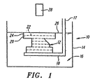
- FIG. 1 generally depicts a stereolithographic apparatus ("SLA") 10 in which object 12 is formed, and is set forth to familiarize the reader with terms used herein.
- SLA 10 may include a vat 14 which contains a volume of the building material 16 used to form object 12.
- Object 12 may be built on platform 18 which may be vertically movable and coupled to support arms 17 that may be coupled to a computer-controlled elevator (not shown).
- Object 12 is formed of successive cross-sections which are shown by the dashed lines.
- the last-formed object cross-section 20 has a top surface 22 on which the next layer of building material 24 is formed.
- building material layer 24 may be formed in several ways.
- Platform 18 may be lowered while maintaining the surface of the volume of material 16, i.e., working surface 26, at a fixed level.
- working surface 26 typically refers to the surface of the volume of building material 16 in vat 14.
- working surface 26 is at a desired level or plane, and is thus a "desired working surface” that is located at a specified distance from the source 28 of synergistic stimulation during exposure to synergistic stimulation.
- the actual working surface and desired working surface are both denoted with reference numeral 26 but where the actual and desired working surfaces may deviate from each other, the disclosure explains such deviation.
- platform 18 and thus top surface 22 may remain stationary at a fixed level, and the volume of material 16 in vat 14 may be increased thereby raising working surface 26. This may occur by pumping more material into vat 14 from below working surface 26, or by dispensing more material into vat 14 from above working surface 26. A combination of the foregoing approaches is also possible.
- building material layer 24 of Figure 1 may be formed by "deep-dipping" platform 18. That is, platform 18 and thus surface 22 may be lowered more than the intended thickness of the next object cross-section below working surface 26 so that material 16 flows over surface 22 more easily. Platform 18 is then raised so that the thickness of layer 24 approximates the desired thickness. Alternatively, working surface 26 may be raised in excess and then lowered. Deep-dipping is used because if platform 18 is lowered or working surface 26 raised an amount equal to only one layer thickness, material 16 may not flow, or at least not flow in a reasonable time period, over surface 22 due to viscosity and surface tension effects. Instead, material 16 will typically form a boundary around the periphery of surface 22 (see boundary 68 in Figure 5a).
- boundary 68 may remain stationary or alternatively may move slowly inward toward the center of the previous cross-section. Deep-dipping is discussed in detail in previously incorporated U.S. Patent No. 4,575,330 and 5,174,931.
- Working surface 26 may be raised relative to top surface 22 by other techniques which also help serve to form a building material layer 24.
- the thickness of the building material layer 24 may substantially approximate the desired thickness of the next object cross-section or may vary from the desired thickness.
- One reason that the thickness of layer 24 may be varied from the thickness of the next object cross-section is to compensate for errors that may have arisen in connection with forming previous object cross-sections, or to compensate for anticipated errors.
- building material layer 24 may be formed thicker than the intended object cross-section to compensate for the thickness that will be lost to shrinkage. Also, to ensure that the actual working surface 26 remains a proper distance from the source of synergistic stimulation 28 so that is therefore a desired working surface 26, and to rectify thickness errors that may have accumulated over successive layers, independent liquid leveling may occur in association with the recoating process for each layer or for periodic layers. Depending on the timing, amount and direction of level correction, a building material layer thickness may be somewhat greater or less than the desired thickness of the next object cross-section. Lastly, due to possible inaccuracies in the building material layer used to form the last formed object cross-section 20, or due to possible distortions in the last object cross-section 20 arising from shrinkage or curl, the current building material layer thickness may vary from the desired thickness.
- the thickness of layer 24 may be varied from the thickness of the next object cross-section, at least initially, is because building material layer 24 may be formed in several steps, i.e., it is initially formed at a certain thickness and then adjusted to a desired thickness. For example, when deep-dipping occurs, building material layer 24 may initially be thicker than desired because excess material 16 may remain over surface 22 after platform 18 is brought back up. This thicker-than-intended initial building material layer 24 may then be adjusted to the desired thickness by a doctor blade or other device as described below. Where a doctor blade or other smoothing device is used to form a building material layer 24, the thickness of layer 24 may end up being less than desired because the doctor blade may have swept away too much material 16. Alternatively, the thickness may be greater than desired because the doctor blade may not have swept away sufficient material. This results in the actual working surface not coinciding with the desired working surface.
- the initial building material layer 24 may be adjusted to the desired thickness by raising or lowering working surface 26 relative to top surface 22 an additional increment to compensate.
- a building material layer 24 of desired thickness After a building material layer 24 of desired thickness is formed, it is exposed to synergistic stimulation from a source of synergistic stimulation 28. This causes building material layer 24 to solidify or otherwise physically transform thereby forming the next object cross-section. Successive building material layers 24 and object cross-sections 20 are then aternatingly formed to complete the object 12.
- applicator 310 simultaneously applies and smoothes a building material layer 24.
- object 12 is dipped one layer thickness, or other desired thickness, below the desired working surface 26 of building material 16.
- applicator 310 is at least partially filled with material 16 and after the exposure process, applicator 310 is swept at or slightly above the desired working surface 26 while dispensing material from opening 315 to form building material layer 24.
- the vertical position of the upper surface 22 of the last formed object cross-section 20 may be adjusted if necessary so that it is essentially one layer or other desired thickness below the desired working surface 26.
- Applicator 310 may be coupled to the SLA by a frame and drive system (not shown) so that it may be swept horizontally at or slightly above working surface 26. Applicator 310 is preferably computer controlled for precise formation of building material layer 24. It is preferred that applicator 310 be swept only as far as needed (as opposed to sweeping applicator 310 across the entire vat 14) to ensure formation of an adequate building material layer 24 and to ensure a free path for exposure to synergistic stimulation from source 28.
- the resin volume in applicator 310 is maintained by vacuum pump 321, pressure regulator 323, and vacuum feed line 325.
- the application of vacuum through line 325 into the upper portion of cavity 327 of applicator 310 causes a pressure differential to occur between the inside of cavity 327 and the region outside applicator 310.
- Applicator 310 is sealed with the exception of one or more openings near its top and with the further exception of opening 315 at its bottom. The openings near the top of applicator 310 provide for connection to vacuum feed line 325, while the opening at the bottom forms a slit for applicator 310 to receive and dispense building material 16.
- This controlled amount of material 16 is specified to be at least as great as the maximum amount of material 16 necessary to form the next layer 24. Assuming that layer 24 will be formed over the entire area of vat 14, the volume of this maximum amount of material 16 is equal to the thickness of the layer 24 to be formed multiplied by the cross-sectional area of vat 14 holding building material 16. However, it is preferred that the controlled amount of material 16 contained by applicator 310 be significantly greater than the anticipated maximum amount to form layer 24. The resulting excess ensures that applicator 310 will not run dry during a sweep and thereby ensures that meniscus 331 will not be broken.
- the length 322 of applicator 310 as shown in Figure 2c is slightly less than the inside width of vat 14 or at least slightly extends beyond the maximum extent of object 12.
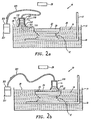
- Figure 2a depicts applicator 310 to the left of object 12 shortly after object 12 has been dipped one layer thickness below working surface 26 by elevator 17 which is coupled to platform 18.
- material 16 is drawn to a significant height in cavity 327.
- Figure 2b depicts applicator 310 after it has been swept almost the full distance across the last formed object cross-section 20.
- the height of the resin column in cavity 327 has decreased due to the volume of material 16 dispensed during sweeping.
- vat 14 Since the sum of the volume of material in applicator 310 and vat 14 is essentially a constant amount (ignoring shrinkage of cured material and volume changes due to aperture fluctuations), if the amount of material in applicator 310 varies, so will the amount and associated surface level of material in vat 14.
- Applicator 310 includes flanges 312 which in turn include angled portions as shown in Figures 2a-2b that help reduce any leading edge bulge problems.
- Figure 2c depicts a perspective view of the preferred applicator 310.
- applicator 310 may comprise an elongated bar with a hollow interior.
- Figure 2c also depicts several holes 326 along the top of applicator 310 which represent locations at which one or more vacuum feed lines 325 may be connected. Preferably, care is taken to ensure a tight fit between lines 325 and holes 326 to prevent undue loss of vacuum pressure.
- Figure 2c also depicts viewing port 335 which is formed by making a hole in applicator 310 and installing a window thereover to preserve the vacuum. From viewing port 335, the height of building material 16 in applicator 310 may be visually determined.
- Figures 2d-2f depict the preferred applicator 310 of Figures 2a-2c from end, side and bottom views. Each of these views depicts dimensions of an applicator of the type described herein as implemented on an SLA-250 stereolithographic apparatus as sold by 3D Systems, Inc. of Valencia, Calif. Holes 337 depict mounting holes for attaching applicator 310 to the existing doctor blade mount on 3D Systems' SLA 250 stereolithography apparatus.
- the presently preferred vacuum pump for use with the applicator of Figures 2d-2f is Model No. 3020 sold by Apollo pumps of Ontario, Calif.
- the vacuum regulator supply a stable vacuum pressure sufficient to pull material 16 about 1/2" (1.27 cm) up into applicator 310.
- the volume of material 16 typically drawn up into it is approximately 20 to 25 mL, whereas the volume of material in a single 0.15 mm layer produced by an SLA 250 is approximately 9 to 12 mL.
- a preferred pressure regulator involves the use of a bleeder valve that may be adjusted to allow a small but continuous supply of air to bleed into applicator 310 thereby providing an equilibrium vacuum pressure that is sufficient to pull material into the applicator 310 the desired amount.
- Figure 2g depicts a side view of applicator 310 spaced above working surface 26 by a small amount.
- This spacing between the bottom of applicator 310 and desired working surface 26 during sweeping is analogous to the "blade gap" associated with the use of doctor blades and is herein referred to as the "applicator gap” (AG).
- appliance gap an appliance gap
- stereolithography resin SL 5170 is most preferred but it is believed that other stereolithography resins offered by 3D Systems, Inc. can be used as well.
- Successful layer-forming experiments have been performed with applicator gaps varying from 3 to 10 mils (0.075 to 0.25 mm). Though the lower limit on applicator gap AG is zero, this has been found to be generally less than optimal due to leading edge bulge problems and increased potential for collisions between applicator 310 and object 12 being formed.
- the upper limit on applicator gap AG is the maximum height above working surface 26 at which a reliable meniscus 331 may be maintained between applicator 310 and working surface 26.
- This maximum applicator gap AG is typically somewhere below 30 to 35 mils (0.75 to 0.88 mm) but is dependent on the building material 16 used.
- the optimal value of applicator gap AG is the smallest gap at which collisions between applicator 310 and object 12 are essentially non-existent and leading edge bulge is not a problem. It is believed that this optimal value is dependent on the properties of the material 16 being used such as viscosity, as well as the configuration of applicator 310.
- the present most preferred values of applicator gap are between 5 and 8 mils (0.125 to 0.2 mm), inclusive.
- Figure 2h depicts the spacing between the bottom of applicator 310 and the upper surface 22 of the last formed object cross-section 20 during sweeping.
- This spacing is known as the "applicator clearance” AC and is analogous to the "blade clearance" associated with the use of a doctor blade.
- Typical applicator clearances AC range from about one (1) layer thickness to about three (3) layer thicknesses.
- the presently most preferred range of applicator clearances AC is between 1.1 and 1.7 layer thicknesses and the most preferred value is currently about 1.4 layer thicknesses.
- the upper surface of the last formed object layer may be located at a position above or below its desired position for exposing a layer of material to form a next cross-section of the object.
- the object may need to be raised or lowered slightly after sweeping with applicator 310 to complete the coating process so that a next object cross-section can be formed.
- the foregoing recoating embodiment exerts lower forces on object 12 during the recoating process which advantageously results in an overall reduction in object 12 distortion.
- This reduction in force exerted on object 12 also provides that previously formed cross-sections such as last-formed object cross-section 20 require less structural modulus to retain their integrity.
- the resulting reduction in need for immediate green part structural modulus leads to broader process latitude in deriving build parameters and also eases development efforts necessary in finding suitable object building materials, e.g., epoxy resins, by easing acceptance criteria.
- the building material layers 24 formed by this preferred embodiment provide self-correction of minor errors in thickness from layer-to-layer, e.g., due to shrinkage or simply due to coating errors, which reduces or eliminates the need for a periodic accumulated error checking and/or correction. In any event such a periodic process may still be used if desired, e.g., deep dip and sweep off every Nth layer.
- this preferred applicator 310 embodiment performs two functions at the same time: (1) it applies material 16 to initially form building material layer 24a and (2) simultaneously smoothes layer 24a to form a final building material layer 24 having a working surface essentially coplanar with the desired working surface 26.
- This preferred applicator embodiment also: (1) forms more accurate layers of material, (2) significantly reduces recoating time and (3) allows the use of generalized, i.e. readily automatable, recoating parameters. It is further anticipated that further reductions in build time may be achieved by exposing the first-dispensed portion of layer 24 to synergistic stimulation to form a next object cross-section while applicator 310 is still dispensing the latter-dispensed portion of layer 24 over the last-formed object cross-section 20.
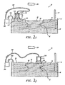
- Figures 2i and 2j depict a second preferred embodiment of applicator 310.
- cavity 327 of applicator 310 is not filled with building material 16 via vacuum pump 321, regulator 323 and vacuum tube 325. Instead, material 16 is maintained in cavity 327 via pump 340, extraction tube 342 and fill tube 344.
- material 16 is drawn to pump 340 from applicator 310 by suction through extraction tube 342 and dispensed from pump 340 through tube 344 back into vat 14.
- the arrows in the figures indicate the direction of material flow in the tubes.
- the entry location of fill tube 344 into building material 16 may be surrounded by a fence, wall or bubble catcher (not shown).
- the presently preferred pump 340 is a diaphragm or piston pump, Model No. 50000-072, sold by Cole Parmer. This pump has a controllable flow rate up to a maximum flow of 0.3 gallons per hour. In a given application, the required flow rate may be greater than the amount of material comprising the number of layers to be formed in a given time period. However, it is preferred that the flow rate be significantly larger than this amount to preserve the integrity of meniscus 331. To further preserve meniscus 331, it is preferred to let pump 340 run continuously so as to constantly pull material 16 through applicator 310 and redeposit it into vat 14 regardless whether or not applicator 310 is sweeping.
- a peristaltic pump may be more preferred in the long term to minimize cleaning time and problems when the building material to be used in the SLA is changed.
- the SLA may include separate pumps and tubing for each building material to be used. Separate applicators 310 may also be used for each building material.
- a quantity of material 16 sufficient to form building material layer 24 may be pumped to applicator 310 during exposure of the last formed object cross-section 20.
- material 16 may be pumped to applicator 310 as it forms building material layer 24.
- Figure 2k depicts an alternate embodiment applicator 310 which includes a bleeder valve 350 that is preferably electrically actuated, e.g., by a solenoid and computer controlled to open and close as commanded.
- applicator 310 may be loaded with material 16 by lowering applicator 310 in the downward direction of arrow 352 partially into building material 16 while at the same time opening bleeder valve 350.
- bleeder valve 150 may be closed and applicator 310 may be raised vertically in the upward direction of arrow 352, out of material 16 so that its lower surface is located above the desired working surface 26 by the desired applicator gap AG.
- applicator 310 Since applicator 310 maintains contact with the body of building material 16 in vat 14 via meniscus 331, and since applicator 310 is completely sealed due to the closure of valve 350, material 16 remains trapped in applicator 310. After loading applicator 310, it may be swept horizontally above the previously formed object cross-section 20, as depicted by arrow 354, to form a next building material layer 24.
- the direction of material pumping may be reversed. So long as the bottom of slotted applicator 310 is located within the meniscus connecting the applicator and the working surface, it is believed acceptable coatings will be formed so long as the material dispensing rate is matched to the sweeping speed to yield a coating of desired thickness over the last formed object cross-section 20 and over any other shallow regions. Applicator 310 may still continue to withdraw and dispense material away from the shallow regions when not sweeping.
- Figure 21 depicts an alternative embodiment of applicator 310.
- applicator 310 may comprise several components which may move relative to one another including: upper element 311, flanges 312 and end caps 313 (the end cap at the far end of applicator 310 is not shown). As with the previous embodiments, these components form a sealed applicator 310.
- applicator 310 is filled with material 16 by (1) reducing the volume of cavity 327 before or while applicator 310 is in contact with material 16 and then (2) expanding the volume of cavity 327 while the bottom of applicator 310 is in contact with building material 16.
- the contraction and expansion of cavity 327 may be accomplished by moving flanges 312 closer and further away as flanges 312 slide along upper element 311 and end caps 313.
- the expansion and contraction of flanges 312 is preferably performed under computer control utilizing solenoids, electric motors with ball screws, pneumatic pressure or the like. Since during the expansion applicator 310 is sealed by tight fits between its components, the only way to balance the growing vacuum in cavity 327 is to draw material 16 into applicator 310. Once sufficient material 16 is drawn into applicator 310, expansion may stop and sweeping and associated material deposition may begin.
- Figure 2m depicts an end view of an alternative applicator 310 which may also contract and expand.
- contraction and expansion of cavity 327 may be accomplished by moving upper element 314 down before or while applicator 310 contacts material 16, and up after applicator 310 is in contact with material 16 thereby creating a vacuum and filling cavity 327.
- upper element 311 may again be moved downward thereby creating a force on material 16 to facilitate dispensing.
- a sponge of other wicking material may be inserted in the applicators 310 of Figures 2a, 2i, 2l and 2m. Referring to Figure 2k this sponge may also be used to wick material up into applicator 310 while valve 350 is open thereby eliminating the need to lower applicator 310 into building material 16 in order to fill cavity 327.
- the sponge may be utilized in the embodiments of Figures 21-2m wherein the drawing of material 16 into the sponge occurs by expanding cavity 327 as described above. Dispensing from an applicator 310 including the sponge may occur while sweeping with applicator 310 sealed. Alternatively, sweeping may occur with valve 350 open, with end caps 313 removed or with cavity 327 being contracted.
- the wicking or capillary capabilities of the sponge eliminates the need for sweeping with a sealed applicator. Different wicking materials may be useful for different building materials so that the wicking rate and ability to dispense are optimized.
- the sponge be positioned within applicator 310 so that the bottom of the sponge is slightly above the bottom of flanges 312.
- the wicking element includes a number of closely spaced inner flanges 364 that are positioned within flanges 312 and upper element 311 and that are sized appropriately to allow capillary forces to draw material up into applicator 310.
- the distance 362 between inner flanges 364 may vary with material viscosity but where material 16 comprises a photopolymerizable resin such as SL 5170, a gap 362 of 0.05 to 0.150 inches (1.3 to 3.8 mm) is preferred.
- inner flanges 364 may be coated with a porous material to enhance the capillary action of flanges 364.
- Inner flanges 364 may also be moved vertically so they can be filled by immersion into building material 16 in vat 14. Alternatively material 16 may be fed between inner flanges 364 by pumping.
- roller 370 may comprise a cylinder which is coupled to applicator 310 at its ends by axle 372. Roller 370 is preferably driven so that it rotates with a tangential speed matching the translational speed of the applicator 310 thereby eliminating any horizontal motion of the bottom of roller 370 relative to working surface 26. Alternatively roller 370 may spin freely so that it may rotate as applicator 310 translates along working surface 26. Roller 370 is preferably made of aluminum but may alternatively comprise a sponge-like material or may have a sponge-like coating or surface. As a further alternative, roller 370 may have a knurled or other machined surface which provides more surface area to receive material 16.
- the bottom of roller 370 may be located at or above the bottom of flanges 312 and is preferably located in the range of about 0.002 and 0.200 inches above the bottom of flanges 312.
- material 16 within cavity 327 need not touch the inner walls of applicator 310 but may simply cling to roller 370 and rotate with it.
- material 16 may uniformly fill cavity 327 up to a desired height.
- roller 370 may be rotated while in contact with material 16 so as to build up a rotating mass of material 16 thereon.
- FIG. 2p An alternate applicator embodiment is shown in Figure 2p which includes vacuum/feeder line 380 and priming device 382. This embodiment may also be used with the other types of applicators 310 discussed above.
- Line 380 extends from within vat 14, is coupled to priming device 382 and enters applicator 310 through upper element 311.
- Line 382 may alternatively enter applicator 310 through a flange 312.
- line 380 may extend from a separate reservoir (not shown) containing material 16.
- the embodiment of Figure 2p operates on vacuum pressure, which vacuum may be initially created by priming device 382 that may include valve 384, reservoir 386 and vacuum pump 388.
- priming device 382 may include valve 384, reservoir 386 and vacuum pump 388.
- vacuum pump 388 may be activated with valves 384 and 387 open and 385 closed.
- Valve 383 which may bleed air into the vacuum system may be opened or closed, preferably closed. This serves to draw material 16 from vat 14 through line 380, through valve 384 and into reservoir 386.
- This priming process may occur until material 16 fills some portion of reservoir 386 so that the material level is generally above valve 384.
- valve 387 is closed
- valve 385 is opened
- valve 388 is closed and/or valve 383 is opened or opened further.
- valves 383 and 388 will maintain material in the applicator at a desired level.
- valve 384 may be closed and valves 385 and 387 opened during sweeping.
- material 16 leaves applicator 310, more material 16 is drawn from vat 14 through line 380 and into applicator 310 because of the existing vacuum and siphoning principles.
- applicator 310 is supplied with material 16 for as long as necessary to form building material layer 24.
- trailing edge flange 312 is preferably positioned at the desired height above surface 22 to ensure that layer 24 is of desired thickness.
- applicator 310 be swept in alternating directions during successive sweeps across vat 14
- applicator 30 may always be swept in the same direction during the recoating process.
- Applicator may also make multiple passes over the last-formed object cross-section 20 in the process of forming a next building material layer 24.
- the configuration of applicator 310 may not be strictly symmetrical.
- applicator 30 may have a different configuration than that described in the foregoing embodiments.
- applicator 310 or some portion thereof, e.g., flange 312 or a portion of flange 312 near working surface 26, may be made of a flexible material such as rubber or a brush.
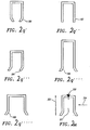
- Figures 2q-2q""' depict several examples of other possible applicator configurations.
- Element 190 in Figure 2q depicts an applicator with the flanges curving inward near the working surface.
- Element 192 in Figure 2q" depicts the applicator having vertical flanges.
- Element 194 in Figure 2q"' depicts a non-symmetrical applicator. If the flanges of element 194 are rigid, the depicted applicator would be most applicable for use wherein a single sweeping direction is utilized during recoating, where an even number of sweeps will be performed, or where multiple applicator bars will be simultaneously used.
- the applicator may be useful when sweeping in either direction since it would be expected that the flanges would take opposite positions when being swept in opposite directions.
- Elements 196 of Figure 2q"" and element 198 of Figure 2q""' depict two larger applicators so that larger volumes of material can be pulled into the applicator, so that larger layers may be used, so that higher viscosity materials may be readily used, or so that faster sweep speeds may be used. Multiple applicators may also be used.
- applicator 310 has a length 322 which extends across a significant portion of vat 14 so that building material layer 24 may be formed in a single sweep.
- multiple applicators 310 may be used with shorter lengths 322 to pass over different portions of vat 14.
- applicator 310 may have a short length and may be swept over different portions of working surface 26 on successive sweeps.
- applicator 310 and the frame (not shown) coupling applicator 310 to the SLA preferably comprise a lightweight material such as aluminum.
- the resulting lightweight reduces the amount of force necessary for accelerating and decelerating during transportation.
- working surface 26 should be located at a desired level relative to the source 28 of synergistic stimulation, which desired level is typically considered to be an ideal plane. Furthermore, this desired level is typically a fixed level which is maintained by independent liquid level control means such as those discussed in U.S. Patent No. 4,575,330.
- the most preferred independent liquid level control system includes a level detection means and a vat hoist means for effectively raising-lowering the liquid levels.
- applicator 310 draws material 16 from vat 14 and redispenses material back into vat 14 when forming layer 24, and if it desired that an ideal plane of material 16 be formed and then exposed to form a next object cross-section, care is preferably taken to ensure that applicator 310 contains a substantially constant volume of material 16 during exposure of each layer. If applicator 310 holds only a small volume of material 16 and is being filled so as to increase the volume of material 16 contained therein during the exposure process, it may be possible to neglect the decrease in surface level in portions of the vat, i.e., regions of deep liquid.
- applicator 310 holds a large volume of material 16 one preferably avoids changing the volume of material 16 being held in applicator 310 during exposure, lest working surface 26 be excessively varied and inaccuracies in formation of object cross-sections result or worse, delaminations between layers occur.
- the amount of tolerable variation in the level of working surface 26 depends on a number of factors including: (1) overall object 12 accuracy desired, (2) method of exposing layer 24, (3) direction of variation in surface level, (4) exposure levels used in forming layers and (5) geometry of the object 12 being formed. Depending on the liquid leveling scheme used, one may also need to consider any layer-to-layer variations in the amount of material 16 being held in applicator 310 even if the amount is held constant during formation of individual objects cross-sections.
- balancing attempts of the third and fourth approaches may involve an interaction between displaced amounts or alternatively the amounts being displaced may merely be estimated to match.
- a rapid transfer of material 16 may be made between the separate chamber and vat 14 via a connecting line in order to account for material 16 transferred via applicator 310 between the separate chambers.
- the separate chamber may be connected to vat 14 by only a shallow surface region of material 16 and wherein applicator 310 may be swept from vat 14 to the separate chamber.
- applicator 310 may be swept from the separate chamber to vat 14 and vice-a-versa. Also, since this surface region is shallow, level changes in vat 14 and separate chamber(s) may occur almost independently due to the long flow time necessary to transfer material 16 through the shallow region.
- slotted and sealed applicators may involve use of multiple sweeps, varying sweep speeds between successive sweeps, varying applicator clearances between sweeps, delays after sweeping, multiple short applicators, applicators with multiple slots forming parallel lines or sitting end to end, and the like. Further embodiments may also be derived by combining the teachings herein regarding slotted and sealed applicator embodiments with each other, or with the teachings regarding the other recoating techniques described above and below.
- synergistic stimulation is applied after completion of sweeping. If multiple sweeps are used to form layer 24, exposure may begin during a final sweep. A delay may also be set between the completion of sweeping and beginning of exposure to allow minor surface imperfections to settle. Alternatively, where multiple sweeps are used to form layer 24, exposure may begin prior to completion of the first sweep.
- the various parameters discussed above may be manually adjusted or preferably computer controlled during the building of object 12. These types of adjustments might be useful when layer thickness is varied during object building, when temperature changes occur during object building, or when building materials are switched so that manual operator intervention is not necessary.
- shallow regions Only regions that are deep and connected by large flow paths will readily achieve a uniform level.
- the depth of a region for it to be considered shallow arid possibly troublesome depends on the viscosity and surface energy of the building material and on the surface energy of transformed building material.
- shallow regions generally have depths of less than about 40 mils (1 mm) to about 240 mils (6 mm). For materials with relatively low viscosities, e.g., 1 to 100 centipoise, it is estimated that the shallow regions will include regions having a depth of no more than 40 mils or less.
- the shallow regions will include regions shallower than about 40 to 120 mils (1 to 3 mm).
- the shallow regions may include regions having depths of up to 120 to 240 mils (3 to 6 mm) or more.
- layer or cross-sectional comparisons may be performed on the data descriptive of the cross-sections of object 12 to determine exactly what regions for each layer should be considered shallow regions.
- Layer comparison techniques are disclosed in U.S. Patent No. 5,481,470.
- the material in regions that are isolated from or poorly connected to the bulk of material 16 in vat 14, may also be determined. These type of regions include trapped volumes and regions that are "near" trapped volumes. There are various methods for ensuring that trapped volume regions and near trapped volume regions are included with shallow regions in defining the area to be coated by ink jet printhead 100. The most straightforward approach is to perform a Boolean union of all regions included on any previous cross-section of the object, connected objects and supports. The result of this Boolean union defines the region to be coated in forming building material layer 24.
- a simple modification to this calculation involves including a switch which may be set by the SLA operator for indicating whether or not object 12 contains trapped volumes and/or near trapped volumes. Based on the setting of this switch, determination of which trapped areas are to be coated for each layer will be derived from either the N previously formed object cross-sections or all previously formed object cross-sections. Depending on the configuration of the object, having the switch set to a "no trapped volumes" setting will result in coating of an amount of material less than or equal to that which would otherwise be coated if the switch were oppositely set.
- each object cross-section may be used to determine a rectangular minimum dispensing region.
- the Boolean union of the minimum rectangular dispensing region from each of the immediately preceding N cross-sections may be formed. This Boolean union represents the net dispensing region.
- a fully automated technique may also be implemented to derive a minimum area to be coated when forming each layer.
- the depths to be associated with shallow regions may be determined by experimentation.
- One may perform recoating tests over a cross-section with a relatively large cross-sectional area and critical circle.
- the cross-sectional area and critical circle of the cross-section should be selected to correspond to the cross-sectional dimensions of the objects which will be typically built on the SLA. For example, if one intends to build primarily small objects, e.g., objects having cross-sections with critical circles with radii less than 1/2 inch (1.27 cm), then a test surface with a critical circle of radius 1/2 inch (1.27 cm) may be used.
- test surface of similar size should be used. One may then dip the surface into the liquid varying depths and determine the time required for material to flow over the cross-section for the different depths.
- the minimum depth for which a coating is formed in a reasonably small period of time, e.g. less than 2 to 5 seconds, may define the depth of the shallow regions.
- inverse erosion routines i.e., expansion routines
- expansion routines it is possible to perform one or more inverse erosion routines, i.e., expansion routines, on regions which are determined to require ink jet dispensing in order to expand these regions some specified amount to ensure adequate coating by the ink jet print heads 100. This is especially so when it is desired to avoid precise registration between ink jet dispensing locations when forming layers and exposure locations when forming cross-sections.
- Erosion routines and inverse erosion routines are described in U.S. Patent Nos. 5,481,470 and 5,597,520.
- inverse erosion routines are similar to line width, cure width, or beam width compensation techniques except that the compensation amount is negative which results in an expansion of the cross-sectional area as opposed to the a contraction of the region.
- ink jet control is preferably based on bit map representations of the regions to be coated.
Landscapes
- Engineering & Computer Science (AREA)
- Chemical & Material Sciences (AREA)
- Materials Engineering (AREA)
- Mechanical Engineering (AREA)
- Manufacturing & Machinery (AREA)
- Physics & Mathematics (AREA)
- Optics & Photonics (AREA)
- Conveying And Assembling Of Building Elements In Situ (AREA)
- Heating, Cooling, Or Curing Plastics Or The Like In General (AREA)
- Materials For Medical Uses (AREA)
- Coating Apparatus (AREA)
Claims (52)
- Gerät zum Bilden von zumindest einem Teil eines dreidimensionalen Gegenstandes auf einer im Wesentlichen querschnittsmäßigen Basis aus einem Material, das geeignet ist für eine physikalische Transformation auf ein Exponieren gegen eine synergistische Stimulation hin, aufweisend:Mittel zum Liefern von Daten, die für den Gegenstand beschreibend sind;einen Behälter (14) zum Enthalten eines Volumens von Material (16) mit einer Arbeitsoberfläche (26);einen Applikator (310) zum Bilden von Schichten von Material über zumindest Teilen eines zuvor gebildeten Gegenstandsquerschnitts, wobei der Applikator (310) eine Bodenöffnung (315) aufweist, die sich in der Nähe der Arbeitsoberfläche (26) befindet;eine Vorrichtung (321, 340), die mit dem Applikator (310) gekoppelt ist zum Ziehen von Material (16) von der Arbeitsoberfläche (26) in den Applikator (310), der einen Gießspiegel (331) zwischen dem Applikator (310) und der Arbeitsoberfläche (26) bildend;Mittel zum Ablenken des Applikators (310) über zumindest einen Teil von zumindest einigen der zuvor gebildeten Gegenstandsquerschnitte; undeine Quelle einer synergistischen Stimulation (28) zum Exponieren der Schicht gemäß den beschreibenden Daten, um den zumindest einen Teil des Gegenstandes aus einer Mehrzahl von Gegenstandsquerschnitten zu bilden.
- Gerät nach Anspruch 1, wobei die Vorrichtung (321) das Material von der Arbeitsoberfläche durch die Bodenöffnung (315) des Applikators (310) hinaufzieht.
- Gerät nach Anspruch 1 oder Anspruch 2, wobei die Vorrichtung (321), die mit dem Applikator (310) gekoppelt ist, eine Vakuumpumpe aufweist.
- Gerät nach Anspruch 3, das des Weiteren einen Druckregler (323) aufweist zum Steuern des Druckdifferentials zwischen der Innenseite und Außenseite des Applikators (310), um die Materialmenge, die in den Applikator (310) gezogen wird, zu steuern.
- Gerät nach Anspruch 1 oder Anspruch 2, wobei die Vorrichtung, die mit dem Applikator (310) gekoppelt ist, eine Fluidpumpe aufweist.
- Gerät nach Anspruch 5, wobei die Fluidpumpe (340) Material durch den Applikator (310) zieht und Material zu dem Behälter (14) zurückführt, und wobei ein Mittel vorgesehen ist an oder um die Position, wo das Material in den Container wiedereingeführt wird, um die Bildung von Blasen zu verhindern.
- Gerät nach Anspruch 1 oder Anspruch 2, wobei ein Docht vorgesehen ist, um Material von der Arbeitsoberfläche (26) in den Applikator (310) zu ziehen.
- Gerät nach Anspruch 7, wobei das Dochtmittel eine Zahl von nahe beabstandeten Flanschen aufweist, die angeordnet sind um zu ermöglichen, dass Kapillarkräfte Material in den Applikator (310) ziehen.
- Gerät nach Anspruch 1 oder Anspruch 2, das des Weiteren ein Mittel zum Reduzieren und Ausdehnen des inneren Volumens (327) des Applikators (310) aufweist.
- Gerät nach Anspruch 1 oder Anspruch 2, das des Weiteren ein Entnahmeventil (350) aufweist, das so angeordnet ist, dass das Entnahmeventil (350) geöffnet wird, wobei ermöglicht wird, dass Material in den Applikator (310) gezogen wird, und dass es geschlossen wird, um Material in dem Applikator (310) zu halten.
- Gerät nach irgend einem der vorhergehenden Ansprüche, wobei der Applikator (310) so angeordnet ist, dass die Materialmenge in dem Applikator (310), bevor er über zumindest einen Teil der Arbeitsoberfläche (26) abgelenkt wird, zumindest so viel ist, wie erforderlich ist, um die nachfolgende Schicht zu bilden.
- Gerät nach irgend einem der vorhergehenden Ansprüche, wobei der Applikator (310) Flansche beinhaltet, um eine Ausbauchung an der Vorderseite des Materials (16) zu reduzieren, wenn der Applikator (310) über zumindest einen Teil der Arbeitsoberfläche (26) abgelenkt wird.
- Gerät nach irgend einem der vorhergehenden Ansprüche, wobei der Applikator (310) eine Rolle (370) beinhaltet, die innerhalb des Applikators (310) vorgesehen ist.
- Applikator nach Anspruch 13, der des Weiteren ein Mittel aufweist, um die Rolle (370) mit einer Geschwindigkeit zu drehen, so dass es dort keine relative horizontale Bewegung zwischen der Rolle (370) und der Arbeitsoberfläche (26) gibt, wenn der Applikator (310) über zumindest einen Teil der Arbeitsoberfläche (26) abgelenkt wird.
- Applikator nach irgend einem der vorhergehenden Ansprüche, wobei der Applikator (310) ein transparentes Fenster (335) aufweist, durch welches das Vorhandensein von Material (16) im Applikator (310) beobachtet werden kann.
- Gerät nach irgend einem der vorhergehenden Ansprüche, das des Weiteren ein Mittel aufweist, das angeordnet ist, um den Applikator (310) über den zumindest einen Teil der Arbeitsoberfläche (26) in entgegengesetzten Richtungen für die Bildung von aufeinander folgenden Schichten abzulenken.
- Gerät nach irgend einem der vorhergehenden Ansprüche, das des Weiteren ein Mittel aufweist, das angeordnet ist, um den Applikator (310) mehrere Male über den zumindest einen Teil der Arbeitsoberfläche 26 für die Bildung einer Schicht abzulenken.
- Gerät nach irgend einem der vorhergehenden Ansprüche, wobei eine Mehrzahl von Applikatoren (310) vorgesehen ist.
- Gerät nach Anspruch 18, wobei die Mehrzahl von Applikatoren (310) Ende an Ende angeordnet sind, im Allgemeinen quer zu der Ablenkrichtung.
- Gerät nach Anspruch 18, wobei die Mehrzahl von Applikatoren (310) Seite an Seite angeordnet sind, im Allgemeinen parallel zueinander.
- Gerät nach irgend einem der vorhergehenden Ansprüche, das des Weiteren ein Mittel aufweist, um die Ablenkgeschwindigkeit des Applikators (310) zwischen aufeinander folgenden Ablenkungen zu variieren.
- Gerät nach irgend einem der vorhergehenden Ansprüche, das des Weiteren ein Mittel aufweist, um den Abstand zwischen dem Applikator (310) und der Arbeitsoberfläche (26) zwischen aufeinander folgenden Ablenkungen zu variieren.
- Gerät nach irgend einem der vorhergehenden Ansprüche, das des Weiteren ein Mittel aufweist zum Verzögern des Exponierens einer Schicht für ein vorbestimmte Periode, nachdem der Applikator (310) über den zumindest einen Teil der Schicht abgelenkt worden ist.
- Gerät nach irgend einem der vorhergehenden Ansprüche 1 bis 23, das des Weiteren ein Mittel aufweist, das angeordnet ist, um einen Teil einer abgeschiedenen Schicht von Material einer synergistischen Stimulation auszusetzen, wenn ein nachfolgender Teil der Schicht durch den Applikator (310) abgeschieden wird.
- Gerät nach irgend einem der vorhergehenden Ansprüche, das des Weiteren ein Mittel aufweist zum automatischen Bestimmen von zumindest einem Parameter zum erneuten Beschichten.
- Gerät nach irgend einem der vorhergehenden Ansprüche, wobei der Applikator (310) mehrere Schlitze beinhaltet.
- Gerät nach irgend einem der vorhergehenden Ansprüche, das des Weiteren ein Mittel aufweist, das angeordnet ist, um den Applikator (310) nur über einen Teil der Arbeitsoberfläche (26) abzulenken.
- Verfahren zum Bilden von zumindest einem Teil eines dreidimensionalen Gegenstandes auf einer im Wesentlichen querschnittsmäßigen Basis aus einem Material, das geeignet ist für eine physikalische Transformation auf ein Exponieren gegen eine synergistische Stimulation hin, aufweisend:Zuführen von Daten, die für den Gegenstand beschreibend sind;Beinhalten eines Volumens eines Materials (16), das eine Arbeitsoberfläche (26) aufweist;Platzieren eines Applikators (310), der eine Bodenöffnung (315) aufweist in der Nähe der Arbeitsoberfläche (26);Bilden eines Gießspiegels (331) von Material (16) zwischen dem Applikator (310) und der Arbeitsoberfläche (26);Ziehen von Material (16) von der Arbeitsoberfläche (26) in den Applikator (310), wodurch zumindest teilweise der Applikator (310) gefüllt wird;Bilden einer Schicht über zumindest einem Teil eines zuvor gebildeten Gegenstandsquerschnitts, einschließlich eines Ausgebens von Material (16) von dem Applikator (310) durch Ablenken des Applikators (310) über zumindest einen Teil des zuvor gebildeten Gegenstandsquerschnitts;Exponieren ausgewählter Teile der Schicht gagen eine synergistische Stimulation entsprechend den beschreibenden Daten, um einen Gegenstandsquerschnitt zu bilden, der an dem zuvor gebildeten Gegenstandsquerschnitt haftet; undWiederholen des Bildens und Exponierens, um aufeinander folgende Schichten und Querschnitte zu bilden, um den zumindest einen Teil des Gegenstands zu bilden.
- Verfahren nach Anspruch 28, das cin Ziehen von Material (16) von der Arbeitsoberfläche (26) hinauf durch die Bodenöffnung (315) des Applikators (310) umfasst.
- Verfahren nach Anspruch 28 oder 29, wobei ein Ziehen von Material ein Evakuieren eines inneren Teils (327) des Applikators (310) umfasst.
- Verfahren nach Anspruch 30, wobei das Druckdifferential zwischen der Innenseite und Außenseite des Applikators (310) gesteuert wird, um die Materialmenge (16), die in den Applikator (310) gezogen wird, zu steuern.
- Verfahren nach Anspruch 28 oder 29, wobei ein Ziehen von Material (16) in den Applikator (310) ein Verwenden einer Pumpe (340) umfasst, die Material (16) in den Applikator (310) zieht.
- Verfahren nach Anspruch 32, wobei das Material (16) in und durch den Applikator (310) gezogen wird und Material (16) zu dem Volumen von Material (16) zurückgeführt wird.
- Verfahren nach Anspruch 28 oder 29, wobei das Material (16) in den Applikator (310) durch eine Dochtwirkung gezogen wird.
- Verfahren nach Anspruch 34, wobei die Dochtwirkung erreicht wird durch Vorsehen einer Anzahl von nahe beabstandeten Flanschen (312, 364), um Kapillarkräfte dazu zu veranlassen, Material (16) in den Applikator (310) zu ziehen.
- Verfahren nach Anspruch 28 oder 29, das des Weiteren ein Reduzieren und Ausdehnen des inneren Volumens des Applikators (310) beinhaltet.
- Verfahren nach Anspruch 28 oder 29, wobei der Applikator (310) ein Entnahmeventil (350) beinhaltet, das geöffnet wird, wobei ermöglicht wird, Material (16) in den Applikator (310) zu ziehen und das geschlossen wird, um Material in dem Applikator (310) zu halten.
- Verfahren nach irgend einem der Ansprüche 28 bis 37, wobei die Materialmenge (16) in dem Applikator (310), bevor er über zumindest einen Teil der Arbeitsoberfläche (26) abgelenkt wird, zumindest so viel ist, wie erforderlich ist, um die nachfolgende Schicht zu bilden.
- Verfahren nach irgend einem der Ansprüche 28 bis 38, wobei der Applikator (310) eine Rolle (370) beinhaltet, die die Arbeitsoberfläche (26) berührt, wenn der Applikator (310) über den zumindest einen Teil der Arbeitsoberfläche (26) abgelenkt wird.
- Verfahren nach Anspruch 28 oder Anspruch 29, wobei die Rolle (370) mit einer Geschwindigkeit gedreht wird, so dass keine relative horizontale Bewegung zwischen der Rolle (370) und der Arbeitsoberfläche (26) entsteht, wenn der Applikator (310) über zumindest einen Teil der Arbeitsoberfläche (26) abgelenkt wird.
- Verfahren nach irgend einem der Ansprüche 28 bis 40, wobei der Applikator (310) über den zummdest einen Teil der Arbeitsoberfläche (26) in entgegensetzten Richtungen abgeienkt wird für die Bildung von aufeinander folgenden Schichten.
- Verfahren nach irgend einem der Ansprüche 28 bis 41, wobei der Applikator (310) mehrere Ablenkungen über den zumindest einen Teil der Arbeitsoberfläche (26) für die Bildung einer Schicht durchführt.
- Verfahren nach irgend einem der Ansprüche 28 bis 42, wobei eine Mehrzahl von Applikatoren (310) vorgesehen ist, um den zumindest einen Teil des Gegenstandes zu überstreichen.
- Verfahren nach Anspruch 43, wobei die Mehrzahl der Applikatoren (310) Ende an Ende angeordnet ist, im Allgemeinen quer zur Ablenkrichtung.
- Verfahren nach Anspruch 43, wobei die Mehrzahl der Applikatoren (310) Seite an Seite angeordnet ist
- Verfahren nach irgend einem der Ansprüche 28 bis 45, wobei die Ablenkgeschwindigkeit des Applikators (310) zwischen aufeinander folgenden Ablenkungen variiert wird.
- Verfahren nach irgend einem der Ansprüche 28 bis 46, wobei der Abstand zwischen dem Applikator (310) und der Arbeitsoberfläche (26) zwischen aufeinander folgenden Ablenkungen variiert wird.
- Verfahren nach irgend einem der Ansprüche 28 bis 47, wobei das Exponieren der Schicht um eine gewünschte Zeit verzögert wind, nachdem der Applikator (310) über den zumindest einen Teil der Schicht abgelenkt worden ist.
- Verfahren nach irgend einem der Ansprüche 28 bis 48, wobei zumindest einer der Neubeschichtungs-Parameter automatisch bestimmt wird.
- Verfahren nach irgend emem der Ansprüche 28 bis 49, wobei ein Teil der abgeschiedenen Materialschicht einer synergistischen Stimulation ausgesetzt wird, wenn ein nachfolgender Teil der Schicht durch den Applikator (310) abgeschieden wird.
- Verfahren nach irgend einem der Ansprüche 28 bis 50, wobei der Applikator (310) mehrere Schlitze beinhaltet.
- Verfahren nach irgend einem der Ansprüche 28 bis 51, wobei der Applikator (310) nur über einen Teil der Arbeitsoberfläche (26) abgelenkt wird.
Applications Claiming Priority (3)
| Application Number | Priority Date | Filing Date | Title |
|---|---|---|---|
| US38226895A | 1995-02-01 | 1995-02-01 | |
| US382268 | 1995-02-01 | ||
| PCT/US1996/001451 WO1996023647A2 (en) | 1995-02-01 | 1996-01-29 | Rapid recoating of three-dimensional objects formed on a cross-sectional basis |
Publications (2)
| Publication Number | Publication Date |
|---|---|
| EP0807014A2 EP0807014A2 (de) | 1997-11-19 |
| EP0807014B1 true EP0807014B1 (de) | 2002-05-02 |
Family
ID=23508214
Family Applications (1)
| Application Number | Title | Priority Date | Filing Date |
|---|---|---|---|
| EP96906277A Expired - Lifetime EP0807014B1 (de) | 1995-02-01 | 1996-01-29 | Schnelles glättungsverfahren für schichtweise hergestellte dreidimensionale gegenstände |
Country Status (11)
| Country | Link |
|---|---|
| US (1) | US5902537A (de) |
| EP (1) | EP0807014B1 (de) |
| JP (1) | JP3839479B2 (de) |
| CN (1) | CN1172451A (de) |
| AT (1) | ATE216951T1 (de) |
| AU (1) | AU4971396A (de) |
| BR (1) | BR9607005A (de) |
| CA (1) | CA2210802A1 (de) |
| DE (1) | DE69621001T2 (de) |
| MX (1) | MX9705844A (de) |
| WO (1) | WO1996023647A2 (de) |
Families Citing this family (257)
| Publication number | Priority date | Publication date | Assignee | Title |
|---|---|---|---|---|
| US5626919A (en) * | 1990-03-01 | 1997-05-06 | E. I. Du Pont De Nemours And Company | Solid imaging apparatus and method with coating station |
| US6136252A (en) * | 1995-09-27 | 2000-10-24 | 3D Systems, Inc. | Apparatus for electro-chemical deposition with thermal anneal chamber |
| US6347257B1 (en) * | 1995-09-27 | 2002-02-12 | 3D Systems, Inc. | Method and apparatus for controlling the drop volume in a selective deposition modeling environment |
| JP3694970B2 (ja) * | 1996-04-01 | 2005-09-14 | ナブテスコ株式会社 | 光造形装置及び光造形方法 |
| GB9611582D0 (en) * | 1996-06-04 | 1996-08-07 | Thin Film Technology Consultan | 3D printing and forming of structures |
| GB2315699A (en) * | 1996-07-27 | 1998-02-11 | Malcolm Ian Heywood | Reapplication of materials for object fabrication |
| US6989115B2 (en) * | 1996-12-20 | 2006-01-24 | Z Corporation | Method and apparatus for prototyping a three-dimensional object |
| US6001297A (en) | 1997-04-28 | 1999-12-14 | 3D Systems, Inc. | Method for controlling exposure of a solidfiable medium using a pulsed radiation source in building a three-dimensional object using stereolithography |
| US6103176A (en) * | 1997-08-29 | 2000-08-15 | 3D Systems, Inc. | Stereolithographic method and apparatus for production of three dimensional objects using recoating parameters for groups of layers |
| EP1027723B1 (de) * | 1997-10-14 | 2009-06-17 | Patterning Technologies Limited | Methode zur Herstellung eines elektrischen Kondensators |
| US6267919B1 (en) | 1998-02-19 | 2001-07-31 | Nissan Motor Co., Ltd. | Method of producing a three-dimensional object |
| JP4102479B2 (ja) * | 1998-05-08 | 2008-06-18 | シーメット株式会社 | 光硬化造形装置 |
| WO1999059801A1 (en) * | 1998-05-21 | 1999-11-25 | 3D Systems, Inc. | Method and apparatus for accurate layer formation when forming objects using stereolithography |
| US7323634B2 (en) * | 1998-10-14 | 2008-01-29 | Patterning Technologies Limited | Method of forming an electronic device |
| EP1024459A3 (de) | 1999-01-19 | 2002-11-13 | 3D Systems, Inc. | Verfahren und Vorrichtung zum Herstellen von dreidimensionalen Gegenständen mittels Stereolithografie |
| US6261077B1 (en) | 1999-02-08 | 2001-07-17 | 3D Systems, Inc. | Rapid prototyping apparatus with enhanced thermal and/or vibrational stability for production of three dimensional objects |
| US6241934B1 (en) | 1999-02-08 | 2001-06-05 | 3D Systems, Inc. | Stereolithographic method and apparatus with enhanced control of prescribed stimulation production and application |
| US6399010B1 (en) | 1999-02-08 | 2002-06-04 | 3D Systems, Inc. | Method and apparatus for stereolithographically forming three dimensional objects with reduced distortion |
| US6159411A (en) * | 1999-02-08 | 2000-12-12 | 3D Systems, Inc. | Rapid prototyping method and apparatus with simplified build preparation for production of three dimensional objects |
| US6325961B1 (en) | 1999-02-08 | 2001-12-04 | 3D Systems, Inc. | Stereolithographic method and apparatus with enhanced control of prescribed stimulation and application |
| US6406658B1 (en) | 1999-02-08 | 2002-06-18 | 3D Systems, Inc. | Stereolithographic method and apparatus for production of three dimensional objects using multiple beams of different diameters |
| US6129884A (en) * | 1999-02-08 | 2000-10-10 | 3D Systems, Inc. | Stereolithographic method and apparatus with enhanced control of prescribed stimulation production and application |
| US6126884A (en) * | 1999-02-08 | 2000-10-03 | 3D Systems, Inc. | Stereolithographic method and apparatus with enhanced control of prescribed stimulation production and application |
| US6132667A (en) * | 1999-02-08 | 2000-10-17 | 3D Systems, Inc. | Stereolithographic method and apparatus with enhanced control of prescribed stimulation production and application |
| US6524346B1 (en) * | 1999-02-26 | 2003-02-25 | Micron Technology, Inc. | Stereolithographic method for applying materials to electronic component substrates and resulting structures |
| US6259962B1 (en) * | 1999-03-01 | 2001-07-10 | Objet Geometries Ltd. | Apparatus and method for three dimensional model printing |
| FR2790418B1 (fr) * | 1999-03-01 | 2001-05-11 | Optoform Sarl Procedes De Prot | Procede de prototypage rapide permettant l'utilisation de materiaux pateux, et dispositif pour sa mise en oeuvre |
| US6612824B2 (en) | 1999-03-29 | 2003-09-02 | Minolta Co., Ltd. | Three-dimensional object molding apparatus |
| US6537052B1 (en) | 1999-08-23 | 2003-03-25 | Richard J. Adler | Method and apparatus for high speed electron beam rapid prototyping |
| JP2001150556A (ja) | 1999-09-14 | 2001-06-05 | Minolta Co Ltd | 三次元造形装置および三次元造形方法 |
| US6658314B1 (en) * | 1999-10-06 | 2003-12-02 | Objet Geometries Ltd. | System and method for three dimensional model printing |
| DE60008778T2 (de) | 1999-11-05 | 2005-02-10 | Z Corp., Burlington | Verfahren für dreidimensionales drucken |
| JP2001145956A (ja) * | 1999-11-19 | 2001-05-29 | Meiko:Kk | 光硬化性樹脂三次元造形物の積層造形装置及びその積層造形方法 |
| US6850334B1 (en) * | 2000-01-18 | 2005-02-01 | Objet Geometries Ltd | System and method for three dimensional model printing |
| US20050104241A1 (en) * | 2000-01-18 | 2005-05-19 | Objet Geometried Ltd. | Apparatus and method for three dimensional model printing |
| US6569373B2 (en) | 2000-03-13 | 2003-05-27 | Object Geometries Ltd. | Compositions and methods for use in three dimensional model printing |
| US8481241B2 (en) | 2000-03-13 | 2013-07-09 | Stratasys Ltd. | Compositions and methods for use in three dimensional model printing |
| US20030207959A1 (en) * | 2000-03-13 | 2003-11-06 | Eduardo Napadensky | Compositions and methods for use in three dimensional model printing |
| US7300619B2 (en) * | 2000-03-13 | 2007-11-27 | Objet Geometries Ltd. | Compositions and methods for use in three dimensional model printing |
| JP2001293788A (ja) * | 2000-04-13 | 2001-10-23 | Jsr Corp | 光造形装置および光造形方法 |
| US20010050031A1 (en) * | 2000-04-14 | 2001-12-13 | Z Corporation | Compositions for three-dimensional printing of solid objects |
| US6607689B1 (en) * | 2000-08-29 | 2003-08-19 | Micron Technology, Inc. | Layer thickness control for stereolithography utilizing variable liquid elevation and laser focal length |
| AU2001216453A1 (en) | 2000-09-25 | 2002-04-08 | Generis Gmbh | Method for producing a part using a deposition technique |
| DE10049043A1 (de) * | 2000-10-04 | 2002-05-02 | Generis Gmbh | Verfahren zum Entpacken von in ungebundenem Partikelmaterial eingebetteten Formkörpern |
| FR2817493A1 (fr) * | 2000-12-04 | 2002-06-07 | Hugues Goulesque | Dispositif pour la fabrication de pieces en trois dimensions |
| US6562269B2 (en) | 2001-01-05 | 2003-05-13 | 3D Systems, Inc. | Layer normalizing device for selective deposition modeling |
| US7189344B2 (en) * | 2001-03-12 | 2007-03-13 | Ivoclar Vivadent Ag | Method for producing a synthetic material part |
| US20020171177A1 (en) * | 2001-03-21 | 2002-11-21 | Kritchman Elisha M. | System and method for printing and supporting three dimensional objects |
| JP4669621B2 (ja) * | 2001-03-21 | 2011-04-13 | アイファイヤー アイピー コーポレイション | 複合基板の製造方法、この製造方法により得られた複合基板、el素子 |
| DE10117875C1 (de) | 2001-04-10 | 2003-01-30 | Generis Gmbh | Verfahren, Vorrichtung zum Auftragen von Fluiden sowie Verwendung einer solchen Vorrichtung |
| US6813594B2 (en) * | 2001-05-03 | 2004-11-02 | 3D Systems, Inc. | Automatic determination and selection of build parameters for solid freeform fabrication techniques based on automatic part feature recognition |
| US20030151167A1 (en) * | 2002-01-03 | 2003-08-14 | Kritchman Eliahu M. | Device, system and method for accurate printing of three dimensional objects |
| DE10216013B4 (de) * | 2002-04-11 | 2006-12-28 | Generis Gmbh | Verfahren und Vorrichtung zum Auftragen von Fluiden |
| DE10222167A1 (de) | 2002-05-20 | 2003-12-04 | Generis Gmbh | Vorrichtung zum Zuführen von Fluiden |
| DE10224981B4 (de) * | 2002-06-05 | 2004-08-19 | Generis Gmbh | Verfahren zum schichtweisen Aufbau von Modellen |
| EP1539500A4 (de) * | 2002-09-12 | 2006-03-29 | Objet Geometries Ltd | Vorrichtung, system und verfahren zur kalibrierjung in dreidimensionalem modelldruck |
| US7087109B2 (en) * | 2002-09-25 | 2006-08-08 | Z Corporation | Three dimensional printing material system and method |
| ATE393009T1 (de) | 2002-11-12 | 2008-05-15 | Objet Geometries Ltd | Verfahren und system zum drucken eines dreidimensionalen gegenstandes |
| EP1590149B1 (de) | 2002-12-03 | 2008-10-22 | Objet Geometries Ltd. | Verfahren und vorrichtung für dreidimensionales drucken |
| CN100446963C (zh) * | 2003-05-01 | 2008-12-31 | 奥布吉特几何有限公司 | 快速成型装置 |
| EP3527351B1 (de) | 2003-05-01 | 2020-10-07 | Stratasys Ltd. | Vorrichtung zur herstellung eines gegenstands durch nacheinander auftragen von schichten aus konstruktionsmaterial |
| ES2376237T3 (es) | 2003-05-21 | 2012-03-12 | Z Corporation | Sistema de material en polvo termopl�?stico para modelos de apariencia a partir de sistemas de impresión en 3d. |
| US7807077B2 (en) * | 2003-06-16 | 2010-10-05 | Voxeljet Technology Gmbh | Methods and systems for the manufacture of layered three-dimensional forms |
| DE10327272A1 (de) * | 2003-06-17 | 2005-03-03 | Generis Gmbh | Verfahren zum schichtweisen Aufbau von Modellen |
| US7120512B2 (en) * | 2003-08-25 | 2006-10-10 | Hewlett-Packard Development Company, L.P. | Method and a system for solid freeform fabricating using non-reactive powder |
| US20050059757A1 (en) * | 2003-08-29 | 2005-03-17 | Z Corporation | Absorbent fillers for three-dimensional printing |
| US20050087897A1 (en) * | 2003-10-23 | 2005-04-28 | Nielsen Jeffrey A. | Systems and methods for reducing waste in solid freeform fabrication |
| DE102004008168B4 (de) | 2004-02-19 | 2015-12-10 | Voxeljet Ag | Verfahren und Vorrichtung zum Auftragen von Fluiden und Verwendung der Vorrichtung |
| DE102004022606A1 (de) | 2004-05-07 | 2005-12-15 | Envisiontec Gmbh | Verfahren zur Herstellung eines dreidimensionalen Objekts mit verbesserter Trennung ausgehärteter Materialschichten von einer Bauebene |
| JP5184080B2 (ja) | 2004-05-10 | 2013-04-17 | エンビジョンテク・ゲゼルシャフト・ミット・ベシュレンクテル・ハフツング | ピクセルシフトによる分解能改善を伴う3次元物体の製造プロセス |
| DE102004022961B4 (de) * | 2004-05-10 | 2008-11-20 | Envisiontec Gmbh | Verfahren zur Herstellung eines dreidimensionalen Objekts mit Auflösungsverbesserung mittels Pixel-Shift |
| DE102004025374A1 (de) * | 2004-05-24 | 2006-02-09 | Technische Universität Berlin | Verfahren und Vorrichtung zum Herstellen eines dreidimensionalen Artikels |
| US7547978B2 (en) | 2004-06-14 | 2009-06-16 | Micron Technology, Inc. | Underfill and encapsulation of semiconductor assemblies with materials having differing properties |
| US7235431B2 (en) * | 2004-09-02 | 2007-06-26 | Micron Technology, Inc. | Methods for packaging a plurality of semiconductor dice using a flowable dielectric material |
| US20060078638A1 (en) * | 2004-10-08 | 2006-04-13 | 3D Systems, Inc. | Stereolithographic apparatus |
| US7431978B2 (en) * | 2004-12-22 | 2008-10-07 | General Electric Company | Reinforced matrix composite containment duct |
| US7332049B2 (en) * | 2004-12-22 | 2008-02-19 | General Electric Company | Method for fabricating reinforced composite materials |
| US7335012B2 (en) * | 2004-12-22 | 2008-02-26 | General Electric Company | Apparatus for fabricating reinforced composite materials |
| US20060192312A1 (en) * | 2005-02-28 | 2006-08-31 | 3D Systems, Inc. | Multiple vat leveling system |
| US20060214335A1 (en) * | 2005-03-09 | 2006-09-28 | 3D Systems, Inc. | Laser sintering powder recycle system |
| US7758799B2 (en) | 2005-04-01 | 2010-07-20 | 3D Systems, Inc. | Edge smoothness with low resolution projected images for use in solid imaging |
| US20060219163A1 (en) * | 2005-04-01 | 2006-10-05 | Christian Merot | Recoater blade reservoir and adjustment mechanism for stereolithography rapid-prototyping systems that allows removal and replacement of the blade-reservoir without adjustment to the blade height or rake settings |
| WO2006121797A2 (en) * | 2005-05-06 | 2006-11-16 | The Ex One Company | Solid free-form fabrication apparatuses and methods |
| EP1925429A4 (de) * | 2005-08-25 | 2012-11-14 | Jsr Corp | Stereolithografievorrichtung und stereolithografieverfahren |
| US7690909B2 (en) * | 2005-09-30 | 2010-04-06 | 3D Systems, Inc. | Rapid prototyping and manufacturing system and method |
| US7621733B2 (en) * | 2005-09-30 | 2009-11-24 | 3D Systems, Inc. | Rapid prototyping and manufacturing system and method |
| US7520740B2 (en) * | 2005-09-30 | 2009-04-21 | 3D Systems, Inc. | Rapid prototyping and manufacturing system and method |
| US20070077323A1 (en) * | 2005-09-30 | 2007-04-05 | 3D Systems, Inc. | Rapid prototyping and manufacturing system and method |
| US7585450B2 (en) * | 2005-09-30 | 2009-09-08 | 3D Systems, Inc. | Rapid prototyping and manufacturing system and method |
| US7680555B2 (en) * | 2006-04-03 | 2010-03-16 | Stratasys, Inc. | Auto tip calibration in an extrusion apparatus |
| DE102006019963B4 (de) | 2006-04-28 | 2023-12-07 | Envisiontec Gmbh | Vorrichtung und Verfahren zur Herstellung eines dreidimensionalen Objekts durch schichtweises Verfestigen eines unter Einwirkung von elektromagnetischer Strahlung verfestigbaren Materials mittels Maskenbelichtung |
| DE102006019964C5 (de) * | 2006-04-28 | 2021-08-26 | Envisiontec Gmbh | Vorrichtung und Verfahren zur Herstellung eines dreidimensionalen Objekts mittels Maskenbelichtung |
| US7931460B2 (en) * | 2006-05-03 | 2011-04-26 | 3D Systems, Inc. | Material delivery system for use in solid imaging |
| DE102006030350A1 (de) | 2006-06-30 | 2008-01-03 | Voxeljet Technology Gmbh | Verfahren zum Aufbauen eines Schichtenkörpers |
| US7636610B2 (en) * | 2006-07-19 | 2009-12-22 | Envisiontec Gmbh | Method and device for producing a three-dimensional object, and computer and data carrier useful therefor |
| DE102006038858A1 (de) * | 2006-08-20 | 2008-02-21 | Voxeljet Technology Gmbh | Selbstaushärtendes Material und Verfahren zum schichtweisen Aufbau von Modellen |
| US9415544B2 (en) * | 2006-08-29 | 2016-08-16 | 3D Systems, Inc. | Wall smoothness, feature accuracy and resolution in projected images via exposure levels in solid imaging |
| US7892474B2 (en) | 2006-11-15 | 2011-02-22 | Envisiontec Gmbh | Continuous generative process for producing a three-dimensional object |
| WO2008073297A2 (en) | 2006-12-08 | 2008-06-19 | Z Corporation | Three dimensional printing material system and method using peroxide cure |
| JP5129267B2 (ja) | 2007-01-10 | 2013-01-30 | スリーディー システムズ インコーポレーテッド | 改良された色、物品性能及び使用の容易さ、を持つ3次元印刷材料システム |
| US8003039B2 (en) | 2007-01-17 | 2011-08-23 | 3D Systems, Inc. | Method for tilting solid image build platform for reducing air entrainment and for build release |
| US7968626B2 (en) | 2007-02-22 | 2011-06-28 | Z Corporation | Three dimensional printing material system and method using plasticizer-assisted sintering |
| US8475946B1 (en) | 2007-03-20 | 2013-07-02 | Bowling Green State University | Ceramic article and method of manufacture |
| US8568649B1 (en) * | 2007-03-20 | 2013-10-29 | Bowling Green State University | Three-dimensional printer, ceramic article and method of manufacture |
| KR100847550B1 (ko) | 2007-04-27 | 2008-07-21 | 한국기계연구원 | 3차원 프린팅 조형시스템의 조형롤러 장치 |
| EP2011631B1 (de) | 2007-07-04 | 2012-04-18 | Envisiontec GmbH | Verfahren und Vorrichtung zum Herstellen eines dreidimensionalen Objekts |
| DE102007033434A1 (de) | 2007-07-18 | 2009-01-22 | Voxeljet Technology Gmbh | Verfahren zum Herstellen dreidimensionaler Bauteile |
| US10226919B2 (en) | 2007-07-18 | 2019-03-12 | Voxeljet Ag | Articles and structures prepared by three-dimensional printing method |
| US7923298B2 (en) | 2007-09-07 | 2011-04-12 | Micron Technology, Inc. | Imager die package and methods of packaging an imager die on a temporary carrier |
| DE102007049058A1 (de) * | 2007-10-11 | 2009-04-16 | Voxeljet Technology Gmbh | Materialsystem und Verfahren zum Verändern von Eigenschaften eines Kunststoffbauteils |
| DE102007050679A1 (de) | 2007-10-21 | 2009-04-23 | Voxeljet Technology Gmbh | Verfahren und Vorrichtung zum Fördern von Partikelmaterial beim schichtweisen Aufbau von Modellen |
| DE102007050953A1 (de) | 2007-10-23 | 2009-04-30 | Voxeljet Technology Gmbh | Vorrichtung zum schichtweisen Aufbau von Modellen |
| DK2052693T4 (da) | 2007-10-26 | 2021-03-15 | Envisiontec Gmbh | Proces og fri-formfabrikationssystem til at fremstille en tredimensionel genstand |
| EP2281677B1 (de) * | 2008-04-21 | 2015-12-23 | Panasonic Intellectual Property Management Co., Ltd. | Schichtstoffformvorrichtung |
| DE102008058378A1 (de) * | 2008-11-20 | 2010-05-27 | Voxeljet Technology Gmbh | Verfahren zum schichtweisen Aufbau von Kunststoffmodellen |
| DE102008060046A1 (de) * | 2008-12-02 | 2010-06-10 | Eos Gmbh Electro Optical Systems | Verfahren zum Bereitstellen einer identifizierbaren Pulvermenge und Verfahren zur Herstellung eines Objekts |
| US8678805B2 (en) | 2008-12-22 | 2014-03-25 | Dsm Ip Assets Bv | System and method for layerwise production of a tangible object |
| BRPI0923627A2 (pt) | 2008-12-22 | 2016-01-19 | Nl Organisate Voor Toegepast Natuurwetenchappelijk Onderzoek Tno | método e sistema para produção em camadas de um objeto tangível |
| US8777602B2 (en) | 2008-12-22 | 2014-07-15 | Nederlandse Organisatie Voor Tobgepast-Natuurwetenschappelijk Onderzoek TNO | Method and apparatus for layerwise production of a 3D object |
| DE102009030113A1 (de) | 2009-06-22 | 2010-12-23 | Voxeljet Technology Gmbh | Verfahren und Vorrichtung zum Zuführen von Fluiden beim schichtweisen Bauen von Modellen |
| FR2948044B1 (fr) * | 2009-07-15 | 2014-02-14 | Phenix Systems | Dispositif de mise en couches minces et procede d'utilisation d'un tel dispositif |
| US20110030804A1 (en) * | 2009-08-09 | 2011-02-10 | Max Eric Schlienger | Fluid redistribution device for containers having a working fluid |
| US8372330B2 (en) * | 2009-10-19 | 2013-02-12 | Global Filtration Systems | Resin solidification substrate and assembly |
| DE102010006939A1 (de) | 2010-02-04 | 2011-08-04 | Voxeljet Technology GmbH, 86167 | Vorrichtung zum Herstellen dreidimensionaler Modelle |
| DE102010013732A1 (de) | 2010-03-31 | 2011-10-06 | Voxeljet Technology Gmbh | Vorrichtung zum Herstellen dreidimensionaler Modelle |
| DE102010013733A1 (de) | 2010-03-31 | 2011-10-06 | Voxeljet Technology Gmbh | Vorrichtung zum Herstellen dreidimensionaler Modelle |
| DE102010014969A1 (de) | 2010-04-14 | 2011-10-20 | Voxeljet Technology Gmbh | Vorrichtung zum Herstellen dreidimensionaler Modelle |
| DE102010015451A1 (de) | 2010-04-17 | 2011-10-20 | Voxeljet Technology Gmbh | Verfahren und Vorrichtung zum Herstellen dreidimensionaler Objekte |
| CN201685457U (zh) * | 2010-06-02 | 2010-12-29 | 研能科技股份有限公司 | 立体成型机构 |
| DE102010056346A1 (de) | 2010-12-29 | 2012-07-05 | Technische Universität München | Verfahren zum schichtweisen Aufbau von Modellen |
| DE102011007957A1 (de) | 2011-01-05 | 2012-07-05 | Voxeljet Technology Gmbh | Vorrichtung und Verfahren zum Aufbauen eines Schichtenkörpers mit wenigstens einem das Baufeld begrenzenden und hinsichtlich seiner Lage einstellbaren Körper |
| ITVI20110099A1 (it) * | 2011-04-20 | 2012-10-21 | Dws Srl | Metodo per la produzione di un oggetto tridimensionale e macchina stereolitografica impiegante tale metodo |
| US9075409B2 (en) | 2011-06-28 | 2015-07-07 | Global Filtration Systems | Apparatus and method for forming three-dimensional objects using linear solidification |
| ES2681980T3 (es) | 2011-06-28 | 2018-09-17 | Global Filtration Systems, A Dba Of Gulf Filtration Systems Inc. | Aparato para formar objetos tridimensionales utilizando solidificación lineal |
| DE102011111498A1 (de) * | 2011-08-31 | 2013-02-28 | Voxeljet Technology Gmbh | Vorrichtung zum schichtweisen Aufbau von Modellen |
| JP5830326B2 (ja) * | 2011-09-22 | 2015-12-09 | 株式会社キーエンス | 三次元造形装置、三次元造形方法、三次元造形装置用の設定データ作成装置、三次元造形装置用の設定データ作成プログラム並びにコンピュータで読み取り可能な記録媒体 |
| JP5830327B2 (ja) * | 2011-09-22 | 2015-12-09 | 株式会社キーエンス | 三次元造形装置、三次元造形方法、三次元造形装置用の設定データ作成装置、三次元造形装置用の設定データ作成プログラム並びにコンピュータで読み取り可能な記録媒体 |
| DE102012004213A1 (de) | 2012-03-06 | 2013-09-12 | Voxeljet Technology Gmbh | Verfahren und Vorrichtung zum Herstellen dreidimensionaler Modelle |
| KR101439596B1 (ko) * | 2012-04-09 | 2014-09-17 | (주)엘지하우시스 | 태양전지 밀봉재용 eva 시트 제조장치 |
| DE102012010272A1 (de) | 2012-05-25 | 2013-11-28 | Voxeljet Technology Gmbh | Verfahren zum Herstellen dreidimensionaler Modelle mit speziellen Bauplattformen und Antriebssystemen |
| DE102012012363A1 (de) | 2012-06-22 | 2013-12-24 | Voxeljet Technology Gmbh | Vorrichtung zum Aufbauen eines Schichtenkörpers mit entlang des Austragbehälters bewegbarem Vorrats- oder Befüllbehälter |
| DE102012020000A1 (de) | 2012-10-12 | 2014-04-17 | Voxeljet Ag | 3D-Mehrstufenverfahren |
| DE102013004940A1 (de) | 2012-10-15 | 2014-04-17 | Voxeljet Ag | Verfahren und Vorrichtung zum Herstellen von dreidimensionalen Modellen mit temperiertem Druckkopf |
| DE102012022859A1 (de) | 2012-11-25 | 2014-05-28 | Voxeljet Ag | Aufbau eines 3D-Druckgerätes zur Herstellung von Bauteilen |
| EP2958719B1 (de) * | 2013-02-22 | 2018-10-17 | Global Filtration Systems, A DBA of Gulf Filtration Systems Inc. | Verfahren zur bildung dreidimensionaler gegenstände mittels linearer erstarrung |
| DE102013003303A1 (de) | 2013-02-28 | 2014-08-28 | FluidSolids AG | Verfahren zum Herstellen eines Formteils mit einer wasserlöslichen Gussform sowie Materialsystem zu deren Herstellung |
| WO2014165643A2 (en) | 2013-04-04 | 2014-10-09 | Global Filtration Systems, A Dba Of Gulf Filtration Systems Inc. | Apparatus and method for forming three-dimensional objects using linear solidification with travel axis correction and power control |
| CN103192612B (zh) * | 2013-04-09 | 2015-09-16 | 中国科学院重庆绿色智能技术研究院 | 基于磁流变材料的3d打印机器人系统及打印方法 |
| DE102013018182A1 (de) | 2013-10-30 | 2015-04-30 | Voxeljet Ag | Verfahren und Vorrichtung zum Herstellen von dreidimensionalen Modellen mit Bindersystem |
| US9586364B2 (en) | 2013-11-27 | 2017-03-07 | Global Filtration Systems | Apparatus and method for forming three-dimensional objects using linear solidification with contourless object data |
| DE102013018031A1 (de) | 2013-12-02 | 2015-06-03 | Voxeljet Ag | Wechselbehälter mit verfahrbarer Seitenwand |
| JP6241244B2 (ja) * | 2013-12-10 | 2017-12-06 | セイコーエプソン株式会社 | 三次元造形物製造装置、三次元造形物の製造方法および三次元造形物 |
| DE102013020491A1 (de) | 2013-12-11 | 2015-06-11 | Voxeljet Ag | 3D-Infiltrationsverfahren |
| EP2886307A1 (de) | 2013-12-20 | 2015-06-24 | Voxeljet AG | Vorrichtung, Spezialpapier und Verfahren zum Herstellen von Formteilen |
| US9527244B2 (en) | 2014-02-10 | 2016-12-27 | Global Filtration Systems | Apparatus and method for forming three-dimensional objects from solidifiable paste |
| GB201404854D0 (en) | 2014-03-18 | 2014-04-30 | Renishaw Plc | Selective solidification apparatus and method |
| JP5917586B2 (ja) * | 2014-03-24 | 2016-05-18 | 株式会社東芝 | 積層造形装置の材料供給装置及び積層造形装置 |
| DE102014004692A1 (de) | 2014-03-31 | 2015-10-15 | Voxeljet Ag | Verfahren und Vorrichtung für den 3D-Druck mit klimatisierter Verfahrensführung |
| EP3140067B1 (de) | 2014-05-08 | 2019-04-03 | Stratasys Ltd. | Verfahren und vorrichtung zum 3d-drucken durch selektives sintern |
| DE102014007584A1 (de) | 2014-05-26 | 2015-11-26 | Voxeljet Ag | 3D-Umkehrdruckverfahren und Vorrichtung |
| JP6434727B2 (ja) * | 2014-07-07 | 2018-12-05 | 株式会社ミマキエンジニアリング | 立体物造形方法及び立体物造形装置 |
| WO2016019937A1 (de) | 2014-08-02 | 2016-02-11 | Voxeljet Ag | Verfahren und gussform, insbesondere zur verwendung in kaltgussverfahren |
| CN105437542B (zh) * | 2014-08-25 | 2018-01-12 | 上海联泰科技股份有限公司 | 用于光固化快速成型的自动调节涂覆装置 |
| CN104260353B (zh) * | 2014-09-24 | 2017-01-25 | 英华达(上海)科技有限公司 | 快速成型系统及其方法 |
| US10449692B2 (en) | 2014-12-08 | 2019-10-22 | Tethon Corporation | Three-dimensional (3D) printing |
| US10245786B2 (en) * | 2014-12-17 | 2019-04-02 | Xerox Corporation | System for planarizing objects in three-dimensional object printing systems with reduced debris |
| DE102015006533A1 (de) | 2014-12-22 | 2016-06-23 | Voxeljet Ag | Verfahren und Vorrichtung zum Herstellen von 3D-Formteilen mit Schichtaufbautechnik |
| JP2016159616A (ja) * | 2015-03-05 | 2016-09-05 | 富士ゼロックス株式会社 | 造形装置 |
| DE102015003372A1 (de) * | 2015-03-17 | 2016-09-22 | Voxeljet Ag | Verfahren und Vorrichtung zum Herstellen von 3D-Formteilen mit Doppelrecoater |
| US9707721B2 (en) * | 2015-04-03 | 2017-07-18 | Thermwood Corporation | Machine for forming thermoplastic articles and device utilized in the production thereof |
| CN107614229A (zh) * | 2015-04-07 | 2018-01-19 | 特里奥实验室公司 | 以改进的分辨率背景对对象进行实体自由成形制造的方法和装置 |
| US11919229B2 (en) | 2015-04-16 | 2024-03-05 | Lawrence Livermore National Security, Llc | Large area projection micro stereolithography |
| EP3288700B1 (de) * | 2015-04-30 | 2023-09-13 | The Exone Company | Pulverbeschichter für dreidimensionalen drucker |
| WO2016184997A1 (en) * | 2015-05-19 | 2016-11-24 | Addifab Aps | Additive manufacturing apparatus with recoat unit and process using the same |
| DE102015006363A1 (de) | 2015-05-20 | 2016-12-15 | Voxeljet Ag | Phenolharzverfahren |
| JP6807375B2 (ja) * | 2015-07-13 | 2021-01-06 | ストラタシス リミテッド | 3dプリンタ用レベリング装置 |
| CN107031062B (zh) * | 2015-07-14 | 2019-03-05 | 三纬国际立体列印科技股份有限公司 | 三维打印物件的感测装置 |
| JP2017025386A (ja) * | 2015-07-24 | 2017-02-02 | セイコーエプソン株式会社 | 3次元成形物および3次元成形方法 |
| CN105014970B (zh) * | 2015-07-31 | 2018-12-11 | 耿得力 | 一种光固化立体模型的成型设备及其成型方法 |
| JP6661920B2 (ja) * | 2015-08-26 | 2020-03-11 | セイコーエプソン株式会社 | 3次元形成装置 |
| DE102015011503A1 (de) | 2015-09-09 | 2017-03-09 | Voxeljet Ag | Verfahren zum Auftragen von Fluiden |
| DE102015011790A1 (de) | 2015-09-16 | 2017-03-16 | Voxeljet Ag | Vorrichtung und Verfahren zum Herstellen dreidimensionaler Formteile |
| JP6620505B2 (ja) * | 2015-10-19 | 2019-12-18 | 株式会社リコー | 粉末積層造形装置及び粉体層の製造方法 |
| JP6772283B2 (ja) | 2015-11-13 | 2020-10-21 | パクシス リミティッド ライアビリティー カンパニー | 付加製造の装置、システム、及び方法 |
| US10717263B2 (en) | 2015-11-13 | 2020-07-21 | Paxis Llc | Additive manufacturing apparatus, system, and method |
| DE102015015353A1 (de) | 2015-12-01 | 2017-06-01 | Voxeljet Ag | Verfahren und Vorrichtung zur Herstellung von dreidimensionalen Bauteilen mittels Überschussmengensensor |
| US11141919B2 (en) | 2015-12-09 | 2021-10-12 | Holo, Inc. | Multi-material stereolithographic three dimensional printing |
| JP6535590B2 (ja) * | 2015-12-14 | 2019-06-26 | 株式会社ミマキエンジニアリング | 立体物造形装置及び立体物造形方法 |
| DE102015016464B4 (de) | 2015-12-21 | 2024-04-25 | Voxeljet Ag | Verfahren und Vorrichtung zum Herstellen von 3D-Formteilen |
| JP2017113979A (ja) * | 2015-12-24 | 2017-06-29 | キヤノン株式会社 | 造形装置、造形方法及びプログラム |
| DE102016002777A1 (de) | 2016-03-09 | 2017-09-14 | Voxeljet Ag | Verfahren und Vorrichtung zum Herstellen von 3D-Formteilen mit Baufeldwerkzeugen |
| CN109219490B (zh) | 2016-04-11 | 2021-08-24 | 斯特拉塔西斯公司 | 用粉末材料进行添加制造的方法及装置 |
| FR3052380B1 (fr) * | 2016-06-14 | 2018-11-02 | Universite De Limoges | Procede et machine de fabrication de pieces par la technique des procedes additifs par voie pateuse |
| CN109640873B (zh) * | 2016-08-03 | 2021-09-07 | 3M创新有限公司 | 用于由可光硬化材料逐渐构建物体的装置和方法 |
| JP6833431B2 (ja) | 2016-09-29 | 2021-02-24 | キヤノン株式会社 | 光造形装置、光造形方法および光造形プログラム |
| JP6786332B2 (ja) | 2016-09-29 | 2020-11-18 | キヤノン株式会社 | 光造形装置、光造形方法および光造形プログラム |
| JP6800679B2 (ja) * | 2016-09-29 | 2020-12-16 | キヤノン株式会社 | 光造形装置、光造形方法および光造形プログラム |
| JP6849365B2 (ja) | 2016-09-29 | 2021-03-24 | キヤノン株式会社 | 光造形装置、光造形方法および光造形プログラム |
| CN110062691B (zh) * | 2016-10-13 | 2022-04-15 | 昕诺飞控股有限公司 | 基于挤出的增材制造方法 |
| DE102016013610A1 (de) | 2016-11-15 | 2018-05-17 | Voxeljet Ag | Intregierte Druckkopfwartungsstation für das pulverbettbasierte 3D-Drucken |
| EP3542995B1 (de) * | 2016-11-15 | 2022-05-04 | Tongtai Machine & Tool Co., Ltd. | Pulverzufuhrvorrichtung zur verwendung mit pulververteilern |
| US11738511B2 (en) * | 2016-12-08 | 2023-08-29 | Igneous IP Holdings, LLC | Additive manufacturing using foaming radiation-curable resin |
| US10737479B2 (en) | 2017-01-12 | 2020-08-11 | Global Filtration Systems | Method of making three-dimensional objects using both continuous and discontinuous solidification |
| US10919286B2 (en) * | 2017-01-13 | 2021-02-16 | GM Global Technology Operations LLC | Powder bed fusion system with point and area scanning laser beams |
| US10646924B2 (en) | 2017-02-21 | 2020-05-12 | General Electric Company | Additive manufacturing using a recoater with in situ exchangeable recoater blades |
| EP3595866B1 (de) * | 2017-03-17 | 2021-05-05 | 3D Systems, Inc. | Verfahren zum kalibrieren eines dreidimensionalen drucksystems auf tintenstrahlbasis |
| JP7165139B2 (ja) | 2017-03-20 | 2022-11-02 | ストラタシス リミテッド | 粉末材料を用いた付加製造のための方法及びシステム |
| EP3592534B1 (de) | 2017-04-21 | 2023-06-28 | Hewlett-Packard Development Company, L.P. | Dosierungsmechanismen für 3d-drucker |
| US10442180B2 (en) | 2017-05-15 | 2019-10-15 | General Electric Company | Systems and methods for additive manufacturing recoating |
| GB2564956B (en) * | 2017-05-15 | 2020-04-29 | Holo Inc | Viscous film three-dimensional printing systems and methods |
| US10967578B2 (en) | 2017-07-11 | 2021-04-06 | Daniel S. Clark | 5D part growing machine with volumetric display technology |
| US11919246B2 (en) | 2017-07-11 | 2024-03-05 | Daniel S. Clark | 5D part growing machine with volumetric display technology |
| DE102017006860A1 (de) | 2017-07-21 | 2019-01-24 | Voxeljet Ag | Verfahren und Vorrichtung zum Herstellen von 3D-Formteilen mit Spektrumswandler |
| US10786946B2 (en) * | 2017-09-13 | 2020-09-29 | Thermwood Corporation | Apparatus and methods for compressing material during additive manufacturing |
| EP3774158B1 (de) | 2018-04-06 | 2024-06-05 | Paxis LLC | Vorrichtung, system und verfahren zur generativen fertigung |
| EP3564013A1 (de) * | 2018-05-02 | 2019-11-06 | Nederlandse Organisatie voor toegepast- natuurwetenschappelijk onderzoek TNO | Verfahren und system zur schichtweisen formung eines objekts aus einem zur erstarrung fähigen medium |
| US12370743B2 (en) | 2018-07-30 | 2025-07-29 | Intrepid Automation, Inc. | Calibration systems and methods for additive manufacturing systems with multiple image projection |
| US10780640B2 (en) | 2018-07-30 | 2020-09-22 | Intrepid Automation | Multiple image projection system for additive manufacturing |
| DE102018006473A1 (de) | 2018-08-16 | 2020-02-20 | Voxeljet Ag | Verfahren und Vorrichtung zum Herstellen von 3D-Formteilen durch Schichtaufbautechnik mittels Verschlussvorrichtung |
| EP3639951A1 (de) * | 2018-10-17 | 2020-04-22 | Siemens Aktiengesellschaft | Nachbeschichterkopf zur örtlichen abscheidung eines pulverförmigen grundmaterials in der generativen fertigung |
| WO2020092485A1 (en) | 2018-10-31 | 2020-05-07 | Carbon, Inc. | Apparatuses for additively manufacturing three-dimensional objects |
| WO2020139858A1 (en) | 2018-12-26 | 2020-07-02 | Holo, Inc. | Sensors for three-dimensional printing systems and methods |
| JP6872807B2 (ja) * | 2019-02-01 | 2021-05-19 | 株式会社写真化学 | 光造形装置 |
| DE102019000796A1 (de) | 2019-02-05 | 2020-08-06 | Voxeljet Ag | Wechselbare Prozesseinheit |
| US12233643B2 (en) | 2019-05-23 | 2025-02-25 | General Electric Company | Printing assemblies and methods for using the same |
| US12059841B2 (en) | 2019-05-23 | 2024-08-13 | General Electric Company | Additive manufacturing recoat assemblies including sensors and methods for using the same |
| WO2020237165A2 (en) | 2019-05-23 | 2020-11-26 | General Electric Company | Additive manufacturing apparatuses and methods for using the same |
| US12257778B2 (en) | 2019-05-23 | 2025-03-25 | General Electric Company | Additive manufacturing recoat assemblies including a vacuum and methods for using the same |
| WO2020237123A2 (en) | 2019-05-23 | 2020-11-26 | General Electric Company | Cleaning fluids for use in additive manufacturing apparatuses and methods for monitoring status and performance of the same |
| WO2020237120A1 (en) | 2019-05-23 | 2020-11-26 | General Electric Company | Fluid management and circulation systems for use in additive manufacturing apparatuses |
| EP3972758B1 (de) | 2019-05-23 | 2023-09-13 | General Electric Company | Reinigungsstation und verfahren zur reinigung eines druckkopfes |
| US12280596B2 (en) | 2019-05-23 | 2025-04-22 | General Electric Company | Cleaning systems for additive manufacturing apparatuses and methods for using the same |
| JP7267462B2 (ja) | 2019-05-23 | 2023-05-01 | ゼネラル・エレクトリック・カンパニイ | オブジェクト形成方法 |
| WO2020237161A1 (en) | 2019-05-23 | 2020-11-26 | General Electric Company | Additive manufacturing apparatuses and methods |
| DE102019004176A1 (de) | 2019-06-14 | 2020-12-17 | Voxeljet Ag | Verfahren und Vorrichtung zum Herstellen von 3D-Formteilen mittels Schichtaufbautechnik und Beschichter mit Unterdruckverschluss |
| WO2020256825A1 (en) * | 2019-06-18 | 2020-12-24 | Carbon, Inc. | Additive manufacturing method and apparatus for the production of dental crowns and other objects |
| EP3911496B1 (de) * | 2019-06-25 | 2024-01-03 | Hewlett-Packard Development Company, L.P. | Walzensteuerung für einen 3d-drucker |
| US11214010B2 (en) | 2019-07-11 | 2022-01-04 | Hewlett-Packard Development Company, L.P. | Roller control for a 3D printer |
| DE102019007073A1 (de) | 2019-10-11 | 2021-04-15 | Voxeljet Ag | Verfahren und Vorrichtung zum Herstellen von 3D-Formteilen mittels Hochleistungsstrahler |
| DE102019007595A1 (de) | 2019-11-01 | 2021-05-06 | Voxeljet Ag | 3d-druckverfahren und damit hergestelltes formteil unter verwendung von ligninsulfat |
| DE102019007863A1 (de) | 2019-11-13 | 2021-05-20 | Voxeljet Ag | Partikelmaterialvorwärmvorrichtung und Verwendung in 3D-Verfahren |
| HRP20200097A2 (hr) * | 2020-01-21 | 2021-07-23 | 3Dtech d.o.o. | Postupak pripreme fotopolimernog materijala i sustav uređaja sa primjenom u dlp 3d printeru |
| WO2021212110A1 (en) | 2020-04-17 | 2021-10-21 | Eagle Engineered Solutions, Inc. | Powder spreading apparatus and system |
| CN111873433B (zh) * | 2020-06-19 | 2022-04-12 | 深圳摩方新材科技有限公司 | 树脂涂层3d打印方法及系统 |
| US12358222B2 (en) | 2020-08-14 | 2025-07-15 | Paxis Llc | Additive manufacturing apparatus, system, and method |
| WO2022051222A1 (en) | 2020-09-04 | 2022-03-10 | Vulcanforms Inc. | Defect mitigation for recoating systems for additive manufacturing |
| FR3116461B1 (fr) * | 2020-11-26 | 2022-12-23 | S A S 3Dceram Sinto | Machine de fabrication de pièces crues en matériau céramique ou métallique |
| EP4015111A1 (de) * | 2020-12-17 | 2022-06-22 | Siemens Energy Global GmbH & Co. KG | Generative fertigung mit variabler schichtdicke |
| US12377469B2 (en) | 2021-03-02 | 2025-08-05 | General Electric Company | Recoater for additive manufacturing |
| WO2022225854A1 (en) | 2021-04-19 | 2022-10-27 | Holo, Inc. | Systems and methods for stereolithography three-dimensional printing |
| JP7579198B2 (ja) | 2021-04-22 | 2024-11-07 | 株式会社日本製鋼所 | リコータおよび粉末積層造形装置 |
| EP4330017A4 (de) * | 2021-04-26 | 2025-03-19 | 3D Systems Incorporated | Systeme und verfahren zur schichtnivellierung in der grossflächigen mikrostereolithographie |
| IL307785A (en) | 2021-04-26 | 2023-12-01 | L Livermore Nat Security Llc | Methods of calibration of a stereolithography system |
| US12240172B2 (en) * | 2021-07-14 | 2025-03-04 | Sakuu Corporation | Three-dimensional (“3D”) printing apparatus with counter-rotating roller |
| EP4405161A1 (de) | 2021-09-21 | 2024-07-31 | 3D Systems, Inc. | Stereolithografiesystem zur genauen herstellung einer bauebene |
| JP2023072156A (ja) * | 2021-11-12 | 2023-05-24 | 株式会社リコー | 造形物、造形装置、及び造形物の製造方法 |
| US20260054450A1 (en) * | 2024-08-21 | 2026-02-26 | International Business Machines Corporation | Printed filament removal |
Family Cites Families (69)
| Publication number | Priority date | Publication date | Assignee | Title |
|---|---|---|---|---|
| US2621808A (en) * | 1945-08-24 | 1952-12-16 | Frazier Simplex | Apparatus responsive to variations in liquid level |
| US2682887A (en) * | 1947-09-30 | 1954-07-06 | Steel Products Eng Co | Liquid level control means for humidifiers |
| US3957015A (en) * | 1974-03-15 | 1976-05-18 | News & Observer Publishing Co. | Polymer flow control system for use and manufacture of printing plates |
| JPS52124065A (en) * | 1976-04-12 | 1977-10-18 | Nippon Funen Kk | Method of producing integral hollow molded plate |
| JPS55146015A (en) * | 1979-05-02 | 1980-11-14 | Ebara Corp | Non-contact measuring method for surface level and its measuring unit |
| JPS55164117A (en) * | 1979-06-06 | 1980-12-20 | Kokusan Denki Co Ltd | Resin molding method for electronic component |
| US4320394A (en) * | 1979-11-30 | 1982-03-16 | International Telephone And Telegraph Corporation | Fiber optics liquid level and flow sensor system |
| US4247508B1 (en) * | 1979-12-03 | 1996-10-01 | Dtm Corp | Molding process |
| JPS56106900A (en) * | 1980-01-30 | 1981-08-25 | Fuso Gosei | Manufacture of stacking sheet for floor and wall |
| JPS56118859A (en) * | 1980-02-25 | 1981-09-18 | Kunisaku Kurosawa | Decorative board having color change pattern |
| JPS56144478A (en) * | 1980-04-12 | 1981-11-10 | Hideo Kodama | Stereoscopic figure drawing device |
| US4354180A (en) * | 1980-12-19 | 1982-10-12 | Genelco, Inc. | Electro-optical liquid level sensor |
| EP0058056A3 (de) * | 1981-02-11 | 1985-01-23 | Anderson Strathclyde Plc | Apparat und Verfahren zur ständigen Fernüberwachung eines örtlichen Zustands einer Flüssigkeit in einem Maschinenteil |
| US4508970A (en) * | 1982-07-15 | 1985-04-02 | Motorola, Inc. | Melt level sensing system and method |
| JPS60147615A (ja) * | 1984-01-13 | 1985-08-03 | Hitachi Ltd | 液面測定方法 |
| JPS60247515A (ja) * | 1984-05-23 | 1985-12-07 | Oosakafu | 光学的造形法 |
| US4575330A (en) * | 1984-08-08 | 1986-03-11 | Uvp, Inc. | Apparatus for production of three-dimensional objects by stereolithography |
| DE3434904C1 (de) * | 1984-09-22 | 1985-10-17 | Hermann Berstorff Maschinenbau Gmbh, 3000 Hannover | Verfahren und Anlage zum UEberwachen der Abmessungen eines aus einer oder mehreren Mischungen bestehenden,kontinuierlich extrudierten Profilbandes aus Kautschuk oder thermoplastischem Kunststoff |
| JPS61114818A (ja) * | 1984-11-09 | 1986-06-02 | Fujitsu Ltd | 立体形状形成装置 |
| JPS61114817A (ja) * | 1984-11-09 | 1986-06-02 | Fujitsu Ltd | 立体形状形成装置 |
| JPS61217219A (ja) * | 1985-03-22 | 1986-09-26 | Fujitsu Ltd | 立体形状形成装置 |
| JPS6237109A (ja) * | 1985-08-10 | 1987-02-18 | Fujitsu Ltd | 立体形状形成装置 |
| US4658149A (en) * | 1985-08-19 | 1987-04-14 | Miranda Ronald E | Method and apparatus for measuring the depth of a flowing liquid |
| JPS63500707A (ja) * | 1985-09-04 | 1988-03-17 | ウルリヒ・シュタイネマン・ア−ゲ− | 帯状材料上への液体塗布装置 |
| DE3541680A1 (de) * | 1985-11-26 | 1987-05-27 | Bernd Becker | Vorrichtung zur steuerung einer anlage fuer die herstellung von strangprofilen |
| US4809201A (en) * | 1985-12-02 | 1989-02-28 | Schlumberger Systems, Inc. | Graphic display region defining technique |
| DE3750709T2 (de) * | 1986-06-03 | 1995-03-16 | Cubital Ltd | Gerät zur Entwicklung dreidimensionaler Modelle. |
| US4863538A (en) * | 1986-10-17 | 1989-09-05 | Board Of Regents, The University Of Texas System | Method and apparatus for producing parts by selective sintering |
| ATE116179T1 (de) * | 1986-10-17 | 1995-01-15 | Univ Texas | Verfahren und vorrichtung zur herstellung von formkörpern durch teilsinterung. |
| JPH0669724B2 (ja) * | 1986-12-04 | 1994-09-07 | 富士通株式会社 | 立体形状形成方法 |
| JPH01115620A (ja) * | 1987-10-30 | 1989-05-08 | Inoue Japax Res Inc | 三次元モデル製造装置 |
| WO1989010256A1 (en) * | 1988-04-18 | 1989-11-02 | 3D Systems, Inc. | Cad/cam stereolithographic data conversion |
| US4943928A (en) * | 1988-09-19 | 1990-07-24 | Campbell Albert E | Elongated carrier with a plurality of spot-sources of heat for use with stereolithographic system |
| WO1990003893A1 (en) * | 1988-10-05 | 1990-04-19 | Michael Feygin | An improved apparatus and method for forming an integral object from laminations |
| US4942066A (en) * | 1989-04-21 | 1990-07-17 | E. I. Du Pont De Nemours And Company | Solid imaging method using photohardenable materials of self limiting thickness |
| US4942060A (en) * | 1989-04-21 | 1990-07-17 | E. I. Du Pont De Nemours And Company | Solid imaging method utilizing photohardenable compositions of self limiting thickness by phase separation |
| GB2233928B (en) * | 1989-05-23 | 1992-12-23 | Brother Ind Ltd | Apparatus and method for forming three-dimensional article |
| JP2665258B2 (ja) * | 1989-07-24 | 1997-10-22 | 松下電工株式会社 | 三次元形状の形成方法 |
| JPH03244528A (ja) * | 1989-09-28 | 1991-10-31 | Three D Syst Inc | 実質的に平担な立体平版加工面の形成装置および方法 |
| US5387380A (en) * | 1989-12-08 | 1995-02-07 | Massachusetts Institute Of Technology | Three-dimensional printing techniques |
| US5358673A (en) * | 1990-02-15 | 1994-10-25 | 3D Systems, Inc. | Applicator device and method for dispensing a liquid medium in a laser modeling machine |
| WO1991012120A1 (en) * | 1990-02-15 | 1991-08-22 | 3D Systems, Inc. | Method of and apparatus for forming a solid three-dimensional article from a liquid medium |
| US5071337A (en) * | 1990-02-15 | 1991-12-10 | Quadrax Corporation | Apparatus for forming a solid three-dimensional article from a liquid medium |
| CA2036695A1 (en) * | 1990-03-01 | 1991-09-02 | Brian Gregory Chapman | Solid imaging apparatus and method with coating station |
| JPH0773884B2 (ja) * | 1990-05-02 | 1995-08-09 | 三菱商事株式会社 | 光固化造形装置 |
| US5096530A (en) * | 1990-06-28 | 1992-03-17 | 3D Systems, Inc. | Resin film recoating method and apparatus |
| JP2715649B2 (ja) * | 1990-10-05 | 1998-02-18 | ソニー株式会社 | 樹脂立体形状形成装置と形成方法 |
| US5198159A (en) * | 1990-10-09 | 1993-03-30 | Matsushita Electric Works, Ltd. | Process of fabricating three-dimensional objects from a light curable resin liquid |
| US6175422B1 (en) * | 1991-01-31 | 2001-01-16 | Texas Instruments Incorporated | Method and apparatus for the computer-controlled manufacture of three-dimensional objects from computer data |
| US5474719A (en) * | 1991-02-14 | 1995-12-12 | E. I. Du Pont De Nemours And Company | Method for forming solid objects utilizing viscosity reducible compositions |
| US5204823A (en) * | 1991-03-20 | 1993-04-20 | Calcomp Inc. | Method and apparatus for high-speed layer thickness curing in 3-D model making |
| US5238614A (en) * | 1991-05-28 | 1993-08-24 | Matsushita Electric Words, Ltd., Japan | Process of fabricating three-dimensional objects from a light curable resin liquid |
| JPH0524120A (ja) * | 1991-07-19 | 1993-02-02 | Sony Corp | 三次元物体作成装置 |
| DE4134265C2 (de) * | 1991-10-16 | 1993-11-25 | Eos Electro Optical Syst | Vorrichtung und Verfahren zur Herstellung eines dreidimensionalen Objekts mittels Stereographie |
| US5348693A (en) * | 1991-11-12 | 1994-09-20 | Advanced Cardiovascular Systems, Inc. | Formation of three dimensional objects and assemblies |
| JPH05155589A (ja) * | 1991-12-03 | 1993-06-22 | Hitachi Constr Mach Co Ltd | ウインチ装置 |
| CA2087388A1 (en) * | 1992-01-31 | 1993-08-01 | Fritz B. Prinz | Method for fabrication of three-dimensional articles |
| WO1993024303A1 (fr) * | 1992-05-28 | 1993-12-09 | Cmet, Inc. | Appareil de moulage a photodurcissement avec procede de reenduction et methode de moulage a thermodurcissement ameliores |
| FR2692066A1 (fr) * | 1992-06-05 | 1993-12-10 | Laser Int Sa | Procédé pour réaliser un modèle de pièce industrielle par transformation partielle d'un liquide sous l'action de la lumière et dispositif de mise en Óoeuvre de ce procédé. |
| JPH0655643A (ja) * | 1992-08-06 | 1994-03-01 | Asahi Chem Ind Co Ltd | 光造形物の製造方法および装置 |
| JPH0761686B2 (ja) * | 1992-10-28 | 1995-07-05 | 三洋機工株式会社 | シート積層造形方法および装置 |
| JPH06134873A (ja) * | 1992-10-28 | 1994-05-17 | Sanyo Electric Co Ltd | 光造形装置 |
| JP2558431B2 (ja) * | 1993-01-15 | 1996-11-27 | ストラタシイス,インコーポレイテッド | 3次元構造体を製造するシステムを作動する方法及び3次元構造体製造装置 |
| WO1994022664A1 (fr) * | 1993-04-05 | 1994-10-13 | Cmet, Inc. | Appareil de moulage a photodurcissement dote d'un mecanisme de regulation de la course de la reenduiseuse |
| JP3392177B2 (ja) * | 1993-04-07 | 2003-03-31 | 帝人製機株式会社 | 光硬化性樹脂の供給装置 |
| DE69414003T2 (de) * | 1993-12-29 | 1999-04-01 | Kira Corp., Aichi | Folienlaminierverfahren |
| DE4400523C2 (de) * | 1994-01-11 | 1996-07-11 | Eos Electro Optical Syst | Verfahren und Vorrichtung zum Herstellen eines dreidimensionalen Objekts |
| DE4408754A1 (de) * | 1994-03-15 | 1995-09-21 | Matthias Fockele | Stereolithografisches Verfahren zur Herstellung eines Objektes in einem Bad einer durch Strahlungseinwirkung verfestigbaren Flüssigkeit und Vorrichtung zur Durchführung des Verfahrens |
| JPH0815760A (ja) * | 1994-06-30 | 1996-01-19 | Nikon Corp | カメラ |
-
1996
- 1996-01-29 AT AT96906277T patent/ATE216951T1/de not_active IP Right Cessation
- 1996-01-29 CN CN96191752A patent/CN1172451A/zh active Pending
- 1996-01-29 BR BR9607005A patent/BR9607005A/pt not_active Application Discontinuation
- 1996-01-29 AU AU49713/96A patent/AU4971396A/en not_active Abandoned
- 1996-01-29 EP EP96906277A patent/EP0807014B1/de not_active Expired - Lifetime
- 1996-01-29 MX MX9705844A patent/MX9705844A/es not_active IP Right Cessation
- 1996-01-29 WO PCT/US1996/001451 patent/WO1996023647A2/en not_active Ceased
- 1996-01-29 CA CA002210802A patent/CA2210802A1/en not_active Abandoned
- 1996-01-29 DE DE69621001T patent/DE69621001T2/de not_active Expired - Lifetime
- 1996-01-29 JP JP52375196A patent/JP3839479B2/ja not_active Expired - Lifetime
-
1997
- 1997-01-28 US US08/790,005 patent/US5902537A/en not_active Expired - Lifetime
Also Published As
| Publication number | Publication date |
|---|---|
| ATE216951T1 (de) | 2002-05-15 |
| AU4971396A (en) | 1996-08-21 |
| JPH10513130A (ja) | 1998-12-15 |
| WO1996023647A3 (en) | 1996-11-07 |
| CA2210802A1 (en) | 1996-08-08 |
| EP0807014A2 (de) | 1997-11-19 |
| JP3839479B2 (ja) | 2006-11-01 |
| BR9607005A (pt) | 1997-10-28 |
| DE69621001T2 (de) | 2003-04-03 |
| US5902537A (en) | 1999-05-11 |
| MX9705844A (es) | 1997-11-29 |
| WO1996023647A2 (en) | 1996-08-08 |
| CN1172451A (zh) | 1998-02-04 |
| DE69621001D1 (de) | 2002-06-06 |
Similar Documents
| Publication | Publication Date | Title |
|---|---|---|
| EP0807014B1 (de) | Schnelles glättungsverfahren für schichtweise hergestellte dreidimensionale gegenstände | |
| WO1996023647A9 (en) | Rapid recoating of three-dimensional objects formed on a cross-sectional basis | |
| US5922364A (en) | Stereolithography layering control system | |
| US5688464A (en) | Vibrationally enhanced stereolithographic recoating | |
| US5665401A (en) | Apparatus for producing an object using stereolithography | |
| US10150247B2 (en) | 3D printing using spiral buildup and high viscosity build materials | |
| US6340297B1 (en) | Solid imaging apparatus with coating station | |
| CN1046355C (zh) | 具有涂层台的立体成象装置和方法 | |
| CN100544943C (zh) | 光固化快速成型的树脂液面控制及树脂涂覆的方法和装置 | |
| WO1998041944A1 (en) | Apparatus and method for production of three-dimensional models by spatial light modulator | |
| US12194683B2 (en) | Waste disposal for additive manufacture | |
| EP0928242B1 (de) | Verfahren und vorrichtung zur herstellung eines dreidimensionalen gegenstandes aus einer härtbaren flüssigkeit | |
| Pham et al. | A study of recoating in stereolithography | |
| CN114535620A (zh) | 通过陶瓷或金属材料制造生坯的机器 | |
| JP3571123B2 (ja) | 立体造形装置 | |
| JP3441203B2 (ja) | 液面高さ制御装置付き光硬化造形装置 | |
| WO1999059801A1 (en) | Method and apparatus for accurate layer formation when forming objects using stereolithography | |
| JP3694970B2 (ja) | 光造形装置及び光造形方法 | |
| KR0178874B1 (ko) | 평탄화 기구를 사용하여 매질의 층을 형성하는 스테레오리토그라피에 의하여 3차원 물체를 형성하는 방법 및 장치 | |
| JP2023145974A (ja) | 立体造形方法 |
Legal Events
| Date | Code | Title | Description |
|---|---|---|---|
| PUAI | Public reference made under article 153(3) epc to a published international application that has entered the european phase |
Free format text: ORIGINAL CODE: 0009012 |
|
| 17P | Request for examination filed |
Effective date: 19970716 |
|
| AK | Designated contracting states |
Kind code of ref document: A2 Designated state(s): AT CH DE ES FR GB IT LI NL |
|
| 17Q | First examination report despatched |
Effective date: 19981022 |
|
| GRAG | Despatch of communication of intention to grant |
Free format text: ORIGINAL CODE: EPIDOS AGRA |
|
| GRAG | Despatch of communication of intention to grant |
Free format text: ORIGINAL CODE: EPIDOS AGRA |
|
| GRAH | Despatch of communication of intention to grant a patent |
Free format text: ORIGINAL CODE: EPIDOS IGRA |
|
| GRAH | Despatch of communication of intention to grant a patent |
Free format text: ORIGINAL CODE: EPIDOS IGRA |
|
| REG | Reference to a national code |
Ref country code: GB Ref legal event code: IF02 |
|
| GRAA | (expected) grant |
Free format text: ORIGINAL CODE: 0009210 |
|
| AK | Designated contracting states |
Kind code of ref document: B1 Designated state(s): AT CH DE ES FR GB IT LI NL |
|
| PG25 | Lapsed in a contracting state [announced via postgrant information from national office to epo] |
Ref country code: NL Free format text: LAPSE BECAUSE OF FAILURE TO SUBMIT A TRANSLATION OF THE DESCRIPTION OR TO PAY THE FEE WITHIN THE PRESCRIBED TIME-LIMIT Effective date: 20020502 Ref country code: LI Free format text: LAPSE BECAUSE OF FAILURE TO SUBMIT A TRANSLATION OF THE DESCRIPTION OR TO PAY THE FEE WITHIN THE PRESCRIBED TIME-LIMIT Effective date: 20020502 Ref country code: CH Free format text: LAPSE BECAUSE OF FAILURE TO SUBMIT A TRANSLATION OF THE DESCRIPTION OR TO PAY THE FEE WITHIN THE PRESCRIBED TIME-LIMIT Effective date: 20020502 Ref country code: AT Free format text: LAPSE BECAUSE OF FAILURE TO SUBMIT A TRANSLATION OF THE DESCRIPTION OR TO PAY THE FEE WITHIN THE PRESCRIBED TIME-LIMIT Effective date: 20020502 |
|
| REF | Corresponds to: |
Ref document number: 216951 Country of ref document: AT Date of ref document: 20020515 Kind code of ref document: T |
|
| REG | Reference to a national code |
Ref country code: GB Ref legal event code: FG4D |
|
| REG | Reference to a national code |
Ref country code: CH Ref legal event code: EP |
|
| REF | Corresponds to: |
Ref document number: 69621001 Country of ref document: DE Date of ref document: 20020606 |
|
| NLV1 | Nl: lapsed or annulled due to failure to fulfill the requirements of art. 29p and 29m of the patents act | ||
| ET | Fr: translation filed | ||
| REG | Reference to a national code |
Ref country code: CH Ref legal event code: PL |
|
| PG25 | Lapsed in a contracting state [announced via postgrant information from national office to epo] |
Ref country code: ES Free format text: LAPSE BECAUSE OF FAILURE TO SUBMIT A TRANSLATION OF THE DESCRIPTION OR TO PAY THE FEE WITHIN THE PRESCRIBED TIME-LIMIT Effective date: 20021128 |
|
| PLBE | No opposition filed within time limit |
Free format text: ORIGINAL CODE: 0009261 |
|
| STAA | Information on the status of an ep patent application or granted ep patent |
Free format text: STATUS: NO OPPOSITION FILED WITHIN TIME LIMIT |
|
| 26N | No opposition filed |
Effective date: 20030204 |
|
| REG | Reference to a national code |
Ref country code: HK Ref legal event code: WD Ref document number: 1004808 Country of ref document: HK |
|
| REG | Reference to a national code |
Ref country code: FR Ref legal event code: PLFP Year of fee payment: 20 |
|
| PGFP | Annual fee paid to national office [announced via postgrant information from national office to epo] |
Ref country code: DE Payment date: 20150128 Year of fee payment: 20 Ref country code: IT Payment date: 20150126 Year of fee payment: 20 |
|
| PGFP | Annual fee paid to national office [announced via postgrant information from national office to epo] |
Ref country code: FR Payment date: 20150119 Year of fee payment: 20 Ref country code: GB Payment date: 20150127 Year of fee payment: 20 |
|
| REG | Reference to a national code |
Ref country code: DE Ref legal event code: R071 Ref document number: 69621001 Country of ref document: DE |
|
| REG | Reference to a national code |
Ref country code: GB Ref legal event code: PE20 Expiry date: 20160128 |
|
| PG25 | Lapsed in a contracting state [announced via postgrant information from national office to epo] |
Ref country code: GB Free format text: LAPSE BECAUSE OF EXPIRATION OF PROTECTION Effective date: 20160128 |