EP2005255B1 - Cartouche de traitement, cartouche d'approvisionnement de developpateur, et appareil électrophotographique de formation d'image correspondant - Google Patents
Cartouche de traitement, cartouche d'approvisionnement de developpateur, et appareil électrophotographique de formation d'image correspondant Download PDFInfo
- Publication number
- EP2005255B1 EP2005255B1 EP07706868.2A EP07706868A EP2005255B1 EP 2005255 B1 EP2005255 B1 EP 2005255B1 EP 07706868 A EP07706868 A EP 07706868A EP 2005255 B1 EP2005255 B1 EP 2005255B1
- Authority
- EP
- European Patent Office
- Prior art keywords
- developer
- receiving
- supply
- opening
- main assembly
- Prior art date
- Legal status (The legal status is an assumption and is not a legal conclusion. Google has not performed a legal analysis and makes no representation as to the accuracy of the status listed.)
- Not-in-force
Links
- 238000000034 method Methods 0.000 title claims description 342
- 230000008569 process Effects 0.000 title claims description 338
- 230000001105 regulatory effect Effects 0.000 claims description 214
- 238000004891 communication Methods 0.000 description 75
- 230000033228 biological regulation Effects 0.000 description 16
- 230000006870 function Effects 0.000 description 14
- 230000002093 peripheral effect Effects 0.000 description 14
- 238000007789 sealing Methods 0.000 description 12
- 238000004140 cleaning Methods 0.000 description 10
- 230000007246 mechanism Effects 0.000 description 10
- 238000012546 transfer Methods 0.000 description 8
- 210000000078 claw Anatomy 0.000 description 7
- 239000000463 material Substances 0.000 description 7
- 230000008878 coupling Effects 0.000 description 6
- 238000010168 coupling process Methods 0.000 description 6
- 238000005859 coupling reaction Methods 0.000 description 6
- 238000011161 development Methods 0.000 description 6
- 230000002265 prevention Effects 0.000 description 5
- 230000015572 biosynthetic process Effects 0.000 description 3
- 230000000694 effects Effects 0.000 description 3
- 230000004044 response Effects 0.000 description 3
- 230000005540 biological transmission Effects 0.000 description 2
- 239000003086 colorant Substances 0.000 description 2
- 238000007599 discharging Methods 0.000 description 2
- 238000003780 insertion Methods 0.000 description 2
- 230000037431 insertion Effects 0.000 description 2
- 238000004519 manufacturing process Methods 0.000 description 2
- 230000001629 suppression Effects 0.000 description 2
- 238000011144 upstream manufacturing Methods 0.000 description 2
- 238000004804 winding Methods 0.000 description 2
- JOYRKODLDBILNP-UHFFFAOYSA-N Ethyl urethane Chemical compound CCOC(N)=O JOYRKODLDBILNP-UHFFFAOYSA-N 0.000 description 1
- 241001481828 Glyptocephalus cynoglossus Species 0.000 description 1
- 230000009471 action Effects 0.000 description 1
- 238000007664 blowing Methods 0.000 description 1
- 230000006835 compression Effects 0.000 description 1
- 238000007906 compression Methods 0.000 description 1
- 230000001419 dependent effect Effects 0.000 description 1
- 238000001514 detection method Methods 0.000 description 1
- 239000012530 fluid Substances 0.000 description 1
- 239000006260 foam Substances 0.000 description 1
- 230000005484 gravity Effects 0.000 description 1
- 238000012423 maintenance Methods 0.000 description 1
- 238000012986 modification Methods 0.000 description 1
- 230000004048 modification Effects 0.000 description 1
- 238000012549 training Methods 0.000 description 1
- 238000003466 welding Methods 0.000 description 1
Images


Classifications
-
- G—PHYSICS
- G03—PHOTOGRAPHY; CINEMATOGRAPHY; ANALOGOUS TECHNIQUES USING WAVES OTHER THAN OPTICAL WAVES; ELECTROGRAPHY; HOLOGRAPHY
- G03G—ELECTROGRAPHY; ELECTROPHOTOGRAPHY; MAGNETOGRAPHY
- G03G15/00—Apparatus for electrographic processes using a charge pattern
- G03G15/06—Apparatus for electrographic processes using a charge pattern for developing
- G03G15/08—Apparatus for electrographic processes using a charge pattern for developing using a solid developer, e.g. powder developer
-
- G—PHYSICS
- G03—PHOTOGRAPHY; CINEMATOGRAPHY; ANALOGOUS TECHNIQUES USING WAVES OTHER THAN OPTICAL WAVES; ELECTROGRAPHY; HOLOGRAPHY
- G03G—ELECTROGRAPHY; ELECTROPHOTOGRAPHY; MAGNETOGRAPHY
- G03G21/00—Arrangements not provided for by groups G03G13/00 - G03G19/00, e.g. cleaning, elimination of residual charge
- G03G21/16—Mechanical means for facilitating the maintenance of the apparatus, e.g. modular arrangements
- G03G21/18—Mechanical means for facilitating the maintenance of the apparatus, e.g. modular arrangements using a processing cartridge, whereby the process cartridge comprises at least two image processing means in a single unit
- G03G21/1803—Arrangements or disposition of the complete process cartridge or parts thereof
- G03G21/1814—Details of parts of process cartridge, e.g. for charging, transfer, cleaning, developing
-
- G—PHYSICS
- G03—PHOTOGRAPHY; CINEMATOGRAPHY; ANALOGOUS TECHNIQUES USING WAVES OTHER THAN OPTICAL WAVES; ELECTROGRAPHY; HOLOGRAPHY
- G03G—ELECTROGRAPHY; ELECTROPHOTOGRAPHY; MAGNETOGRAPHY
- G03G15/00—Apparatus for electrographic processes using a charge pattern
- G03G15/06—Apparatus for electrographic processes using a charge pattern for developing
- G03G15/08—Apparatus for electrographic processes using a charge pattern for developing using a solid developer, e.g. powder developer
- G03G15/0822—Arrangements for preparing, mixing, supplying or dispensing developer
- G03G15/0865—Arrangements for supplying new developer
- G03G15/0867—Arrangements for supplying new developer cylindrical developer cartridges, e.g. toner bottles for the developer replenishing opening
- G03G15/087—Developer cartridges having a longitudinal rotational axis, around which at least one part is rotated when mounting or using the cartridge
- G03G15/0872—Developer cartridges having a longitudinal rotational axis, around which at least one part is rotated when mounting or using the cartridge the developer cartridges being generally horizontally mounted parallel to its longitudinal rotational axis
-
- G—PHYSICS
- G03—PHOTOGRAPHY; CINEMATOGRAPHY; ANALOGOUS TECHNIQUES USING WAVES OTHER THAN OPTICAL WAVES; ELECTROGRAPHY; HOLOGRAPHY
- G03G—ELECTROGRAPHY; ELECTROPHOTOGRAPHY; MAGNETOGRAPHY
- G03G15/00—Apparatus for electrographic processes using a charge pattern
- G03G15/06—Apparatus for electrographic processes using a charge pattern for developing
- G03G15/08—Apparatus for electrographic processes using a charge pattern for developing using a solid developer, e.g. powder developer
- G03G15/0822—Arrangements for preparing, mixing, supplying or dispensing developer
- G03G15/0865—Arrangements for supplying new developer
- G03G15/0875—Arrangements for supplying new developer cartridges having a box like shape
-
- G—PHYSICS
- G03—PHOTOGRAPHY; CINEMATOGRAPHY; ANALOGOUS TECHNIQUES USING WAVES OTHER THAN OPTICAL WAVES; ELECTROGRAPHY; HOLOGRAPHY
- G03G—ELECTROGRAPHY; ELECTROPHOTOGRAPHY; MAGNETOGRAPHY
- G03G15/00—Apparatus for electrographic processes using a charge pattern
- G03G15/06—Apparatus for electrographic processes using a charge pattern for developing
- G03G15/08—Apparatus for electrographic processes using a charge pattern for developing using a solid developer, e.g. powder developer
- G03G15/0822—Arrangements for preparing, mixing, supplying or dispensing developer
- G03G15/0877—Arrangements for metering and dispensing developer from a developer cartridge into the development unit
- G03G15/0881—Sealing of developer cartridges
- G03G15/0886—Sealing of developer cartridges by mechanical means, e.g. shutter, plug
-
- G—PHYSICS
- G03—PHOTOGRAPHY; CINEMATOGRAPHY; ANALOGOUS TECHNIQUES USING WAVES OTHER THAN OPTICAL WAVES; ELECTROGRAPHY; HOLOGRAPHY
- G03G—ELECTROGRAPHY; ELECTROPHOTOGRAPHY; MAGNETOGRAPHY
- G03G21/00—Arrangements not provided for by groups G03G13/00 - G03G19/00, e.g. cleaning, elimination of residual charge
- G03G21/16—Mechanical means for facilitating the maintenance of the apparatus, e.g. modular arrangements
-
- G—PHYSICS
- G03—PHOTOGRAPHY; CINEMATOGRAPHY; ANALOGOUS TECHNIQUES USING WAVES OTHER THAN OPTICAL WAVES; ELECTROGRAPHY; HOLOGRAPHY
- G03G—ELECTROGRAPHY; ELECTROPHOTOGRAPHY; MAGNETOGRAPHY
- G03G2215/00—Apparatus for electrophotographic processes
- G03G2215/01—Apparatus for electrophotographic processes for producing multicoloured copies
- G03G2215/0103—Plural electrographic recording members
- G03G2215/0119—Linear arrangement adjacent plural transfer points
-
- G—PHYSICS
- G03—PHOTOGRAPHY; CINEMATOGRAPHY; ANALOGOUS TECHNIQUES USING WAVES OTHER THAN OPTICAL WAVES; ELECTROGRAPHY; HOLOGRAPHY
- G03G—ELECTROGRAPHY; ELECTROPHOTOGRAPHY; MAGNETOGRAPHY
- G03G2221/00—Processes not provided for by group G03G2215/00, e.g. cleaning or residual charge elimination
- G03G2221/16—Mechanical means for facilitating the maintenance of the apparatus, e.g. modular arrangements and complete machine concepts
- G03G2221/18—Cartridge systems
- G03G2221/183—Process cartridge
- G03G2221/1853—Process cartridge having a submodular arrangement
Definitions
- the present invention relates to a process cartridge, a developer supply cartridge and an electrophotographic image forming apparatus usable with the same.
- the electrophotographic image forming apparatus is an apparatus forming an image on a recording material through an electrophotographic image forming process.
- Examples of such an apparatus include an electrophotographic copying machine, an electrophotographic printer (LED printer, laser beam printer or the like), an electrophotographic printer type facsimile machine, an electrophotographic printer type word processor and the like.
- the recording material is a material on which an image can be formed, and includes a recording sheet, an OHP sheet or the like.
- a process cartridge type in which an electrophotographic photosensitive member and process means actable on the electrophotographic photosensitive member are unified into a cartridge which is detachably mountable to the main assembly of the image forming apparatus.
- the maintenance of the apparatus can be carried out by the user without relying on a service person. For this reason, the operationality is improved.
- a process cartridge which can be supplied with a developer from a developer supply cartridge is also known.
- Such a supply type process cartridge is advantageous in that process cartridge can be downsized. This is because the developer accommodating portion thereof can be downsized.
- the developer supply cartridge is provided with a developer supply opening.
- the process cartridge is provided with a developer receiving opening. The developer is supplied from the developer supply cartridge to the process cartridge with the developer supply opening and the developer receiving opening being aligned with each other.
- the developer leakage has also to be prevented, when the user mounts the developer supply cartridge to the main assembly of the apparatus or when the user dismounts the developer supply cartridge from the main assembly of the apparatus.
- the developer supply opening and the developer receiving opening are provided with opening and closing shutters, respectively.
- a force reception engaging portion for engagement with the process cartridge is provided so that discharge opening shutter moves from a close position to an open position when the developer supply cartridge is mounted to the main assembly of the apparatus.
- a force is received from the process cartridge to move the discharge opening shutter from the open position to the close position when the developer supply cartridge is removed from the main assembly of the apparatus.
- the main assembly of the apparatus is provided with an engaging portion which applies a force to the receiving port shutter to move it in interrelation with process cartridge mounting and demounting operation relative to the main assembly of the apparatus. In this manner, the developer receiving opening is opened and closed ( US Patent. No. 7010250 ).
- the developer supply opening can be opened and closed in either of the cases of mounting and demounting the developer supply cartridge relative to the main assembly of the image forming apparatus and mounting and demounting the process cartridge relative to the main assembly of the image forming apparatus.
- the developer supply opening can be opened and closed even when the developer supply cartridge or the process cartridge is mounted or demounted relative to the image forming apparatus, independently from each other.
- developer supply cartridge and the process cartridge can be mounted and mounted relative to the main assembly of the image forming apparatus independent from each other, without leakage of the developer.
- the present invention provides further development.
- the present invention provides a process cartridge according to claim 1, a developer supply cartridge according to claim 5, and an image forming apparatus according to claim 12. Further embodiments are defined in the dependent claims.
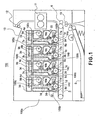
- Figure 1 is a longitudinal sectional view illustrating the general arrangement of a full-color laser beam printer 100 which is an exemplary image forming apparatus.
- the image forming apparatus 100 comprises four process cartridges 7 (7a, 7b, 7c, 7d) arranged in a horizontal direction and four developer supply cartridges 9 (9a, 9b, 9c, 9d) provided correspondingly thereto.
- the process cartridges 7 and the developer supply cartridges 9 are detachably mountable to the main assembly 100a of the apparatus of the image forming apparatus 100 independently from each other.
- the main assembly 100a of the apparatus means the entirety of the image forming apparatus 100 without the process cartridges 7 and the developer supply cartridges 9.
- the process cartridge 7 contains an electrophotographic photosensitive drum 1 (1a, 1b, 1c, 1d).
- the electrophotographic photosensitive drum (photosensitive drum) 1 is rotated by driving means (unshown) provided in the main assembly 100a of the apparatus.
- the process cartridge 7 includes a charging roller (charging means) 2 (2a, 2b, 2c, 2d), developing means 4 (4a, 4b, 4c, 4d) and cleaning means 8 (8a, 8b, 8c, 8d) which are process means provided around the photosensitive drum 1.
- the main assembly 100a of the apparatus comprises scanner units 3 (3a, 3b, 3c, 3d) and intermediary transfer members 5, respectively such that they are around the photosensitive drum 1 when the process cartridges are mounted to the main assembly.
- the developed image formed on the photosensitive drum 1 is transferred onto an intermediary transfer member 5 by primary transferring means 14 (14a, 14b, 14c, 14d).
- the primary transferring means 14 is provided in the main assembly 100a of the apparatus.
- the charging roller 2 is urged to the photosensitive drum 1 and functions to uniformly charge the surface of the photosensitive drum 1.
- the scanner unit 3 projects a laser beam onto the photosensitive drum 1 to form the electrostatic latent image on the photosensitive drum 1.
- the developing means 4 (4a-4d (4a-4d) functions to develop the electrostatic latent image with a developer into a developed image.
- the developing means 4 develops the electrostatic, latent image.
- the cleaning means 8 functions to remove the residual developer remaining on the surface of the photosensitive drum 1 after the toner image is transferred.
- the photosensitive drum 1, and the process means including the charging roller 2, the developing means 4 and the cleaning means 8 constitute a unit, that is, a process cartridge 7.
- the photosensitive drum 1 is rotated in timed relation with image formation.
- the scanner units 3 are operated sequentially for the respective process cartridges 7.
- the voltage is applied to the charging roller 2 rotated by the photosensitive drum 1 while being in contact thereto by which the peripheral surface of the photosensitive drum 1 is charged electrically to a uniform potential.
- the scanner unit 3 produces a light beam modulated in accordance with the image signal, and the peripheral surface of the photosensitive drum 1 is exposed to the image light. By doing so, an electrostatic latent image is formed on the peripheral surface of the photosensitive drum 1.
- the electrostatic latent image is developed with a developer by the developing roller 17 (17a-17d) of the developing means 4. By this, a developed image is formed on the peripheral surface of the photosensitive drum 1 by the developing roller 17.
- the developing roller 17 develops the electrostatic latent image using the developer.
- the primary transferring means 14 is supplied with a bias voltage of a polarity opposite to that of the developed image. By doing so, the developed image formed on the photosensitive drum 1 is transferred onto the intermediary transfer member 5 (primary transfer).
- the developed images (four color developed images) formed on the photosensitive drum 1 are overlaid on the intermediary transfer member 5. Thereafter, secondary transferring means 6 is press-contacted to the intermediary transfer member 5. The recording material S having been stopped at a predetermined position by the registration roller 10 is delivered to a nip formed between the intermediary transfer member 5 and the secondary transferring means 6.
- the process cartridge 7a accommodates a yellow color developer.
- the process cartridge 7b accommodates a magenta color developer.
- the process cartridge 7c accommodates a cyan color developer.
- the process cartridge 7d accommodates a black color developer. Therefore, a yellow color developed image is formed on the photosensitive drum 1a.
- a magenta color developed image is formed on the photosensitive drum 1b
- a cyan color developed image is formed on the photosensitive drum 1c
- a black color developed image is formed the photosensitive drum 1d.
- the process cartridges 7a, 7b, 7c and 7d have the same structures although the colors of the contained developers are different.
- the secondary transferring means 6 is supplied with a bias voltage of the polarity opposite from that of the developer. Therefore, the developed images on the intermediary transfer member 5 are transferred all together onto the surface of the fed recording material S.
- the recording material S is fed to the fixing device 11 and is fixed by heat and pressure.
- the recording material S is discharged onto the discharging tray 13 by discharging rollers 12. In this manner, the image forming operation is completed.
- the developer is consumed by the developing operation. With the consumption of the developer, the developer is supplied sequentially from the developer supply cartridge 9 (9a, 9b, 9c, the) which will be described hereinafter.
- the structures of the developer supply cartridges 9a, 9b the 9c and 9d are the same although the colors of the contained developer are different from each other.
- Designated by reference characters 100b is a process cartridge mounting portion having a space into which the process cartridge 7 is mounted dismountably.
- Designated by 100c is a supply cartridge mounting portion having a space into which the supply cartridge 9 is mounted dismountably.
- the mounting portion 100b and 100c are provided in the main assembly 100a of the apparatus.
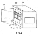
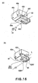
- the operator opens a cartridge cover 110 provided in the main assembly 100a of the apparatus ( Figure 5 ). Then, the operator advances the process cartridge 7 into the main assembly 100a of the apparatus along the longitudinal direction of the photosensitive drum 1 (direction of arrow A in the Figure). In addition, the operator advances the developer supply cartridge 9 into the main assembly 100a of the apparatus along the longitudinal direction of the supplying-side developer accommodating portion 33 (direction of arrow A in the Figure). Thus, the cartridges 7 and 9 are inserted in the longitudinal direction.
- the process cartridge 7 and the developer supply cartridge 9 receive driving forces from the main assembly 100a of the apparatus at a rear side of the main assembly 100a of the apparatus (leading side with respect to the entering direction.
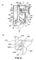
- the developer supply cartridge 9 is carried on main assembly rails 101a, 101b provided in the main assembly 100a of the apparatus at portions-to-be-guided 42a, 42b of the developer supply cartridge 9 ( Figure 2 ) when the developer supply cartridge 9 is inserted.
- the process cartridge 7 is carried on main assembly rails 102a, 102b provided in the main assembly 100a of the apparatus at portions-to-be-guided 43a, 43b ( Figure 2 ) of the process cartridge 7.
- the process cartridge 7 comprises a cleaning unit 22 and a developing unit 23 which are rotatably connected with each other.
- the cleaning unit 22 comprises the cleaner container 15 which is a frame rotatably supporting the photosensitive drum 1 and comprises a charging roller 2.
- the cleaning unit 22 further comprises cleaning means 8 in the form of cleaning blade 8e and so on.
- the cleaning blade 8e functions to remove the developer remaining on the photosensitive drum 1.
- a receiving-side developer accommodating portion 16 (developer accommodating portion) for accommodating the developer and a developing container 18 are connected with each other by ultrasonic welding or the like.
- the developing unit 23 includes the developer accommodating portion 16 and the developer container 18.
- the developing container 18 rotatably supports the developing roller 17.
- a fresh (unused) process cartridge 7 contains a predetermined amount of the developer in the developer accommodating portion 16. The developer is consumed for image formation, and the developer is supplied from the developer supply cartridge 9.
- the developing container 18 includes the developing roller 17, a developing blade 19 for regulating a layer thickness of the developer deposited on the peripheral surface of the developing roller 17, and a developer supplying roller 20 in the form of a sponge roller for supplying the developer onto the developing roller 17.
- the developing unit 23 is rotatable relative to the cleaning unit 22.
- the developer supply cartridge 9 (9a-9d) is mounted above the developing unit 23 (developer accommodating portion 16) in the main assembly 100a of the apparatus in the state that process cartridge 7 (7a-7d) is mounted to the main assembly 100a of the apparatus.
- the developer accommodating portion 16 is provided in an upper portion with a developer receiving opening 16a for receiving the developer from the supply cartridge 9.
- a receiving-side shutter 65 for opening and closing the receiving opening 16a.
- the shutter 65 opens and closes the receiving opening 16a by rotation.
- the shutter 65 is movable between a developer-reception-permitting position for opening the receiving opening 16a for receiving the developer and a developer-reception-preventing position for closing the receiving opening 16a.
- An upper portion of the shutter 65 is provided with a sealing member 67, made of urethane foam, felt or the like, for connecting the process cartridge 7 and the developer supply cartridge 9 with each other.
- the receiving opening 16a functions to receive the developer into the developer accommodating portion 16 from the supply cartridge 9.
- the process cartridge 7 is dismountably mounted to the mounting portion 100b, and the supply cartridge 9 is dismountably mounted to the mounting portion 100c thereabove.
- the process cartridge 7 and the supply cartridge 9 are detachably mountable relative to the main assembly 100a of the apparatus independently from each other.
- the sealing member 67 functions to prevent leakage of the developer through the connecting portion between the supply cartridge 9 and the process cartridge 7 when the developer is supplied from the supply cartridge 9 into the process cartridge 7.
- the sealing member 67 is provided to assure the prevention of the developer leakage, and is not inevitable.
- the supply cartridge 9 comprises a supplying-side developer accommodating portion 33 for accommodating the developer.
- the lower portion of the developer accommodating portion 33 is provided with a developer supply opening 34 which may be aligned with the receiving opening 16a.
- the developer is supplied from the inside of the developer accommodating portion 33 into the process cartridge 7. More particularly, the developer is supplied into the receiving-side developer accommodating portion 16 from the process cartridge 7.
- a screw 38 for feeding the developer. The screw 38 is rotated by receiving the training force from the main assembly 100a. By doing so, the developer is fed to the supply opening 34. Then, the developer is fed to the receiving opening 16a from the supply opening 34.
- the developer accommodating portion 33 it is provided therein with a developer feeding members 36 (36a, 36b) for feeding the developer to the screw 38.
- the shaft portion 36a is supplied with a rotational driving force by which the developer fed sheet 36b coupled with the shaft portion 36a is rotated. In this manner, the fed sheet 36b feeds the developer to the screw 38.
- a supplying-side shutter 35 for opening and/closing the opening 34.
- the opening 34 is opened and closed by rotation of the shutter 35.
- the shutter 35 is capable of take a developer-supply-permitting position where the shutter 35 opens the supply opening 34 for supplying the developer into the process cartridge 7 through the receiving opening from the developer accommodating portion 33.
- the shutter 35 can take a developer-supply-preventing position where it closes the supply opening 34.
- the lower surface of the developer accommodating portion 33 is provided with a first engageable member 31b extending downward.
- the first engageable member 31b is disposed at a trailing side of the supplying-side communication opening (T container communication opening) 44a as seen in an entering direction in which the developer supply cartridge 9 enters into the main assembly 100a of the apparatus.
- a second engageable member 31a is provided similarly.
- the first engageable member 31b is provided, and at the downstream side thereof, the second engageable member 31a is provided, with respect to the entering direction in which the supply cartridge 9 enters the main assembly 100a of the apparatus.
- Figure 6 is an exploded perspective view of the shutter 35 (supplying-side shutter portion) (rotatable member) of the supply cartridge 9.
- Figure 7 illustrates the supplying-side shutter 35 opening the supply opening 34 (a), and the supplying-side shutter 35 closing the supply opening 34 (b).
- Figure 7 also illustrates the receiving-side shutter 65 opening the receiving opening 16a (c), and the receiving-side shutter 65 closing the receiving opening 16a (d).
- Figure 8 is a front view of the supplying-side movable member (supplying-side movable portion) 32 and the shutter 35 which are coupled with each other.
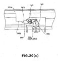
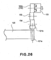
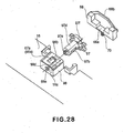
- Figure 26 illustrates a drive structure for the winding-up portion for winding up a toner seal of the supply cartridge 9.
- Figure 17 is a front view of the winding-up portion.
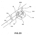
- Figure 23 is a perspective view of a shutter 35 and the parts in the neighborhood of the shutter 35.
- a lower surface 9e of the developer accommodating portion 33 is provided with a T housing 44 fixed thereto.
- the T housing 44 is provided at an upper part with a T housing opening 44d and is provided at a lower part with a T container communication opening 44a.
- the developer in the developer accommodating portion 33 is supplied into the process cartridge 7 (developer accommodating portion 16) through the opening 44d and the communication opening 44a.
- a supplying-side shutter inserting portion 44b Between the opening 44d and the communication opening 44a, there is provided a supplying-side shutter inserting portion 44b.
- the inserting portion 44b functions to rotatably support the cylindrical portion 35a of the shutter 35.
- the lower surface means the surface or side facing downward when the supply cartridge 9 is mounted to the main assembly 100a of the apparatus.
- the shutter 35 is provided witch a connecting portion 35c projecting from a lateral edge of the cylindrical portion 35a (base portion) outwardly in the axial direction of the cylindrical portion.
- the shutter 35 is provided with communication opening 35b through the periphery of the cylindrical portion 35a at the diametrically opposing positions, respectively. More particularly, the communication openings 35b are disposed opposed to the opening 34 and to the communication opening 44a with respect to a direction crossing with the axial direction.
- the cylindrical portion 35a is fitted into the shutter inserting portion 44b such that outer surface of the cylindrical portion 35a is contacted to the inner surface of the shutter inserting portion 44b. By doing so, the shutter 35 is rotatable relative to the developer accommodating portion 33.
- a cap 39 for the inserting portion of the supplying-side shutter.
- the cap 39 is provided with arm portions 39b at the opposite end portions, respectively.
- Each of the arm portion 39b has a hole portion 39c which is engaged with a retaining portion 44c in the form of a claw provided on the T housing 44. By doing so, the cap 39 is fixed on the T housing 44. And, the shutter 35 is prevented from disengaging from the T housing 44.
- the cap 39 has an opening 39a formed therein. Through the opening 39a, a connecting portion 35c of the shutter 35 is penetrated.
- a supplying-side movable member (supplying-side movable portion) 32 functioning to interrelatedly move the shutter 35 is fixed.
- the movable member 32 has an end projection 32a which is inserted into an end recess 35c1 formed in a free end surface of the shutter 35.
- the projection 32a is press-fitted into the recess 35c1.
- the movable member 32 is fixed on the shutter 35.
- the movable member 32 is integrally rotatable with the shutter 35. In other word, the shutter 35 rotates in interrelation with rotation of the movable member 32.
- the movable member 32 includes projections 32b (32b1, 32b2, 32b3, 32b4) and recesses 32c (32c1, 32c2, 32c3, 32c4) which are arranged alternately ( Figure 8 ).
- the shutter 35 is inserted into the shutter inserting portion 44b of the housing 44.
- the opening of the shutter inserting portion 44b is capped by the cap 39.
- the hole portion 39c is engaged with the retaining portion 44c of the T housing 44.
- the cap 39 is fixed to the T housing 44.
- the end projection 32a of the movable member 32 is press-fitted into the end recess 35c1 of the supplying-side shutter 35.
- the T housing 44 is mounted on the developer accommodating portion 33 by screws (unshown) or the like.
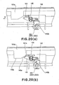
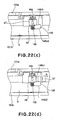
- Figure 7 is a sectional view of the shutter and the elements therearound in the state that developer supply cartridge 9 and the process cartridge 7 are mounted to or set in the image forming apparatus 100.
- Figure 7 (b) is a sectional view of the shutter and the elements therearound in the state that one of the developer supply cartridge 9 and the process cartridge 7 is taken out of the main assembly of the image forming apparatus 100a.
- the supplying-side movable member 32 receives a force from the receiving-side movable member (receiving-side movable portion) 62 of the process cartridge 7, which will be described hereinafter, to move, more particularly, to rotate in this embodiment.
- the shutter 35 rotates by 90° from the position permitting the developer supply ( Figure 7, (a )) to a position preventing the developer supply in either one of the directions indicated by arrows B and C ( Figure 7, (b) ).
- the opening 44d or the communication opening 44a of the supply cartridge 9 becomes not opposed to the communication opening 35b. By doing so, the opening 44d is closed so that supply of the developer into the process cartridge 7 is stopped.
- the opening and closing operations of the shutter of the supply cartridge 9 are carried out by rotating the shutter 35 by 90°.
- T toner seal 120 ( Figure 17 ).
- One longitudinal end 120a of the toner seal 120 is fixed to the supply opening 34 to seal the supply opening 34.
- the other end 120b of the T toner seal 120 is fixed to a circular column portion 121a of a winding-up shaft 121.
- the winding-up shaft 121 is provided with a driving force receiving portion 121b which is rotatable integrally with the circular column portion 121a.
- the driving force receiving portion 121b comprises a T driving force receiving coupling 152 for receiving a driving force from a main assembly coupling 151 provided in the main assembly 100a of the apparatus, when the supply cartridge 9 is mounted to the main assembly 100a of the apparatus. It receives the driving force from a gear portion 152a of the coupling 152 through a gear train including idler gears 153, 154 Figure 26 .
- the supply opening 34 may be sealed by the toner seal 120.
- the winding-up shaft 121 receives a driving force from the main assembly through the driving.force receiving portion 121b to rotate in the direction of arrow D, in the state that supply cartridge 9 is set in the main assembly 100a of the apparatus ( Figure 17 ).
- the winding-up shaft 121 winds the toner seal 120 up to open the supply opening 34.
- the supply opening 34 is sealed by the shutter 35.
- the discrimination whether or not the supply cartridge 9 is a fresh one is carried out by the main assembly 100a of the apparatus recognizing information stored in memory (unshown) provided in the supply cartridge 9.
- the developer supply cartridge 9 is provided with the supplying-side shutter 35. For this reason, it is not always necessary to employ the toner seal, and the developer leakage through the supply opening 34 can still be prevented. However, with the above-described structure having the toner seal, the leakage of the developer can be prevented assuredly during, for example, transportation of the developer supply cartridge.
- the supplying-side shutter 35 and the supplying-side movable member 32 are unintegral or separate members.
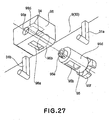
- the cap 39 is not used, and as shown in Figure 27 , the supplying-side shutter (supplying-side shutter portion) 95 is provided with disengagement prevention portion 95e of snap fit type, for example. By doing so, the shutter 95' is engaged with the hole 96e of the T housing 96 so that disengagement can be prevented. Therefore, the shutter 95 and the supplying-side movable portion 95f may be one integral structure.
- the supplying-side shutter 95 of the Figure 27 example corresponds to the above-described supplying-side shutter 35
- the T housing 96 corresponds to the T housing 44
- the supplying-side movable portion 95f corresponds to the supplying-side movable member 32
- the communication opening 95b corresponds to the communication opening 35b
- non-opening portion 95d corresponds to the non-opening portion 35d
- the T container communication opening 96a corresponds to the T container communication opening 44a
- the supplying-side shutter inserting portion 96b corresponds to the supplying-side shutter inserting portion 44b
- the T housing opening 96d corresponds to the T housing opening 44d.
- the supply cartridge 9 further includes the following structures.
- first engageable member 31b fixed at a position downstream of the supply opening 34 (supplying-side movable member 32) with respect to the advancing direction in which the supply cartridge 9 enters the main assembly 100a of the apparatus.
- the first engageable member 31b moves the regulating member 68 which will be described hereinafter, prior to the shutter 35 opening the supply opening 34.
- the regulating member 68 releases the regulating operation of the regulating member 68.
- This enables movement of the receiving-side movable member 62.
- it is brought into engagement with first receiving-side operating portions 62b1, 62b3 of the movable member 62 to rotate the movable member 62. This moves the receiving-side shutter 65 from the developer-reception-preventing position to the developer-reception-permitting position.
- the developer supply cartridge 9 comprises a second engageable member 31a fixed at a position downstream of the supply opening 34 (supplying-side movable member 32) with respect to a dismounting direction in which the developer supply cartridge 9 is removed from the main assembly of the apparatus 100.
- the second engageable member 31a is brought into contact to the regulating member 68 to move (rotate) the regulating member 68 after the shutter 35 closes the supply opening 34. By this, it releases the regulating operation of the regulating member 68. Thus, it permits the movement of the movable member 62.
- the shutter 65 is moved from the developer-reception-permitting position to the developer-reception-preventing position.
- the supplying-side movable member 32 extends in a direction perpendicular to the bottom side (lower surface) 9e of the supply cartridge 9.
- the movable member 32 is rotatable about a horizontal axis parallel with the lower surface 9e.
- the supplying-side shutter 35 is in the form of a rotatable cylindrical which is rotatable about a horizontal axis parallel with the lower surface 9e of the supply cartridge 9.
- the cylindrical opening, extending along the longitudinal direction of the cylindrical shape, of the supplying-side shutter 35 opposes the developer supply opening 34. By doing so, the developer supply opening 34 is opened. The portion of the cylindrical other than the cylindrical opening closes the supply opening 34 by opposing the receiving opening 16a.
- the supplying-side movable member 32 comprises a supplying-side operating portion in the form of projections (32b1, 32b2, 32b3, 32b4) which are engaged with projections 62b1, 62b3 (first receiving-side operating portion) and bifurcated projections 62b2, 62b4 (second receiving-side operating portion) to receive rotating forces. By doing so, the supplying-side shutter 35 is rotated.
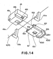
- Figure 9 is an exploded perspective view of the shutter of the process cartridge 7 and the elements therearound.
- Figure 10 is a front view illustrating a state of connection between the receiving-side movable member 62 and the receiving-side shutter 65 (receiving-side shutter portion) (rotatable member).
- Figure 18 is a front view of the winding-up portion for winding the toner seal of the process cartridge.
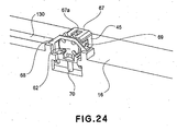
- Figure 24 is a perspective view of the shutter of the process cartridge 7 and the elements therearound.
- Figure 25 illustrates a driving structure for the winding-up portion.
- the shutter mechanism of the process cartridge 7 has the structures similar to those of the shutter mechanism of the supply cartridge 9.
- the developing-device housing 45 corresponds to the T housing 44.
- the developing-device housing opening 45d corresponds to the T housing opening 44d.
- the developing container communication opening 45a corresponds to the T container communication opening 44a.
- the development shutter inserting portion 45b corresponds to the supplying-side shutter inserting portion 44b.
- the receiving-side shutter 65 corresponds to the supplying-side shutter 35.
- the cylindrical portion 65a corresponds to the cylindrical portion 35a;
- the connecting portion 65c corresponds to the connecting portion 35c;
- the description of the corresponding portions of the process cartridge will be omitted for simplicity.
- a movable member 62 fixed to a free end of the shutter 65 functions to move the shutter 65.
- the shutter 65 is interrelated with the movement (rotation) of the movable member 62.
- the movable member 62 is provided with projections 62b (62b1, 62b2, 62b3, 62b4) and recesses 62c (62c1, 62c2, 62c3, 62c4) to apply a rotating force to the supply cartridge 9 with the mounting and demounting operations of the process cartridge 7 relative to the main assembly 100a of the apparatus.
- the projection 62b is arranged along rotational moving direction of the movable member 62.
- the projection 62b2 is provided at the center portion thereof with a recess 62d1 so that it constitutes a bifurcated projection.
- the projection 62b4 is provided at the center portion thereof with a recess 62d2 so that it constitutes a bifurcated projection.
- the projections 62b2, 62b4 are engageable with the projections 32b (32b1, 32b2, 32b3, 32b4) of the movable member 32.
- the projections 62b1 - 62b4 constitute a receiving-side operating portion. More particularly, the projections 62b1, 62b3 constitute a first receiving-side operating portion, and the projections 62b2, 62b4 constitute a second receiving-side operating portion.
- the recesses 62d1, 62d2 are provided to prevent the interference between the projection 32b and the projections 62b2, 62b4. Referring to Figure 10 , the parts of the projection 62b2 and 62b4 are enclosed by chain lines.
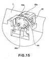
- the developer accommodating portion 16 is further provided with a regulating member 68 for regulating rotation of the movable member 62.
- the regulating member 68 is made slidable in the vertical direction (direction of arrow E) by claw portions 71a, 72a of the slide rails 71, 72 provided in the developer accommodating portion 16.
- the regulating member 68 is normally urged in a upward direction by a spring force (elastic force) of a compression spring 70 provided between the developer accommodating portion 16 and the regulating member 68.
- the regulation recess 68a is sequentially engageable with the projections 62b (62b1, 62b2, 62b3, 62b4) of the movable member 62. By doing so, the rotation of the movable member 62 is regulated. In other word, by the engagement between the projection 62b and the recess 68a, the rotation of the movable member 62 is regulated or prevented.
- the topmost surface of the housing 45 is provided with a sealing member 67 having an opening 67a corresponding to the communication opening 45a.
- the shutter 65 is inserted into the shutter inserting portion 45b of the housing 45.
- the opening of the shutter inserting portion 45b is capped with the cap 69.
- the hole portion 69c of the cap 69 is engaged with a retaining portion 45c of the housing 45.
- the shutter 65 is fixed to the housing 45.
- the end projection 62a of the movable member 62 is press-fitted into the end recess 65c1 of the shutter 65.
- the regulating member 68 is engaged with the claw portions 71a, 72a of the slide rail 71, 72 on the outside of the developer accommodating portion 16.
- the spring 70 is mounted between the regulating member 68 and the developer accommodating portion 16.
- the sealing member 67 is mounted to the communication opening 45a side of the housing 45.
- the developing-device housing 45 is fixed to the developer accommodating portion 16 by screws (unshown) or the like.
- the shutter 65 opens and closes similarly to the.above-described shutter 35. With each 90° rotation of the receiving-side shutter 65, the process cartridge 7 alternately becomes capable of developer reception from the developer supply cartridge 9 (developer-reception-permitting position, Figure 7, (c)) and becomes incapable of developer reception a (developer-reception-preventing position, 7, (d)).
- the receiving opening 16a is opened and closed by the rotation of the shutter 65 in interrelation with the 90° rotation of the receiving-side movable member 62.
- a D toner seal 130 ( Figure 18 ).
- One longitudinal end 130a of the D toner seal 130 is fixed to the developer accommodating portion 16 and seals the receiving opening 16a.
- the other end 130b of the D toner seal 130 is fixed to the circular column portion 131a of the winding-up shaft 131.
- a rotatable driving force receiving portion 131b which is rotatable integrally with the circular column portion 131a.
- the development driving force reception coupling 156 receives the driving force from the main assembly coupling 155, for the developing operation, provided in the main assembly of the apparatus 100.
- the driving force receiving portion 131b receives the driving force through the gear train including idler gears 157, 158, 159 from the gear portion 156a of the coupling 156.
- the receiving opening 16a may be sealed by the above-described toner seal 130.
- the winding-up shaft 131 receives the driving force from the main assembly through the driving force receiving portion 131b.
- Whether the process cartridge 7 is a fresh one or not is discriminated by the main assembly 100a of the apparatus detecting information stored in memory (unshown) provided in the process cartridge 7.
- the winding-up shaft 131 winds the toner seal 130 up to opening the receiving opening 16a.
- the receiving opening 16a is sealed by the shutter 65.
- the process cartridge is also provided with the receiving-side shutter 65 similarly to the developer supply cartridge. For this reason, the leakage of the developer from the developer receiving opening 16a can be prevented sufficiently even if the toner seal is not employed. However, with the structure employing the above-described toner seal, the possible developer leakage during transportation of the process cartridge can be prevented assuredly.
- the receiving-side shutter 65 and the receiving-side movable member 62 are unintegral or separate members.
- the cap 69 is not used, but the receiving-side shutter (receiving-side shutter portion) 97 is provided with a disengagement prevention portion 97e such as snap fit is provided, and the shutter 97 is engaged with a hole 98e of the developing-device housing 98 to prevent the disengagement.
- the shutter 97 and the receiving-side movable portion 97f may be made integral.
- the shutter 97 corresponds to the above-described shutter 65; the movable member 97f corresponds to the movable member 62; and the developing-device housing 98 corresponds to the developing-device housing 45.
- the communication opening 97b corresponds to the communication opening 65b; and the non-opening portion 97d corresponds to the non-opening portion 65d.
- the developing container communication opening 98a corresponds to the developing container communication opening 45a; the development shutter inserting portion 98b corresponds to the development shutter inserting portion 45b; and the developing-device housing opening 98d corresponds to the developing-device housing opening 45d. Therefore, the detailed description of these elements will be omitted for the sake of simplicity.
- the opening 44d and communication opening 44a of the T housing are positioned such that they are not opposed to the communication opening 35b of the supplying-side shutter 35 (the state shown in (b) in Figure 7 ) (developer-reception-preventing position). Therefore, the supply of the developer into the process cartridge 7 is prevented (closed state).
- the movable member 62 When the process cartridge 7 is mounted to the main assembly 100a of the apparatus in the state that supply cartridge 9 is not mounted to the main assembly 100a of the apparatus, the movable member 62 receives no force from anywhere. Therefore, the shutter 65 does not rotate. For this reason, the process cartridge 7 remains in the closed state in which the developer reception is prevented.
- the regulation recess 68a of the regulating member 68 and the projections 62b (62b1 or 62b3) of the movable member 62 are in engagement with each other. Therefore, the movable member 62 is kept regulated (the rotation (movement) is prevented).
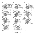
- the operator inserts the supply cartridge 9 into the main assembly 100a of the apparatus while the portions-to-be-guided 42a, 42b set on the main assembly rails 101a, 101b (in the direction indicated by an arrow A in (k) of Figure 11 ).
- the engaging portion 31a1 slides on the flat surface portion 68b2 of the regulating member 68. And, the engaging portion 31a1 is engaged with the projection 62b (62b1 or 62b3) of the movable member 62 to rotate the movable member 62 in the couterclockwise direction ((g) of Figure 11 ). With the rotation of the movable member 62, the receiving-side shutter 65 fixed thereto is also rotated in the couterclockwise direction together with the movable member 62. By this, the communication opening 65b of the shutter 65 is communicated with the developing-device housing opening 45d and the communication opening 45a. More particularly, the shutter 65 is now placed in the developer-reception-permitting position ((c) of Figure 7 ). The recess 62c (62c1 or 62c3 in Figure 10 ) is provided to receive the engaging portion 31a1 when the engaging portion 31a1 is engaged with the projection 62b (62b1 or 62b3).
- the engaging portion 31a1 of the supply cartridge 9 is disengaged from the inclined surface portion 68b3 of the guide surface 68b.
- the projection 62b (62b2 or 62b4 in Figure 10 ) is brought into engagement with the regulation recess 68a of the regulating member 68.
- the movable member 62 restores the regulated position where the rotation is prevented ((c) of Figure 11 ).
- the supply cartridge 9 is further advanced into the main assembly 100a of the apparatus.
- the bifurcated projection 62b (62b2 or 62b4 in Figure 10 ) of the movable member 62 is engaged with the projection 32b (32b1 or 32b3 of Figure 8 ) and the recess 32c (32c1 or 32c3 of Figure 8 ) of the movable member 32.
- the rotation of the movable member 62 is regulated or prevented by the regulating member 68. Therefore, the movable member 32 rotates in the couterclockwise (direction of arrow I in (c) of Figure 11 ) by the force received from the movable member 62 with the entering movement of the supply cartridge 9.
- the shutter 35 fixed thereto also rotates in the couterclockwise.
- the communication opening 35b of the supplying-side shutter 35 is brought into fluid communication (the developer can flow therethrough) with the housing opening 44d and the communication opening 44a ((c) - (b) of Figure 11 ).
- the shutter 35 of the supply cartridge 9 is now in the developer-supply-permitting position.
- the process cartridge 7 and the supply cartridge 9 are detachably mountable to the main assembly 100a of the apparatus independently from each other.
- the process cartridge 7 includes the photosensitive drum 1 and the developing roller 17 for developing the electrostatic latent image formed on the photosensitive drum 1 with the developer.
- the process cartridge 7 includes the receiving-side shutter 65 movable between the developer-reception-permitting position for opening the developer receiving opening 16a for receiving the developer and the developer-reception-preventing position for closing the receiving opening 16a.
- the process cartridge 7 includes the receiving-side movable member 62 which is movable in interrelation with the shutter 65 and which includes receiving-side operating portions 62b2 and 62b4 which are placed at the operating position when the shutter 65 is at the developer-reception-permitting position.
- the process cartridge 7 includes the regulating member 68 for regulating the movement of the movable member 62 when the operating portion 62b2 or 62b4 is at the operating position ((e) of Figure 11 ).
- the operating position is the position where the operating portion 62b2 or 62b4 is in engagement with the projection 32b of the supplying-side movable member 32, and the supplying-side movable member 32 is moved (rotated) by the relative movement between the supplying-side movable member 32 and the receiving-side movable member 62.
- the operating portion 62b2 or 62b4 is at the topmost position in the operating position ((a) - (e)).
- the supply cartridge 9 includes the supplying-side developer accommodating portion 33 for accommodating the developer.
- the supply cartridge 9 includes the T housing opening 44d for supplying the developer from the developer accommodating portion 33 into the process cartridge 7 through the receiving opening 16a, and the supplying-side shutter 35 is movable between the toner-supply-permitting position where the T housing opening 44d and the communication opening 44a are in communicating relation with each other and the developer-supply-preventing position for closing the T housing opening 44d and the communication opening 44a.
- the developer supply cartridge 9 includes the movable member 32 having the projection 32b which is engageable with the operating portion 62b2 in the state of being regulated at the operating position.
- the movable member 32 moves interrelatedly the shutter 35 from the toner-supply-preventing position to the toner-supply-permitting position by the operating portion 62b2 or 62b4 engages with the projection 32b ((d) - (a) of Figure 11 ).
- the portion-to-be-positioned 40 of the supply cartridge 9 abuts the main assembly supporting shaft 103 provided in the main assembly 100a of the apparatus ((b) of Figure 13 ).
- the portion-to-be-positioned 40 is provided on the leading side end surface of the supply cartridge 9 with respect to the entering direction of the supply cartridge 9 into the main assembly 100a of the apparatus.
- the 90° rotating operation of the shutter 35 is completed, so that mounting of the supply cartridge 9 to the main assembly 100a of the apparatus is completed.
- the rotation of the supplying-side shutter 65 stops.
- the communication opening 65b is at such a position that it opposes the T housing opening 45d and the communication opening 45a ((c) of Figure 7 ) (developer-supply-permitting position).
- the developer supply opening 34 is now in the opening state, and the developer can be supplied into the process cartridge 7 ((a) of Figure 11 ).
- the operations of the receiving-side movable member 62, the receiving-side shutter 65 and the regulating member 68 are as follows.
- the movable member 62 functions to interrelatedly move the shutter 65 between the developer-reception-permitting position and the developer-reception-preventing position.
- the movable member 62 includes the receiving-side operating portion (second receiving-side operating portion) (bifurcated projections 62b2 and 62b4) which is at the operating position when the shutter 65 is placed at the developer-reception-permitting position.
- the regulating member 68 regulates the movement (rotation) of the movable member 62 in the state that said receiving-side operating portion is at the operating position.
- the movable member 32 of the cartridge 9 has the following structures.
- the movable member 32 is moved (rotated) by engaging with the receiving-side operating portion (projection 62b2, 62b4) of the movable member 62 regulated or confined by the regulating member 68 placed at the operating position.
- the movable member 32 interrelatedly moves the shutter 35 from the developer-supply-preventing position to the developer-supply-permitting position. By doing so, the shutter 35 opens the supply opening 34.
- the receiving-side operating portion which is placed at operating position when the shutter 65 is placed at the developer-reception-permitting position.
- the movable member 32 is moved by the engagement with the receiving-side operating portion (projection 62b2, 62b4) to move the shutter 35 from the developer-supply-preventing position to the developer-supply-permitting position. Therefore, when the supply cartridge 9 enters the main assembly 100a of the apparatus, the supply opening 34 opens only when the shutter 65 is placed at the developer-reception-permitting position, that is, only when the receiving opening 16a is open. For this reason, it can be avoided that supply opening 34 opens despite the receiving opening 16a is closed. Thus, the leakage of the developer from the supply opening 34 can be prevented.
- the supply opening 34 never opens unless the process cartridge 7 is mounted to the main assembly 100a of the apparatus.
- the supply cartridge 9 is advanced into the main assembly 100a of the apparatus while being carried on the main assembly rails (main assembly side guide) 101a, 101b at the portions-to-be-guided 42a, 42b. It is desirable that force required for the insertion is small while the positioning of the supply cartridge 9 is assured. From this standpoint, there is provided a clearance which is larger than at the clearance between the main assembly supporting shaft 103 and the portion-to-be-positioned 40.
- the portion-to-be-guided 42b which is closer to the movable member 32 as seen in the cross-sectional direction (left side with respect to the direction in which the view of Figure 2 is seen) is guided.
- the main assembly rail 101b functions to regulate a vertical deviation and a leftward deviation of the supply cartridge 9.
- the main assembly rail 101a regulates downward and rightward deviations of the developer supply cartridge 9.
- the portion-to-be-guided 42b includes a side portion-to-be-regulated 42b3, an upper side portion-to-be-regulated 42b1 and a lower portion-to-be-regulated 42b2.
- the portion-to-be-regulated 42b3, the portion-to-be-regulated 42b1 and the portion-to-be-regulated 42b2 are regulated by the main assembly rail 101b provided the main assembly 100a of the apparatus.
- the portion-to-be-regulated 42b1 is prevented from upward movement by an upper surface regulating portion 101b1 of the main assembly rail 101b.
- the lower portion-to-be-regulated 42b2 is regulated in the downward movement by the lower surface regulating portion 101b2 of the main assembly rail 101b.
- the side portion-to-be-regulated 42b3 is regulated in the lateral movement by the side surface regulating portion 101b3 of the main assembly rail 101b.
- the portion-to-be-guided 42b is set so as to be guided by the main assembly rail 101b at least during the operations of the supplying-side shutter 35, the receiving-side shutter 65 and the regulating member 68, shown in (k) - (a) of Figure 11 .
- the operations are the opposite from those described above. More particularly, the operations are in the order of (a) - (b) - (c) - (d) - (e) - (f) - (g) - (h) - (i) - (j) - (k).
- the supplying-side movable member 32, the supplying-side shutter 35, the regulating member 68, the receiving-side movable member 62, and the receiving-side shutter 65 operate.
- the supply cartridge 9 includes the developer accommodating portion 33 for accommodating the developer.
- the supply cartridge 9 includes the supplying-side shutter 35 movable between the developer-supply-permitting position for opening the developer supply opening 34 for supplying the developer from the developer accommodating portion 33 into the process cartridge 7 through the developer receiving opening 16a and the developer-supply-preventing position for closing the developer supply opening 34.
- the developer supply cartridge 9 includes the supplying-side movable member 32 (supplying-side movable portion) having the projection 32b engageable with the operating portion 62b2 or 62b4 which is regulated or confined to be at the operating position,
- the movable member 32 is moved (rotated) by the engagement of the operating portion 62b2 with'the projection 32b with the movement of the supply cartridge 9 to remove from the main assembly 100a of the apparatus, to interrelatedly move the supplying-side shutter 35 from the developer-supply-permitting position to the developer-supply-preventing position ((a) - (e) in Figure 11 ).
- the shutter 65 of the process cartridge 7 remaining set in the main assembly 100a of the apparatus is interrelatedly closed by the dismounting operation of the supply cartridge 9 from the main assembly 100a of the apparatus.
- the shutter 65 of the receiving opening 16a of the process cartridge 7 keeps closed.
- the opening 16a of the shutter 65 is kept closed assuredly.
- the movable member 62 is movable to interrelatedly move the receiving-side shutter 65 between the developer-reception-permitting position and the developer-reception-preventing position.
- the movable member 62 includes the receiving-side operating portion (second receiving-side operating portion) (projections 62b2 and 62b4) which is at the operating position when the shutter 65 is placed at the developer-reception-permitting position.
- the regulating member 68 regulates the movement of the movable member 62 when the operating portion (projection 62b2 or 62b4) is at the operating position.
- the movable member 32 of the supply cartridge 9 is moved by the engagement with the receiving-side operating portion (projection 62b2 or 62b4) of the movable member 62 which is regulated or confined at the operating position by the regulating member 68. And, the movable member 32 interrelatedly moves the shutter 35 from the developer-supply-permitting position to the developer-supply-preventing position.
- the movable member 32 is moved (rotated) by the engagement with the receiving-side operating portion (second receiving-side operating portion) (projection 62b2 or 62b4) of the movable member 62 which is regulated or confined at the operating position by the regulating member 68. Therefore, according to this embodiment, when the supply cartridge 9 is removed from the main assembly 100a of the apparatus, the receiving opening 16a is closed after the supply opening 34 is closed. Thus, when the supply cartridge 9 is removed from the main assembly 100a of the apparatus, it would not happen that supply opening 34 is closed after the receiving opening 16a is closed.
- the movable member 62 includes the first receiving-side operating portion 62b1 or 62b3 which is at the operating position when the shutter 65 takes the developer-reception-preventing position, the second receiving-side operating portion 62b2 or 62b4 which is at the operating position when the receiving-side shutter 65 takes the developer-reception-permitting position.
- the regulating member 68 regulates the rotation of the movable member 62 when the first operating portion 62b1 or 62b3 or second operating portion 62b2 or 62b4 is placed at the operating position.
- the engageable member (second engageable member) 31a is brought into contact to the regulating member 68 which regulates the rotation of the movable member 62 by the first operating portion 62b1 or 62b3 placed at the operating position prior to the supply shutter 35 opening the supply opening 34.
- the engageable member 31a moves the regulating member 68 downwardly against the elastic force of the spring 70. By this, it releases the regulating operation of the regulating member 68.
- the engageable member 31a permits movement of the movable member 62.
- the engageable member 31a is engaged with the first operating portion 62b1 or 62b3 to rotate the movable member 62, in interrelation with which the shutter 65 is moved from the developer-reception-preventing position to the developer-reception-permitting position. That is, the receiving opening 16a is opened.
- the engageable member 31a is brought into contact to the regulating member 68 which regulates (prevents) the rotation of the movable member 62 by the second receiving-side operating portions 62b2 or 62b4 placed at the operating position and moves the regulating member 68 downwardly against the elastic force, after the supplying-side shutter 35 closes the supply opening 34. By this, it releases the regulating operation of the regulating member 68.
- the engageable member 31a permits movement of the movable member 62.
- the engageable member 32a rotates the shutter 35 from the developer-reception-permitting position to the developer-reception-preventing position in interrelation with rotation of the movable member 62 caused by engaging with the second operating portion 62b2 or 62b4. That is, the receiving opening 16a is closed.
- the engageable member (second engageable member) 31a is disposed fixedly at a position downstream of the supply opening 34 (supplying-side movable member 32) with respect to the direction in which the supply cartridge 9 enters the main assembly 100a of the apparatus.
- the movable member 32 rotates by engagement with the movable member 62 which is regulated by the regulating member 68 confining the second operating portion 62b2 or 62b4 at the operating position, after the receiving-side shutter 65 opens the receiving opening 16a.
- the supplying-side movable member 32 moves the supplying-side shutter 35 from the developer-supply-preventing position to the developer-supply-permitting position in interrelation with the rotation thereof. That is, the supply opening 34 is opened.
- process cartridge 7 is mounted to the main assembly 100a of the apparatus in the state that supply cartridge 9 is set in the main assembly 100a of the apparatus.
- the housing opening 45d of the process cartridge 7 and the communication opening 45a are not opposed to the communication opening 65b ((d) of Figure 7 ). That is, the shutter 35 takes the developer-supply-preventing position. Therefore, the receiving opening 16a is closed by the shutter 35, in which state the developer cannot be received from the supply cartridge 9.
- the regulation recess 68a of the regulating member 68 is in engagement with the projection 62b (62b1 or 62b3) of the movable member 62. Therefore, the rotation (movement) of the movable member 62 is regulated or prevented.
- the movable member 32 does not receive any force. Therefore, the shutter 35 does not rotate.
- the supply opening 34 is closed, and in the state, the developer supply to the process cartridge 7 is not possible. That is, the shutter 35 is kept at the developer-supply-preventing position.
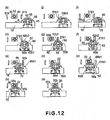
- the portions-to-be-guided 43a 43b are placed on the main assembly rails 102a, 102b, and the process cartridge 7 is advanced into the main assembly 100a of the apparatus in the direction indicated by an arrow A in (k) of Figure 12 ).
- the engaging portion 31b1 slides on the flat surface portion 68b2 of the regulating member 68 to engage with the projection 62b (62b1 or 62b3) of the movable member 62, by which the movable member 62 is rotated in the clockwise direction ((g) of Figure 12 ).
- the shutter 65 With the rotation of the movable member 62, the shutter 65 fixed thereto also rotates in the clockwise directions.
- the communication opening 65b of the shutter 65 is opposed to and communicated with the housing opening 45d and the (communication opening 45a.
- the recess 62c (62c1 or 62c3 in Figure 10 ) is provided to receive the engaging portion 31a1 when the engaging portion 31b1 is engaged with the projection 62b (62b1 or 62b3).
- the shutter 65 When the process cartridge 7 is advanced to such a position that engagement between the engaging portion 31b1 and the movable member 62 is released, the shutter 65 has been rotated by 90°. Then, the rotation of the shutter 65 stops. At this time, the communication opening 65b is opposed to the housing opening 45d and the communication opening 45a (developer-supply-permitting position).
- the shutter 65 of the process cartridge 7 opens so that process cartridge 7 is capable of receiving the developer from the supply cartridge 9 ((f) of Figure 12 ).
- the process cartridge 7 is further advanced into the main assembly 100a of the apparatus. Then, the projection 62b (62b2 or 62b4 Figure 10 in) of the movable member 62 is engaged with the projection 32b (32b1 or 32b3 in Figure 8 ) and the recess 32c (32c2 or 32c4 in Figure 8 ) of the movable member 32. At this time, the rotation of the movable member 62 is regulated or prevented by the regulating member 68. Therefore, the movable member 32 receives the force from the movable member 62 to rotate in the clockwise direction (arrow J in (c) of Figure 12 ). With the rotation of the movable member 32, the shutter 35 fixed thereto also rotates in the clockwise direction. Then, the communication opening 35b of the shutter 35, is opposed to the T housing opening 44d and the communication opening 44a ( Figures 12 (c) - (b) ).
- the portion-to-be-positioned of the process cartridge 7 is abutted to the main assembly supporting shaft (unshown) provided in the main assembly 100a of the apparatus.
- the 90° rotation the shutter 35 is completed.
- the communication opening 35b is now positioned to oppose the housing T opening 44d and the communication opening 44a ((a) of Figure 7 ).
- the supply opening 34 is also opened, and therefore, the developer supply to the process cartridge 7 is permitted ((a) of Figure 12 ).
- the process cartridge 7 includes the receiving-side movable member 62 which will be described below.
- the movable member 62 includes the first receiving-side operating portion (projection) 62b3, 62b1 which are placed at the operating position when the receiving-side shutter 65 is placed at the developer-supply-preventing position, and the second receiving-side operating portion (projection) 62b2, 62b4 which are placed at the operating position when the receiving-side shutter 65 is placed at the developer-supply-permitting position
- the movable member 62 moves the shutter 65 interrelatedly.
- the movement of the movable member 62 is regulated by the regulating member 68 with the first operating portion 62b3, 62b1 placed at the first operating position.
- the movable member 62 moves downwardly by the regulating member 68 contacting the first engageable member 31b, when the process cartridge 7 enters the main assembly 100a of the apparatus. By doing so, the movable member 62 is released from the regulating member 68 to become movable (rotatable). Then, movable member 62 moves interrelatedly the receiving-side shutter 65 to the developer-supply-permitting position by the movement thereof caused by the first operating portion 62b3, 62b1 contacting the first engageable member 31b. The movement of the movable member 62 is regulated or confined by the regulating member 68 with the second operating portion 62b2, 62b4 placed at the operating position.
- the movable member 62 moves the receiving-side shutter 65 to the developer-supply-permitting position in interrelation with the movement (rotation) of the supplying-side movable member 32 caused by engagement of the second operating portion 62b2 62b4 with the supplying-side movable member 32.
- the first engageable member 31b is brought into contact to the regulating member 68 which regulates or confines the movement of the movable member 62 in the state that shutter 65 is at the developer-supply-preventing position. And, the regulating member 68 is moved downwardly. By doing so, the movable member 62 releases the regulating action of the regulating member 68. By this, the movable member 62 becomes movable (rotatable). Subsequently, the first engageable member 31b moves the receiving-side shutter 65 to the permitting position in interrelation with the movement (rotation) of the movable member 62 caused by contacting to the first engageable member 31b.
- the movable member 32 is engaged with the operating portion 62b2, 62b4 of the movable member 62 regulated or confined at the operating position.
- the movable member 32 moves the shutter 35 from the developer-supply-preventing position to the developer-supply-permitting position.
- the movable member 62 includes the first receiving-side operating portion 62b1 or 62b3 placed at the operating position with the shutter 65 placed at the developer-reception-preventing position, and the second receiving-side operating portion 62b2 or 62b4 placed at the operating position with the shutter 65 placed at the developer-reception-permitting position.
- the regulating member 68 regulates or prevents the movement the rotation) of the movable member .62 when the first receiving-side operating portion 62b1 or 62b3 is placed at the operating position, or when the second receiving-side operating portion 62b2 or 62b4 is placed at the operating position.
- the regulating member 68 When the process cartridge 7 enters the main assembly 100a of the apparatus, the regulating member 68 is contacted to the engageable member (first engageable member) 31b to release the movable member 62 from the regulating member 68, so that movable member 62 becomes movable (rotatable).
- the shutter 65 is moved to the developer-reception-permitting position in interrelation with the movement (rotation) of the first operating portion 62b1 or 62b3 caused by the contact by the engageable member 31b. Subsequently, the movement of the movable member 62 is again regulated by the regulating member 68 when the second operating portion 62b2 or 62b4 is placed at the operating position.
- the second operating portion 62b2 or 62b4 is engaged with the movable member 32 to move (rotate) it, and the supplying-side shutter 35 is moved to the developer-supply-permitting position in interrelation with the movement (rotation) of the movable member 32. That is, the supply opening 34 is opened.
- the engageable member (first engageable member) 31b is contacted to the regulating member 68 which regulates the movement of the movable member 62 with the first operating portion 62b1 or 62b3 placed at the operating position.
- the movable member 62 is released from the regulating member 68.
- the engageable member 31b is contacted to the first operating portion 62b1 or 62b3 to move the movable member 32, in interrelation with which the shutter 65 is moved to the developer-reception-permitting position. In this manner, the receiving opening 16a is opened.
- the supplying-side movable member 32 is moved (rotated) by engagement with the second receiving-side operating portion 62b2 or 62b4 of the movable member 62 which is regulated or confined by the regulating'member 68 placed at the operating position, after the engageable member 31b moves the shutter 65 to the developer-reception-permitting position.
- the movable member 32 moves (rotates) interrelatedly the shutter 35 from the developer-supply-preventing position to the developer-supply-permitting position. By doing so, the supply opening 34 is opened.
- the first operating portion 62b1 62b3 is contacted to the engageable member 31b to move (rotate), in interrelation with which the shutter 65 is moved to the developer-reception-permitting position.
- the second operating portion 62b2 or 62b4 is brought into engagement with the movable member 32.
- the movable member 32 moves (rotates), in interrelation with which the shutter 35 is moved to the developer-supply-permitting position. That is, the supply opening 34 is opened.
- the supply opening 34 is opened only after the receiving opening 16a is opened. Therefore, the supply opening 34 never opens in the state that receiving opening 16a is closed. Thus, according to this embodiment, when the process cartridge 7 enters the main assembly 100a of the apparatus, the leakage of the developer through the supply opening 34 can be avoided.
- the receiving opening 16a when the process cartridge 7 enters the main assembly 100a of the apparatus, the receiving opening 16a is not opened unless the supply cartridge 9 is mounted to the main assembly 100a of the apparatus. In this manner, the receiving opening 16a will never be opened in the state that supply cartridge 9 is not mounted to the main assembly 100a of the apparatus.
- the operations are opposite. That is, referring to Figure 12 , the order of operations is (a) - (b) - (c) - (d) - (e) - (f) - (g) - (h) - (i) - (j) - (k).
- the movable member 32, the supplying-side shutter 35, the regulating member 68, the movable member 62 and the receiving-side shutter 65 are operated in this order.
- the process cartridge 7 detachably mountable to the main assembly 100a of the apparatus includes the receiving-side shutter 65.
- the shutter 65 is movable between the developer-reception-permitting position for opening the receiving opening 16a for receiving the developer to be used by the developing roller 17 for development and the developer-reception-preventing position for closing the developer receiving opening 16a.
- the shutter 65 is provided with the receiving-side movable member 62 which is rotatable in interrelation with the shutter 65 so that shutter 65 is movable between the developer-reception-permitting position and the developer-reception-preventing position.
- the movable member 62 includes the receiving-side operating portion 62b2 or 62b4 which is placed at the operating position when the shutter 65 is placed at the developer-reception-permitting position.
- the movable member 62 further includes the regulating member 68 for regulating the movement of the movable member 62 when it is placed at the operating position.
- the developer supply cartridge 9 which is detachably mountable to the main assembly of the apparatus to supply the developer to the process cartridge 7 includes the developer accommodating portion 16 for accommodating the developer.
- the developer supply cartridge 9 further includes the supplying-side shutter 35.
- the shutter 35 is movable between the developer-supply-permitting position for opening the supply opening 34 for supplying the developer into the process cartridge through the receiving opening 16a from the developer accommodating portion 16 and the developer-supply-preventing position for closing the supply opening 34. Furthermore, it includes the engageable member (first engageable member) 31b.
- the first engageable member 31b is contacted to the regulating member 68 which regulates or confines the movement (rotation) of the movable member 62 with the shutter 65 placed at the developer-reception-preventing position, when the process cartridge 7 enters the main assembly of the apparatus 100.
- the regulating member 68 By releasing the movable member 62 from the regulating member 68, the movement of the movable member 62 is enabled.
- the first engageable member 31b is contacted to the movable member 62 to move the movable member 62, in interrelation with which the shutter 65 is moved to the description developer-reception-permitting position.
- the developer supply cartridge includes the supplying-side movable member 32.
- the movable member 32 When the process cartridge 7 enters the main assembly of the apparatus 100, the movable member 32 is moved (rotated) by engagement with the operating portion 62b2 or 62b4 of the movable member 62 which is regulated or confined by the regulating member 68 having the operating portion 62b4 or 62b2 placed at the operating position.
- the movable member 32 moves interrelatedly the supplying-side shutter 35 from the developer-supply-preventing position to the developer-supply-permitting position.
- the receiving-side movable member 62 is constructed as follows.
- the movable member 62 includes the operating portion (projection) 62b2, 62b4 which is placed at the operating position when the shutter 65 is placed at the developer-reception-permitting position.
- the movable member 62 moves the shutter 65 interrelatedly.
- the movable member 62 is regulated or prevented from movement by the regulating member 68 placed at the operating position, where the operating portion 62b2 is engaged with the projection 32b.
- the movable member 62 is moved to move the shutter 35 to the developer-supply-preventing position.
- the movable member 62 becomes movable (rotatable) by the regulating member 68 contacting to the first engageable member 31b.
- the movable member 62 is moved by the operating portion (projection) 62b2, 62b4 contacting to the first engageable member 31b, in interrelation with which the shutter 65 is moved to the developer-reception-preventing position.
- the supplying-side shutter 35 of the supply cartridge 9 which remains in the main assembly 100a of the apparatus is closed automatically by the dismounting operation of the process cartridge 7 from the main assembly 100a of the apparatus.
- the receiving-side movable member 62 includes the receiving-side operating portion 62b2, 62b4 which is placed at the operating position with the shutter 65 placed at the developer-reception-permitting position.
- the movable member 62 functions to interrelatedly move the shutter 65 between the developer-reception-permitting position and the developer-reception-preventing position.
- the receiving-side operating portion 62b2, 62b4 of the movable member 62 which is regulated or confined by the regulating member 68 placed at the operating position, is engaged with the supplying-side movable member 32 thereby to move (rotate) the movable member 32.
- the movable member 32 moves interrelatedly the supplying-side shutter 35 to the developer-supply-preventing position. That is, the supply opening 34 is closed. Subsequently, the movable member 62 is released from the regulating member 68 by the regulating member 68 contacting to the engageable member (first engageable member) 35b. The movable member 62 becomes movable thereby. Then, movable member 62 is moved by the contact of the receiving-side operating portion 62b2, 62b4 to the engageable member (first engageable member) 35b, in the relation with which the shutter 65 is moved to the developer-reception-preventing position. That is, the receiving opening 16a is closed.
- the operations of the supplying-side movable member 32 and the supplying-side shutter 35 are as follows.
- the movable member 32 is moved (rotated) by the engagement with the operating portion 62b2, 62b4 of the movable member 62 which is regulated or confined by the regulating member 68 with the shutter 65 placed at the developer-reception-permitting position.
- the movable member 32 moves (rotates) interrelatedly the shutter 35 from the developer-supply-permitting position to the developer-supply-preventing position. That is, the supply opening 34 is closed.
- the receiving-side operating portion 62b2, 62b4 is engaged with the movable member 32 thereby to move (rotate) the movable member 32.
- the movable member 32 moves interrelatedly the shutter 35 to the developer-supply-preventing position.
- the movable member 62 is moved by the operating portion 62b2, 62b4 contact to the engageable member (first engageable member) 31b, in interrelation with which the shutter 65 is moved to the developer-reception-preventing position. That is, the receiving opening 16a is closed.
- the receiving opening 16a is closed only after the supply opening 34 is closed. Accordingly, with this embodiment of the present invention, the receiving opening 16a is never closed in the state that supply opening 34 is open.
- the leakage of the developer can be prevented, when the process cartridge 7 is removed from the main assembly 100a of the apparatus.
- supply cartridge 9 is mounted to or dismounted from the main assembly 100a of the apparatus in the state that process cartridge 7 in set in the main assembly of the apparatus and as to the case that process cartridge 7 is mounted to or dismounted from the main assembly 100a of the apparatus in the state that supply cartridge 9 is set in the main assembly of the apparatus.
- the operations of the receiving-side movable member 62, the receiving-side shutter 65 and the regulating member 68 of the process cartridge 7 are the same as with the case in that supply cartridge 9 is mounted to or dismounted from the main assembly 100a of the apparatus in the state that process cartridge 7 is set in the main assembly 100a of the apparatus.
- the first engageable member (engageable member) 31b, the second engageable member (engageable member) 32b and the supplying-side movable member 32 are as follows.
- the first engageable member 31b When the process cartridge enters the main assembly of the apparatus, the first engageable member 31b is contacted to the regulating member 68 which regulates or confines the rotation of the movable member 62 with the first receiving-side operating portion 62b1 or 62b3 placed at the operating position, prior to the shutter'35 opening the supply opening 34.
- the first engageable member 31b moves the regulating member 68 downwardly against the elastic force of the spring 70. By doing so, the movable member 62 is released from the regulating member 68. By this, the movable member 62 becomes movable.
- the first engageable member 31b is engaged with the first operating portion 62b1 or 62b3 thereby to rotate the movable member 62, in interrelation with which the shutter 65 is moved from the developer-reception-preventing position to the developer-reception-permitting position. That is, the receiving opening 16a is opened.
- the first engageable member 31b When the process cartridge 7 is removed from the main assembly 100a of the apparatus, the first engageable member 31b is brought into contact to the regulating member 68 which regulates or confines the rotation of the movable member 62 with the second receiving-side operating portion 62b2 or 62b4 placed at the operating position.
- the first engageable member 31b moves the regulating member 68 downwardly against the elastic force of the spring 70 to release the movable member 62 from the regulating member 68.
- it permits the movement of the movable member 62.
- the first engageable member 31b is engaged with the second receiving-side operating portion 62b2 or 62b4 thereby to rotate the movable member 62, in interrelation with which the shutter 65 is rotated from the developer-reception-permitting position to the developer-reception-preventing position. That is, the receiving opening 16a is closed.
- the first engageable member 31b is fixed at a position upstream of the supply opening 16a (supplying-side movable member 32) the entering direction in which the supply cartridge 9 enters the main assembly 100a of the apparatus.
- the second engageable member 31a When the supply cartridge 9 enters the main assembly 100a of the apparatus, the second engageable member 31a is brought into contact to the regulating member 68 which regulates or confines the rotation of the movable member 62 with the first receiving-side operating portion 62b1 or 62b3 placed at the operating position, prior to the shutter 35 opening the supply opening 34.
- the second engageable member 31a moves the regulating member 68 downwardly against the elastic force to release the movable member 62 from the regulating member 68. By doing so the second engageable member 31b makes the receiving-side movable member 62 movable.
- the second engageable member 31b is engaged with the first operating portion 62b1 or 62b3 to rotate the movable member 62, in interrelation with which the shutter 65 is moved from the developer-reception-preventing position to the developer-reception-permitting position, namely, the receiving opening 16a is opened.
- the second engageable member 31a When the supply cartridge 9 is removed from the main assembly 100a of the apparatus, the second engageable member 31a is brought into contact to the regulating member 68 which regulates or confines the rotation of the movable member 62 with the second operating portion 62b2 or 62b4 placed at the operating position, after the shutter 35 closes the supply opening 34.
- the second engageable member 31a moves the regulating member 68 downwardly against the elastic force of the spring 70. By this, it releases the regulating operation of the regulating member 68. Thus, it permits the movement of the movable member 62.
- the second engageable member 31a is engaged with the second operating portion 62b2 or 62b4 to rotate the movable member 62, in interrelation with which the shutter 65 is rotated from the developer-reception-permitting position to the developer-reception-preventing position. That is, the receiving opening 16a is closed.
- the second engageable member 31a is fixed at the position downstream of the supply opening 34 (supplying-side movable member 32) with respect to the entering direction in which the supply cartridge enters the main assembly of the apparatus.
- the movable member 32 is rotated by engagement with the movable member 62 which is regulated by the regulating member 68, more particularly which is prevented from rotating by the second operating portion 62b2 or 62b4 confined at the operating position, after the first engageable member 31b causes the shutter 65 to open the receiving opening 16a.
- the movable member 32 moves interrelatedly the shutter 35 from the developer-supply-preventing position to the developer-supply-permitting position. That is, the supply opening 34 is opened.
- the movable member 32 is rotated .by engagement with the movable member 62 which is regulated by the regulating member 68, more particularly, which is prevented from rotating by the second operating portion 62b2 or 62b4 confined at the operating position, prior to the first engageable member 31b causes the shutter 65 to close the receiving opening 16a, when the process cartridge 7 is removed from the main assembly 100a of the apparatus.
- the movable member 32 moves interrelatedly the shutter 35 from the developer-supply-permitting position to the developer-supply-preventing position. That is, the supply opening 34 is closed.
- the movable member 32 is rotated by engagement with the movable member 62 which is regulated by the regulating member 68, more particularly, which is prevented from rotating by the second operating portion 62b2 or 62b4 confined at the operating position, after the second engageable member 31a causes the shutter 65 to open the receiving opening 16a
- the movable member 32 moves interrelatedly the shutter 35 from the developer-supply-preventing position to the developer-supply-permitting position. That is, the supply opening 34 is opened.
- the movable member 32 is rotated by engagement with the movable member 62 which is regulated the regulating member 68, more particularly, which is prevented from rotating by the second operating portion 62b2 or 62b4 confined at the operating position.
- the movable member 32 moves interrelatedly the shutter 35 from the developer-supply-permitting position to the developer-supply-preventing position. That is, the supply opening 34 is closed.
- the movable member 62 is rotated in interrelation with the shutter 65 such that shutter 65 is movable between the developer-reception-permitting position and the developer-reception-preventing position.
- the movable member 62 includes the first receiving-side operating portion 62b1 or 62b3 which is placed at the operating position when the shutter 65 takes the developer-reception-preventing position, and the second receiving-side operating portion 62b2 or 62b4 which is placed at the operating position when the shutter 65 takes the developer-reception-permitting position.
- the regulating member 68 regulates the rotation of the movable member 62 when the first operating portion 62b1 or 62b3 or second operating portion 62b2 or 62b4 is placed at the operating position.
- the first engageable member 31b When the process cartridge 7 enters the main assembly 100a of the apparatus, the first engageable member 31b is brought into contact to the regulating member 68 which regulates the movable member 32, more particularly, which prevents the movable member 32 from rotating by the first operating portion 62b1 or 62b3 confined at the operating position, prior to the shutter 35 opening the supply opening 34.
- the first engageable member 31b moves the regulating member 68 downwardly against the elastic force of the spring 70. By this, it releases the regulating operation of the regulating member 68. Thus, it permits the movement of the movable member 62.
- the first engageable member 31b is engaged with the first operating portion 62b1 or 62b3 to rotate the movable member 32, in interrelation with which the shutter 65 is rotated from the developer-reception-preventing position to the developer-reception-permitting position. That is, the receiving opening 16a is opened.
- the second engageable member 31a When the supply cartridge 9 enters the main assembly 100a of the apparatus, the second engageable member 31a is brought into contact to the regulating member 68 which regulates the movable member 62, more particularly, which prevents the movable member 62 from rotating by the first operating portion 62b1 or 62b3 confined at the operating position, prior to the shutter 35 opening the supply opening 34.
- the second engageable member 31a moves the regulating member 68 downwardly against the elastic force. By this, it releases the regulating operation of the regulating member 68. Thus, it permits the movement of the movable member 62.
- the second engageable member 31a is engaged with the first operating portion 62b1 or 62b3 to rotate the movable member 62, in interrelation with which the shutter 65 is rotated from the developer-reception-preventing position to the developer-reception-permitting position. That is, the receiving-opening 16a is opened.
- the supplying-side movable portion 32 When the process cartridge 7 enters the main assembly 100a of the apparatus, the supplying-side movable portion 32 is rotated by engagement with the movable member 62 which is confined by the regulating member 68, more particularly, which is prevented from rotating by the second operating portion 62b2 or 62b4 confined at the operating position, after the first engageable member 31b causes the shutter 65 to open the receiving opening 16a.
- the supplying-side movable portion 32 rotates interrelatedly the shutter 35 from the developer-supply-preventing position to the developer-supply-permitting position. That is, the supply opening 34 is opened.
- the structures of the receiving-side movable member 62 and the regulating member 68 of the process cartridge 7 are the same as those of the foregoing embodiments.
- the first engageable member 31b When the process cartridge 7 is removed from the main assembly 100a of the apparatus, the first engageable member 31b is brought into contact to the regulating member 68 which regulates the movable member 62, more particularly, which is prevented from rotating by the second operating portion 62b2 or 62b4 confined at the operating position, after the shutter 35 closes the supply opening 34.
- the first engageable member 31b moves the regulating member 68 downwardly against the elastic force. By doing so, the first engageable member 31b releases the movable member 62 from the regulating member 68. Thus, it permits the movement of the movable member 62.
- the first engageable member 31b is engaged with the second operating portion 62b2 or 62b4 to rotate the movable member 62, in interrelation with which the shutter 65 is rotated from the developer-reception-permitting position to the developer-reception-preventing position. That is, the receiving opening 16a is closed.
- the second engageable member 31a When the supply cartridge 9 is removed from the main assembly 100a of the apparatus, the second engageable member 31a is brought into contact to the regulating member 68 which regulates the movable member 62, more particularly, which prevents the movable member 62 from rotating by the second operating portion 62b2 or 62b4 confined at the operating position, after the shutter 35 closes the supply opening 34.
- the second engageable member 31a moves the regulating member 68 downwardly against the elastic force. By this, it releases the regulating operation of the regulating member 68. Thus, it permits the movement of the movable member 62.
- the second engageable member 31a is engaged with the second operating portion 62b2 or 62b4 to rotate the movable member 62, in interrelation with which the shutter 65 is rotated from the developer-reception-permitting position to the developer-reception-preventing position. That is, the receiving opening 16a is closed.
- the receiving-side movable member 62 is disposed on the upper surface of the process cartridge when the process cartridge 7 is mounted to the main assembly 100a of the apparatus.
- the movable member 62 is rotatable such that peripheral moving direction thereof is along the mounting and dismounting direction relative to the main assembly 100a of the apparatus of the process cartridge 7 and along the length of the process cartridge 7. That is, the movable member 62 is rotatable about a horizontal axis extending in a direction crossing with a longitudinal direction of the process cartridge 7.
- the shutter 65 is disposed on the upper surface of the process cartridge 7 when the process cartridge 7 is mounted to the main assembly 100a of the apparatus.
- the rotatable shutter 65 is cylindrical in shape.
- the shutter 65 is rotatable such that peripheral moving direction thereof is along the mounting and dismounting direction relative to the main assembly 100a of the apparatus of the process cartridge 7 and along the length of the process cartridge 7.
- the shutter 65 is in the form of a cylinder rotatable about a horizontal axis extending in a direction crossing with the longitudinal direction of the process cartridge 7.
- the shutter 65 is provided with an opening (communication opening 65b) in the peripheral surface thereof to permit flow of the developer in the radial direction of the cylindrical shape.
- the opening is opposed or aligned with the receiving opening 16a, it opens the receiving opening 16a.
- the shutter 65 closes the receiving opening 16a by a portion thereof other than the opening is opposed to the developer receiving opening.
- the upper surface is a surface facing upward when the process cartridge 7 is mounted to the main assembly 100a of the apparatus. It does not necessarily mean a topmost service of the cartridge.
- the receiving-side shutter 65 is cylindrical, but this is not limiting.
- the shutter 65 may be any rotatable member, more particularly, it may be in the form of a circular column, for example.
- the cylindrical shape is preferable from the standpoint of easiness a manufacturing.
- the shutter is not limited to then rotatable structure, but may be of a slidable structure, which will be described hereinafter.
- the first receiving-side operating portion 62b1 or 62b3 is provided with a projection provided on the peripheral surface of the receiving-side movable member 62.
- the projection is engaged with the engageable member (first engageable member 31b, second engageable member 31a) to receive the rotating force. By doing so, the receiving-side shutter 65 is rotated.
- the second receiving-side operating portion 62b2 or 62b4 is provided with a projection provided on the peripheral surface of the movable member 62.
- the projection is engaged with the projection of the supplying-side operating portion 32b1, 32b2, 32b3, 32b4d of the movable member 32. By doing so, the supplying-side shutter 35 is rotated.
- the transmission of the force is assured because it is accomplished by abutment between the projections.
- the movable member 32 is disposed on the lower surface of the supply cartridge 9 when the supply cartridge 9 is mounted to the main assembly 100a of the apparatus.
- the movable member 32 is rotatable such that peripheral moving direction thereof is along the mounting and dismounting direction relative to the main assembly 100a of the apparatus of the supply cartridge 9 and along the length of the supply cartridge 9. That is, the movable member 32 is rotatable about a horizontal axis extending in a direction crossing with a longitudinal direction of the supply cartridge 9.
- the shutter 35 is disposed on the lower surface of the supply cartridge 9 when the supply cartridge 9 is mounted to the main assembly 100a of the apparatus.
- the rotatable shutter 35 is cylindrical in shape.
- the shutter 35 is rotatable such that peripheral moving direction thereof is along the mounting and dismounting direction relative to the main assembly 100 a of the apparatus of the supply cartridge 9 and along the length of the supply cartridge 9.
- the shutter 35 is in the form of a cylinder rotatable about a horizontal axis extending in a direction crossing with the longitudinal direction of the supply cartridge 9.
- the shutter 35 is provided with an opening (communication opening 35b) in the peripheral surface thereof to permit flow of the developer in the radial direction of the cylindrical shape, the opening being opposed or aligned with the receiving opening 16a to open the receiving opening 16a.
- the opening communication opening 35b
- the supply opening 34 is opened, and when a portion other than the opening (communication opening 35b) is opposed to the supply opening 34, the supply opening 34 is closed.
- the lower surface means the surface or side facing downward when the supply cartridge 9 is mounted to the main assembly 100a of the apparatus. It does not necessarily mean the bottommost surface.
- the shutter 35 is cylindrical in shape, but this is not limiting to the present invention. It may be any rotatable member, a rotatable circular column, for example However, the cylindrical shape is preferable from the standpoint of easiness a manufacturing.
- the shutter 35 is not limited to a rotatable one, but may be a slidable shutter, which will be described hereinafter.
- the movable member 32 is provided with the supplying-side operating portions 32b1, 32b2, 32b3 and 32b4.
- the projection of the supplying-side operating portion 32b1, 32b2, 32b3, 32b4 is engaged with the projection of the receiving-side operating portion 62b2, 62b4 to receive a rotating force. By doing so, the shutter 35 is rotated.
- the transmission of the force is assured because it is accomplished by abutment between the projections.
- the shutters 35 and 65 are rotatable cylindrical members (rotatable member). This is advantageous over a translational movement shutter in that area to which the developer is deposited is small.
- the operating position is the position at which the receiving-side operating portion (second receiving-side operating portion) 62b2, 62b4 of the receiving-side movable member 62, when the process cartridge 7 is mounted to the main assembly 100a of the apparatus, is opposed to or engaged with the supplying-side movable member 32 of the supply cartridge 9 mounted to the main assembly 100a of the apparatus.
- the operating position is at the topmost position of the track of the rotation of the receiving-side movable, member 62.
- the receiving-side operating portion 62b2, 62b4 receives the force from the engageable member 31a or 31b to rotate the receiving-side movable member 62.
- the receiving-side operating portion 62b2, 62b4 applies the force to the supplying-side movable member 32 to rotate the supplying-side movable member 32.
- the cartridges are properly operated irrespective of the order of mounting the supply cartridge 9 and the process cartridge 7 or the order of dismounting the supply cartridge 9 and the process cartridge 7.
- the supplying-side movable member 32 and the receiving-side movable member 62 are rotatable such that peripheral moving direction is along the mounting direction.
- movable member 62 is rotatable about a horizontal axis extending in a direction crossing with the longitudinal direction of the process cartridge 7 in the state that process cartridge 7 is mounted to the main assembly 100a of the apparatus.
- movable member 32 is rotatable about a horizontal axis extending in a direction crossing with the longitudinal direction of the supply cartridge 9 in the state that supply cartridge 9 is mounted to the main assembly 100a of the apparatus.
- horizontal does not necessarily mean “perpendicular to the vertical direction (the direction of gravity)". More particularly, in this example, the “horizontal” covers the inclination from the right horizontal direction within the range of ⁇ 15°.
- the range is satisfactory as long as the movable member 32 and the movable member 62 are engaged with each other such that force can be transmitted. In other words, the range is satisfactory if the shutters 35 and 65 can be rotated.
- the process cartridge 7 and the developer supply cartridge 9 can be downsized, and the foot print of the image forming apparatus 100 can be reduced in the case that four process cartridges 7 and four developer supply cartridges 9 are arranged.
- the supply opening 34 of the supply cartridge 9 is opened, only after the receiving opening 16a of the process cartridge 7 is opened, irrespective of the order of mounting operations of the process cartridge 7 and the supply cartridge 9 into the main assembly 100a of the apparatus. Therefore, the top level of the developer accommodated in the process cartridge 7 (developer accommodating portion 16) can be raised to the neighborhood of the receiving opening. This enables downsizing of the process cartridge 7 with respect to the direction of height. Even when the process cartridge 7 is mounted to the main assembly 100a of the apparatus in the state that supply cartridge 9 is not set in the main assembly 100a of the apparatus, the receiving opening 16a is never be opened. Therefore, the developer is prevented from blowing out through the opening 16a even upon the impact when the process cartridge 7 is mounted to the main assembly 100a of the apparatus. For this reason, the developer can be accommodated up to the neighborhood of the top level 7e.
- the supply opening 34 is opened only after the receiving opening 16a is opened irrespective of the order of mounting of the process cartridge 7 and supply cartridge 9 into the main assembly 100a of the apparatus. Therefore, the developer is prevented from scattering when the process cartridge 7 or the developer supply cartridge 9 is mounted to the main assembly 100a of the apparatus.
- the developer receiving opening 16a is closed only after the supply opening 34 is closed, irrespective of the order of dismounting operations of the process cartridge 7 and the supply cartridge 9 from the main assembly 100a of the apparatus. Therefore, the developer is prevented from scattering when the process cartridge 7 and/or the supply cartridge 9 is removed from the main assembly 100a of the apparatus.
- the receiving opening 16a of the process cartridge 7 is not opened when the supply cartridge 9 is not set in the main assembly 100a of the apparatus. Therefore, even when the process cartridge 7 is left in the main assembly 100a of the apparatus in the state that supply cartridge 9 is not set in the main assembly 100a of the apparatus, it is unlikely that foreign matter enters the process cartridge '7.
- the supplying-side shutter 35 and the receiving-side shutter 65 can be opened in response to the mounting operation of the process cartridge 7 or the supply cartridge 9 irrespective of the order of mounting operations of the process cartridge 7 and the supply cartridge 9 into the main assembly 100a of the apparatus.
- the supplying-side shutter 35 and receiving-side shutter 65 receiving ⁇ side shutter 65 can be closed in response to the dismounting operation of the process cartridge 7 and the supply cartridge 9, irrespective of the order of removing operations of the process cartridge 7 and the supply cartridge 9 into the main assembly 100a of the apparatus.
- the opening and closing states of the supplying-side shutter 35 and the receiving-side shutter 65 can be switched therebetween in response to the mounting operations of the process cartridge 7 and the supply cartridge 9, irrespective of the order of mounting operations of the process cartridge 7 and the supply cartridge 9 into the main assembly 100a of the apparatus.
- the operator can properly mount or dismount the process cartridge 7 and the supply cartridge 9 relative to the main assembly 100a of the apparatus irrespective of the order of the mounting and demounting operations of them.
- the mounting and demounting operativity is improved.
- the receiving-side shutter 65 opens the receiving opening 16a, the projection 62b of the cartridge side movable member 62 and the projection 32b and recess 32c of the supplying-side movable member 32 are engageable with each other.
- the movable members 32 and 62 function as detection portions for detecting the opening state of the shutter of the process cartridge 7. This eliminates the necessity of provision of detecting mechanisms for this purpose. Furthermore, even if the operator erroneously mounts the process cartridge 7 into the main assembly of the apparatus 100 in the state that shutter 65 of the process cartridge 7 is open, and then the operator mounts the supply cartridge 9 into the main assembly of the apparatus 100, the movable members 32 and 62 are not engaged with each other.
- the mounting of the supply cartridge 9 results in incomplete mounting.
- the incompleteness can notify the operator of the erroneous mounting of the process cartridge 7.
- the shutter mechanism according to a second embodiment of the present invention will be described.
- the shutter portion is slidable in horizontal directions rather than rotatable.
- the basic structures of the developer supply cartridge and the process cartridge and the like are the same as those of the first embodiments, and therefore, the detailed description thereof is omitted for simplicity.
- the shutter mechanism of the developer supply cartridge and process cartridge process cartridge will be described.
- the same reference numerals as in Embodiment 1 are assigned to the elements having the corresponding functions in this embodiment, and the detailed description thereof is omitted for simplicity.
- Figure 14 is an exploded perspective view of a shutter of a supply cartridge 9 and the elements therearound.
- Figure 15 is a perspective view of the shutter of the process cartridge 7 and the elements therearound.
- Figure 16 illustrates operations of the shutter of the supply cartridge 9 and shows the elements therearound.
- the T housing 46 is fixed on the lower surface, when the process cartridge 7 and the supply cartridge 9 are is set in the main assembly 100a of the apparatus, of the developer accommodating portion 33 of the supply cartridge 9, the T housing 46 is fixed.
- the T housing 46 is provided with a T housing opening 46a corresponding to the receiving opening 16a of the process cartridge 7. At the opposite ends of the T housing opening 46a, there are provided groove portions 46b 46c and stopper portions 46d.
- a supplying-side shutter 82 is provided below the T housing opening 46a.
- the supplying-side shutter 82 comprises a shutter portion (supplying-side shutter portion) 82a for opening and closing the T housing opening 46a and a supplying-side movable portion 82b for providing the opening and closing force by engagement with the process cartridge 7.
- the shutter portion 82a is provided with a supplying-side shutter communication port 82c, a portion-to-be-engaged 82d, 82e and a claw portion 82f.
- the supplying-side movable portion 82b is provided with a guide groove 82b1 including inclined surfaces and a flat surface portion.
- portions-to-be-engaged 82d, 82e of the supplying-side shutter 82 are engaged with groove portions 46b, 46c of the T housing 46. They are engaged such that claw portion 82f of the supplying-side shutter 82 rides over the stopper portion 46d.
- the shutter 82 is held slidably in horizontal directions by the portions-to-be-engaged 82d portion-to-be-engaged 82d, 82e and the groove portions 46b, 46c.
- the claw portion 82f and the stopper portion 46d engaged with each other functions to prevent the shutter 82 from disengaging from the supply cartridge 9.
- the supplying-side shutter communication port 85 and the T housing opening 46a become opposed to or aligned with each other where the developer can be supplied from the supply cartridge 9.
- the receiving-side movable member (receiving-side movable portion) 90 used in this embodiment is provided with operating portions 90a and 90b in the form of projections.
- the operating portion 90a, 90b when the receiving-side shutter (receiving-side shutter portion) 65 is in the open state for permitting reception of the developer by the developer receiving opening 80a of the developing-device housing 80, is placed at the position opposing the supply cartridge 9 (developer-supply-permitting position).
- the other structures in the neighborhood of the shutter are the same as with the first embodiment, and therefore, the detailed description thereof will be omitted.
- the operations are the same as with the first embodiment up to a certain stage. More particularly, the movable member 90 moves to open the receiving opening 80a, and then the movable member 90 is regulated to be prevented from rotation, by the regulating member 68, and up to this stage, the operations are the same as with the first embodiment. Therefore, the description will be omitted.
- the operating portion 90a or 90b provided on the movable member 90 is disposed opposed to the supply cartridge 9 (developer-supply-preventing position) ( Figure 16 ).
- the T housing opening 46a of the developer supply cartridge 9 is not disposed opposed to the communication opening 82c, that is, it is in the closed state for preventing the supply of developer.
- the process cartridge 7 is further advanced into the main assembly 100a of the apparatus. Then, the operating portion 90a or the operating portion 90b moves in the direction of an arrow K ((a) of Figure 16 ). And, the operating portion 90a or operating portion 90b is engaged with the guide groove 82b1.
- the operating portion 90a or the operating portion 90b is set in the guided by the inclined surface portion 82b3 and the flat surface portion 82b2 provided in the guide groove 82b1. Therefore, the supplying-side shutter 82 held slidably by the groove portion 46b and the groove portion 46c is moved in the direction of arrow L ((b) of Figure 16 ). That is, the shutter 82 moves horizontally.
- the process cartridge 7 reaches the position ((b) of Figure 16 ) of completed mounting. Then, the operating portion 90a or the operating portion 90b is held by the flat surface portion 82b2 of the guide groove 82b1, and the communication opening 82c of the supplying-side shutter 82 and the T housing opening 46a become opposed to each other.
- the housing opening 46a of the supply cartridge 9 mounted in the main assembly 100a of the apparatus and the communication opening 82c are not opposed to each other. Therefore, the housing opening 46a is closed so that supply of the developer into the process cartridge 7 is not possible.
- the space saving, the suppression of toner scattering or the like is accomplished.
- the supplying-side shutter 82 is such that shutter portion 82a and the movable portion 82b are integral with each other.
- the supplying-side shutter 82 may be constituted by a supplying-side shutter for opening and closing the housing opening and a supplying-side movable member for receiving a force from the operating portion of the process cartridge.
- the shutter 82 slides in the horizontal direction. By doing so, the supply opening 34 can be opened and closed.
- Figure 19 is a perspective view of a stopper actable on the supplying-side movable member of the supply cartridge 9.
- Figure 20 illustrates operations of the stopper of the supply cartridge 9 and the elements therearound.
- Figure 21 is a perspective view of the outer cover of the supply cartridge 9.
- Figure 22 illustrates operations of the outer cover of the developer supply cartridge 9 and the elements therearound.
- the structures of the shutter and the structures of the shutter of the supply cartridge 9 are the same as those of the process cartridge 7, and therefore, the description thereof is omitted.
- the developer accommodating portion 33 is provided with a T regulation releasing member 141 and T regulating member 140 for regulating the movement of the movable member 32.
- the regulating member 140 is held for sliding movement in the vertical direction (direction of arrow M) by claw portions 142a, 143a and slide rails 142, 143 provided on the developer accommodating portion 33.
- the releasing member 141 is supported rotatably by the hole portion 141a of the releasing member 141 being engaged the shaft portion 144 and the disengagement preventing member 147 provided on the developer accommodating portion 33.
- the releasing member 141 is provided with an engaging hole 141b engaged with the engagement shaft 140a of the regulating member 140.
- a force receiving shaft portion 141c At a position across the hole portion 141a (rotational center of the releasing member 141) from the engaging hole 141b, there is provided a force receiving shaft portion 141c for receiving a driving force from the main assembly of the apparatus 100. By the driving force, the releasing member 141 is rotated.
- the releasing member 141 is urged in the clockwise direction (direction of arrow N of Figure 19 ).
- the urging force normally urges the regulating member 140 engaged with the releasing member 141 downwardly.
- the regulation recess 140b provided on the regulating member 140 and the projection 32b (32b1, 32b3) of the movable member 32 are engaged to each other. By this, the movement of the movable member 32 is regulated or is prevented.
- the recess 140b is in engagement with the projection 32b (32b1, 32b3) of the movable member 32. Therefore, the movement of the movable member 32 is regulated or prevented.
- the movable member 32 does not move.
- the supply cartridge 9 is carried on main assembly rails 101a provided in the main assembly 100a of the apparatus and is advanced into the main assembly 100a of the apparatus (the supply cartridge 9 moves in the direction of arrow A ((a) of Figure 20 ).
- the shaft portion 141c is guided by the inclined surface portion 146a.
- the releasing member 141 is moved in the couterclockwise direction (in the direction of arrow P in (b) of Figure 20 ) against the elastic force (spring force).
- the releasing member 141 is urged in the clockwise direction by the elastic force of the coil spring 145.
- the regulating member 140 positioned at the lower regulation position is moved to the upper permitting position (the direction of arrow Q of (b) in Figure 20 ) in the developer accommodating portion 33.
- the release action for the prevention of movement of movable member 32 by the regulating member 140 is controlled to occur prior to the movement of the movable member 32 opening the communication opening 44a, by the proper arrangement of the guide surface 146 (146a, 146b) of the main assembly rail 101 in the longitudinal direction. Therefore, the regulating member can regulate or prevent movement of the movable member 32, without preventing the opening and closing operation of the shutter portion 82a during the operation.
- the cover 148 includes a cover portion 148a covering the communication opening 44a of the housing 44 and a shaft hole 148b engaged by the shaft portion 149 of the developer accommodating portion 33.
- the cover 148 includes surfaces 148c1, 148c2 to be urged for retracting the cover 148 from the communication opening 44a by being contacted by the sealing member 67 or the developing-device housing 45 of the process cartridge 7.
- the cover 148 is disposed at a position covering the communication opening 44a when it does not receive a force from the coil spring 150 disposed substantially coaxially with the shaft portion 149.
- the supply cartridge 9 is carried on the main assembly rails 101a and 101b provided in the main assembly of the apparatus 100 and is inserted in the direction indicated by an arrow A in Figure 22a .
- the cover 148 restores to the position covering the communication opening 44a by the urging force of the coil spring 150.
- process cartridge 7 is removed from the main assembly 100a of the apparatus in the state that process cartridge 7 and the supply cartridge 9 are set in the main assembly 100a of the apparatus.
- the process cartridge 7 moves in the direction of an arrow S ( Figure 22d ). During the period in which the surface 148c1 to be urged is urged by the sealing member 67 in the process of dismounting the process cartridge 7, the cover 148 is kept retracted from the communication opening 34a ( Figure 22d ).
- the cover 148 restores the position covering.the communication opening 44a by the urging force of the coil spring 150 ( Figure 22e ).
- the T outer cover 148 covers the communication opening 34a, 44a in the process of the removing operation of the cartridge.
- the sealing member 67 urges the surface 148c2 to be urged.
- the cover 148 disposed at the position covering the communication opening 44a by the coil spring 150 is moved against the elastic force (spring force). And, the cover 148 is retracted from the communication opening 44a.
- the portion supplying the developer is normally covered by the cover 148 except for the operation state. Therefore, when the supply cartridge 9 is mounted to or dismounted from relative to the main assembly 100a of the apparatus, the developer supplying portion disposed on lower surface portion of the supply cartridge 9 which is not easily seen by the operator is prevented from being inadvertently touched by the operator.
- the space saving, the suppression of developer scattering or the like can be accomplished.
- the color electrophotographic image forming apparatus employing four supply cartridges and four process cartridge are used correspondingly has been taken as an example.
- the present invention is not limited to such an example.
- the present invention is applicable to a developer supply cartridge and a process cartridge used with a monochromatic electrophotographic image forming apparatus.
- the present invention is also applicable to such an electrophotographic image forming apparatus.
- the receiving-side shutter and the receiving-side movable member may be separate members, and the supplying-side shutter and the supplying-side movable member may be separate members.
- the operating portion has a projection.
- the present invention is not limited to such a structure.
- the operating portion may be provided with a friction member to intentionally enhance the sliding resistance.
- the driving force can be transmitted assuredly.
- the receiving-side movable member movable in interrelation with the receiving-side shutter can be used for moving the supplying-side movable member.
- the developer can be supplied through the supply opening only when the receiving opening can receive the developer.
- the receiving opening is prevented from receiving the developer with the supply opening is prevented from supplying the developer.
- the developer can be supplied through the supply opening only when the receiving opening can receive the developer.
- the receiving opening can prevent reception of the developer with the supply opening is prevented from supplying the developer.
- the supply opening is prevented from opening even if the developer supply cartridge is entered into the main assembly of the apparatus in the state that process cartridge is not set in the main assembly of the apparatus.
- the receiving opening is prevented from opening even if the process cartridge is entered into the main assembly of the apparatus in the state that developer supply cartridge is not set in the main assembly of the apparatus.
- the present invention it is possible to provide a developer supply cartridge, a process cartridge and an electrophotographic image forming apparatus wherein when the developer supply cartridge is removed from the main assembly of the apparatus in a state that both of the process cartridge and the developer supply cartridge are set in the main assembly of the electrophotographic image forming apparatus, the leakage of the developer through a developer supply opening or through the developer receiving opening can be prevented.
Landscapes
- Physics & Mathematics (AREA)
- General Physics & Mathematics (AREA)
- Engineering & Computer Science (AREA)
- Computer Vision & Pattern Recognition (AREA)
- Electrophotography Configuration And Component (AREA)
- Dry Development In Electrophotography (AREA)
- Color Electrophotography (AREA)
Claims (12)
- Cartouche de traitement (7) pouvant être montée, de manière amovible, sur un ensemble principal (100a) d'un appareil de formation d'image électrophotographique (100), ladite cartouche de traitement (7) étant apte à recevoir une alimentation en un développateur à partir d'une cartouche d'alimentation en développateur (9), ladite cartouche d'alimentation en développateur (9) comprenant une partie de logement de développateur côté alimentation (33) pour loger le développateur, une partie formant volet côté alimentation (35) mobile entre une position permettant l'alimentation en développateur pour ouvrir une ouverture d'alimentation en développateur (34) pour alimenter en développateur, à partir de la partie de logement de développateur côté alimentation (33), la cartouche de traitement (7) et une position empêchant l'alimentation en développateur pour fermer l'ouverture d'alimentation en développateur (34), une partie mobile côté alimentation (32) mobile pour déplacer en interdépendance la partie formant volet côté alimentation (35) entre la position permettant l'alimentation en développateur et la position empêchant l'alimentation en développateur, et un élément engageable (31a, 31b), ladite cartouche de traitement (7) comprenant :un tambour photosensible électrophotographique (1) ;un rouleau de développement (17) pour développer une image latente électrostatique formée sur ledit tambour photosensible électrophotographique (1) à l'aide du développateur ;une partie de logement de développateur côté réception (16) pour loger le développateur ;une ouverture de réception de développateur (16a) pour recevoir le développateur dans ladite partie de logement de développateur côté réception (16) ;une partie formant volet côté réception (65) mobile entre une position permettant l'alimentation en développateur pour ouvrir ladite ouverture de réception de développateur (16a) et une position empêchant la réception de développateur pour fermer ladite ouverture de réception de développateur (16a) ;un élément de régulation (68) ; etune partie mobile côté réception (62) mobile pour déplacer en interdépendance ladite partie formant volet côté réception (65) entre la position permettant la réception de développateur et la position empêchant la réception de développateur, ladite partie mobile côté réception (62) comprenant une partie de fonctionnement côté réception (62b1-b4) qui adopte une position de fonctionnement lorsque ladite partie formant volet côté réception (65) se trouve à la position permettant la réception de développateur, dans laquelle lorsque ladite cartouche de traitement (7) est ôtée de l'ensemble principal (100a) de l'appareil (100) dans un état où ladite cartouche d'alimentation en développateur (9) est placée dans l'ensemble principal (100a) de l'appareil (100), ladite partie d'actionnement côté réception (62b1-b4) déplace ladite partie mobile côté alimentation (32) par engagement, avec ladite partie mobile côté alimentation (32), de ladite partie d'actionnement côté réception (62b1-b4) de ladite partie mobile côté réception (62) qui est régulée par ledit élément de régulation (68) dans un état où ladite partie mobile côté réception (62) est placée à la position de fonctionnement pour déplacer en interdépendance ladite partie formant volet côté alimentation (35) jusqu'à la position empêchant l'alimentation en développateur, puis ledit élément de régulation (68) entre en contact avec l'élément engageable (31a, 31b) pour libérer ladite partie mobile côté réception (62), ce qui permet le déplacement de ladite partie mobile côté réception (62), et ladite partie mobile côté réception (62) déplace ladite partie formant volet côté réception (65) jusqu'à la position empêchant la réception de développateur en interdépendance avec ladite partie fonctionnement côté réception (62b1-b4) déplacée par contact avec l'élément engageable (31a, 31b).
- Cartouche de traitement (7) selon la revendication 1, dans laquelle ladite partie mobile côté réception (62) est disposée sur une surface supérieure de ladite cartouche de traitement (7) dans un état où ladite cartouche de traitement (7) est montée sur l'ensemble principal (100a) de l'appareil (100) et est apte à tourner autour d'un axe horizontal croisant une direction longitudinale de ladite cartouche de traitement (7).
- Cartouche de traitement (7) selon la revendication 1 ou 2, dans laquelle ladite partie formant volet côté réception (65) est disposée sur une surface supérieure de ladite cartouche de traitement (7) dans un état où ladite cartouche de traitement (7) est montée sur l'ensemble principal (100a) de l'appareil (100) et comprend un élément rotatif (65a) apte à tourner autour d'un axe horizontal croisant une direction longitudinale de ladite cartouche de traitement (7), ledit élément rotatif (65a) étant pourvu d'une ouverture (65b) qui s'ouvre dans une direction radiale de rotation dudit élément rotatif (65a), ladite ouverture de réception de développateur (16a) étant ouverte par ladite ouverture (65b) dudit élément rotatif (65a) en regard de ladite ouverture de réception de développateur (16a), et ladite ouverture de réception de développateur (16a) étant fermée par une partie (65d) dudit élément rotatif (65a) autre que ladite ouverture (65b) en regard de ladite ouverture de réception de développateur (16a).
- Cartouche de traitement (7) selon la revendication 1, dans laquelle ladite partie mobile côté réception (62) est apte à tourner, ladite partie de fonctionnement côté réception (62b1-b4) comprenant une saillie comportant une partie s'étendant le long d'une direction de déplacement rotatif de ladite partie mobile côté réception (62), et une partie de fonctionnement côté alimentation de ladite partie mobile côté alimentation (32) comprenant une saillie comportant une partie s'étendant le long d'une direction de déplacement rotatif de ladite partie mobile côté alimentation (32), ladite partie formant volet côté alimentation (35) étant tournée par ladite saillie de ladite partie mobile côté réception (62) engageant ladite saillie de ladite partie mobile côté alimentation (32) et appliquant une force de rotation.
- Cartouche d'alimentation en développateur (9) pour alimenter en développateur une cartouche de traitement (7), ladite cartouche d'alimentation en développateur (9) pouvant être montée de manière amovible sur un ensemble principal (100a) d'un appareil de formation d'image électrophotographique (100), ladite cartouche de traitement (7) comprenant un tambour photosensible électrophotographique (1) ; un rouleau de développement (17) pour développer une image latente électrostatique formée sur ledit tambour photosensible électrophotographique (1) ; une partie formant volet côté réception (65) mobile entre une position permettant la réception de développateur pour ouvrir une ouverture de réception de développateur (16a) destinée à recevoir le développateur devant être utilisé par ledit rouleau de développement (17) pour l'opération de développement et une position empêchant la réception de développateur pour fermer ladite ouverture de réception de développateur (16a) ; une partie mobile côté réception (62) mobile pour déplacer en interdépendance ladite partie formant volet côté réception (65) entre la position permettant la réception de développateur et la position empêchant la réception de développateur, ladite partie mobile côté réception (62) comprenant une partie de fonctionnement côté réception (62b1-b4) qui adopte une position de fonctionnement lorsque ladite partie formant volet côté réception (65) se trouve à ladite position permettant la réception de développateur ; un élément de régulation (68) pour réguler le mouvement de ladite partie mobile côté réception (62) lorsque ladite partie de fonctionnement côté réception se trouve à la position de fonctionnement, ladite cartouche d'alimentation en développateur (9) comprenant :une partie de logement de développateur côté alimentation (33) pour loger le développateur ;une ouverture d'alimentation en développateur (34) pour alimenter en développateur, à partir de ladite partie de logement de développateur côté alimentation (33), ladite cartouche de traitement (7) par ladite ouverture de réception de développateur (16a) ;une partie formant volet côté alimentation (35) mobile entre une position permettant l'alimentation en développateur pour ouvrir ladite ouverture d'alimentation en développateur (34) et une position empêchant l'alimentation en développateur pour fermer ladite ouverture d'alimentation en développateur (34) ; etune partie mobile côté alimentation (32) mobile pour déplacer en interdépendance ladite partie formant volet côté alimentation (35) de ladite position permettant l'alimentation en développateur à ladite position empêchant l'alimentation en développateur en engageant, lorsque ladite cartouche de traitement (7) est ôtée de l'ensemble principal (100a) de l'appareil (100) dans un état où ladite cartouche d'alimentation en développateur (9) est placée dans l'ensemble principal (100a) de l'appareil (100), ladite partie de fonctionnement côté réception de ladite partie mobile côté réception (62) qui est régulée par ledit élément de régulation (68) avec ladite partie formant volet côté réception (65) placée à ladite position permettant la réception de développateur.
- Cartouche d'alimentation en développateur (9) selon la revendication 5, dans laquelle ladite cartouche de traitement (7) comprend ladite partie mobile côté réception (62) qui est apte à être tournée pour déplacer en interdépendance ladite partie formant volet côté réception (65) entre la position permettant la réception de développateur et la position empêchant la réception de développateur, ladite partie mobile côté réception (62) comprenant une première partie de fonctionnement côté réception (62b1-62b3) qui adopte une position de fonctionnement lorsque ladite partie formant volet côté réception (65) se trouve à ladite position empêchant la réception de développateur, et une seconde partie de fonctionnement côté réception (62b2-62b4) qui adopte la position de fonctionnement lorsque ladite partie formant volet côté réception (65) se trouve à ladite position permettant la réception de développateur, et ledit élément de régulation (68) qui est apte à réguler la rotation de ladite partie mobile côté réception (62) lorsque ladite première ou seconde partie de fonctionnement côté réception se trouve à la position de fonctionnement, ladite cartouche d'alimentation en développateur (9) comprenant, en outre :un élément engageable (31a, 31b) fixé en une position en aval de ladite ouverture d'alimentation en développateur (34) par rapport à une direction de pénétration dans laquelle ladite cartouche d'alimentation en développateur (9) pénètre dans ledit ensemble principal (100a) de l'appareil (100), dans laquelle, lorsque ladite cartouche d'alimentation en développateur (9) pénètre dans l'ensemble principal (100a) de l'appareil (100) dans un état où ladite cartouche de traitement (7) est placée dans l'ensemble principal (100a) de l'appareil (100), ledit élément engageable (31a, 31b) libère, avant que ladite partie formant volet côté alimentation (35) ouvre ladite ouverture d'alimentation en développateur (34), ladite partie mobile côté réception (62) dudit élément de régulation (68) par mise en contact dudit élément de régulation (68), qui régule la rotation de ladite partie mobile côté réception (62), ladite première partie de fonctionnement côté réception (62b1-62b3) étant placée à ladite position de fonctionnement pour déplacer ledit élément de régulation (68) vers le bas à l'encontre d'une force élastique, permettant ainsi le déplacement de ladite partie mobile côté réception (62), puis ledit élément engageable (31a, 31b) s'engage avec ladite première partie de fonctionnement côté réception (62b1-62b3) pour faire tourner ladite partie mobile côté réception (62) et déplacer en interdépendance ladite partie formant volet côté réception (65) de ladite position empêchant la réception de développateur à ladite position permettant la réception de développateur, dans laquelle, lorsque ladite cartouche d'alimentation en développateur (9) est ôtée de l'ensemble principal (100a) de l'appareil (100) dans l'état où ladite cartouche de traitement (7) est placée dans l'ensemble principal (100a) de l'appareil (100), ledit élément engageable (31a, 31b) libère, une fois que ladite partie formant volet côté alimentation (35) ferme ladite ouverture d'alimentation en développateur (34), ladite partie mobile côté réception (62) dudit élément de régulation (68) par mise en contact dudit élément de régulation (68), qui régule la rotation de ladite partie mobile côté réception (62), ladite seconde partie de fonctionnement côté réception (62b2-62b4) étant placée à ladite position de fonctionnement pour déplacer ledit élément de régulation (68) vers le bas à l'encontre de la force élastique, permettant ainsi le déplacement de ladite partie mobile côté réception (62), puis ledit élément engageable (31a, 31b) s'engage avec ladite seconde partie de fonctionnement côté réception (62b2-62b4) pour faire tourner ladite partie mobile côté réception (62) et déplacer en interdépendance ladite partie formant volet côté réception (65) de ladite position permettant la réception de développateur à ladite position empêchant la réception de développateur ; etladite partie mobile côté alimentation (32) pour déplacer ladite partie formant volet côté alimentation (35) de ladite position empêchant l'alimentation en développateur à ladite position permettant l'alimentation en développateur et de ladite position permettant la réception de développateur à ladite position empêchant la réception de développateur, dans laquelle, lorsque ladite cartouche d'alimentation en développateur (9) pénètre dans l'ensemble principal (100a) de l'appareil (100) dans un état où ladite cartouche de traitement (7) est placée dans l'ensemble principal (100a) de l'appareil (100), ladite partie mobile côté alimentation (32) est tournée, une fois que ladite partie formant volet côté réception (65) ouvre ladite ouverture de réception de développateur (16a), par engagement avec ladite partie mobile côté réception (62) qui est régulée par ledit élément de régulation (68) avec ladite seconde partie de fonctionnement côté réception (62b4-62b2) placée à ladite position de fonctionnement, et en interdépendance avec la rotation de ladite partie mobile côté alimentation (32), ladite partie formant volet côté alimentation (35) est déplacée de ladite position empêchant l'alimentation en développateur à ladite position permettant l'alimentation en développateur, et dans laquelle, lorsque ladite cartouche d'alimentation en développateur (9) est ôtée de l'ensemble principal (100a) de l'appareil (100) dans l'état où ladite cartouche de traitement (7) est placée dans l'ensemble principal (100a) de l'appareil (100), ladite partie mobile côté alimentation (32) est tournée, avant que ladite partie formant volet côté réception (65) ferme ladite ouverture de réception de développateur (16a), par engagement avec ladite partie mobile côté réception (62) qui est régulée par ledit élément de régulation (68) avec ladite seconde partie de fonctionnement côté réception (62b2-62b4) placée à ladite position de fonctionnement, et en interdépendance avec la rotation de ladite partie mobile côté alimentation (32), ladite partie formant volet côté alimentation (35) est déplacée de ladite position permettant l'alimentation en développateur à ladite position empêchant l'alimentation en développateur.
- Cartouche d'alimentation en développateur (9) selon la revendication 5 ou 6, dans laquelle ladite partie mobile côté alimentation (32) est disposée sur une surface inférieure de ladite cartouche d'alimentation en développateur (9) dans un état où ladite cartouche d'alimentation en développateur (9) est montée sur l'ensemble principal (100a) de l'appareil (100), et est apte à tourner autour d'un axe horizontal croisant une direction longitudinale de ladite cartouche d'alimentation en développateur (9).
- Cartouche d'alimentation en développateur (9) selon la revendication 5 ou 6, dans laquelle ladite partie formant volet côté alimentation (35) est disposée sur une surface inférieure de ladite cartouche d'alimentation en développateur (9) dans un état où ladite cartouche d'alimentation en développateur (9) est placée dans l'ensemble principal (100a) de l'appareil (100) et comprend un élément rotatif (65a) apte à tourner autour d'un axe horizontal croisant une direction longitudinale de ladite cartouche d'alimentation en développateur (9), ledit élément rotatif (65a) étant pourvu d'une ouverture (65b) qui s'ouvre dans une direction radiale de rotation dudit élément rotatif (65a), ladite ouverture de réception de développateur (16a) étant ouverte par ladite ouverture (65b) dudit élément rotatif (65a) en regard de ladite ouverture de réception de développateur (16a), et ladite ouverture de réception de développateur (16a) étant fermée par une partie (65d) dudit élément rotatif (65a) autre que ladite ouverture (65b) en regard de ladite ouverture de réception de développateur (16a).
- Cartouche d'alimentation en développateur (9) selon la revendication 5, dans laquelle ladite partie mobile côté alimentation (32) est rotative, et ladite partie de fonctionnement côté alimentation comprend une saillie comportant une partie s'étendant le long d'une direction de déplacement rotatif de ladite partie mobile côté alimentation (32), ladite partie mobile côté réception (62) étant apte à tourner, et ladite partie de fonctionnement côté réception comprenant une saillie comportant une partie s'étendant le long d'une direction de déplacement rotatif de ladite partie mobile côté réception (62), ladite saillie de ladite partie mobile côté alimentation (32) étant engageable avec une saillie de ladite partie mobile côté réception (62) pour recevoir une force de rotation, faisant tourner par conséquent ladite partie formant volet côté alimentation (35).
- Cartouche d'alimentation en développateur (9) selon l'une quelconque des revendications 5 à 9, comprenant, en outre, une partie à guider comportant une surface latérale à réguler, une surface supérieure à réguler, et une surface inférieure à réguler, dans laquelle, lorsque ladite cartouche d'alimentation en développateur (9) pénètre dans ledit ensemble principal (100a) de l'appareil (100), ladite surface latérale à réguler, ladite surface supérieure à réguler et ladite surface inférieure à réguler sont régulées par un guide d'ensemble principal situé dans l'ensemble principal (100a) de l'appareil (100), et dans laquelle, dans un état où ladite partie mobile côté distribution (32) se déplace en engagement avec ladite partie mobile côté réception (62), un mouvement ascendant de ladite surface supérieure à réguler est régulé par le guide d'ensemble principal.
- Cartouche d'alimentation en développateur (9) selon la revendication 5, comprenant, en outre, un élément engageable (31a, 31b) fixé en une position en aval de ladite partie mobile côté alimentation (32) par rapport à une direction de pénétration dans laquelle ladite cartouche d'alimentation en développateur (9) pénètre dans l'ensemble principal (100a) de l'appareil (100), dans laquelle, lorsque ladite cartouche de traitement (7) est ôtée de l'ensemble principal (100a) de l'appareil (100), ledit élément engageable (31a, 31b) libère, une fois que ladite partie formant volet côté alimentation (35) ferme ladite ouverture d'alimentation en développateur (34), ladite partie mobile côté réception (62) dudit élément de régulation (68) par mise en contact dudit élément de régulation (68) qui régule le déplacement de ladite partie mobile côté réception (62) avec ladite partie formant volet côté réception (65) placée à ladite position permettant la réception de développateur pour déplacer ledit élément de régulation (68), ce qui permet le déplacement de ladite partie mobile côté réception (62), puis ledit élément engageable (31a, 31b) s'engage avec ladite partie de fonctionnement côté réception pour faire tourner ladite partie mobile côté réception (62) afin de déplacer ladite partie formant volet côté réception (65) de ladite position permettant la réception de développateur à ladite position empêchant la réception de développateur.
- Appareil de formation d'image électrophotographique (100) sur lequel une cartouche de traitement (7) et une cartouche d'alimentation en développateur (9) pour alimenter en développateur la cartouche de traitement (7) sont montées, de manière amovible, indépendamment l'une de l'autre, sur un ensemble principal (100a) de l'appareil (100), ledit appareil (100) comprenant :(i) une cartouche d'alimentation en développateur (9) selon l'une quelconque des revendications 5 à 11 montée, de manière amovible, sur l'ensemble principal (100a) de l'appareil (100) ; et(ii) une cartouche de traitement (7) selon l'une quelconque des revendications 1 à 4 montée, de manière amovible, sur l'ensemble principal (100a) de l'appareil (100).
Priority Applications (1)
| Application Number | Priority Date | Filing Date | Title |
|---|---|---|---|
| EP11157479.4A EP2369425B1 (fr) | 2006-03-10 | 2007-01-10 | Cartouche de traitement et cartouche d'alimentation de développeur doté d'un volet, les deux montables de manière indépendantes dans un appareil de formation d'images |
Applications Claiming Priority (3)
| Application Number | Priority Date | Filing Date | Title |
|---|---|---|---|
| JP2006066011 | 2006-03-10 | ||
| JP2006295074A JP4378374B2 (ja) | 2006-03-10 | 2006-10-31 | プロセスカートリッジ、現像剤補給カートリッジ、及び電子写真画像形成装置 |
| PCT/JP2007/050541 WO2007105375A1 (fr) | 2006-03-10 | 2007-01-10 | Fermeture pourvue d'orifices d'entree et de sortie, recipient equipe de balles de melange integrees et procede destine a separer un materiau a partir d'un echantillon |
Related Child Applications (1)
| Application Number | Title | Priority Date | Filing Date |
|---|---|---|---|
| EP11157479.4 Division-Into | 2011-03-09 |
Publications (2)
| Publication Number | Publication Date |
|---|---|
| EP2005255A1 EP2005255A1 (fr) | 2008-12-24 |
| EP2005255B1 true EP2005255B1 (fr) | 2013-04-24 |
Family
ID=37898502
Family Applications (2)
| Application Number | Title | Priority Date | Filing Date |
|---|---|---|---|
| EP07706868.2A Not-in-force EP2005255B1 (fr) | 2006-03-10 | 2007-01-10 | Cartouche de traitement, cartouche d'approvisionnement de developpateur, et appareil électrophotographique de formation d'image correspondant |
| EP11157479.4A Not-in-force EP2369425B1 (fr) | 2006-03-10 | 2007-01-10 | Cartouche de traitement et cartouche d'alimentation de développeur doté d'un volet, les deux montables de manière indépendantes dans un appareil de formation d'images |
Family Applications After (1)
| Application Number | Title | Priority Date | Filing Date |
|---|---|---|---|
| EP11157479.4A Not-in-force EP2369425B1 (fr) | 2006-03-10 | 2007-01-10 | Cartouche de traitement et cartouche d'alimentation de développeur doté d'un volet, les deux montables de manière indépendantes dans un appareil de formation d'images |
Country Status (9)
| Country | Link |
|---|---|
| US (5) | US7555249B2 (fr) |
| EP (2) | EP2005255B1 (fr) |
| JP (1) | JP4378374B2 (fr) |
| KR (2) | KR100970287B1 (fr) |
| CN (1) | CN102360174B (fr) |
| DE (1) | DE102006061874B4 (fr) |
| RU (3) | RU2390047C2 (fr) |
| TW (3) | TWI403866B (fr) |
| WO (1) | WO2007105375A1 (fr) |
Families Citing this family (55)
| Publication number | Priority date | Publication date | Assignee | Title |
|---|---|---|---|---|
| JP4378374B2 (ja) * | 2006-03-10 | 2009-12-02 | キヤノン株式会社 | プロセスカートリッジ、現像剤補給カートリッジ、及び電子写真画像形成装置 |
| JP4802796B2 (ja) * | 2006-03-23 | 2011-10-26 | ブラザー工業株式会社 | 現像カートリッジ、像担持体ユニットおよび画像形成装置 |
| JP4369489B2 (ja) * | 2007-03-02 | 2009-11-18 | 株式会社沖データ | 画像形成ユニット及び画像形成装置 |
| JP4322932B2 (ja) | 2007-03-08 | 2009-09-02 | シャープ株式会社 | 現像装置及びそれを備えた画像形成装置 |
| JP4412736B2 (ja) * | 2007-08-03 | 2010-02-10 | キヤノン株式会社 | 現像剤補給カートリッジ及び電子写真画像形成装置 |
| JP4912381B2 (ja) | 2007-10-30 | 2012-04-11 | キヤノン株式会社 | 駆動伝達装置、及び画像形成装置 |
| US9261821B2 (en) | 2007-10-30 | 2016-02-16 | Canon Kabushiki Kaisha | Image forming apparatus |
| JP4952551B2 (ja) * | 2007-11-30 | 2012-06-13 | ブラザー工業株式会社 | 記録装置 |
| JP5127565B2 (ja) * | 2008-05-23 | 2013-01-23 | キヤノン株式会社 | カートリッジ及び画像形成装置 |
| JP5004870B2 (ja) | 2008-05-23 | 2012-08-22 | キヤノン株式会社 | プロセスカートリッジ、及び電子写真画像形成装置 |
| JP5103278B2 (ja) | 2008-05-29 | 2012-12-19 | ブラザー工業株式会社 | 画像形成装置 |
| JP5328230B2 (ja) * | 2008-06-10 | 2013-10-30 | キヤノン株式会社 | カートリッジ、及び、前記カートリッジを用いた電子写真画像形成装置 |
| JP4592113B2 (ja) * | 2009-03-02 | 2010-12-01 | キヤノン株式会社 | カラー電子写真画像形成装置 |
| JP5463719B2 (ja) * | 2009-04-16 | 2014-04-09 | 富士ゼロックス株式会社 | 画像形成装置 |
| US20110002103A1 (en) * | 2009-07-01 | 2011-01-06 | Wen-Yi Lee | Interlocking Structure For Memory Heat Sink |
| JP5697420B2 (ja) * | 2010-01-13 | 2015-04-08 | キヤノン株式会社 | カートリッジ及び画像形成装置 |
| JP5762054B2 (ja) * | 2010-03-16 | 2015-08-12 | キヤノン株式会社 | プロセスカートリッジ及び画像形成装置 |
| CN201662687U (zh) * | 2010-04-19 | 2010-12-01 | 珠海天威飞马打印耗材有限公司 | 碳粉供应盒 |
| KR101784850B1 (ko) * | 2010-06-11 | 2017-11-06 | 가부시키가이샤 리코 | 화상 형성 장치에서 탈착 가능하게 설치되는 정보 저장 시스템, 탈착 장치 및 토너 용기 |
| JP5585775B2 (ja) * | 2010-10-18 | 2014-09-10 | 村田機械株式会社 | 画像形成装置 |
| JP2012177766A (ja) | 2011-02-25 | 2012-09-13 | Ricoh Co Ltd | 粉体収容器、トナーカートリッジ、引出トレイ、及び、画像形成装置 |
| JP5839826B2 (ja) | 2011-04-22 | 2016-01-06 | キヤノン株式会社 | 現像装置の再生産方法、プロセスカートリッジの再生産方法、現像装置、及び、プロセスカートリッジ |
| JP5910015B2 (ja) * | 2011-11-16 | 2016-04-27 | 富士ゼロックス株式会社 | 現像剤の搬送装置および画像形成装置 |
| KR101580841B1 (ko) | 2011-11-17 | 2015-12-30 | 삼성전자주식회사 | 현상기 및 이를 채용한 전자사진방식 화상형성장치 |
| JP5460824B2 (ja) | 2011-12-09 | 2014-04-02 | キヤノン株式会社 | カートリッジ |
| US9031451B2 (en) * | 2011-12-30 | 2015-05-12 | Lexmark International, Inc. | Toner cartridge having a shutter lock mechanism |
| JP5656903B2 (ja) * | 2012-03-29 | 2015-01-21 | 京セラドキュメントソリューションズ株式会社 | 現像装置及びそれを備えた画像形成装置 |
| JP6033105B2 (ja) * | 2013-02-07 | 2016-11-30 | キヤノン株式会社 | 現像剤補給カートリッジ及び画像形成装置 |
| JP6033109B2 (ja) * | 2013-02-14 | 2016-11-30 | キヤノン株式会社 | 現像剤収容カートリッジ、画像形成装置 |
| JP6116310B2 (ja) * | 2013-03-26 | 2017-04-19 | キヤノン株式会社 | 現像剤収容カートリッジ、プロセスカートリッジ、画像形成装置 |
| JP6172994B2 (ja) * | 2013-03-28 | 2017-08-02 | キヤノン株式会社 | 現像剤補給カートリッジ、プロセスカートリッジ及び画像形成装置 |
| RU2660322C1 (ru) | 2013-05-30 | 2018-07-05 | Рикох Компани, Лимитед | Контейнер тонера, технологический картридж и устройство формирования изображения |
| CN203673229U (zh) * | 2014-01-20 | 2014-06-25 | 珠海赛纳打印科技股份有限公司 | 一种碳粉盒 |
| US9869949B2 (en) * | 2014-01-20 | 2018-01-16 | Ninestar Corporation | Toner cartridge with a toner switch assembly |
| US9360797B1 (en) | 2015-08-13 | 2016-06-07 | Lexmark International, Inc. | Toner cartridge having a movable projection for providing installation feedback to an image forming device |
| US9477178B1 (en) | 2015-08-13 | 2016-10-25 | Lexmark International, Inc. | System for determining the open or closed state of a toner cartridge shutter |
| KR102396634B1 (ko) * | 2015-09-18 | 2022-05-11 | 삼성전자주식회사 | 무선 통신 시스템에서 메시지 수신 정보를 송신하기 위한 장치 및 방법 |
| US9563169B1 (en) | 2015-12-14 | 2017-02-07 | Lexmark International, Inc. | Replaceable unit for an electrophotographic image forming device having a retractable electrical connector |
| JP6206530B2 (ja) * | 2016-03-31 | 2017-10-04 | ブラザー工業株式会社 | トナーカートリッジ |
| JP6864820B2 (ja) * | 2016-07-25 | 2021-04-28 | 富士フイルムビジネスイノベーション株式会社 | 現像システム及び画像形成装置 |
| MA46363A (fr) | 2016-09-30 | 2019-08-07 | Canon Kk | Cartouche de toner et mécanisme d'alimentation de toner |
| EP3451070A1 (fr) * | 2017-08-28 | 2019-03-06 | Canon Kabushiki Kaisha | Appareil de formation d'images |
| JP7009132B2 (ja) | 2017-09-21 | 2022-01-25 | キヤノン株式会社 | 現像剤補給容器及び現像剤補給システム |
| JP7039226B2 (ja) | 2017-09-21 | 2022-03-22 | キヤノン株式会社 | 現像剤補給容器及び現像剤補給システム |
| JP7009133B2 (ja) | 2017-09-21 | 2022-01-25 | キヤノン株式会社 | 現像剤補給容器 |
| AU2018384358B2 (en) | 2017-12-13 | 2021-12-02 | Canon Kabushiki Kaisha | Cartridge and Image Forming Apparatus |
| JP7047541B2 (ja) * | 2018-03-30 | 2022-04-05 | ブラザー工業株式会社 | 現像カートリッジ |
| US10649389B1 (en) | 2019-04-12 | 2020-05-12 | Lexmark International, Inc. | Electrical connectors of a replaceable unit of an electrophotographic image forming device |
| US10649399B1 (en) | 2019-04-12 | 2020-05-12 | Lexmark Internatioanl, Inc. | Replaceable unit for an electrophotographic image forming device having a magnetic sensor |
| US10698363B1 (en) | 2019-04-12 | 2020-06-30 | Lexmark International, Inc. | Electrical connection for an imaging unit of an electrophotographic image forming device |
| US10761476B1 (en) | 2019-04-12 | 2020-09-01 | Lexmark International, Inc. | Replaceable unit for an electrophotographic image forming device having a movable electrical connector |
| PH12023500014A1 (en) | 2020-12-07 | 2024-02-26 | Canon Kk | Toner container and image forming system |
| WO2022196788A1 (fr) | 2021-03-16 | 2022-09-22 | キヤノン株式会社 | Cartouche de toner et dispositif de formation d'images |
| JP7423832B2 (ja) * | 2022-01-12 | 2024-01-29 | キヤノン株式会社 | 現像剤補給容器 |
| JP2024115469A (ja) | 2023-02-14 | 2024-08-26 | キヤノン株式会社 | トナーカートリッジ、画像形成装置及び使用済みトナーカートリッジの再生産方法 |
Family Cites Families (58)
| Publication number | Priority date | Publication date | Assignee | Title |
|---|---|---|---|---|
| US4304273A (en) | 1979-12-31 | 1981-12-08 | International Business Machines Corporation | Toner container and toner dispensing apparatus |
| JPS595254A (ja) | 1982-07-01 | 1984-01-12 | Konishiroku Photo Ind Co Ltd | 現像剤補給方法 |
| US4603714A (en) * | 1985-03-18 | 1986-08-05 | Xerox Corporation | Toner bottle for copier/printing machines |
| JPH0412378A (ja) | 1990-05-01 | 1992-01-16 | Mita Ind Co Ltd | トナー補給機構 |
| RU2030296C1 (ru) * | 1990-06-26 | 1995-03-10 | Архипов Олег Петрович | Лазерное печатающее устройство |
| US5450178A (en) * | 1990-09-10 | 1995-09-12 | Fujitsu Limited | Process and apparatus for replacing the carrier portion of a developing agent having toner used in an image-forming apparatus |
| KR940003109B1 (ko) * | 1991-04-17 | 1994-04-13 | 삼성전자 주식회사 | 화상 기록장치 |
| US5294963A (en) * | 1991-04-19 | 1994-03-15 | Mita Industrial Co., Ltd. | Toner cartridge having opening for discharging toner sealed with sealing member and method of stripping sealing member |
| JPH05216344A (ja) | 1992-02-07 | 1993-08-27 | Fuji Xerox Co Ltd | トナー補給装置 |
| US5402216A (en) * | 1992-12-28 | 1995-03-28 | Mita Industrial Co., Ltd. | Mechanism for opening/closing a toner falling aperture |
| JPH06222664A (ja) | 1993-01-25 | 1994-08-12 | Brother Ind Ltd | 電子写真装置 |
| JPH06266227A (ja) | 1993-03-14 | 1994-09-22 | Ricoh Co Ltd | トナー収容器及びトナー補給装置 |
| JP3155892B2 (ja) * | 1994-09-12 | 2001-04-16 | キヤノン株式会社 | トナーボトル |
| JP2987083B2 (ja) * | 1994-10-21 | 1999-12-06 | 株式会社リコー | トナーカートリッジ |
| JPH08146739A (ja) * | 1994-11-21 | 1996-06-07 | Casio Electron Mfg Co Ltd | 粉体補充カートリッジ受入装置 |
| JP3452296B2 (ja) | 1995-02-17 | 2003-09-29 | 株式会社リコー | 画像形成装置 |
| US5734953A (en) * | 1995-02-17 | 1998-03-31 | Ricoh Company, Ltd. | Detachable toner supply and processing assembly for an image forming apparatus and having a shutter mechanism for toner flow control |
| JP2875203B2 (ja) * | 1995-03-27 | 1999-03-31 | キヤノン株式会社 | 電子写真画像形成装置、プロセスカートリッジ、駆動力伝達部品、及び、電子写真感光体ドラム |
| RU2100207C1 (ru) * | 1995-12-28 | 1997-12-27 | Сергей Николаевич Максимовский | Способ печати и печатающее устройство для его осуществления |
| US6226478B1 (en) * | 1996-03-21 | 2001-05-01 | Canon Kabushiki Kaisha | Process cartridge having drive mount for photosensitive drum |
| US6240266B1 (en) * | 1996-03-21 | 2001-05-29 | Canon Kabushiki Kaisha | Process cartridge and drum mount for photosensitive drum |
| JPH09269639A (ja) | 1996-03-29 | 1997-10-14 | Tec Corp | 画像形成装置 |
| JPH1069199A (ja) * | 1996-08-29 | 1998-03-10 | Canon Inc | クリーニング装置及びプロセスカートリッジ及び電子写真画像形成装置及びクリーニングフレーム |
| JP3745049B2 (ja) * | 1996-09-26 | 2006-02-15 | キヤノン株式会社 | プロセスカートリッジ及び電子写真画像形成装置 |
| JP3745047B2 (ja) * | 1996-09-26 | 2006-02-15 | キヤノン株式会社 | 電子写真画像形成装置及びプロセスカートリッジ |
| AU3926597A (en) * | 1996-09-26 | 1998-04-02 | Canon Kabushiki Kaisha | Process cartridge, electrophotographic image forming apparatus driving force transmission part and electrophotographic photosensitive drum |
| JP3267879B2 (ja) * | 1996-11-13 | 2002-03-25 | 京セラミタ株式会社 | トナー補給装置およびトナーカートリッジ |
| JPH1124530A (ja) * | 1997-07-04 | 1999-01-29 | Oki Data:Kk | 画像形成装置 |
| US5826150A (en) * | 1997-07-14 | 1998-10-20 | Xerox Corporation | Integrated multi-toner dispensing system |
| DE29806387U1 (de) | 1998-04-07 | 1998-06-18 | Pelikan Produktions Ag, Egg | Vorrichtung zum Zuführen von Toner zu einer Kopiermaschine |
| JP3658202B2 (ja) * | 1998-08-31 | 2005-06-08 | キヤノン株式会社 | 現像カートリッジの組み立て方法 |
| JP3338023B2 (ja) * | 1999-09-27 | 2002-10-28 | キヤノン株式会社 | プロセスカートリッジ、取っ手取り付け方法、及び電子写真画像形成装置 |
| JP3338024B2 (ja) * | 1999-09-27 | 2002-10-28 | キヤノン株式会社 | 取っ手、プロセスカートリッジ、取っ手取り付け方法、及び、電子写真画像形成装置 |
| JP4054521B2 (ja) * | 1999-11-29 | 2008-02-27 | キヤノン株式会社 | 現像剤補給カートリッジ及び現像剤補給システム |
| JP2001281996A (ja) * | 2000-04-03 | 2001-10-10 | Canon Inc | 現像カートリッジ及びプロセスカートリッジ及び電子写真画像形成装置 |
| JP2002006609A (ja) * | 2000-06-26 | 2002-01-11 | Canon Inc | トナーシール部材及び現像カートリッジ及びプロセスカートリッジ及び電子写真画像形成装置 |
| JP2002023476A (ja) * | 2000-07-07 | 2002-01-23 | Canon Inc | 現像カートリッジ及びプロセスカートリッジ及び電子写真画像形成装置 |
| JP4573972B2 (ja) * | 2000-09-01 | 2010-11-04 | キヤノン株式会社 | 現像剤補給容器および電子写真画像形成装置 |
| JP4672875B2 (ja) | 2001-01-25 | 2011-04-20 | キヤノン株式会社 | 現像装置及び画像形成装置 |
| JP4585670B2 (ja) | 2000-09-01 | 2010-11-24 | キヤノン株式会社 | 現像装置、プロセスカートリッジ及びこれを用いた電子写真画像形成装置 |
| US6564029B2 (en) * | 2000-09-01 | 2003-05-13 | Canon Kabushiki Kaisha | Cartridge having developer supply opening and image forming apparatus usable therewith |
| JP3652246B2 (ja) * | 2000-12-21 | 2005-05-25 | キヤノン株式会社 | プロセスカートリッジ及び画像形成装置 |
| KR100362390B1 (ko) * | 2000-12-29 | 2002-11-23 | 삼성전자 주식회사 | 화상형성장치의 현상기-토너 카트리지 조립체 |
| US6563029B2 (en) * | 2001-04-24 | 2003-05-13 | Stine Seed Farm Inc | Soybean cultivar 0120286 |
| JP4125007B2 (ja) * | 2002-01-11 | 2008-07-23 | キヤノン株式会社 | プロセスカートリッジおよび電子写真画像形成装置 |
| JP3595798B2 (ja) * | 2002-01-31 | 2004-12-02 | キヤノン株式会社 | プロセスカートリッジおよび電子写真画像形成装置 |
| JP3634807B2 (ja) * | 2002-02-20 | 2005-03-30 | キヤノン株式会社 | プロセスカートリッジおよび画像形成装置 |
| JP3658372B2 (ja) * | 2002-02-22 | 2005-06-08 | キヤノン株式会社 | プロセスカートリッジおよびプロセスカートリッジ用の離間保持部材 |
| JP4001496B2 (ja) | 2002-03-26 | 2007-10-31 | 京セラ株式会社 | トナー補給装置及びトナーコンテナ |
| JP4174380B2 (ja) * | 2002-07-04 | 2008-10-29 | キヤノン株式会社 | 電子写真感光体ドラム及びプロセスカートリッジ |
| JP2005017478A (ja) * | 2003-06-24 | 2005-01-20 | Oki Data Corp | 現像剤カートリッジ、画像形成ユニット、及び画像形成装置 |
| JP4109177B2 (ja) | 2003-09-30 | 2008-07-02 | 京セラミタ株式会社 | トナー供給装置およびシャッタ構造 |
| JP4432455B2 (ja) | 2003-10-28 | 2010-03-17 | 富士ゼロックス株式会社 | トナー補給装置及び画像形成装置 |
| KR100532119B1 (ko) * | 2004-02-03 | 2005-11-29 | 삼성전자주식회사 | 분리형 현상기 및 분리형 현상기의 구동장치 |
| JP4717455B2 (ja) * | 2004-02-27 | 2011-07-06 | キヤノン株式会社 | 画像形成装置 |
| JP4630688B2 (ja) * | 2004-08-30 | 2011-02-09 | キヤノン株式会社 | 現像装置 |
| JP4850427B2 (ja) * | 2005-03-28 | 2012-01-11 | キヤノン株式会社 | プロセスカートリッジ及び電子写真画像形成装置 |
| JP4378374B2 (ja) * | 2006-03-10 | 2009-12-02 | キヤノン株式会社 | プロセスカートリッジ、現像剤補給カートリッジ、及び電子写真画像形成装置 |
-
2006
- 2006-10-31 JP JP2006295074A patent/JP4378374B2/ja not_active Expired - Fee Related
- 2006-11-03 US US11/556,539 patent/US7555249B2/en active Active
- 2006-12-20 US US11/613,508 patent/US7457569B2/en active Active
- 2006-12-28 DE DE102006061874.2A patent/DE102006061874B4/de not_active Expired - Fee Related
- 2006-12-29 TW TW097135479A patent/TWI403866B/zh not_active IP Right Cessation
- 2006-12-29 TW TW095149928A patent/TWI354873B/zh not_active IP Right Cessation
- 2006-12-29 TW TW100143554A patent/TWI461862B/zh not_active IP Right Cessation
-
2007
- 2007-01-10 CN CN2011103563334A patent/CN102360174B/zh not_active Expired - Fee Related
- 2007-01-10 RU RU2007135369/28A patent/RU2390047C2/ru active
- 2007-01-10 KR KR1020087021979A patent/KR100970287B1/ko not_active Expired - Fee Related
- 2007-01-10 EP EP07706868.2A patent/EP2005255B1/fr not_active Not-in-force
- 2007-01-10 RU RU2010102556/28A patent/RU2552542C2/ru active
- 2007-01-10 KR KR1020107000049A patent/KR101067132B1/ko not_active Expired - Fee Related
- 2007-01-10 EP EP11157479.4A patent/EP2369425B1/fr not_active Not-in-force
- 2007-01-10 WO PCT/JP2007/050541 patent/WO2007105375A1/fr not_active Ceased
-
2009
- 2009-05-18 US US12/467,591 patent/US7848684B2/en active Active
-
2010
- 2010-08-02 US US12/848,377 patent/US8045899B2/en not_active Expired - Fee Related
-
2011
- 2011-09-13 US US13/231,719 patent/US8180262B2/en not_active Expired - Fee Related
-
2015
- 2015-05-20 RU RU2015119059/28A patent/RU2597669C1/ru active
Also Published As
Similar Documents
| Publication | Publication Date | Title |
|---|---|---|
| EP2005255B1 (fr) | Cartouche de traitement, cartouche d'approvisionnement de developpateur, et appareil électrophotographique de formation d'image correspondant | |
| CN101395542B (zh) | 处理盒、显影剂供给盒以及电子照相成像装置 | |
| US6351620B1 (en) | Process cartridge having guide projections and image forming apparatus using same | |
| EP1939697B1 (fr) | Appareil électrophotographique de formation d'images et cartouche de traitement | |
| US8768208B2 (en) | Image forming apparatus with cartridge supporting member and preventing members for ensuring mounting of cartridges in associated mounting portions | |
| US8203586B2 (en) | Image forming apparatus having a cleaning member configured to clean a transparent member of an optical device | |
| US20180143566A1 (en) | Image forming apparatus | |
| US9772600B2 (en) | Side member, cartridge, and image forming apparatus | |
| AU2011202088B2 (en) | Attaching and detaching body and image forming apparatus | |
| JP2005164625A (ja) | 電子写真画像形成装置 |
Legal Events
| Date | Code | Title | Description |
|---|---|---|---|
| PUAI | Public reference made under article 153(3) epc to a published international application that has entered the european phase |
Free format text: ORIGINAL CODE: 0009012 |
|
| 17P | Request for examination filed |
Effective date: 20081010 |
|
| AK | Designated contracting states |
Kind code of ref document: A1 Designated state(s): AT BE BG CH CY CZ DE DK EE ES FI FR GB GR HU IE IS IT LI LT LU LV MC NL PL PT RO SE SI SK TR |
|
| 17Q | First examination report despatched |
Effective date: 20100826 |
|
| DAX | Request for extension of the european patent (deleted) | ||
| GRAP | Despatch of communication of intention to grant a patent |
Free format text: ORIGINAL CODE: EPIDOSNIGR1 |
|
| GRAS | Grant fee paid |
Free format text: ORIGINAL CODE: EPIDOSNIGR3 |
|
| GRAA | (expected) grant |
Free format text: ORIGINAL CODE: 0009210 |
|
| AK | Designated contracting states |
Kind code of ref document: B1 Designated state(s): AT BE BG CH CY CZ DE DK EE ES FI FR GB GR HU IE IS IT LI LT LU LV MC NL PL PT RO SE SI SK TR |
|
| REG | Reference to a national code |
Ref country code: GB Ref legal event code: FG4D |
|
| REG | Reference to a national code |
Ref country code: CH Ref legal event code: EP |
|
| REG | Reference to a national code |
Ref country code: AT Ref legal event code: REF Ref document number: 608941 Country of ref document: AT Kind code of ref document: T Effective date: 20130515 |
|
| REG | Reference to a national code |
Ref country code: IE Ref legal event code: FG4D |
|
| REG | Reference to a national code |
Ref country code: DE Ref legal event code: R096 Ref document number: 602007029975 Country of ref document: DE Effective date: 20130620 |
|
| REG | Reference to a national code |
Ref country code: AT Ref legal event code: MK05 Ref document number: 608941 Country of ref document: AT Kind code of ref document: T Effective date: 20130424 |
|
| REG | Reference to a national code |
Ref country code: LT Ref legal event code: MG4D |
|
| REG | Reference to a national code |
Ref country code: NL Ref legal event code: VDEP Effective date: 20130424 |
|
| PG25 | Lapsed in a contracting state [announced via postgrant information from national office to epo] |
Ref country code: FI Free format text: LAPSE BECAUSE OF FAILURE TO SUBMIT A TRANSLATION OF THE DESCRIPTION OR TO PAY THE FEE WITHIN THE PRESCRIBED TIME-LIMIT Effective date: 20130424 Ref country code: LT Free format text: LAPSE BECAUSE OF FAILURE TO SUBMIT A TRANSLATION OF THE DESCRIPTION OR TO PAY THE FEE WITHIN THE PRESCRIBED TIME-LIMIT Effective date: 20130424 Ref country code: PT Free format text: LAPSE BECAUSE OF FAILURE TO SUBMIT A TRANSLATION OF THE DESCRIPTION OR TO PAY THE FEE WITHIN THE PRESCRIBED TIME-LIMIT Effective date: 20130826 Ref country code: SI Free format text: LAPSE BECAUSE OF FAILURE TO SUBMIT A TRANSLATION OF THE DESCRIPTION OR TO PAY THE FEE WITHIN THE PRESCRIBED TIME-LIMIT Effective date: 20130424 Ref country code: SE Free format text: LAPSE BECAUSE OF FAILURE TO SUBMIT A TRANSLATION OF THE DESCRIPTION OR TO PAY THE FEE WITHIN THE PRESCRIBED TIME-LIMIT Effective date: 20130424 Ref country code: BE Free format text: LAPSE BECAUSE OF FAILURE TO SUBMIT A TRANSLATION OF THE DESCRIPTION OR TO PAY THE FEE WITHIN THE PRESCRIBED TIME-LIMIT Effective date: 20130424 Ref country code: GR Free format text: LAPSE BECAUSE OF FAILURE TO SUBMIT A TRANSLATION OF THE DESCRIPTION OR TO PAY THE FEE WITHIN THE PRESCRIBED TIME-LIMIT Effective date: 20130725 Ref country code: AT Free format text: LAPSE BECAUSE OF FAILURE TO SUBMIT A TRANSLATION OF THE DESCRIPTION OR TO PAY THE FEE WITHIN THE PRESCRIBED TIME-LIMIT Effective date: 20130424 Ref country code: IS Free format text: LAPSE BECAUSE OF FAILURE TO SUBMIT A TRANSLATION OF THE DESCRIPTION OR TO PAY THE FEE WITHIN THE PRESCRIBED TIME-LIMIT Effective date: 20130824 Ref country code: ES Free format text: LAPSE BECAUSE OF FAILURE TO SUBMIT A TRANSLATION OF THE DESCRIPTION OR TO PAY THE FEE WITHIN THE PRESCRIBED TIME-LIMIT Effective date: 20130804 |
|
| PG25 | Lapsed in a contracting state [announced via postgrant information from national office to epo] |
Ref country code: PL Free format text: LAPSE BECAUSE OF FAILURE TO SUBMIT A TRANSLATION OF THE DESCRIPTION OR TO PAY THE FEE WITHIN THE PRESCRIBED TIME-LIMIT Effective date: 20130424 Ref country code: CY Free format text: LAPSE BECAUSE OF FAILURE TO SUBMIT A TRANSLATION OF THE DESCRIPTION OR TO PAY THE FEE WITHIN THE PRESCRIBED TIME-LIMIT Effective date: 20130424 Ref country code: LV Free format text: LAPSE BECAUSE OF FAILURE TO SUBMIT A TRANSLATION OF THE DESCRIPTION OR TO PAY THE FEE WITHIN THE PRESCRIBED TIME-LIMIT Effective date: 20130424 Ref country code: BG Free format text: LAPSE BECAUSE OF FAILURE TO SUBMIT A TRANSLATION OF THE DESCRIPTION OR TO PAY THE FEE WITHIN THE PRESCRIBED TIME-LIMIT Effective date: 20130724 |
|
| PG25 | Lapsed in a contracting state [announced via postgrant information from national office to epo] |
Ref country code: DK Free format text: LAPSE BECAUSE OF FAILURE TO SUBMIT A TRANSLATION OF THE DESCRIPTION OR TO PAY THE FEE WITHIN THE PRESCRIBED TIME-LIMIT Effective date: 20130424 Ref country code: EE Free format text: LAPSE BECAUSE OF FAILURE TO SUBMIT A TRANSLATION OF THE DESCRIPTION OR TO PAY THE FEE WITHIN THE PRESCRIBED TIME-LIMIT Effective date: 20130424 Ref country code: CZ Free format text: LAPSE BECAUSE OF FAILURE TO SUBMIT A TRANSLATION OF THE DESCRIPTION OR TO PAY THE FEE WITHIN THE PRESCRIBED TIME-LIMIT Effective date: 20130424 Ref country code: SK Free format text: LAPSE BECAUSE OF FAILURE TO SUBMIT A TRANSLATION OF THE DESCRIPTION OR TO PAY THE FEE WITHIN THE PRESCRIBED TIME-LIMIT Effective date: 20130424 |
|
| PG25 | Lapsed in a contracting state [announced via postgrant information from national office to epo] |
Ref country code: RO Free format text: LAPSE BECAUSE OF FAILURE TO SUBMIT A TRANSLATION OF THE DESCRIPTION OR TO PAY THE FEE WITHIN THE PRESCRIBED TIME-LIMIT Effective date: 20130424 Ref country code: NL Free format text: LAPSE BECAUSE OF FAILURE TO SUBMIT A TRANSLATION OF THE DESCRIPTION OR TO PAY THE FEE WITHIN THE PRESCRIBED TIME-LIMIT Effective date: 20130424 Ref country code: IT Free format text: LAPSE BECAUSE OF FAILURE TO SUBMIT A TRANSLATION OF THE DESCRIPTION OR TO PAY THE FEE WITHIN THE PRESCRIBED TIME-LIMIT Effective date: 20130424 |
|
| PLBE | No opposition filed within time limit |
Free format text: ORIGINAL CODE: 0009261 |
|
| STAA | Information on the status of an ep patent application or granted ep patent |
Free format text: STATUS: NO OPPOSITION FILED WITHIN TIME LIMIT |
|
| 26N | No opposition filed |
Effective date: 20140127 |
|
| REG | Reference to a national code |
Ref country code: DE Ref legal event code: R097 Ref document number: 602007029975 Country of ref document: DE Effective date: 20140127 |
|
| PG25 | Lapsed in a contracting state [announced via postgrant information from national office to epo] |
Ref country code: MC Free format text: LAPSE BECAUSE OF FAILURE TO SUBMIT A TRANSLATION OF THE DESCRIPTION OR TO PAY THE FEE WITHIN THE PRESCRIBED TIME-LIMIT Effective date: 20130424 Ref country code: LU Free format text: LAPSE BECAUSE OF FAILURE TO SUBMIT A TRANSLATION OF THE DESCRIPTION OR TO PAY THE FEE WITHIN THE PRESCRIBED TIME-LIMIT Effective date: 20140110 |
|
| REG | Reference to a national code |
Ref country code: CH Ref legal event code: PL |
|
| PG25 | Lapsed in a contracting state [announced via postgrant information from national office to epo] |
Ref country code: LI Free format text: LAPSE BECAUSE OF NON-PAYMENT OF DUE FEES Effective date: 20140131 Ref country code: CH Free format text: LAPSE BECAUSE OF NON-PAYMENT OF DUE FEES Effective date: 20140131 |
|
| REG | Reference to a national code |
Ref country code: IE Ref legal event code: MM4A |
|
| PG25 | Lapsed in a contracting state [announced via postgrant information from national office to epo] |
Ref country code: IE Free format text: LAPSE BECAUSE OF NON-PAYMENT OF DUE FEES Effective date: 20140110 |
|
| REG | Reference to a national code |
Ref country code: FR Ref legal event code: PLFP Year of fee payment: 10 |
|
| PG25 | Lapsed in a contracting state [announced via postgrant information from national office to epo] |
Ref country code: TR Free format text: LAPSE BECAUSE OF FAILURE TO SUBMIT A TRANSLATION OF THE DESCRIPTION OR TO PAY THE FEE WITHIN THE PRESCRIBED TIME-LIMIT Effective date: 20130424 Ref country code: HU Free format text: LAPSE BECAUSE OF FAILURE TO SUBMIT A TRANSLATION OF THE DESCRIPTION OR TO PAY THE FEE WITHIN THE PRESCRIBED TIME-LIMIT; INVALID AB INITIO Effective date: 20070110 |
|
| REG | Reference to a national code |
Ref country code: FR Ref legal event code: PLFP Year of fee payment: 11 |
|
| REG | Reference to a national code |
Ref country code: FR Ref legal event code: PLFP Year of fee payment: 12 |
|
| PGFP | Annual fee paid to national office [announced via postgrant information from national office to epo] |
Ref country code: FR Payment date: 20211215 Year of fee payment: 16 Ref country code: GB Payment date: 20211216 Year of fee payment: 16 |
|
| PGFP | Annual fee paid to national office [announced via postgrant information from national office to epo] |
Ref country code: DE Payment date: 20211215 Year of fee payment: 16 |
|
| REG | Reference to a national code |
Ref country code: DE Ref legal event code: R119 Ref document number: 602007029975 Country of ref document: DE |
|
| GBPC | Gb: european patent ceased through non-payment of renewal fee |
Effective date: 20230110 |
|
| PG25 | Lapsed in a contracting state [announced via postgrant information from national office to epo] |
Ref country code: GB Free format text: LAPSE BECAUSE OF NON-PAYMENT OF DUE FEES Effective date: 20230110 Ref country code: DE Free format text: LAPSE BECAUSE OF NON-PAYMENT OF DUE FEES Effective date: 20230801 |
|
| PG25 | Lapsed in a contracting state [announced via postgrant information from national office to epo] |
Ref country code: FR Free format text: LAPSE BECAUSE OF NON-PAYMENT OF DUE FEES Effective date: 20230131 |