EP1852594B1 - Fehlzündungsbeurteilungsvorrichtung für einen verbrennungsmotor und verfahren zum beurteilen von fehlzündungen - Google Patents
Fehlzündungsbeurteilungsvorrichtung für einen verbrennungsmotor und verfahren zum beurteilen von fehlzündungen Download PDFInfo
- Publication number
- EP1852594B1 EP1852594B1 EP06714540A EP06714540A EP1852594B1 EP 1852594 B1 EP1852594 B1 EP 1852594B1 EP 06714540 A EP06714540 A EP 06714540A EP 06714540 A EP06714540 A EP 06714540A EP 1852594 B1 EP1852594 B1 EP 1852594B1
- Authority
- EP
- European Patent Office
- Prior art keywords
- rotational fluctuation
- engine
- fluctuation difference
- difference
- rotational
- Prior art date
- Legal status (The legal status is an assumption and is not a legal conclusion. Google has not performed a legal analysis and makes no representation as to the accuracy of the status listed.)
- Expired - Lifetime
Links
Images




Classifications
-
- B—PERFORMING OPERATIONS; TRANSPORTING
- B60—VEHICLES IN GENERAL
- B60W—CONJOINT CONTROL OF VEHICLE SUB-UNITS OF DIFFERENT TYPE OR DIFFERENT FUNCTION; CONTROL SYSTEMS SPECIALLY ADAPTED FOR HYBRID VEHICLES; ROAD VEHICLE DRIVE CONTROL SYSTEMS FOR PURPOSES NOT RELATED TO THE CONTROL OF A PARTICULAR SUB-UNIT
- B60W20/00—Control systems specially adapted for hybrid vehicles
- B60W20/50—Control strategies for responding to system failures, e.g. for fault diagnosis, failsafe operation or limp mode
-
- F—MECHANICAL ENGINEERING; LIGHTING; HEATING; WEAPONS; BLASTING
- F02—COMBUSTION ENGINES; HOT-GAS OR COMBUSTION-PRODUCT ENGINE PLANTS
- F02D—CONTROLLING COMBUSTION ENGINES
- F02D45/00—Electrical control not provided for in groups F02D41/00 - F02D43/00
-
- B—PERFORMING OPERATIONS; TRANSPORTING
- B60—VEHICLES IN GENERAL
- B60K—ARRANGEMENT OR MOUNTING OF PROPULSION UNITS OR OF TRANSMISSIONS IN VEHICLES; ARRANGEMENT OR MOUNTING OF PLURAL DIVERSE PRIME-MOVERS IN VEHICLES; AUXILIARY DRIVES FOR VEHICLES; INSTRUMENTATION OR DASHBOARDS FOR VEHICLES; ARRANGEMENTS IN CONNECTION WITH COOLING, AIR INTAKE, GAS EXHAUST OR FUEL SUPPLY OF PROPULSION UNITS IN VEHICLES
- B60K6/00—Arrangement or mounting of plural diverse prime-movers for mutual or common propulsion, e.g. hybrid propulsion systems comprising electric motors and internal combustion engines
- B60K6/20—Arrangement or mounting of plural diverse prime-movers for mutual or common propulsion, e.g. hybrid propulsion systems comprising electric motors and internal combustion engines the prime-movers consisting of electric motors and internal combustion engines, e.g. HEVs
- B60K6/42—Arrangement or mounting of plural diverse prime-movers for mutual or common propulsion, e.g. hybrid propulsion systems comprising electric motors and internal combustion engines the prime-movers consisting of electric motors and internal combustion engines, e.g. HEVs characterised by the architecture of the hybrid electric vehicle
- B60K6/44—Series-parallel type
- B60K6/445—Differential gearing distribution type
-
- B—PERFORMING OPERATIONS; TRANSPORTING
- B60—VEHICLES IN GENERAL
- B60W—CONJOINT CONTROL OF VEHICLE SUB-UNITS OF DIFFERENT TYPE OR DIFFERENT FUNCTION; CONTROL SYSTEMS SPECIALLY ADAPTED FOR HYBRID VEHICLES; ROAD VEHICLE DRIVE CONTROL SYSTEMS FOR PURPOSES NOT RELATED TO THE CONTROL OF A PARTICULAR SUB-UNIT
- B60W10/00—Conjoint control of vehicle sub-units of different type or different function
- B60W10/04—Conjoint control of vehicle sub-units of different type or different function including control of propulsion units
- B60W10/06—Conjoint control of vehicle sub-units of different type or different function including control of propulsion units including control of combustion engines
-
- B—PERFORMING OPERATIONS; TRANSPORTING
- B60—VEHICLES IN GENERAL
- B60W—CONJOINT CONTROL OF VEHICLE SUB-UNITS OF DIFFERENT TYPE OR DIFFERENT FUNCTION; CONTROL SYSTEMS SPECIALLY ADAPTED FOR HYBRID VEHICLES; ROAD VEHICLE DRIVE CONTROL SYSTEMS FOR PURPOSES NOT RELATED TO THE CONTROL OF A PARTICULAR SUB-UNIT
- B60W30/00—Purposes of road vehicle drive control systems not related to the control of a particular sub-unit, e.g. of systems using conjoint control of vehicle sub-units
- B60W30/18—Propelling the vehicle
- B60W30/20—Reducing vibrations in the driveline
-
- F—MECHANICAL ENGINEERING; LIGHTING; HEATING; WEAPONS; BLASTING
- F01—MACHINES OR ENGINES IN GENERAL; ENGINE PLANTS IN GENERAL; STEAM ENGINES
- F01N—GAS-FLOW SILENCERS OR EXHAUST APPARATUS FOR MACHINES OR ENGINES IN GENERAL; GAS-FLOW SILENCERS OR EXHAUST APPARATUS FOR INTERNAL-COMBUSTION ENGINES
- F01N3/00—Exhaust or silencing apparatus having means for purifying, rendering innocuous, or otherwise treating exhaust
- F01N3/08—Exhaust or silencing apparatus having means for purifying, rendering innocuous, or otherwise treating exhaust for rendering innocuous
- F01N3/10—Exhaust or silencing apparatus having means for purifying, rendering innocuous, or otherwise treating exhaust for rendering innocuous by thermal or catalytic conversion of noxious components of exhaust
- F01N3/18—Exhaust or silencing apparatus having means for purifying, rendering innocuous, or otherwise treating exhaust for rendering innocuous by thermal or catalytic conversion of noxious components of exhaust characterised by methods of operation; Control
- F01N3/20—Exhaust or silencing apparatus having means for purifying, rendering innocuous, or otherwise treating exhaust for rendering innocuous by thermal or catalytic conversion of noxious components of exhaust characterised by methods of operation; Control specially adapted for catalytic conversion
-
- F—MECHANICAL ENGINEERING; LIGHTING; HEATING; WEAPONS; BLASTING
- F02—COMBUSTION ENGINES; HOT-GAS OR COMBUSTION-PRODUCT ENGINE PLANTS
- F02D—CONTROLLING COMBUSTION ENGINES
- F02D41/00—Electrical control of supply of combustible mixture or its constituents
- F02D41/0097—Electrical control of supply of combustible mixture or its constituents using means for generating speed signals
-
- F—MECHANICAL ENGINEERING; LIGHTING; HEATING; WEAPONS; BLASTING
- F02—COMBUSTION ENGINES; HOT-GAS OR COMBUSTION-PRODUCT ENGINE PLANTS
- F02D—CONTROLLING COMBUSTION ENGINES
- F02D41/00—Electrical control of supply of combustible mixture or its constituents
- F02D41/02—Circuit arrangements for generating control signals
- F02D41/021—Introducing corrections for particular conditions exterior to the engine
- F02D41/0235—Introducing corrections for particular conditions exterior to the engine in relation with the state of the exhaust gas treating apparatus
- F02D41/024—Introducing corrections for particular conditions exterior to the engine in relation with the state of the exhaust gas treating apparatus to increase temperature of the exhaust gas treating apparatus
- F02D41/0245—Introducing corrections for particular conditions exterior to the engine in relation with the state of the exhaust gas treating apparatus to increase temperature of the exhaust gas treating apparatus by increasing temperature of the exhaust gas leaving the engine
-
- F—MECHANICAL ENGINEERING; LIGHTING; HEATING; WEAPONS; BLASTING
- F02—COMBUSTION ENGINES; HOT-GAS OR COMBUSTION-PRODUCT ENGINE PLANTS
- F02D—CONTROLLING COMBUSTION ENGINES
- F02D41/00—Electrical control of supply of combustible mixture or its constituents
- F02D41/02—Circuit arrangements for generating control signals
- F02D41/14—Introducing closed-loop corrections
- F02D41/1497—With detection of the mechanical response of the engine
- F02D41/1498—With detection of the mechanical response of the engine measuring engine roughness
-
- F—MECHANICAL ENGINEERING; LIGHTING; HEATING; WEAPONS; BLASTING
- F02—COMBUSTION ENGINES; HOT-GAS OR COMBUSTION-PRODUCT ENGINE PLANTS
- F02P—IGNITION, OTHER THAN COMPRESSION IGNITION, FOR INTERNAL-COMBUSTION ENGINES; TESTING OF IGNITION TIMING IN COMPRESSION-IGNITION ENGINES
- F02P5/00—Advancing or retarding ignition; Control therefor
- F02P5/04—Advancing or retarding ignition; Control therefor automatically, as a function of the working conditions of the engine or vehicle or of the atmospheric conditions
- F02P5/145—Advancing or retarding ignition; Control therefor automatically, as a function of the working conditions of the engine or vehicle or of the atmospheric conditions using electrical means
- F02P5/15—Digital data processing
-
- F—MECHANICAL ENGINEERING; LIGHTING; HEATING; WEAPONS; BLASTING
- F02—COMBUSTION ENGINES; HOT-GAS OR COMBUSTION-PRODUCT ENGINE PLANTS
- F02P—IGNITION, OTHER THAN COMPRESSION IGNITION, FOR INTERNAL-COMBUSTION ENGINES; TESTING OF IGNITION TIMING IN COMPRESSION-IGNITION ENGINES
- F02P5/00—Advancing or retarding ignition; Control therefor
- F02P5/04—Advancing or retarding ignition; Control therefor automatically, as a function of the working conditions of the engine or vehicle or of the atmospheric conditions
- F02P5/145—Advancing or retarding ignition; Control therefor automatically, as a function of the working conditions of the engine or vehicle or of the atmospheric conditions using electrical means
- F02P5/15—Digital data processing
- F02P5/1502—Digital data processing using one central computing unit
- F02P5/1506—Digital data processing using one central computing unit with particular means during starting
-
- G—PHYSICS
- G01—MEASURING; TESTING
- G01M—TESTING STATIC OR DYNAMIC BALANCE OF MACHINES OR STRUCTURES; TESTING OF STRUCTURES OR APPARATUS, NOT OTHERWISE PROVIDED FOR
- G01M15/00—Testing of engines
- G01M15/04—Testing internal-combustion engines
- G01M15/11—Testing internal-combustion engines by detecting misfire
-
- B—PERFORMING OPERATIONS; TRANSPORTING
- B60—VEHICLES IN GENERAL
- B60W—CONJOINT CONTROL OF VEHICLE SUB-UNITS OF DIFFERENT TYPE OR DIFFERENT FUNCTION; CONTROL SYSTEMS SPECIALLY ADAPTED FOR HYBRID VEHICLES; ROAD VEHICLE DRIVE CONTROL SYSTEMS FOR PURPOSES NOT RELATED TO THE CONTROL OF A PARTICULAR SUB-UNIT
- B60W20/00—Control systems specially adapted for hybrid vehicles
-
- F—MECHANICAL ENGINEERING; LIGHTING; HEATING; WEAPONS; BLASTING
- F02—COMBUSTION ENGINES; HOT-GAS OR COMBUSTION-PRODUCT ENGINE PLANTS
- F02D—CONTROLLING COMBUSTION ENGINES
- F02D2200/00—Input parameters for engine control
- F02D2200/02—Input parameters for engine control the parameters being related to the engine
- F02D2200/10—Parameters related to the engine output, e.g. engine torque or engine speed
- F02D2200/1015—Engines misfires
-
- Y—GENERAL TAGGING OF NEW TECHNOLOGICAL DEVELOPMENTS; GENERAL TAGGING OF CROSS-SECTIONAL TECHNOLOGIES SPANNING OVER SEVERAL SECTIONS OF THE IPC; TECHNICAL SUBJECTS COVERED BY FORMER USPC CROSS-REFERENCE ART COLLECTIONS [XRACs] AND DIGESTS
- Y02—TECHNOLOGIES OR APPLICATIONS FOR MITIGATION OR ADAPTATION AGAINST CLIMATE CHANGE
- Y02T—CLIMATE CHANGE MITIGATION TECHNOLOGIES RELATED TO TRANSPORTATION
- Y02T10/00—Road transport of goods or passengers
- Y02T10/10—Internal combustion engine [ICE] based vehicles
- Y02T10/12—Improving ICE efficiencies
-
- Y—GENERAL TAGGING OF NEW TECHNOLOGICAL DEVELOPMENTS; GENERAL TAGGING OF CROSS-SECTIONAL TECHNOLOGIES SPANNING OVER SEVERAL SECTIONS OF THE IPC; TECHNICAL SUBJECTS COVERED BY FORMER USPC CROSS-REFERENCE ART COLLECTIONS [XRACs] AND DIGESTS
- Y02—TECHNOLOGIES OR APPLICATIONS FOR MITIGATION OR ADAPTATION AGAINST CLIMATE CHANGE
- Y02T—CLIMATE CHANGE MITIGATION TECHNOLOGIES RELATED TO TRANSPORTATION
- Y02T10/00—Road transport of goods or passengers
- Y02T10/10—Internal combustion engine [ICE] based vehicles
- Y02T10/40—Engine management systems
-
- Y—GENERAL TAGGING OF NEW TECHNOLOGICAL DEVELOPMENTS; GENERAL TAGGING OF CROSS-SECTIONAL TECHNOLOGIES SPANNING OVER SEVERAL SECTIONS OF THE IPC; TECHNICAL SUBJECTS COVERED BY FORMER USPC CROSS-REFERENCE ART COLLECTIONS [XRACs] AND DIGESTS
- Y02—TECHNOLOGIES OR APPLICATIONS FOR MITIGATION OR ADAPTATION AGAINST CLIMATE CHANGE
- Y02T—CLIMATE CHANGE MITIGATION TECHNOLOGIES RELATED TO TRANSPORTATION
- Y02T10/00—Road transport of goods or passengers
- Y02T10/60—Other road transportation technologies with climate change mitigation effect
- Y02T10/62—Hybrid vehicles
Definitions
- the 'predetermined condition' may be completion of warm-up of a catalyst included in an exhaust emission control unit of the internal combustion engine.
- This arrangement ensures adequate and accurate detection of the misfire of the internal combustion engine even during operation of the internal combustion engine to warm up the catalyst included in the exhaust emission control unit.
- the 'internal combustion engine' may be driven at a start with a delayed ignition timing for warming up the catalyst included in the exhaust emission control unit of the internal combustion engine. This arrangement ensures adequate and accurate detection of the misfire of the internal combustion engine even during operation of the internal combustion engine with the delayed ignition timing for warm-up of the catalyst included in the exhaust emission control unit.
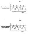
- the procedure of the embodiment detects an engine misfire, based on the rotational fluctuation difference proportions Nja2, Nja3, and Nja4 with regard to the rotational fluctuation difference Nxd360 and the rotational fluctuation difference proportions Njb2, Njb3, and Njb4 with regard to the rotational fluctuation difference Nxd720, in addition to the results of comparison that the rotational fluctuation difference Nxd360 in a certain cylinder exceeds the first 360-degree misfire reference value A1 and that the rotational fluctuation difference Nxd720 in the certain cylinder exceeds the first 720-degree misfire reference value B1.
- the warm-up time engine misfire detection process of this embodiment ensures adequate and accurate detection of an engine misfire during warm-up of the catalyst included in the exhaust emission control unit 134 with a significant delay of the ignition timing in the engine 22.
- the engine misfire detection apparatus of the second embodiment mounted on the hybrid vehicle 20B calculates the four intermediate rotational fluctuation differences Nm(1) through Nm(4) as the differences of the rotational fluctuations Nxd(n-2), Nxd(n-3), Nxd(n-4), and Nxd(n-5) from the rotational fluctuation Nxd(n-1).
- the rotational fluctuation Nxd(n-1) regards the immediate-prior cylinder fired immediately before the certain cylinder, which has the rotational fluctuation Nxd(n) and is expected to be misfired based on the rotational fluctuation difference Nxd360 and the rotational fluctuation difference Nxd720.
Landscapes
- Engineering & Computer Science (AREA)
- Chemical & Material Sciences (AREA)
- Combustion & Propulsion (AREA)
- Mechanical Engineering (AREA)
- General Engineering & Computer Science (AREA)
- Transportation (AREA)
- Automation & Control Theory (AREA)
- Signal Processing (AREA)
- Chemical Kinetics & Catalysis (AREA)
- Theoretical Computer Science (AREA)
- Health & Medical Sciences (AREA)
- Physics & Mathematics (AREA)
- General Physics & Mathematics (AREA)
- General Health & Medical Sciences (AREA)
- Biomedical Technology (AREA)
- Toxicology (AREA)
- Combined Controls Of Internal Combustion Engines (AREA)
- Exhaust Gas After Treatment (AREA)
- Electrical Control Of Ignition Timing (AREA)
- Control Of Vehicle Engines Or Engines For Specific Uses (AREA)
- Testing Of Engines (AREA)
- Hybrid Electric Vehicles (AREA)
Claims (17)
- Maschinenfehlzündungserfassungsgerät (24), das eine Fehlzündung in einer mehrzylindrigen Brennkraftmaschine (22) mit variabler Zündzeitpunktsteuerung erfasst, wobei das Maschinenfehlzündungserfassungsgerät (24) Folgendes aufweist:eine Drehstellungserfassungseinheit (140), die eine Drehstellung einer Kurbelwelle (26) der Brennkraftmaschine (22) erfasst;ein Drehschwankungsberechnungsmodul (24a), das sequenziell Drehschwankungen (Nxd(n)) bei Kurbelwinkeln (CA), die mit jeweiligen Zündzeitpunkten der mehreren Zylinder in der Brennkraftmaschine (22) korrespondieren, auf den erfassten Drehstellungen der Kurbelwelle (26) der Brennkraftmaschine (22) beruhend berechnet;ein Drehschwankungsdifferenzberechnungsmodul (24a), das eine erste Drehschwankungsdifferenz (Nxd360) und eine zweite Drehschwankungsdifferenz (Nxd720) berechnet, wobei die erste Drehschwankungsdifferenz (Nxd360) eine Differenz zwischen jeder der bei den korrespondierenden Kurbelwinkel (CA) sequenziell berechneten Drehschwankungen (Nxd(n)) und einer Drehschwankung (Nxd(n-3)) darstellt, die bei einem Kurbelwinkel berechnet wird, der um einen voreingestellten ersten Winkel vor jedem der korrespondierenden Kurbelwinkel (CA) liegt, und wobei die zweite Drehschwankungsdifferenz (Nxd720) eine Differenz zwischen jeder der bei den korrespondierenden Kurbelwinkel (CA) sequenziell berechneten Drehschwankungen (Nxd(n)) und einer Drehschwankung (Nxd(n-6)) darstellt, die bei einem Kurbelwinkel berechnet wird, der um einen voreingestellten zweiten Winkel, welcher von dem voreingestellten ersten Winkel verschieden ist, vor jedem der korrespondierenden Kurbelwinkel (CA) liegt; undein Maschinenfehlzündungserfassungsmodul (24a), das eine Fehlzündung der Brennkraftmaschine (22) basierend auf der ersten Drehschwankungsdifferenz (Nxd360) und der zweiten Drehschwankungsdifferenz (Nxd720), die durch das Drehschwankungsdifferenzberechnungsmodul (24a) berechnet werden, während einer Zeitdauer von einem Start der Brennkraftmaschine (22) bis zum Erfüllen einer vorbestimmten Bedingung erfasst.
- Maschinenfehlzündungserfassungsgerät (24) nach Anspruch 1, wobei die vorbestimmte Bedingung ein Abschließen des Aufwärmens des Katalysators ist, der in einer Abgassteuereinheit (134) der Brennkraftmaschine (22) enthalten ist.
- Maschinenfehlzündungserfassungsgerät (24) nach Anspruch 1, wobei die Brennkraftmaschine (22) bei einem Start mit einem verzögerten Zündzeitpunkt zum Aufwärmen eines in einer Abgassteuereinheit (134) der Brennkraftmaschine (22) enthaltenen Katalysators betrieben wird.
- Maschinenfehlzündungserfassungsgerät (24) nach Anspruch 1, wobei das Maschinenfehlzündungserfassungsmodul (24a) die Fehlzündung der Brennkraftmaschine (22) dann erfasst, wenn die erste Drehschwankungsdifferenz (Nxd360) nicht weniger als ein voreingestellter erster Wert (A1) ist und wenn die zweite Drehschwankungsdifferenz (Nxd720) nicht weniger als ein voreingestellter zweiter Wert (B1) ist, der von dem voreingestellten ersten Wert (A1) verschieden ist.
- Maschinenfehlzündungserfassungsgerät (24) nach Anspruch 4, wobei der voreingestellte erste Wert (A1) kleiner als der voreingestellte zweite Wert (B1) ist.
- Maschinenfehlzündungserfassungsgerät (24) nach Anspruch 4, wobei das Maschinenfehlzündungserfassungsmodul (24a) die Fehlzündung der Brennkraftmaschine (22) dann erfasst, wenn sich ein Verhältnis (Nja2, Nja3, Nja4) einer ersten Zieldrehschwankungsdifferenz (Nxd360(3)), die als eine erste Drehschwankungsdifferenz (Nxd360) von nicht weniger als dem voreingestellten ersten Wert (A1) ausgewählt ist, zu einer anderen ersten Drehschwankungsdifferenz (Nxd360(0), Nxd360(2), Nxd360(4)), die von der ersten Zieldrehschwankungsdifferenz (Nxd360(3)) verschieden ist, in einem vorbestimmten ersten Fehlzündungsidentifizierungsverhältnisbereich (A21<Nja2<A22, A31<Nja3<A32, A41<Nja4<A42) befindet und wenn sich ein Verhältnis (Njb) einer zweiten Zieldrehschwankungsdifferenz (Nxd720(3)), die als eine zweite Drehschwankungsdifferenz (Nxd720) von nicht weniger als dem voreingestellten zweiten Wert (B1) ausgewählt ist, zu einer anderen zweiten Drehschwankungsdifferenz (Nxd720(0), Nxd720(2), Nxd720(4)), die von der zweiten Zieldrehschwankungsdifferenz (Nxd720(3)) verschieden ist, in einem vorbestimmten zweiten Fehlzündungsidentifizierungsbereich (B21<Njb2<B22, B31<Njb3<B32, B41<Njb4<B42) befindet, der von dem vorbestimmten ersten
Fehlzündungsidentifizierungsverhältnisbereich (A21<Nja2<A22, A31<Nja3<A32, A41<Nja4<A42) ist. - Maschinenfehlzündungserfassungsgerät (24) nach Anspruch 6, wobei
die andere erste Drehschwankungsdifferenz (Nxd360(0), Nxd360(2), Nxd360(4)) eine von einer vorvorletzten ersten Drehschwankungsdifferenz (Nxd360(0)), die an dritter Stelle vor der ersten Zieldrehschwankungsdifferenz (Nxd360(3)) steht, einer unmittelbar letzten ersten Drehschwankungsdifferenz (Nxd360(2)), die an der Stelle unmittelbar vor der ersten Zieldrehschwankungsdifferenz (Nxd360(3)) steht, und einer unmittelbar nachfolgenden ersten Drehschwankungsdifferenz (Nxd360(4)) ist, die an der Stelle unmittelbar nach der ersten Zieldrehschwankungsdifferenz (Nxd360(3)) steht, und
die andere zweite Drehschwankungsdifferenz (Nxd720(0), Nxd720(2), Nxd720(4)) eine von einer vorvorletzten zweiten Drehschwankungsdifferenz (Nxd720(0)), die an dritter Stelle vor der zweiten Zieldrehschwankungsdifferenz steht, einer unmittelbar nachfolgenden zweiten Drehschwankungsdifferenz (Nxd720(2)), die an der Stelle unmittelbar vor der zweiten Zieldrehschwankungsdifferenz (Nxd720(0)) steht, und einer unmittelbar nachfolgenden zweiten Drehschwankungsdifferenz (Nxd720(4)) ist, die an der Stelle unmittelbar nach der zweiten Zieldrehschwankungsdifferenz (Nxd720(0)) steht. - Maschinenfehlzündungserfassungsgerät (24) nach Anspruch 4, wobei
das Maschinenfehlzündungserfassungsmodul (24a) die Fehlzündung der Brennkraftmaschine (22) unter einer Bedingung erfasst, dass eine
Zwischendrehschwankungsdifferenz (Nm (1) bis Nm(4)) dann niedriger als ein voreingestellter Zwischenreferenzwert (C1) ist, wenn die erste Drehschwankungsdifferenz (Nxd360) nicht weniger als der voreingestellte erste Wert (A1) ist und wenn die zweite Drehschwankungsdifferenz (Nxd720) nicht weniger als der voreingestellte zweite Wert (B1) ist,
wobei die Zwischendrehschwankungsdifferenz (Nm(1) bis Nm(4)) eine Differenz zwischen einer Drehschwankung (Nxd(n-1)) bei einem Kurbelwinkel, der um einen Phasenwinkel vor jedem der korrespondierenden Kurbelwinkel liegt, welcher zu einer Phase der mehreren Zylinder korrespondiert, und einer Drehschwankung (Nxd(n-2), Nxd(n-3), Nxd(n-4), und Nxd(n-5)) bei einem Kurbelwinkel darstellt, der durch Multiplikation des Phasenwinkels mit wenigstens einen numerischen Wert, der unter der Anzahl der mehreren Zylindern, der Zahl -1 und der Zahl -2 ausgewählt ist, vor jedem der korrespondierenden Kurbelwinkel liegt. - Maschinenfehlzündungserfassungsgerät (24) nach Anspruch 8, wobei das Maschinenfehlzündungserfassungsmodul die Fehlzündung der Brennkraftmaschine (22) dann erfasst, wenn alle Zwischendrehschwankungsdifferenzen (Nm(1) bis Nm(4)), die als Differenzen von den Drehschwankungen (Nxd(n)) bei den Kurbelwinkeln vor den Multiplikationen des Phasenwinkels mit der Anzahl, der Zahl -1 und der Zahl -2 gegeben sind, niedriger als der voreingestellte Zwischenreferenzwert (C1) sind.
- Maschinenfehlzündungserfassungsgerät (24) nach Anspruch 1, wobei der voreingestellte erste Winkel 360 Grad ist und der voreingestellte zweite Winkel 720 Grad ist.
- Maschinenfehlzündungserfassungsgerät (24) nach Anspruch 1, wobei das Drehschwankungsberechnungsmodul (24a) eine Drehwinkelgeschwindigkeit (N) bei jedem voreingestellten Kurbelwinkel der Kurbelwelle (26) der Brennkraftmaschine (22) berechnet, und dieses die Drehschwankung (Nxd(n)) als eine Differenz zwischen einer Drehwinkelgeschwindigkeit (N(n)) bei einem Zündzeitpunkt eines jeden der mehreren Zylinder der Brennkraftmaschine (22) und einer Drehwinkelgeschwindigkeit (N(n-1)) bei einem vorangehenden Zündzeitpunkt vor dem voreingestellten Kurbelwinkel berechnet.
- Maschinenfehlzündungserfassungsgerät (24) nach Anspruch 1, wobei das Drehschwankungsberechnungsmodul (24a) eine Drehwinkelbeschleunigung in Entsprechung zu einem Zündzeitpunkt eines jeden der mehreren Zylinder der Brennkraftmaschine (22) als die Drehschwankung (Nxd(n)) bei einem dem Zündzeitpunkt entsprechenden Kurbelwinkel berechnet.
- Maschinenfehlzündungserfassungsgerät (24) nach Anspruch 1, wobei die Brennkraftmaschine (22) auf einem Hybridfahrzeug (20; 20B) montiert ist und bei einem Antriebspunkt betrieben wird, der unabhängig von einem Laufzustand des Hybridfahrzeugs (20; 20B) festgesetzt ist.
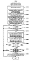
- Maschinenfehlzündungserfassungsverfahren, das eine Fehlzündung in einer mehrzylindrigen Brennkraftmaschine (22) mit variabler Zündzeitpunktsteuerung erfasst, wobei das Maschinenfehlzündungserfassungsverfahren die folgenden Schritte aufweist:(a) sequenzielles Berechnen von Drehschwankungen (Nxd(n)) bei Kurbelwinkeln (CA), die jeweiligen Zündzeitpunkten der mehreren Zylinder in der Brennkraftmaschine (22) entsprechen, basierend auf erfassten Drehstellungen einer Kurbelwelle (26) der Brennkraftmaschine (22) (S120);(b) Berechnen einer ersten Drehschwankungsdifferenz (Nxd360) (S130) und einer zweiten Drehschwankungsdifferenz (Nxd720) (S140), wobei die erste Drehschwankungsdifferenz (Nxd360) eine Differenz zwischen jeder der bei den korrespondierenden Kurbelwinkeln (CA) sequenziell berechneten Drehschwankungen (Nxd(n)) und einer Drehschwankung (Nxd(n-3)) ist, die bei einem Kurbelwinkel berechnet wird, der um einen voreingestellten ersten Winkel vor jedem der korrespondierenden Kurbelwinkel (CA) liegt, und wobei die zweite Drehschwankungsdifferenz (Nxd720) eine Differenz zwischen jeder der bei den korrespondierenden Kurbelwinkeln (CA) sequenziell berechneten Drehschwankungen (Nxd(n)) und einer Drehschwankung (Nxd(n-6)) ist, die bei einem Kurbelwinkel berechnet wird, der um einen voreingestellten zweiten Winkel, der von dem voreingestellten ersten Winkel verschieden ist, vor jedem der korrespondierenden Kurbelwinkel (CA) liegt; und(c) Erfassen einer Fehlzündung der
Brennkraftmaschine (22) basierend auf der berechneten ersten Drehschwankungsdifferenz (Nxd360) und der berechneten zweiten Drehschwankungsdifferenz (Nxd720) während einer Zeitdauer von einem Start der Brennkraftmaschine (22) bis zu einem Erfüllen einer vorbestimmten Bedingung (S150 bis S220). - Maschinenfehlzündungserfassungsverfahren nach Anspruch 14, wobei der Schritt (c) die Fehlzündung der Brennkraftmaschine (22) während der Zeitdauer von dem Start der Brennkraftmaschine (22) bis zum Abschließen des Aufwärmens eines in einer Abgassteuereinheit (134) der Brennkraftmaschine (22) enthaltenen Katalysators erfasst.
- Maschinenfehlzündungserfassungsverfahren nach Anspruch 14, wobei der Schritt (c) die Fehlzündung der Brennkraftmaschine (22) dann erfasst, wenn die erste Drehschwankungsdifferenz nicht weniger als ein voreingestellter erster Wert ist, und dann, wenn die zweite Drehschwankungsdifferenz nicht weniger als ein voreingestellter zweiter Wert ist, der von dem voreingestellten ersten Wert verschieden ist.
- Maschinenfehlzündungserfassungsverfahren nach Anspruch 14, wobei das Maschinenfehlzündungserfassungsverfahren die Fehlzündung der Brennkraftmaschine (22) erfasst, die bei einem Start mit einem verzögerten Zündzeitpunkt zum Aufwärmen eines in einer Abgassteuereinheit (134) der Brennkraftmaschine (22) enthaltenen Katalysators betrieben wird.
Applications Claiming Priority (3)
| Application Number | Priority Date | Filing Date | Title |
|---|---|---|---|
| JP2005048446 | 2005-02-24 | ||
| JP2005259479A JP4525538B2 (ja) | 2005-02-24 | 2005-09-07 | 内燃機関の失火判定装置および失火判定方法 |
| PCT/JP2006/303401 WO2006090829A1 (ja) | 2005-02-24 | 2006-02-24 | 内燃機関の失火判定装置および失火判定方法 |
Publications (3)
| Publication Number | Publication Date |
|---|---|
| EP1852594A1 EP1852594A1 (de) | 2007-11-07 |
| EP1852594A4 EP1852594A4 (de) | 2009-07-22 |
| EP1852594B1 true EP1852594B1 (de) | 2010-12-15 |
Family
ID=36927462
Family Applications (1)
| Application Number | Title | Priority Date | Filing Date |
|---|---|---|---|
| EP06714540A Expired - Lifetime EP1852594B1 (de) | 2005-02-24 | 2006-02-24 | Fehlzündungsbeurteilungsvorrichtung für einen verbrennungsmotor und verfahren zum beurteilen von fehlzündungen |
Country Status (7)
| Country | Link |
|---|---|
| US (1) | US7503208B2 (de) |
| EP (1) | EP1852594B1 (de) |
| JP (1) | JP4525538B2 (de) |
| KR (1) | KR100915178B1 (de) |
| DE (1) | DE602006018870D1 (de) |
| RU (1) | RU2359142C2 (de) |
| WO (1) | WO2006090829A1 (de) |
Families Citing this family (33)
| Publication number | Priority date | Publication date | Assignee | Title |
|---|---|---|---|---|
| JP4552687B2 (ja) * | 2005-01-11 | 2010-09-29 | トヨタ自動車株式会社 | 内燃機関の失火判定装置および失火判定方法 |
| JP4442568B2 (ja) * | 2006-01-27 | 2010-03-31 | トヨタ自動車株式会社 | 内燃機関の失火判定装置および失火判定方法 |
| JP4492549B2 (ja) * | 2006-01-27 | 2010-06-30 | トヨタ自動車株式会社 | 失火判定装置、ハイブリッド自動車及び失火判定方法 |
| JP4702169B2 (ja) * | 2006-05-09 | 2011-06-15 | トヨタ自動車株式会社 | 内燃機関装置およびこれを搭載する車両並びに内燃機関の失火判定方法 |
| JP4007401B1 (ja) * | 2006-07-31 | 2007-11-14 | トヨタ自動車株式会社 | 内燃機関の失火判定装置および失火判定方法 |
| JP4345847B2 (ja) * | 2006-09-01 | 2009-10-14 | トヨタ自動車株式会社 | 内燃機関の失火判定装置および失火判定方法並びに車両 |
| JP4458105B2 (ja) | 2007-03-07 | 2010-04-28 | トヨタ自動車株式会社 | 内燃機関装置およびこれを搭載する車両並びに内燃機関の失火判定方法 |
| JP4321615B2 (ja) | 2007-03-28 | 2009-08-26 | トヨタ自動車株式会社 | 内燃機関装置およびその制御方法並びに内燃機関装置を搭載する車両 |
| JP4276685B2 (ja) * | 2007-07-25 | 2009-06-10 | 株式会社日本自動車部品総合研究所 | 内燃機関の異常検出装置および異常検出方法 |
| JP4483927B2 (ja) * | 2007-10-26 | 2010-06-16 | トヨタ自動車株式会社 | 多気筒内燃機関の失火気筒特定装置 |
| JP2009121303A (ja) * | 2007-11-14 | 2009-06-04 | Denso Corp | 内燃機関の失火検出装置 |
| US7707874B2 (en) * | 2007-12-11 | 2010-05-04 | Toyota Jidosha Kabushiki Kaisha | Misfire determination device and method for internal combustion engine, and vehicle including misfire determination device |
| JP4438858B2 (ja) * | 2007-12-12 | 2010-03-24 | トヨタ自動車株式会社 | 内燃機関の失火判定装置および車両並びにねじれ要素の剛性推定装置,内燃機関の失火判定方法,ねじれ要素の剛性推定方法 |
| JP4691142B2 (ja) * | 2008-07-17 | 2011-06-01 | 本田技研工業株式会社 | 内燃機関の失火検出装置 |
| DE102008041108A1 (de) * | 2008-08-07 | 2010-02-11 | Robert Bosch Gmbh | Verfahren und Vorrichtung zur Erkennung eines laufenden Verbrennungsmotors bei einem Hybridfahrzeug |
| DE102008041453A1 (de) * | 2008-08-22 | 2010-02-25 | Robert Bosch Gmbh | Verfahren zum Betreiben einer Hybridantriebsvorrichtung, Hybridantriebsvorrichtung und elektronisches Steuergerät |
| JP5332791B2 (ja) * | 2009-03-24 | 2013-11-06 | トヨタ自動車株式会社 | ハイブリッド車および内燃機関の失火判定方法 |
| CN102667122B (zh) * | 2010-01-13 | 2015-04-29 | 本田技研工业株式会社 | 内燃机的失火检测装置 |
| GB2480495B (en) * | 2010-05-21 | 2017-08-23 | Gm Global Tech Operations Llc | Method for the detection of a component malfunction along the life of an internal combustion engine |
| JP5488286B2 (ja) * | 2010-07-15 | 2014-05-14 | トヨタ自動車株式会社 | 内燃機関の燃焼状態検出システム |
| JP5450311B2 (ja) * | 2010-08-04 | 2014-03-26 | 日立オートモティブシステムズ株式会社 | アイドルストップ制御方法および制御装置 |
| JP5844162B2 (ja) | 2011-03-09 | 2016-01-13 | 本田技研工業株式会社 | 内燃機関の失火検出装置 |
| JP5402982B2 (ja) * | 2011-05-12 | 2014-01-29 | トヨタ自動車株式会社 | 内燃機関の異常判定装置 |
| JP6001503B2 (ja) | 2013-05-31 | 2016-10-05 | 株式会社日本自動車部品総合研究所 | 内燃機関の失火検出装置 |
| JP6032136B2 (ja) * | 2013-06-05 | 2016-11-24 | トヨタ自動車株式会社 | 内燃機関の失火検出システム |
| CN204610119U (zh) * | 2015-03-12 | 2015-09-02 | 浙江吉利控股集团有限公司 | 用于串联式混合动力车辆的点火系统 |
| JP6407396B1 (ja) * | 2017-12-07 | 2018-10-17 | 三菱電機株式会社 | 内燃機関の制御装置及び制御方法 |
| JP6624324B1 (ja) | 2019-03-29 | 2019-12-25 | トヨタ自動車株式会社 | 内燃機関の失火検出装置、内燃機関の失火検出システム、データ解析装置、内燃機関の制御装置、内燃機関の失火検出方法、および受信実行装置 |
| JP6624325B1 (ja) * | 2019-03-29 | 2019-12-25 | トヨタ自動車株式会社 | 内燃機関の失火検出装置、内燃機関の失火検出システム、データ解析装置、内燃機関の制御装置、内燃機関の失火検出方法、および受信実行装置 |
| JP7431512B2 (ja) * | 2019-05-23 | 2024-02-15 | 日立Astemo株式会社 | 内燃機関制御装置 |
| JP7322852B2 (ja) | 2020-10-09 | 2023-08-08 | トヨタ自動車株式会社 | 内燃機関の失火検出装置 |
| JP7327346B2 (ja) * | 2020-10-16 | 2023-08-16 | トヨタ自動車株式会社 | 内燃機関の制御装置 |
| JP7392672B2 (ja) * | 2021-01-29 | 2023-12-06 | トヨタ自動車株式会社 | 内燃機関の失火検出装置 |
Family Cites Families (16)
| Publication number | Priority date | Publication date | Assignee | Title |
|---|---|---|---|---|
| SU714269A1 (ru) * | 1977-03-15 | 1980-02-05 | Предприятие П/Я В-2504 | Способ вибрационной диагностики динамической нагруженности элементов машин в рабочих услови х |
| JPH04311651A (ja) * | 1991-04-10 | 1992-11-04 | Daihatsu Motor Co Ltd | 内燃機関の失火検出方法 |
| JP2636565B2 (ja) | 1991-07-12 | 1997-07-30 | トヨタ自動車株式会社 | 異常検出装置 |
| JP3351049B2 (ja) * | 1992-11-17 | 2002-11-25 | 株式会社デンソー | 内燃機関の失火検出装置 |
| US5539644A (en) | 1992-11-17 | 1996-07-23 | Nippondenso Co., Ltd. | System for detecting misfire in a multi-cylinder internal combustion engine |
| DE19641610A1 (de) * | 1995-10-09 | 1997-04-10 | Denso Corp | Fehlzündungsdetektor |
| JP3675049B2 (ja) | 1996-08-09 | 2005-07-27 | 株式会社デンソー | 内燃機関の失火検出装置 |
| JP3360566B2 (ja) * | 1997-05-23 | 2002-12-24 | トヨタ自動車株式会社 | 多気筒内燃機関の失火検出装置 |
| JP3643250B2 (ja) | 1999-01-08 | 2005-04-27 | 愛三工業株式会社 | エンジンの失火検出装置 |
| JP3961745B2 (ja) * | 2000-06-22 | 2007-08-22 | 株式会社デンソー | 内燃機関の失火検出装置 |
| JP2002138898A (ja) * | 2000-11-01 | 2002-05-17 | Honda Motor Co Ltd | エンジンの動弁機構 |
| JP2002138893A (ja) * | 2000-11-01 | 2002-05-17 | Denso Corp | 内燃機関の燃焼状態検出装置 |
| DE10231951A1 (de) * | 2001-07-16 | 2003-04-24 | Denso Corp | Steuervorrichtung für eine Verbrennungskraftmaschine |
| JP2003214308A (ja) * | 2002-01-28 | 2003-07-30 | Toyota Motor Corp | ハイブリッド車の点火時期制御装置 |
| JP4552687B2 (ja) * | 2005-01-11 | 2010-09-29 | トヨタ自動車株式会社 | 内燃機関の失火判定装置および失火判定方法 |
| JP4509986B2 (ja) * | 2005-12-27 | 2010-07-21 | 本田技研工業株式会社 | 内燃機関の失火検出装置 |
-
2005
- 2005-09-07 JP JP2005259479A patent/JP4525538B2/ja not_active Expired - Lifetime
-
2006
- 2006-02-24 US US11/666,994 patent/US7503208B2/en active Active
- 2006-02-24 WO PCT/JP2006/303401 patent/WO2006090829A1/ja not_active Ceased
- 2006-02-24 DE DE602006018870T patent/DE602006018870D1/de not_active Expired - Lifetime
- 2006-02-24 KR KR1020077019328A patent/KR100915178B1/ko not_active Expired - Lifetime
- 2006-02-24 RU RU2007132011/06A patent/RU2359142C2/ru active
- 2006-02-24 EP EP06714540A patent/EP1852594B1/de not_active Expired - Lifetime
Also Published As
| Publication number | Publication date |
|---|---|
| US20080148835A1 (en) | 2008-06-26 |
| EP1852594A4 (de) | 2009-07-22 |
| DE602006018870D1 (de) | 2011-01-27 |
| US7503208B2 (en) | 2009-03-17 |
| KR20070111499A (ko) | 2007-11-21 |
| JP2006266253A (ja) | 2006-10-05 |
| JP4525538B2 (ja) | 2010-08-18 |
| RU2359142C2 (ru) | 2009-06-20 |
| EP1852594A1 (de) | 2007-11-07 |
| KR100915178B1 (ko) | 2009-09-03 |
| RU2007132011A (ru) | 2009-02-27 |
| WO2006090829A1 (ja) | 2006-08-31 |
Similar Documents
| Publication | Publication Date | Title |
|---|---|---|
| US7503208B2 (en) | Engine misfire detection apparatus for internal combustion engine and engine misfire detection method | |
| US7503207B2 (en) | Engine misfire identification device for internal combustion engine and engine misfire identification method | |
| AU2006336750B2 (en) | Misfire judging apparatus, and method of misfire judgment, for internal combustion engine | |
| EP2017453B1 (de) | Verbrennungsmotorvorrichtung und verfahren zur beurteilung von fehlzündungen für einen verbrennungsmotor | |
| US7971474B2 (en) | Internal combustion engine system and engine misfire detection method for internal combustion engine | |
| EP2123891A1 (de) | Verbrennungsmotor und damit versehenes fahrzeug sowie verfahren zur beurteilung der fehlzündung eines verbrennungsmotors | |
| US20040011311A1 (en) | Valve timing control apparatus for internal combustion engine | |
| CN106150731A (zh) | 发动机装置 | |
| US20170268453A1 (en) | Vehicle and control method for vehicle | |
| JP4894935B2 (ja) | 内燃機関の失火判定装置および失火判定方法 | |
| CN100585151C (zh) | 内燃机的失火判定装置以及失火判定方法 | |
| JP2006233800A (ja) | 内燃機関の失火判定装置および失火判定方法 | |
| EP2011980A1 (de) | Verbrennungsmotor, damit ausgestattetes fahrzeug und verfahren zur steuerung eines verbrennungsmotors | |
| JP2006194125A (ja) | 内燃機関の失火判定装置および失火判定方法 | |
| JP2010203296A (ja) | 内燃機関装置およびこれを搭載する車両並びに内燃機関の制御方法 |
Legal Events
| Date | Code | Title | Description |
|---|---|---|---|
| PUAI | Public reference made under article 153(3) epc to a published international application that has entered the european phase |
Free format text: ORIGINAL CODE: 0009012 |
|
| 17P | Request for examination filed |
Effective date: 20070516 |
|
| AK | Designated contracting states |
Kind code of ref document: A1 Designated state(s): DE FR GB |
|
| DAX | Request for extension of the european patent (deleted) | ||
| RBV | Designated contracting states (corrected) |
Designated state(s): DE FR GB |
|
| A4 | Supplementary search report drawn up and despatched |
Effective date: 20090624 |
|
| RIC1 | Information provided on ipc code assigned before grant |
Ipc: F02D 45/00 20060101AFI20070525BHEP Ipc: F01N 3/20 20060101ALI20090618BHEP Ipc: B60W 10/06 20060101ALI20090618BHEP Ipc: F02D 41/14 20060101ALI20090618BHEP Ipc: B60W 20/00 20060101ALI20090618BHEP Ipc: F02P 5/15 20060101ALI20090618BHEP |
|
| GRAP | Despatch of communication of intention to grant a patent |
Free format text: ORIGINAL CODE: EPIDOSNIGR1 |
|
| GRAS | Grant fee paid |
Free format text: ORIGINAL CODE: EPIDOSNIGR3 |
|
| GRAA | (expected) grant |
Free format text: ORIGINAL CODE: 0009210 |
|
| AK | Designated contracting states |
Kind code of ref document: B1 Designated state(s): DE FR GB |
|
| REG | Reference to a national code |
Ref country code: GB Ref legal event code: FG4D |
|
| REF | Corresponds to: |
Ref document number: 602006018870 Country of ref document: DE Date of ref document: 20110127 Kind code of ref document: P |
|
| PLBE | No opposition filed within time limit |
Free format text: ORIGINAL CODE: 0009261 |
|
| STAA | Information on the status of an ep patent application or granted ep patent |
Free format text: STATUS: NO OPPOSITION FILED WITHIN TIME LIMIT |
|
| 26N | No opposition filed |
Effective date: 20110916 |
|
| REG | Reference to a national code |
Ref country code: DE Ref legal event code: R097 Ref document number: 602006018870 Country of ref document: DE Effective date: 20110916 |
|
| REG | Reference to a national code |
Ref country code: GB Ref legal event code: 746 Effective date: 20121112 |
|
| REG | Reference to a national code |
Ref country code: DE Ref legal event code: R084 Ref document number: 602006018870 Country of ref document: DE Effective date: 20121115 |
|
| REG | Reference to a national code |
Ref country code: FR Ref legal event code: PLFP Year of fee payment: 11 |
|
| REG | Reference to a national code |
Ref country code: FR Ref legal event code: PLFP Year of fee payment: 12 |
|
| REG | Reference to a national code |
Ref country code: FR Ref legal event code: PLFP Year of fee payment: 13 |
|
| P01 | Opt-out of the competence of the unified patent court (upc) registered |
Effective date: 20230517 |
|
| PGFP | Annual fee paid to national office [announced via postgrant information from national office to epo] |
Ref country code: FR Payment date: 20241231 Year of fee payment: 20 |
|
| PGFP | Annual fee paid to national office [announced via postgrant information from national office to epo] |
Ref country code: DE Payment date: 20241231 Year of fee payment: 20 |
|
| PGFP | Annual fee paid to national office [announced via postgrant information from national office to epo] |
Ref country code: GB Payment date: 20250102 Year of fee payment: 20 |
|
| REG | Reference to a national code |
Ref country code: DE Ref legal event code: R071 Ref document number: 602006018870 Country of ref document: DE |
|
| REG | Reference to a national code |
Ref country code: GB Ref legal event code: PE20 Expiry date: 20260223 |