EP1850165A1 - Système de source lumineuse, lecteur optique, appareil de formation d'images, procédé de contrôle de la quantité de lumière, procédé de lecture optique et procédé de formation d'images - Google Patents
Système de source lumineuse, lecteur optique, appareil de formation d'images, procédé de contrôle de la quantité de lumière, procédé de lecture optique et procédé de formation d'images Download PDFInfo
- Publication number
- EP1850165A1 EP1850165A1 EP07106285A EP07106285A EP1850165A1 EP 1850165 A1 EP1850165 A1 EP 1850165A1 EP 07106285 A EP07106285 A EP 07106285A EP 07106285 A EP07106285 A EP 07106285A EP 1850165 A1 EP1850165 A1 EP 1850165A1
- Authority
- EP
- European Patent Office
- Prior art keywords
- light
- optical
- light source
- light beams
- splitter
- Prior art date
- Legal status (The legal status is an assumption and is not a legal conclusion. Google has not performed a legal analysis and makes no representation as to the accuracy of the status listed.)
- Granted
Links
- 230000003287 optical effect Effects 0.000 title claims abstract description 266
- 238000000034 method Methods 0.000 title claims description 31
- 238000011144 upstream manufacturing Methods 0.000 claims description 7
- 238000007493 shaping process Methods 0.000 claims description 5
- 230000009467 reduction Effects 0.000 description 28
- 238000004519 manufacturing process Methods 0.000 description 26
- 230000008878 coupling Effects 0.000 description 23
- 238000010168 coupling process Methods 0.000 description 23
- 238000005859 coupling reaction Methods 0.000 description 23
- 230000001965 increasing effect Effects 0.000 description 18
- 230000006870 function Effects 0.000 description 15
- 238000001514 detection method Methods 0.000 description 14
- 238000009826 distribution Methods 0.000 description 13
- 230000007613 environmental effect Effects 0.000 description 10
- 239000004065 semiconductor Substances 0.000 description 10
- 230000004048 modification Effects 0.000 description 9
- 238000012986 modification Methods 0.000 description 9
- 239000011347 resin Substances 0.000 description 8
- 229920005989 resin Polymers 0.000 description 8
- 238000005516 engineering process Methods 0.000 description 7
- 239000011248 coating agent Substances 0.000 description 6
- 238000000576 coating method Methods 0.000 description 6
- 239000011521 glass Substances 0.000 description 6
- 230000015556 catabolic process Effects 0.000 description 5
- 238000006731 degradation reaction Methods 0.000 description 5
- 230000000694 effects Effects 0.000 description 5
- 229910052782 aluminium Inorganic materials 0.000 description 3
- XAGFODPZIPBFFR-UHFFFAOYSA-N aluminium Chemical group [Al] XAGFODPZIPBFFR-UHFFFAOYSA-N 0.000 description 3
- 239000003086 colorant Substances 0.000 description 3
- 229910052751 metal Inorganic materials 0.000 description 3
- 239000002184 metal Substances 0.000 description 3
- 238000002310 reflectometry Methods 0.000 description 3
- 239000000758 substrate Substances 0.000 description 3
- 238000012546 transfer Methods 0.000 description 3
- 238000004364 calculation method Methods 0.000 description 2
- 230000001419 dependent effect Effects 0.000 description 2
- 239000004973 liquid crystal related substance Substances 0.000 description 2
- 238000003754 machining Methods 0.000 description 2
- 230000007246 mechanism Effects 0.000 description 2
- 230000008569 process Effects 0.000 description 2
- 238000002834 transmittance Methods 0.000 description 2
- 238000004140 cleaning Methods 0.000 description 1
- 238000004590 computer program Methods 0.000 description 1
- 238000010276 construction Methods 0.000 description 1
- 230000003247 decreasing effect Effects 0.000 description 1
- 238000011161 development Methods 0.000 description 1
- 238000010586 diagram Methods 0.000 description 1
- 230000002708 enhancing effect Effects 0.000 description 1
- 230000002349 favourable effect Effects 0.000 description 1
- 238000009434 installation Methods 0.000 description 1
- 239000000463 material Substances 0.000 description 1
- 239000013307 optical fiber Substances 0.000 description 1
- 230000002093 peripheral effect Effects 0.000 description 1
- 238000012545 processing Methods 0.000 description 1
- 238000003672 processing method Methods 0.000 description 1
- 230000004044 response Effects 0.000 description 1
- 238000007740 vapor deposition Methods 0.000 description 1
Images


Classifications
-
- G—PHYSICS
- G02—OPTICS
- G02B—OPTICAL ELEMENTS, SYSTEMS OR APPARATUS
- G02B26/00—Optical devices or arrangements for the control of light using movable or deformable optical elements
- G02B26/08—Optical devices or arrangements for the control of light using movable or deformable optical elements for controlling the direction of light
- G02B26/10—Scanning systems
- G02B26/12—Scanning systems using multifaceted mirrors
- G02B26/124—Details of the optical system between the light source and the polygonal mirror
-
- G—PHYSICS
- G02—OPTICS
- G02B—OPTICAL ELEMENTS, SYSTEMS OR APPARATUS
- G02B19/00—Condensers, e.g. light collectors or similar non-imaging optics
- G02B19/0004—Condensers, e.g. light collectors or similar non-imaging optics characterised by the optical means employed
- G02B19/0009—Condensers, e.g. light collectors or similar non-imaging optics characterised by the optical means employed having refractive surfaces only
- G02B19/0014—Condensers, e.g. light collectors or similar non-imaging optics characterised by the optical means employed having refractive surfaces only at least one surface having optical power
-
- G—PHYSICS
- G02—OPTICS
- G02B—OPTICAL ELEMENTS, SYSTEMS OR APPARATUS
- G02B19/00—Condensers, e.g. light collectors or similar non-imaging optics
- G02B19/0033—Condensers, e.g. light collectors or similar non-imaging optics characterised by the use
- G02B19/0047—Condensers, e.g. light collectors or similar non-imaging optics characterised by the use for use with a light source
- G02B19/0052—Condensers, e.g. light collectors or similar non-imaging optics characterised by the use for use with a light source the light source comprising a laser diode
- G02B19/0057—Condensers, e.g. light collectors or similar non-imaging optics characterised by the use for use with a light source the light source comprising a laser diode in the form of a laser diode array, e.g. laser diode bar
-
- G—PHYSICS
- G02—OPTICS
- G02B—OPTICAL ELEMENTS, SYSTEMS OR APPARATUS
- G02B19/00—Condensers, e.g. light collectors or similar non-imaging optics
- G02B19/0033—Condensers, e.g. light collectors or similar non-imaging optics characterised by the use
- G02B19/0047—Condensers, e.g. light collectors or similar non-imaging optics characterised by the use for use with a light source
- G02B19/0061—Condensers, e.g. light collectors or similar non-imaging optics characterised by the use for use with a light source the light source comprising a LED
-
- G—PHYSICS
- G02—OPTICS
- G02B—OPTICAL ELEMENTS, SYSTEMS OR APPARATUS
- G02B27/00—Optical systems or apparatus not provided for by any of the groups G02B1/00 - G02B26/00, G02B30/00
- G02B27/09—Beam shaping, e.g. changing the cross-sectional area, not otherwise provided for
- G02B27/0938—Using specific optical elements
- G02B27/0988—Diaphragms, spatial filters, masks for removing or filtering a part of the beam
Definitions
- the present invention relates to a light source system, an optical scanner, an image forming apparatus, a light-amount control method, an optical scanning method, and an image forming method.
- a raster output scanner having a light source such as a surface-emitting laser to emit a number of light beams has been proposed.
- a light source such as a surface-emitting laser to emit a number of light beams.
- Japanese Patent Application Laid-open No. H10-100476 discloses a raster scanner that uses a semitransparent and semi-reflecting member as a photo-detector to reflect light emitted from the light source.
- Japanese Patent Application Laid-open No. 2002-26445 discloses a light source device of a type using a surface-emitting semiconductor laser, having a light-receiving surface placed on a substrate of the semiconductor laser.
- the device detects an amount of emitted light with a splitter that splits a traveling path of light beams emitted from the semiconductor laser into a plurality of paths so that the light beams pass through the light-receiving surface.
- Japanese Patent Application Laid-open No. 2005-274678 discloses an optical scanner having a plurality of light emitting points, an optical unit that collimates light beams, and a beam reflecting member that transmits a portion of the light beams therethrough and reflects another portion of the light beams therefrom.
- the optical scanner detects a light amount pertaining to even a light source that has no back beams.
- a unit that detects the light amount and the light source are disposed on a single base member to miniaturize the optical scanner.
- Japanese Patent Application Laid-open No. H06-164070 discloses a light source device provided with an aperture for shaping light beams emitted from a semiconductor laser having a plurality of linearly-aligned light emitting sources, and a plurality of light receiving elements corresponding to the light emitting sources, which receive detecting light beams reflected from a mirror surface provided on the aperture.
- Japanese Patent No. 3227226 discloses a technology related to a positional relationship between a scanning line provided by a surface emitting laser and an image-forming spot to thereby attain high-speed scanning.
- Optical scanners particularly laser scanners employing a semiconductor laser are advantageous in simple structure, high speed performance, and high resolution, and are therefore in wide use as image forming apparatuses, such as an image display apparatus and an image recording apparatus.
- the optical scanner is suitably used for an exposure device of an electrophotographic printer, and many products are currently on the market as laser printers.
- Japanese Patent No. 3227226 proposes an image forming apparatus that uses a so-called multi-beam scanner.
- the scanner scans with light beams emitted from a vertical cavity surface emitting laser (VCSEL) having a plurality of independently-controllable light emitting points, and performs scanning with a plurality of scanning lines simultaneously in a single scanning operation.
- VCSEL vertical cavity surface emitting laser
- Fig. 1 is an example of a conventional optical scanner using a VCSEL having such a plurality of light emitting areas.
- a light source 101 has a plurality of light emitting areas and a light emission controller for controlling the light emitting areas.
- a plurality of laser beams are emitted from the light source 101, and coupled to be shaped through a coupling optical unit formed with a coupling lens 102 and a cylindrical lens 103.
- the thus-coupled beams are deflectively reflected from a deflector 105, which is a rotary polygon mirror, and subjected to scanning in a main scanning direction.
- the beams forms a scanning line 109 on a scanning surface (photosensitive member) 108, which is an image surface, through an image-forming optical unit formed with a first scanning lens (106a) and a second scanning lens (106b).
- a cylindrical image carrier supporting a photosensitive medium is used as the scanning surface 108.
- the image carrier rotates about an axis of the cylinder shown in Fig. 1 to move the image surface in the direction perpendicular to the main scanning direction, thereby performing optical scanning to form an image.
- H10-100476 , 2002-26445 , and 2005-274678 describes a light source or an optical scanner using a VCSEL, which detects a light intensity of each light beam with a light receiving surface and controls light emitting devices with a control circuit based on data on the detected value to attain a desired optical intensity.
- the laser is required to have an increased output power in addition to adopting the multi-beam method.
- the reason for this requirement is as follows.
- an exposure energy exceeding a required amount per unit area and unit time must be provided on a photosensitive member, which functions as the scanning surface. Accordingly, a greater optical power or an increase in efficiency for light utilization is required to increase a linear velocity (moving speed of the surface of the photosensitive member) of the photosensitive member to thereby achieve a higher speed.
- VCSEL elements While attempts to increase an optical power have been made through development of VCSEL elements, a ratio of the increase achieved so far is small.
- Japanese Patent Application Laid-open Nos. H10-100476 , 2002-26445 , 2005-274678 , and H06-164070 do not or hardly suggest enhancement of efficiency for light utilization.
- a light receiving surface for detecting the light amount is mounted in a light source apparatus.
- the optical path between the light source and the light receiving surface is reduced in length, which allows highly accurate detection of the light amount and image forming of high quality.
- a triangular prism or the like employed as the splitter produces a great loss of light in supplying light to the outside.
- Increasing the optical output power is the currently imposed requirement on the surface emitting laser.
- a solution for the requirement has not been disclosed yet.
- optical scanning and image forming are carried out using a portion of light beams having passed through a beam returning member. Therefore, when a surface emitting laser, of which optical output power are to be increased, is employed as the light source, a loss in light amount exceeds a negligible amount and hence poses a problem to increase the speed.
- a light source system with at least one light source controls an amount of light from the light source, and includes a detector that detects light intensity of a first light bundle emitted from the light source, a splitter that splits the first light bundle into at least a second light bundle and a third light bundle such that a light component near a peak of the light intensity in a plane perpendicular to a propagation direction of the first light bundle is included only in the third light bundle, and an optical detecting system that guides the second light bundle to the detector.
- a light-amount control method for controlling an amount of light from at least one light source includes detecting, by a detector, light intensity of a first light bundle emitted from the light source, splitting the first light bundle into at least a second light bundle and a third light bundle such that a light component near a peak of the light intensity in a plane perpendicular to a propagation direction of the first light bundle is included only in the third light bundle, and guiding the second light bundle to the detector.
- a light source system is capable of controlling a light amount by detecting light intensities of a plurality of light beams F0 emitted from at least one light source with a common detector.
- the system includes a splitter that splits the light beams F0 into at least light beams FM and light beams FS; and an optical detecting unit that guides the light beams FM to the detector.
- Light components near a light-intensity peak point of the light beams F0 on a cross section perpendicular to a propagation direction of the light beams F0 are included only in the light beams FS rather than in the light beams FM.
- the light beams have a substantially circular or elliptic cross section with its intensity peak near the center.
- Light in the peak portion is supplied to the outside, and light in the remaining portion is detected for control of a light amount. This enables control of the light amount and efficient supply of light to the outside. Efficiency for light utilization is thus increased, and energy saving and reduction of environmental load are attained.
- the light source system that allows a light amount to be adjusted to a desired value appropriately and supply light of a sufficient amount to the outside is provided.
- the light source system can further include driving circuitry a portion of which is formed integrally with the detector.
- the driving circuitry drives the light source.
- a light receiving element or the like which functions as the detector, and the light source are supported on a single substrate or a single base member. Therefore, a necessary footprint can be reduced as compared with a configuration in which the detector and the light source are independently formed, and hence miniaturization of the system and an apparatus using the system are attained.
- a wiring board, a support member, and the like can be used partially in a shared manner. This reduces the number of components and thereby reduces cost and environmental load.
- the system and the apparatus are miniaturized, enhanced in stability of light amount control against external noise, and reduced in the number of components and cost.
- the light source system can include a light reflecting member as the splitter.
- a light reflecting member such as a mirror as the splitter allows light to be supplied to the detector and/or to the outside highly efficiently with low loss.
- the system can be miniaturized because an optical path can be bent using a mirror.
- the light can be detected highly efficiently and supplied at high output power. This leads to miniaturization of the system.
- the light source system can include a curved mirror having a positive focal power as the splitter.
- This configuration allows the splitter to converge light on the detector to thereby function also as the optical detecting unit. This eliminates the need of forming the optical detecting unit with another component, and reduces the number of components. The reduction in the number of components also reduces the footprint for devices, and hence miniaturizes the apparatus.
- the light source system can include a light transmitting member as the splitter.
- a positional deviation of a beam spot can be reduced because light beams are insusceptible to a surface shape of the element in contrast to a surface shape of a reflecting optical element such as a mirror.
- miniaturization of the light receiving element is attained.
- having a sufficient allowance in accuracy of the surface shape improves a yield rate and reduces the cost of the system.
- the light source system can include an optical element having a focal length that reaches a point between the light source and the splitter.
- the splitter is positioned near a rear focal point of the optical element in an optical axis direction of the optical element.
- cross sections of out-of-optical-axis light beams that do not intersect an optical axis of an optical system such as a lens and therefore are at different distances from the optical axis generally do not spatially coincide with one another.
- portions corresponding to different areas in light intensity distribution are subjected to detection. Consequently, the light beams undesirably differ from one another in light amount.
- even chief rays of light beams out of the optical axis intersect with the optical axis, which allows intensity centers of the light beams to align.
- a ratio of a split light amount to a total light amount for each light beam becomes uniform through the light beams.
- a light amount controls can be performed uniformly on the plurality of light beams.
- the light beams are substantially identical in ratio, which is a ratio of a portion of light that reaches the detector to the light. Hence, each light beam is allowed to have a highly-accurately uniform amount of light on the detector.
- the light source system can include a VCSEL as the light source.
- the VCSEL when the VCSEL is used, in contrast to an LD array that uses a plurality of edge-emitting semiconductor laser diodes, as the number of light beams to be emitted increases, the cost is reduced by a greater amount. Meanwhile, the VCSEL has a considerably short cavity length and therefore has a smaller mode hopping than that of the LD array. This reduces degradation in optical scanning quality due to variations in wavelength.
- An optical scanner includes the light source system as described above; a beam shaper that shapes the plurality of light source system emitted from the light source system; a deflector that deflects the shaped light beams for scanning in a main scanning direction; and a optical scanning unit that causes the light beams deflected for scanning to form an image on a scanning surface.
- the beam shaper has an aperture member through which the light beams FS originated from the light source are shaped.
- the optical scanner that allows to increase the efficiency for light utilization, reduce light amount requirement, and, even when a low-output light source is used, detect a light amount as well as perform optical scanning with a sufficient light amount is provided.
- the optical scanner can includes the splitter that is arranged such that the light beams FS and the light beams FM form an angle only in a plane substantially perpendicular to a direction along which a smaller one of a main-scanning direction width and a sub-scanning direction width of an opening in the aperture member extends.
- vignetting of a miniscule number of light beams undesirably occurs at edges of the opening; that is, at a boundary between a light-beam passing portion and a light-beam intercepting portion, due to a limit in machining accuracy.
- the influence of this vignetting is considerably small because a typical aperture member is arranged perpendicular to a traveling direction of the light beams.
- a member such as in the splitter and/or the aperture member of the embodiment, that is arranged obliquely to the traveling direction of the light beams rather than perpendicularly is included, vignetting of light beams occurs depending on the thickness of the member.
- the amount of the light beams subjected to vignetting increases, and the apparatus becomes more susceptible to a dimensional error and a positional error that have occurred during manufacturing.
- the larger the opening width the less influence the vignetting exerts in terms of a ratio.
- beam-spot diameter variations on an image surface that are dependent on the opening can be reduced.
- the splitter and/or the aperture member is desirably disposed to be rotated about its rotary axis perpendicular to a direction along which longer widths of the opening extend.
- an optical image-forming system that includes the optical scanning unit and the light source system are housed in an optical housing to form the optical scanner.
- a lid of the optical housing is substantially parallel with a main scanning plane.
- an optical element disposed in the optical housing such that the light beams FS and FM in the light source system are substantially collimated with the main scanning plane is facilitated to receive arrangement and adjustment works in a state with the lid of the optical housing removed.
- a reduction in a manufacturing yield rate is prevented, which increases a manufacturing speed.
- positional adjustment of components such as the light receiving element and the optical element; e.g., the splitter is facilitated.
- reduction of the thickness of the entire optical housing in the sub-scanning direction is attained, which allows miniaturization of the optical scanner.
- the optical scanner can include the splitter that performs splitting such that the light beams FM and the light beams FS form an angle in a plane parallel to a sub-scanning plane that is perpendicular to a main scanning plane.
- the interference can be avoided by distributing light beams in the sub-scanning direction.
- a stray light is generated by any one of the optical elements in the light source system, it is possible to cause the stray light to less easily reach the scanning surface.
- light reflected from a surface of a lens that converges light to the light receiving element has an angle in the sub-scanning direction. Therefore, the reflected light does not reach a light deflector (e.g., polygon mirror).
- a light deflector e.g., polygon mirror
- the optical scanner is miniaturized by increasing layout flexibility of the light source system.
- a reflected, scattered, diffracted component of the light beams FM in the light source system enters the optical scanning unit as the stray light and reaches the scanning surface, thereby preventing ghost.
- the optical scanner can include the aperture member and the splitter that are integrally formed.
- the member functioning as the aperture member is processed to have the function as the splitter, thereby integrating the two functions into the single member to reduce cost. This also reduces the footprint and hence miniaturizes the apparatus.
- the optical scanner can include the aperture member and the splitter, which are separate members, in the traveling direction of the light beams.
- the splitter is disposed upstream from the aperture member.
- the aperture member and the splitter are configured as separate members, which facilitates manufacturing of them, and hence increases a manufacturing yield rate.
- disposing the splitter upstream from the aperture member to be closer to the light source shortens the optical path from the light source to the detector. This leads to miniaturization of the apparatus, and, even when the apparatus has a manufacturing error, deviation of the beam spot on the detector can be reduced.
- the apparatus is miniaturized and facilitated in manufacturing of the components.
- the optical scanner can include the splitter clips, from of the light beams F0, a portion that passes through the opening in the aperture member as the light beams FS, and a portion that surrounds the light beams FS as the light beams FM.
- This configuration allows a greater number of light beams to be guided, among light beams that are intercepted by the aperture member and cannot be utilized in optical scanning, to the detector. Hence, the efficiency for light utilization is increased and thereby an S/N ratio at detection is increased. Accordingly, the light amount can be controlled at high accuracy, which enables excellent optical scanning.
- the optical scanner capable of detecting the light amount at a high efficiency for light utilization, increasing the S/N ratio in detection, and excellently controlling the light amount is provided.
- the optical scanner can include the splitter that is adjacent to the opening in the aperture member at only one side perpendicular to the sub-scanning direction.
- the splitter can have an easily-manufacturable shape.
- the number of the splitters can be reduced, which allows cost reduction.
- the structure of the splitter is simplified, and manufacturing of the splitter is facilitated.
- the optical scanner can include a VCSEL as the light source.
- the VCSEL when the VCSEL is used, in contrast to an LD array that uses a plurality of edge-emitting semiconductor laser diodes, as the number of light beams to be emitted increases, the cost is reduced by a greater amount. Meanwhile, the VCSEL has a considerably short cavity length and therefore has a smaller mode hopping than that of the LD array. This reduces degradation in optical scanning quality due to variations in wavelength.
- the optical scanner can include the beam shaper that has an optical element with a focal length reaching a point between the light source and the splitter.
- the splitter can be positioned near a rear focal point of the optical element in an optical axis direction of the optical element.
- cross sections of out-of-optical-axis light beams that do not intersect an optical axis of an optical system such as a lens and therefore are at different distances from the optical axis generally do not spatially coincide with one another.
- portions corresponding to different areas in light intensity distribution are subjected to detection/light-amount control/scanning. Consequently, the light beams differ from one another in light amount.
- even chief rays of light beams out of the optical axis intersect with the optical axis, which allows intensity centers of the light beams to align.
- a ratio of a split light amount to a total light amount for each light beam becomes uniform through the light beams.
- a light amount control can be performed uniformly on the plurality of light beams.
- the light amount on the scanning surface can be corrected to coincide with one another highly accurately. This allows excellent optical scanning with less-uneven exposure.
- the light beams are substantially identical in ratio, which is a ratio of a portion of light that reaches the detector to the light. Hence, each light beam is allowed to have a highly-accurately uniform amount of light on the scanning surface.
- An image forming apparatus includes the optical scanner as described above.
- the light source system that is increased in the utilization efficiency of light emitted from a light source, and the optical scanner capable of performing excellent control of the light amount using the system allows to reduce gradation of image quality and perform highly reliable image forming at low cost while saving energy.
- the optical scanner using the plurality of light beams enables a high-quality image to be formed at high speed.
- the image forming apparatus capable of reducing unevenness of an image in density, cost reduction, and performing highly reliable image-forming at high speed and high density while saving energy is provided.
- a light-amount control method is a light amount control method that controls a light amount by detecting light intensities of a plurality of light beams F0 emitted from at least one light source with a detector.
- the method includes steps of: splitting the light beams F0 into at least light beams FM and light beams FS; guiding the light beams FM to the detector; and performing control such that light components near a light-intensity peak point of the light beams F0 on a cross section perpendicular to a propagation direction of the light beams F0 are included only in the light beams FS rather than in the light beams FM.
- the light beams have a substantially circular or elliptic cross section with its intensity peak near the center.
- Light of the peak portion is supplied to the outside, and light of the remaining portion is detected for control of a light amount. This allows control of the light amount and efficient supply of light to the outside. Efficiency for light utilization is thus improved, which leads to energy saving and reduction of environmental load.
- a light amount can be appropriately adjusted to a desired value, and light of a sufficient amount can be supplied to the outside.
- An optical scanning method includes shaping a plurality of light beams using the light amount control method; deflecting the shaped light beams for scanning in a main scanning direction; causing the light beams deflected for scanning to form an image on a scanning surface; and shaping the light beams FS originated from the light source.
- the optical scanning method that allows to increase the efficiency for light utilization, reduce light amount requirement, and, even when a low-output light source is used, detect the light amount as well as perform optical scanning with a sufficient light amount is provided.
- An image forming method utilizes the optical scanning method described above.
- optical scanning method allows to adjust the light amount to a desired value while performing optical scanning.
- the efficiency in light utilization is also enhanced, which leads to energy saving and reduction of environmental load.
- the image forming method that allows to increase the efficiency for light utilization, reduce light amount requirement, and, even when a low-output light source is used, detect the light amount as well as perform optical scanning with a sufficient light amount is provided.
- the light source system, the optical scanner, and the image forming apparatus described above can be implemented by a computer program that causes a computer to execute processing.
- Examples of the computer include a micro processor.
- Examples of a recording medium include a computer-readable recording medium such as a compact-disc read only memory (CD-ROM), a flexible disk (FD), a CD recordable (CD-R), and a digital versatile disk (DVD), or a semiconductor memory such as a hard disk driver (HDD), a flash memory, a random access memory (RAM), a read only memory (ROM), and a ferroelectric ROM (feROM).
- a computer-readable recording medium such as a compact-disc read only memory (CD-ROM), a flexible disk (FD), a CD recordable (CD-R), and a digital versatile disk (DVD), or a semiconductor memory such as a hard disk driver (HDD), a flash memory, a random access memory (RAM), a read only memory (ROM), and a ferroelectric ROM (feROM).
- CD-ROM compact-disc read only memory
- FD flexible disk
- CD-R CD recordable
- DVD digital versatile disk
- semiconductor memory such as a hard disk driver (HDD),
- Fig. 2 is a schematic of a light source system according to an embodiment of the present invention.
- the light source system is arranged such that light beams F0 (202) emitted from a light source 201 reach the splitter.
- the light source 201 is not limited to a particular type so long as being capable of emitting a light beam.
- a general edge-emitting semiconductor laser diode (LD), a light source formed by combining a plurality of LDs, or an LD array formed by arranging a plurality of LDs into a single device can be employed.
- the divergence can be reduced through a coupling optical element (e.g., a glass lens, a resin lens, or a diffractive optical element) 203 into light beams of smaller divergence or smaller convergence, or collimated light beams.
- a coupling optical element e.g., a glass lens, a resin lens, or a diffractive optical element
- the light beams are shaped into substantially-collimated light beams through the coupling optical element 203.
- the light beams F0 (202) are split through a splitter 204 into light beams FS (205) and light beams FM (206).
- the light beams FS (205) are emitted to the outside of the light source system to supply light to an optical apparatus (not shown).
- the light beams FM (206) are converged to a detector 208, which is the only detector, through an optical detecting unit 207 and detected.
- a general photodiode (PD) can be employed as the detector 208. Adopting the only one detector eliminates the need of having a corresponding number of detectors to the plurality of light beams, which leads to simplification of the optical system and reduction in the number of devices, and hence miniaturization of the system.
- Examples of the method of detecting a plurality of light beams with the only one detector include a time-division detecting method of sequentially lighting each light emitting device and thereby detecting its light beams, and a method of simultaneously detecting light beams emitted from some of a plurality of light emitting devices while changing the combination of the light emitting devices in two or more patterns, thereby calculating a light amount of each light emitting device.
- the splitter 204 perform splitting such that light components near a light-intensity peak point of the light beams F0 (202) on a cross section perpendicular to a propagation direction of the light beams F0 are included only in the light beams 205 rather than in the light beams FM (206). Descriptions are made on this point with reference to Figs. 3A to 3C and 4.
- Figs. 3A to 3C are schematics for explaining light beams and spatial distribution thereof, each schematically depicting a spatial distribution of light intensity of the light beams on a plane (Y-Z plane) perpendicular to propagation (X-direction) of the light beams. The darker, the higher the light intensity.
- reference numeral 301 denotes the light beams F0
- reference numeral 302 denotes of the light beams FS having been split through the splitter 204
- reference numeral 303 denotes the light beams FM.
- the light beams F0 (301) are assumed to be light beams having a substantially circular cross section, a portion of the light beams near the origin point in the Y-Z plane, at which the intensity peaks, is included only in the light beams FS (302), while the light beams FM (303) includes the remaining portion of the light beams.
- the light beams FS are supplied to the outside with a minimum loss.
- Fig. 4 is a graph of a relation among the light beams F0 (301), the light beams FS (302), and the light beams FM (303), in which the horizontal axis represents the position coordinate and the vertical axis represents the light intensity.
- a portion near the intensity peak, indicated by a solid line, of the light beams F0 is clipped and defined as the light beams FS, and a portion surrounding the light beams FS is defined as the light beams FM. Even when the light beams FS which are high in intensity and small in diameter are required, clipping a portion near the peak in such a manner allows to efficient supply of light to an optical apparatus.
- the light beams FM are converged through the optical detecting unit 207 before being guided to the detector 208. Therefore, the light beams FM can be diverged to a certain extent as shown in Figs. 3A to 3C and 4.
- a portion on only one of the right and left sides in Fig. 4 can be employed.
- an optical apparatus to be supplied with light beams requires shaping or spatially selective utilization of the light beams using an aperture member or the like, a portion of the light beams intercepted by the aperture member becomes a complete loss. This reduces a utilization efficiency of light emitted from the light source in the entire system.
- the thus-intercepted portion of light is used in light detection for a light amount control to thereby efficiently utilize the intercepted portion in the light source system.
- the detector 208 is capable of detecting a light intensity (light amount), and obtains information on an intensity of light beams emitted from the light source. Hence, the detector 208 drives the light source (moves the light source along a dashed line 209) based on the information to attain a desired light intensity.
- a light reflecting member as shown in Fig. 5 can be employed.
- FIG. 5 and 6 is an external perspective view of an example of a light reflecting member 501.
- the light reflecting member 501 clips the light beams FM from the light beams F0, while the light beams FS pass through an opening 502.
- the light reflecting member 501 is desirably high in reflectivity and made of a highly-processable material.
- the light reflecting member 501 can be formed by forming an hole in a sheet metal, or applying light-reflecting coating, such as vapor deposition of aluminum, to a molded resin member with an opening therein.
- the opening has a rectangular shape elongated in the Y-direction.
- the opening can have, for example, a square, a rectangular elongated in the Z-direction, a circular, an elliptic, or another polygon shape.
- the opening can have any shape according to a demand of the optical apparatus to which the light is to be supplied, and the shape is not limited to the shapes referred to in this description.
- a light reflecting member 601 as shown in Fig. 6 can be employed as the splitter.
- the splitter can have such a simple shape as shown in Fig. 6 for simplification of a processing method.
- the light source can be a single light source that generates a plurality of light beams or a plurality of light sources. Light beams emitted from the plurality of light sources can be combined through a prism or the like.
- Fig. 7 is a schematic of a light source system according to another embodiment of the present invention.
- the light source, the light beams F0, the light beams FS, the light beams FM, the coupling optical element, the splitter, the optical detecting unit, and the detector are basically the same as those previously described in the above embodiment.
- This embodiment differs from the previous embodiment in that a mirror 709, which is a reflecting member, bends the optical path; a detector 708 is disposed near a light source 701; and the detector 708 and a portion of driving circuit 710 that drives the light source 701 are integrally formed.
- a wiring board is used in a shared manner.
- This configuration facilitates wiring to provide feedback for use in control of the light amount based on information on detection performed by the detector 708 to drive the light source 701.
- the configuration eliminates the need of having separate boards, which allows miniaturization of the system.
- Fig. 8 is a modification of the light source system.
- the mirror 709 included in the system shown in Fig. 7 is omitted from the system shown in Fig. 8. Accordingly, light beams FM (806) is reflected only once.
- the above configuration reduces a positional error in a light beam spot on a detector 808 due to a manufacturing error of the reflecting member, thereby further reducing the detector 808 in size. Hence, cost reduction and miniaturization of the light source system are attained.
- a coupling optical element 803 and an optical detecting unit (in this modification, a lens) 807 can be positioned close from each other as shown in a frame of a dashed line in Fig. 8, the coupling optical element 803 and the optical detecting unit 807 can be formed into one unit; for example, as a molded resin unit.
- the coupling optical element 803 can be arranged to provide two functions by, e.g., forming the coupling optical element 803 as a glass lens and causing light beams F0 (802) to pass through the coupling optical element 803 while causing the light beams FM (806) to pass through a peripheral portion of the lens.
- a splitter 804 can be a curved mirror with a positive focal power with respect to the light beams FM (806).
- the splitter 804 When the curved mirror is employed as the splitter 804, the splitter is provided with a function as the optical detecting unit that converges light beams on the detector. This allows to eliminate the optical detecting unit (in this modification, the lens) 807 and hence reduce the number of components.
- Fig. 9 is a schematic of a light source system according to still another embodiment of the present invention.
- the light source, the light beams F0, the light beams FS, the light beams FM, the coupling optical element, the optical detecting unit, and the detector are basically the same as those previously described in the above embodiment.
- This embodiment differs from the previous embodiment in that a splitter 904 is an optically transparent member.
- the optically transparent member examples include diffractive optical elements, such as a triangular prism and a wedge-shaped prism, and a device having a structure (sub wavelength structure (SWS)) smaller than a light wavelength.
- diffractive optical elements such as a triangular prism and a wedge-shaped prism
- SWS sub wavelength structure
- the light beams are susceptible a dimensional error related to installation and its surface shape. Hence, a position of the light beam spot is likely to deviate from a designed value.
- This deviation of the light beams spot on the detector 908 such as a PD can be reduced by splitting the light beams through the optical element being a transparent member.
- the splitter can have such a shape and a location relative to the light beams as those of the splitter in Fig. 5 or the splitter in Fig. 6 (the splitter is positioned such that the intersection of the Y-axis and the Z-axis is at a substantial center of the light beams, at which the light intensity peaks).
- Fig. 10 is a schematic of an example of an optical scanner using a light source system 1009.
- (a) is a plan view of the optical scanner
- (b) is a side view thereof
- (c) is an enlarged view of a portion near a splitter 1004 in the light source system 1009 in a main scanning plane.
- Fig. 10 depicts a ray diagram related to the optical scanner that uses the light source system 1009, which is a system as shown in Fig. 2, and shapes light beams F0 (1002) emitted from a light source 1001 through a beam shaper 1012.
- the beam shaper 1012 is also referred to as the coupling optical unit, and formed with a coupling optical element 1003, an aperture member 1010, and a linear-image forming device 1011.
- the optical unit is arranged such that the light beams F0 (1002) and light beams FM (1006) are substantially parallel to a main scanning plane.
- the main scanning plane is a cross section, as shown in (a) of Fig. 10, parallel to the main scanning direction and the optical axis.
- a sub-scanning plane is the Z-X plane as shown in (b) of Fig. 10.
- the light beams F0 (1002) are collimated into substantially collimated light beams through the coupling optical element 1003.
- Light beams FS (1005) emitted from the light source system 1009 are shaped into light beams having a desired cross section through the aperture member 1010, and forms a linear image elongated in the sub-scanning direction near a polygon mirror 1014 through the linear-image forming device 1011, which is the deflector.
- the aperture member 1010 is provided upstream from the splitter 1004 as a separate member from the splitter 1004.
- the light beams are caused to perform optical scanning in the main scanning direction by the polygon mirror 1014, and form an image, as a beam spot, on a scanning surface through a optical scanning unit including a first scanning lens 1016 and a second scanning lens 1017.
- reference letters WO and Ws denote a width of light beams F0 (1020) and a width of light beams FS (1023), respectively.
- Reference letters Wv denotes a width of light beams FV (1022) that correspond to neither the light beams FS nor the light beams FM and are subjected to vignetting to become stray light.
- the splitter 1019 is a plate member with a hole therein, and tilted by ⁇ from a cross section (indicated by a dashed line in (c) of Fig. 10) perpendicular to a traveling direction (the direction indicted by arrow 1024) of the light beams F0 in the main scanning plane.
- the width Ws is 5.2 millimeters because the hole is 5.2 millimeters long in the main scanning direction.
- the hole is 2.1 millimeters long in the sub-scanning direction.
- the light beams FV to be subjected to vignetting has a cross-sectional area of 2.1 ⁇ Wv.
- the splitter 1019 When the splitter 1019 is assumed to tilt by ⁇ in the sub-scanning plane, the light beams to be subjected to vignetting are similarly calculated to have a cross-sectional area of 5.2 ⁇ Wv. Thus, the loss in light amount is increased.
- the splitter 1019 has a hole of the same size as that of the aperture member 1010 which determines the beam spot diameter on the image surface. Therefore, when ⁇ varies due to positional errors, variations in the width Ws, taken along a longer width, of the light beams FS (1023) advantageously suppress the influence on the beam spot diameter small.
- the aperture member 1010 and the splitter 1004 are integrally formed. Accordingly, such an arrangement as shown in (c) of Fig. 10 that causes the light beams FS (1005) and the light beams FM (1006) split in the main scanning plane is desirable.
- the light source 1001 is a VCSEL that has a center wavelength at 780 nanometers and generates a plurality of light beams.
- An oxide-confined structure corresponding to a light-emitting section on the VCSEL is formed with approximate squares 4 micrometers on a side, of which divergence angle at a full width at half maximum is 9 degrees, and optical output power is 2.5 milliwatts.
- Forty light-emitting devices are arranged in a two-dimensional array that forms a parallelogram array area elongated in the main scanning direction.
- the coupling optical element 1003 is a rotational-symmetry optical element made of a resin.
- the coupling optical element 1003 has a diffracting surface on a first surface (optical surface on the side close to the light source).
- a focal length of the element is 45 millimeter, and an effective area is 7 millimeters in diameter.
- the coupling optical element 1003 collimates light beams emitted from the light source into substantially collimated light beams.
- the splitter 1004 is made of a resin, on which reflecting coating with aluminum is applied.
- the splitter 1004 has an opening therein, the opening assuming a rectangular shape 5.2 millimeters long in the main scanning direction and 2.1 millimeters long in the sub-scanning direction.
- the surface of which the coating is applied has a flat plate shape.
- the light beams F0 (1002) and the light beams FM (1006) are arranged to form 40 degrees while being parallel to the main scanning plane.
- the optical detecting unit 1007 is an aspherical resin lens with a focal distance of 45 millimeters.
- the optical detecting unit 1007 is disposed on a detector 1008 to form a beam spot with a diameter of approximately 100 micrometers.
- the detector 1008 is a photodiode (PD) which is 0.8 millimeter in diameter.
- the aperture member 1010 is made of a resin.
- the aperture member 1010 has an opening therein, the opening assuming a rectangular shape 5.2 millimeters in the main scanning direction and 2.1 millimeters in the sub-scanning direction.
- the linear-image forming device 1011 is a resin optical element having the diffracting surface on its second face (optical surface on the side facing the scanning surface).
- the linear-image forming device 1011 does not have a focal power in the main scanning direction but has a positive focal power in the sub-scanning direction.
- the focal length of the linear-image forming device 1011 is 125 millimeters.
- An incident mirror 1013 is an aluminum mirror.
- the polygon mirror 1014 is the first scanning lens 1016 assuming a quadrangular shape of which inscribed circle is 7 millimeters in radius.
- the second scanning lens 1017 is a scanning lens having an optical surface expressed by equations (1) and (2).
- X represents a coordinate in the direction of the optical axis (coordinate in the horizontal direction in (a) of Fig. 10)
- Y represents a coordinate in the main scanning direction (coordinate in the vertical direction in (b) of Fig. 10).
- C S (Y) is a curvature radius related to Y in the sub-scanning direction.
- R S0 is a sub-scanning curvature on the optical axis, and "b 00 “, “b 01 “, “b 02 “, ... are coefficients related to the aspherical shape in the sub-scanning direction.
- Table 1 shows coefficients that represent the surface shapes.
- L1R1, L1R2, L2R1, and L2R2 respectively correspond to the first surface and the second surface of the first scanning lens and the first surface and the second surface of the second scanning lens. Thickness at its center of the first scanning lens 1016 is 8 millimeters, and that of the second scanning lens 1017 is 3 millimeters. The distance from the rotation center of the polygon mirror 1014 to the first surface of the first scanning lens 1016 is 43.2 millimeters; that to the first surface of the second scanning lens 1017 is 101.3 millimeters; and that to the image surface is 294.2 millimeters.
- the half angle of view for an image height of ⁇ 150 millimeters is ⁇ 34.80, and that for an image height of ⁇ 162 millimeters is ⁇ 37.40.
- An angle formed by light beams that impinge on the polygon mirror and the optical axis (X-axis) is 59 degrees.
- a lateral magnification of the image surface to the light source is 4.9 times in the main scanning direction and 2.3 times in the sub-scanning direction.
- Table 2 is a list of light amounts detected on a detector (PD) in the optical scanner using the light source system.
- Optical detecting unit 0.975 Total 0.322 Output power at light source (mW)
- the value of the "light beam” represents a ratio of an amount of light that reaches a reflecting member of the splitter to the total amount of light emitted from the light source.
- the value is determined based on an effective diameter of the coupling optical element 1003, a relation between a mirror section and an opening section of the splitter 1004, and light amount distribution (assumed to follow the Gaussian distribution) of the light beams.
- the "COL” is an abbreviation of "coupling optical element”, and the value thereof represents a transmittance.
- the value of the "splitter” represents a reflectivity.
- the value of the "optical detecting unit" represents a transmittance because only one lens is employed. A product of these values is shown as the “total”. A product of the total value and the light source output power 2.5 milliwatts is the light amount of the PD. Hence, 0.80 milliwatt is obtained.
- Table 3 shows values obtained by performing a similar calculation of values obtained through a conventional light-amount detection using a reflecting portion of a half mirror.
- Efficiency Light beam 0.565 COL 0.975 Half mirror 0.100
- Optical detecting unit 0.975 Total 0.054
- Output power at light source (mW) 2.5 Light power on PD (mW) 0.13
- the calculation is performed assuming 0.1 as the reflectivity of the half mirror. As shown in the Table 3, the light amount on the PD is approximately 0.13 milliwatt at the greatest. Therefore, it is difficult to perform effective detection with small noise. Furthermore, in the conventional technology using a half mirror, light beams passing through the opening section are reduced to 90% of the total light beams, which makes it difficult to be employed in a high-speed image-forming apparatus.
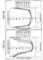
- Figs. 11A, 11B, 12A, 12B, and 13 each depict optical characteristics of the optical scanner.
- FIG. 11A and 11B depicts an optical characteristic curve for the image height Y ranging from +150 to -150.
- the horizontal axis represents a defocus (in the optical axis direction) and the vertical axis represents a beam diameter.
- Fig. 11A depicts plots taken in the main scanning direction with a focal depth of 3.2 millimeters.
- Fig. 11B depicts plots taken in the sub-scanning direction with a focal depth of 5.2 millimeters.
- Fig. 12A depicts field curvatures, with a dashed line corresponding to the main scanning direction and a solid line corresponding to the sub-scanning direction.
- a solid line indicates a constant-velocity characteristic (linearity), and a dashed line indicates an F0 characteristic. The linearity is approximately 0.3%.
- Fig. 13 a graph of deviations in lateral magnification in the sub-scanning direction with respect to the image height.
- the vertical axis represents the image height
- the horizontal axis represents a magnification deviation (%) with reference to a magnification at the image height of 0 millimeter. The deviation is reduced to equal to or lower than 0.2%.
- Fig. 14 is an external perspective view of an example of a scanning-lens deforming unit.
- the scanning-lens deforming unit has a synchronization detecting function of detecting scanning beams at a start point and at an end point of a scanned region, except for a scanning surface 1018 (see (a) and (b) of Fig. 10), to determine a timing at which scanning is to be performed.
- the scanning-lens deforming unit formed integrally with a holder is provided on the second scanning lens 1017 (see (a) and (b) of Fig. 10).
- An upper plate metal 1401 and a lower plate metal 1406 support the scanning lens.
- a taper pin 1402 is moved relative to a bracket 1403, hence a roller 1405 exerts a pressure on the scanning lens parallel to the sub-scanning direction, which deforms the second scanning lens 1017 elongated in the main scanning direction (see (a) and (b) of Fig. 10).
- the second scanning lens 1017 has a large influence on curvature of a scanning line in the sub-scanning direction because the second scanning lens 1017 has a relatively high focal power in the sub-scanning direction.
- the curvature of the scanning line can be corrected.
- the scanning-lens deforming unit shown in Fig. 14 also has a function of tilting the second scanning lens 1017 (see (a) and (b) of Fig. 10) with a leaf spring 1404 and a differential screw mechanism 1407 to correct a tilt of the scanning line, which allows optical scanning with higher quality.
- an LD, an LD array, or a VCSEL having a center wavelength near 655 nanometers or 405 nanometers can be employed.
- the optical paths of a plurality of LDs can be combined using a waveguide such as a prism, a mirror, and an optical fiber.
- a glass aspherical surface, a glass spherical surface, a hybrid lens, a liquid-crystal diffracting element, or a hologram lens can be employed.
- the hole (opening) of the splitter can have a circular, an elliptic, or another shape.
- the size of the hole is desirably larger than that of the opening in the aperture member 1010 to reduce an influence on optical scanning exerted on by a manufacturing error.
- the optical detecting unit can be a glass lens, a mirror having a curvature, or a unit formed with two or more of the lens or the mirror.
- a glass lens having a cylindrical surface a hybrid lens, a liquid-crystal diffracting element, or a hologram lens can be employed.
- the incident mirror is arranged to have an optical path equivalent to that shown in (a) of Fig. 10; that is, allow light to be directly guided from the linear-image forming device 1011 to the polygon mirror without the incident mirror, the mirror is removable. Hence, an influence by a manufacturing error can be reduced.
- Conceivable polygon mirrors vary widely in size and the number of surfaces, any one of such polygon mirrors can achieve the effects of the present invention.
- the optical scanner is explained as a so-called underfilled optical system in which a width of incident light beams in the main scanning direction is smaller than a width of a reflecting facet of a polygon mirror
- a so-called overfilled optical system can be employed.
- a width of incident light beams in the main scanning direction is greater than a width of a reflecting facet of a polygon mirror.
- an amount of light reaching a scanning surface is likely to vary according to an image height, and many of light beams are subjected to vignetting by the polygon mirror. Accordingly, employment of the light source system of the present invention is particularly effective for the overfilled optical system.
- the number of the scanning lens can be two, one for cost reduction, or three or more for quality enhancement.
- the surface shape is obtained by continuously changing a radius of a circle parallel to the Z-X plane about points on non-circular curves in the X-Y plane while satisfying a functional relationship with a position in the main scanning direction.
- the surface can be spherical, cylindrical, or asymmetrical with respect to the main scanning direction.
- the optical scanning unit can be formed with a curved mirror.
- Fig. 15 is a schematic of another example of an optical scanner; (a) is a plan view of the optical scanner, and (b) is a side view thereof.
- the optical scanner is basically similar to that of previous example, and devices downstream the incident mirror are identical to those previously described.
- the optical scanner differs from the previous example in the following points.
- a splitter 1504 is formed integrally with a member corresponding to the aperture member of the optical scanner, which reduces the number of components.
- the size of the opening in the splitter 1504 is 5.2 millimeters in the main scanning direction and 2.1 millimeters in the sub-scanning direction, which are identical to that of the previous example. However, this is a projected size of the opening on the Y-Z plane.
- Using the splitter of a shape as shown in Fig. 16 allows to clip, from light beams F0 (1502), a portion that passes through the opening in the splitter 1504 as light beams FS (1505) and a portion that surrounds the light beams FS (1505) as light beams FM (1506).
- an area of light beams at which the light intensity is 1/e 2 of the peak intensity is defined as an effective beam spot.
- the size of the splitter 1504 in the main scanning and sub-scanning directions is desirably the same as that of the light beam spot.
- the coupling optical element is a circle of which effective area is 7 millimeters in diameter, and collimates light beams into collimated light beams.
- the area of the splitter 1504 on which reflective coating is to be applied is 7.5 mm ⁇ 7.5 mm with consideration given to a manufacturing error.
- the thus-split light beams FS (1505) and the light beams FM (1506) form an angle on a plane parallel to the sub-scanning plane.
- a detector 1508 is disposed on a wall (so-called bottom wall) of an optical housing.
- the light beams FM (1506) and the light beams FS (1505) are split in the main scanning direction, the light beams must be guided to one of walls of the optical housing, the wall being vertical to the main scanning plane (X-Y plane). This lengthens the optical path, and makes the system susceptible to a manufacturing error. Even when a stray light is generated in the light source system, deflecting light beams in the Z direction with respect to the scanning lens and polygon mirror that are elongated in the Y direction prevents the stray light from reaching the scanning surface to form an image.
- a reflecting member 1701 shown in gray, functions as the splitter.
- the reflecting member 1701 is adjacent to the opening only on one side perpendicular to the sub-scanning direction.
- a light-shielding member 1702 functions as the aperture member.
- Fig. 17 is an external perspective view of the modification of the splitter.
- this configuration reduces an area on which the coating is applied by half, and thereby increase a manufacturing efficiency.
- the opening of the splitter of this example is elongated in the Y-direction. Therefore, when light beams are incident on the splitter as circular beams, more light beams are intercepted by the splitter on sides of the opening along the sub-scanning direction than the other sides.
- the optical path can be deflected with a transparent member, such as a diffracting optical element, in place of the reflecting member 1701 shown in Fig. 17.
- a beam shaper 1512 has a coupling optical element 1503 between a light source 1501 and the splitter 1504.
- the splitter 1504 is disposed at a position apart from the coupling optical element 1503 by a substantially rear focal length in the optical axis in the optical axis direction.
- Figs. 18 and 19 are conceptual schematic for explaining effects achieved by using a plurality of light sources.
- control of light amount of the light beams is also attained uniformly.
- the optical scanner can be used to form an image forming apparatus.
- Fig. 20 is an example of an image forming apparatus.
- a plurality of scanning surfaces are scanned for exposure and form a visible image of each multi color.
- the images are superimposed one color image on another to thereby form a color image.
- photosensitive members 2002a to 2002d rotate clockwise at a constant velocity.
- Surfaces of the photosensitive members 2002a to 2002d are uniformly charged by a charger 2005, and scanned for exposure by an optical scanner 2001 in a similar manner as that in above-described image forming apparatus.
- electrostatic latent images are formed on the photosensitive members 2002, and visualized as toner images by a developing unit 2003.
- the toner images formed on the plurality of photosensitive members 2002a to 2002d by a transfer unit 2006 are sequentially transferred to an intermediate transfer belt 2008 to form a single image, thereby forming a superimposed full-color image.
- the full-color image is transferred onto a sheet recording medium S by another transfer unit 2009, and fixed by a fixing unit 2007. Hence, the image forming process is completed, and the medium S is discharged out of the apparatus.
- Residual toner and paper lint on the photosensitive members 2002 are removed by a cleaning unit 2004. Thereafter, the photosensitive members 2002 are charged by the charger 2005 again.
- Cyan C, magenta M, yellow Y, and black Bk can be used as colors for the photosensitive members 2002.
- the colors are desirably determined in accordance with a brightness and saturation.
- Y which is low in saturation or high in brightness is desirably used.
- the photosensitive members have the same size.
- stability of the entire apparatus can be increased.
- the light beams have a substantially circular or elliptic cross section with its intensity peak near the center. Light of the peak portion is supplied to the outside, and light of the remaining portion is detected for control of a light amount. This allows control of the light amount and efficient supply of light to the outside. Efficiency for light utilization is thus improved, which leads to energy saving and reduction of environmental load.
- the light receiving element or the like, which functions as the detector, and the light source are supported on a single substrate or a single base member. Therefore, a necessary footprint can be reduced as compared with a configuration in which the detector and the light source are independently formed, and hence miniaturization of the system and an apparatus using the system are attained.
- a wiring board, a support member, and the like can be used partially in a shared manner. This reduces the number of components and thereby reduces cost and environmental load.
- a light reflecting member such as a mirror as the splitter allows light to be supplied to the detector and/or to the outside highly efficiently with low loss.
- the system can be miniaturized because the optical path can be bent using a mirror.
- a configuration in which the splitter converges light on the detector to thereby function also as the optical detecting unit can be taken.
- the need of forming the optical detecting unit with another component is eliminated, and the number of components is reduced.
- the reduction in the number of components also reduces the footprint for devices, and hence miniaturizes the apparatus.
- a positional deviation of a beam spot can be reduced because light beams are insusceptible to a surface shape of the element in contrast to a surface shape of a reflecting optical element such as a mirror.
- miniaturization of the light receiving element is attained.
- having a sufficient allowance in accuracy of the surface shape improves a yield rate and reduces the cost of the system.
- cross sections of out-of-optical-axis light beams that do not intersect an optical axis of an optical system such as a lens and therefore are at different distances from the optical axis generally do not spatially coincide with one another.
- portions corresponding to different areas in light intensity distribution are subjected to detection. Consequently, the light beams undesirably differ from one another in light amount.
- even chief rays of light beams out of the optical axis intersect with the optical axis, which enables intensity centers of the light beams to align.
- a ratio of a split light amount to a total light amount for each light beam becomes uniform through the light beams.
- a light amount control can be performed uniformly on the plurality of light beams.
- Employment of the light source system enables adjustment of a light amount to a desired value during optical scanning.
- the efficiency in light utilization is also enhanced, which leads to energy saving and reduction of environmental load.
- vignetting of a miniscule number of light beams undesirably occurs at edges of the opening; that is, at a boundary between a light-beam passing portion and a light-beam intercepting portion, due to a limit in machining accuracy.
- the influence of this vignetting is considerably small because a typical aperture member is arranged perpendicular to a traveling direction of the light beams.
- a member, such as the splitter and the aperture member is arranged obliquely to the traveling direction of the light beams rather than perpendicularly, vignetting of light beams occurs depending on the thickness of the member.
- At least one of the splitter and the aperture member is desirably arranged to be rotated about its rotary axis perpendicular to a direction along which longer sides of the opening extend.
- an image-forming optical system that includes the optical scanning unit and the light source system are housed in an optical housing to form the optical scanner.
- a lid of the optical housing is substantially parallel with a main scanning plane. Accordingly, an optical element disposed in the optical housing such that the light beams FS and FM in the light source system are substantially collimated with the main scanning plane is facilitated to receive arrangement and adjustment works in a state with the lid of the optical housing removed.
- each component that forms the light source system in the main scanning plane is considerably restricted (by, e.g., interference between the component and the optical scanning unit or the optical housing), the interference can be avoided by distributing light beams in the sub-scanning direction.
- light reflected from a surface of a lens that converges light to the light receiving element has an angle in the sub-scanning direction. Therefore, the reflected light does not reach a light deflector (e.g., polygon mirror).
- a light deflector e.g., polygon mirror
- the member functioning as the aperture member is processed to have the function as the splitter, thereby integrating the two functions into the single member to reduce cost. This reduces the footprint and hence miniaturizes the apparatus.
- the aperture member and the splitter are configured as separate members, which facilitates manufacturing of them, and hence increases a manufacturing yield rate.
- disposing the splitter upstream from the aperture member to be closer to the light source shortens the optical path from the light source to the detector. This leads to miniaturization of the apparatus, and, even when the apparatus has a manufacturing error, deviation of the beam spot on the detector can be reduced.
- the efficiency for light utilization is increased, which increases an S/N ratio at detection. Accordingly, the light amount can be controlled at high accuracy, which enables excellent optical scanning.
- the splitter can have an easily-manufacturable shape.
- the number of the splitters can be reduced, which allows cost reduction.
- the VCSEL When the VCSEL is used, in contrast to an LD array that uses a plurality of edge-emitting semiconductor laser diodes, as the number of light beams to be emitted increases, the cost is reduced by a greater amount. Meanwhile, the VCSEL has a considerably short cavity length and therefore has a smaller mode hopping than that of the LD array. This allows reduction of degradation in optical scanning quality due to variations in wavelength.
- cross sections of out-of-optical-axis light beams that do not intersect an optical axis of an optical system such as a lens and therefore are at different distances from the optical axis generally do not spatially coincide with one another.
- portions corresponding to different areas in light intensity distribution are subjected to detection/light-amount control/scanning. Consequently, the light beams differ from one another in light amount.
- even chief rays of light beams out of the optical axis intersect with the optical axis, which allows intensity centers of the light beams to align.
- a ratio of a split light amount to a total light amount for each light beam becomes uniform through the light beams.
- a light amount control can be performed uniformly on the plurality of light beams.
- the light amount on the scanning surface can be corrected to coincide with one another highly accurately. This enables excellent optical scanning to be performed with less-uneven exposure.
- the light source system that is increased in utilization efficiency of light emitted from a light source, and the optical scanner capable of performing excellent control of the light amount using the system allow to reduce degradation of image quality and perform highly reliable image forming at low cost while saving energy.
- the optical scanner using the plurality of light beams enables a high-quality image to be formed at high speed.
- the light beams have a substantially circular or elliptic cross section with its intensity peak near the center.
- Light of the peak portion is supplied to the outside, and light of the remaining portion is detected for control of a light amount. This enables control of the light amount and efficient supply of light to the outside. The efficiency for light utilization is thus increased, and energy saving and reduction of environmental load are attained.
Applications Claiming Priority (1)
| Application Number | Priority Date | Filing Date | Title |
|---|---|---|---|
| JP2006124127A JP4847201B2 (ja) | 2006-04-27 | 2006-04-27 | 光源システム、光走査装置、画像形成装置、光量制御方法、光走査方法、及び画像形成方法 |
Publications (2)
| Publication Number | Publication Date |
|---|---|
| EP1850165A1 true EP1850165A1 (fr) | 2007-10-31 |
| EP1850165B1 EP1850165B1 (fr) | 2018-08-01 |
Family
ID=38220045
Family Applications (1)
| Application Number | Title | Priority Date | Filing Date |
|---|---|---|---|
| EP07106285.5A Expired - Fee Related EP1850165B1 (fr) | 2006-04-27 | 2007-04-17 | Système de source lumineuse, lecteur optique, appareil de formation d'images, procédé de contrôle de la quantité de lumière, procédé de lecture optique et procédé de formation d'images |
Country Status (3)
| Country | Link |
|---|---|
| US (1) | US8085457B2 (fr) |
| EP (1) | EP1850165B1 (fr) |
| JP (1) | JP4847201B2 (fr) |
Cited By (1)
| Publication number | Priority date | Publication date | Assignee | Title |
|---|---|---|---|---|
| EP2921877A3 (fr) * | 2014-03-19 | 2015-10-07 | Ricoh Company, Ltd. | Dispositif de détection d'objet et appareil de détection à distance |
Families Citing this family (43)
| Publication number | Priority date | Publication date | Assignee | Title |
|---|---|---|---|---|
| US7924487B2 (en) * | 2007-02-09 | 2011-04-12 | Ricoh Company, Ltd. | Optical scanning device and image forming apparatus |
| US7626744B2 (en) * | 2007-02-27 | 2009-12-01 | Ricoh Company, Limited | Optical scanning device and image forming apparatus |
| US8081203B2 (en) | 2007-03-02 | 2011-12-20 | Ricoh Company, Ltd. | Light-amount detecting device, light source device, optical scanning unit and image forming apparatus |
| JP5224161B2 (ja) * | 2007-04-24 | 2013-07-03 | 株式会社リコー | 光走査装置及び画像形成装置 |
| US7903135B2 (en) * | 2007-04-26 | 2011-03-08 | Ricoh Company, Ltd. | Optical scanning device and image forming apparatus for optimizing arrangement intervals in a main-scanning direction and a sub-scanning direction |
| US8094178B2 (en) | 2007-05-24 | 2012-01-10 | Ricoh Company, Ltd. | Method and apparatus for forming image |
| JP5177399B2 (ja) * | 2007-07-13 | 2013-04-03 | 株式会社リコー | 面発光レーザアレイ、光走査装置及び画像形成装置 |
| US7738007B2 (en) * | 2007-09-04 | 2010-06-15 | Ricoh Company, Ltd. | Optical scanning device and method for adjusting errors |
| JP5163021B2 (ja) | 2007-09-10 | 2013-03-13 | 株式会社リコー | モニタ装置、光源装置、光走査装置及び画像形成装置 |
| JP2009157014A (ja) | 2007-12-26 | 2009-07-16 | Ricoh Co Ltd | 光走査装置及び画像形成装置 |
| JP2009163137A (ja) * | 2008-01-09 | 2009-07-23 | Ricoh Co Ltd | 光走査装置・画像形成装置 |
| JP5439825B2 (ja) | 2008-01-25 | 2014-03-12 | 株式会社リコー | 画像形成装置および画像形成方法 |
| JP5112098B2 (ja) * | 2008-02-05 | 2013-01-09 | 株式会社リコー | 光走査装置及び画像形成装置 |
| JP5316745B2 (ja) * | 2008-03-12 | 2013-10-16 | 株式会社リコー | 光走査装置及び画像形成装置 |
| JP2009244843A (ja) | 2008-03-14 | 2009-10-22 | Ricoh Co Ltd | 光走査装置およびカラー画像形成装置 |
| JP5333982B2 (ja) * | 2008-03-17 | 2013-11-06 | 株式会社リコー | 光源装置、光走査装置及び画像形成装置 |
| JP5439874B2 (ja) * | 2008-03-18 | 2014-03-12 | 株式会社リコー | 画像形成装置および画像形成方法 |
| JP2009265614A (ja) * | 2008-04-03 | 2009-11-12 | Ricoh Co Ltd | 光走査装置及び画像形成装置 |
| JP5034053B2 (ja) | 2008-06-03 | 2012-09-26 | 株式会社リコー | 光走査装置および画像形成装置 |
| JP5103673B2 (ja) | 2008-06-23 | 2012-12-19 | 株式会社リコー | 光走査装置、および画像形成装置 |
| JP5316759B2 (ja) * | 2008-10-16 | 2013-10-16 | 株式会社リコー | 光走査装置、調整方法及び画像形成装置 |
| JP2010122473A (ja) * | 2008-11-20 | 2010-06-03 | Ricoh Co Ltd | 光源装置、光走査装置及び画像形成装置 |
| JP5505618B2 (ja) | 2008-12-25 | 2014-05-28 | 株式会社リコー | 光源装置、光走査装置及び画像形成装置 |
| JP5515723B2 (ja) | 2009-02-02 | 2014-06-11 | 株式会社リコー | 光走査装置、画像形成装置および光通信システム |
| JP5375225B2 (ja) * | 2009-03-16 | 2013-12-25 | 株式会社リコー | 光源装置、光走査装置及び画像形成装置 |
| JP2011022196A (ja) * | 2009-07-13 | 2011-02-03 | Ricoh Co Ltd | 光走査装置および画像形成装置 |
| JP5321903B2 (ja) * | 2009-08-18 | 2013-10-23 | 株式会社リコー | 光源装置、光走査装置及び画像形成装置 |
| JP5333047B2 (ja) | 2009-08-24 | 2013-11-06 | 株式会社リコー | 光書込装置および光書込方法 |
| JP5505617B2 (ja) | 2009-12-10 | 2014-05-28 | 株式会社リコー | 光走査装置及び画像形成装置 |
| JP5321915B2 (ja) * | 2010-02-18 | 2013-10-23 | 株式会社リコー | 光源装置、光走査装置及び画像形成装置 |
| JP5333283B2 (ja) * | 2010-02-19 | 2013-11-06 | 株式会社リコー | 光源装置、光走査装置及び画像形成装置 |
| JP5610127B2 (ja) * | 2010-03-11 | 2014-10-22 | 株式会社リコー | 光走査装置及び画像形成装置 |
| JP2011191370A (ja) | 2010-03-12 | 2011-09-29 | Ricoh Co Ltd | 光走査装置及び画像形成装置 |
| JP2011249763A (ja) * | 2010-04-28 | 2011-12-08 | Ricoh Co Ltd | 光源ユニット、光走査装置及び画像形成装置 |
| JP5531784B2 (ja) | 2010-05-27 | 2014-06-25 | 株式会社リコー | 光走査装置及び画像形成装置 |
| JP5664013B2 (ja) | 2010-08-19 | 2015-02-04 | 株式会社リコー | 光走査装置及び画像形成装置 |
| JP5573493B2 (ja) | 2010-08-25 | 2014-08-20 | 株式会社リコー | 光走査装置及び画像形成装置 |
| DE102011012886B3 (de) * | 2011-03-01 | 2012-05-16 | Jenoptik Optical Systems Gmbh | Justierbare Linsenfassung für eine Streifenlinse |
| JP5853473B2 (ja) * | 2011-08-03 | 2016-02-09 | 株式会社リコー | 光走査装置及び画像形成装置 |
| US8654168B2 (en) * | 2011-08-03 | 2014-02-18 | Ricoh Company, Ltd. | Optical scanning device, image forming apparatus, and optical scanning device designing method |
| JP5900733B2 (ja) | 2011-11-21 | 2016-04-06 | 株式会社リコー | 光走査装置及び画像形成装置 |
| JP6147042B2 (ja) * | 2012-04-25 | 2017-06-14 | キヤノン株式会社 | 画像形成装置 |
| CN114740630B (zh) * | 2022-06-15 | 2022-09-16 | 西安炬光科技股份有限公司 | 一种扫描光学系统及激光应用终端 |
Citations (12)
| Publication number | Priority date | Publication date | Assignee | Title |
|---|---|---|---|---|
| US4192573A (en) * | 1977-02-14 | 1980-03-11 | The United States Of America As Represented By The Secretary Of The Navy | Variable power attenuator for light beams |
| JPS59223187A (ja) * | 1983-06-03 | 1984-12-14 | Mitsubishi Electric Corp | レ−ザ配光制御システム |
| EP0143743A1 (fr) * | 1983-10-28 | 1985-06-05 | Ciba-Geigy Ag | Dispositif laser pour le traitement des matériaux |
| US4638456A (en) * | 1984-01-27 | 1987-01-20 | E. I. Du Pont De Nemours And Company | Spot quantitation |
| EP0269122A2 (fr) * | 1986-11-28 | 1988-06-01 | Fuji Photo Film Co., Ltd. | Système optique pour laser |
| US5161238A (en) * | 1988-05-27 | 1992-11-03 | Lambda Physik Forschungs-Und Entwicklungs-Gesellschaft Gmbh | Apparatus for confining laser beams |
| EP0713112A1 (fr) * | 1994-11-17 | 1996-05-22 | ANT Nachrichtentechnik GmbH | Dispositif optique récepteur émetteur avec un laser émettant au niveau de la surface |
| JP2002280655A (ja) * | 2001-01-10 | 2002-09-27 | Ricoh Opt Ind Co Ltd | 光出力装置および光出力装置用レンズ素子 |
| JP2003060299A (ja) * | 2001-06-07 | 2003-02-28 | Ricoh Opt Ind Co Ltd | 光出力素子・光出力素子アレイおよびレンズ素子・レンズ素子アレイ |
| EP1434161A1 (fr) * | 2001-08-31 | 2004-06-30 | Optoelectronics Co., Ltd. | Module pour lecteur d'informations optique |
| US20040264881A1 (en) * | 2003-06-26 | 2004-12-30 | Posamentier Joshua D. | Laser power monitoring tap |
| JP2005156933A (ja) * | 2003-11-26 | 2005-06-16 | Fuji Xerox Co Ltd | 光走査装置 |
Family Cites Families (15)
| Publication number | Priority date | Publication date | Assignee | Title |
|---|---|---|---|---|
| CA2065368A1 (fr) * | 1989-08-21 | 1991-02-22 | Carl R. Amos | Methode et dispositif convenant a la manipulation de phenomenes electromagnetiques |
| JPH03227226A (ja) | 1990-02-01 | 1991-10-08 | Japan Steel Works Ltd:The | 中空袋の製造方法及び装置 |
| JP3409772B2 (ja) * | 1991-05-14 | 2003-05-26 | セイコーエプソン株式会社 | 画像形成装置 |
| JPH06106775A (ja) * | 1992-09-29 | 1994-04-19 | Ricoh Co Ltd | レーザ記録装置 |
| JPH06164070A (ja) * | 1992-11-27 | 1994-06-10 | Ricoh Co Ltd | 光走査用光源装置 |
| JPH07281114A (ja) * | 1993-08-23 | 1995-10-27 | Ricoh Co Ltd | 光走査装置 |
| US5844707A (en) * | 1996-01-31 | 1998-12-01 | Asahi Kogaku Kogyo Kabushiki Kaisha | Scanning optical device |
| JPH10100476A (ja) | 1996-09-16 | 1998-04-21 | Xerox Corp | 垂直キャビティレーザダイオード用積分式フィードバックアセンブリ |
| JP2002026445A (ja) | 2000-07-11 | 2002-01-25 | Ricoh Co Ltd | 光源装置 |
| JP2004087816A (ja) * | 2002-08-27 | 2004-03-18 | Dainippon Screen Mfg Co Ltd | 光源装置および画像記録装置 |
| JP2005274678A (ja) * | 2004-03-23 | 2005-10-06 | Fuji Xerox Co Ltd | 光学走査装置 |
| JP2006091157A (ja) * | 2004-09-21 | 2006-04-06 | Fuji Xerox Co Ltd | 光走査装置 |
| US7652244B2 (en) * | 2004-10-05 | 2010-01-26 | Finisar Corporation | Combined laser transmitter and photodetector receiver package |
| JP2006259098A (ja) * | 2005-03-16 | 2006-09-28 | Fuji Xerox Co Ltd | 光走査装置 |
| JP4530922B2 (ja) | 2005-06-20 | 2010-08-25 | 株式会社リコー | 光走査装置および画像形成装置 |
-
2006
- 2006-04-27 JP JP2006124127A patent/JP4847201B2/ja active Active
-
2007
- 2007-04-17 EP EP07106285.5A patent/EP1850165B1/fr not_active Expired - Fee Related
- 2007-04-17 US US11/736,313 patent/US8085457B2/en not_active Expired - Fee Related
Patent Citations (12)
| Publication number | Priority date | Publication date | Assignee | Title |
|---|---|---|---|---|
| US4192573A (en) * | 1977-02-14 | 1980-03-11 | The United States Of America As Represented By The Secretary Of The Navy | Variable power attenuator for light beams |
| JPS59223187A (ja) * | 1983-06-03 | 1984-12-14 | Mitsubishi Electric Corp | レ−ザ配光制御システム |
| EP0143743A1 (fr) * | 1983-10-28 | 1985-06-05 | Ciba-Geigy Ag | Dispositif laser pour le traitement des matériaux |
| US4638456A (en) * | 1984-01-27 | 1987-01-20 | E. I. Du Pont De Nemours And Company | Spot quantitation |
| EP0269122A2 (fr) * | 1986-11-28 | 1988-06-01 | Fuji Photo Film Co., Ltd. | Système optique pour laser |
| US5161238A (en) * | 1988-05-27 | 1992-11-03 | Lambda Physik Forschungs-Und Entwicklungs-Gesellschaft Gmbh | Apparatus for confining laser beams |
| EP0713112A1 (fr) * | 1994-11-17 | 1996-05-22 | ANT Nachrichtentechnik GmbH | Dispositif optique récepteur émetteur avec un laser émettant au niveau de la surface |
| JP2002280655A (ja) * | 2001-01-10 | 2002-09-27 | Ricoh Opt Ind Co Ltd | 光出力装置および光出力装置用レンズ素子 |
| JP2003060299A (ja) * | 2001-06-07 | 2003-02-28 | Ricoh Opt Ind Co Ltd | 光出力素子・光出力素子アレイおよびレンズ素子・レンズ素子アレイ |
| EP1434161A1 (fr) * | 2001-08-31 | 2004-06-30 | Optoelectronics Co., Ltd. | Module pour lecteur d'informations optique |
| US20040264881A1 (en) * | 2003-06-26 | 2004-12-30 | Posamentier Joshua D. | Laser power monitoring tap |
| JP2005156933A (ja) * | 2003-11-26 | 2005-06-16 | Fuji Xerox Co Ltd | 光走査装置 |
Cited By (2)
| Publication number | Priority date | Publication date | Assignee | Title |
|---|---|---|---|---|
| EP2921877A3 (fr) * | 2014-03-19 | 2015-10-07 | Ricoh Company, Ltd. | Dispositif de détection d'objet et appareil de détection à distance |
| US10031212B2 (en) | 2014-03-19 | 2018-07-24 | Ricoh Company, Ltd. | Object detection device and remote sensing apparatus |
Also Published As
| Publication number | Publication date |
|---|---|
| EP1850165B1 (fr) | 2018-08-01 |
| JP2007298563A (ja) | 2007-11-15 |
| JP4847201B2 (ja) | 2011-12-28 |
| US8085457B2 (en) | 2011-12-27 |
| US20070253047A1 (en) | 2007-11-01 |
Similar Documents
| Publication | Publication Date | Title |
|---|---|---|
| EP1850165B1 (fr) | Système de source lumineuse, lecteur optique, appareil de formation d'images, procédé de contrôle de la quantité de lumière, procédé de lecture optique et procédé de formation d'images | |
| US8102411B2 (en) | Optical scanner and image forming apparatus | |
| US7215453B2 (en) | Optical system having extended angular scan range | |
| EP0804015B1 (fr) | Dispositif de balayage optique | |
| US8624951B2 (en) | Optical scanning device and image forming apparatus | |
| US6489982B2 (en) | Error reduction in a multi-beam scanning optical system, and image-forming apparatus using the same | |
| US8094179B2 (en) | Light source device, optical scanning device, and image forming apparatus | |
| KR100856154B1 (ko) | 주사광학장치 및 그것을 이용한 화상형성장치 | |
| US20040125192A1 (en) | Light source and light beam scanning unit | |
| US7253936B2 (en) | Laser scanning unit | |
| US20010052927A1 (en) | Light source unit for optical scanning device | |
| US6950216B2 (en) | Light source apparatus and optical scanner | |
| US6791728B2 (en) | Scanning optical device and image forming apparatus | |
| US7149009B2 (en) | Scanning optical apparatus, image forming apparatus, and adjusting method therefor | |
| EP1248135B1 (fr) | Système optique de balayage à plusieurs faisceaux et appareil de formation d'images l'utilisant | |
| US6927883B1 (en) | Light-scanning optical apparatus and image forming apparatus | |
| US6922296B2 (en) | Optical path adjusting device | |
| JP2002228962A (ja) | 光学素子及びそれを用いた光走査装置 | |
| JPH08304728A (ja) | 光走査装置のスリット板装着構造 | |
| JP7373365B2 (ja) | 光走査装置 | |
| US6549318B2 (en) | Optical scanner assembly | |
| JP2008216514A (ja) | 光走査装置及び画像形成装置 | |
| JP2001042238A (ja) | マルチビーム走査装置 | |
| JP2003075750A (ja) | 走査光学装置及びそれを用いた画像形成装置 | |
| JP2003121772A (ja) | 光走査装置 |
Legal Events
| Date | Code | Title | Description |
|---|---|---|---|
| PUAI | Public reference made under article 153(3) epc to a published international application that has entered the european phase |
Free format text: ORIGINAL CODE: 0009012 |
|
| AK | Designated contracting states |
Kind code of ref document: A1 Designated state(s): AT BE BG CH CY CZ DE DK EE ES FI FR GB GR HU IE IS IT LI LT LU LV MC MT NL PL PT RO SE SI SK TR |
|
| AX | Request for extension of the european patent |
Extension state: AL BA HR MK YU |
|
| 17P | Request for examination filed |
Effective date: 20080304 |
|
| 17Q | First examination report despatched |
Effective date: 20080408 |
|
| AKX | Designation fees paid |
Designated state(s): BE DE FR GB NL |
|
| REG | Reference to a national code |
Ref country code: DE Ref legal event code: R079 Ref document number: 602007055552 Country of ref document: DE Free format text: PREVIOUS MAIN CLASS: G02B0026120000 Ipc: G02B0027090000 |
|
| GRAP | Despatch of communication of intention to grant a patent |
Free format text: ORIGINAL CODE: EPIDOSNIGR1 |
|
| RIC1 | Information provided on ipc code assigned before grant |
Ipc: G02B 27/09 20060101AFI20180129BHEP Ipc: G02B 19/00 20060101ALI20180129BHEP Ipc: G02B 26/12 20060101ALI20180129BHEP |
|
| INTG | Intention to grant announced |
Effective date: 20180219 |
|
| GRAS | Grant fee paid |
Free format text: ORIGINAL CODE: EPIDOSNIGR3 |
|
| GRAA | (expected) grant |
Free format text: ORIGINAL CODE: 0009210 |
|
| AK | Designated contracting states |
Kind code of ref document: B1 Designated state(s): BE DE FR GB NL |
|
| REG | Reference to a national code |
Ref country code: GB Ref legal event code: FG4D |
|
| REG | Reference to a national code |
Ref country code: DE Ref legal event code: R096 Ref document number: 602007055552 Country of ref document: DE |
|
| REG | Reference to a national code |
Ref country code: NL Ref legal event code: MP Effective date: 20180801 |
|
| PG25 | Lapsed in a contracting state [announced via postgrant information from national office to epo] |
Ref country code: NL Free format text: LAPSE BECAUSE OF FAILURE TO SUBMIT A TRANSLATION OF THE DESCRIPTION OR TO PAY THE FEE WITHIN THE PRESCRIBED TIME-LIMIT Effective date: 20180801 |
|
| REG | Reference to a national code |
Ref country code: DE Ref legal event code: R097 Ref document number: 602007055552 Country of ref document: DE |
|
| PLBE | No opposition filed within time limit |
Free format text: ORIGINAL CODE: 0009261 |
|
| STAA | Information on the status of an ep patent application or granted ep patent |
Free format text: STATUS: NO OPPOSITION FILED WITHIN TIME LIMIT |
|
| 26N | No opposition filed |
Effective date: 20190503 |
|
| REG | Reference to a national code |
Ref country code: BE Ref legal event code: MM Effective date: 20190430 |
|
| PG25 | Lapsed in a contracting state [announced via postgrant information from national office to epo] |
Ref country code: BE Free format text: LAPSE BECAUSE OF NON-PAYMENT OF DUE FEES Effective date: 20190430 |
|
| PGFP | Annual fee paid to national office [announced via postgrant information from national office to epo] |
Ref country code: GB Payment date: 20220420 Year of fee payment: 16 Ref country code: FR Payment date: 20220421 Year of fee payment: 16 Ref country code: DE Payment date: 20220420 Year of fee payment: 16 |
|
| P01 | Opt-out of the competence of the unified patent court (upc) registered |
Effective date: 20230522 |
|
| REG | Reference to a national code |
Ref country code: DE Ref legal event code: R119 Ref document number: 602007055552 Country of ref document: DE |
|
| GBPC | Gb: european patent ceased through non-payment of renewal fee |
Effective date: 20230417 |
|
| PG25 | Lapsed in a contracting state [announced via postgrant information from national office to epo] |
Ref country code: GB Free format text: LAPSE BECAUSE OF NON-PAYMENT OF DUE FEES Effective date: 20230417 |
|
| PG25 | Lapsed in a contracting state [announced via postgrant information from national office to epo] |
Ref country code: GB Free format text: LAPSE BECAUSE OF NON-PAYMENT OF DUE FEES Effective date: 20230417 Ref country code: FR Free format text: LAPSE BECAUSE OF NON-PAYMENT OF DUE FEES Effective date: 20230430 Ref country code: DE Free format text: LAPSE BECAUSE OF NON-PAYMENT OF DUE FEES Effective date: 20231103 |