EP0804015B1 - Dispositif de balayage optique - Google Patents
Dispositif de balayage optique Download PDFInfo
- Publication number
- EP0804015B1 EP0804015B1 EP97106632A EP97106632A EP0804015B1 EP 0804015 B1 EP0804015 B1 EP 0804015B1 EP 97106632 A EP97106632 A EP 97106632A EP 97106632 A EP97106632 A EP 97106632A EP 0804015 B1 EP0804015 B1 EP 0804015B1
- Authority
- EP
- European Patent Office
- Prior art keywords
- light
- optical
- light source
- light beams
- polarization
- Prior art date
- Legal status (The legal status is an assumption and is not a legal conclusion. Google has not performed a legal analysis and makes no representation as to the accuracy of the status listed.)
- Expired - Lifetime
Links
Images

Classifications
-
- H—ELECTRICITY
- H04—ELECTRIC COMMUNICATION TECHNIQUE
- H04N—PICTORIAL COMMUNICATION, e.g. TELEVISION
- H04N1/00—Scanning, transmission or reproduction of documents or the like, e.g. facsimile transmission; Details thereof
- H04N1/04—Scanning arrangements, i.e. arrangements for the displacement of active reading or reproducing elements relative to the original or reproducing medium, or vice versa
- H04N1/19—Scanning arrangements, i.e. arrangements for the displacement of active reading or reproducing elements relative to the original or reproducing medium, or vice versa using multi-element arrays
- H04N1/191—Scanning arrangements, i.e. arrangements for the displacement of active reading or reproducing elements relative to the original or reproducing medium, or vice versa using multi-element arrays the array comprising a one-dimensional array, or a combination of one-dimensional arrays, or a substantially one-dimensional array, e.g. an array of staggered elements
- H04N1/1911—Simultaneously or substantially simultaneously scanning picture elements on more than one main scanning line, e.g. scanning in swaths
-
- G—PHYSICS
- G06—COMPUTING OR CALCULATING; COUNTING
- G06K—GRAPHICAL DATA READING; PRESENTATION OF DATA; RECORD CARRIERS; HANDLING RECORD CARRIERS
- G06K15/00—Arrangements for producing a permanent visual presentation of the output data, e.g. computer output printers
- G06K15/02—Arrangements for producing a permanent visual presentation of the output data, e.g. computer output printers using printers
- G06K15/12—Arrangements for producing a permanent visual presentation of the output data, e.g. computer output printers using printers by photographic printing, e.g. by laser printers
-
- B—PERFORMING OPERATIONS; TRANSPORTING
- B41—PRINTING; LINING MACHINES; TYPEWRITERS; STAMPS
- B41J—TYPEWRITERS; SELECTIVE PRINTING MECHANISMS, i.e. MECHANISMS PRINTING OTHERWISE THAN FROM A FORME; CORRECTION OF TYPOGRAPHICAL ERRORS
- B41J2/00—Typewriters or selective printing mechanisms characterised by the printing or marking process for which they are designed
- B41J2/435—Typewriters or selective printing mechanisms characterised by the printing or marking process for which they are designed characterised by selective application of radiation to a printing material or impression-transfer material
- B41J2/47—Typewriters or selective printing mechanisms characterised by the printing or marking process for which they are designed characterised by selective application of radiation to a printing material or impression-transfer material using the combination of scanning and modulation of light
- B41J2/471—Typewriters or selective printing mechanisms characterised by the printing or marking process for which they are designed characterised by selective application of radiation to a printing material or impression-transfer material using the combination of scanning and modulation of light using dot sequential main scanning by means of a light deflector, e.g. a rotating polygonal mirror
-
- G—PHYSICS
- G02—OPTICS
- G02B—OPTICAL ELEMENTS, SYSTEMS OR APPARATUS
- G02B26/00—Optical devices or arrangements for the control of light using movable or deformable optical elements
- G02B26/08—Optical devices or arrangements for the control of light using movable or deformable optical elements for controlling the direction of light
- G02B26/10—Scanning systems
- G02B26/12—Scanning systems using multifaceted mirrors
- G02B26/123—Multibeam scanners, e.g. using multiple light sources or beam splitters
-
- H—ELECTRICITY
- H04—ELECTRIC COMMUNICATION TECHNIQUE
- H04N—PICTORIAL COMMUNICATION, e.g. TELEVISION
- H04N1/00—Scanning, transmission or reproduction of documents or the like, e.g. facsimile transmission; Details thereof
- H04N1/04—Scanning arrangements, i.e. arrangements for the displacement of active reading or reproducing elements relative to the original or reproducing medium, or vice versa
- H04N1/19—Scanning arrangements, i.e. arrangements for the displacement of active reading or reproducing elements relative to the original or reproducing medium, or vice versa using multi-element arrays
- H04N1/191—Scanning arrangements, i.e. arrangements for the displacement of active reading or reproducing elements relative to the original or reproducing medium, or vice versa using multi-element arrays the array comprising a one-dimensional array, or a combination of one-dimensional arrays, or a substantially one-dimensional array, e.g. an array of staggered elements
-
- H—ELECTRICITY
- H04—ELECTRIC COMMUNICATION TECHNIQUE
- H04N—PICTORIAL COMMUNICATION, e.g. TELEVISION
- H04N1/00—Scanning, transmission or reproduction of documents or the like, e.g. facsimile transmission; Details thereof
- H04N1/04—Scanning arrangements, i.e. arrangements for the displacement of active reading or reproducing elements relative to the original or reproducing medium, or vice versa
- H04N1/113—Scanning arrangements, i.e. arrangements for the displacement of active reading or reproducing elements relative to the original or reproducing medium, or vice versa using oscillating or rotating mirrors
- H04N1/1135—Scanning arrangements, i.e. arrangements for the displacement of active reading or reproducing elements relative to the original or reproducing medium, or vice versa using oscillating or rotating mirrors for the main-scan only
Definitions
- the present invention relates to an optical scanning device as well as to a laser beam printer apparatus (LBP) or the like comprising an optical scanning device, which records an image by optically scanning a photosensitive body surface as the surface to be scanned with a plurality of light beams (bundles of rays), which are emitted by a plurality of light-emitting portions of a light source means, and are guided toward the photosensitive body surface via a light deflector such as a rotary polygonal mirror or the like.
- LBP laser beam printer apparatus
- Such multi-beam optical scanning device has a plurality of light-emitting portions (laser tips) as a light source means, and simultaneously optically scans a recording medium surface with a plurality of beam spots which are formed on the recording medium surface by imaging a plurality of light beams emitted by the plurality of light-emitting portions by an imaging lens via a light deflector.
- the number of times of optically scanning the recording medium surface per unit time must be very large, and as a consequence, the rotational speed of the light deflector, image clocks, and the like cannot follow such large number of times of optical scanning. Accordingly, if the number of beam spots that simultaneously scan the recording medium surface is increased, the rotational speed of the light deflector, image clocks, and the like decrease in inverse proportion to the number of beam spots.
- a laser element serving as a light source has a plurality of light-emitting points (light-emitting portions) which can be driven independently.
- Such laser element having a plurality of light-emitting points is generally called a "monolithic multi-beam laser element".
- the monolithic multi-beam laser element When the monolithic multi-beam laser element is used, various optical elements arranged after the light source can be commonly used by the plurality of light beams, thus providing large merits in terms of cost, working, adjustments, and the like.
- the monolithic multi-beam laser elements include, e.g., a so-called surface-emission laser (surface-emission type semiconductor laser).
- the surface-emission laser emits a light beam in a direction parallel to the direction of thickness of a silicon layer
- a conventional semiconductor laser emits a light beam in a direction perpendicular to the direction of thickness of the silicon layer
- the surface-emission laser has the following feature. That is, the conventional semiconductor laser emits divergent light, which has an elliptic section and suffers large variations in divergent angle, while the surface-emission laser can emit a circular beam having a stable divergent angle.
- the surface-emission laser has a problem, i.e., has an unstable direction of polarization of the output light beam.
- the direction of polarization can be controlled to some extent by the manufacturing method, the direction of polarization fluctuates depending on variations in units of light-emitting points, ambient temperature, and outputs.
- the reflectances, transmittances, and angle characteristics of optical elements that build the optical scanning device e.g., a polygonal mirror as a light deflector, a scanning lens (f- ⁇ lens) as an imaging optical system, a return mirror for changing the optical path, and the like change depending on the direction of polarization of the input light beam.
- a monolithic multi-beam laser element comprising a surface-emission laser
- a plurality of beam spots that optically scan the recording medium surface have different intensities in correspondence with the different directions of polarization of the individual light-emitting points, and such differences in intensity appear as pitch nonuniformities on an image, thus considerably deteriorating the image quality.
- EP 0 697 782 A2 discloses an optical scanning device having a light source means comprising a semiconductor laser array with a plurality of light emitting portions. By carefully designing and manufacturing said light source means, the polarization direction of each of the plurality of light beams emitted by said light source means can be aligned to all other such that the composit light beam has a specific predetermined polarization.
- US 5295148A teaches the manufacturing technique of light source means comprising a semiconductor laser array with a plurality of light emitting portions, wherein the polarization direction of each of the plurality of light beams emitted by said light source means is aligned to all other such that the composit light beam has a specific predetermined polarization.
- Such light source means can only be realized at substantially enhanced costs disadvantages.
- the reflectances, transmittances, and the like of optical elements after the polarization direction agreement means hereafter also called polarization limiting means, can have equal characteristics with respect to the plurality of light beams, and light quantity differences in units of beam spots can be eliminated.
- a preferred embodiment relates to an optical scanning device which can obtain both p- and s-polarized light components by polarizing the directions of polarization of light beams emitted by a plurality of light-emitting portions in nearly a 45° direction with respect to the main scanning direction.
- an optical scanning device which comprises a light quantity detection means for detecting the intensities of a plurality of light beams emitted by a plurality of light-emitting portions of a light source means in an optical path between a light limiting means and a deflection means, and a control means for controlling the light source means on the basis of the detected values obtained from the light quantity detection means so that the plurality of light beams that have passed through the polarization limiting means have equal intensities, thereby suppressing variations in light quantity of the plurality of light beams.
- Fig. 1 is a schematic view showing principal part of an optical scanning device used in a laser beam printer apparatus according to the first embodiment of the present invention.
- a monolithic multi-beam laser element 1 serves as a light source means, and comprises a surface-emission laser.
- the surface-emission laser 1 has a plurality of light-emitting portions (laser tips) in the direction of an arrow Z (sub-scanning direction) in Fig. 1, and the light beams emitted by the plurality of light-emitting portions are polarized in a substantially 45° direction with respect to the main scanning direction (the direction of an arrow Y in Fig. 1) perpendicular to the optical axis direction and the sub-scanning direction (Z-direction).
- the plurality of light-emitting portions can be subjected to light modulation independently.
- a collimator lens 2 converts the plurality of light beams (bundles of rays) emitted by the surface-emission laser 1 into collimated light beams or light beams having a predetermined divergence or convergence angle.
- An aperture 3 shapes the outer shapes of the light beams. Note that these elements, i.e., the surface-emission laser 1, the collimator lens 2, and the aperture 3 constitute a light source unit 4.
- the light source unit 4 outputs a plurality of light beams which have similar outer shapes and divergent or convergent angles, but the angles of polarization (directions of polarization) of the individual light beams do not agree with each other.
- a polarizer (polarization plate) 10 serves as a polarization limiting means, and is inserted in the optical path between the light source means 1 and a deflection means 1 (to be described later).
- the polarizer 10 has an optical function of passing only polarized light components in a predetermined direction. More specifically, the polarizer 10 of this embodiment serves to pass only specific polarized light components of the incident light beams, so that the reflectances, transmittances, and the like of the individual optical elements after the polarizer 10 can have equal characteristics with respect to the plurality of light beams, thereby eliminating light quantity differences in units of beam spots.
- An anamorphic lens (cylindrical lens) 5 has a positive refractive power in only the sub-scanning direction. Note that the collimator lens 2 and the cylindrical lens 5 are elements to constitute an optical means 11.
- a light deflector 6 serves as a deflection means, and comprises, e.g., a polygonal mirror.
- the light deflector 6 is rotated by a driving unit (not shown) in the direction of an arrow A in Fig. 1 at a constant rotational speed.
- a scanning lens system 7 serves as an imaging means, and comprises a single anamorphic lens (scanning lens) using a plastic aspherical surface.
- the scanning lens 7 has, in a scanning plane (main scanning direction), so-called f- ⁇ characteristics for imaging light beams which are deflected and incident at equal angular velocities into beam spots that move at equal velocities on scanning lines 8 and 9 (to be described later).
- the scanning lens 7 has, in the sub-scanning direction perpendicular to the scanning plane, a so-called tilt correction function of setting an imaging relationship between the deflection surface (polygonal mirror surface) illuminated with the light beams focused by the above-mentioned cylindrical lens 5 in the sub-scanning direction, and the surface to be scanned.
- the scanning plane indicates a light beam section which is time-serially formed by the light beams deflectively reflected by the deflection surface of the light deflector.
- the scanning lines 8 and 9 correspond to the two light beams emitted by the two light-emitting portions.
- these scanning lines 8 and 9 match a photosensitive body surface (the surface to be scanned) 12 as the recording medium.
- a plurality of light beams emitted by the surface-emission laser 1 having the plurality of light-emitting portions, which can be independently subjected to optical modulation, are converted into nearly collimated beams by the collimator lens 2, and their outer shapes are limited by the aperture 3.
- predetermined polarized light components of the light beams pass through the polarizer 10 and are linearly imaged on a deflection surface 6a of the light deflector (polygonal mirror) 6 via the cylindrical lens 5.
- the plurality of light beams deflectively reflected by the deflection surface 6a are guided onto the surface to be scanned (photosensitive body surface) 12 via the scanning lens 7, thus forming beam spots.
- the surface 12 to be scanned is scanned with multiple beams in the direction of the arrow B, thus performing image recording on the photosensitive drum surface as the recording medium.
- Fig. 2 is an explanatory view showing the directions of polarization of light beams emitted by a plurality of light-emitting points of the surface-emission laser shown in Fig. 1, and the directions of polarization and the amplitudes of the light beams that have passed through the polarizer.
- polarizers 21 and 22 are depicted as parallel stripe patterns with respect to the directions of polarization that can pass.
- the polarizer 21 in Fig. 2 passes only polarized light in the sub-scanning direction, and the polarizer 22 passes only polarized light in the main scanning direction.
- Light-emitting points (light-emitting portions) 2A and 2B are formed on the surface-emission laser 1.
- the directions of polarization of the light beams emitted by the two light-emitting points 2A and 2B are respectively indicated by arrows 1A and 1B, and these two polarized light components have tilts of angles ⁇ a and ⁇ b with respect to the main scanning direction, if the direction parallel to the plane of drawing of Fig. 2 is defined as the main scanning direction.
- the multi-beam laser element is preferably manufactured so that these angles ⁇ a and ⁇ b are about 45° with respect to the main scanning direction. However, these angles vary with errors of about ⁇ 20° due to manufacturing errors and the like.
- the polarizer 21 that passes only polarized light in the sub-scanning direction is used for a plurality of light beams emitted by the light-emitting points 2A and 2B in Fig. 2, these light beams have polarized states, as indicated by arrows 2A' and 2B' shown in Fig. 2. Note that the polarizer itself produces light losses in practice, but such light losses are equally produced in the two light beams and are not expressed here. At this time, the two light beams having the polarized states 2A' and 2B' are polarized in only the sub-scanning direction, and have amplitudes sin ⁇ a and sin ⁇ b, which are different from each other.
- the polarizer 22 that passes only polarized light in the main scanning direction when used for the light beams, these light beams have polarized states, as indicated by arrows 2A" and 2B" shown in Fig. 2.
- the two light beams having the polarized states 2A" and 2B" are polarized in only the main scanning direction, and have amplitudes cos ⁇ a and cos ⁇ b, which are different from each other.
- whether the direction of polarization of a light beam in a single scanning system is to agree with the main scanning direction or sub-scanning direction is determined depending on the surface reflection characteristics of the optical elements that build the scanning system.
- the optical elements since reflection by the light deflector (polygonal mirror) and refraction by the scanning lens mostly occur within the scanning plane, if the direction of polarization agrees with the main scanning direction, the optical elements primarily have reflection characteristics of p-polarized light; if the direction of polarization agrees with the sub-scanning direction, the optical elements primarily have reflection characteristics of s-polarized light.
- the scanning lens surface is not coated with any film, light losses upon reflection by the scanning lens surface decrease as the incident angle becomes larger within the practical range in the case of p-polarized light; but they increase in the case of s-polarized light.
- the light deflector preferably has a constant reflectance independently of the reflection angle, and in order to realize such characteristics, the reflection surface is coated with, e.g., a metal film.
- the characteristics to be imparted differ in correspondence with the p- or s-polarized light components, and the characteristics to be used are determined by, e.g., the manufacturing method of a film.
- Such optical scanning device normally uses a plurality of mirrors to bend the optical path of the scanning system.
- the reflectances and angle characteristics of these mirrors also differ depending on the directions of polarization of incident light beams.
- the light quantity distributions (intensity distributions) at the scanning positions (image heights) of the scanning lines 8 and 9 formed by these beams are expressed by light quantity distribution curves 31 and 32 shown in Fig. 3. These distributions cause changes in density in units of scanning lines, and considerably deteriorate the image quality.
- the above-mentioned polarizer 21 or 22 is inserted in the optical path between the surface-emission laser 1 and the light deflector 6 in consideration of the surface reflection characteristics and the like of the individual optical elements that make up the scanning system, the directions of polarization of the two light beams are limited to one direction, and changes in reflectance depending on the field angles are equalized between the two light beams, thereby eliminating light quantity differences in units of beam spots.
- the two light beams that have passed through the polarizer (21, 22) have the same direction of polarization but have different amplitudes.
- the two scanning lines have different exposures on the photosensitive body surface and form density pitch nonuniformity, thus impairing the image quality.
- the intensities (light quantities) of the plurality of light beams are measured by a measurement means in the optical path between the polarizer 10 and the photosensitive body surface 12, and a control means 13 (laser drive circuit) individually controls (adjusts) the light-emission intensities of the plurality of light-emitting portions so that the measurement means can obtain equal measured values.
- a control means 13 laser drive circuit
- the light-emission intensities of the light-emitting portions may be adjusted during assembly of the optical scanning device or may be adjusted by performing, e.g., feedback control during operation of the optical scanning device.
- the plurality of light beams emitted by the plurality of light-emitting portions have polarized light components in both the main scanning direction and sub-scanning direction perpendicular to the main scanning direction, the subsequent refraction, reflection, and the like can be obtained from both the p- and s-polarized light components depending on the angle of the polarizer 10.
- Fig. 4 is a schematic view showing principal part of the second embodiment of the present invention.
- the same reference numerals in Fig. 4 denote the same parts as in Fig. 1.
- the difference from the first embodiment described above is that the polarization limiting means and the cylindrical lens that makes up the optical means are integrally formed, and the lens surface of the cylindrical lens has a function of a polarizer.
- Other arrangements and optical effects are substantially the same as those in the first embodiment described above, thereby obtaining the same effect.
- a cylindrical lens 40 is formed with a film that has a function of a polarizer on its lens surface 40a on the side of the light source unit 4.
- the polarization limiting means is formed integrally with the cylindrical lens 40, the number of parts can be reduced, thus making the entire device compact.
- the cylindrical lens 40 has the function of the polarizer.
- other optical elements that make up an optical means 11, e.g., the collimator lens 2 may have a function of a polarizer.
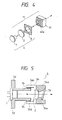
- Fig. 5 is a schematic view showing principal part of the third embodiment of the present invention.
- the same reference numerals in Fig. 5 denote the same parts as in Fig. 1.
- the difference from the first embodiment described above is that the polarizer (polarization plate) is integrated with the light source unit, and is tilted from a direction perpendicular to the optical axis of the collimator lens.
- Other arrangements and optical effects are substantially the same as those in the first embodiment described above, thereby obtaining the same effect.
- a polarizer (polarization plate) 56 is held by a collimator lens holder 54 as a holding means (to be described later), and is tilted not in a direction perpendicular to the optical axis of the collimator lens 2 but in a predetermined direction.
- a light source holder 52 holds the surface-emission laser 1 as the light source.
- the collimator lens holder 54 is formed by plastic two-color molding, and a hatched portion 54a in Fig. 5 is made up of a light-shielding material. The opening of the hatched portion 54a serves as an aperture. The remaining white portion is a transparent portion 54b.
- An ultraviolet-curing adhesive 55 is applied between the transparent portion 54b and the light source holder 52, and ultraviolet rays are irradiated via the transparent portion 54b, thus joining the collimator lens holder 54 to the light source holder 52.
- the polarizer 56 is integrated with the light source unit 4 and is tilted from the direction perpendicular to the optical axis of the collimator lens 2, the entire device can be rendered compact. Also, even when light beams emerging from the collimator lens 2 are reflected by the polarizer 56, the reflected light beams can be prevented from returning to the surface-emission laser 1 via the collimator lens 2 again, thus stabilizing the operation of the surface-emission laser 1.
- the polarizer 56 is integrated with the light source unit 4, and is tilted with respect to the optical axis of the collimator lens 2.
- the present invention is not limited to such specific arrangement.
- the polarizer 56 may be arranged independently of the light source unit 4, and may be tilted from the direction perpendicular to the optical axis.
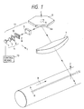
- Fig. 6 is a schematic view showing principal part of the fourth embodiment of the present invention.
- the same reference numerals in Fig. 6 denote the same parts as in Fig. 1.
- the direction of the polarizer need only be basically selected to obtain nearly constant exposures on the photosensitive body surface in consideration of the characteristics of optical members present in the optical path between the light deflector and the photosensitive body surface (the surface to be scanned).
- a polarizer 61 serving as a polarization limiting means is pivotal about the optical axis of the collimator lens 2 to effectively select the direction of the polarizer 61.
- the polarizer 61 is shaped to have a cylindrical shape, and is held by a holding member 62 with a V-shaped groove.
- a light deflector (not shown) is rotated while producing light beams, and the light quantity distributions (intensity distributions) of the scanning lines (line images) on the surface to be scanned are measured by a measurement means (not shown).
- the polarizer 61 is rotated and adjusted by a predetermined angle based on signals obtained from the measurement means so as to obtain nearly constant light quantity distributions of the scanning lines. After the adjustments, the polarizer 61 is adhered and fixed to the holding member 62.
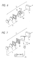
- Fig. 7 is a schematic view showing principal part of the fifth embodiment of the present invention.
- the same reference numerals in Fig. 7 denote the same parts as in Fig. 1.
- the difference from the first embodiment described above is that a light quantity detection means for detecting the light quantities (intensities) of a plurality of light beams is inserted between the polarization limiting means and the deflection means, and feedback control is made based on the signals detected by the light quantity detection means, thereby suppressing variations in light quantity of the plurality of light beams.
- Other arrangements and optical effects are substantially the same as those in the first embodiment described above, thereby obtaining the same effect.
- a light quantity detection means 70 comprises a half mirror 71 inserted in the optical path between the polarizer 10 and the cylindrical lens 5, and a light quantity sensor 72 for detecting the light quantity of a light beam reflected by the half mirror 71.
- the light-emitting portions (light-emitting points) of the surface-emission laser 1 are caused to flicker in turn, and some light components of a light beam emitted by each light-emitting portion are reflected by the half mirror 71 via the collimator lens 2, aperture 3, and polarizer 10 to be guided toward the light quantity sensor 72.
- the light quantity sensor 72 detects the light quantity of each light beam.
- a laser drive circuit 73 serving as a control means individually controls the light-emission intensities of the plurality of light-emitting portions based on the signals obtained by the light quantity sensor 72, so that the light quantities of the plurality of light beams equal a predetermined quantity. With this control, variations in light quantity of the plurality of light beams can be suppressed, thus obtaining high-quality line images.
- the polarization limiting means for limiting the directions of polarization of a plurality of light beams is inserted in the optical path between the light source means and the deflection means, the reflectances, transmittances, and the like of optical elements after the polarization limiting means can have equal characteristics with respect to the plurality of light beams, thus achieving an optical scanning device that can eliminate light quantity differences in units of beam spots.
- the directions of polarization of light beams emitted by the plurality of light-emitting portions are limited to a substantially 45° direction with respect to the main scanning direction, an optical scanning device that can obtain both p- and s-polarized light components can be achieved.
- the control means controls the light source means on the basis of the detected values obtained from the light quantity detection means so that the plurality of light beams that have passed through the polarization limiting means have equal intensities, variations in light quantity of the plurality of light beams can be suppressed, thus achieving an optical scanning device that can obtain high-quality line images.
Landscapes
- Physics & Mathematics (AREA)
- Optics & Photonics (AREA)
- Engineering & Computer Science (AREA)
- General Physics & Mathematics (AREA)
- Multimedia (AREA)
- Signal Processing (AREA)
- General Engineering & Computer Science (AREA)
- Theoretical Computer Science (AREA)
- Facsimile Scanning Arrangements (AREA)
- Mechanical Optical Scanning Systems (AREA)
Claims (13)
- Dispositif de balayage optique comprenant :dans lequelun moyen formant source de lumière (1) ayant une pluralité de parties émettant de la lumière ;un moyen de déviation (6) pour dévier une pluralité de faisceaux lumineux émis par ledit moyen formant source de lumière (1) ;un moyen optique (11) pour guider la pluralité de faisceaux lumineux émis par ledit moyen formant source de lumière (1) vers ledit moyen de déviation (6) ;un moyen de formation d'image (7) pour guider la pluralité de faisceaux lumineux déviés par ledit moyen de déviation (6) vers une surface à balayer ;
la pluralité de faisceaux lumineux émis par ledit moyen formant source de lumière (1) ont des directions de polarisation différentes ; et
le dispositif de balayage optique comprend en outre un moyen de mise en concordance des directions de polarisation, disposé sur le chemin optique entre ledit moyen formant source de lumière (1) et ledit moyen de déviation (6), pour faire en sorte que les différentes directions de polarisation de la pluralité de faisceaux lumineux émis par ledit moyen formant source de lumière (1) concordent les unes avec les autres. - Dispositif selon la revendication 1, dans lequel :ledit moyen de mise en concordance des directions de polarisation est disposé sur le chemin optique entre une ouverture (3) et ledit moyen de déviation (6).
- Dispositif selon l'une quelconque des revendications précédentes, dans lequel ledit moyen de mise en concordance des directions de polarisation est formé de façon solidaire d'un élément optique (40) qui fait partie dudit moyen optique (11).
- Dispositif selon l'une quelconque des revendications précédentes, dans lequel ledit moyen de mise en concordance des directions de polarisation est maintenu de façon pivotante par un élément de maintien.
- Dispositif selon l'une quelconque des revendications précédentes, dans lequel :ledit moyen formant source de lumière (1) est commandé par un moyen de commande (13) afin que les intensités de la pluralité de faisceaux lumineux ayant passé à travers ledit moyen de mise en concordance des directions de polarisation correspondent les unes aux autres.
- Dispositif selon l'une quelconque des revendications précédentes, dans lequel :les intensités de la pluralité de faisceaux lumineux émis par ledit moyen formant source de lumière (1) sont détectées par des moyens de détection de quantité de lumière (70) sur un chemin optique entre ledit moyen de mise en concordance des directions de polarisation et ledit moyen de déviation (6).
- Dispositif selon la revendication 6, dans lequel :ledit moyen formant source de lumière (1) est commandé par un moyen de commande (73) en fonction de valeurs détectées obtenues par ledit moyen de détection de quantité de lumière (70) afin que les intensités de la pluralité de faisceaux lumineux ayant passé à travers ledit moyen de mise en concordance des directions de polarisation correspondent les unes aux autres.
- Dispositif selon l'une quelconque des revendications précédentes, dans lequel :la pluralité de faisceaux lumineux émis par ladite pluralité de parties émettant de la lumière sont respectivement polarisés dans une direction sensiblement égale à 45° par rapport à une direction de balayage principale.
- Dispositif selon l'une quelconque des revendications précédentes, dans lequel :ledit moyen de mise en concordance des directions de polarisation est incliné par rapport à un axe optique dudit moyen optique (11).
- Dispositif selon l'une quelconque des revendications précédentes, dans lequel :ledit moyen formant source de lumière (1) comprend un élément laser multi-faisceaux monolithique constitué d'un laser à émission de surface.
- Dispositif selon l'une quelconque des revendications précédentes, dans lequel :ledit moyen de mise en concordance des directions de polarisation comprend un polariseur.
- Dispositif selon l'une quelconque des revendications précédentes, dans lequel :ledit moyen optique (11) comporte une lentille de collimation (2) et une lentille cylindrique (5).
- Imprimante à faisceau laser, comprenant :un dispositif selon l'une quelconque des revendications précédentes, etun support d'enregistrement.
Applications Claiming Priority (3)
| Application Number | Priority Date | Filing Date | Title |
|---|---|---|---|
| JP8124020A JPH09288244A (ja) | 1996-04-22 | 1996-04-22 | 光走査装置 |
| JP124020/96 | 1996-04-22 | ||
| JP12402096 | 1996-04-22 |
Publications (3)
| Publication Number | Publication Date |
|---|---|
| EP0804015A2 EP0804015A2 (fr) | 1997-10-29 |
| EP0804015A3 EP0804015A3 (fr) | 1997-11-05 |
| EP0804015B1 true EP0804015B1 (fr) | 2003-01-22 |
Family
ID=14875051
Family Applications (1)
| Application Number | Title | Priority Date | Filing Date |
|---|---|---|---|
| EP97106632A Expired - Lifetime EP0804015B1 (fr) | 1996-04-22 | 1997-04-22 | Dispositif de balayage optique |
Country Status (5)
| Country | Link |
|---|---|
| US (1) | US5991063A (fr) |
| EP (1) | EP0804015B1 (fr) |
| JP (1) | JPH09288244A (fr) |
| KR (1) | KR100264761B1 (fr) |
| DE (1) | DE69718549T2 (fr) |
Families Citing this family (21)
| Publication number | Priority date | Publication date | Assignee | Title |
|---|---|---|---|---|
| US6992690B2 (en) * | 1998-09-14 | 2006-01-31 | Canon Kabushiki Kaisha | Multi-beam scanning apparatus |
| JP2001080116A (ja) * | 1999-09-14 | 2001-03-27 | Fujitsu Ltd | 光学ユニット及びその製造方法、並びに、電子写真式記録装置 |
| JP2001337285A (ja) | 2000-05-29 | 2001-12-07 | Minolta Co Ltd | 光走査装置 |
| JP4708637B2 (ja) | 2000-09-29 | 2011-06-22 | キヤノン株式会社 | マルチビーム走査光学装置及びそれを用いた画像形成装置 |
| KR100452852B1 (ko) * | 2002-01-09 | 2004-10-14 | 삼성전자주식회사 | 확대 광학계 및 그것을 갖는 화상형성 장치 |
| JP2004302063A (ja) * | 2003-03-31 | 2004-10-28 | Fuji Photo Optical Co Ltd | レーザアレイ結像レンズおよびこれを用いた画像形成装置 |
| US6847389B2 (en) | 2003-05-02 | 2005-01-25 | Kabushiki Kaisha Toshiba | Optical beam scanning device and image forming apparatus |
| JP2005017896A (ja) * | 2003-06-27 | 2005-01-20 | Canon Inc | 光走査装置及びそれを用いた画像形成装置 |
| US8549226B2 (en) | 2004-05-14 | 2013-10-01 | Hewlett-Packard Development Company, L.P. | Providing an alternative caching scheme at the storage area network level |
| US7271942B2 (en) * | 2004-06-02 | 2007-09-18 | Canon Kabushiki Kaisha | Multi-beam optical scanning apparatus and image forming apparatus using the same |
| JP4500738B2 (ja) * | 2005-06-20 | 2010-07-14 | 株式会社リコー | 光走査装置・画像形成装置 |
| US7817176B2 (en) | 2005-12-26 | 2010-10-19 | Ricoh Company, Ltd. | Light source device, optical scanning device, and image forming apparatus |
| JP4965860B2 (ja) * | 2006-01-18 | 2012-07-04 | キヤノン株式会社 | 光学走査装置 |
| JP4849613B2 (ja) * | 2006-10-25 | 2012-01-11 | 株式会社リコー | 光走査装置及び画像形成装置 |
| JP4849618B2 (ja) * | 2006-11-24 | 2012-01-11 | 株式会社リコー | 光走査装置及び画像形成装置 |
| KR100866393B1 (ko) * | 2006-12-15 | 2008-11-03 | 경상대학교산학협력단 | 평면 스캔 입자화상속도계 기법 |
| KR101111904B1 (ko) * | 2007-02-06 | 2012-03-14 | 삼성전자주식회사 | 광주사유니트 및 이를 채용한 화상형성장치 |
| JP2009020203A (ja) | 2007-07-10 | 2009-01-29 | Ricoh Co Ltd | 光走査装置及び画像形成装置 |
| JP2009157014A (ja) | 2007-12-26 | 2009-07-16 | Ricoh Co Ltd | 光走査装置及び画像形成装置 |
| JP5006810B2 (ja) | 2008-02-06 | 2012-08-22 | 株式会社リコー | 光走査装置及び画像形成装置 |
| JP6071038B2 (ja) * | 2012-09-14 | 2017-02-01 | 株式会社リコー | 光走査装置および画像形成装置 |
Family Cites Families (11)
| Publication number | Priority date | Publication date | Assignee | Title |
|---|---|---|---|---|
| JPS61118716A (ja) * | 1984-11-14 | 1986-06-06 | Minolta Camera Co Ltd | 光量調節装置 |
| JPS62227667A (ja) * | 1986-03-31 | 1987-10-06 | Canon Inc | レ−ザ駆動制御装置 |
| JPS6350811A (ja) * | 1986-08-21 | 1988-03-03 | Minolta Camera Co Ltd | レ−ザ−ビ−ムプリンタ |
| US5233188A (en) * | 1989-04-03 | 1993-08-03 | Hitachi, Ltd. | Laser beam scanning apparatus for scanning a laser beam obtained by composing a plurality of beams |
| JPH0368915A (ja) * | 1989-08-08 | 1991-03-25 | Nec Corp | 光アイソレータおよび光アイソレータ内蔵半導体レーザモジュール |
| JPH04355986A (ja) * | 1990-06-26 | 1992-12-09 | Canon Inc | 光源駆動装置及びこの光源駆動装置を使用する装置 |
| US5295148A (en) * | 1990-09-12 | 1994-03-15 | Seiko Epson Corporation | Surface emission type semiconductor laser |
| DE69212285T2 (de) * | 1991-05-14 | 1997-02-06 | Seiko Epson Corp., Tokio/Tokyo | Bilderzeugungsvorrichtung |
| US5371526A (en) * | 1992-09-22 | 1994-12-06 | Xerox Corporation | Raster output scanner for a single pass printing system which separates plural laser beams by wavelength and polarization |
| US5276463A (en) * | 1992-09-22 | 1994-01-04 | Xerox Corporation | Raster output scanning arrangement for a printing machine |
| JP3549666B2 (ja) * | 1996-04-03 | 2004-08-04 | 株式会社リコー | マルチビーム書込光学系 |
-
1996
- 1996-04-22 JP JP8124020A patent/JPH09288244A/ja active Pending
-
1997
- 1997-04-22 KR KR1019970014918A patent/KR100264761B1/ko not_active Expired - Fee Related
- 1997-04-22 EP EP97106632A patent/EP0804015B1/fr not_active Expired - Lifetime
- 1997-04-22 DE DE69718549T patent/DE69718549T2/de not_active Expired - Lifetime
- 1997-04-22 US US08/844,873 patent/US5991063A/en not_active Expired - Lifetime
Also Published As
| Publication number | Publication date |
|---|---|
| EP0804015A3 (fr) | 1997-11-05 |
| KR100264761B1 (ko) | 2000-09-01 |
| US5991063A (en) | 1999-11-23 |
| KR970071356A (ko) | 1997-11-07 |
| JPH09288244A (ja) | 1997-11-04 |
| DE69718549D1 (de) | 2003-02-27 |
| EP0804015A2 (fr) | 1997-10-29 |
| DE69718549T2 (de) | 2003-10-02 |
Similar Documents
| Publication | Publication Date | Title |
|---|---|---|
| EP0804015B1 (fr) | Dispositif de balayage optique | |
| US8085457B2 (en) | Light source system, optical scanner, image forming apparatus, and light-amount control method | |
| US7667868B2 (en) | Optical scanning device and image forming apparatus | |
| US4547038A (en) | Apparatus for scanning a plane with light beams | |
| US6133935A (en) | Optical scanning apparatus | |
| US5844707A (en) | Scanning optical device | |
| JP3549666B2 (ja) | マルチビーム書込光学系 | |
| US8837027B2 (en) | Optical scanning device and image forming apparatus | |
| EP1035730A2 (fr) | Appareil optique de balayage à plusieurs faisceaux et appareil de formation d'images en couleurs | |
| JP3334447B2 (ja) | 光走査装置の光軸調整方法、光軸調整装置、及び光走査装置 | |
| JPH09179048A (ja) | マルチビーム走査光学装置およびレーザ光源装置 | |
| US20040145644A1 (en) | Multi-beam scanning device and image forming apparatus using the scanning device | |
| US6963433B2 (en) | Multibeam scanning optical device and image forming apparatus using the same | |
| KR19980019037A (ko) | 멀티-빔 주사장치(multi-beam scanning apparatus with controlled scan line bow) | |
| US5438450A (en) | Optical scanning apparatus | |
| KR101111904B1 (ko) | 광주사유니트 및 이를 채용한 화상형성장치 | |
| JP4817668B2 (ja) | 光走査装置 | |
| JPH04321370A (ja) | 走査光学装置 | |
| JP3308342B2 (ja) | 半導体レーザアレイ光源装置 | |
| JPH04242215A (ja) | 光走査装置 | |
| JP2004126482A (ja) | マルチビーム光源装置およびマルチビーム走査装置 | |
| JP2000292722A (ja) | マルチビーム光走査装置 | |
| JPH1164759A (ja) | 光走査光学装置 | |
| JPH0980334A (ja) | 走査光学装置 | |
| JP2002258186A (ja) | 光源装置 |
Legal Events
| Date | Code | Title | Description |
|---|---|---|---|
| PUAI | Public reference made under article 153(3) epc to a published international application that has entered the european phase |
Free format text: ORIGINAL CODE: 0009012 |
|
| PUAL | Search report despatched |
Free format text: ORIGINAL CODE: 0009013 |
|
| AK | Designated contracting states |
Kind code of ref document: A2 Designated state(s): DE FR GB |
|
| AK | Designated contracting states |
Kind code of ref document: A3 Designated state(s): DE FR GB |
|
| 17P | Request for examination filed |
Effective date: 19980504 |
|
| 17Q | First examination report despatched |
Effective date: 20010523 |
|
| GRAG | Despatch of communication of intention to grant |
Free format text: ORIGINAL CODE: EPIDOS AGRA |
|
| GRAG | Despatch of communication of intention to grant |
Free format text: ORIGINAL CODE: EPIDOS AGRA |
|
| GRAH | Despatch of communication of intention to grant a patent |
Free format text: ORIGINAL CODE: EPIDOS IGRA |
|
| GRAH | Despatch of communication of intention to grant a patent |
Free format text: ORIGINAL CODE: EPIDOS IGRA |
|
| GRAA | (expected) grant |
Free format text: ORIGINAL CODE: 0009210 |
|
| AK | Designated contracting states |
Kind code of ref document: B1 Designated state(s): DE FR GB |
|
| REG | Reference to a national code |
Ref country code: GB Ref legal event code: FG4D |
|
| REF | Corresponds to: |
Ref document number: 69718549 Country of ref document: DE Date of ref document: 20030227 Kind code of ref document: P |
|
| ET | Fr: translation filed | ||
| PLBE | No opposition filed within time limit |
Free format text: ORIGINAL CODE: 0009261 |
|
| STAA | Information on the status of an ep patent application or granted ep patent |
Free format text: STATUS: NO OPPOSITION FILED WITHIN TIME LIMIT |
|
| 26N | No opposition filed |
Effective date: 20031023 |
|
| PGFP | Annual fee paid to national office [announced via postgrant information from national office to epo] |
Ref country code: FR Payment date: 20090424 Year of fee payment: 13 |
|
| REG | Reference to a national code |
Ref country code: FR Ref legal event code: ST Effective date: 20101230 |
|
| PG25 | Lapsed in a contracting state [announced via postgrant information from national office to epo] |
Ref country code: FR Free format text: LAPSE BECAUSE OF NON-PAYMENT OF DUE FEES Effective date: 20100430 |
|
| PGFP | Annual fee paid to national office [announced via postgrant information from national office to epo] |
Ref country code: GB Payment date: 20140414 Year of fee payment: 18 |
|
| PGFP | Annual fee paid to national office [announced via postgrant information from national office to epo] |
Ref country code: DE Payment date: 20140430 Year of fee payment: 18 |
|
| REG | Reference to a national code |
Ref country code: DE Ref legal event code: R119 Ref document number: 69718549 Country of ref document: DE |
|
| GBPC | Gb: european patent ceased through non-payment of renewal fee |
Effective date: 20150422 |
|
| PG25 | Lapsed in a contracting state [announced via postgrant information from national office to epo] |
Ref country code: DE Free format text: LAPSE BECAUSE OF NON-PAYMENT OF DUE FEES Effective date: 20151103 Ref country code: GB Free format text: LAPSE BECAUSE OF NON-PAYMENT OF DUE FEES Effective date: 20150422 |