EP1661753A2 - Kopfstütze - Google Patents
Kopfstütze Download PDFInfo
- Publication number
- EP1661753A2 EP1661753A2 EP05257257A EP05257257A EP1661753A2 EP 1661753 A2 EP1661753 A2 EP 1661753A2 EP 05257257 A EP05257257 A EP 05257257A EP 05257257 A EP05257257 A EP 05257257A EP 1661753 A2 EP1661753 A2 EP 1661753A2
- Authority
- EP
- European Patent Office
- Prior art keywords
- head
- moving mechanism
- passenger
- controller
- drive motor
- Prior art date
- Legal status (The legal status is an assumption and is not a legal conclusion. Google has not performed a legal analysis and makes no representation as to the accuracy of the status listed.)
- Granted
Links
- 230000007246 mechanism Effects 0.000 claims abstract description 41
- 238000000034 method Methods 0.000 description 20
- 230000000977 initiatory effect Effects 0.000 description 9
- 239000000463 material Substances 0.000 description 4
- 230000005540 biological transmission Effects 0.000 description 3
- 239000011347 resin Substances 0.000 description 3
- 229920005989 resin Polymers 0.000 description 3
- JOYRKODLDBILNP-UHFFFAOYSA-N Ethyl urethane Chemical compound CCOC(N)=O JOYRKODLDBILNP-UHFFFAOYSA-N 0.000 description 2
- 206010071366 Post-traumatic neck syndrome Diseases 0.000 description 2
- 208000021567 Whiplash injury Diseases 0.000 description 2
- 238000010586 diagram Methods 0.000 description 2
- 239000004744 fabric Substances 0.000 description 2
- 239000006260 foam Substances 0.000 description 2
- 239000010985 leather Substances 0.000 description 2
- 230000003247 decreasing effect Effects 0.000 description 1
- 238000012986 modification Methods 0.000 description 1
- 230000004048 modification Effects 0.000 description 1
- 230000000153 supplemental effect Effects 0.000 description 1
Images


Classifications
-
- B—PERFORMING OPERATIONS; TRANSPORTING
- B60—VEHICLES IN GENERAL
- B60N—SEATS SPECIALLY ADAPTED FOR VEHICLES; VEHICLE PASSENGER ACCOMMODATION NOT OTHERWISE PROVIDED FOR
- B60N2/00—Seats specially adapted for vehicles; Arrangement or mounting of seats in vehicles
- B60N2/80—Head-rests
- B60N2/806—Head-rests movable or adjustable
- B60N2/838—Tiltable
- B60N2/862—Tiltable with means for maintaining a desired position when the seat-back is adjusted, e.g. parallelogram mechanisms
-
- B—PERFORMING OPERATIONS; TRANSPORTING
- B60—VEHICLES IN GENERAL
- B60N—SEATS SPECIALLY ADAPTED FOR VEHICLES; VEHICLE PASSENGER ACCOMMODATION NOT OTHERWISE PROVIDED FOR
- B60N2/00—Seats specially adapted for vehicles; Arrangement or mounting of seats in vehicles
- B60N2/80—Head-rests
- B60N2/888—Head-rests with arrangements for protecting against abnormal g-forces, e.g. by displacement of the head-rest
Definitions
- the present invention relates to head rests of vehicle seats. More particularly, the present invention relates to head rests of vehicle seats that can increase restraint performance for heads of passengers when a vehicle collision is sensed or predicted.
- a head rest of a vehicle seat that can increase restraint performance for a head of a passenger when a vehicle collision is sensed or predicted is already known.
- Such a head rest (an active head rest) is taught, for example, by Japanese Laid-Open Patent Publication Number 11-334439.
- a head rest main body is arranged and constructed to be tilted or inclined.
- the head rest main body is tilted, based on a signal from the sensor, so as to move toward the passenger head.
- the head rest main body moves closer to the passenger head so that the passenger head can be reliably supported by the head rest main body.
- the passenger can be prevented from suffering a whiplash injury.
- the head position of the passenger sitting on the vehicle seat differs somewhat depending on the body type and the body size of the passenger. Therefore, in the known head rest, the head rest main body is not always appropriately positioned relative to the passenger head. That is, the head rest main body cannot be previously adjusted so as to be appropriately adjacent to and aligned with the passenger head. In addition, during a vehicle collision, the head rest main body is tilted over a predetermined angle range regardless of the body type and the body size of the passenger. Consequently, when a vehicle actually collides, often times, the passenger head cannot be suitably held by the tilted head rest main body. This means that the passenger cannot be sufficiently prevented from suffering a whiplash injury.
- one object of the present invention to provide improved head rests for a vehicle, in particular, to provide head rests that can achieve a good holding performance when the vehicle is applied with an impact.
- a head rest of a vehicle seat may include a head support portion for supporting a head of a passenger, and a drive unit for moving the head support portion.
- the drive unit has a moving mechanism that is arranged and constructed to move the head support portion toward and away from the passenger head, an actuator for actuating the moving mechanism, a load detecting device that can detect a load applied to the actuator and generate a control signal representative of the detected load, and a controller that can control the actuator so as to control the moving mechanism.
- the controller controls the moving mechanism so as to move the head support portion toward the passenger head.
- the controller controls the moving mechanism based on the control signal so as to stop the motion of the head support portion.
- the head support portion can be easily positioned in an optimal position relative to the passenger head without utilizing detectors that can detect when the head support portion contacts or comes closer to a passenger head. Therefore, the passenger head can be suitably held by the head support portion when a vehicle collides.
- the head support portion is moved away from the passenger head over a desired distance after the head support portion is stopped.
- the head support portion can be prevented from pressing the passenger head. Therefore, the passenger can normally be prevented from suffering discomfort.
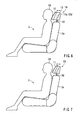
- a representative head rest 1 (an active head rest) includes a main body 10 and a pair of head rest stays 20 coupled to the main body 10.
- the head rest stays 20 are vertically movably connected to a seat back 3a of a vehicle seat 3 so that the head rest 1 (the main body 10) is movably attached to the seat back 3a.
- the main body 10 is composed of two portions, i.e., a relatively immovable rear portion 12 (i.e., a base portion or a first portion) that is coupled to the head rest stays 20, and a movable front portion 11 (i.e., a head support portion or a second portion) that can support a head 50 of a passenger sitting on the vehicle seat 3.
- the head rest stays 20 are connected to a known vertical moving mechanism (not shown) that is disposed or embedded in the seat back 3a. Therefore, the head rest stays 20 can vertically move relative to the seat back 3a upon actuation of the vertical moving mechanism so that the height of the head rest main body 10 can be vertically changed or adjusted in order to correspond to the passenger head 50.
- the rear portion 12 includes a plate-shaped rear brackets 12a, a rear shell 12c having a rear cushion pad 12b, and rear side shield members 12d that are integrally provided to the rear bracket 12a.
- the rear bracket 12a may preferably be made from resins.
- the rear bracket 12a is secured to the head rest stays 20.
- the rear shell 12c is attached to the rear bracket 12a while interleaving the rear cushion pad 12b.
- the rear shell 12c may preferably be made from leather, cloth or other such materials.
- the rear cushion pad 12b may preferably be made from urethane foam or other such materials.
- the front portion 11 includes a plate-shaped front bracket 11a, a front shell 11c having a front cushion pad 11b, and front side shield members 11d that are integrally provided to the front bracket 11a.
- the front bracket 11a may preferably be made from resins.
- the front shell 11c is attached to the front bracket 11a while interleaving the front cushion pad 11b.
- the front shell 11c may preferably be made from leather, cloth or other such materials.
- the front cushion pad 11b is made from urethane foam or other such materials.
- the main body 10 additionally includes a cover sheet 13 that is overlaid on the front and rear side shield members 11d and 12d.
- the cover sheet 13 may preferably be formed from a resin film.
- the front and rear side shield members 11d and 12d, and the cover sheet 13 may function to conceal a moving mechanism 33 (which will be described hereinafter) that is disposed between the front and rear portions 11 and 12.
- the head rest 1 further includes a drive unit 30 for moving the front portion 11 relative to the rear portion 12.
- the drive unit 30 is composed of a linking mechanism or a moving mechanism 33, an actuator 34, a load sensor 35 (i.e., a load detecting device or a supplemental detecting device), and a controller 36.
- the moving mechanism 33 interconnects the front and rear brackets 11a and 12a of the front and rear portion 11 and 12 such that the front bracket 11a (the front portion 11) can move vertically and back and forth (i.e., horizontally) relative to the rear bracket 12a (the rear portion 12).
- the actuator 34 has a drive motor 34a (i.e., a drive source) for actuating the moving mechanism 33.
- the load sensor 35 can detect a load that is applied to the drive motor 34a and generate a signal (i.e., a control signal) representative of the detected load.
- the load sensor 35 may preferably be a rotational speed sensor for detecting a rotational speed of the drive motor 34a.
- the load applied to the drive motor 34a can be detected by detecting changes in the rotational speed of the drive motor 34a because the drive motor rotational speed may decrease as the load increases.
- the controller 36 can control the actuator 34 (the drive motor 34a) based on the signal generated by the load sensor 35, thereby controlling the motion of the moving mechanism 33.
- the moving mechanism 33 of the drive unit 30 essentially consists of a rear vertical base plate 33a2, a front vertical base plate 33a1, and a pair of cross bar links 33b.
- the rear vertical base plate 33a2 is connected to the rear bracket 12a of the rear portion 12.
- the rear base plate 33a2 has side folded portions 33a2' that are folded forwardly in parallel.
- the lower portions of the side folded portions 33a2' are respectively formed with vertically extending lower guide slots 33d2 that are laterally aligned with each other.
- the front vertical base plate 33a1 is connected to the front bracket 11 a of the front portion 11.
- the front base plate 33a1 has side folded portions 33a1' that are folded rearwardly in parallel.
- the upper portions of the side folded portions 33a1' are formed with vertically extending upper guide slots 33d1 that are laterally aligned with each other.
- each of the cross bar links 33b is composed of outer and inner cross bars 33b2 and 33b1 (i.e., first and second cross bars) that are rotatably interconnected via pivot pin 40.
- the outer cross bars 33b2 of the respective pairs of cross bar links 33b are rotatably interconnected at their rear and front end portions (i.e., first and second end portions) via a first connector shaft 42 and a second connector shaft 41.
- the rear end portions of the outer cross bars 33b2 thus connected are respectively rotatably and slidably engaged with the lower guide slots 33d2 formed in the rear base plate 33a2 via guide pins 33c2.
- the front end portions of the outer cross bars 33b2 thus connected are respectively rotatably and slidably engaged with the upper guide slots 33d1 formed in the front base plate 33a1 via guide pins 33c1.
- the rear end portions of the inner cross bars 33b 1 are respectively rotatably connected to the upper portions of the side folded portions 33a2' of the rear base plate 33a2 via pivot pins 44.
- the front end portions of the inner cross bars 33b 1 are respectively rotatably connected to the lower portions of the side folded portions 33a1' of the front base plate 33a1 via pivot pins 43.
- the front and rear base plates 33a1 and 33a2 are relatively operably connected via the moving mechanism 33.
- the front and rear brackets 11a and 12a are relatively operably connected via the moving mechanism 33.
- the rear end portions (first end portions) of the outer cross bars 33b2 can vertically move relative to the lower portions of the rear base plate 33a2.
- the front end portions (second end portions) of the outer cross bars 33b2 can vertically move relative to the upper portions of the front base plate 33a1.
- the rear end portions (first end portions) of the inner cross bars 33b1 can simply rotate relative to the upper portions of the rear base plate 33a2.
- the front end portions (second end portions) of the inner cross bars 33b1 can simply rotate relative to the lower portions of the rear front plate 33a1.
- the drive motor 34a of the actuator 34 is attached to the rear base plate 33a2.
- the drive motor 34a thus disposed is coupled to the first connector shaft 42 via a power transmission rod 45 so as to vertically move the first connector shaft 42.
- the actuator motor 34a is electrically communicated with the controller 36.
- the controller 36 is electrically communicated with the load sensor 35.
- the controller 36 is connected to a sensor S (i.e., a main detecting device).
- the sensor S senses that a passenger sits on the vehicle seat and generates a representative signal (i.e., an initiation signal).
- the representative signal is transmitted to the controller 36 so that the actuator drive motor 34a is actuated based on the signal, thereby moving the moving mechanism 33. That is, the moving mechanism 33 can be arranged and constructed to be operated when a passenger sits on the vehicle seat.
- a seatbelt switch may preferably be used as the sensor S (the main detecting device). Therefore, an on-off signal of the seatbelt switch may preferably be used as the initiation signal.
- the moving mechanism 33 is in an initial condition or retracted condition.
- the outer and inner cross bars 33b2 and 33b1 of the cross bar links 33b are in a folded condition.
- the outer cross bars 33b2 are substantially vertically positioned so that the first connector shaft 42 (and the guide pins 33c2) is positioned at the lowermost position within the lower guide slots 33d2 formed in the rear base plate 33a2.
- the inner cross bars 33b1 are substantially vertically positioned so that the second connector shaft 41 (and the guide pins 33c1) is positioned at the uppermost position within the upper guide slots 33d1 formed in the front base plate 33a1.
- the representative signal (the initiation signal) is transmitted to the controller 36
- the controller 36 actuates the actuator drive motor 34a based on the transmitted signal so that the power transmission rod 45 is shifted upwardly.
- the first connector shaft 42 connected to the power transmission rod 45 is lifted upwardly.
- the guide pins 33c2 (the first connector shaft 42) move upwardly along the lower guide slots 33d2.
- the guide pins 33c1 (the second connector shaft 41) move downwardly along the upper guide slots 33d1. Consequently, the outer cross bars 33b2 rotate counterclockwise about the first connector shaft 42 (the guide pins 33c2) while moving upwardly.
- the inner cross bars 33b1 rotate clockwise around the pivot pins 44.
- the outer and inner cross bars 33b2 and 33b1 of the cross bar links 33b can move toward an unfolded condition shown by a solid line in FIG. 2.
- the moving mechanism 33 can be shifted toward an extended condition (which corresponds to a position shown by solid lines in FIG. 2) from a retracted condition (which corresponds to a position shown by brokens line in FIG. 2).
- the front base plate 33a1 moves from a normal position (which corresponds to a position shown by broken lines in FIG. 2) toward a projected position (which corresponds to a position shown by solid lines in FIG. 2).
- the front base plate 33a1 moves forwardly and upwardly relative to the rear base plate 33a2. Consequently, as shown by broken lines in FIG. 2, the front portion 11 of the head rest main body 10 is projected forwardly and upwardly relative to the rear portion 12 of the head rest main body 10 toward the passenger head 50. In other words, the front portion 11 is projected forwardly and upwardly relative to the seat back 3a of the vehicle seat 3.
- the load applied to the drive motor 34a is increased so that the rotational speed of the drive motor 34a may be decreased.
- the load sensor 35 detects the changes of the rotational speed of the drive motor 34a and transmits the control signal to the controller 36. Based on the control signal, the controller 36 stops the drive motor 34a and actuates the drive motor 34a in a reverse direction, thereby appropriately controlling the moving mechanism 33 such that the front portion 11 is moved away from the passenger head 50 for some distance.
- the front portion 11 of the head rest main body 10 is positioned in an optimal position relative to the passenger head 50 (FTG.7) such that the passenger head 50 can be effectively protected if the vehicle actually collides.
- the controlling process by the controller 36 is started when the ignition switch is turned on. Also, the controlling process is repeated in a desired time interval.
- a reference F3 corresponds to a flag showing as to whether the rotational speed of the drive motor 34a is not greater than R2 (i.e., as to whether the load is applied to the drive motor 34a upon contacting of the front portion 11 and the passenger head 50).
- each of the flags F1-F4 has a default value of zero (0) when the ignition switch is turned on.
- step S 1 the controller 36 determines if the initiation signal from the sensor S (an ON signal of the seatbelt switch) is transmitted to the controller 36 (i.e., if the passenger sits on the vehicle seat and fastens a seatbelt).
- step S1 if the initiation signal from the sensor S is not transmitted to the controller 36, the controlling process by the controller 36 is terminated and returned to an initial state (step S1) after the values of F1-F4 are cleared to 0 in step S 17. Thus, the controlling process by the controller 36 is restarted.
- step S2 the controller 36 determines if the drive motor 34a is rotating (i.e., if the value of F1 is 1).
- step S2 if the drive motor 34a is not rotating, in step S3 the controller 36 changes the value of F1 from 0 to 1. Thereafter, in step S4 the drive motor 34a is rotated in a normal direction. When the drive motor 34a is rotating, in step S5 the controller 36 determines if the rotational speed of the drive motor 34a is not less than R1 (i.e., if the value of F2 is 1).
- step S5 if the rotational speed of the drive motor 34a does not reach to R1, in step S6 the controller 36 determines if the rotational speed of the drive motor 34a is not less than R1. In step S6, when the rotational speed of the drive motor 34a reaches to R1 the controller 36 changes the value of F2 from 0 to 1 in step S7. Thereafter, in step S8 the controller 36 determines if the rotational speed of the drive motor 34a is not greater than R2 (i.e., if the value of F3 is 1). Further, in step S6, if the rotational speed of the drive motor 34a still does not reach to R1, the controlling process by the controller 36 is terminated and returned to an initial state (step S1) so that a new controlling process is started. As will be recognized, when the controlling process by the controller 36 is returned from step S6 to step S1, the new controlling process advances from step S1 to step S5 via step S2 without passing through steps S3 and S4 because the value of F1 is changed to 1.
- step S8 if the rotational speed of the drive motor 34a is greater than R2, in step S9 the controller 36 further determines if the rotational speed of the drive motor 34a is not greater than R2. In step S9, if the rotational speed of the drive motor 34a is not greater than R2, the controller 36 changes the value of F3 from 0 to 1 in step S 10. At the same time, in step S 11 the drive motor 34a is stopped and the timer is actuated in order to determine the time that has elapsed after the drive motor 34a is stopped. Thereafter, in step S12 the controller 36 determines if the elapsed time after stopping of the drive motor 34a is greater than T (i.e., if the value of F4 is 1).
- step S9 if the rotational speed of the drive motor 34a does not still reach to R2, the controlling process by the controller 36 is terminated and returned to an initial state (step S1) so that a new controlling process is started.
- step S1 the new process advances from step S1 to step S8 via steps S2 and S5 without passing through steps S3, S4, S6 and S7 because each of the values of F1 and F2 is changed to 1.
- step S12 if the time measured by the timer is not greater than T, in step S 13 the controller 36 determines if the time measured by the timer is greater than T. In step S 13, if the time measured by the timer is greater than T, the controller 36 changes the value of F4 from 0 to 1 in step S 14. Thereafter, in step S 15 the drive motor 34a is rotated in the reverse direction so as to move the front portion 11 away from the passenger head 50. Thereafter, in step S16 the drive motor 34a is stopped when a predetermined time has elapsed after the drive motor 34a is rotated in the reverse direction.
- step S 13 if the time measured by the timer is still not greater than T, the controlling process by the controller 36 is terminated and returned to an initial state (step S1) so that a new controlling process is started.
- the new process advances from step S1 to step S12 via steps S2, S5 and S8 without passing through steps S3, S4, S6, S7 and S9-S11 because each of the values of F1-F3 is changed to 1.
- the front portion 11 of the head rest main body 10 can be easily positioned in an optimal position relative to the passenger head 50 without utilizing proximity detectors (e.g., contact or non-contact type detectors) that can detect when the front portion 11 contacts or comes closer to the passenger head 50 and generate representative signals. Also, the front portion 11 can be effectively prevented from excessively projecting forwardly toward the passenger head 50. Therefore, the front portion 11 can be prevented from pressing against the passenger head 50.
- proximity detectors e.g., contact or non-contact type detectors
- the rotational speed sensor for detecting the rotational speed of the drive motor 34a is used as the load sensor 35 (the load detecting device)
- various types of sensors can be used as the load sensor 35.
- the load sensor 35 may includes a torque sensor, a current sensor, and a voltage sensor for the drive motor 34a.
- the seatbelt switch is used as the sensor S.
- a special switch can be additionally provided so that the front portion 11 can be moved by operating the switch, if required.
- the moving mechanisms 33 is arranged and constructed to be operated when the passenger sits on the vehicle seat.
- the moving mechanism 33 can be arranged and constructed to be operated when a vehicle collision is sensed or predicted.
- a sensor for predicting the vehicle collision or a sensor for sensing the vehicle collision may preferably be used as the sensor S (the main sensing device) so that a signal from such a sensor can be used as the initiation signal instead of the on-off signal of the seatbelt switch. Therefore, in the step S1 in FIG. 5, the controller 36 determines as to whether a vehicle collision is sensed or predicted.
- the optimal position of the front portion 11 of the head rest main body 10 corresponds to the position shown in FIG. 7.
- the optimal position is not limited to such a position. In other words, the optimal position of the front portion 11 can be appropriately changed, if necessary.
- the drive motor 34a (the drive source) of the actuator 34 includes, for example, but is not limited to, a DC motor, an AC motor, a pulse motor, a linear motor or other such motors.
- the drive motor 34a can be replaced with a hydraulic or pneumatic device (e.g., a hydraulic cylinder), if necessary.
- a drive source that is susceptible to the load applied thereto is more suitable.
Landscapes
- Engineering & Computer Science (AREA)
- Aviation & Aerospace Engineering (AREA)
- Transportation (AREA)
- Mechanical Engineering (AREA)
- Seats For Vehicles (AREA)
- Chair Legs, Seat Parts, And Backrests (AREA)
Applications Claiming Priority (1)
| Application Number | Priority Date | Filing Date | Title |
|---|---|---|---|
| JP2004342561A JP4436238B2 (ja) | 2004-11-26 | 2004-11-26 | ヘッドレスト |
Publications (3)
| Publication Number | Publication Date |
|---|---|
| EP1661753A2 true EP1661753A2 (de) | 2006-05-31 |
| EP1661753A3 EP1661753A3 (de) | 2009-12-02 |
| EP1661753B1 EP1661753B1 (de) | 2011-03-30 |
Family
ID=36097341
Family Applications (1)
| Application Number | Title | Priority Date | Filing Date |
|---|---|---|---|
| EP05257257A Ceased EP1661753B1 (de) | 2004-11-26 | 2005-11-25 | Kopfstütze |
Country Status (4)
| Country | Link |
|---|---|
| US (1) | US7717507B2 (de) |
| EP (1) | EP1661753B1 (de) |
| JP (1) | JP4436238B2 (de) |
| DE (1) | DE602005027159D1 (de) |
Cited By (4)
| Publication number | Priority date | Publication date | Assignee | Title |
|---|---|---|---|---|
| EP1880895A1 (de) * | 2006-07-20 | 2008-01-23 | Centre d'Etudes et Recherche pour l'Automobile ( CERA) | Kopfstütze eines Kraftfahrzeugsitzes die, im Fall eines Aufpralls vor- und aufwärts bewegbar ist |
| EP2106963A1 (de) * | 2008-04-04 | 2009-10-07 | Batz, S.Coop. | Kopfstütze für einen Kraftfahrzeugsitz |
| DE102019211773A1 (de) * | 2019-08-06 | 2021-02-11 | Brose Fahrzeugteile SE & Co. Kommanditgesellschaft, Coburg | Kopfstütze mit Scherenkinematik |
| US12059989B2 (en) | 2020-03-11 | 2024-08-13 | Brose Fahrzeugteile SE & Co. Kommanditgesellschaft, Coburg | Headrest with an adjustment device |
Families Citing this family (38)
| Publication number | Priority date | Publication date | Assignee | Title |
|---|---|---|---|---|
| JP4436238B2 (ja) * | 2004-11-26 | 2010-03-24 | トヨタ紡織株式会社 | ヘッドレスト |
| US7963598B2 (en) * | 2004-12-09 | 2011-06-21 | Toyota Boshoku Kabushiki Kaisha | Head rest control systems |
| DE102005002464B4 (de) * | 2005-01-18 | 2009-04-02 | Autoliv Development Ab | Sicherheitsanordnung |
| JP4690085B2 (ja) * | 2005-03-23 | 2011-06-01 | アイシン精機株式会社 | ヘッドレスト |
| JP4294629B2 (ja) * | 2005-10-17 | 2009-07-15 | アイシン精機株式会社 | ヘッドレスト装置 |
| JP4647559B2 (ja) * | 2006-07-27 | 2011-03-09 | トヨタ紡織株式会社 | アクティブヘッドレスト |
| KR100811005B1 (ko) | 2006-08-29 | 2008-03-07 | 최은혁 | 자동차용 슬라이드형 헤드레스트 |
| EP2058168B1 (de) * | 2006-08-31 | 2011-06-01 | Toyota Boshoku Kabushiki Kaisha | Sitz für fahrzeug |
| JP4306751B2 (ja) * | 2007-03-15 | 2009-08-05 | トヨタ自動車株式会社 | ヘッドレスト制御装置及びアクティブヘッドレスト |
| US7992933B2 (en) * | 2007-06-21 | 2011-08-09 | Lear Corporation | Integrated vehicle seat with active head restraint system |
| US7798570B2 (en) * | 2007-07-05 | 2010-09-21 | E & E Manufacturing Company, Inc. | Adjustable headrest for a vehicle seat |
| DE102007041496B3 (de) * | 2007-08-31 | 2009-02-26 | Johnson Controls Gmbh | Kopfstütze für ein Fahrzeug |
| JP5252182B2 (ja) * | 2008-02-13 | 2013-07-31 | アイシン精機株式会社 | シートの制御システム |
| US8100472B2 (en) * | 2008-03-17 | 2012-01-24 | Lear Corporation | Vehicle active head restraint system with a locking linkage |
| US8205941B2 (en) | 2008-07-30 | 2012-06-26 | Trw Vehicle Safety Systems Inc. | Active head restraint for a vehicle seat |
| JP4981837B2 (ja) * | 2009-04-13 | 2012-07-25 | 三菱電機株式会社 | 車両用乗員保護装置 |
| WO2012111097A1 (ja) * | 2011-02-15 | 2012-08-23 | トヨタ自動車株式会社 | 車両用ヘッドレスト装置 |
| US8696065B2 (en) | 2012-01-05 | 2014-04-15 | Be Aerospace, Inc. | Adjustable headrest for an aircraft seat |
| US8899685B2 (en) | 2012-06-27 | 2014-12-02 | Porter Group, Llc | Vehicle seat headrest assembly having vertical and longitudinal adjustment |
| CN107901807B (zh) * | 2012-09-26 | 2020-04-24 | 提爱思科技股份有限公司 | 头枕 |
| WO2014049730A1 (ja) * | 2012-09-26 | 2014-04-03 | テイ・エス テック株式会社 | ヘッドレスト |
| CN104736386A (zh) * | 2012-09-26 | 2015-06-24 | 提爱思科技股份有限公司 | 头枕 |
| KR101428285B1 (ko) * | 2012-12-12 | 2014-08-08 | 현대자동차주식회사 | 리어시트용 헤드레스트의 리클라이닝 장치 |
| KR101483866B1 (ko) | 2013-07-04 | 2015-01-19 | 현대다이모스(주) | 시트 헤드레스트 |
| KR101576377B1 (ko) * | 2014-07-01 | 2015-12-11 | 현대다이모스(주) | 헤드레스트 리클라이닝 모듈 |
| KR101601535B1 (ko) * | 2014-11-12 | 2016-03-09 | 현대자동차주식회사 | 헤드레스트 장치 |
| KR101585850B1 (ko) * | 2015-02-27 | 2016-01-15 | (주)현대기업 | 파워 헤드레스트 장치 |
| US9987958B2 (en) * | 2015-10-26 | 2018-06-05 | Ford Global Technologies, Llc | Quick disconnect headrest |
| KR101736831B1 (ko) | 2015-12-21 | 2017-05-18 | 현대다이모스(주) | 전동식 헤드레스트 |
| EP3423301B1 (de) * | 2016-02-29 | 2020-04-08 | Jifeng Automotive Interior GmbH | Kopfstütze mit verbesserter verstelleinrichtung |
| EP3315355B1 (de) * | 2016-10-26 | 2021-12-08 | Volvo Car Corporation | Fahrzeugsitz und kopfstütze für einen fahrzeugsitz |
| US10099591B2 (en) * | 2016-12-01 | 2018-10-16 | David Flynn | Dual configuration headrest system |
| JP6879864B2 (ja) | 2017-08-25 | 2021-06-02 | 日本発條株式会社 | ヘッドレスト装置 |
| DE102018109611B4 (de) * | 2018-04-10 | 2022-04-21 | Grammer Aktiengesellschaft | Kopfstütze |
| US10953810B2 (en) * | 2018-11-01 | 2021-03-23 | Safran Seats Usa Llc | Impact bracket stress-deformation release mechanism |
| KR102362526B1 (ko) * | 2020-10-26 | 2022-02-18 | 대원강업주식회사 | 넥 서포트형 액티브 헤드레스트 |
| CN114801933B (zh) * | 2021-08-26 | 2023-04-07 | 延锋国际座椅系统有限公司 | 一种座椅电动头枕 |
| KR20250082019A (ko) * | 2023-11-28 | 2025-06-09 | 현대자동차주식회사 | 자동차용 헤드레스트 위치 조절 장치 |
Citations (2)
| Publication number | Priority date | Publication date | Assignee | Title |
|---|---|---|---|---|
| JPH11334439A (ja) | 1998-05-27 | 1999-12-07 | Mazda Motor Corp | 車両用乗員保護装置 |
| US20050280304A1 (en) | 2004-06-16 | 2005-12-22 | Fumitoshi Akaike | Head rests |
Family Cites Families (27)
| Publication number | Priority date | Publication date | Assignee | Title |
|---|---|---|---|---|
| GB2194729B (en) * | 1986-09-04 | 1990-03-14 | Gen Motors Corp | Improved vehicle headrest |
| DE3719809C1 (de) | 1987-06-13 | 1988-06-09 | Daimler Benz Ag | Stautopf fuer Kraftstoffbehaelter |
| JPS6411512A (en) * | 1987-07-06 | 1989-01-17 | Aisin Seiki | Headrest driving apparatus |
| JP2665983B2 (ja) | 1989-11-30 | 1997-10-22 | 株式会社タチエス | ヘッドレスト制御方法およびヘッドレスト制御装置 |
| US5020855A (en) * | 1990-02-09 | 1991-06-04 | Prince Corporation | Adjustable headrest |
| US5694320A (en) * | 1995-06-07 | 1997-12-02 | Automotive Technologies Intl, Inc. | Rear impact occupant protection apparatus |
| US6746078B2 (en) * | 1997-12-17 | 2004-06-08 | Automotive Technologies International, Inc. | System and method for moving a headrest based on anticipatory sensing |
| US6088640A (en) * | 1997-12-17 | 2000-07-11 | Automotive Technologies International, Inc. | Apparatus for determining the location of a head of an occupant in the presence of objects that obscure the head |
| US5822707A (en) * | 1992-05-05 | 1998-10-13 | Automotive Technologies International, Inc. | Automatic vehicle seat adjuster |
| JPH0767744A (ja) | 1993-08-31 | 1995-03-14 | Nisshin Plant Co Ltd | 車両用自動可動ヘッドレスト |
| JPH08187139A (ja) | 1995-01-06 | 1996-07-23 | Nec Home Electron Ltd | 車載ヘッドレスト装置 |
| DE19707998B4 (de) * | 1997-02-27 | 2007-04-05 | Inova Gmbh Technische Entwicklungen | Kraftfahrzeugsitz |
| US6196579B1 (en) * | 1998-09-24 | 2001-03-06 | Trw Vehicle Safety Systems Inc. | Rear impact occupant protection system |
| JP3829517B2 (ja) | 1999-02-16 | 2006-10-04 | マツダ株式会社 | 車両用乗員保護装置 |
| DE19916804C1 (de) * | 1999-04-14 | 2000-08-10 | Bayerische Motoren Werke Ag | Vorrichtung zum Justieren einer Fahrzeugkopfstütze sowie ein Verfahren unter Verwendung einer derartigen Vorrichtung |
| US6213548B1 (en) * | 1999-08-12 | 2001-04-10 | Trw Inc. | Head restraint apparatus |
| US6607242B2 (en) * | 2000-12-13 | 2003-08-19 | Lear Corporation | Head restraint assembly |
| JP2004518575A (ja) * | 2001-02-24 | 2004-06-24 | カイペル ゲーエムベーハー アンド カンパニー カーゲー | 車両座席用の頭部拘束具 |
| US7145263B2 (en) * | 2001-10-30 | 2006-12-05 | Lear Corporation | Automatic headrest adjustment control system for a vehicle seat assembly |
| JP3915648B2 (ja) | 2002-09-30 | 2007-05-16 | トヨタ自動車株式会社 | 車両の乗員保護装置 |
| JP4425215B2 (ja) * | 2002-12-21 | 2010-03-03 | カイペル ゲーエムベーハー アンド カンパニー カーゲー | 衝突作動式ヘッドレスト |
| DE10325472A1 (de) * | 2003-06-05 | 2004-12-30 | Keiper Gmbh & Co. Kg | Crashaktive Kopfstütze |
| WO2005073019A1 (ja) * | 2004-01-30 | 2005-08-11 | Toyota Boshoku Kabushiki Kaisha | ヘッドレスト制御装置およびアクティブヘッドレスト |
| DE102004017688B4 (de) * | 2004-04-10 | 2010-02-11 | Itw Automotive Products Gmbh & Co. Kg | Kopfstütze für Automobilsitze |
| JP4436238B2 (ja) * | 2004-11-26 | 2010-03-24 | トヨタ紡織株式会社 | ヘッドレスト |
| JP4690085B2 (ja) * | 2005-03-23 | 2011-06-01 | アイシン精機株式会社 | ヘッドレスト |
| US20070246989A1 (en) * | 2006-04-21 | 2007-10-25 | Brockman Mark A | Adjustable headrest |
-
2004
- 2004-11-26 JP JP2004342561A patent/JP4436238B2/ja not_active Expired - Fee Related
-
2005
- 2005-11-22 US US11/285,770 patent/US7717507B2/en not_active Expired - Fee Related
- 2005-11-25 EP EP05257257A patent/EP1661753B1/de not_active Ceased
- 2005-11-25 DE DE602005027159T patent/DE602005027159D1/de not_active Expired - Lifetime
Patent Citations (2)
| Publication number | Priority date | Publication date | Assignee | Title |
|---|---|---|---|---|
| JPH11334439A (ja) | 1998-05-27 | 1999-12-07 | Mazda Motor Corp | 車両用乗員保護装置 |
| US20050280304A1 (en) | 2004-06-16 | 2005-12-22 | Fumitoshi Akaike | Head rests |
Cited By (6)
| Publication number | Priority date | Publication date | Assignee | Title |
|---|---|---|---|---|
| EP1880895A1 (de) * | 2006-07-20 | 2008-01-23 | Centre d'Etudes et Recherche pour l'Automobile ( CERA) | Kopfstütze eines Kraftfahrzeugsitzes die, im Fall eines Aufpralls vor- und aufwärts bewegbar ist |
| FR2903941A1 (fr) * | 2006-07-20 | 2008-01-25 | Cera | Appui-tete de siege de vehicule automobile deplacable vers l'avant et vers le haut en cas de choc |
| EP2106963A1 (de) * | 2008-04-04 | 2009-10-07 | Batz, S.Coop. | Kopfstütze für einen Kraftfahrzeugsitz |
| DE102019211773A1 (de) * | 2019-08-06 | 2021-02-11 | Brose Fahrzeugteile SE & Co. Kommanditgesellschaft, Coburg | Kopfstütze mit Scherenkinematik |
| DE102019211773B4 (de) | 2019-08-06 | 2023-03-16 | Brose Fahrzeugteile SE & Co. Kommanditgesellschaft, Coburg | Kopfstütze für einen Fahrzeugsitz und Fahrzeugsitz |
| US12059989B2 (en) | 2020-03-11 | 2024-08-13 | Brose Fahrzeugteile SE & Co. Kommanditgesellschaft, Coburg | Headrest with an adjustment device |
Also Published As
| Publication number | Publication date |
|---|---|
| JP4436238B2 (ja) | 2010-03-24 |
| DE602005027159D1 (de) | 2011-05-12 |
| JP2006151111A (ja) | 2006-06-15 |
| US7717507B2 (en) | 2010-05-18 |
| US20060279114A1 (en) | 2006-12-14 |
| EP1661753B1 (de) | 2011-03-30 |
| EP1661753A3 (de) | 2009-12-02 |
Similar Documents
| Publication | Publication Date | Title |
|---|---|---|
| EP1661753B1 (de) | Kopfstütze | |
| US7484797B2 (en) | Head rests | |
| US7073856B2 (en) | Head rests | |
| JP4754354B2 (ja) | ヘッドレスト制御装置 | |
| US6666292B2 (en) | Seat occupant restraint system for vehicle | |
| EP1029736B1 (de) | Insassenschutzvorrichtung für Fahrzeuge | |
| GB2383530A (en) | Automatic headrest adjustment using sensors | |
| JP7056508B2 (ja) | 車両の乗員保護装置 | |
| EP1218226B1 (de) | Airbagsteuersystem | |
| EP1518743A1 (de) | Fahrzeugsitz | |
| US20090062989A1 (en) | Seat device for vehicle | |
| JP2004352037A (ja) | 後席用エアバッグ装置 | |
| US6000717A (en) | Vehicle occupant protection apparatus | |
| US7350860B2 (en) | Headrest apparatus | |
| JP2548485B2 (ja) | 車両用シートの安全装置 | |
| JP3147759B2 (ja) | 車両用シート | |
| JPH07117600A (ja) | 後席エアバッグ装置 | |
| JP3084084B2 (ja) | 自動車のエアバッグ装置 | |
| JP3829474B2 (ja) | 車両用乗員保護装置 | |
| JP2000203369A (ja) | 車両用シ―ト | |
| JP3135604B2 (ja) | 自動車のエアバッグ装置 | |
| JPH0516759A (ja) | 自動車のエアバツグ装置 | |
| JP3105022B2 (ja) | 自動車のエアバッグ装置 | |
| CN116279270B (zh) | 气囊组件、车辆及气囊控制方法 | |
| JP2573451B2 (ja) | 車両用シートの安全装置 |
Legal Events
| Date | Code | Title | Description |
|---|---|---|---|
| PUAI | Public reference made under article 153(3) epc to a published international application that has entered the european phase |
Free format text: ORIGINAL CODE: 0009012 |
|
| AK | Designated contracting states |
Kind code of ref document: A2 Designated state(s): AT BE BG CH CY CZ DE DK EE ES FI FR GB GR HU IE IS IT LI LT LU LV MC NL PL PT RO SE SI SK TR |
|
| AX | Request for extension of the european patent |
Extension state: AL BA HR MK YU |
|
| RAP1 | Party data changed (applicant data changed or rights of an application transferred) |
Owner name: TOYOTA JIDOSHA KABUSHIKI KAISHA Owner name: TOYOTA BOSHOKU KABUSHIKI KAISHA |
|
| PUAL | Search report despatched |
Free format text: ORIGINAL CODE: 0009013 |
|
| AK | Designated contracting states |
Kind code of ref document: A3 Designated state(s): AT BE BG CH CY CZ DE DK EE ES FI FR GB GR HU IE IS IT LI LT LU LV MC NL PL PT RO SE SI SK TR |
|
| AX | Request for extension of the european patent |
Extension state: AL BA HR MK YU |
|
| 17P | Request for examination filed |
Effective date: 20100510 |
|
| AKX | Designation fees paid |
Designated state(s): DE |
|
| R17P | Request for examination filed (corrected) |
Effective date: 20100510 |
|
| GRAP | Despatch of communication of intention to grant a patent |
Free format text: ORIGINAL CODE: EPIDOSNIGR1 |
|
| GRAS | Grant fee paid |
Free format text: ORIGINAL CODE: EPIDOSNIGR3 |
|
| GRAA | (expected) grant |
Free format text: ORIGINAL CODE: 0009210 |
|
| AK | Designated contracting states |
Kind code of ref document: B1 Designated state(s): DE |
|
| REF | Corresponds to: |
Ref document number: 602005027159 Country of ref document: DE Date of ref document: 20110512 Kind code of ref document: P |
|
| REG | Reference to a national code |
Ref country code: DE Ref legal event code: R096 Ref document number: 602005027159 Country of ref document: DE Effective date: 20110512 |
|
| PLBE | No opposition filed within time limit |
Free format text: ORIGINAL CODE: 0009261 |
|
| STAA | Information on the status of an ep patent application or granted ep patent |
Free format text: STATUS: NO OPPOSITION FILED WITHIN TIME LIMIT |
|
| 26N | No opposition filed |
Effective date: 20120102 |
|
| REG | Reference to a national code |
Ref country code: DE Ref legal event code: R097 Ref document number: 602005027159 Country of ref document: DE Effective date: 20120102 |
|
| REG | Reference to a national code |
Ref country code: DE Ref legal event code: R079 Ref document number: 602005027159 Country of ref document: DE Free format text: PREVIOUS MAIN CLASS: B60N0002480000 Ipc: B60N0002800000 |
|
| PGFP | Annual fee paid to national office [announced via postgrant information from national office to epo] |
Ref country code: DE Payment date: 20181113 Year of fee payment: 14 |
|
| REG | Reference to a national code |
Ref country code: DE Ref legal event code: R119 Ref document number: 602005027159 Country of ref document: DE |
|
| PG25 | Lapsed in a contracting state [announced via postgrant information from national office to epo] |
Ref country code: DE Free format text: LAPSE BECAUSE OF NON-PAYMENT OF DUE FEES Effective date: 20200603 |