EP1553360B1 - Air conditioning equipment - Google Patents
Air conditioning equipment Download PDFInfo
- Publication number
- EP1553360B1 EP1553360B1 EP03799088.4A EP03799088A EP1553360B1 EP 1553360 B1 EP1553360 B1 EP 1553360B1 EP 03799088 A EP03799088 A EP 03799088A EP 1553360 B1 EP1553360 B1 EP 1553360B1
- Authority
- EP
- European Patent Office
- Prior art keywords
- air
- fan
- small holes
- duct
- conditioning equipment
- Prior art date
- Legal status (The legal status is an assumption and is not a legal conclusion. Google has not performed a legal analysis and makes no representation as to the accuracy of the status listed.)
- Expired - Lifetime
Links
Images


Classifications
-
- F—MECHANICAL ENGINEERING; LIGHTING; HEATING; WEAPONS; BLASTING
- F04—POSITIVE - DISPLACEMENT MACHINES FOR LIQUIDS; PUMPS FOR LIQUIDS OR ELASTIC FLUIDS
- F04D—NON-POSITIVE-DISPLACEMENT PUMPS
- F04D29/00—Details, component parts, or accessories
- F04D29/66—Combating cavitation, whirls, noise, vibration or the like; Balancing
- F04D29/661—Combating cavitation, whirls, noise, vibration or the like; Balancing especially adapted for elastic fluid pumps
-
- F—MECHANICAL ENGINEERING; LIGHTING; HEATING; WEAPONS; BLASTING
- F24—HEATING; RANGES; VENTILATING
- F24F—AIR-CONDITIONING; AIR-HUMIDIFICATION; VENTILATION; USE OF AIR CURRENTS FOR SCREENING
- F24F1/00—Room units for air-conditioning, e.g. separate or self-contained units or units receiving primary air from a central station
- F24F1/0007—Indoor units, e.g. fan coil units
- F24F1/0043—Indoor units, e.g. fan coil units characterised by mounting arrangements
- F24F1/0047—Indoor units, e.g. fan coil units characterised by mounting arrangements mounted in the ceiling or at the ceiling
-
- F—MECHANICAL ENGINEERING; LIGHTING; HEATING; WEAPONS; BLASTING
- F24—HEATING; RANGES; VENTILATING
- F24F—AIR-CONDITIONING; AIR-HUMIDIFICATION; VENTILATION; USE OF AIR CURRENTS FOR SCREENING
- F24F1/00—Room units for air-conditioning, e.g. separate or self-contained units or units receiving primary air from a central station
- F24F1/0007—Indoor units, e.g. fan coil units
- F24F1/0068—Indoor units, e.g. fan coil units characterised by the arrangement of refrigerant piping outside the heat exchanger within the unit casing
-
- F—MECHANICAL ENGINEERING; LIGHTING; HEATING; WEAPONS; BLASTING
- F24—HEATING; RANGES; VENTILATING
- F24F—AIR-CONDITIONING; AIR-HUMIDIFICATION; VENTILATION; USE OF AIR CURRENTS FOR SCREENING
- F24F13/00—Details common to, or for air-conditioning, air-humidification, ventilation or use of air currents for screening
- F24F13/24—Means for preventing or suppressing noise
-
- F—MECHANICAL ENGINEERING; LIGHTING; HEATING; WEAPONS; BLASTING
- F24—HEATING; RANGES; VENTILATING
- F24F—AIR-CONDITIONING; AIR-HUMIDIFICATION; VENTILATION; USE OF AIR CURRENTS FOR SCREENING
- F24F1/00—Room units for air-conditioning, e.g. separate or self-contained units or units receiving primary air from a central station
- F24F1/0007—Indoor units, e.g. fan coil units
- F24F1/0018—Indoor units, e.g. fan coil units characterised by fans
- F24F1/0022—Centrifugal or radial fans
-
- F—MECHANICAL ENGINEERING; LIGHTING; HEATING; WEAPONS; BLASTING
- F25—REFRIGERATION OR COOLING; COMBINED HEATING AND REFRIGERATION SYSTEMS; HEAT PUMP SYSTEMS; MANUFACTURE OR STORAGE OF ICE; LIQUEFACTION SOLIDIFICATION OF GASES
- F25B—REFRIGERATION MACHINES, PLANTS OR SYSTEMS; COMBINED HEATING AND REFRIGERATION SYSTEMS; HEAT PUMP SYSTEMS
- F25B2500/00—Problems to be solved
- F25B2500/12—Sound
-
- F—MECHANICAL ENGINEERING; LIGHTING; HEATING; WEAPONS; BLASTING
- F25—REFRIGERATION OR COOLING; COMBINED HEATING AND REFRIGERATION SYSTEMS; HEAT PUMP SYSTEMS; MANUFACTURE OR STORAGE OF ICE; LIQUEFACTION SOLIDIFICATION OF GASES
- F25B—REFRIGERATION MACHINES, PLANTS OR SYSTEMS; COMBINED HEATING AND REFRIGERATION SYSTEMS; HEAT PUMP SYSTEMS
- F25B41/00—Fluid-circulation arrangements
Definitions
- the present invention relates to air conditioning equipment.
- noise is a collection of acoustic waves of various frequencies. Acoustic waves advance through the fan duct, reflecting on the duct wall. The sound absorption materials contain a lot of foam. Acoustic waves enter the sound absorption materials, while advancing through the fan duct, and cause diffuse reflection by the foam effect inside the sound absorption materials. As a result, the energy of the acoustic waves is converted into thermal energy whereby the energy level drops. In other words, the noise level drops. This explains the mechanism of noise reduction by sound absorption materials.
- the Helmholtz resonator is formed to include an opening inside a fan duct and space inside the resonator. With such construction, acoustic waves propagating through the fan duct enter the Helmholtz resonator where they resonate. Resonance causes the energy of acoustic waves to change to thermal energy. Thus, the noise level drops.
- the resonant wavelength of an acoustic wave is determined by the size of the entrance and the inner size of the resonator. In addition, it is only the acoustic wave whose frequency is high and near resonant frequency that is allowed to reduce the noise level.
- the method using resonance is a noise reduction method using a perforated acoustic board that is provided with a perforated plate that is exposed on the inner surface of a duct and a back layer at the back thereof.
- This is a method of noise reduction by making acoustic waves resonate by a resonator that is formed by the perforated plate and the back layer.
- the principle and effect of this method are the same as those of the Helmholtz resonator.
- the frequency of absorbing sound depends on the diameter of the perforated plate, the thickness of the back layer, the open area ratio, and the board thickness. Therefore, low frequency noise can also be reduced depending on the design. This, however, requires a back layer of reasonable size. In addition, quite a large space is required for installation.
- Japanese Unexamined Patent Publication No. 7-247905 discloses an embodiment of funning air to an air duct through a perforated plate. This is directed to reducing noise by funning air to the air duct so as to lower the temperature of the air of the air duct, thereby making acoustic waves to resonate with the perforated plate and the back layer thereof. Accordingly, this is entirely different in principles, actions and effects from the present invention.
- Japanese Unexamined Patent Publication No. 8-143149 discloses an embodiment of exhausting air through a porous member of airflow resistance, which is attached to an exhaust hole. This is directed to reducing the sound of fluid jet by expanding an area to which the fluid jet blows so as to drop the fluid speed. Accordingly, this is entirely different in principles, actions and effects from the present invention, either.
- Another problem is posed with reference to noise generated by a fan blade or a fan that propagates to both directions, to the blow side and the suction side.
- a separate noise reduction mechanism is required on each side, which will make the structure complicated and require quite a large space for installation.
- the present invention is directed to solving the aforementioned problems. It is an object to provide air conditioning equipment, fan equipment, and a method of reducing noise of equipment that allow sufficient reduction effects of low frequency noise at a few hundred hertz or below.
- Another object of the present invention is to provide air conditioning equipment, fan equipment, and a method of reducing noise of equipment that allow reducing low frequency noise in a wide frequency range.
- Another object is to provide air conditioning equipment, fan equipment, and a method of reducing noise of equipment that do not require large space.
- Another object is to provide air conditioning equipment, fan equipment, and a method of reducing noise of equipment of simple structure that use small space for installation by reducing noise in both directions, to the blow side and the suction side of a fan blade or fan based on one method of noise reduction.
- Another object is to provide a low cost system that is structured so that when the rotational speed of the fan blade or fan equipment is changed, the frequency range or the acoustic pressure level in which the noise reduction can effect automatically changes in accordance with the rotational speed changed, by using a pressure difference between before and after a fan blade or fan equipment as a drive source.
- Another object is to provide a method of reducing pressure pulsation that does not require large space.
- JP 58-195908 U shows a system for conducting a fluid, the system having a plurality of channels having a plurality of valves.
- JP 2002-250535 A discloses an air conditioning indoor unit comprising a heat exchanger, a fan and a fan stabilizer comprising at its tip a plurality of holes, the heat exchanger, the fan and the fan stabilizer being disposed within a housing.
- Air conditioning equipment is characterized by including a heat ex-changer that exchanges heat between refrigerant of a refrigeration cycle and air; a fan that fans air to the heat ex-changer; an air duct in which the fan is installed and through which an acoustic wave propagates; and a plurality of small holes that blows a jet to the air duct, and sucking a jet from the air duct according to a pressure difference between a blow side and a suction side of the fan.
- the air conditioning equipment according to this invention is characterized in that the blow side and the suction side of the fan is separated by a solid wall, and the plurality of small holes is provided on the solid wall.
- the air conditioning equipment according to this invention is characterized in that the air conditioning equipment is a ceiling cassette type air conditioner, and the plurality of small holes is provided on a decorative panel.
- the air conditioning equipment may be characterized by including a first air duct in which the fan and the heat exchanger are installed; a plurality of small holes provided on at least one of the wall of any position on the blow side of the fan and a wall of any position on the suction side of the fan; and a second air duct linking one of the plurality of small holes and another of the plurality of small holes or linking the plurality of small holes and an opposite side to the suction side or the blow side of the fan on which the plurality of small holes is provided.
- the air conditioning equipment may be characterized by including a first air duct in which the fan and the heat exchanger are installed; a large number of small holes provided on one of the wall of any position of the blow side of the fan and a wall of any position of the suction side of the fan; a small number of big diameter holes provided on the other of the wall of the any position on the blow side of the fan and the wall of the any position on the suction side of the fan; and a second air duct linking the large number of small holes and the small number of big diameter holes.
- the air conditioning equipment according to this invention may be characterized by including a plurality of small ducts installed on the blow side of the fan, the plurality of small ducts including the large number of small holes.
- the air conditioning equipment according to this invention is characterized in that the plurality of small holes or the large number of small holes are provided in any position near the fan.
- the air conditioning equipment according to this invention may be characterized in that the second air duct is installed outside the first air duct.
- the air conditioning equipment according to this invention may be characterized in that the second air duct is installed inside the first air duct.
- the air conditioning equipment according to this invention may be characterized in that the air conditioning equipment is an air conditioning outdoor unit, the air conditioning outdoor unit includes a compressor in a housing, and an acoustic wave from the compressor propagates through the air duct.
- the air conditioning equipment according to this invention may be characterized in that a diameter of each of the small holes is up to 10mm.
- the air conditioning equipment according to this invention may be characterized in that an open area ratio of the small holes is up to 10% where the open area ratio is a ratio of a total cross-sectional area of the small holes to a cross-sectional area of the wall of the air duct.
- a fan equipment may include a fan blade that fans air; an air duct in which the fan blade is in-stalled and through which an acoustic wave propagates; and a plurality of small holes that blows a jet to the air duct and sucking a jet from the air duct according to a pressure difference between a blow side and a suction side of the fan blade.
- the fan equipment may have a first air duct in which the fan blade is installed; a plurality of small holes provided on at least one of the wall of any position on the blow side of the fan blade and a wall of any position on the suction side of the fan blade; and a second air duct linking one of the plurality of small holes and another of the plurality of small holes or linking the plurality of small holes and an opposite side to the suction side or the blow side of the fan blade on which the plurality of small holes is provided.
- the fan equipment may comprise a first air duct in which the fan blade is installed; a large number of small holes provided on one of the wall of any position of the blow side of the fan blade and a wall of any position of the suction side of the fan blade; a small number of big diameter holes provided on the other of the wall of the any position on the blow side of the fan blade and the wall of the any position on the suction side of the fan blade; and a second air duct linking the large number of small holes and the small number of big diameter holes.
- the small holes may be provided in a position near the fan blade.
- the second air duct may be installed outside the first air duct.
- the second air duct may be installed inside the first air duct.
- the fan equipment may include a fan blade that fans air; an air duct in which the fan blade is installed and a distance between a blow side of the fan blade and an exit of the air duct is substantially long; and a plurality of small holes provided on a wall near the blow side of the fan blade.
- the fan equipment may include a fan blade that fans air; an air duct in which the fan blade is installed and a distance between a suction side of the fan blade and an entrance of the air duct is substantially long; and a plurality of small holes provided on a wall near the suction side of the fan blade.
- the fan equipment may have a fan blade that fans air: an air duct in which the fan blade is installed and through which an acoustic wave propagates; and a flow-channel separator installed on at least one of a blow side and a suction side of the fan blade, the flow-channel separator including a plurality of small holes, and the flow-channel separator formed in contact with the air duct on an upstream side and formed so that air blows through a narrow flow channel on a downstream side.
- the fan equipment may include a fan blade that fans air: an air duct in which the fan blade is installed and through which an acoustic wave propagates; and a flow-channel separator installed on at least one of a blow side and a suction side of the fan blade, the flow-channel separator including a plurality of small holes, and formed in contact with the air duct on an downstream side and open on an upstream side.
- a diameter of each of the small holes may be up to 10mm.
- an open area ratio of the small holes may be up to 10% where the open area ratio is a ratio of a total cross-sectional area of the small holes to a cross-sectional area of the wall of the air duct.
- a noise reduction method of equipment is used in equipment in which a fan that funs air to an air duct is installed.
- the noise reduction method is characterized by including blowing a jet to the air duct through a plurality of small holes according to a pressure difference that is one of between a blow side and a suction side of the fan and between the blow side or the suction side of the fan and outside the air duct; and sucking in a jet from the air duct according to the pressure difference.
- a pressure pulsation reduction equipment of refrigeration cycle equipment may include a refrigeration cycle including a compressor; and a pressure pulsation reducer, which is installed on at lease one of a high pressure side and a low pressure side of the refrigeration cycle, the pressure pulsation reducer including a flow-channel separator with a plurality of small holes, and the flow-channel separator formed open on one end and in contact with a flow-channel wall on the other end.
- the pressure pulsation reduction equipment of refrigeration cycle equipment may include a pressure pulsation reducer, which is installed on at lease one of a discharge side and a suction side of the compressor, the pressure pulsation reducer including a flow-channel separator with a plurality of small holes, and the flow-channel separator formed open on one end and in contact with a flow-channel wall on the other end.
- the pressure pulsation reduction equipment of refrigeration cycle equipment may include a pressure pulsation reducer, which is installed in an oil separator that is incorporated with the compressor, the pressure pulsation reducer including a flow-channel separator with a plurality of small holes, and the flow-channel separator formed open on one end and in contact with the oil separator on the other end.
- the pressure pulsation reduction equipment of refrigeration cycle equipment may include a refrigeration cycle including a compressor; and a pressure pulsation reducer including a plurality of small holes provided on pipeline walls on a discharge side and a suction side of the compressor, the plurality of small holes on the discharged side of the compressor and the plurality of small holes on the suction side of the compressor linked by a connection pipe.
- a diameter of each small hole of the plurality of small holes may be up to 10mm.
- an open area ratio of the plurality of small holes may be up to 10% where the open area ratio is a ratio of a total cross-sectional area of the plurality of small holes to a cross-sectional area of the flow-channel wall.
- a pressure pulsation reduction equipment of pump equipment may include a pressure pulsation reducer, which is installed on at least one of a discharge side and a suction side of the pump equipment, the pressure pulsation reducer including a flow-channel separator with a plurality of small holes in a flow channel of a medium, and the flow-channel separator formed open on one end and in contact with a flow-channel wall on the other end.
- the pressure pulsation reduction equipment of pump equipment may include a pres-sure pulsation reducer including a plurality of small holes provided on pipe-line walls on a discharge side and a suction side of the pump equipment, the plurality of small holes on the discharge side of the pump equipment and the plurality of small holes on the suction side of the pump equipment linked by a connection pipe.
- a pres-sure pulsation reducer including a plurality of small holes provided on pipe-line walls on a discharge side and a suction side of the pump equipment, the plurality of small holes on the discharge side of the pump equipment and the plurality of small holes on the suction side of the pump equipment linked by a connection pipe.
- a diameter of each of the small holes may be up to 10mm.
- an open area ratio of the plurality of small holes may be up to 10% where the open area ratio is a ratio of a total cross-sectional area of the plurality of small holes to a cross-sectional area of the flow-channel wall.
- a pressure pulsation reduction method of equipment may be used in equipment in which one of a compressor and pump equipment discharging a medium to a medium flow channel is in-stalled.
- the pressure pulsation reduction method may include the steps of blowing a jet to the medium flow channel through a plurality of small holes according to one of a pressure difference between a discharge side and a suction side of the one of a compressor and pump equipment and a pressure difference that occurs in the medium flow channel of the one of the compressor and the pump equipment; and sucking in a jet from the medium flow channel according to the one of the pressure differences.
- Fig. 1 is a diagram of a first embodiment.
- Fig. 1(a) is a block diagram of air conditioning equipment illustrating a noise reduction method.
- Fig. 1(b) is an enlarged diagram showing a vicinity of small holes.
- the air conditioning equipment shown in the figures is a ceiling cassette type indoor unit.
- a housing 3 contains a fan 1 and a heat exchanger 2.
- Inlet air 5 that is sucked in through an air inlet passes through a filter 8 and a guide 4 towards a suction side of the fan 1.
- Outlet air 6 is blown out from the fan 1 in various directions by a louver 7.
- Small holes 9 are formed on a decorative panel so as to link the air outlet and the air inlet.
- the inlet air 5 is sucked in through the air inlet to the housing 3 by the induction effect of the fan 1 and then supplied to the heat exchanger 2 through the filter 8. Then, the inlet air 5 is heated in a heating operation and cooled in a cooling operation in the heat exchanger 2, and then blown out from the housing 3 to the room as the outlet air 6.
- noises by different generation mechanisms occur such as motor sound produced by a motor to drive the fan 1; hissing sound produced by rotary vanes of the fan 1 cutting the air and interference sound produced by airflow generated by one vane interfering another vane of the fan 1; scraping sound of airflow produced by passage of air through the air duct and the heat exchanger 2, cylinder group generating sound produced by a group of pipelines and edge tone produced by projections; and jet flow sound produced by air blowing from the air outlet.
- Those noises are different in center frequency or sonic type (continuous sound, intermittent sound, sound of a broad frequency band, sound of a narrow frequency band, etc.) for their different generation mechanisms.
- a sound absorption material or a resonator is used to further reduce noise.
- very effective sound absorption can only be expected mainly in the high frequency range.
- a method using a resonator effective noise reduction can only be expected in the narrow frequency range.
- the resonant frequency be set at a frequency that is desirable, quite a large space (back layer) is needed.
- noise is a group of acoustic waves at various frequencies.
- Acoustic waves are compressional waves with the pressure distribution (density) of media, such as air. Therefore, in a field which acoustic waves propagate through, the pressure of a medium fluctuates periodically to the plus or minus side of a steady state pressure. This pressure fluctuation range is called acoustic pressure indicating the magnitude of sound.
- a pressure difference between both ends of a perforated plate forms a contraction flow through the holes according to the pressure difference ( Fig. 2 ).
- shear effect in the surrounding air converts part of the energy of the contraction flow into vortex energy, thereby generating a vortex.
- a generated vortex is swept away from the holes by the contraction flow. Then, in the transfer process, it is converted into thermal energy, that is, temperature rise of the surrounding air, and pressure energy, that is, acoustic release to the surrounding air, when influenced by shearing and friction in the surrounding air.
- the vortex dissipates.
- a series of this vortex generation and dissipation are repeated continuously.
- the dimension of a vortex generated by the contraction flow at the holes depends upon a diameter d of the hole.
- a frequency f of sound generated by a vortex is expressed as: f ⁇ U / d where U denotes the speed of the contraction flow, so that the generation period of a vortex is 1/f.
- the noise reduction effect based on this principle is premised on that the pressure fluctuation cycle is considerably slower than the speed of vortex generation by the contraction flow. Then, the effect is especially high in the low frequency range.
- Fig. 5 shows experimental results that confirmed the effect of the noise reduction method of the present invention. More specifically, the figure shows a measured amount of noise reduction in the case of no jet flow existing under the following condition: the perforated plate is installed in a flow channel through which noise propagates; a jet flow is supplied to the flow channel through the holes of the perforated plate; and the noise frequency and the jet speed are fluctuated.
- the horizontal axis shows the noise frequency
- the vertical axis shows the amount of noise reduction.
- Fig. 5 (1) shows the experimental result of the case where the jet flow is blown out to a field where acoustic waves propagate.
- Fig. 5 (2) shows the experimental result of the case where the jet flow is sucked in.
- the speed of the jet flow shown in the figure has the following relation: Flow speed 1 ⁇ Flow speed 2 ⁇ Flow speed 3 ⁇ Flow speed 4.
- the noise reduction effect is sufficient in the low frequency range of 1kHz or below. It also shows that the higher the jet speed, the stronger the noise reduction effect. It also shows that the same noise reduction effects can be achieved if a jet is blown out to a fluid through which acoustic waves propagate, or if a fluid through which acoustic waves propagate is sucked from outside.
- the small hole 9 may be provided on part of the solid wall. This allows, from the Bernoulli's theorem referred to earlier, a natural airflow from the blow side to the suction side of the fan 1 through the small hole 9 in accordance with the pressure difference.
- the blow side of the fan 1 becomes the suction side of the air that is sucked in through the small hole 9, and the suction side of the fan 1 becomes the blow side of air that is blown through the small hole 9. Therefore, as referred to earlier, the noise reduction effect can be achieved on both sides of the fan.
- the small hole 9 can be provided on any wall that divides a position on the blow side of the fan 1 from a position on the suction side of the fan 1 in the duct.
- the small holes 9 are provided on an alternative solid wall that divides the blow side from the suction side of the fan 1, such as the guide 4, for example, like air conditioning equipment shown in Fig. 6 presenting an example, which is not part of the invention but helpful for the understanding thereof.
- the noise reduction effect can be achieved with any open area ratio of the small hole (that is defined as the total open area of the small hole for a given area of the duct wall).
- any open area ratio of the small hole that is defined as the total open area of the small hole for a given area of the duct wall.
- the open area ratio of the small hole is high, then the speed of air through the hole must be high. Practically, therefore, a low open area ratio is desirable when considering the feasible pressure difference of actual equipment.
- the open area ratio of the small hole is high, then the amount of bypassing air becomes large which causes a substantial loss. This also shows that a low open area ratio is desirable. Consequently, the most desirable open area ratio of the small hole is as small as 1% or 2%. For practical purposes, however, an open area ratio up to 10% is considered acceptable for the small hole.
- any size can be used for the diameter of the small hole.
- available pressure for the fan is limited. For all of these reasons, therefore, it is desirable to keep the same open area of the small hole for practical purposes.
- the diameter of the small hole is large, however, the number of the small holes must be reduced to keep the same open area ratio of the small hole. Because a vortex occurs at the end of the small hole, and a jet angle formed by a jet blow is constant, if the diameter of the small hole is large, then the effective range of the jet flow gets narrow. This lowers the effect on noise reduction.
- the most desirable size of the diameter of the small hole is as small as 1mm or 2mm. For practical purposes, however, a diameter up to 10mm is considered acceptable for the small hole.
- Fig. 7 is a block diagram of air conditioning equipment illustrating a noise reduction method according to a second embodiment.
- the air conditioning equipment is a ceiling built-in type indoor unit.
- Inlet air 5 is sucked in through an air inlet and outlet air 6 is blown out through an air outlet.
- a connection duct 11, a second air duct, is installed outside the housing 3.
- the connection duct 11 has small holes 9 on the suction side and the blow side of the fan 1.
- the inlet air 5 sucked in through the air inlet into the housing 3 by the induction effect of the fan 1 is supplied to the heat exchanger 2.
- the air is then heated in a heating operation and cooled in a cooling operation in the heat exchanger 2, and then blown out from the housing into a room as the outlet air 6.
- the air conditioning equipment shown in Fig. 7 is different from that shown in Fig. 1 of the first embodiment in that a position on the blow side and a position on the suction side of the fan 1 do not stand side by side over a solid wall. Instead, as shown in Fig. 7 , porous plates with the small holes 9 are installed anywhere on the blow side wall and the suction side wall of the fan 1 and connected by means of the connection duct 11.
- the small holes 9 and the connection duct 11 can be provided anywhere on the blow duct side and the suction duct side of the fan 1. Accordingly, they may be installed outside the existing housing 3 as shown in Fig. 7 , or otherwise installed inside the existing housing 3 as shown in Fig. 8 and Fig. 9 , wherein figure 9 is not part of the invention but helpful for the understanding thereof. In these cases, because the small holes 9 and the connection duct 11 are close to the fan, the pressure difference is large, and therefore the noise reduction effect is high (highest with a Fig. 9 configuration). In addition, the small holes 9 and the connection duct 11 may be built in the housing 3, which allows for an easy and low-cost manufacturing.
- the housing 3 contains not only a fan but also a compressor for compressing a refrigerant, and therefore causes noise.
- the noise reduction method of the present invention however, the same noise reduction is allowed equally with the acoustic waves of the same frequency, regardless of the sound types of sound sources. This is clear from the noise reduction mechanism discussed in the first embodiment.
- the noise reduction effect can be achieved with any open area ratio of the small hole (that is defined as the total open area of the small hole for a given area of the duct wall).
- any open area ratio of the small hole that is defined as the total open area of the small hole for a given area of the duct wall.
- the open area ratio of the small hole is high, then the speed of air through the hole must be high. Practically, therefore, a low open area ratio is desirable when considering the feasible pressure difference of actual equipment.
- the open area ratio of the small hole is high, then the amount of bypassing air becomes large which causes a substantial loss. This also shows that a low open area ratio is desirable. Consequently, the most desirable open area ratio of the small hole is as small as 1% or 2%. For practical purposes, however, an open area ratio up to 10% is considered acceptable for the small hole.
- any size can be used for the diameter of the small hole.
- available pressure for the fan is limited. For all of these reasons, therefore, it is desirable to keep the same open area of the small hole for practical purposes.
- the diameter of the small hole is large, however, the number of the small holes must be reduced to keep the same open area ratio of the small hole. Because a vortex occurs at the end of the small hole, and a jet angle formed by a jet blow is constant, if the diameter of the small hole is large, then the effective range of the jet flow gets narrow. This lowers the effect on noise reduction.
- the most desirable size of the diameter of the small hole is as small as 1mm or 2mm. For practical purposes, however, a diameter up to 10mm is considered acceptable for the small hole.
- the small holes 9 are provided on both ends of the connection duct 11. Alternatively, however, the small holes 9 may be provided only on either end thereof instead.
- the small holes 9 are provided at both ends of the connection duct 11. Alternatively, however, the small holes 9 may be provided at either end in a large number and big diameter holes at the other end in a small number.
- Fig. 11 is a block diagram of air conditioning equipment illustrating a noise reduction method according to a third embodiment.
- inlet air 5 that is sucked in through an air inlet into a housing 3 by the induction effect of a fan 1 is heated and cooled through a heat exchanger 2, and then blown out from the housing 3 as outlet air 6.
- a perforated duct including a large number of small holes is installed at an air outlet.
- a connection duct that is in contact with a top panel of the housing 3 is provided at an air outlet.
- the top panel of the housing 3 includes a small number of big diameter holes, which link to the suction side of the fan. Therefore, the outlet air 6 follows a pressure difference that is created by the fan and flows from the blow side towards the suction side of the fan through the connection duct 11. This allows reducing noise on the air outlet side with the small holes 9. Such effective noise reduction cannot be expected on the side with the big diameter holes 12. Instead, however, a lower cost configuration may be achieved compared to the case where the small holes are provided on both sides.
- the perforated duct including small a large number of holes is installed at the air outlet.
- a plurality of small perforated ducts may be installed on the air outlet side.
- Fig. 12 is a block diagram of air conditioning equipment illustrating a noise reduction method according to a fourth embodiment.
- a plurality of small perforated ducts 13 is installed on the air outlet side.
- the larger is a value obtained by dividing the length of the inner periphery of a fan duct by the sectional area of the duct, the higher is the noise reduction effect. Therefore, the air conditioning equipment thus configured allows for much higher noise reduction than the case of the second embodiment.
- the smaller is the inside diameter of the duct the higher is the frequency range that receives the noise reduction effect. Accordingly, higher overall noise reduction effects can be achieved.
- the amount of air that is bypassed to the air inlet side is also increased, and therefore the diameter of a duct needs to be determined according to the system.
- FIG. 13 is a block diagram of fan equipment illustrating a noise reduction method according to a fifth embodiment which is not an embodiment according to the invention but helpful for the understanding thereof.
- a fan duct 10 a first air duct, contains a fan blade 1a. Inlet air 5 is sucked in towards the fan blade la, and outlet air 6 is blown out through the fan blade 1a. Small holes 9 are provided on the suction side wall and the blow side wall of the fan blade 1a in the fan duct 10, and linked to each other by means of a connection duct 11 as a second air duct.
- the inlet air 5 is sucked in on one side of the fan duct by the induction effect of the fan blade 1a, and blown outside from the fan duct 10 as the outlet air 6.
- the fan equipment shown in Fig. 13 differs from the one shown in Fig. 8 of the second embodiment only in that there is no heat exchanger and the air duct is the fun duct, instead of the housing. Therefore, as shown in the figure, if the small holes 9 are provided on the walls before and after the fan blade 1a and linked to each other by means of the connection duct 11, then air flows through the connection duct. This will allow for the same noise reduction.
- connection duct 11 may be installed outside the fan duct 10 as shown in Fig. 13 or otherwise installed inside the fan duct 10 as shown in Fig. 14 .
- an existing fan duct can be installed with a partial alteration by some additional work. This is suitable for the case of renewal.
- a fan unit incorporating the small holes 9 and the connection duct 11 can be manufactured. This allows space saving for installation together with a merit of low cost.
- Fig. 13 and Fig. 14 show the fan blade 1a as if it is a propeller fan, which is not the only possibility.
- a turbo fan shown in Fig. 15 and a sirocco fan shown in Fig. 16 are also possible alternatives. If they allow installing the small holes 9 and the connection duct 11 together, the same effect can be achieved.
- the noise reduction effect can be achieved with any open area ratio of the small hole (that is defined as the total open area of the small hole for a given area of the duct wall).
- any open area ratio of the small hole that is defined as the total open area of the small hole for a given area of the duct wall.
- the open area ratio of the small hole is high, then the speed of air through the hole must be high. Practically, therefore, a low open area ratio is desirable when considering the feasible pressure difference of actual equipment.
- the open area ratio of the small hole is high, then the amount of bypassing air becomes large which causes a substantial loss. This also shows that a low open area ratio is desirable. Consequently, the most desirable open area ratio of the small hole is as small as 1% or 2%. For practical purposes, however, an open area ratio up to 10% is considered acceptable for the small hole.
- any size can be used for the diameter of the small hole.
- available pressure for the fan is limited. For all of these reasons, therefore, it is desirable to keep the same open area of the small hole for practical purposes.
- the diameter of the small hole is large, however, the number of the small holes must be reduced to keep the same open area ratio of the small hole. Because a vortex occurs at the end of the small hole, and a jet angle formed by a jet blow is constant, if the diameter of the small hole is large, then the effective range of the jet flow gets narrow. This lowers the effect on noise reduction.
- the most desirable size of the diameter of the small hole is as small as 1mm or 2mm. For practical purposes, however, a diameter up to 10mm is considered acceptable for the small hole.
- the small holes 9 are pro-vided on the both ends of the connection duct 11.
- the small holes 9 may be provided on one end in a large number and big diameter holes may be provided on the other end in a small number.
- the pressure difference of the fan allows air to flow through the duct 11, so that noise can be reduced on the side with the small holes 9.
- noise intrusion to the room side is sufficiently banned, so that it is satisfactory effective with duct air conditioning for funning air to a room, for example.
- a lower cost structure may be achieved compared to the case where the small holes are provided on both sides.
- the fan blade 1a is installed in the fan duct 10 as the first air duct.
- the first air duct cannot always be the solid wall.
- effective noise reduction may be achieved with any system in which a fluid flows near a solid body and through which noise propagates.
- Fig. 15 also shows one with no apparent air duct. Air blows out through fan blades, and small holes are provided near there. That is all. Thus, it is extreme, but the same effect can be achieved if a fan blade contains small holes on itself and if the fan can make air flow through the small holes.
- Fig. 17 and Fig. 18 are bock diagrams of fan equipment illustrating a noise reduction method according to an eighth embodiment which is not an embodiment according to the invention but helpful for the understanding thereof.
- a fan 1 is installed in a fan duct 10. Inlet air 5 is sucked in by the fan 1. Outlet air 6 is blown out from the fan 1. Small holes 9 are pro-vided on the wall of the fan duct 10.
- Fig. 17 shows that the fan 1 is located on the entrance side of the fan duct 10 and the distance between the fan 1 and the outlet air 6 is substantially long.
- Fig. 18 shows, on the other hand, that the fan 1 is located on the exit side of the fan duct 10 and the distance between the inlet air 5 and the fan 1 is substantially long.
- the distance between the fan 1 and the outlet air 6 is substantially long. Therefore, some pressure difference is secured between air pressure near the air outlet of the fan 1 in the fan duct 10 and air pressure outside the fan duct 10 (no more pressure than the inlet air). Small holes 9 provided on the wall of the fan duct 10 near the air outlet of the fan 1 alone allow air to flow through the small holes 9 from the inside to the outside of the fan duct. This reduces noise towards the blow side of the fan 1.
- the noise reduction mechanism refer to the first embodiment.
- the distance between the inlet air 5 and the fan 1 is substantially long. Therefore, some pressure difference is secured between air pressure near the air inlet of the fan 1 in the fan duct 10 and air pressure outside the fan duct 10 (no more pressure than the outlet air). Small holes 9 provided on the wall of the fan duct 10 near the air outlet of the fan 1 alone allow air to flow through the small holes from the outside to the inside of the fan duct. This reduces noise towards the suction side of the fan 1.
- the noise reduction mechanism refer to the first embodiment.
- the duct is so long that some pressure difference occurs between the inside and the outside of the duct, which allows airflow through the small holes.
- the duct of no more than 5cm long, for example, can be substantially long if a pressure difference occurs.
- the noise reduction effect can be achieved with any open area ratio of the small hole (that is defined as the total open area of the small hole for a given area of the duct wall).
- any open area ratio of the small hole that is defined as the total open area of the small hole for a given area of the duct wall.
- the open area ratio of the small hole is high, then the speed of air through the hole must be high. Practically, therefore, a low open area ratio is desirable when considering the feasible pressure difference of actual equipment.
- the open area ratio of the small hole is high, then the amount of bypassing air becomes large which causes a substantial loss. This also shows that a low open area ratio is desirable. Consequently, the most desirable open area ratio of the small hole is as small as 1% or 2%. For practical purposes, however, an open area ratio up to 10% is considered acceptable for the small hole.
- any shape can be used for the diameter of the small hole.
- available pressure for the fan is limited. For all of these reasons, therefore, it is desirable to keep the same open area of the small hole for practical purposes.
- the diameter of the small hole is large, however, the number of the small holes must be reduced to keep the same open area ratio of the small hole. Because a vortex occurs at the end of the small hole, and a jet angle formed by a jet blow is constant, if the diameter of the small hole is large, then the effective range of the jet flow gets narrow. This lowers the effect on noise reduction.
- the most desirable size of the diameter of the small hole is as small as 1mm or 2mm. For practical purposes, however, a diameter up to 10mm is considered acceptable for the small hole.
- Fig. 19 is a block diagram of fan equipment illustrating a noise reduction method according to a ninth embodiment which is not an embodiment according to the invention but helpful for the understanding thereof.
- a fan duct 10 contains a fan 1 and a flow-channel separator 14.
- the flow-channel separator 14 is in contact with the fan duct 10 on the upstream side. On the downstream side, it forms into a nozzle so that air blows from the fan 1 through the flow channel narrowed a little. Additionally, the flow-channel separator 14 contains small holes 9 in large number on the duct wall before the nozzle portion.
- any shape such as a circle or a rectangular solid may be employed.
- the shape may be the same as or different from that of the fan duct 10.
- inlet air 5 is sucked in from one side of the fan duct by the inducing effect of the fan 1, and increased in pressure by the fan. Thereafter, at the nozzle portion of the flow-channel separator 14, the air is reduced in pressure and then blown out. This results in causing a pressure difference between before and after the nozzle portion of the flow-channel separator 14. This causes a pressure difference between both ends of the small holes 9 provided on the duct wall of the flow-channel separator 14 before the nozzle portion. This allows air to flow through the small holes 9. The air then meets air that has been blown out from the nozzle, and is blown outside the fan duct 10 as outlet air 6. Therefore, from the same principle as that discussed in the first embodiment, noise propagated from the inflow side of the flow-channel separator 14 (including the generated sound of the fan 1) is reduced where the small holes 9 are provided.
- the flow-channel separator 14 and the small holes 9 may be provided on the suction side of the fan 1. This allows reducing noise propagated to the suction side of the fan.
- Fig. 19 and Fig. 20 may be incorporated, so that the flow-channel separator 14 and the small holes 9 are provided on the suction side and the exit side of the fan. This allows reducing noise propagated to the suction side and the blow side of the fan.
- the noise reduction effect can be achieved with any open area ratio of the small hole (that is defined as the total open area of the small hole for a given area of the duct wall).
- any open area ratio of the small hole that is defined as the total open area of the small hole for a given area of the duct wall.
- the open area ratio of the small hole is high, then the speed of air through the hole must be high.
- the most desirable open area ratio of the small hole is as small as 1% or 2%.
- an open area ratio up to 10% is considered acceptable for the small hole.
- any size can be used for the diameter of the small hole.
- available pressure for the fan is limited. For all of these reasons, therefore, it is desirable to keep the same open area of the small hole for practical purposes.
- the diameter of the small hole is large, however, the number of the small holes must be reduced to keep the same open area ratio of the small hole. Because a vortex occurs at the end of the small hole, and a jet angle formed by a jet blow is constant, if the diameter of the small hole is large, then the effective range of the jet flow gets narrow. This lowers the effect on noise reduction.
- the most desirable size of the diameter of the small hole is as small as 1mm or 2mm. For practical purposes, however, a diameter up to 10mm is considered acceptable for the small hole.
- Fig. 21 is a block diagram of fan equipment illustrating a noise reduction method according to a tenth embodiment which is not an embodiment according to the invention but helpful for the understanding thereof.
- a fan duct 10 contains a fan 1 and a flow-channel separator 14.
- the flow-channel separator 14 is formed to narrow the flow channel.
- the flow-channel separator 14 is open on the upstream side and in contact with the fan duct 10 on the downstream side. Then, the flow-channel separator 14 contains a large number of small holes 9 on the wall surrounding the flow channel narrowed.
- inlet air 5 is sucked in from one side of the fan duct by the inducing effect of the fan 1, and increased in pressure by the fan. Thereafter, the air passes through the flow channel narrowed of the flow-channel separator 14. This accelerates the flow speed.
- Dynamic pressure is proportional to squared fluid speed. Therefore, in the flow channel narrowed, dynamic pressure occurs depending on the fluid speed. Outside the flow channel narrowed, however, there is no airflow and therefore no dynamic pressure occurs. Accordingly, static pressure outside the flow channel narrowed is higher than that in the flow channel narrowed.
- the flow-channel separator 14 and the small holes 9 may be provided on the suction side of the fan 1. This allows reducing noise propagated to the suction side of the fan.
- Fig. 21 and Fig. 22 may be incorporated, so that the flow-channel separator 14 and the small holes 9 are provided on the suction side and the exit side of the fan. This allows reducing noise propagated to the suction side and the blow side of the fan.
- the noise reduction effect can be achieved with any open area ratio of the small hole (that is defined as the total open area of the small hole for a given area of the duct wall).
- any open area ratio of the small hole that is defined as the total open area of the small hole for a given area of the duct wall.
- the open area ratio of the small hole is high, then the speed of air through the hole must be high.
- the most desirable open area ratio of the small hole is as small as 1% or 2%.
- an open area ratio up to 10% is considered acceptable for the small hole.
- any size can be used for the diameter of the small hole.
- available pressure for the fan is limited. For all of these reasons, therefore, it is desirable to keep the same open area of the small hole for practical purposes.
- the diameter of the small hole is large, however, the number of the small holes must be reduced to keep the same open area ratio of the small hole. Because a vortex occurs at the end of the small hole, and a jet angle formed by a jet blow is constant, if the diameter of the small hole is large, then the effective range of the jet flow gets narrow. This lowers the effect on noise reduction.
- the most desirable size of the diameter of the small hole is as small as 1mm or 2mm. For practical purposes, however, a diameter up to 10mm is considered acceptable for the small hole.
- the flow-channel separator 14 is formed into a bell mouth shape on the upstream side.
- the bell mouth shape is desirable without unwanted pressure damage or hitting sound.
- any shape can be used for the flow-channel separator 14 on the upstream side.
- a pointed shape is one possibility.
- a pipe whose diameter is the same as that of the section where the small holes 9 are provided is another possibility.
- any shape can be used for the flow-channel separator 14 on the downstream side.
- a bell mouth or a diffuser is used on the downstream side as well. In this case, pressure recovers on the downstream side of the flow channel. This allows reducing overall pressure damage.
- noise reduction may also be applied to other machines using fan equipment such as a vacuum cleaner.
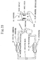
- Fig. 23 is a block diagram of refrigeration cycle equipment illustrating a pressure pulsation reduction method according to an eleventh embodiment which is not an embodiment according to the invention but helpful for the understanding thereof.
- high-temperature high-pressure gas refrigerant after compressed by a compressor 20 turns to liquid refrigerant when condensed in a condenser 21.
- the liquid refrigerant is reduced in pressure in regulator means 23, evaporated in an evaporator 24, and turns to low-temperature low-pressure gas refrigerant.
- the gas refrigerant is sucked in by the compressor 20.
- the compressor 20 contains an electric drive motor and is configured as follows. Motor rotation influences rotor rotation, along with which the clearance volume of a compression chamber varies. Fluid sucked in by the compression chamber is compressed and acquires specified pressure or specified rotation angle. The fluid is discharged at once thereafter from the compressor. Therefore, the pressure of the fluid discharged from the compressor 20 also contains a pulsation component including a higher harmonic wave component when the fundamental frequency is the rotational frequency of the compressor. Also, needless to mention that the pressure of the compressor on the suction side also contains the pulsation component including the higher harmonic wave component when the fundamental frequency is the rotational frequency of the compressor.
- pressure pulsation means needs to be installed in a flow channel near the compressor 20 so as to reduce pressure pulsation.
- a pressure difference between both ends of a perforated plate forms a contraction flow through the holes according to the pressure difference ( Fig. 24 ).
- shear effect in the surrounding fluid converts part of the energy of the contraction flow into vortex energy, thereby generating a vortex.
- a generated vortex is swept away from the holes by the contraction flow. Then, in the transfer process, it is converted into thermal energy, that is, temperature rise of the surrounding fluid, and pressure energy, that is, pulsation component release to the surrounding fluid when influenced by shearing and friction in the surrounding fluid.
- the vortex dissipates.
- a series of this vortex generation and dissipation are repeated continuously.
- the dimension of a vortex generated by the contraction flow at the holes depends upon a diameter d of the hole.
- a frequency f of pressure pulsation generated by a vortex is expressed as: f ⁇ U / d where U denotes the speed of the contraction flow, so that the generation period of a vortex is 1/f.
- pressure pulsation whose wavelength ⁇ is considerably longer than the diameter of the hole ( ⁇ >>d) enters near the contraction flow.
- pressure pulsation fluctuates periodically to the plus or minus side of the steady state pressure.
- the steady state pressure rises on the upstream side and drops on the downstream side of the holes at the instant of vortex generation as shown in Fig. 25 .
- the pressure pulsation reduction effect based on this principle is premised on that the pressure fluctuation cycle is considerably slower than the speed of vortex generation by the contraction flow. Then, the effect is especially high in the low frequency range.
- Fig. 27 shows experimental results that confirmed the effect of the pressure pulsation reduction method. More specifically, the figure shows a measured amount of pressure pulsation reduction in the case of no jet flow existing under the following condition: the perforated plate is installed in a flow channel through which pressure pulsation propagates; a jet flow is supplied to the flow channel through the holes of the perforated plate; and the frequency of the pressure pulsation and the speed of the jet flow are fluctuated.
- the horizontal axis shows the pressure pulsation frequency and the vertical axis shows the amount of pressure pulsation reduction.
- Fig. 27 (1) shows the experimental result of the case where the jet flow is blown out to a field where acoustic waves propagate.
- Fig. 27 shows experimental result of the case where the jet flow is blown out to a field where acoustic waves propagate.
- FIG. 27 (2) shows the experimental result of the case where the jet flow is blown out to a field where acoustic waves propagate.
- Fig. 27 (2) shows the experimental result of the case where the jet flow is sucked in. It should be noted that the speed of the jet flow shown in the figure has the following relation: Flow speed 1 ⁇ Flow speed 2 ⁇ Flow speed 3 ⁇ Flow speed 4.
- pressure pulsation reduction means 30 on the discharge side of the compressor 20 in the refrigeration cycle, pressure pulsation reduction means 30 to which the aforementioned mechanism is applied is installed.
- the pressure pulsation reduction means 30 contains a flow-channel separator 14, which is formed to narrow the flow channel.
- the flow-channel separator 14 is open on the upstream side and in contact with the surrounding wall on the downstream side. Then, the flow-channel separator 14 contains a large number of small holes 9 on the wall surrounding the flow channel narrowed.
- a fluid flowing into the pressure pulsation reduction means 30 passes through the flow channel narrowed of the flow-channel separator 14. This accelerates the flow speed of the fluid. From Bernoulli's theorem in fluid dynamics, the sum of static pressure and dynamic pressure of a fluid is equal at each point of flow. Dynamic pressure is proportional to squared fluid speed. Therefore, in the flow channel narrowed, dynamic pressure occurs depending on the fluid speed. Outside the flow channel narrowed, however, there is no flow and therefore no dynamic pressure occurs. Accordingly, static pressure outside the flow channel narrowed is higher than that in the flow channel narrowed. Consequently, static pressure at the both ends of the small holes 9 provided around the flow channel narrowed is higher outside than inside. This forms a flow through the small holes 9. Then, the fluid blown into the flow channel narrowed through the small holes 9 meets a fluid through the flow channel narrowed, and is then discharged from the pressure pulsation reduction means 30.
- the pressure pulsation reduction effect is obtained. Therefore, the pressure pulsation of the refrigerant flowing into the pressure pulsation reduction means 30 is reduced in pulsation in the section where the small holes 9 are provided. Reduction in the pressure pulsation of refrigerant allows preventing noise caused by pipeline vibrations.
- the pressure pulsation reduction means 30 may alternatively be installed on the suction side of the compressor 20. In this case, pressure pulsation reduction may be achieved on the suction side of the compressor. Otherwise, as shown in Fig. 29 , the pressure pulsation reduction means 30 may be installed on the suction side and the discharge side of the compressor instead. In this case, pressure pulsation reduction propagating to both the suction side and the discharge side of the compressor may be achieved. Still alternatively, as shown in Fig.
- the pressure pulsation reduction means 30 may be formed such that small holes 9 provided on pipeline walls on the discharge side and the suction side are connected by means of a connection pipe 31. This forms a flow from the small holes on the discharge side to the small holes on the suction side of the compressor, which allows reducing pressure pulsation on both the discharge side and the suction side.
- the pressure pulsation reduction effect can be achieved with any open area ratio of the small hole (that is defined as the total open area of the small hole for a given area of the duct wall).
- any open area ratio of the small hole that is defined as the total open area of the small hole for a given area of the duct wall.
- any size can be used for the diameter of the small hole.
- the most desirable size of the diameter of the small hole is as small as 1mm or 2mm. For practical purposes, however, a diameter up to 10mm is considered acceptable for the small hole.
- the flow-channel separator 14 is formed into a diffuser on the upstream side.
- a flow through the small holes 9 is the only requirement for noise reduction.
- a pipe whose diameter is the same as that of the section where the small holes 9 are provided is one possibility, for example.
- the configuration may include a plurality of perforated small ducts installed in the flow channel. This allows for higher pressure pulsation reduction.
- any refrigerant can be used for the refrigerant that flows inside the refrigeration cycle equipment, for example, such as single component refrigerants like R22 etc., mixed refrigerants of a three-component system like R407C, mixed refrigerants of a two-component system like R410A, HC refrigerants such as propane etc., and natural refrigerants such as CO2 etc.
- the pressure pulsation reducer 30 may be applied to pump equipment as shown in Fig. 31 through Fig. 34 .
- the pressure pulsation of a medium such as water or brine that flows through a flow channel can be reduced.
- the operation of this case will not be discussed here in detail, since it is the same as that of the refrigeration cycle equipment.
- Pressure pulsation reduction means may be installed on either the upstream side or the downstream side of a compressing section for compressing a fluid. From the structural point of view, therefore, a compressor 20 may contain the pressure pulsation reduction means.
- Fig. 35 is a diagram illustrating an internal structure of a single screw compressor according to a twelfth embodiment which is not an embodiment according to the invention but helpful for the understanding thereof.
- Pressure pulsation reduction means 30 is installed in an oil separator 43 on the downstream side of a compression chamber 42.
- a flow-channel separator 14 in the pres-sure pulsation reduction means 30 is in contact with the surrounding wall of the oil separator 43 on the upstream side.
- the flow-channel separator 14, on the downstream side, is formed into a nozzle so as to blow a fluid through a flow channel narrowed.
- small holes 9 are provided on the duct wall of the flow-channel separator 14 before the nozzle portion.
- the flow-channel separator 14 in the pressure pulsation reduction means 30 may alternatively be formed such that it is open on the upstream side, in contact with a cylindrical member that extends from the oil separator 43 and encloses the flow-channel separator 14, for example, on the downstream side, and includes small holes 9 in a large number.
- the air conditioning equipment includes a heat exchanger exchanging heat between refrigerant of a refrigeration cycle and air, a fan funning air to the heat exchanger, an air duct in which the fan is installed and through which an acoustic wave propagates, and a plurality of small holes blowing a jet to the air duct, and sucking a jet from the air duct according to a pressure difference between a blow side and a suction side of the fan. This allows for sufficient noise reduction in the low frequency region of a few hundred hertz or below.
Landscapes
- Engineering & Computer Science (AREA)
- Mechanical Engineering (AREA)
- General Engineering & Computer Science (AREA)
- Chemical & Material Sciences (AREA)
- Combustion & Propulsion (AREA)
- Structures Of Non-Positive Displacement Pumps (AREA)
- Other Air-Conditioning Systems (AREA)
- Duct Arrangements (AREA)
- Soundproofing, Sound Blocking, And Sound Damping (AREA)
- Air Filters, Heat-Exchange Apparatuses, And Housings Of Air-Conditioning Units (AREA)
Priority Applications (1)
| Application Number | Priority Date | Filing Date | Title |
|---|---|---|---|
| EP09013762.1A EP2154451B1 (en) | 2002-10-02 | 2003-08-26 | Pressure pulsation reducer of refrigeration cycle equipment |
Applications Claiming Priority (3)
| Application Number | Priority Date | Filing Date | Title |
|---|---|---|---|
| JP2002289663 | 2002-10-02 | ||
| JP2002289663 | 2002-10-02 | ||
| PCT/JP2003/010741 WO2004031660A1 (ja) | 2002-10-02 | 2003-08-26 | 空気調和装置及び送風装置及び機器の騒音低減方法及び冷凍サイクル装置の圧力脈動低減装置及びポンプ装置の圧力脈動低減装置及び機器の圧力脈動低減方法 |
Related Child Applications (1)
| Application Number | Title | Priority Date | Filing Date |
|---|---|---|---|
| EP09013762.1A Division-Into EP2154451B1 (en) | 2002-10-02 | 2003-08-26 | Pressure pulsation reducer of refrigeration cycle equipment |
Publications (3)
| Publication Number | Publication Date |
|---|---|
| EP1553360A1 EP1553360A1 (en) | 2005-07-13 |
| EP1553360A4 EP1553360A4 (en) | 2008-03-12 |
| EP1553360B1 true EP1553360B1 (en) | 2019-05-22 |
Family
ID=32063749
Family Applications (2)
| Application Number | Title | Priority Date | Filing Date |
|---|---|---|---|
| EP03799088.4A Expired - Lifetime EP1553360B1 (en) | 2002-10-02 | 2003-08-26 | Air conditioning equipment |
| EP09013762.1A Expired - Lifetime EP2154451B1 (en) | 2002-10-02 | 2003-08-26 | Pressure pulsation reducer of refrigeration cycle equipment |
Family Applications After (1)
| Application Number | Title | Priority Date | Filing Date |
|---|---|---|---|
| EP09013762.1A Expired - Lifetime EP2154451B1 (en) | 2002-10-02 | 2003-08-26 | Pressure pulsation reducer of refrigeration cycle equipment |
Country Status (6)
| Country | Link |
|---|---|
| US (1) | US7856837B2 (ja) |
| EP (2) | EP1553360B1 (ja) |
| JP (1) | JP4325867B2 (ja) |
| ES (2) | ES2732068T3 (ja) |
| HK (1) | HK1141074A1 (ja) |
| WO (1) | WO2004031660A1 (ja) |
Families Citing this family (23)
| Publication number | Priority date | Publication date | Assignee | Title |
|---|---|---|---|---|
| DE602005025418D1 (de) * | 2005-05-31 | 2011-01-27 | Carrier Corp | Verfahren und vorrichtung zur verringerung des von einem ölabscheider abgegebenen lärmpegels |
| JP4301227B2 (ja) * | 2005-09-15 | 2009-07-22 | セイコーエプソン株式会社 | 電気光学装置及びその製造方法、電子機器並びにコンデンサー |
| DE102005046728A1 (de) * | 2005-09-29 | 2007-04-12 | Airbus Deutschland Gmbh | Geräuscharme Durchflussdrosselung fluidführender Rohre |
| DE102006050339A1 (de) * | 2006-10-25 | 2008-04-30 | Valeo Klimasysteme Gmbh | Belüftungsanlage mit Schallbarriere |
| JP4610626B2 (ja) * | 2008-02-20 | 2011-01-12 | 三菱電機株式会社 | 天井埋め込み型空気調和機に配置される熱交換器及び天井埋め込み型空気調和機 |
| US11828678B2 (en) * | 2010-03-15 | 2023-11-28 | Klatu Networks, Inc. | Managing the effectiveness of repairs in refrigeration assets |
| US10456686B2 (en) | 2012-09-05 | 2019-10-29 | Zynga Inc. | Methods and systems for adaptive tuning of game events |
| US10087954B2 (en) | 2013-02-08 | 2018-10-02 | Trane International Inc. | HVAC system with noise reducing tube |
| JP6139189B2 (ja) * | 2013-03-13 | 2017-05-31 | 東プレ株式会社 | 送風ユニット |
| US9835176B2 (en) | 2013-04-05 | 2017-12-05 | Acoustiflo Llc | Fan inlet air handling apparatus and methods |
| US10561944B2 (en) | 2014-09-10 | 2020-02-18 | Zynga Inc. | Adjusting object adaptive modification or game level difficulty and physical gestures through level definition files |
| US9675889B2 (en) | 2014-09-10 | 2017-06-13 | Zynga Inc. | Systems and methods for determining game level attributes based on player skill level prior to game play in the level |
| EP3211331A1 (en) * | 2016-02-25 | 2017-08-30 | Halton OY | Apparatus for conditioning a space |
| CN107166538A (zh) * | 2017-06-22 | 2017-09-15 | 珠海格力电器股份有限公司 | 空调器 |
| DE202017006578U1 (de) * | 2017-12-22 | 2019-03-25 | Thomas Roggenkamp | Klimaschrank |
| CN110906594A (zh) | 2018-09-14 | 2020-03-24 | 开利公司 | 油分离器以及具有该油分离器的空调系统 |
| CN111256281B (zh) * | 2018-11-30 | 2021-10-22 | 广东美的制冷设备有限公司 | 运行控制方法及系统、压缩机和空调器 |
| TWI710706B (zh) * | 2019-05-24 | 2020-11-21 | 宏碁股份有限公司 | 離心式散熱風扇 |
| DE102020207407A1 (de) * | 2020-06-16 | 2021-12-16 | BSH Hausgeräte GmbH | Kältegerät und Verdichter dafür |
| TWI790737B (zh) * | 2021-09-06 | 2023-01-21 | 宏碁股份有限公司 | 具散熱和前饋式主動噪音控制功能之電子系統 |
| CN114001420B (zh) * | 2021-10-27 | 2023-07-04 | 上海民航新时代机场设计研究院有限公司 | 一种低噪音全热净效新风机 |
| CN114608789B (zh) * | 2022-04-07 | 2023-03-21 | 中国空气动力研究与发展中心低速空气动力研究所 | 一种研究喷流噪声及声传播的试验方法 |
| JP2024052573A (ja) * | 2022-09-30 | 2024-04-11 | ダイキン工業株式会社 | 空調装置及び空気清浄機 |
Family Cites Families (24)
| Publication number | Priority date | Publication date | Assignee | Title |
|---|---|---|---|---|
| US2875787A (en) * | 1956-03-27 | 1959-03-03 | Westinghouse Air Brake Co | Pulsation dampener device |
| US3070977A (en) * | 1961-03-31 | 1963-01-01 | Heat X Inc | Refrigeration system, including oil separator and muffler unit and oil return arrangement |
| JPS5722492A (en) * | 1980-07-17 | 1982-02-05 | Nippon Denso Co | Silencer |
| JPS57173686A (en) * | 1981-04-20 | 1982-10-26 | Hitachi Plant Eng & Constr Co | Muffler for blowing duct |
| ATE25898T1 (de) | 1982-03-18 | 1987-03-15 | British Telecomm | Piezoelektrische und pyroelektrische folie. |
| JPS58195908A (ja) | 1982-05-11 | 1983-11-15 | Shinkichi Doi | 道路の速度規制に対する自動車速度の順応方法 |
| JPS58194908U (ja) * | 1982-06-21 | 1983-12-24 | マツダ株式会社 | 自動車の空調装置 |
| JPS5921951A (ja) | 1982-07-23 | 1984-02-04 | 三洋電機株式会社 | ヒ−トポンプ式分離型空気調和機 |
| JPS5927164U (ja) * | 1982-08-12 | 1984-02-20 | 株式会社ボッシュオートモーティブ システム | 複動式圧縮機 |
| JPS613943A (ja) * | 1984-06-18 | 1986-01-09 | Toupure Kk | 空気調和設備 |
| JP3240628B2 (ja) * | 1991-06-17 | 2001-12-17 | 株式会社日立製作所 | 空気調和機 |
| JP3332057B2 (ja) | 1994-03-11 | 2002-10-07 | 石川島播磨重工業株式会社 | 超音速航空機用排気ノズルのライナ構造 |
| JP2741840B2 (ja) | 1994-06-24 | 1998-04-22 | 株式会社ゴーセン | 釣糸の巻き換え用具及びこれを取り付けた釣糸の巻き糸体 |
| JP3400108B2 (ja) | 1994-06-27 | 2003-04-28 | アイシン精機株式会社 | 配管装置及び配管装置を備えた空調機 |
| US5638940A (en) * | 1994-07-23 | 1997-06-17 | Aoyama; Yoshitaka | Parts send-out control device for vibratory parts feeder |
| JP2864099B2 (ja) | 1994-11-26 | 1999-03-03 | 好高 青山 | 部品供給管路の消音装置 |
| JPH09112488A (ja) * | 1995-10-17 | 1997-05-02 | Mitsubishi Heavy Ind Ltd | 遠心フアン |
| CA2164370A1 (en) * | 1995-12-04 | 1997-06-05 | Donald L. Allen | Reactive acoustic silencer |
| CN1143087C (zh) * | 1997-06-17 | 2004-03-24 | 大金工业株式会社 | 空调机 |
| JPH11107959A (ja) * | 1997-09-30 | 1999-04-20 | Sanyo Electric Co Ltd | 密閉型圧縮機の吐出管 |
| JP2000292077A (ja) | 1999-02-03 | 2000-10-20 | Nippon Soken Inc | 熱交換器 |
| JP2002250535A (ja) | 2001-02-23 | 2002-09-06 | Mitsubishi Heavy Ind Ltd | 空調用室内ユニットおよびその空調用室内ユニットを備えた空気調和機 |
| JP2002350003A (ja) | 2001-05-22 | 2002-12-04 | Hitachi Ltd | 空気調和機 |
| JP3809520B2 (ja) | 2001-07-04 | 2006-08-16 | 独立行政法人 宇宙航空研究開発機構 | 微細噴流制御式吸音システム |
-
2003
- 2003-08-26 EP EP03799088.4A patent/EP1553360B1/en not_active Expired - Lifetime
- 2003-08-26 EP EP09013762.1A patent/EP2154451B1/en not_active Expired - Lifetime
- 2003-08-26 JP JP2004541215A patent/JP4325867B2/ja not_active Expired - Lifetime
- 2003-08-26 WO PCT/JP2003/010741 patent/WO2004031660A1/ja active Application Filing
- 2003-08-26 ES ES03799088T patent/ES2732068T3/es not_active Expired - Lifetime
- 2003-08-26 ES ES09013762.1T patent/ES2443492T3/es not_active Expired - Lifetime
- 2003-08-26 US US10/529,870 patent/US7856837B2/en active Active
-
2010
- 2010-08-02 HK HK10107351.6A patent/HK1141074A1/xx not_active IP Right Cessation
Non-Patent Citations (1)
| Title |
|---|
| None * |
Also Published As
| Publication number | Publication date |
|---|---|
| US20070060038A1 (en) | 2007-03-15 |
| ES2732068T3 (es) | 2019-11-20 |
| EP2154451A1 (en) | 2010-02-17 |
| WO2004031660A1 (ja) | 2004-04-15 |
| JP4325867B2 (ja) | 2009-09-02 |
| HK1141074A1 (en) | 2010-10-29 |
| JPWO2004031660A1 (ja) | 2006-02-02 |
| EP1553360A1 (en) | 2005-07-13 |
| US7856837B2 (en) | 2010-12-28 |
| EP1553360A4 (en) | 2008-03-12 |
| EP2154451B1 (en) | 2013-11-06 |
| ES2443492T3 (es) | 2014-02-19 |
Similar Documents
| Publication | Publication Date | Title |
|---|---|---|
| EP1553360B1 (en) | Air conditioning equipment | |
| EP2618066B1 (en) | Blower for outdoor unit, outdoor unit, and refrigeration cycle device | |
| WO2005095875A1 (ja) | 流路装置、冷凍サイクル装置、圧力脈動低減装置、圧力脈動低減方法 | |
| KR20070099053A (ko) | 압축기 배출 소음기 | |
| US11073145B2 (en) | Pressure pulsation traps | |
| JPH07120104A (ja) | 空気調和機 | |
| CN109247023B (zh) | 离心送风机、空气调节装置以及制冷循环装置 | |
| JP4659066B2 (ja) | 流路装置 | |
| KR100358237B1 (ko) | 흠음장치 | |
| CN111247379B (zh) | 制冷循环装置用单元、制冷循环装置及电气设备 | |
| JP5521648B2 (ja) | 消音ボックス付送風機 | |
| JP7301236B2 (ja) | 遠心送風機のスクロールケーシング、このスクロールケーシングを備えた遠心送風機、空気調和装置及び冷凍サイクル装置 | |
| JP2003074499A (ja) | 送風機及びこれを使用した空気調和機 | |
| JP7038839B2 (ja) | 室外機及び冷凍サイクル装置 | |
| JP4925698B2 (ja) | 空気調和装置 | |
| CN110573808B (zh) | 制冷循环装置和具有该制冷循环装置的电气设备 | |
| JP2022126944A (ja) | ターボ送風機 | |
| CN117433179A (zh) | 一种热泵设备及其室外机 | |
| KR20010008001A (ko) | 원심형 냉매 압축기의 소음 소산 장치 |
Legal Events
| Date | Code | Title | Description |
|---|---|---|---|
| PUAI | Public reference made under article 153(3) epc to a published international application that has entered the european phase |
Free format text: ORIGINAL CODE: 0009012 |
|
| 17P | Request for examination filed |
Effective date: 20050415 |
|
| AK | Designated contracting states |
Kind code of ref document: A1 Designated state(s): AT BE BG CH CY CZ DE DK EE ES FI FR GB GR HU IE IT LI LU MC NL PT RO SE SI SK TR |
|
| RBV | Designated contracting states (corrected) |
Designated state(s): DE ES GB IT |
|
| RAP1 | Party data changed (applicant data changed or rights of an application transferred) |
Owner name: JAPAN AEROSPACE EXPLORATION AGENCY Owner name: MITSUBISHI DENKI KABUSHIKI KAISHA |
|
| A4 | Supplementary search report drawn up and despatched |
Effective date: 20080212 |
|
| 17Q | First examination report despatched |
Effective date: 20090421 |
|
| RAP1 | Party data changed (applicant data changed or rights of an application transferred) |
Owner name: MITSUBISHI ELECTRIC CORPORATION Owner name: MITSUBISHI DENKI KABUSHIKI KAISHA |
|
| RAP1 | Party data changed (applicant data changed or rights of an application transferred) |
Owner name: MITSUBISHI ELECTRIC CORPORATION |
|
| REG | Reference to a national code |
Ref country code: DE Ref legal event code: R079 Ref document number: 60352044 Country of ref document: DE Free format text: PREVIOUS MAIN CLASS: F24F0013060000 Ipc: F24F0013240000 |
|
| GRAP | Despatch of communication of intention to grant a patent |
Free format text: ORIGINAL CODE: EPIDOSNIGR1 |
|
| RIC1 | Information provided on ipc code assigned before grant |
Ipc: F04D 29/66 20060101ALI20181113BHEP Ipc: F24F 13/24 20060101AFI20181113BHEP Ipc: F24F 1/00 20110101ALI20181113BHEP Ipc: F25B 41/00 20060101ALI20181113BHEP |
|
| INTG | Intention to grant announced |
Effective date: 20181214 |
|
| RIN1 | Information on inventor provided before grant (corrected) |
Inventor name: UCHIDA, TSUYOSHI Inventor name: YAMASHITA, KOUJI Inventor name: NAGAI, KENICHIRO Inventor name: TAKEDA, KATSUMI Inventor name: OINUMA, HIDESHI Inventor name: ISHII, TATSUYA |
|
| RIC1 | Information provided on ipc code assigned before grant |
Ipc: F25B 41/00 20060101ALI20181113BHEP Ipc: F24F 13/24 20060101AFI20181113BHEP Ipc: F04D 29/66 20060101ALI20181113BHEP Ipc: F24F 1/00 20190101ALI20181113BHEP |
|
| GRAS | Grant fee paid |
Free format text: ORIGINAL CODE: EPIDOSNIGR3 |
|
| GRAA | (expected) grant |
Free format text: ORIGINAL CODE: 0009210 |
|
| AK | Designated contracting states |
Kind code of ref document: B1 Designated state(s): DE ES GB IT |
|
| REG | Reference to a national code |
Ref country code: GB Ref legal event code: FG4D |
|
| REG | Reference to a national code |
Ref country code: DE Ref legal event code: R096 Ref document number: 60352044 Country of ref document: DE |
|
| REG | Reference to a national code |
Ref country code: ES Ref legal event code: FG2A Ref document number: 2732068 Country of ref document: ES Kind code of ref document: T3 Effective date: 20191120 |
|
| REG | Reference to a national code |
Ref country code: DE Ref legal event code: R097 Ref document number: 60352044 Country of ref document: DE |
|
| PLBE | No opposition filed within time limit |
Free format text: ORIGINAL CODE: 0009261 |
|
| STAA | Information on the status of an ep patent application or granted ep patent |
Free format text: STATUS: NO OPPOSITION FILED WITHIN TIME LIMIT |
|
| 26N | No opposition filed |
Effective date: 20200225 |
|
| PGFP | Annual fee paid to national office [announced via postgrant information from national office to epo] |
Ref country code: IT Payment date: 20220712 Year of fee payment: 20 Ref country code: GB Payment date: 20220707 Year of fee payment: 20 Ref country code: ES Payment date: 20220901 Year of fee payment: 20 Ref country code: DE Payment date: 20220621 Year of fee payment: 20 |
|
| P01 | Opt-out of the competence of the unified patent court (upc) registered |
Effective date: 20230512 |
|
| REG | Reference to a national code |
Ref country code: DE Ref legal event code: R071 Ref document number: 60352044 Country of ref document: DE |
|
| REG | Reference to a national code |
Ref country code: ES Ref legal event code: FD2A Effective date: 20230901 |
|
| REG | Reference to a national code |
Ref country code: GB Ref legal event code: PE20 Expiry date: 20230825 |
|
| PG25 | Lapsed in a contracting state [announced via postgrant information from national office to epo] |
Ref country code: GB Free format text: LAPSE BECAUSE OF EXPIRATION OF PROTECTION Effective date: 20230825 Ref country code: ES Free format text: LAPSE BECAUSE OF EXPIRATION OF PROTECTION Effective date: 20230827 |