EP1524562A2 - Appareil d'alimentation de feuilles et système de formation d'image - Google Patents
Appareil d'alimentation de feuilles et système de formation d'image Download PDFInfo
- Publication number
- EP1524562A2 EP1524562A2 EP04024547A EP04024547A EP1524562A2 EP 1524562 A2 EP1524562 A2 EP 1524562A2 EP 04024547 A EP04024547 A EP 04024547A EP 04024547 A EP04024547 A EP 04024547A EP 1524562 A2 EP1524562 A2 EP 1524562A2
- Authority
- EP
- European Patent Office
- Prior art keywords
- sheet
- deck
- sheets
- decks
- conveying path
- Prior art date
- Legal status (The legal status is an assumption and is not a legal conclusion. Google has not performed a legal analysis and makes no representation as to the accuracy of the status listed.)
- Granted
Links
- 238000005304 joining Methods 0.000 claims abstract description 55
- 238000011144 upstream manufacturing Methods 0.000 claims abstract description 36
- 230000000694 effects Effects 0.000 claims description 18
- 238000012840 feeding operation Methods 0.000 claims description 9
- 238000001514 detection method Methods 0.000 claims description 4
- 230000003247 decreasing effect Effects 0.000 claims 2
- 238000012545 processing Methods 0.000 description 39
- 238000000034 method Methods 0.000 description 21
- 238000007599 discharging Methods 0.000 description 16
- 238000010586 diagram Methods 0.000 description 9
- 238000010276 construction Methods 0.000 description 8
- 230000002093 peripheral effect Effects 0.000 description 7
- 238000004891 communication Methods 0.000 description 6
- 238000013461 design Methods 0.000 description 6
- 230000006870 function Effects 0.000 description 6
- 238000006243 chemical reaction Methods 0.000 description 4
- 238000012937 correction Methods 0.000 description 4
- 230000006835 compression Effects 0.000 description 3
- 238000007906 compression Methods 0.000 description 3
- 239000000463 material Substances 0.000 description 3
- 238000012546 transfer Methods 0.000 description 3
- 230000004075 alteration Effects 0.000 description 2
- 238000003705 background correction Methods 0.000 description 2
- 230000005540 biological transmission Effects 0.000 description 2
- 238000004140 cleaning Methods 0.000 description 2
- 239000000470 constituent Substances 0.000 description 2
- 230000003111 delayed effect Effects 0.000 description 2
- 238000009826 distribution Methods 0.000 description 2
- 238000009499 grossing Methods 0.000 description 2
- 238000004519 manufacturing process Methods 0.000 description 2
- 230000000873 masking effect Effects 0.000 description 2
- 238000004080 punching Methods 0.000 description 2
- 238000000926 separation method Methods 0.000 description 2
- 238000004904 shortening Methods 0.000 description 2
- 238000009825 accumulation Methods 0.000 description 1
- 230000000052 comparative effect Effects 0.000 description 1
- 230000010485 coping Effects 0.000 description 1
- 238000005520 cutting process Methods 0.000 description 1
- 230000000994 depressogenic effect Effects 0.000 description 1
- 239000011521 glass Substances 0.000 description 1
- 230000007774 longterm Effects 0.000 description 1
- 239000011159 matrix material Substances 0.000 description 1
- 230000002441 reversible effect Effects 0.000 description 1
- 238000005070 sampling Methods 0.000 description 1
- 230000001360 synchronised effect Effects 0.000 description 1
Images


Classifications
-
- G—PHYSICS
- G03—PHOTOGRAPHY; CINEMATOGRAPHY; ANALOGOUS TECHNIQUES USING WAVES OTHER THAN OPTICAL WAVES; ELECTROGRAPHY; HOLOGRAPHY
- G03G—ELECTROGRAPHY; ELECTROPHOTOGRAPHY; MAGNETOGRAPHY
- G03G15/00—Apparatus for electrographic processes using a charge pattern
- G03G15/65—Apparatus which relate to the handling of copy material
- G03G15/6502—Supplying of sheet copy material; Cassettes therefor
- G03G15/6508—Automatic supply devices interacting with the rest of the apparatus, e.g. selection of a specific cassette
-
- B—PERFORMING OPERATIONS; TRANSPORTING
- B65—CONVEYING; PACKING; STORING; HANDLING THIN OR FILAMENTARY MATERIAL
- B65H—HANDLING THIN OR FILAMENTARY MATERIAL, e.g. SHEETS, WEBS, CABLES
- B65H2402/00—Constructional details of the handling apparatus
- B65H2402/10—Modular constructions, e.g. using preformed elements or profiles
-
- G—PHYSICS
- G03—PHOTOGRAPHY; CINEMATOGRAPHY; ANALOGOUS TECHNIQUES USING WAVES OTHER THAN OPTICAL WAVES; ELECTROGRAPHY; HOLOGRAPHY
- G03G—ELECTROGRAPHY; ELECTROPHOTOGRAPHY; MAGNETOGRAPHY
- G03G2215/00—Apparatus for electrophotographic processes
- G03G2215/00362—Apparatus for electrophotographic processes relating to the copy medium handling
- G03G2215/00443—Copy medium
- G03G2215/00447—Plural types handled
Definitions
- the invention relates to a sheet supplying apparatus provided with a plurality of sheet decks stacking various sheets thereon and capable of supplying many kinds of sheets, and an image forming system provided with the sheet supplying apparatus and for forming images on the many kinds of sheets supplied from the sheet supplying apparatus, and providing the sheets in the form of bundle to a user.
- Fields related to digital copying machines and printing include a field called on-demand print, and in recent years, this field has been attracting attention.
- the on-demand print can meet many kinds and small lots of demands on demand from customers, and facilitates the alteration of contents, and is suited for the production of documents such as manuals and pamphlets for individuals.
- the on-demand print facilitates the alteration of contents and can therefore greatly curtail the stock of printed documents or the like.
- the on-demand print can accomplish the great shortening of the number of steps and time by data inputting to the completion of bookbinding being effected by in-line, the great shortening of the time limit of delivery and the curtailment of delivery cost based on the ease of data forwarding by customers and a digital circuit being connected together.
- An image forming apparatus such as a digital copying machine which has realized such an on-demand print technique is improved in its quality of image to a level approximate to printed matter by the recent heightening of the quality of image, and has come to be used for the printing of pamphlets such as catalogs and manuals of products, or pamphlets such as distributed matter in offices or the like.
- Image forming systems using an image forming apparatus such as a copying machine coping with the on-demand print include what has been proposed as a large-sized image forming system for executing, by a series of job operations, such post-treating processes as the Z fold process of receiving the supply of sheets from a sheet supplying apparatus of large capacity, and folding a sheet fed out from the image forming apparatus into a substantially Z-shape (for example, the folding process of folding A3 size into A4 size, and thereafter folding one portion of A4 size into a half), the inserter process of inserting a different kind of sheet between the sheets, the stapling process of stapling a bundle of sheets, the punching process of punching the bundle of sheets, and the bookbinding process, in order to cope with a variety of sheets.
- the sheet supplying apparatus as is disclosed in Japanese Patent Application Laid-Open No. 2001-506212, is formed by a plurality of sheet decks stacking different kinds of sheets thereon being connected in series (in tandem).
- a variety of sheets include sheets differing in size, thickness, material, etc.
- the image forming system in which the sheet decks of the sheet supplying apparatus of large capacity are connected in series (in tandem) shares a sheet conveying path from each sheet deck to the image forming apparatus, and therefore has suffered from the following problems.
- the sheet deck for supplying the sheets is changed from a sheet deck nearest to the image forming apparatus to a sheet deck farthest from the image forming apparatus.
- the farthest sheet deck which has a long sheet conveying path, supplies a sheet at an interval corresponding to the long conveying distance, with respect to a sheet supplied from the nearest sheet deck.
- the system printer according to the second example of the conventional art suffers from the problem that only one sheet deck can be connected thereto and the kinds of the sheets are limited.
- the sheet supplying apparatus of the present invention is a sheet supplying apparatus having a plurality of sheet decks for supplying sheets, each of the sheet decks has sheet stacking means for supporting the sheets thereon a sheet conveying path for guiding the sheets from an upstream side to a downstream side and a joining conveying path joining the sheet conveying path for guiding the sheets from the sheet stacking means to the sheet conveying path, wherein the sheet decks are connected in such a manner that the respective sheet conveying paths are connected thereto, and controlling means for controlling the feeding of the sheets by each sheet deck, wherein the controlling means judges the position of the sheet deck for supplying a preceding sheet prior to by one a sheet supplied in predetermined order when the sheets are supplied in order from each sheet deck, and controls so as to pre-feed the sheet to the vicinity of the upstream side of a joining point of the sheet conveying path in the sheet deck of the preceding sheet and the joining conveying path when the judged sheet deck is disposed downstream of the sheet deck for supplying the sheet in
- the sheet supplying apparatus of the present invention is a sheet supplying apparatus having a plurality of sheet decks for supplying sheets, each of the sheet decks has sheet stacking means for supporting the sheets thereon a sheet conveying path for guiding the sheets from an upstream side to a downstream side sheet conveying means for conveying the sheets along the sheet conveying path sheet supplying means for feeding out the sheets from the sheet stacking means a joining conveying path joining the sheet conveying path for guiding the sheets from the sheet stacking means to the sheet conveying path, wherein the sheet deck are connected in such a manner that the respective sheet conveying paths are connected thereto; sheet detecting means for detecting the sheets conveyed thereto on the sheet conveying path; and controlling means for controlling the feeding of the sheets by each sheet deck, the controlling means judges the position of the sheet deck for supplying a preceding sheet prior to by one a sheet supplied in predetermined order when the sheets are supplied in order from each sheet deck, and operatively controls the sheet conveying means of each sheet deck when the judge
- the image forming system of the present invention is an image forming system provided with an image forming apparatus for forming an image on a sheet, a sheet supplying apparatus having a plurality of sheet decks, each of the sheet decks has sheet stacking means for supporting the sheets thereon a sheet conveying path for guiding the sheets from an upstream side to a downstream side a joining conveying path joining the sheet conveying path for guiding the sheets from the sheet stacking means to the sheet conveying path, wherein the sheet decks are connected in such a manner that the respective sheet conveying paths are connected thereto; and controlling means for controlling the feeding of the sheets of each sheet deck, the sheet supplying apparatus being connected to the image forming apparatus to thereby supply the sheets from the sheet decks to the image forming apparatus, the controlling means judges the position of the sheet deck for supplying a preceding sheet prior to by one the sheet supplied in predetermined order when the sheets are supplied in order from each sheet deck, and controls so as to pre-feed the sheet to the vicinity of the upstream side of
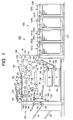
- Fig. 1 is a cross-sectional view showing the construction of the image forming system according to the embodiment of the present invention.
- the image forming system 1000 is comprised of an image forming apparatus 1001 which is an apparatus to be supplied with sheets and a sheet supplying apparatus 1002 connected thereto.
- the sheet supplying apparatus 1002 is comprised of four sheet decks 1200a, 1200b, 1200c and 1200d connected in series.
- the number of the sheet decks is not restricted to four, but a plurality of sheet decks can be connected. Also, when the sheet decks are to be described without the four sheet decks being specified, the reference numeral 1200 is used.
- the image forming apparatus 1001 and the sheet supplying apparatus 1002 will hereinafter be described in the named order.
- the image forming apparatus 1001 is comprised of a main body 100, an automatic document feeder 180 provided in the upper portion of the main body 100, and a discharged sheet treating apparatus 190 provided by the side of the main body 100.
- the main body 100 of the image forming apparatus 1001 is provided with an original plate (platen glass plate) 101 as a document supporting stand in the upper portion thereof.
- a scanner 102 is comprised of an original illuminating lamp 103, a scanning mirror 104, etc.
- the image of a document placed on the original plate 101 is scanned by the scanner 102 controlled so as to be reciprocally moved in a predetermined direction (a horizontal direction in Fig. 1) by a motor, not shown, and reflected light from the document is transmitted through a lens 108 through the intermediary of the scanning mirrors 104, 105 and 106 and is imaged on an image sensor portion (CCD sensor) 109, whereby it is converted into an electrical signal.
- CCD sensor image sensor portion
- An exposure controlling portion 120 is comprised of a laser output portion, a polygon scanner, etc., not shown, and applies a laser beam 129 to the photosensitive drum 110 of an image forming portion 126.
- the laser beam 129 is modulated on the basis of an image signal resulting from predetermined image processing which will be described later having been effected on an electrical signal obtained by photoelectrically converting the reflected light from the document outputted from the image sensor portion 109.
- a primary charging device 112 a developing device 121, a transfer charging device 118, a separation charging device 119, a cleaning apparatus 116 and a pre-exposure lamp 114 which, together with the photosensitive drum 110, constitute the image forming portion 126.
- the photosensitive drum 110 is adapted to be rotated in the direction of arrow by a motor, not shown, and is charged to desired potential by the primary charging device 112, whereafter the laser beam 129 from the exposure controlling portion 120 is applied to the photosensitive drum 110, whereby an electrostatic latent image is formed on the outer peripheral surface thereof.
- the electrostatic latent image formed on the photosensitive drum 110 is developed by the developing device 121 and is visualized as a toner image.
- a sheet P supplied from an upper cassette 131 or a lower cassette 132 by a pickup roller 133 or 134 is fed into the main body 100 of the image forming apparatus 1001 by sheet supplying rollers 135 or 136, and passes through a sheet path 160, and thereafter is fed into between the photosensitive drum 110 and the transfer charging device 118 by registration rollers 137.
- a sheet fed from the sheet supplying apparatus 1002 to the registration on the photosensitive drum 110 is transferred to these sheets P when they pass the outer periphery of the photosensitive drum 110.
- the photosensitive drum 120 after the toner image has been transferred to the sheet P has any residual toner thereon removed by the cleaning apparatus 116, and any residual charges are eliminated by the pre-exposure lamp 114.
- the sheet after the transfer is separated from the image forming portion 126 by the separation charging device 119, and is conveyed away from the photosensitive drum 110 by a conveying belt 130.
- the toner image on the sheet is fixed on the sheet by the sheet being re-charged by ante-fixing charging devices 139, 140, and pressurized and heated in a fixing device 141.
- the sheet having had the toner image fixed thereon is discharged out of the main body 100 of the image forming apparatus 1001 by discharge rollers 142.
- a sheet discharging flapper 154 is adapted to change over a sheet path on a sheet discharge side and a sheet path on a two-side recording side or a multiplex recording side.
- the sheet fed out from the discharge rollers 142 is conveyed to the sheet path on the two-side recording side or the multiplex recording side when the sheet discharging flapper 154 is above.
- the sheet having had the toner image on a first side thereof fixed is fed out from the discharge rollers 142 and reversed through a reversing path 155, and is directed through a lower conveying path 158 to a sheet re-supplying tray 156.
- a multiplex flapper 157 is adapted to change over the sheet path on the two-side recording side and the sheet path on the multiplex recording side, and when leftwardly brought down, can guide the sheet directly to the lower conveying path 158 without the intermediary of the reversing path 155 to thereby effect multiplex recording on the sheet.
- a sheet supplying 159 is adapted to supply the sheet to the image forming portion 126 side through a sheet path 160.
- Discharge rollers 161 are disposed near the sheet discharging flapper 154, and are adapted to discharge the sheet fed from the discharge rollers 142 out of the apparatus in a state in which the sheet discharging flapper 154 is changed over to a discharging side (is not above).
- the sheet discharging flapper 154 is upwardly inclined so that sheets having had the toner image thereon fixed may pass through the lower conveying path 158 and be stored in the sheet re-supplying tray 156.
- the sheets stored in the sheet re-supplying tray 156 are separated one by one from below by separating and conveying rollers 165 and are again directed to the registration rollers 137 through the sheet path 160.
- the sheet discharging flapper 154 When the sheet is to be discharged from the main body 100 with its front side and back side reversed, the sheet discharging flapper 154 is raised upwardly and the multiplex flapper 157 is rightwardly brought down. Thereupon, the sheet to be discharged is once fed to the reversing path 155 side and is conveyed to a second feeding roller 162a side by the reverse rotation of reversing rollers 163 at the timing where at the trailing edge of the sheet has passed first feeding rollers 162, and is discharged out of the apparatus by discharge rollers 161.
- the automatic document feeder (DF) 180 is provided in the upper portion of the main body 100 and is adapted to automatically feed a document into the main body 100.
- the automatic document feeder (DF) 180 separates a bundle of documents placed on a document placing stand 181 by a user one by one from the uppermost document by a sheet supplying roller 182, and conveys them onto the original plate 101 by a document sheet supplying roller 164. Thereafter, the document is scanned by the scanner 102. The thus scanned document is discharged onto a document discharging stand 183, or is returned to the document placing stand 181.
- a discharged sheet treating apparatus 190 is installed by the side of the main body 100, and is adapted to put in order and bind the sheets fed out from the main body 100.
- the discharged sheet post-treating operation such as sorting and stapling are not set
- the sheets pass through a conveying path 194 and are discharged onto a sheet discharging tray 191.
- the discharged sheet post-treating operation is set, the sheets pass through a conveying path 195 and are discharged one by one onto and stacked on a treating tray 193 and are put in order.
- the sheets in the image forming for the first copy are made into a bundle shape and bound (stapled), and are selectively discharged onto the sheet discharging tray 191 or a sheet discharging tray 192.
- the discharged sheet post treating operation basically the sheets are bundle-discharged onto the sheet discharging tray 192, but when the sheet discharging tray 192 is full of the sheets, the destination of discharge is changed over to the sheet discharging tray 191.
- the sheet discharging trays 191 and 192 have their upward and downward movement controlled by a motor, not shown, and before the start of the image forming operation, the sheet discharging tray 191 (or 192) which has become capable of stacking the sheets thereon is adapted to be moved up or down so as to come to the position of the treating tray 193.
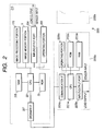
- Fig. 2 is a block diagram showing the construction of the controlling portion 210 of the image forming apparatus 1001 and controlling portions 2200a to 2200d provided in respective sheet decks 1200. the description of the controlling portions of the sheet decks 1200a to 1200d and the description of the construction thereof will be made later.
- a CPU 201 for effecting basic control has connected thereto, by an address bus and a data bus, a ROM 206 having a control program written thereinto, a work RAM 205 for effecting processing, and an input output port 204.
- a part of the area of the RAM 205 is a backup RAM from which data is not erased even if a power supply is cut off.
- the input/output port 204 has connected thereto various load devices such as a motor and a clutch controlled by the CPU 201, and an input device to the CPU 201, such as a sensor for detecting the position of the sheet.
- the CPU 201 is adapted to successively effect the control of an input and an output through the input output port 204 in accordance with the contents of the control program of the ROM 206 to thereby execute the image forming process.
- an operating portion 203 is connected to the CPU 201.
- the CPU 201 is adapted to control the display means and key input means of the operating portion 203.
- the CPU 201 is adapted to effect the display of the operating state of the image forming apparatus 1001 and the operating mode set by a key input, to the display means of the operating portion 203 (the details of this will be described later in connection with Fig. 6).
- the CPU 201 has connected thereto an image processing portion 110 for processing a signal converted into an electrical signal by the image sensor portion 109 (see Fig. 1), and an image memory portion 3 for accumulating a processed image therein.
- Fig. 3 is a block diagram showing the internal construction of the image processing portion 170.
- Fig. 4 is a block diagram showing the relation between the image memory portion 3 and the image processing portion 170, etc.
- the image of the document formed on the image sensor portion (CCD sensor) 109 through the lens 108 is converted into an analogue electrical signal by the image sensor portion 109 (See Fig. 3).
- the converted image information is inputted to an analogue signal processing portion 300 and is subjected to sampling, holding, the correction of a dark level, etc., whereafter it is analogue-digital-converted (A/D-converted) by an A/D SH processing portion 301, and shading correction is further effected on the digitized signal.
- the shading correction there are effected correction for the unevenness of each pixel the image sensor portion 109 has, and correction for the unevenness of the quantity of light due to the position based on the light distribution characteristic of the document illuminating lamp 103.
- RGB interline correction in an RGB interline correcting portion 302.
- the light is subjected to a input masking process in an input masking portion 303 and an RGB value remaining outputted from the image sensor portion 109 in which conversion from luminance data to density data is effected is subject to the influence of a color filter mounted on the image sensor portion 109 and therefore has the influence corrected and is converted into a genuine RGB value.
- the image is zooming-processed at a desired zooming rate in a zooming portion 304.
- the zoomed image data is sent to the image memory portion 3 and the image is accumulated therein.
- the image data of a computer is also inputted from an external I/F processing portion 4 to the image memory portion 3.
- the image data is sent from the image memory portion 3 to a ⁇ correcting portion 305.
- the ⁇ correcting portion 305 in order to provide an output conforming to a density value set by the operating portion 203 (see Fig. 2), the conversion of density data corresponding to desired output density is effected from the original density data on the basis of a look-up table (LUT) taking the characteristic of the printer into account.
- LUT look-up table
- the density data is sent to a binarizing portion 306.
- the binarizing portion 306 the binarization of the multi-value density data is effected.
- the density value assumes any value between "0" to "255,” but by being binarized, the density value becomes only two, e.g., "0" or "255.” That is, in order to represent the density of a certain pixel, data of 8 bits has been necessary, whereas by being binarized, a data amount of 1 bit becomes enough. Thereby, a memory capacity for storing the image data is reduced.
- an error diffusing method is used as a technique of effecting halftone expression in a quasi manner by binary data.
- the density of a certain image if greater, than a certain threshold value, is binarized as the density data of "255,” and if equal to or less than a certain threshold value, is binarized as the density data of "0,” and the difference between the actual density data and the binarized density data is found as an error signal and is distributed to peripheral pixels.
- the distribution of the error is effected by multiplying the error caused by binarization by a weight factor on a predetermined matrix, and adding the result to the peripheral pixels. Thereby, the density average value in the entire image is preserved, and the halftone can be expressed by a binary in a quasi manner.
- This binarized density data is sent to a smoothing portion 307 in a printer portion 2.
- the smoothing portion 307 the complementing of the data is effected so that the end portion of the line of this binarized image may become smooth, and the complemented image data is outputted to the exposure controlling portion 120.
- the exposure controlling portion forms the electrostatic latent image of the image data on the photosensitive drum 110.
- the flow is the same as the flow of the processing during the aforedescribed printing, and thereafter, the image data is sent from the image memory portion 3 to the external I/F processing portion 4, and is forwarded from the external I/F processing portion 4 to a desired computer via the network.
- Fig. 4 is a block diagram showing the internal construction of the image memory portion 3 and a peripheral apparatus.
- the image memory portion 3 is comprised of a page memory 401, a memory controller portion 402, a compression/expansion portion 403 and a hard disk 404.
- the image data sent from the external I/F processing portion 4 and the image processing portion 170 to the image memory portion 3 is written into the page memory 401 by the memory controller portion 402, and thereafter is sent to the printer portion 2 through the image processing portion 170 or is accumulated in the hard disk 404.
- the image data, when accumulated in the hard disk 404, is data-compressed in the compression/expansion portion 403, and is written as compressed data into the hard disk 404.
- the memory controller portion 402 is also adapted to effect the reading out of the image data stored in the hard disk 404 to the page memory 401. At that time, the compressed data read out from the hard disk 404 is expanded through the compression/expansion portion 403, and the image data restored to the original state is written into the page memory 401. Also, the memory controller portion 402 effects the production of a DRAM refresh signal to be sent to the page memory 401, the mediation of the access from the external I/F processing portion 4, the image processing portion 170 and the hard disk 404 to the page memory 401, and the determination and control of the writing address into the page memory 401 the reading-out address and the reading-out direction from the page memory 401 in accordance with the instructions of the CPU 201 (see Fig. 2).
- the CPU 201 can control the function of arranging a plurality of document images and effecting the layout thereof, and thereafter outputting them to the printer portion 2 through the image processing portion 170, the function of cutting out only a portion of the images and outputting it, and the function of effecting the rotation of the images.
- the CPU repeats and executes the control of reading out the images in the order in which they have been recorded in the image memory portion 3 for a certain bundle of documents a plurality of times.
- the CPU can perform the same role as that of a sorter having a number of bins.
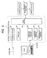
- Fig. 5 is a block diagram showing the internal structure of the external I/F processing portion 4 and the relation between the external I/F processing portion 4 and a peripheral apparatus.
- the external I/F processing portion 4 introduces the image data from a reader portion 1 through the image memory portion 3, and sends the image memory portion 3, and sends the image data to an external computer or an external facsimile apparatus through the network or a phone line. Also, the external I/F processing portion 4 outputs the image data sent from the external computer or facsimile apparatus through the network on the phone line to the printer portion 2 through the image memory portion 3 (and the image processing portion 170).
- the printer portion 2 effects image forming on the basis of the image data.
- the external I/F processing portion 4 is comprised of a core portion 506, a facsimile portion 501, a hard disk 502 for preserving the communication image data of the facsimile portion 501 therein, a computer interface portion 503 connected to the external computer 11, a formatter portion 504 and an image memory portion 505.
- the facsimile portion 501 is connected to a public line through a modem (not shown), and effects the reception of facsimile communication data from the public line, and the transmission of the facsimile communication data to the public line.
- the facsimile function of effecting FAX communication at a designated time, or transmitting the image data in accordance with an inquiry by a designated password from a partner is realized by the utilization of an image for FAX preserved in the hard disk 502.
- facsimile transmission can be effected without the reader portion 1 and the image memory portion 3 being used for the facsimile function.
- the computer interface portion 503 is an interface portion for effecting data communication with the external computer 11, and has a local area network (LAN), a serial I/F, a SCSI-I/T, a Centro I/F for the data inputting of the printer, etc.
- the external I/F processing portion 4 effects the notification of the states of the printer portion 2 and the reader portion 1 to the external computer 11 through the computer interface portion 503. Or the external I/F processing portion 4 forwards an image read by the reader portion 1 to the external computer 11 through the computer interface portion 503 on the basis of instructions from the external computer 11.
- the computer interface portion 503 receives print image data from the external computer 11.
- the print image data notified from the external computer 11 is described in a printer code for exclusive use and therefore, in the formatter portion 504, the notified data code is converted into raster image data which can effect image forming in the printer portion 2.
- the converted raster image data is evolved into the image memory portion 505 by the formatter portion 504.
- the formatter 504 effects, in the image memory portion 404, density conversion and conversion into an image format recognizable by the external computer 11 on the print image data sent from the image memory portion 3.
- the core portion 506 controls the forwarding of the data mutually effected among the facsimile portion 501, the computer interface portion 503, the formatter portion 504, the image memory portion 505 and the image memory portion 3. Thereby, even if a plurality of image output portions are connected to the external I/F processing portion 4 and even if the number of the image forwarding paths to the image memory portion 3 is one, the external I/F processing portion 4 can effect exclusive control and control of the degree of priority under the custody of the core portion 506 and can effect image outputting appropriately.
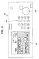
- Fig. 6 is a plan view of the operating portion 203 of the image forming apparatus.
- a display portion 3001 is adapted to display various messages such as the operating state of the apparatus and work instructions to the user, the working procedure, etc.
- the surface of the display portion 3001 is constituted by a touch panel, and is adapted to work as a selection key by being touched.
- Ten keys 3002, when depressed, are adapted to cause the image forming system 1000 to start the copying operation.
- the sheet supplying apparatus 1002 is connected to the main body 100 of the image forming apparatus 1001.
- the sheet supplying apparatus 1002 is constituted by four sheet decks 1200 (1200a to 1200d) of large capacity connected in series.
- As different sheets there are the difference in sheet size, the difference in the material of the sheets, the difference in the thickness of the sheets, the difference as to whether the sheets are colored or not, etc.
- the sheet decks 1200a, 1200b, 1200c and 1200d on the downstream side are referred to as the first, second, third and fourth sheet decks in the named order.
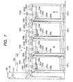
- the sheet decks 1200a to 1200d of the sheet supplying apparatus 1002 are provided with lifters 1201a to 1201d which are sheet stacking means for stacking the sheets thereon and lifting them, sheet supplying rollers 1202a to 1202d which are sheet supplying means for receiving the uppermost ones of the sheets lifted by the lifters and feeding out those sheets, sheet conveying paths 1205a to 1205d which are sheet conveying paths for guiding the sheets, joining paths 1206a to 1206d which are joining conveying paths for guiding the sheets fed out by the sheet supplying rollers to the sheet conveying paths, conveying rollers 1203a to 1203d and 1204a to 1204d which are sheet conveying means for conveying the sheets to the downstream side, sheet detecting sensors 1207a to 1207d which are sheet detecting means for detecting the passage of the sheets, sheet detecting sensors 1209a to 1209d for detecting that the sheets have been fed out from the sheet decks, remaining amount detecting sensors, not shown, for detecting the sheet remaining amounts, etc.
- the sheet detecting sensors 1207a to 1207d are disposed on the upstream side, preferably near the upstream side, of the joining points 1208a to 1208d between the joining paths 1206a to 1206d and the sheet conveying paths 1205a to 1205d.
- the sheet detecting sensors 1209a to 1209d are disposed near the joining points 1208a to 1208d, and are adapted to detect that the sheets have begun to be fed out from the joining points, and that the sheets have been fed out.
- the second sheet deck 1200b to the fourth sheet deck 1200d are adapted to feed out the sheets by the sheet supplying rollers 1202b to 1202d, and supply them to the image forming apparatus main body 100 by the guide by the joining paths 1206b to 1206d and the sheet conveying paths 1205a to 1205c, and the conveyance by the conveying rollers 1203a to 1203c and 1204a to 1204c.
- the sheets in the first sheet deck 1200a disposed on the most downstream side are supplied to the image forming apparatus main body 100 by the feeding-out by the sheet supplying roller 1202a and the guide by the joining path 1206a. Also, the sheet conveying path 1205d and conveying rollers 1203d and 1204d of the fourth sheet deck 1200d disposed on the most upstream side are used when a sheet deck is further connected on the upstream side.
- the sheets picked up by the sheet deck on the upstream side are adapted to be successively conveyed from there on the sheet conveying paths of the sheet decks on the downstream side and be finally supplied to the image forming apparatus main body.
- the conveying rollers of this sheet conveying path are adapted to continue the conveying operation even if the user opens the sheet decks to supply the sheets to the sheet decks information such as 1200.
- design is made such that the sizes and materials of the sheets stored in the sheet decks can be set by the operating portions 2206a to 2206d (see Figs. 2 and 7) which will be described later.
- Design may be made such that the information regarding the sheets can also be inputted from the operating portion 203 (see Figs. 2 and 6) of the image forming apparatus 1001.
- the number of the sheet decks connected is not limited, and further, the order of the connection can also be changed.
- the controlling portion will now be described with reference to Figs. 2 and 7.
- the sheet decks 1200a to 1200d are provided with controlling portions 2200a to 2200d.
- the controlling portion 2200a provided in the first sheet deck 1200a will be described and the showing and description of the other controlling portions 2200b to 2200d will be omitted. Therefore, reference characters to be given to constituent elements in the respective controlling portions are given in accordance with the alphabet characters of the sheet decks 1200a to 1200d.
- a ROM 2202a having a control program written thereinto, a work RAM 2203a for carrying out processing, and an input/output port 2205a are connected to a CPU 2201a for effecting basic control, by an address bus and a data bus.
- the area of a part of the RAM 2203b is a backup RAM from which data is not erased even if a power supply is cut off.
- the input/output port 2205a has connected thereto various load devices such as a motor and a clutch controlled by the CPU 2201a, and an input device to the CPU 2201a, such as a sensor for detecting the position of the sheet.
- the CPU 2201a has an operating portion 2206a connected thereto.
- the CPU 2201a is adapted to control the display means and key input means of the operating portion 2206a.
- the CPU 2201a is adapted to cause the display means of the operating portion 2206 to display the kind and size of the sheets set by a key input.
- the CPU 2201a is adapted to successively effect the control of an input and an output through the input/output port 2205a in accordance with the contents of the control program of the ROM 2202a to thereby execute the sheet separating and conveying processes correspondingly to a command from the image forming apparatus 1001.
- the CPU 201 (see Fig. 2) of the image forming apparatus 1001 and the CPU 2201a of the sheet deck 1200a are adapted to effect the exchanges of information with the image forming apparatus 1001 and the sheet deck 1200a by communication Ifs 207 and 2204a.
- the controlling portion 210 is a main controlling portion, and the controlling portions 2200a to 2200d are sub-controlling portions. These controlling portions 210 and 2200a to 2200a together constitute controlling means.
- the portion for controlling the sheet supplying apparatus 1002 may be provided in any one of he sheet decks 1200. Preferably, it may be provided in the sheet deck 1200a on the most downstream side.
- the controlling portions 2200a to 2200d of the respective sheet decks may be provided in the respective sheet decks, or may be provided any one sheet deck.
- the controlling portions are provided in any one sheet deck, it is preferable that they be provided in the first sheet deck 1200a with the changing of the number of the connected sheet decks taken into account.
- the user inputs the kind and number of sheets on which images are formed to the operating portion 203 of the image forming apparatus main body 100.
- the CPU 201 of the controlling portion 210 of the image forming apparatus main body 100 transmits the kind information of the sheets inputted by the user to the controlling portions 2200a to 2200d of the sheet decks 1200a to 1200d. Assuming that sheets coinciding the sheet information are stacked, for example, on the fourth sheet deck 1200d on the most upstream side (the rightest side in Fig. 7), the CPU 2201d of the controlling portion 2200d of the fourth sheet deck 1200d starts sheet supply control and operates the sheet feeding roller 1202d, etc. The sheet is fed out from the fourth sheet deck 1200d via the joining path 1206d.
- the sheet must pass through the sheet conveying paths 1205c, 1205b and 1205a of the third sheet deck 1200c, the second sheet deck 1200b and the first sheet deck 1200a, respectively, on the downstream side.
- the controlling portion 2200d of the fourth sheet deck 1200d instructs the controlling portions 2200c, 2200b and 2200a of the sheet decks 1200c, 1200b and 1200a, respectively, on the downstream side to rotate the conveying rollers 1204c, 1203c, 1204b, 1203b, 1204a and 1203a.
- the sheets designated by the user are prevented from being double fed and only a designated number of sheets are fed to the image forming apparatus main body 100.
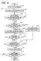
- the description of the pre-feeding operation will now be made with reference to Figs. 1, 2, 7 and 8.
- the user inputs the information of two kinds of sheets on which images are formed to the operating portion 203 of the image forming apparatus main body 100 in the order of image forming. For example, it is to be understood that input information is repeated in the order of B-sheet and A-sheet to thereby form images on the sheets.
- the CPU 201 of the controlling portion 210 of the image forming apparatus main body 100 instructs the controlling portion 2200b of the second sheet deck 1200b stacking the B-sheets thereon and the controlling portion 1200d of the fourth sheet deck 1200d stacking the A-sheets thereon to supply the sheets.
- the second sheet deck 1200b and the fourth sheet deck 1200d become ready to supply the sheets (step 101).
- the step will hereinafter be abbreviated as "S.”
- the controlling portion 2200d of the fourth sheet deck 1200d inquires the controlling portions 2200a to 2200c of the remaining three sheet decks 1200a to 1200c about which sheet deck is the sheet deck on which the preceding B-sheets are stacked.
- the controlling portion 2200b of the second sheet deck 1200b notifies the controlling portion 2200d of the fourth sheet deck 1200d that the B-sheets are stacked on the second sheet deck 1200b.
- the controlling portion 2200d of the fourth sheet deck 1200d can know that the B-sheets are stacked on the second sheet deck 1200b.
- the B-sheets in the second sheet deck 1200b on the downstream side are supplied earlier than the A-sheets in the fourth deck 1200d on the upstream side and therefore, the sheet conveying distance of the fourth sheet deck 1200d is longer than the sheet conveying distance of the second sheet deck 1200b, and when the fourth sheet deck 1200d on the upstream side is started and feeds out the succeeding A-sheet after the feeding-out of the preceding B-sheet from the second sheet deck 1200b on the downstream side, the interval between the preceding B-sheet on the downstream side and the succeeding A-sheet on the upstream side widens, and the supply of the A-sheet to the image forming apparatus main body 100 is delayed.
- the fourth sheet deck 1200d which has known that the B-sheet is supplied from the second sheet deck 1200b conveyance-controls the A-sheet to the vicinity of the joining point 1208b of the second sheet deck 1200b while the B-sheet is fed out from the second sheet deck 1200b on the downstream side, and causes it to wait, the interval of the A-sheet relative to the B-sheet can be made into a predetermined interval to thereby supply the A-sheet to the image forming apparatus main body 100.
- the controlling portion 2200d of the fourth sheet deck 1200 when it knows by the aforedescribed operation that the B-sheets are supplied from the second sheet deck 1200b, starts the supply of the A-sheets (S103) and also, instructs the controlling portions 2200c and 2200b on the downstream side to rotate the conveying rollers 1203c, 1203b, 1204c and 1204b.
- the A-sheet on the upstream side arrives at the sheet detecting sensor 1207b disposed near the upstream side of the joining point 1208b in the second sheet deck 1200b (S105) and is detected.
- the A-sheet is detected at the position of the sheet detecting sensor 1207b of the second sheet deck 1200b and stands by (S109). That is, the A-sheet has been pre-fed. After it is detected by the sheet detecting sensor 1209b that the B-sheet has passed the joining point 1208b in the second sheet deck 1200b and has been completely fed out from the second sheet deck 1200b (S111), when the interval between the B-sheet and the A-sheet becomes a predetermined interval (S113), the conveyance of the A-sheet is resumed (S115).
- the A-sheet stops and waits at the position of the sheet detecting sensor 1207b of the second sheet deck (S119). That is, the A-sheet has been pre-fed. Then, when the interval between the B-sheet and the A-sheet becomes a predetermined interval (S113), the conveyance of the A-sheet is resumed (S115).
- the second A-sheet is fed out from the fourth sheet deck 1200d, and is pre-fed. Thereafter, in the same manner as described above, the conveyance of the B-sheets and the A-sheets is effected.
- the sheet supplying operation of the sheet supplying apparatus 1002 is stopped.
- the feed timing from the fourth sheet deck 1200d is set so that the A-sheet may be conveyed to the image forming apparatus with a predetermined interval kept relative to the B-sheet.
- design is made such that the A-sheet is fed out from the fourth sheet deck at the timing whereat the A-sheet arrives at the sheet detecting sensor 1209b while the B-sheet is fed out from the second sheet deck 1200b.
- the predetermined interval refers to an interval at which in the image forming apparatus, an image can be efficiently and accurately formed on a sheet, or an interval at which in the sheet supplying apparatus 1002, a sheet can be conveyed efficiently.
- each sheet deck in the above-described embodiment has one of the lifters 1201a to 1201d, but in some cases it is provided with multiple stages of lifters.
- the sheet deck provided with multiple stages of lifters be designed such that when other sheet is passing through this sheet deck, the sheet in this sheet deck is conveyed in advance to the joining point or to the vicinity thereof.
- the sheet supplying apparatus 1002 of the present embodiment conveys sheets to the image forming apparatus main body by repeating the order of B-sheet, A-sheet, B-sheet and A-sheet, but even if he fourth sheet deck 1200d on which the A-sheets are stacked is far toward the upstream side from the second sheet deck 1200b on which the preceding B-sheets are stacked, design is made such that the succeeding A-sheets on the upstream side are pre-fed and therefore, the succeeding A-sheet can be conveyed with the predetermined interval kept relative to the preceding B-sheet until it is nipped between the registration rollers 137, whereby the image forming apparatus 1001 is enabled to form images on the sheets without showing down the speed of continuous printing.
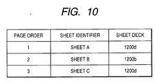
- the sheet supplying order is such that as shown, for example, in the table of Fig. 10, the operation of first supplying A-sheet from the fourth sheet deck 1200d on the upstream side, and then supplying B-sheet from the second sheet deck 1200b on the downstream side, and again supplying C-sheet from the fourth sheet deck 1200d is repeated. That is, design is made such that a predetermined number of sheets are supplied by repeating the order of A-sheet, B-sheet, C-sheet, A-sheet, B-sheet, C-sheet, ⁇ .
- the fourth sheet deck 1200d is adapted to stack A-sheets and C-sheets thereon, but this is for making the description of the operation easily understood, and the C-sheets are the same as the A-sheets, and only the A-sheets are stacked on the fourth sheet deck 1200d.
- the sheets are supplied by repeating the order of A-sheet, B-sheet, A-sheet, B-sheet, A-sheet, ⁇ .
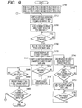
- an A-sheet and C-sheet pre-feed command is issued from the controlling portion 210 of the image forming apparatus main body 100 to the controlling portion 2200d of the fourth sheet deck 1200d, and a B-sheet pre-feed command is issued to the controlling portion 2200b of the second sheet deck 1200b (S700).
- the controlling portion 210 also issues a feed order command to the controlling portions 2200d and 2200b so as to feed the sheets by repeating the order of A-sheet, B-sheet, C-sheet.
- the controlling portion 2200d of the fourth sheet deck 1200d which has received the A-sheet pre-feed command immediately starts the sheet supplying roller 1202d to thereby start the feeding of the A-sheet (S710).
- the controlling portion 2200b of the second sheet deck 1200b when it receives the B-sheet pre-feed command, effects an inquiry as to flow which sheet deck the A-sheet which must be located before the B-sheet is supplied, and when it is judged to be from the fourth sheet deck 1200d, whether the A-sheet fed out from the fourth sheet deck 1200d has passed through the second sheet deck 1200b is judged (S720). The judgment is effected on the basis of the sheet detection by the sheet detecting sensor 1207b in the second sheet deck 1200b.
- the B-sheet feeding operation is started from the second sheet deck 1200b (S730). If conversely, the result of the judgment is "the A-sheet has not yet passed,” the controlling portion 2200b of the second sheet deck 1200b transmits a command for issuing a request to notify of the arrival of the sheet to the controlling portion 2200c of the third sheet deck 1200c located upstream of the second sheet deck 1200b (S740). The second sheet deck 1200b stops the feeding-out of the sheet until the notification of the arrival of the A-sheet to the third sheet deck 1200c transmitted at S740 by the second sheet deck 1200b is sent thereto (the waiting process of the B-sheet is effected) (S750).
- the second sheet deck 1200b When the second sheet deck 1200b receives the notification of the arrival of the A-sheet from the third sheet deck 1200c (S751) and the sheet detecting sensor 1207b detects the passage of the sheet and it is detected that the A-sheet has passed through the second sheet deck 1200b (S752), the second sheet deck 1200b starts the feeding of the B-sheet (S730). In this case, the B-sheet may be fed in advance to the vicinity of the joining point 1208b.
- the controlling portion 2200d of the fourth sheet deck 1200d which has received the C-sheet per-feed command inquires the controlling portions 2200a, 2200b and 2200c of the first sheet deck 1200a, the second sheet deck 1200b and the third sheet deck 1200c, respectively, to judge from which sheet deck located on the downstream side the B-sheet to be located before the C-sheet is supplied (S760).
- the controlling portion 2200d of the fourth sheet deck 1200d carries out the waiting process of the C-sheet until the result of the inquiry is returned from each sheet deck (S770).
- the controlling portion 2200d of the fourth sheet deck 1200d adjusts the interval of the C-sheet relative to the A-sheet (S790) and starts the control of feeding the C-sheet to a position at which it is detected by the sheet detecting sensor 1207b at the joining point 1208b of the second sheet deck 1200b (S800).
- the C-sheet fed subsequently to the A-sheet is stopped at the position of the sheet detecting sensor 1207b in the second sheet deck 1200b and waits for the B-sheet to go out of the second sheet deck 1200b (S840).
- the second sheet deck 1200b resumes the feeding of the C-sheet so far stopped (S850).
- the sheets have been supplied from the sheet decks 1200 to the image forming apparatus main body 100 in the order of A-sheet, B-sheet and C-sheet, and the above-described operation is repeated until a predetermined number of sheets are supplied to the image forming apparatus main body 100 (S860).
- the sheet supplying apparatus 1002 of the present embodiment can effect the pre-feeding in which, even if the fourth sheet deck 1200d on which the C-sheets (substantially the same as the A-sheets) are stacked is for toward the upstream side from the second sheet deck 1200b on which the preceding B-sheets are stacked, when the A-sheet has been fed out from the fourth sheet deck 1200d, subsequently to the A-sheet, the C-sheet is also fed out from the fourth sheet deck 1200d, and the C-sheet is stopped at the position of the sheet detecting sensor 1207b of the second sheet deck 1200b, and is made to wait at that position until the B-sheet is fed out from the second sheet deck 1200b, and therefore enables the succeeding C-sheet to be conveyed at a predetermined interval relative to the preceding B-sheet until it is nipped between the registration rollers 137, and enables the image forming apparatus 100 to form images on the sheets without slowing down the speed of continuous printing.
- the supply order of sheets is such that first, the A-sheet is supplied from the third sheet deck 1200c, and then the B-sheet is supplied from the second sheet deck 1200b on the downstream side, and the C-sheet is supplied from the fourth sheet deck 1200d.
- a predetermined number of sheets are supplied by repeating the order of A-sheet, B-sheet, C-sheet, A-sheet, B-sheet, C-sheet, ⁇ . That is, description will be made of a case where in contrast with the above-described embodiment, the A-sheet, the B-sheet and the C-sheet are supplied from different sheet decks, respectively.
- an A-sheet pre-feed command is issued from the controlling portion 210 of the image forming apparatus main body 100 to the controlling portion 2200c of the third sheet deck 1200c, a B-sheet pre-feed command is issued to the controlling portion 2200b of the second sheet deck 1200b, and a C-sheet pre-feed command is issued to the controlling portion 2200d of the fourth sheet deck 1200d.
- the controlling portion 210 also issues a feed order command to the controlling portions 2200b to 2200d so as to feed the sheets by repeating the order of A-sheet, B-sheet and C-sheet.
- the controlling portion 2200c of the third sheet deck 1200c which has received the A-sheet pre-feed command immediately starts the sheet supplying roller 1202c to thereby start the feeding of the A-sheet.
- the controlling portion 2200b of the second sheet deck 1200b when it receives the B-sheet pre-feed command, effects an inquiry as to from which sheet deck the A-sheet which must be located before the B-sheet is supplied, and if it is judged to be from the third sheet deck 1200c, whether the A-sheet fed out from the third sheet deck 1200c has passed through the second sheet deck 1200b is judged. The judgment is effected on the basis of the sheet detection by the sheet detecting sensor 1207b in the second sheet deck 1200b.
- the B-sheet feeding operation is started from the second sheet deck 1200b. If conversely, the result of the judgment is "the A-sheet has not yet passed,” the controlling portion 2200b of the second sheet deck 1200b starts the feeding of the B-sheet when the sheet detecting sensor 1207b detects the passage of the sheet and it is detected that the A-sheet has passed through the second sheet deck 1200b. In this case, the B-sheet may be fed in advance to the vicinity of the joining point 1208b.
- the controlling portion 2200d of the fourth sheet deck 1200d which has received the C-sheet pre-feed command inquires the controlling portions 2200a, 2200b and 2200c of the first sheet deck 1200a, the second sheet deck 1200b and the third sheet deck 1200c, respectively, to judge from which sheet deck located on the downstream side the A-sheet and the B-sheet to be located before the C-sheet join.
- the controlling portion 2200d of the fourth sheet deck 1200d carries out the C-sheet waiting process until the result of the inquiry is returned from each sheet deck.
- the controlling portion 2200d of the fourth sheet deck 1200d recognizes that the sheet deck for supplying the A-sheet is the third sheet deck 1200c and that the sheet deck for supplying the B-sheet is the second sheet deck 1200b, and starts the control of conveying the C-sheet to a position at which it is detected by the sheet detecting sensor 1207b at the joining point 1208c of the third sheet deck 1200c which is the most downstream position which does not hinder the supply of the preceding sheet.
- the C-sheet is stopped at the position of the sheet detecting sensor 1207c in the third sheet deck 1200c and waits for the A-sheet to go out form the third sheet deck 1200c.
- the C-sheet is further fed to the position of the sheet detecting sensor 1207b in the second sheet deck 1200b.
- the A-sheet passes through the second sheet deck 1200b, and the B-sheet is fed out from the second sheet deck 1200b, and it is detected by the sheet detecting sensor 1209b that this B-sheet has been fed out, the second sheet deck 1200b resumes the conveyance of the C-sheet so far stopped.
- the sheets are supplied form the sheet deck 1200 to the image forming apparatus main body 100 in the order of A-sheet, B-sheet and C-sheet, and the above-described operation is repeated until a predetermined number of sheets are supplied to the image forming apparatus main body 100.
- the sheet decks 1200a to 1200d it becomes possible for the sheet decks 1200a to 1200d to recognize the sheet deck on which the sheets to be fed earlier are stacked, and control so as to pre-feed the stacked sheets to this side of the joining point of that sheet deck, to thereby supply the sheets to the image forming apparatus main body 100 at a short inter-sheet interval even when a number of sheet decks are connected together, and the image forming apparatus 1001 is enabled to form images on the sheets without slowing down the speed of continuous printing.
- each sheet deck supplies sheets in order, it becomes possible for each sheet deck to judge the sheet deck stacking thereon sheets preceding its own sheets in order, and pre-feed its own sheets to the joining point of the sheets in that judges sheet deck to thereby shorten the distance to the preceding sheet, and the sheets can be supplied to the image forming apparatus with the inter-sheet interval shortened to thereby improve productivity.
- the position at which the pre-fed sheet waits is a position detected by the sheet detecting sensors 1207a to 1207d
- the present invention is not restricted thereto.
- the number of revolutions of the conveying rollers 1203a to 1203c or the conveying rollers 1204a to 1204c, or the number of revolutions of a motor for rotating those rollers may be detected by an encoder or a pulse counter.
- design may be made such that the position of the sheet is detected by the number of revolutions of the rollers or the motor.
- the sheet decks are to be connected in series to the image forming apparatus main body 100, if the sheet decks are connected to the image forming apparatus main body 100 in the order from the sheet deck which feeds out the sheets more frequently, it will never happen that the other sheet decks are operated unnecessarily, and the sheet decks can be used for a long period.
- a sheet supplying apparatus having a plurality of sheet decks for supplying sheets connected in series, and provided with a controller for controlling the feeding of the sheets of each sheet deck, wherein each sheet deck has a sheet stacking portion for supporting the sheets thereon, a sheet conveying path for guiding the sheets from an upstream side to a downstream side, and a joining conveying path joining the sheet conveying path for guiding the sheets from the sheet stacking portion to the sheet conveying path, wherein the sheet decks are connected in such a manner that the respective sheet conveying paths are connected thereto, and the controller judges the position of the sheet deck for supplying a sheet preceding by one the sheet supplied in predetermined order when the sheets are supplied in order from each sheet deck and controls so as to pre-feed the sheet in the predetermined order to the vicinity of the upstream side of a joining point between the sheet conveying path in the sheet deck for supplying the preceding sheet and the joining conveying path when the judged sheet deck is disposed downstream of the sheet deck for supplying the sheet in the predetermined order.
Landscapes
- Physics & Mathematics (AREA)
- General Physics & Mathematics (AREA)
- Sheets, Magazines, And Separation Thereof (AREA)
- Paper Feeding For Electrophotography (AREA)
- Facsimiles In General (AREA)
Applications Claiming Priority (2)
| Application Number | Priority Date | Filing Date | Title |
|---|---|---|---|
| JP2003356361A JP4235528B2 (ja) | 2003-10-16 | 2003-10-16 | シート供給装置及び画像形成システム |
| JP2003356361 | 2003-10-16 |
Publications (3)
| Publication Number | Publication Date |
|---|---|
| EP1524562A2 true EP1524562A2 (fr) | 2005-04-20 |
| EP1524562A3 EP1524562A3 (fr) | 2011-11-30 |
| EP1524562B1 EP1524562B1 (fr) | 2012-12-12 |
Family
ID=34373593
Family Applications (1)
| Application Number | Title | Priority Date | Filing Date |
|---|---|---|---|
| EP04024547A Expired - Lifetime EP1524562B1 (fr) | 2003-10-16 | 2004-10-14 | Appareil d'alimentation de feuilles et système de formation d'image |
Country Status (4)
| Country | Link |
|---|---|
| US (1) | US7380780B2 (fr) |
| EP (1) | EP1524562B1 (fr) |
| JP (1) | JP4235528B2 (fr) |
| CN (2) | CN1326710C (fr) |
Cited By (1)
| Publication number | Priority date | Publication date | Assignee | Title |
|---|---|---|---|---|
| EP1972580A3 (fr) * | 2007-03-19 | 2009-12-30 | Konica Minolta Business Corporation, Inc. | Appareil d'alimentation de feuilles |
Families Citing this family (23)
| Publication number | Priority date | Publication date | Assignee | Title |
|---|---|---|---|---|
| US7283759B2 (en) * | 2004-03-31 | 2007-10-16 | Canon Kabushiki Kaisha | Image forming apparatus with heating member control in accordance with type of recording material |
| US7669844B2 (en) * | 2004-04-26 | 2010-03-02 | Sharp Kabushiki Kaisha | Paper feeder |
| JP4402508B2 (ja) * | 2004-04-28 | 2010-01-20 | キヤノン株式会社 | 画像形成装置 |
| JP4115989B2 (ja) * | 2004-12-15 | 2008-07-09 | シャープ株式会社 | 画像形成装置 |
| JP4939123B2 (ja) * | 2005-08-31 | 2012-05-23 | キヤノン株式会社 | シート搬送装置とシート後処理装置及びそれらを備えた画像形成装置 |
| JP4684814B2 (ja) * | 2005-09-06 | 2011-05-18 | キヤノン株式会社 | 画像形成装置 |
| US7556254B2 (en) * | 2005-11-25 | 2009-07-07 | Canon Kabushiki Kaisha | Image forming system and paper feeder thereof |
| JP4895369B2 (ja) * | 2006-09-08 | 2012-03-14 | キヤノン株式会社 | 設計支援方法、設計支援装置、設計支援プログラム、記憶媒体 |
| JP2008077356A (ja) * | 2006-09-20 | 2008-04-03 | Canon Inc | 設計支援方法、設計支援装置、設計支援プログラム、記憶媒体 |
| JP5159217B2 (ja) * | 2006-09-25 | 2013-03-06 | キヤノン株式会社 | 画像形成装置 |
| JP4912166B2 (ja) * | 2007-01-24 | 2012-04-11 | キヤノン株式会社 | 印刷システム及びその制御方法 |
| US8052144B2 (en) * | 2007-08-07 | 2011-11-08 | Ricoh Company, Ltd. | Method, apparatus, and system for forming image |
| DE112008003750T5 (de) | 2008-02-29 | 2010-12-30 | Hewlett-Packard Development Co., L.P., Houston | Systeme und Verfahren zum Drucken unter Verwendung verketteter Medienzufuhrvorrichtungen |
| JP4513883B2 (ja) * | 2008-03-25 | 2010-07-28 | 富士ゼロックス株式会社 | 媒体供給装置および画像形成装置 |
| JP5450998B2 (ja) * | 2008-07-23 | 2014-03-26 | キヤノン株式会社 | 画像形成装置 |
| IT1394149B1 (it) * | 2008-09-12 | 2012-05-25 | Panotec Srl | Apparecchiatura per il caricamento di un materiale relativamente rigido, ad esempio cartone, e relativo procedimento di caricamento |
| JP2010111062A (ja) * | 2008-11-07 | 2010-05-20 | Fuji Xerox Co Ltd | 画像形成システムおよびプログラム |
| JP5120470B2 (ja) * | 2011-02-10 | 2013-01-16 | 富士ゼロックス株式会社 | 給紙装置及び画像形成システム |
| DE102011016105A1 (de) * | 2011-04-05 | 2012-10-11 | Eastman Kodak Company | Verfahren zum Einspeisen von Bögen |
| JP2015124028A (ja) * | 2013-12-25 | 2015-07-06 | 株式会社沖データ | 画像形成装置 |
| WO2018002942A1 (fr) * | 2016-06-27 | 2018-01-04 | Hewlett-Packard Development Company, L.P. | Commande de bac d'impression sur la base d'une entrée d'utilisateur |
| JP6702252B2 (ja) * | 2017-04-20 | 2020-05-27 | 京セラドキュメントソリューションズ株式会社 | 画像形成装置 |
| JP7214994B2 (ja) * | 2018-07-04 | 2023-01-31 | 京セラドキュメントソリューションズ株式会社 | 画像形成装置 |
Citations (2)
| Publication number | Priority date | Publication date | Assignee | Title |
|---|---|---|---|---|
| US5383654A (en) | 1990-07-23 | 1995-01-24 | Kabushiki Kaisha Toshiba | Paper sheet feeder |
| JP2001039552A (ja) | 1999-07-30 | 2001-02-13 | Canon Inc | プリント装置 |
Family Cites Families (38)
| Publication number | Priority date | Publication date | Assignee | Title |
|---|---|---|---|---|
| US4796035A (en) * | 1984-11-30 | 1989-01-03 | Canon Kabushiki Kaisha | Image recording apparatus with improved system for feeding and exhausting recording sheets |
| JP2584471B2 (ja) | 1988-02-15 | 1997-02-26 | 株式会社リコー | システムプリンタ |
| JPH0745291B2 (ja) * | 1989-05-15 | 1995-05-17 | シャープ株式会社 | 給紙装置 |
| US5072924A (en) * | 1989-05-29 | 1991-12-17 | Mita Industrial Co., Ltd. | Paper feeding control device |
| US5258779A (en) * | 1990-02-17 | 1993-11-02 | Canon Kabushiki Kaisha | Image forming apparatus with means for controlling feeding of recording medium |
| JP2840499B2 (ja) * | 1992-05-13 | 1998-12-24 | キヤノン株式会社 | 自動給紙装置及び画像読取装置 |
| US5290024A (en) * | 1991-06-28 | 1994-03-01 | Canon Kabushiki Kaisha | Automatic sheet feeding apparatus |
| EP0761581B1 (fr) * | 1995-08-28 | 2003-05-02 | Canon Kabushiki Kaisha | Dispositif d'alimentation de feuilles |
| US5592881A (en) * | 1995-08-28 | 1997-01-14 | Xerox Corporation | System for identifying modules in a modular printing apparatus |
| JP2723864B2 (ja) * | 1995-11-20 | 1998-03-09 | 日本電気ロボットエンジニアリング株式会社 | 紙葉類の重ね合わせ機構 |
| JPH09263341A (ja) * | 1996-03-26 | 1997-10-07 | Canon Inc | 印刷装置、印刷方法及び印刷システム |
| US5909591A (en) * | 1996-06-18 | 1999-06-01 | Lucent Technologies Inc. | System and method for identifying individual modules in a modular system |
| CA2269576A1 (fr) | 1996-10-22 | 1998-04-30 | Oce Printing Systems Gmbh | Dispositif d'alimentation en papier pour imprimante de feuilles seules |
| US5764369A (en) * | 1997-03-27 | 1998-06-09 | Xerox Corporation | Method for determining port pairings of machine modules |
| US6806972B1 (en) * | 1998-01-08 | 2004-10-19 | Xerox Corporation | Customer product installation/configuration |
| JP3463915B2 (ja) * | 1998-02-19 | 2003-11-05 | 株式会社リコー | 給紙装置 |
| JPH11255419A (ja) * | 1998-03-11 | 1999-09-21 | Canon Inc | シート穴空け装置及び画像形成装置 |
| GB2342091B (en) * | 1998-09-30 | 2002-10-23 | Xerox Corp | Sheet feed assembly |
| US6148172A (en) * | 1998-10-09 | 2000-11-14 | Konica Corporation | Image forming apparatus having means for enhancing accuracy of conveyance of recording sheets |
| JP2000118783A (ja) * | 1998-10-16 | 2000-04-25 | Canon Inc | 画像形成装置 |
| US6311039B1 (en) * | 1998-10-26 | 2001-10-30 | Canon Kabushiki Kaisha | Sheet conveying apparatus and image forming apparatus provided with the same |
| JP3682836B2 (ja) * | 1998-10-30 | 2005-08-17 | リコープリンティングシステムズ株式会社 | 画像形成装置 |
| EP1006709B1 (fr) * | 1998-11-30 | 2006-05-10 | Canon Kabushiki Kaisha | Traitement de formation d'image avec fonction de rotation d'image |
| US6322069B1 (en) * | 1999-03-12 | 2001-11-27 | Xerox Corporation | Interpaper spacing control in a media handling system |
| JP2001301998A (ja) * | 2000-02-15 | 2001-10-31 | Canon Inc | シート搬送装置及びこれを備えた画像形成装置並びに画像読取装置 |
| US6651980B2 (en) * | 2001-06-13 | 2003-11-25 | Canon Kabushiki Kaisha | Sheet conveying apparatus with correction device to compensate for sheet interval variation |
| US6804474B2 (en) * | 2001-07-24 | 2004-10-12 | Canon Kabushiki Kaisha | Image forming apparatus |
| US6826374B2 (en) * | 2001-08-31 | 2004-11-30 | Canon Kabushiki Kaisha | Sheet processing apparatus with discharge sheet cover and control based on open/close state of cover |
| US6782236B2 (en) * | 2001-10-02 | 2004-08-24 | Canon Kabushiki Kaisha | Duplex image forming apparatus |
| JP3753063B2 (ja) * | 2001-12-20 | 2006-03-08 | ブラザー工業株式会社 | 画像形成装置 |
| US6836640B2 (en) * | 2001-12-12 | 2004-12-28 | Canon Kabushiki Kaisha | Sheet conveying apparatus and image forming apparatus |
| JP3768965B2 (ja) * | 2002-04-01 | 2006-04-19 | キヤノン株式会社 | シート処理装置及び該装置を備えた画像形成装置 |
| JP4261826B2 (ja) * | 2002-06-12 | 2009-04-30 | キヤノン株式会社 | 画像形成装置 |
| CN100382073C (zh) * | 2003-03-27 | 2008-04-16 | 佳能株式会社 | 图像形成系统、图像形成系统的控制方法 |
| US7237772B2 (en) * | 2003-05-01 | 2007-07-03 | Canon Kabushiki Kaisha | Image forming apparatus with control of sheet carrier to compensate for sheet conveying distance |
| JP2005306559A (ja) * | 2003-10-01 | 2005-11-04 | Konica Minolta Business Technologies Inc | 用紙後処理装置 |
| US7255337B2 (en) * | 2003-10-01 | 2007-08-14 | Konica Minolta Business Technologies, Inc. | Oscillating transport unit for post-processing device |
| JP4272969B2 (ja) * | 2003-10-16 | 2009-06-03 | キヤノン株式会社 | シート処理システム |
-
2003
- 2003-10-16 JP JP2003356361A patent/JP4235528B2/ja not_active Expired - Lifetime
-
2004
- 2004-10-08 US US10/960,091 patent/US7380780B2/en not_active Expired - Lifetime
- 2004-10-14 EP EP04024547A patent/EP1524562B1/fr not_active Expired - Lifetime
- 2004-10-15 CN CNB200410084186XA patent/CN1326710C/zh not_active Expired - Lifetime
- 2004-10-15 CN CNA2007101096162A patent/CN101063848A/zh active Pending
Patent Citations (2)
| Publication number | Priority date | Publication date | Assignee | Title |
|---|---|---|---|---|
| US5383654A (en) | 1990-07-23 | 1995-01-24 | Kabushiki Kaisha Toshiba | Paper sheet feeder |
| JP2001039552A (ja) | 1999-07-30 | 2001-02-13 | Canon Inc | プリント装置 |
Cited By (2)
| Publication number | Priority date | Publication date | Assignee | Title |
|---|---|---|---|---|
| EP1972580A3 (fr) * | 2007-03-19 | 2009-12-30 | Konica Minolta Business Corporation, Inc. | Appareil d'alimentation de feuilles |
| US7677549B2 (en) | 2007-03-19 | 2010-03-16 | Konica Minolta Business Technologies, Inc. | Sheet supplying apparatus |
Also Published As
| Publication number | Publication date |
|---|---|
| CN1608856A (zh) | 2005-04-27 |
| JP2005121886A (ja) | 2005-05-12 |
| CN101063848A (zh) | 2007-10-31 |
| US7380780B2 (en) | 2008-06-03 |
| EP1524562A3 (fr) | 2011-11-30 |
| JP4235528B2 (ja) | 2009-03-11 |
| EP1524562B1 (fr) | 2012-12-12 |
| CN1326710C (zh) | 2007-07-18 |
| US20050082737A1 (en) | 2005-04-21 |
Similar Documents
| Publication | Publication Date | Title |
|---|---|---|
| EP1524562B1 (fr) | Appareil d'alimentation de feuilles et système de formation d'image | |
| US7389084B2 (en) | Image forming system with temporary storage trays between sheet storage units and image forming apparatus | |
| JPH0822156A (ja) | 画像形成システム | |
| US7742180B2 (en) | Dust and/or dirt detection in image reading apparatus having read-while-feed function | |
| US6421523B1 (en) | Image forming apparatus capable of shift stacking discharged sheet bundle | |
| US6343197B1 (en) | Image formation processing having image rotation function | |
| JP4684814B2 (ja) | 画像形成装置 | |
| JP4469593B2 (ja) | 画像形成システムおよびその制御方法 | |
| JP4136821B2 (ja) | 画像形成システム | |
| JP4447984B2 (ja) | 速度変換ユニット及び画像形成装置 | |
| JP4378123B2 (ja) | 画像形成システム | |
| JP2005049392A (ja) | 画像形成システム | |
| JP2003110761A (ja) | 画像形成装置、その制御方法、及びその制御プログラムを格納したコンピュータにより読み取り可能な記憶媒体 | |
| JP2006111388A (ja) | 画像形成システム | |
| JP2005043615A (ja) | 画像形成システム | |
| JP3975707B2 (ja) | シート挿入装置及びシート挿入方法並びに該シート挿入装置を備えた後処理装置、画像形成システムとその制御方法 | |
| JPH10191031A (ja) | 画像形成装置及び画像形成方法 | |
| JP2005335164A (ja) | 画像形成装置および画像形成システム | |
| JP2003040517A (ja) | 画像形成装置 | |
| JPH10198104A (ja) | 画像形成装置 | |
| JP2006035444A (ja) | 画像形成システム | |
| JP2002185696A (ja) | 画像形成装置及び画像読取り方法 | |
| JP2005047629A (ja) | 画像形成システム | |
| JPH11240668A (ja) | 用紙排出装置および画像形成システム | |
| JP2000302322A (ja) | シート処理装置及びこれを備える画像形成装置 |
Legal Events
| Date | Code | Title | Description |
|---|---|---|---|
| PUAI | Public reference made under article 153(3) epc to a published international application that has entered the european phase |
Free format text: ORIGINAL CODE: 0009012 |
|
| AK | Designated contracting states |
Kind code of ref document: A2 Designated state(s): AT BE BG CH CY CZ DE DK EE ES FI FR GB GR HU IE IT LI LU MC NL PL PT RO SE SI SK TR |
|
| AX | Request for extension of the european patent |
Extension state: AL HR LT LV MK |
|
| 17P | Request for examination filed |
Effective date: 20051017 |
|
| PUAL | Search report despatched |
Free format text: ORIGINAL CODE: 0009013 |
|
| AK | Designated contracting states |
Kind code of ref document: A3 Designated state(s): AT BE BG CH CY CZ DE DK EE ES FI FR GB GR HU IE IT LI LU MC NL PL PT RO SE SI SK TR |
|
| AX | Request for extension of the european patent |
Extension state: AL HR LT LV MK |
|
| RIC1 | Information provided on ipc code assigned before grant |
Ipc: G03G 15/00 20060101AFI20111021BHEP |
|
| 17Q | First examination report despatched |
Effective date: 20111109 |
|
| GRAP | Despatch of communication of intention to grant a patent |
Free format text: ORIGINAL CODE: EPIDOSNIGR1 |
|
| AKX | Designation fees paid |
Designated state(s): DE FR GB IT |
|
| GRAS | Grant fee paid |
Free format text: ORIGINAL CODE: EPIDOSNIGR3 |
|
| GRAA | (expected) grant |
Free format text: ORIGINAL CODE: 0009210 |
|
| AK | Designated contracting states |
Kind code of ref document: B1 Designated state(s): DE FR GB IT |
|
| REG | Reference to a national code |
Ref country code: GB Ref legal event code: FG4D |
|
| REG | Reference to a national code |
Ref country code: DE Ref legal event code: R096 Ref document number: 602004040366 Country of ref document: DE Effective date: 20130207 |
|
| PLBE | No opposition filed within time limit |
Free format text: ORIGINAL CODE: 0009261 |
|
| STAA | Information on the status of an ep patent application or granted ep patent |
Free format text: STATUS: NO OPPOSITION FILED WITHIN TIME LIMIT |
|
| 26N | No opposition filed |
Effective date: 20130913 |
|
| REG | Reference to a national code |
Ref country code: DE Ref legal event code: R097 Ref document number: 602004040366 Country of ref document: DE Effective date: 20130913 |
|
| REG | Reference to a national code |
Ref country code: FR Ref legal event code: PLFP Year of fee payment: 12 |
|
| REG | Reference to a national code |
Ref country code: FR Ref legal event code: PLFP Year of fee payment: 13 |
|
| REG | Reference to a national code |
Ref country code: FR Ref legal event code: PLFP Year of fee payment: 14 |
|
| REG | Reference to a national code |
Ref country code: FR Ref legal event code: PLFP Year of fee payment: 15 |
|
| PGFP | Annual fee paid to national office [announced via postgrant information from national office to epo] |
Ref country code: IT Payment date: 20230920 Year of fee payment: 20 Ref country code: GB Payment date: 20230920 Year of fee payment: 20 |
|
| PGFP | Annual fee paid to national office [announced via postgrant information from national office to epo] |
Ref country code: FR Payment date: 20230920 Year of fee payment: 20 |
|
| PGFP | Annual fee paid to national office [announced via postgrant information from national office to epo] |
Ref country code: DE Payment date: 20230920 Year of fee payment: 20 |
|
| REG | Reference to a national code |
Ref country code: DE Ref legal event code: R071 Ref document number: 602004040366 Country of ref document: DE |
|
| REG | Reference to a national code |
Ref country code: GB Ref legal event code: PE20 Expiry date: 20241013 |
|
| PG25 | Lapsed in a contracting state [announced via postgrant information from national office to epo] |
Ref country code: GB Free format text: LAPSE BECAUSE OF EXPIRATION OF PROTECTION Effective date: 20241013 |
|
| PG25 | Lapsed in a contracting state [announced via postgrant information from national office to epo] |
Ref country code: GB Free format text: LAPSE BECAUSE OF EXPIRATION OF PROTECTION Effective date: 20241013 |