EP1457036B1 - Blatttransportvorrichtung und bildlesevorrichtung - Google Patents
Blatttransportvorrichtung und bildlesevorrichtung Download PDFInfo
- Publication number
- EP1457036B1 EP1457036B1 EP02790797A EP02790797A EP1457036B1 EP 1457036 B1 EP1457036 B1 EP 1457036B1 EP 02790797 A EP02790797 A EP 02790797A EP 02790797 A EP02790797 A EP 02790797A EP 1457036 B1 EP1457036 B1 EP 1457036B1
- Authority
- EP
- European Patent Office
- Prior art keywords
- reading
- original
- platen roller
- image
- glass plate
- Prior art date
- Legal status (The legal status is an assumption and is not a legal conclusion. Google has not performed a legal analysis and makes no representation as to the accuracy of the status listed.)
- Expired - Lifetime
Links
Images


Classifications
-
- H—ELECTRICITY
- H04—ELECTRIC COMMUNICATION TECHNIQUE
- H04N—PICTORIAL COMMUNICATION, e.g. TELEVISION
- H04N1/00—Scanning, transmission or reproduction of documents or the like, e.g. facsimile transmission; Details thereof
- H04N1/00002—Diagnosis, testing or measuring; Detecting, analysing or monitoring not otherwise provided for
- H04N1/00007—Diagnosis, testing or measuring; Detecting, analysing or monitoring not otherwise provided for relating to particular apparatus or devices
- H04N1/00013—Reading apparatus
-
- G—PHYSICS
- G03—PHOTOGRAPHY; CINEMATOGRAPHY; ANALOGOUS TECHNIQUES USING WAVES OTHER THAN OPTICAL WAVES; ELECTROGRAPHY; HOLOGRAPHY
- G03G—ELECTROGRAPHY; ELECTROPHOTOGRAPHY; MAGNETOGRAPHY
- G03G15/00—Apparatus for electrographic processes using a charge pattern
-
- B—PERFORMING OPERATIONS; TRANSPORTING
- B65—CONVEYING; PACKING; STORING; HANDLING THIN OR FILAMENTARY MATERIAL
- B65H—HANDLING THIN OR FILAMENTARY MATERIAL, e.g. SHEETS, WEBS, CABLES
- B65H5/00—Feeding articles separated from piles; Feeding articles to machines
- B65H5/06—Feeding articles separated from piles; Feeding articles to machines by rollers or balls, e.g. between rollers
-
- H—ELECTRICITY
- H04—ELECTRIC COMMUNICATION TECHNIQUE
- H04N—PICTORIAL COMMUNICATION, e.g. TELEVISION
- H04N1/00—Scanning, transmission or reproduction of documents or the like, e.g. facsimile transmission; Details thereof
-
- H—ELECTRICITY
- H04—ELECTRIC COMMUNICATION TECHNIQUE
- H04N—PICTORIAL COMMUNICATION, e.g. TELEVISION
- H04N1/00—Scanning, transmission or reproduction of documents or the like, e.g. facsimile transmission; Details thereof
- H04N1/00002—Diagnosis, testing or measuring; Detecting, analysing or monitoring not otherwise provided for
- H04N1/00007—Diagnosis, testing or measuring; Detecting, analysing or monitoring not otherwise provided for relating to particular apparatus or devices
- H04N1/00018—Scanning arrangements
-
- H—ELECTRICITY
- H04—ELECTRIC COMMUNICATION TECHNIQUE
- H04N—PICTORIAL COMMUNICATION, e.g. TELEVISION
- H04N1/00—Scanning, transmission or reproduction of documents or the like, e.g. facsimile transmission; Details thereof
- H04N1/00002—Diagnosis, testing or measuring; Detecting, analysing or monitoring not otherwise provided for
- H04N1/00026—Methods therefor
- H04N1/00037—Detecting, i.e. determining the occurrence of a predetermined state
-
- H—ELECTRICITY
- H04—ELECTRIC COMMUNICATION TECHNIQUE
- H04N—PICTORIAL COMMUNICATION, e.g. TELEVISION
- H04N1/00—Scanning, transmission or reproduction of documents or the like, e.g. facsimile transmission; Details thereof
- H04N1/00002—Diagnosis, testing or measuring; Detecting, analysing or monitoring not otherwise provided for
- H04N1/00026—Methods therefor
- H04N1/00063—Methods therefor using at least a part of the apparatus itself, e.g. self-testing
-
- H—ELECTRICITY
- H04—ELECTRIC COMMUNICATION TECHNIQUE
- H04N—PICTORIAL COMMUNICATION, e.g. TELEVISION
- H04N1/00—Scanning, transmission or reproduction of documents or the like, e.g. facsimile transmission; Details thereof
- H04N1/00002—Diagnosis, testing or measuring; Detecting, analysing or monitoring not otherwise provided for
- H04N1/00071—Diagnosis, testing or measuring; Detecting, analysing or monitoring not otherwise provided for characterised by the action taken
- H04N1/00082—Adjusting or controlling
-
- H—ELECTRICITY
- H04—ELECTRIC COMMUNICATION TECHNIQUE
- H04N—PICTORIAL COMMUNICATION, e.g. TELEVISION
- H04N1/00—Scanning, transmission or reproduction of documents or the like, e.g. facsimile transmission; Details thereof
- H04N1/00002—Diagnosis, testing or measuring; Detecting, analysing or monitoring not otherwise provided for
- H04N1/00092—Diagnosis, testing or measuring; Detecting, analysing or monitoring not otherwise provided for relating to the original or to the reproducing medium, e.g. imperfections or dirt
-
- H—ELECTRICITY
- H04—ELECTRIC COMMUNICATION TECHNIQUE
- H04N—PICTORIAL COMMUNICATION, e.g. TELEVISION
- H04N1/00—Scanning, transmission or reproduction of documents or the like, e.g. facsimile transmission; Details thereof
- H04N1/00567—Handling of original or reproduction media, e.g. cutting, separating, stacking
- H04N1/0057—Conveying sheets before or after scanning
- H04N1/00588—Conveying sheets before or after scanning to the scanning position
-
- H—ELECTRICITY
- H04—ELECTRIC COMMUNICATION TECHNIQUE
- H04N—PICTORIAL COMMUNICATION, e.g. TELEVISION
- H04N1/00—Scanning, transmission or reproduction of documents or the like, e.g. facsimile transmission; Details thereof
- H04N1/00567—Handling of original or reproduction media, e.g. cutting, separating, stacking
- H04N1/0057—Conveying sheets before or after scanning
- H04N1/00591—Conveying sheets before or after scanning from the scanning position
-
- H—ELECTRICITY
- H04—ELECTRIC COMMUNICATION TECHNIQUE
- H04N—PICTORIAL COMMUNICATION, e.g. TELEVISION
- H04N1/00—Scanning, transmission or reproduction of documents or the like, e.g. facsimile transmission; Details thereof
- H04N1/00567—Handling of original or reproduction media, e.g. cutting, separating, stacking
- H04N1/0057—Conveying sheets before or after scanning
- H04N1/00599—Using specific components
- H04N1/00602—Feed rollers
-
- H—ELECTRICITY
- H04—ELECTRIC COMMUNICATION TECHNIQUE
- H04N—PICTORIAL COMMUNICATION, e.g. TELEVISION
- H04N1/00—Scanning, transmission or reproduction of documents or the like, e.g. facsimile transmission; Details thereof
- H04N1/00567—Handling of original or reproduction media, e.g. cutting, separating, stacking
- H04N1/0057—Conveying sheets before or after scanning
- H04N1/00599—Using specific components
- H04N1/00615—Guiding elements, e.g. plates
-
- H—ELECTRICITY
- H04—ELECTRIC COMMUNICATION TECHNIQUE
- H04N—PICTORIAL COMMUNICATION, e.g. TELEVISION
- H04N1/00—Scanning, transmission or reproduction of documents or the like, e.g. facsimile transmission; Details thereof
- H04N1/00909—Cleaning arrangements or preventing or counter-acting contamination from dust or the like
-
- H—ELECTRICITY
- H04—ELECTRIC COMMUNICATION TECHNIQUE
- H04N—PICTORIAL COMMUNICATION, e.g. TELEVISION
- H04N1/00—Scanning, transmission or reproduction of documents or the like, e.g. facsimile transmission; Details thereof
- H04N1/04—Scanning arrangements, i.e. arrangements for the displacement of active reading or reproducing elements relative to the original or reproducing medium, or vice versa
- H04N1/12—Scanning arrangements, i.e. arrangements for the displacement of active reading or reproducing elements relative to the original or reproducing medium, or vice versa using the sheet-feed movement or the medium-advance or the drum-rotation movement as the slow scanning component, e.g. arrangements for the main-scanning
- H04N1/121—Feeding arrangements
- H04N1/1215—Feeding using one or more cylindrical platens or rollers in the immediate vicinity of the main scanning line
-
- H—ELECTRICITY
- H04—ELECTRIC COMMUNICATION TECHNIQUE
- H04N—PICTORIAL COMMUNICATION, e.g. TELEVISION
- H04N1/00—Scanning, transmission or reproduction of documents or the like, e.g. facsimile transmission; Details thereof
- H04N1/04—Scanning arrangements, i.e. arrangements for the displacement of active reading or reproducing elements relative to the original or reproducing medium, or vice versa
- H04N1/12—Scanning arrangements, i.e. arrangements for the displacement of active reading or reproducing elements relative to the original or reproducing medium, or vice versa using the sheet-feed movement or the medium-advance or the drum-rotation movement as the slow scanning component, e.g. arrangements for the main-scanning
- H04N1/121—Feeding arrangements
- H04N1/123—Using a dedicated sheet guide element
-
- H—ELECTRICITY
- H04—ELECTRIC COMMUNICATION TECHNIQUE
- H04N—PICTORIAL COMMUNICATION, e.g. TELEVISION
- H04N1/00—Scanning, transmission or reproduction of documents or the like, e.g. facsimile transmission; Details thereof
- H04N1/04—Scanning arrangements, i.e. arrangements for the displacement of active reading or reproducing elements relative to the original or reproducing medium, or vice versa
- H04N1/12—Scanning arrangements, i.e. arrangements for the displacement of active reading or reproducing elements relative to the original or reproducing medium, or vice versa using the sheet-feed movement or the medium-advance or the drum-rotation movement as the slow scanning component, e.g. arrangements for the main-scanning
- H04N1/121—Feeding arrangements
- H04N1/1235—Feeding a sheet past a transparent plate; Details thereof
-
- H—ELECTRICITY
- H04—ELECTRIC COMMUNICATION TECHNIQUE
- H04N—PICTORIAL COMMUNICATION, e.g. TELEVISION
- H04N1/00—Scanning, transmission or reproduction of documents or the like, e.g. facsimile transmission; Details thereof
- H04N1/04—Scanning arrangements, i.e. arrangements for the displacement of active reading or reproducing elements relative to the original or reproducing medium, or vice versa
- H04N1/12—Scanning arrangements, i.e. arrangements for the displacement of active reading or reproducing elements relative to the original or reproducing medium, or vice versa using the sheet-feed movement or the medium-advance or the drum-rotation movement as the slow scanning component, e.g. arrangements for the main-scanning
- H04N1/121—Feeding arrangements
- H04N1/125—Feeding arrangements the sheet feeding apparatus serving an auxiliary function, e.g. as a white reference
-
- H—ELECTRICITY
- H04—ELECTRIC COMMUNICATION TECHNIQUE
- H04N—PICTORIAL COMMUNICATION, e.g. TELEVISION
- H04N1/00—Scanning, transmission or reproduction of documents or the like, e.g. facsimile transmission; Details thereof
- H04N1/04—Scanning arrangements, i.e. arrangements for the displacement of active reading or reproducing elements relative to the original or reproducing medium, or vice versa
- H04N1/19—Scanning arrangements, i.e. arrangements for the displacement of active reading or reproducing elements relative to the original or reproducing medium, or vice versa using multi-element arrays
- H04N1/191—Scanning arrangements, i.e. arrangements for the displacement of active reading or reproducing elements relative to the original or reproducing medium, or vice versa using multi-element arrays the array comprising a one-dimensional array, or a combination of one-dimensional arrays, or a substantially one-dimensional array, e.g. an array of staggered elements
- H04N1/192—Simultaneously or substantially simultaneously scanning picture elements on one main scanning line
- H04N1/193—Simultaneously or substantially simultaneously scanning picture elements on one main scanning line using electrically scanned linear arrays, e.g. linear CCD arrays
-
- H—ELECTRICITY
- H04—ELECTRIC COMMUNICATION TECHNIQUE
- H04N—PICTORIAL COMMUNICATION, e.g. TELEVISION
- H04N2201/00—Indexing scheme relating to scanning, transmission or reproduction of documents or the like, and to details thereof
- H04N2201/024—Indexing scheme relating to scanning, transmission or reproduction of documents or the like, and to details thereof deleted
- H04N2201/02497—Additional elements, e.g. sheet guide plates, light shields
-
- H—ELECTRICITY
- H04—ELECTRIC COMMUNICATION TECHNIQUE
- H04N—PICTORIAL COMMUNICATION, e.g. TELEVISION
- H04N2201/00—Indexing scheme relating to scanning, transmission or reproduction of documents or the like, and to details thereof
- H04N2201/04—Scanning arrangements
- H04N2201/0402—Arrangements not specific to a particular one of the scanning methods covered by groups H04N1/04 - H04N1/207
- H04N2201/0458—Additional arrangements for improving or optimising scanning resolution or quality
Definitions
- the present invention relates to a sheet transport apparatus according to the preamble of claim 1 and an image reading apparatus having the sheet transport apparatus for use in a copying machine, a scanner, a facsimile apparatus, etc. in which a sheet is fed and transported when the image on the sheet is to be read.
- image reading apparatuses provided in digital copying machines, printers, facsimile apparatuses and the like are equipped with an openable and closable original treatment apparatus which is an example of a sheet transport apparatus for automatically feeding an original in the form of a sheet or the like to the image reading apparatus.
- the image reading apparatus performs image reading with an exposure means on the original automatically fed by the original treatment apparatus.
- an image reading method (hereinafter referred to as flow reading) is known according to which an exposing device is fixed at a predetermined reading position on a platen glass plate provided in an image reading apparatus, the image being read by moving the original past the reading position at a predetermined speed.
- This flow reading is advantageous in that one original can be quickly replaced by another, and is applied to a variety of products.
- the original in which the original is read while being transported, the original may be raised or flutter vertically during reading under the influence of the guide load or guide curvature. Thus, the original may be rather unstable.
- a construction is available in which a platen roller is provided opposite to the platen glass plate in order to press the original against the platen glass plate.
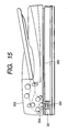
- Fig. 15 shows an example of a conventional image reading apparatus.
- the image reading apparatus shown in Fig. 15 is equipped with an original glass stand 300 for a reading system (hereinafter referred to as the book reading system) in which a stationary original placed thereon is read, a flow reading glass 301 for the flow reading system, and a reading sensor 302 consisting of a contact image sensor or the like which is an image reading means used for both reading systems.
- a reading system hereinafter referred to as the book reading system
- the reading sensor 302 consisting of a contact image sensor or the like which is an image reading means used for both reading systems.
- a platen roller 304 arranged above the flow reading glass 301 at a predetermined distance therefrom is rotated at a predetermined speed, whereby at the time of flow reading, the original is transported in a stable manner while restricting the amount by which the original is raised from the upper surface of the flow reading glass 301.
- the flow reading system using the platen roller 304 has a problem in that when there is a variation in the reading position, i.e., the stop position of the reading sensor 302, with respect to the platen roller, a variation in the brightness level of the read image is involved.
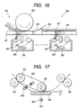
- Fig. 16 is a schematic view of a conventional image reading apparatus for explaining the cause of this phenomenon.
- the route of light from an illuminating means 305 in the case of the book reading system is designated by the reference sign 16A
- the route of light from the illuminating means 305 in the case of the flow reading system is designated by the reference sign 16B.
- the route of light applied from the illuminating means on one side and transmitted through the original is schematically indicated by double-dotted lines. In the example shown, the reading position for the flow reading system is deviated from the position directly below the center of the platen roller 304 to the upstream side with respect to the original transporting direction.
- the light transmitted through the original 306 is reflected in the direction of the reading sensor 302 by a white pressure plate 307 pressing the original 306 against the original glass stand 300, and illuminates the back surface of the original.
- a part of the light transmitted through the original 306 and reflected by the white platen roller 304 is reflected away from the reading sensor 302 due to the curvature of the platen roller 304.
- the quantity of light illuminating the back surface of the original 306 is reduced, resulting in a reduction in brightness when the reflected light from the original is read by an image sensor 309 through a lens 308.
- the quantity of light reflected in the direction of the reading sensor 302 decreases, resulting in a further reduction in the brightness of the image even when the same original is read.
- the portion of the surface of the flow reading glass 301 directly below the center of the platen roller 304 and the portion thereof on the downstream side in the original transporting direction are subject to adhesion of dirt.
- the reading position it is desirable for the reading position to be set somewhat upstream with respect to the position directly below the center of the platen roller 304.
- Fig. 17 shows another example of the construction of the portion of an original treatment apparatus using a platen roller which is in the vicinity of the reading position.
- transport roller pairs 402 and 403 situated on the upstream and downstream sides of the reading position 401 and adapted to transport the original at a predetermined speed, and a platen roller 405 situated substantially above the reading position and rotatable by a driving means (not shown).
- An exposure device 409 is provided below a platen glass plate 404 to perform image reading operation on an original transported at a uniform velocity between the platen roller 405 and the platen glass plate 404.
- the color of the platen roller 405 is white.
- the range in which reading by the exposure device 409 is possible must be a range in which the whiteness of the platen roller 405 is suited for reading.
- the exposure device is usually provided directly below the platen roller.
- the platen roller 405 is supported by an oscillation arm 406 so as to be capable of oscillating about a fulcrum shaft 407 (which, in this example, also serves as the shaft of one roller of the transport roller pair 402), and is pressurized downwards by an urging member 408. Due to this arrangement, when the original treatment apparatus is closed, the oscillation arm 406 abuts against the platen glass plate 404 and follows the reading position 401 through equalization.
- the outer diameter of the oscillation arm 406 is larger than the outer diameter of the platen roller 405, forming a gap X between the platen glass plate 404 and the platen roller 405.
- the conventional original treatment apparatus performing flow reading using a platen roller has the following problem:
- a white member facing the back surface of the original is provided in the portion of the image reading apparatus on the side opposed to the reading position.
- the original treatment apparatus using a platen roller is no exception, and is normally equipped with a white platen roller opposed to the reading position.
- the reading position has conventionally been adjusted to a position in which appropriate reading is possible through positional adjustment of the platen roller and the exposure device by using a jig, detection means, and the like.
- the US 2001/0033761 A1 discloses a sheet transport apparatus comprising supply means for successively supplying a plurality of sheets to a predetermined reading position, a platen glass plate provided in the predetermined reading position, a platen roller opposed to the platen glass plate, reading means opposed to the platen glass plate on a side opposite to the platen roller and adapted to perform exposure on a sheet on the platen glass plate to read an image on the sheet and a white guide member opposed to the platen glass plate upstream of the platen roller and downstream of the supply means in a transport direction, wherein a distance between the white guide member and the platen glass plate is longer than a distance between the platen glass plate and a surface of the platen roller.
- the US 4,812,917 discloses a sheet transport apparatus having a white guide member which is arranged upstream of the platen roller and urges the sheet towards the glass plate.
- the present invention has been made with a view toward solving the above problems. It is therefore an object of the present invention to provide an image reading apparatus capable of performing stable image reading involving little variation in image brightness even if.there is a variation in the reading position, and an image forming apparatus having such an image reading apparatus.
- Another object of the present invention is to enlarge the range in which the exposure device can reliably perform reading without involving an increase in the diameter of the white roller.
- the image reading apparatus includes: a transparent member for supporting the original in an image reading position; a reading means arranged in a position opposed to the transparent member and adapted to apply light from an illuminating means to the original on the transparent member to read an image of the original; and a rotatable rotary member opposed to the transparent member and disposed in a position on the side opposite to the illuminating means and the reading means. Also, a reflection member is provided in the vicinity of the rotary member, for reflecting light emitted from the illuminating means when reading the original while transporting it.
- a sheet transport apparatus includes: a supply means for successively supplying a plurality of sheets to a predetermined reading position; a platen glass plate provided in the predetermined reading position; a platen roller opposed to the platen glass plate; a reading means opposed to the platen glass plate on the side opposite to the platen roller and adapted to perform exposure on a sheet on the platen glass plate to read an image on the sheet; and a white guide member opposed to the platen glass plate on the upstream side of the platen roller in the transporting direction.
- the position in which the guide member is closest to the platen roller is on the platen roller side with respect to a plane which includes the point in the outer periphery of the platen roller that is closest to the platen glass plate and which is parallel to the platen glass plate, and the longitudinal length of the guide member is the same as or larger than the width of the range of the reading means which allows reading.
- Fig. 1 is a schematic diagram showing an original treatment apparatus and an image reading apparatus.
- the original treatment apparatus which is an example of a sheet transport apparatus, is one using the flow reading system.
- An original treatment apparatus 101 is provided on the top of an image reading apparatus 102 through the hinge portions 104. It transports the originals of an original stack on an original tray one by one to a reading position "e" of the image reading apparatus 102.
- the image reading apparatus 102 has a platen glass plate 10, a jump stand 11, and an exposure device 103 serving as the reading means.
- the exposure device 103 is fixed in the reading position "e", and performs flow reading on the image of an original being transported at a predetermined speed.
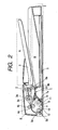
- Fig. 2 is a sectional view of the original treatment apparatus 101 of this comparative example.
- An original stacking portion A consists of a feed tray 1, on the surface of which originals are stacked.
- An original transporting portion B has a pickup roller 2, which draws the original stack on the feed tray 1 into a separating portion 3 (3a, 3b), and the uppermost sheet of the original stack is separated and transported to registration rollers 4 (4a, 4b) by a feed roller 3a and a frictional separation pad 3b.
- the registration rollers 4 (4a, 4b) are at rest when the leading edge of the original reaches them. They form a loop in the original through transport by the feed roller 3a to correct a skew feed of the original, and then transport the original to upstream transporting rollers 5 (5a, 5b) serving as a supply means.
- the upstream transporting rollers 5 (5a, 5b) pass the fed original through a gap between a platen roller 6 and the platen glass plate 10 and transports it toward downstream transporting rollers 7 (7a, 7b).
- the original which is gripped by the upstream transporting rollers 5 (5a, 5b) and the downstream transporting rollers 7 (7a, 7b), is transported on the reading position "e" at a predetermined speed, and exposure operation is performed by the exposure device 103 fixed in position below the reading position "e” on the platen glass plate 10, the image being read by the image reading apparatus 102.
- the original delivered from the downstream transporting rollers 7 (7a, 7b) is guided to delivery rollers 8 (8a, 8b) of an original delivery portion C. While exposure operation is being performed in the reading position "e", the delivery rollers 8 (8a, 8b) are separated from each other and perform no transporting operation in the original delivery portion C. After the trailing edge of the original has passed the reading position "e" to complete the reading, the delivery roller 8b moves upwards, and the original is nipped by the delivery roller 8a and the delivery roller 8b and delivered with face down onto a delivery tray 9 of a delivery stacking portion D.
- the original passing on the reading position "e” is gripped by the upstream transporting rollers 5 (5a, 5b) and the downstream transporting rollers 7 (7a, 7b), and transported between the platen glass plate 10 and the platen roller 6 at a predetermined speed.
- the exposure device 103 is fixed in position below the reading position "e" and records the image of the first side in the image reading apparatus.
- the delivery rollers 8 (8a, 8b) are reversed after the trailing edge of the original has passed the delivery sensor S1, and the original is switched back and transported to the registration rollers 4 (4a, 4b) of the original transporting portion B situated on the side opposite to the delivery direction.
- the registration rollers 4 (4a, 4b) transports the original to the reading position "e" on the platen glass plate 10 again, and as in the case of the first side, the original is transported at a predetermined speed by the upstream transport rollers 5 (5a, 5b) and the downstream transport rollers 7 (7a, 7b) to perform exposure operation on the second side before guiding the original to the original delivery portion C.
- the delivery rollers 8 (8a, 8b) are reversed to transport the original in the direction of the registration rollers 4 (4a, 4b) again, reversing the original to deliver it with face down onto the delivery tray 9 of the delivery stacking portion D.
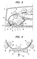
- Fig. 3 is a sectional view of the portion around the reading position of the image reading apparatus of this comparative example.
- the upstream transport rollers 5 (5a, 5b) are provided on the upstream side of the reading position "e"
- the downstream side transport rollers 7 (7a, 7b) are provided on the downstream side of the reading position "e”.
- the platen roller 6 is provided substantially above the reading position "e” and supported at its both ends by a pair of oscillation arms 13 so as to be rotatable by a driving means (not shown).
- the exposure device 103 is at rest at a position directly below the reading position in which reading is performed on the original transported.
- the oscillation arms 13 are attached to a shaft of one of the upstream transport rollers 5 (5a, 5b), and can be oscillated using the shaft as the oscillation fulcrum. Further, the oscillation arms 13 receive a downward force of an urging member 14.
- the oscillation arms 13 are equalized using the oscillation fulcrum as the oscillation center, with the platen roller 6 being substantially pressed.down.
- the oscillation arms 13 follow the platen glass plate 10 and are equalized while receiving a force directly substantially downward, with the platen roller 6 being situated substantially above the reading position "e".
- the outer diameter of the oscillation arms 13 is somewhat larger than that of the platen roller 6, and the oscillation arms 13 are in contact with the platen glass plate 10, thereby forming a minute gap between the platen roller 6 and the platen glass plate 10.
- the platen glass plate 10 is not damaged if the platen roller 6 rotates when there is no sheet. Further, it is advantageously possible to transport the original at an appropriate reading depth for the exposure device 103 without imparting load to the original.
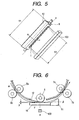
- Figs. 4 and 5 show the positional relationship between a white guide member and the platen roller in this comparative example.
- the guide member 12 is formed of a flexible white film consisting of a polyester film or the like, and has a flat configuration as shown in Fig. 5 .
- Fig. 4 shows how the guide member 12 is positioned with respect to the transporting direction.
- the guide member 12 is fixed to the distal end of a transport guide 20 formed of resin or metal.
- the distal end of the guide member 12 is left free.
- the platen roller 6 is designed so as to be equalized, so that in this state the original treatment apparatus 101 is closed with respect to the image reading apparatus 102, with the platen roller 6 following the platen glass plate 10 to be arranged at a predetermined position. In the following description, the platen roller 6 is in this positional relationship.
- the positional relationship between the guide member 12 and the platen roller 6 is as follows: The position of the guide member 12 in which it is closest to the platen roller 6 is on the platen roller side with respect to a plane ⁇ which is parallel to the platen glass plate and which contains the point in the outer periphery of the platen roller 6 which is closest to the platen glass plate 10.
- the distal end of the guide member 12 in the transporting direction is closest to the platen roller 6, the distal end being above the plane ⁇ .
- This arrangement is adopted for the purpose of preventing the distal end of the guide member 12 from coming into contact with the original during transportation of the original to thereby scrape the image surface of the original and of preventing load from being imparted to the original to thereby generate a blurred image.
- the width Y1 of the guide member 12 is the same as or larger than the width Y2 of the range "f" of the exposure device 103 allowing image reading, thereby preventing intrusion of external light and reflection of the shadow of a component during image reading.
- the guide member by using a flexible, thin white film for the guide member, it is possible to fill the gap up to the vicinity of the platen roller, thereby providing a further enhanced effect. Further, the guide member is out of contact of the original, so that it does not rub the image or impart load thereto.
- the guide member 12 is formed of a flexible white film consisting of a polyester film or the like, and has a flat configuration as shown in Fig. 5.
- Fig. 6 shows how the guide member 12 is situated with respect to the transporting direction. As shown in Fig. 6 , one end of the guide member 12 is glued to a transport guide surface on the inner side of the original treatment apparatus 101, and the other end thereof is in contact with the platen roller.
- the platen roller 6 is designed so as to be equalized at this time, so that in the condition shown, the original treatment apparatus 101 is closed with respect to the image reading apparatus 102, and the platen roller 6 follows the platen glass plate 10 to be arranged at a predetermined position. In the following description, the platen roller 6 is in this positional relationship.
- the positional relationship between the guide member 12 and the platen roller 6 is as follows: The position in which the guide member 12 abuts against the platen roller 6 is on the platen roller side with respect to a plane ⁇ which is parallel to the platen glass plate and which contains the point in the outer periphery of the platen roller 6 which is closest to the platen glass plate 10. That is, in this embodiment, the distal end of the guide member with respect to the transporting direction is closest to the platen roller 6, it is only necessary for the distal end to be above the plane ⁇ and in contact with the platen roller.
- This arrangement is adopted for the purpose of preventing the distal end of the guide member 12 from coming into contact with the original during transportation to thereby scrape the image surface of the original and of preventing the distal end from imparting load to the image surface during transportation of the original to thereby generate a blurred image.
- the guide member 12 is constantly urged in the direction ⁇ by its own resilient force, and even if its position is deviated as a result of a gluing error at the time of gluing, a variation in the platen roller 6, etc., it follows the platen roller 6, so that positional accuracy is easy to achieve, and the relationship between the platen glass plate 10 and the guide member 12 and the abutment relationship between the platen roller 6 and the distal end of the guide member 12 are secured, making it possible to maintain the above-described condition.
- the width Y1 of the guide member 12 is the same as or larger than the width Y2 of the range "f" of the exposure range 103 allowing image reading, whereby it is possible to prevent intrusion of external light and reflection of the shadow of a component during image reading.
- the guide member can cover the portion in the vicinity of the position directly below the platen roller without protruding into the transport path, whereby it is possible to further enlarge the range allowing reading as compared with that in the comparative example.
- the end position in which the white guide member is closest to the platen roller in the condition in which the original treatment apparatus is closed is on the platen roller side with respect to a plane which is parallel to the platen glass plate 10 and which includes the point in the platen roller outer periphery which is closest to the platen glass plate 10, and the longitudinal length of the guide member is the same as or larger than the length of the range of the exposure device allowing reading, whereby even if the reading position is deviated from the position directly below the platen roller 6, the quantity of light around the platen roller can be large, so that the influence of the shadow generated between the guide and the roller and the influence of the deficiency in light quantity due to roller bending are mitigated, making it possible to enlarge the range for the exposure device allowing reading.
- the end portion of the guide member does not protrude into the transport path, so that it does not come into contact with the original to scrape the same or generate a blurred image.
- the guide member is provided so as to be urged toward the platen roller by its own resilient force, so that even if there is a variation in the position of the platen roller, it always follows the platen roller, whereby positional accuracy can be maintained, and it does not protrude into the transport path or move away from the platen roller, making it possible to cover the portion up to the vicinity of the position directly below the roller.
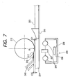
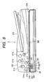
- Fig. 7 is a detailed sectional explanatory view of the flow reading portion of the image reading apparatus
- Fig. 8 is a general sectional explanatory view of the image reading apparatus
- Fig. 9 is a schematic explanatory view showing the brightness variation preventing effect of the reflection member
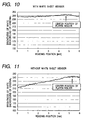
- Figs. 10 and 11 are graphs showing the relationship between the reading position in flow reading and the brightness of the white background of the original.
- the image reading apparatus E of this embodiment includes an image reading portion 201 and an ADF 202, which is an automatic original transport apparatus mounted on top of the image reading portion 201.
- the image reading portion 201 is capable of reading originals in both the book reading system and the flow reading system. That is, an original glass stand 203 is provided on the upper surface of the image reading portion 201, and, at one end of the original glass stand 203, there is provided a flow reading glass plate 204 as a transparent member for supporting an original to be read by flow reading.
- This reading means 205 includes a casing 209, which integrally contains an illuminating means 206 such as a xenon tube for applying light to the original on the glass plate, a SELFOC lens 207 for imaging the reflected light from the original, and a contact image sensor 208 arranged in the imaging position for the SELFOC lens 207.
- the casing 209 is caused to abut against the original glass stand 203 or the flow reading glass plate 204 through an abutment member (not shown) with high slidability, and the reading means 205 is spaced apart from the original surface by a predetermined distance.
- the ADF 202 is mounted to the upper portion of the image reading portion 201 so as to allow opening and closing by a hinge or the like, and there are provided rollers 211a through 211f adapted to supply originals to the image reading portion 201 and serving as original transport means for transporting one by one the originals in the form of sheets stacked on an original stacking portion 210, a platen roller 212 as a rotary member for preventing the original from rising from the flow reading glass plate 204 during flow reading, and an original delivery portion 213 for delivering the originals which have undergone image reading.
- the original placed on the original glass stand 203 is secured in position by a white pressure plate 214 mounted to the ADF 202, and the original is read while driving the reading means 205 at a predetermined speed in the sub scanning direction (the horizontal direction in Fig. 8 ).
- the ADF 202 functions as a pressure plate for fixing the original to the original glass stand 203.
- the original stacked on the original stacking portion 210 of the ADF 202 is fed by the feed roller 211a and transported at a predetermined speed to the position below the platen roller 212 by the transport rollers 211b, 211c, and 211d.
- the original is restricted in the amount by which it is raised from the upper surface of the flow reading glass plate 204 by the platen roller 212 rotating at a predetermined rotating speed, and the reading means 205 at rest at a predetermined reading position applies light from the illuminating means 206 to the original being transported between the platen roller 212 and the upper surface of the flow reading glass plate 204 to thereby perform image reading.
- the original having passed the platen roller 212 is guided to the transport rollers 211e and 211f by a jump stand 215 and delivered onto an original delivery portion 213.
- the ADF 202 of this embodiment is equipped with a white flexible sheet member 216 serving as a reflection member situated on the upstream side of the platen roller 212 in the original transporting direction.
- This white sheet member 216 is mounted to a guide member 240 for guiding the original to the platen roller 212 so as to be substantially parallel to the flow reading glass plate 204.
- the distance C2 between the white sheet member 216 and the flow reading glass plate 204 is larger than the distance C1 between the flow reading glass plate 204 and the surface of the platen roller 212 and smaller than the distance (C1 + R) between the flow reading glass plate 204 and the rotation center of the platen roller 212 (C1 ⁇ C2 ⁇ C1 + R).
- the end position 217 in which the sheet member 216 is close to the platen roller 212 is determined such that when seen from the reading position for the reading means 205 in the direction of the rotary member (the reading direction), that is, when seen from a position directly below the flow reading glass plate 204 in the direction of the platen roller 212 and the white sheet member 216 situated above, a part of the platen roller 212 is hidden substantially over the entire image reading range in the main scanning direction of the reading means 205 (the longitudinal direction of the platen roller 212). Further, the reading position in the case of the flow reading system is set to a position that allows reading of the surface of the platen roller 212 when no original is being transported.
- Fig. 9 schematically shows the route of light applied from the illuminating means 206 on one side (the left-hand side in this embodiment) and transmitted through the original.
- the reading position for flow reading is set to a position deviated from the position directly below the rotation center of the platen roller 212 to the upstream side in the original transporting direction.
- the light transmitted through the original 218 is reflected in the direction of the reading means 205 by the white sheet member 216. It can be seen that the quantity of light applied to the back surface of the original 218 is larger than that in the case of the conventional example designated by the reference sign 16B in Fig. 16 . Due to this arrangement, the reduction in brightness when the reading position is deviated from the position directly below the center of the platen roller 212 can be mitigated.
- Figs. 10 and 11 show the results of measurement of the relationship between the reading position in flow reading and the brightness of the white background of the original (0 to 255 level).
- Fig. 10 shows the measurement result of this embodiment, in which the white sheet member 216 is mounted
- Fig. 11 shows the measurement result of the case in which no white sheet member 216 is mounted.
- the white sheet member 216 does not come into contact with the original 218 regulated by the platen roller 212, and reflects the light from the illuminating means 206 without hindering the transport of the original 218 or rubbing the original surface to generate dust.
- the white sheet member 216 when seen upwardly (in the direction of the platen roller 212) from the reading position for the reading means 205, the white sheet member 216 hides a part of the platen roller 212 over the entire reading range, so that the light applied from the reading position by the illuminating means 206 and transmitted through the original is reliably reflected by the white sheet member 216 or the platen roller 212. Thus, no deterioration in brightness occurs.
- the white sheet member 216 is mounted so as to be parallel to the flow reading glass plate 204, the light transmitted through the original is reflected in the same manner as in the case in which it is reflected by the white pressure plate 214 in book reading, and there is no substantial difference in brightness between book reading and flow reading.
- the reading position for flow reading is set to a position between the position directly below the rotation center of the platen roller 212 and the distal end 217 of the white sheet member 216. That is, when no original is being transported, it is set to a position in which the surface of the platen roller 212 is read, so that it is possible to distinguish between the dust on the flow reading glass plate 204 and the dust on the platen roller 212 when performing detection, whereby it is possible to perform high quality image reading involving no streaked image. Further, by setting the reading position on the upstream side of the rotation center of the platen roller 212 with respect to the original transporting direction, it is possible to make the platen roller 212 less subject to adhesion of dust.
- Fig. 12 is a detailed sectional explanatory view of the flow reading portion
- Fig. 13 is a schematic explanatory view illustrating the brightness variation preventing effect.
- This embodiment differs from the third embodiment in that while in the third embodiment the white sheet member 216 is mounted so as to be parallel to the flow reading glass plate 204, the white sheet member 216 of this embodiment is arranged such that the distance between the white sheet member 216 and the flow reading glass plate 204 increases as the white sheet member 216 approaches the platen roller 212.
- this embodiment is of the same construction as the comparative example.
- the white sheet member 216 is mounted obliquely so that the distance between the white sheet member 216 and the flow reading glass plate 204 may be such that the distance C4 at the downstream end in the original transporting direction is larger than the distance C3 at the upstream end. Then, the minimum distance C3 between the white sheet member 216 and the flow reading glass plate 204 is larger than the distance C1 between the flow reading glass plate 204 and the surface of the platen roller 212, and the maximum distance C4 between the white sheet member 216 and the flow reading glass plate 204 is smaller than the distance (C1 + R) between the flow reading glass plate 204 and the center of the platen roller 212.
- Fig. 13 schematically shows the route of light emitted from the illuminating means 206 on one side and transmitted through the original.
- the light transmitted through the original 218 is reflected in the direction of the reading means 205 by the white sheet member 216.
- the white sheet member of this embodiment is inclined with respect to the flow reading glass plate 204, so that it has the effect of condensing the light transmitted through the original 218 in the direction of the reading means 205.
- more light is thrown from the back side of the original 218. Due to this arrangement, the reduction in brightness when the reading position is deviated from the rotation center of the platen roller 212 is further mitigated, and even if there is a variation in the reading position, it is possible to perform a stable image reading involving little variation in brightness.
- the white sheet member 216 is formed in a concave configuration with respect to the illuminating means 206, the light from the illuminating means 206 is condensed at the reading means 205 more effectively.
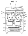
- Fig. 14 is a general schematic explanatory view of an image forming apparatus.
- the construction of the image reading apparatus E is the same as that described with reference to the third embodiment.
- the image recording apparatus F performs image recording on the basis of image data read by the image reading apparatus E or image data read by some other image reading apparatus and transmitted.
- the recording media set in a selected one of sheet accommodating portions 219a, 219b, 219c, and 219d, and a tray 219e is transported to an image forming means for image formation by driving a selected one of feeding portions 220a, 220b, 220c, 220d, and 220e and a transport roller 231.
- the image forming means comprises a photosensitive drum 221, a charger 222 for uniformly charging the surface of the photosensitive drum 221, an exposure means 223 for selectively performing exposure on the surface of the photosensitive drum 221 charged by the charger 222 according to image information, a developing device 224 for developing an electrostatic latent image formed on the photosensitive drum 221 through exposure by the exposure means 223 and forming a toner image to be transferred to the recording medium transported, a transfer charger 225 for transferring the developed toner image on the surface of the photosensitive drum 221 to the recording medium, a separation charger 226 for separating the recording medium to which the toner image has been transferred from the photosensitive drum 221, and a cleaner 227 for removing residual toner on the photosensitive drum 221 after the transfer of the toner image.
- the image forming means forms an image on the recording medium by electrophotography.
- the recording medium on which an image has been formed is transported to a fixing device 229 by a transport portion 228, and is delivered onto a delivery tray 230 after the toner image has been fixed by heating.
- the variation in brightness during flow reading of the original is effectively prevented, as in the above-described embodiments, making it possible to perform a stable image reading and to realize a high-quality and highspeed image formation based thereon.
- the reading position is set to be on the upstream side of the position directly below the rotation center of the platen roller 212 in the original transporting direction, and the white sheet member 216 is provided on the upstream side. It is to be noted, however, that the adhesion of dust to the flow reading glass plate 204 is also varied by the configuration of the original transport path, etc.
- the reading position it is also possible to set the reading position to be on the downstream side of the position directly below the rotation center of the platen roller 212 in the original transporting direction, and to accordingly provide the white sheet member 216 which is reflection member on the downstream side, or to set the flow reading position to be on each side of the position directly below the rotation center of the platen roller 212, providing the white sheet member 216 on each of the upstream and the downstream sides in the original transporting direction.
- the reflection member may be of any other type as long as it is capable of effectively reflecting the light from the illuminating means 206.
- a supply means for successively supplying a plurality of sheets to a predetermined reading position, a platen glass plate provided in the predetermined reading position, a platen roller provided so as to be opposed to the platen glass plate, a reading means provided so as to be opposed to the platen glass plate on the side opposite to the platen roller and adapted to perform exposure on the sheet on the platen glass plate to read the image on the sheet, and a white guide member provided so as to be opposed to the platen glass plate on the upstream side of the platen roller in the transporting direction, wherein the position in which the guide member is closest to the platen roller is on the platen roller side with respect to a plane which is parallel to the platen glass plate and which includes the point in the outer periphery of the platen roller which is closest to the platen glass plate, and wherein the longitudinal length of the guide member is the same as or larger than the width of the range of the reading means which allows reading, whereby it is possible to en
- a reflection member for reflecting light from the illuminating means when reading the original while transporting the original, so that the light transmitted through the original is reflected in the direction of the image reading means to illuminate the original from the back side.
Claims (14)
- Blattbeförderungsgerät mit:einer Zuführeinrichtung (5a, 5b; 211d) zum aufeinanderfolgenden Zuführen einer Vielzahl von Blättern zu einer vorbestimmten Leseposition;einer Andruckglasplatte (10; 204), die bei der vorbestimmten Leseposition vorgesehen ist;einer Andruckwalze (6; 212), die der Andruckglasplatte (10; 204) gegenüberliegt;einer Leseeinrichtung (205), die der Andruckglasplatte (10; 204) auf einer zu der Andruckwalze (6; 212) gegenüberliegenden Seite gegenüberliegt und angepasst ist, um eine Aufnahme von einem Blatt auf der Andruckglasplatte (10; 204) durchzuführen, um ein Bild auf dem Blatt zu lesen; undeinem weißen Führungsbauteil (12; 216), das in einer Beförderungsrichtung stromaufwärts der Andruckwalze (6; 212) und stromabwärts der Zuführeinrichtung (5a, 5b; 211d) der Andruckglasplatte (10; 204) gegenüberliegt, wobeiein Abstand zwischen dem weißen Führungsbauteil (12; 216) und der Andruckglasplatte (10; 204) größer als ein Abstand zwischen der Andruckglasplatte (10; 204) und einer Oberfläche der Andruckwalze (6; 212) ist,dadurch gekennzeichnet, dassein distales Ende des weißen Führungsbauteils (12; 216) an einer Stelle mit der Andruckwalze (6; 212) in Kontakt ist, die sich in Bezug auf die Ebene, die den am nächsten zu der Andruckglasplatte (10; 204) befindlichen Punkt in dem Außenumfang der Andruckwalze (6; 212) aufweist und die parallel zu der Andruckglasplatte (10; 204) ist, auf der Seite der Andruckwalze befindet.
- Blattbeförderungsgerät gemäß Anspruch 1, wobei das weiße Führungsbauteil (12; 216) ein weißes elastisches Bauteil aufweist, das eine Flexibilität besitzt.
- Bildlesegerät mit:einem Originalhandhabungsgerät (101; 202) zum Befördern eines Blatts; undeiner Blattbeförderungseinrichtung zum Transportieren des Blatts während eines Bildlesens zum Lesen eines Bildes auf dem Blatt, wobei die Blattbeförderungseinrichtung ein Blattbeförderungsgerät gemäß einem der Ansprüche 1 bis 2 ist.
- Bildlesegerät gemäß Anspruch 3, wobei ein Abstand zwischen dem weißen Führungsbauteil (12; 216) und der Andruckglasplatte (10; 204) kleiner als ein Abstand zwischen der Andruckglasplatte (10; 204) und einer Drehmitte der Andruckwalze (6; 212) ist.
- Bildlesegerät gemäß Anspruch 3, wobei ein distales Ende des weißen Führungsbauteils (12; 216), das der Andruckwalze (6; 212) am nächsten ist, derart platziert ist, dass das weiße Führungsbauteil (12; 216) einen Teil der Andruckwalze (6; 212) in einem im Wesentlichen gesamten Lesebereich für die Leseeinrichtung (205) verdeckt, wenn es von der Leseposition für die Leseeinrichtung (205) aus in Richtung der Andruckwalze (6; 212) betrachtet wird.
- Bildlesegerät gemäß Anspruch 3, wobei das weiße Führungsbauteil (12; 216) parallel zu der Andruckglasplatte (10; 204) angeordnet ist.
- Bildlesegerät gemäß Anspruch 3, wobei das weiße Führungsbauteil (12; 216) derart angeordnet ist, dass der Abstand zwischen dem weißen Führungsbauteil (12; 216) und der Andruckglasplatte (10; 204) zunimmt, wenn sich das weiße Führungsbauteil (12; 216) der Andruckwalze (6; 212) nähert.
- Bildlesegerät gemäß Anspruch 3, wobei die Leseposition zum Lesen des Originals während eines Transportierens des Originals auf eine Position festgelegt ist, bei der eine Fläche der Andruckwalze (6; 212) gelesen wird, wenn kein Original transportiert wird.
- Bildlesegerät gemäß Anspruch 8, wobei die Leseposition zum Lesen des Originals während eines Transportierens des Originals in einer Originalbeförderungsrichtung stromaufwärts einer Drehmitte der Andruckwalze (6; 212) ist.
- Bilderzeugungsgerät, das mit einer Originalbeförderungseinrichtung zum Transportieren eines Originals in der Form eines Blatts versehen ist und Informationen, die durch ein Bildlesegerät gelesen werden, welches das Original lesen kann, während es das Original transportiert, auf ein Aufzeichnungsmedium aufzeichnen kann, wobei das Bilderzeugungsgerät aufweist:ein Bildlesegerät gemäß einem der Ansprüche 4 bis 9; undeine Bilderzeugungseinrichtung zum Aufzeichnen eines Bildes auf das Aufzeichnungsmedium.
- Bildlesegerät mit:dem Blattbeförderungsgerät gemäß Anspruch 2.
- Bildlesegerät gemäß Anspruch 11, wobei das weiße Führungsbauteil (12; 216) an einem distalen Ende einer Transportführung (20) zum Führen des Originals zu der Andruckglasplatte (10; 204) montiert ist.
- Bildlesegerät gemäß Anspruch 11, wobei die Leseeinrichtung (205) ein Bild eines Abschnitts des sich bewegenden Originals bei einer Position liest, die stromaufwärtig einer Position postioniert ist, bei der ein Abstand zwischen einer Außenumfangsfläche der Andruckwalze (6; 212) und einer Andruckglasplatte (10; 204) minimal ist.
- Bildlesegerät gemäß Anspruch 11, das ferner eine Bilderzeugungseinrichtung zum Ausbilden eines Bildes auf einem Aufzeichnungsmedium auf der Basis von Bildinformationen aufweist, die durch die Leseeinrichtung (205) gelesen werden.
Applications Claiming Priority (5)
| Application Number | Priority Date | Filing Date | Title |
|---|---|---|---|
| JP2001388845A JP2003189059A (ja) | 2001-12-21 | 2001-12-21 | シート搬送装置及び画像読取装置 |
| JP2001388845 | 2001-12-21 | ||
| JP2002021129 | 2002-01-30 | ||
| JP2002021129A JP4208470B2 (ja) | 2002-01-30 | 2002-01-30 | 画像読み取り装置及び画像形成装置 |
| PCT/JP2002/013217 WO2003055199A1 (en) | 2001-12-21 | 2002-12-18 | Sheet transport apparatus and image reading apparatus |
Publications (3)
| Publication Number | Publication Date |
|---|---|
| EP1457036A1 EP1457036A1 (de) | 2004-09-15 |
| EP1457036A4 EP1457036A4 (de) | 2005-07-20 |
| EP1457036B1 true EP1457036B1 (de) | 2009-09-09 |
Family
ID=26625201
Family Applications (1)
| Application Number | Title | Priority Date | Filing Date |
|---|---|---|---|
| EP02790797A Expired - Lifetime EP1457036B1 (de) | 2001-12-21 | 2002-12-18 | Blatttransportvorrichtung und bildlesevorrichtung |
Country Status (7)
| Country | Link |
|---|---|
| US (1) | US7385735B2 (de) |
| EP (1) | EP1457036B1 (de) |
| KR (1) | KR100732594B1 (de) |
| CN (1) | CN1323539C (de) |
| DE (1) | DE60233676D1 (de) |
| TW (1) | TWI231138B (de) |
| WO (1) | WO2003055199A1 (de) |
Families Citing this family (22)
| Publication number | Priority date | Publication date | Assignee | Title |
|---|---|---|---|---|
| JP3923027B2 (ja) * | 2003-04-28 | 2007-05-30 | 京セラミタ株式会社 | 画像読み取り部に用いられる原稿搬送ガイド |
| US7428084B2 (en) * | 2004-01-23 | 2008-09-23 | Eastman Kodak Company | Scanner with removable image guides |
| US8098411B2 (en) * | 2004-08-31 | 2012-01-17 | Brother Kogyo Kabushiki Kaisha | Image reading apparatus |
| JP4498149B2 (ja) * | 2005-01-17 | 2010-07-07 | キヤノン株式会社 | 画像読み取り装置 |
| KR100577689B1 (ko) | 2005-01-19 | 2006-05-10 | 삼성전자주식회사 | 화상독취장치, 그 화상독취장치의 가이드필름 오염 체크방법 ,및 그 화상독취장치를 이용한 화상형성장치. |
| JP4075906B2 (ja) * | 2005-05-10 | 2008-04-16 | コニカミノルタビジネステクノロジーズ株式会社 | 画像読取装置および画像形成装置 |
| US8149473B2 (en) * | 2005-12-27 | 2012-04-03 | Canon Kabushiki Kaisha | Image reading apparatus |
| JP4533311B2 (ja) * | 2005-12-27 | 2010-09-01 | キヤノン株式会社 | 画像読取装置および画像形成装置 |
| JP2009177310A (ja) * | 2008-01-22 | 2009-08-06 | Kyocera Mita Corp | 画像読取装置及び画像形成装置 |
| TWI386028B (zh) * | 2008-04-21 | 2013-02-11 | Avision Inc | 具軟性壓制元件之掃描裝置 |
| TWI395461B (zh) * | 2008-11-11 | 2013-05-01 | Avision Inc | 具有非直線型饋紙通道之掃描設備 |
| US8854706B2 (en) * | 2009-07-07 | 2014-10-07 | Kabushiki Kaisha Toshiba | Auto document feeding device |
| USRE46846E1 (en) * | 2009-08-31 | 2018-05-15 | Sharp Kabushiki Kaisha | Image forming apparatus provided with post-processing device |
| JP4815517B2 (ja) * | 2009-08-31 | 2011-11-16 | シャープ株式会社 | 画像形成装置 |
| US8355160B2 (en) * | 2010-07-26 | 2013-01-15 | Hewlett-Packard Development Company, L.P. | Detection of roller eccentricity in a scanner |
| CN103797778A (zh) * | 2011-09-21 | 2014-05-14 | 惠普发展公司,有限责任合伙企业 | 介质提升装置 |
| JP6324212B2 (ja) * | 2014-05-27 | 2018-05-16 | サトーホールディングス株式会社 | 弾性体ローラー |
| JP6700968B2 (ja) * | 2016-05-20 | 2020-05-27 | キヤノン株式会社 | 画像読取装置及び画像形成装置 |
| JP6658647B2 (ja) * | 2017-03-28 | 2020-03-04 | 京セラドキュメントソリューションズ株式会社 | 給紙装置及び画像形成装置 |
| CN113572910A (zh) | 2017-06-09 | 2021-10-29 | 虹光精密工业股份有限公司 | 具有倾斜背景片的感光设备及其感光方法 |
| CN207150695U (zh) * | 2017-06-09 | 2018-03-27 | 虹光精密工业股份有限公司 | 具有倾斜背景片的感光设备 |
| JP7310447B2 (ja) * | 2019-08-29 | 2023-07-19 | セイコーエプソン株式会社 | 読取装置、汚れ表示方法および表示装置 |
Family Cites Families (19)
| Publication number | Priority date | Publication date | Assignee | Title |
|---|---|---|---|---|
| US4812917A (en) * | 1986-03-20 | 1989-03-14 | Ricoh Company, Ltd. | Device for reducing document in size having two facing non-parallel mirrors |
| JP2656123B2 (ja) | 1989-10-20 | 1997-09-24 | キヤノン株式会社 | 読取装置 |
| US5661571A (en) * | 1990-10-11 | 1997-08-26 | Canon Kabushiki Kaisha | Image reading device |
| JP3073045B2 (ja) | 1991-04-26 | 2000-08-07 | キヤノン株式会社 | 原稿画像読取装置 |
| JPH0582168A (ja) | 1991-09-25 | 1993-04-02 | Sanyo Electric Co Ltd | 非水系電解液電池 |
| JPH05103165A (ja) * | 1991-10-03 | 1993-04-23 | Canon Inc | 原稿読取装置 |
| JPH0582168U (ja) * | 1992-04-03 | 1993-11-05 | 三洋電機株式会社 | 原稿読取装置 |
| US5579129A (en) | 1993-12-17 | 1996-11-26 | Canon Kabushiki Kaisha | Original reading apparatus and information processing apparatus with original reading apparatus |
| US6166394A (en) | 1998-12-07 | 2000-12-26 | Xerox Corporation | Dual background document scanner to eliminate hole printouts |
| JP2001048374A (ja) * | 1999-08-13 | 2001-02-20 | Ricoh Co Ltd | 原稿読取装置 |
| US6618575B2 (en) | 2000-04-20 | 2003-09-09 | Nisca Corporation | Automatic document feeder with a conveying roller and an image reader |
| CN1203657C (zh) | 2001-08-07 | 2005-05-25 | 佳能株式会社 | 图像处理方法和装置 |
| JP2003143377A (ja) | 2001-10-31 | 2003-05-16 | Canon Inc | 画像読み取り装置 |
| US7327497B2 (en) * | 2002-05-14 | 2008-02-05 | Canon Kabushiki Kaisha | Image reading apparatus, control method therefor, and program |
| JP4065501B2 (ja) * | 2002-06-13 | 2008-03-26 | キヤノン株式会社 | 画像読取装置 |
| JP2004173165A (ja) * | 2002-11-22 | 2004-06-17 | Canon Inc | 画像読取装置 |
| US7450279B2 (en) * | 2003-02-19 | 2008-11-11 | Canon Kabushiki Kaisha | Image reading apparatus |
| US7302181B2 (en) * | 2003-02-25 | 2007-11-27 | Avago Technologies Ecbu Ip (Singapore) Pte. Ltd. | Single lens multiple light source device |
| JP4332443B2 (ja) * | 2003-03-07 | 2009-09-16 | キヤノン株式会社 | 画像読取装置及び画像形成装置 |
-
2002
- 2002-12-18 DE DE60233676T patent/DE60233676D1/de not_active Expired - Lifetime
- 2002-12-18 EP EP02790797A patent/EP1457036B1/de not_active Expired - Lifetime
- 2002-12-18 WO PCT/JP2002/013217 patent/WO2003055199A1/en active Application Filing
- 2002-12-18 KR KR1020047009742A patent/KR100732594B1/ko active IP Right Grant
- 2002-12-18 US US10/494,724 patent/US7385735B2/en not_active Expired - Fee Related
- 2002-12-18 CN CNB028252071A patent/CN1323539C/zh not_active Expired - Fee Related
- 2002-12-19 TW TW091136712A patent/TWI231138B/zh not_active IP Right Cessation
Also Published As
| Publication number | Publication date |
|---|---|
| TW200301650A (en) | 2003-07-01 |
| EP1457036A4 (de) | 2005-07-20 |
| CN1323539C (zh) | 2007-06-27 |
| TWI231138B (en) | 2005-04-11 |
| US20040246540A1 (en) | 2004-12-09 |
| KR20040077680A (ko) | 2004-09-06 |
| CN1605188A (zh) | 2005-04-06 |
| US7385735B2 (en) | 2008-06-10 |
| DE60233676D1 (de) | 2009-10-22 |
| WO2003055199A1 (en) | 2003-07-03 |
| KR100732594B1 (ko) | 2007-06-27 |
| EP1457036A1 (de) | 2004-09-15 |
Similar Documents
| Publication | Publication Date | Title |
|---|---|---|
| EP1457036B1 (de) | Blatttransportvorrichtung und bildlesevorrichtung | |
| JP3943942B2 (ja) | 原稿搬送装置及び画像読取装置及び画像形成装置 | |
| JP4176100B2 (ja) | 画像形成装置 | |
| JP2000284641A (ja) | 画像形成装置 | |
| JP3347858B2 (ja) | 原稿搬送装置およびそれを搭載した原稿読取装置 | |
| JP3571288B2 (ja) | 画像読取手段を具備する自動原稿送り装置及び画像読取装置 | |
| JP4585698B2 (ja) | 画像形成装置 | |
| JP2001253613A (ja) | 用紙搬送機構 | |
| JP2002335372A (ja) | 画像読取装置及び画像形成装置 | |
| JP7130187B2 (ja) | シート搬送装置、画像読取装置及び画像形成装置 | |
| JP4208470B2 (ja) | 画像読み取り装置及び画像形成装置 | |
| JP2010060911A (ja) | 開閉装置及びこれを備えた画像形成装置 | |
| JP2001194835A (ja) | 自動原稿搬送装置、画像読取装置、および画像形成装置 | |
| JP3625398B2 (ja) | 原稿搬送装置、原稿搬送装置を備えた画像読取装置及び画像読取装置を備えた画像形成装置 | |
| JPH11136436A (ja) | 画像読取装置 | |
| JP3964277B2 (ja) | 画像読取装置 | |
| JP2008112118A (ja) | 記録媒体搬送装置および画像形成装置 | |
| JP2009105830A (ja) | 画像読取装置および画像形成装置 | |
| JP2003189059A (ja) | シート搬送装置及び画像読取装置 | |
| JP2013011684A (ja) | 画像形成装置及びそのオフセンター補正方法 | |
| JPH09188453A (ja) | 原稿送り装置及び画像形成装置 | |
| JP2010278956A (ja) | 原稿読取送装置及び画像形成装置 | |
| JPH1028205A (ja) | 画像読取装置及び画像形成装置 | |
| JP2000226136A (ja) | シート搬送装置及び画像形成装置 | |
| JP2004072315A (ja) | 画像形成装置 |
Legal Events
| Date | Code | Title | Description |
|---|---|---|---|
| PUAI | Public reference made under article 153(3) epc to a published international application that has entered the european phase |
Free format text: ORIGINAL CODE: 0009012 |
|
| 17P | Request for examination filed |
Effective date: 20040510 |
|
| AK | Designated contracting states |
Kind code of ref document: A1 Designated state(s): AT BE BG CH CY CZ DE DK EE ES FI FR GB GR IE IT LI LU MC NL PT SE SI SK TR |
|
| A4 | Supplementary search report drawn up and despatched |
Effective date: 20050608 |
|
| 17Q | First examination report despatched |
Effective date: 20060202 |
|
| 17Q | First examination report despatched |
Effective date: 20060202 |
|
| GRAP | Despatch of communication of intention to grant a patent |
Free format text: ORIGINAL CODE: EPIDOSNIGR1 |
|
| GRAS | Grant fee paid |
Free format text: ORIGINAL CODE: EPIDOSNIGR3 |
|
| GRAA | (expected) grant |
Free format text: ORIGINAL CODE: 0009210 |
|
| AK | Designated contracting states |
Kind code of ref document: B1 Designated state(s): DE FR GB IT |
|
| REG | Reference to a national code |
Ref country code: GB Ref legal event code: FG4D |
|
| REF | Corresponds to: |
Ref document number: 60233676 Country of ref document: DE Date of ref document: 20091022 Kind code of ref document: P |
|
| PLBE | No opposition filed within time limit |
Free format text: ORIGINAL CODE: 0009261 |
|
| STAA | Information on the status of an ep patent application or granted ep patent |
Free format text: STATUS: NO OPPOSITION FILED WITHIN TIME LIMIT |
|
| 26N | No opposition filed |
Effective date: 20100610 |
|
| PGFP | Annual fee paid to national office [announced via postgrant information from national office to epo] |
Ref country code: IT Payment date: 20141204 Year of fee payment: 13 |
|
| REG | Reference to a national code |
Ref country code: FR Ref legal event code: PLFP Year of fee payment: 14 |
|
| REG | Reference to a national code |
Ref country code: FR Ref legal event code: PLFP Year of fee payment: 15 |
|
| PG25 | Lapsed in a contracting state [announced via postgrant information from national office to epo] |
Ref country code: IT Free format text: LAPSE BECAUSE OF NON-PAYMENT OF DUE FEES Effective date: 20151218 |
|
| REG | Reference to a national code |
Ref country code: FR Ref legal event code: PLFP Year of fee payment: 16 |
|
| PGFP | Annual fee paid to national office [announced via postgrant information from national office to epo] |
Ref country code: FR Payment date: 20171229 Year of fee payment: 16 |
|
| PGFP | Annual fee paid to national office [announced via postgrant information from national office to epo] |
Ref country code: GB Payment date: 20171228 Year of fee payment: 16 |
|
| PGFP | Annual fee paid to national office [announced via postgrant information from national office to epo] |
Ref country code: DE Payment date: 20180228 Year of fee payment: 16 |
|
| REG | Reference to a national code |
Ref country code: DE Ref legal event code: R119 Ref document number: 60233676 Country of ref document: DE |
|
| GBPC | Gb: european patent ceased through non-payment of renewal fee |
Effective date: 20181218 |
|
| PG25 | Lapsed in a contracting state [announced via postgrant information from national office to epo] |
Ref country code: FR Free format text: LAPSE BECAUSE OF NON-PAYMENT OF DUE FEES Effective date: 20181231 Ref country code: DE Free format text: LAPSE BECAUSE OF NON-PAYMENT OF DUE FEES Effective date: 20190702 |
|
| PG25 | Lapsed in a contracting state [announced via postgrant information from national office to epo] |
Ref country code: GB Free format text: LAPSE BECAUSE OF NON-PAYMENT OF DUE FEES Effective date: 20181218 |