EP1407357B1 - Bride de fixation servant a l'assemblage d'elements de construction en bois - Google Patents
Bride de fixation servant a l'assemblage d'elements de construction en bois Download PDFInfo
- Publication number
- EP1407357B1 EP1407357B1 EP02754861A EP02754861A EP1407357B1 EP 1407357 B1 EP1407357 B1 EP 1407357B1 EP 02754861 A EP02754861 A EP 02754861A EP 02754861 A EP02754861 A EP 02754861A EP 1407357 B1 EP1407357 B1 EP 1407357B1
- Authority
- EP
- European Patent Office
- Prior art keywords
- web
- fixing bracket
- bracket according
- angle
- beads
- Prior art date
- Legal status (The legal status is an assumption and is not a legal conclusion. Google has not performed a legal analysis and makes no representation as to the accuracy of the status listed.)
- Expired - Lifetime
Links
- 238000005304 joining Methods 0.000 title claims abstract description 9
- 239000000758 substrate Substances 0.000 claims abstract description 14
- 239000011324 bead Substances 0.000 claims description 41
- 239000002184 metal Substances 0.000 claims description 18
- 210000002105 tongue Anatomy 0.000 claims description 16
- 239000000463 material Substances 0.000 claims description 14
- 238000005452 bending Methods 0.000 claims description 8
- 238000000034 method Methods 0.000 claims description 5
- 238000003466 welding Methods 0.000 claims description 2
- 210000003323 beak Anatomy 0.000 claims 1
- 210000002414 leg Anatomy 0.000 description 17
- 210000002683 foot Anatomy 0.000 description 16
- 239000002023 wood Substances 0.000 description 15
- 125000006850 spacer group Chemical group 0.000 description 8
- 238000009423 ventilation Methods 0.000 description 7
- 238000005520 cutting process Methods 0.000 description 5
- 238000013461 design Methods 0.000 description 5
- 210000000078 claw Anatomy 0.000 description 4
- 238000003780 insertion Methods 0.000 description 4
- 230000037431 insertion Effects 0.000 description 4
- 239000011121 hardwood Substances 0.000 description 3
- 238000004519 manufacturing process Methods 0.000 description 3
- 238000003825 pressing Methods 0.000 description 3
- 230000000630 rising effect Effects 0.000 description 3
- 230000008961 swelling Effects 0.000 description 3
- 238000010276 construction Methods 0.000 description 2
- 230000006378 damage Effects 0.000 description 2
- 230000000694 effects Effects 0.000 description 2
- 238000005516 engineering process Methods 0.000 description 2
- 238000007373 indentation Methods 0.000 description 2
- 230000035515 penetration Effects 0.000 description 2
- 230000000284 resting effect Effects 0.000 description 2
- 238000010008 shearing Methods 0.000 description 2
- 238000012546 transfer Methods 0.000 description 2
- 241000293849 Cordylanthus Species 0.000 description 1
- 208000027418 Wounds and injury Diseases 0.000 description 1
- 210000003423 ankle Anatomy 0.000 description 1
- 230000015572 biosynthetic process Effects 0.000 description 1
- 238000005253 cladding Methods 0.000 description 1
- 230000008094 contradictory effect Effects 0.000 description 1
- 239000007799 cork Substances 0.000 description 1
- 238000005336 cracking Methods 0.000 description 1
- 230000001419 dependent effect Effects 0.000 description 1
- 238000002845 discoloration Methods 0.000 description 1
- 238000006073 displacement reaction Methods 0.000 description 1
- 238000004049 embossing Methods 0.000 description 1
- 210000003414 extremity Anatomy 0.000 description 1
- 238000005562 fading Methods 0.000 description 1
- 239000000835 fiber Substances 0.000 description 1
- 238000005755 formation reaction Methods 0.000 description 1
- 208000014674 injury Diseases 0.000 description 1
- 238000009434 installation Methods 0.000 description 1
- 238000013508 migration Methods 0.000 description 1
- 230000005012 migration Effects 0.000 description 1
- 238000009527 percussion Methods 0.000 description 1
- 230000008092 positive effect Effects 0.000 description 1
- 230000002787 reinforcement Effects 0.000 description 1
- 238000000926 separation method Methods 0.000 description 1
- 238000012549 training Methods 0.000 description 1
- 210000000689 upper leg Anatomy 0.000 description 1
Images


Classifications
-
- F—MECHANICAL ENGINEERING; LIGHTING; HEATING; WEAPONS; BLASTING
- F16—ENGINEERING ELEMENTS AND UNITS; GENERAL MEASURES FOR PRODUCING AND MAINTAINING EFFECTIVE FUNCTIONING OF MACHINES OR INSTALLATIONS; THERMAL INSULATION IN GENERAL
- F16B—DEVICES FOR FASTENING OR SECURING CONSTRUCTIONAL ELEMENTS OR MACHINE PARTS TOGETHER, e.g. NAILS, BOLTS, CIRCLIPS, CLAMPS, CLIPS OR WEDGES; JOINTS OR JOINTING
- F16B15/00—Nails; Staples
- F16B15/0023—Nail plates
- F16B15/003—Nail plates with teeth cut out from the material of the plate
- F16B15/0046—Nail plates with teeth cut out from the material of the plate from the body of the plate
-
- E—FIXED CONSTRUCTIONS
- E04—BUILDING
- E04F—FINISHING WORK ON BUILDINGS, e.g. STAIRS, FLOORS
- E04F13/00—Coverings or linings, e.g. for walls or ceilings
- E04F13/07—Coverings or linings, e.g. for walls or ceilings composed of covering or lining elements; Sub-structures therefor; Fastening means therefor
- E04F13/08—Coverings or linings, e.g. for walls or ceilings composed of covering or lining elements; Sub-structures therefor; Fastening means therefor composed of a plurality of similar covering or lining elements
- E04F13/0801—Separate fastening elements
- E04F13/0832—Separate fastening elements without load-supporting elongated furring elements between wall and covering elements
- E04F13/0833—Separate fastening elements without load-supporting elongated furring elements between wall and covering elements not adjustable
- E04F13/0841—Separate fastening elements without load-supporting elongated furring elements between wall and covering elements not adjustable the fastening elements engaging the outer surface of the covering elements, not extending through the covering
- E04F13/0844—Separate fastening elements without load-supporting elongated furring elements between wall and covering elements not adjustable the fastening elements engaging the outer surface of the covering elements, not extending through the covering with means piercing the side faces of the covering elements
-
- E—FIXED CONSTRUCTIONS
- E04—BUILDING
- E04F—FINISHING WORK ON BUILDINGS, e.g. STAIRS, FLOORS
- E04F15/00—Flooring
- E04F15/02—Flooring or floor layers composed of a number of similar elements
- E04F15/04—Flooring or floor layers composed of a number of similar elements only of wood or with a top layer of wood, e.g. with wooden or metal connecting members
-
- F—MECHANICAL ENGINEERING; LIGHTING; HEATING; WEAPONS; BLASTING
- F16—ENGINEERING ELEMENTS AND UNITS; GENERAL MEASURES FOR PRODUCING AND MAINTAINING EFFECTIVE FUNCTIONING OF MACHINES OR INSTALLATIONS; THERMAL INSULATION IN GENERAL
- F16B—DEVICES FOR FASTENING OR SECURING CONSTRUCTIONAL ELEMENTS OR MACHINE PARTS TOGETHER, e.g. NAILS, BOLTS, CIRCLIPS, CLAMPS, CLIPS OR WEDGES; JOINTS OR JOINTING
- F16B5/00—Joining sheets or plates, e.g. panels, to one another or to strips or bars parallel to them
- F16B5/0004—Joining sheets, plates or panels in abutting relationship
- F16B5/0008—Joining sheets, plates or panels in abutting relationship by moving the sheets, plates or panels substantially in their own plane, perpendicular to the abutting edge
-
- E—FIXED CONSTRUCTIONS
- E04—BUILDING
- E04F—FINISHING WORK ON BUILDINGS, e.g. STAIRS, FLOORS
- E04F15/00—Flooring
- E04F15/02—Flooring or floor layers composed of a number of similar elements
- E04F15/02044—Separate elements for fastening to an underlayer
- E04F2015/02105—Separate elements for fastening to an underlayer without load-supporting elongated furring elements between the flooring elements and the underlayer
- E04F2015/02111—Separate elements for fastening to an underlayer without load-supporting elongated furring elements between the flooring elements and the underlayer not adjustable
-
- E—FIXED CONSTRUCTIONS
- E04—BUILDING
- E04F—FINISHING WORK ON BUILDINGS, e.g. STAIRS, FLOORS
- E04F2201/00—Joining sheets or plates or panels
- E04F2201/05—Separate connectors or inserts, e.g. pegs, pins, keys or strips
- E04F2201/0505—Pegs or pins
-
- E—FIXED CONSTRUCTIONS
- E04—BUILDING
- E04F—FINISHING WORK ON BUILDINGS, e.g. STAIRS, FLOORS
- E04F2201/00—Joining sheets or plates or panels
- E04F2201/05—Separate connectors or inserts, e.g. pegs, pins, keys or strips
- E04F2201/0511—Strips or bars, e.g. nailing strips
Definitions
- the invention relates to a mounting bracket for connecting wood components with each other and on a substrate, in particular planks of balcony and terrace covers outdoors, with a vertical web, on top of both sides of the web at least one perpendicular / horizontal projecting, tongue-shaped pointed nail as well as below on both sides of the web perpendicular / horizontal projecting angle soles, according to the preamble of claim 1 (see, for example, US Patent No. 2,116,737).
- connection system is known, are fixed by which provided with tongue and groove boards with each other and on a substrate.
- a mounting bracket is used, the vertical web has at the top three claw-shaped perpendicular protruding nails, which penetrate into the planks surfaces.
- Two angle soles are provided bent vertically at the lower bridge side, each of approximately half the bridge length, which are bent in opposite directions (left / right).
- a U-shaped rail which can be screwed to the substrate is used, which holds the clamp over lateral web shoulders, the planks resting on the legs of the rail.
- connection brackets are designed for mounting wall cladding panels such as fiber and cork panels, with lesser claw blade-like claw nails that are not suitable for wood. A spacer is not necessary, yes undesirable, since these brackets are not suitable for outdoor use for this reason.
- a connecting element which is suitable for the production of corner joints of boxes.
- the clamp is made of a metal strip, in which a tongue-shaped angled portion is cut out of the band and vertically bent up as a vertical web.
- three corner tongues are formed out as nails, which are taken flat on the boards to be connected.
- the object of the invention is to provide a mounting bracket above genus, which is a cost-effective connector that is ideal for safe installation of wooden planks outdoors, with appropriate ventilation intervals that withstand the high insertion resistance of hardwood and thermowood, without tearing or splintering of the wood.
- a mounting bracket above-mentioned type in that the mounting bracket is composed of two L-profiles double angle, the bridge is composed of two profile legs double web, and at least one of the angle soles at least one mounting hole is provided.
- Advantageous embodiments are characterized in the subclaims.
- the mounting bracket is composed of two L-profiles double angle and has a substantially inverted or lying T-section.
- the double walledness of the web also brings the advantage of increased strength of the web and a support of the nail of a wall part by the other wall part, in particular when driving the brackets or nails.
- the web is formed of two profile limbs double web, so double-walled, so that the distance between the planks has at least twice the sheet thickness.
- soles at least one mounting hole provided over which the brackets - and thus the planks - are fastened to the substrate.
- each leg which serves as a double web wall when joining the profiles, is doubled by appropriately bending a strip of material, so that then total z.
- a quadruple bridge is available.
- the inwardly bent reinforcement or spacer wall can fill the entire web length and web height. But you can also only in min. a short longitudinal strip, preferably on the upper third of the bar, or in a plurality of parallel transverse webs, which are preferably provided at the level or in the zone of the nail of the other profile in order to counteract the counter pressure when pressing the nail optimized.
- bracket double angle consists of two L-shaped angle sections, which are each connected to a profile leg flat to each other lying to a T-profile with each other by welding, riveting or joining technology.
- bent L-shaped angle plates can be assembled in a simple manner to form a double angle plate, which is also conceivable to use commercial profiles here.
- the double angle bracket of a continuous metal strip bending technology that is formed from one piece.
- the double web which is bent into the metal plate in the middle, requires no further connection precautions.
- tongue-shaped nails are arranged close to the upper web end and cut directly out of the web material and bent out vertically, so that no additional material width is required for cutting and forming claw-shaped nails, as in the known clips. At the same time, those from the double-walled walls bent nails are supported by the wall behind each wall or pressed over this into the wood.
- the fastening nails arranged on both sides of the double web are advantageously designed and arranged in such a way that preferably only one nail is provided for each web side, namely this can be arranged eccentrically to the longitudinal extent of the web or longitudinally, e.g. each at the beginning of the outer quarter of the bridge.
- the nails may be horizontal or vertical, i. be bent parallel or perpendicular in relation to the angle soles of the double web.
- brackets with lower web it will be more advantageous to bend the nails horizontally, ie parallel - preferably from inside to outside.
- the nail can be provided in an advantageous manner in the vertical direction, namely pushed out upwards. Is then still in a particularly advantageous manner, the fastening nail trough-shaped or arcuately arched down open, even at the nail root, tapering towards the tip, with a small radius at the top, then the nail shape reminds conspicuously of the upper part of a bird's beak.
- the nail shape is therefore practically the nature apart and extremely rigid over its entire length.
- the web carrying on the top of the web head may have a closed web foot, i. the two web plates are here full of each other.
- the web foot can also be designed to be open, wherein the sheets are spaced apart with an opening gap of at least 0.5 mm.
- an optimal elasticity of the clip is achieved by the open bridge foot, which has a very positive effect in shrinkage or swelling processes of the wood, since the clip cooperates in this case, so to speak, so elastic squeeze or pull apart.
- an opening for passing an impact or counter-holding tool is provided approximately at nail height in the opposite wall of the web head. Thus it can be counteracted or acted upon through this opening on the inside of the wall from which protrudes the nail.
- the widths of the angle soles are substantially larger than the nail length, preferably twice as large or wide, so that the angle soles protrude far below the nails horizontally.
- the screed can be placed on the behind the nail free end of the angle sole, so that it forms both a support and a slideway for the screed.
- the angle soles are the same length as the double bar, since the clip is made in total by bending a rectangular sheet metal strip. However, the angle soles may also have only half the length of the double web, wherein the two half-soles offset by half the web length, so should be arranged protruding from the web mutually. These half-soles bring primarily the advantage of material savings, and it is understood that for better accessibility of the sole-screw hole, the nails are respectively arranged on the other web half.
- At least one elevation, which projects upwards in the direction of the nails, is provided on the angle soles in the form of a bead extending in the direction of the widthwise extension, with a curved or roof-shaped cross section.
- These serve primarily to increase the contact surface of the angle soles, since the planks stand up on the surface of these beads.
- the spacing of the planks can be influenced to the ground and optimal air circulation can be achieved.
- a particularly good and safe plank support on the angle soles can be achieved if two beads are provided parallel in width extension respectively adjacent to the outer side edge of the angle soles. This makes it possible to arrange the mounting hole in the middle between the two beads.
- the hole for the fastening screw is advantageously designed so that the countersink angle in the angle sole is greater than the screw head angle. This has the effect that, when the screed is stretched or shrunk, it prevents the screw head from becoming skewed and thus possible tearing off of the screw.
- the mounting holes are formed as transverse slots, whereby a weather-related work (swelling or shrinking) of the planks unhindered by the screws is possible.
- an advantageous security against rotation is achieved in that over the angle soles a positive connection with the ground is formed, and in fact that at the angle soles at least one claw-shaped male connector is formed protruding down or bent out. These may be provided on both side edges of the angle soles, at least at the front end or side end and on a length of at least one sixth of the sole width. When tightening the screws, these push out of the angle soles down protruding male connectors in the wood. If the penetration into the wood on the opposite side of the screw is not complete, eg with very hard wood, it is sufficient to hit it on top or from above to complete the form-fit there as well.
- a U-shaped rectangular recess can also be provided centrally to the longitudinal extent of the angle soles, wherein the extending in widthwise extension of the sole side edges are pressed out as claw-shaped male connectors down.
- bevels are provided on the longitudinal sides of the angle soles, which also include the possibly corresponding ends of the beads with. By forming a run-up slope at the ends of the angle soles, parallel to the web, the heavy planks can be easily pushed onto the double angle plate to be subsequently mounted.
- the two L-profiles forming the clip are independent individual profiles which are so interconnected or can be brought together that they allow at least slight transverse displacement of the two profiles relative to each other, but not in the longitudinal direction.
- the two profiles each move together with the screed into which they are wrapped, ie join in the transverse shrinkage or swelling movements of the screeds. But they are at the same time over min.
- a transverse guide element transversely displaceable but not longitudinally displaceable and not Multenverschietik connected to each other. Are then still in the angle soles as mounting holes transverse extending slots provided, then optimal cooperation of the brackets is secured to the planks.
- cross-guide elements are perpendicular togescherte from the profile webs and simultaneously aligned with the angle soles guiding tongues provided, which may be rectangular, while provided with these cooperating guide openings, transverse to the web bottoms and in the angle soles opening or extending guide cutouts or guide beads ,
- the guide beads can be at the same time advantageously the above-described distance beads, in the inner web side towards open and appropriately adapted vote with the tongue dimensions designed design, at the same time forming a transverse tunnel for optimized ventilation.
- a center symmetry of the clamp is to be provided or respected, ie, for example.
- bracket sides are present and it is generally not considered, which is the left or the right side of the bracket to connect them correctly with the screed, because both sides are preferably identical.
- the angle soles or their guide and / or Auflagesicken min. depending on a notch or bulge in the form of an obliquely rising in the direction of the vertical web nail may be provided, preferably mittsymmetrisch. These serve to lock the nail against pulling out of the planks.
- these nail protuberances are designed so that their central upper sides in the web direction rising or parallel to the angle soles or bead surface run while the lower sides or the lateral, altogether inclined nail-cutting edges or shear surfaces, the nails extend conically towards the bridge.
- a mounting bracket 1 which is composed of two L-profiles 2, 2 ', in which the two profiles with their vertical legs 3,3' adjacent to each other via a weld 4 to a T. Profile are connected.
- the welded vertical legs 3,3 ' form a vertical web 5, which is particularly stable due to the double material thickness.
- the respective second legs of the L-profiles 2,2 ' are aligned with each other and each form of the web 5 horizontally pioneering angle soles 8,8' over which the clip rests on a substrate, not shown here.
- angle soles 8,8 ' is in each case a mounting hole 9,9' provided for a fastening screw, not shown, with conical countersunk head.
- the back 16 are each aligned perpendicular to the web and at the same time parallel to the angle soles 8,8'.
- the length of the nails 6, 6 ' is only about half the width of the angle soles 8, 8'.
- the nails 6 and 6 ' are designed so that the material doubling, by which the web 5 is formed, is not broken at both sides on both sides.
- the opening shape for the evagination of the nails is shaped so that the nails in this form, e.g. can be returned by knocking back with a hammer. This is advantageous for the assembly of the first and last screed, as a risk of injury by protruding nails is avoided.
- Fig. 2 it can be seen that it is essentially the same embodiment as shown in FIG. 1, except that the nails 6 and 6 'are arranged in mirror image to the web and instead of the two mutually arranged mounting holes 9, 9 'now each angle sole 8,8' two mounting holes 9,9 'are provided, which are formed as transverse slots, whereby a work of the planks in the transverse direction relative to the ground is possible.
- the clamps are mounted in such a way that the screws come to lie in the middle of the slots in moderate weather conditions.
- the clip is designed so that it is point-symmetrical designed to the point of symmetry 10, the is centered to the bridge and at the same time to the entire clip, whereby the clip is converted by 180 ° results in the same image.
- Fig. 3 shows three mounting brackets 1 with planks 11 mounted.
- the first bracket was driven from right to left in the left screed 11, wherein initially the left angle sole 8 has served as a support surface, as a spacer and guide surface.
- the fixation of the screed 11 begins at the moment in which the nail 6 penetrates into the screed and ends when the screed reaches the web 5 and the web 5 is applied to the screed. Thereafter, the clip is screwed by means of the screw 12 in the substrate 13. It is understood that along the screed several staples at intervals of e.g. each 50 cm mounted and fixed there. In the present case, however, only one parenthesis is used.
- the next board is inserted from the right, the right angle sole 8 'initially serves as a support surface, guide surface and spacer plate and the positive engagement begins with the penetration of the metal nail 6'. This in turn ends when the second screed 11 reaches the web 5, so pending accordingly. Assembly is continued by sliding the next bracket with the left angle sole under the right side of the middle board and driving in the left nail. So it goes on, to the last screed, which forms the conclusion.
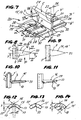
- Fig. 4 shows a mounting bracket 15, which looks at first glance similar to the clip 1 of FIG. The difference is to be seen in particular in that the clip 15 has not been formed from two welded together angles, but from a continuous metal strip to a T-profile. Also, the nails 6, 7, 7 'are not horizontally but vertically sclerosed, that is cut out and bent up, have a straight vertical nail spine 16 or nail comb and are trough-shaped downwardly open and they experience a high stiffening by this transverse curvature, so that, despite the long length of the nails, driving into hard wood is possible. In addition, they have conical-spatial shear edges 17 or shear surfaces 17 ', which cause the nail edge that the wood does not burst. The more precise nail shape will be described in more detail below in connection with other drawing figures.
- Fig. 5 shows a mounting bracket 18, which is basically the same with the bracket 15 of FIG. 4, except that now not angle soles 8,8 'are present with full length, but only half the length, which, like all Formations are center-symmetrically arranged on the bracket, so here offset by half the length.
- FIG. 6 shows a plan view of a sheet metal blank 19, from which the clamp 18 according to FIG. 5 is produced by appropriate bending / folding. It can be seen that the mutually protruding angle soles 8,8 'half length cut a material when cutting out of a correspondingly long sheet metal strip, are cut out of the several staple blanks in the longitudinal direction of the tape, each in the neck of a sole the sole of the subsequent blank formally accurate fits.
- a mounting bracket 20 (fourth embodiment), which is a more complex form of the clip 15 of FIG. 4.
- transverse bulging beads 21 and 22 are provided on the upper part of the web 5 on both sides, which together form a hollow web head 23.
- the two flat sheet metal parts are provided without a gap flat on top of each other, forming a gapless web foot 24.
- the nails 7, 7 ' are vertically sheared out of the web walls so that they protrude from the web foot 24 perpendicular and at the same time parallel to the angle soles 8,8', so that the nail feet 25 are in the Stegkopfflanken / -sicken ,
- the width 26 of the web head can be at least 5 mm, that is to say may have the optimum minimum distance between the planks.
- each two support and spacer beads 28 incorporated, which have a U-shaped cross-section. The two support beads 28 extend parallel to each other and are spaced from each other so that a mounting hole 9 is centrally inserted therebetween. Under the support beads 28 channels 29 are formed by the ventilation of the subsoil is optimized.
- a respective male connector 30 is provided at the respective outer front ends of the angle plates 8,8 ', which are formed by downward pushing of these edge zones and engage in the mounted state in the ground, as can be seen in particular from Fig. 17.
- a rectangular recess 31,31' is provided, which has extending in width extension male connectors 30, which are obtained by appropriate cutting and pressing down the sheet material, in particular from Fig. 18th is apparent.
- run-on slopes 34 are provided on the two longitudinal edges of the angle soles 8, 8 ', which can be seen in more detail from FIGS. 15 and 17.
- Fig. 8 shows a plan view of the shape of a nail 7 with the central straight back 16, the lateral shear edges 17 and shear surfaces 17 ', which extend parallel to each other first at the level of the nail base 25, then taper the nail conically and finally into a rounded tip 33 to leak.
- a similar design also has the nail 7 shown in Fig. 9, except that here the nail edges 17 'and the shear edges 17 are not pointed in a broken line, but in a relatively uniform arc-shaped tailing.
- Fig. 10 From Fig. 10 it can be seen how from the vertical wall 3 'of a double web 5 of the nail 7 is bent vertically from bottom to top and occupies a precisely vertical position, so that the nail back 16 has a straight, vertical course to the web wall 3. It can be seen that the lower side of the shear surface 17 'is pulled down towards the wall, resulting in a greater width in the zone of the nail base and thus a high rigidity of the nail as a whole, which 11 can also be seen, in which case also the downwardly drawn curved broadening of the nail is correspondingly recognizable.
- Fig. 12, 13 and 14 show the nail 7 in different sections and views and it is in each case the curly, downwardly open channel shape to recognize, with upper straight nail spine 16, the side conical, i.
- Fig. 15 From Fig. 15 it can be seen that the mounting holes 9 are formed in the angle soles 8 so that their countersink angle is greater than the screw head angle of the countersunk screw 12, whereby the weather-dependent work of the screed skewing the screw head and thus its tearing is avoided.
- FIG. 17 shows how, on an angle-soled side, which is equipped with a bead 28 on the one hand, which forms a ventilation channel 29 below itself, the outer edge or front edge is pressed downwards or deformed such that it appears claw-shaped in section Knife strip 30 is present, which incorporates the corresponding vertical pressure in the ground.
- Fig. 18 shows the incision 31 in the angle soles 8,8 ', whose transverse edges are pressed down so that also here male connectors 30 are formed, which also work claw-shaped into the ground.
- Fig. 19 shows a clip 35 (fifth embodiment) in cross-section, this clip being formed substantially like the clip 20 of Fig. 7, only here the web foot 24 is open and the nails 7, 7 'are aligned centrally on the web, ie aligned with one another.
- the web foot opening 36 is at least about 0.5 mm, so that this opening together with the cavity of the web head 23 form a ventilation channel, whereby the planks and the plank substrate are optimally ventilated. Since a transverse elasticity of the clip is also provided by the hollow web head and the opening 36, which makes a wrapping of the clip on a screed not optimally executable, an opening 37 is provided on the Einschlag nail 7 arranged counter wall 14.
- a pin of a wrapping tool 38 extends through it so that its end face on the back of the wall on which protrudes the nail 7 protrudes, pending and counteracts or transfers the impact force directly on the wall on the nail 7. It can be seen that with each central arrangement of the two nails 7,7 ', so aligned alignment, the tool 38 on the one hand engages a nail 7' on the pin 39 and on the other hand the front side a recess 40, in which the nail 7 ' protrudes, owns.
- Fig. 20 shows a similar construction as Fig. 19, except that here the web 5 is very strongly opened, so has a large width 26 of the web head and a large web foot opening 36. Since in the embodiment illustrated here, no aligned central arrangement of the nails 7,7 ', but a longitudinally offset execution, as described above and shown (point symmetry), is present, and the opening 37 may be introduced at the same height with the nail 7, so that the turning tool 38 with its pin 39 exactly on the nail foot 25 of the nail 7 supporting or driving action acts.
- a mounting bracket 42 can be seen, which - also as described above staple designs - is composed of two L-profiles and also has a center symmetry, so that here with the left or right side can be started during assembly.
- the peculiarity of this embodiment is that the two L-profiles are no longer firmly connected to each other, but only loose individual profiles are that interlocking interlocking in pairs to form a staple unit pushed together.
- the two identical clip profiles 2, 2 ' have centrally in the vertical legs 3, 3', which form the double web 5 in the assembled state shown in Fig. 21, each have a nail 7, 7 ', thus arranged in alignment with each other in the transverse direction and whose training has already been described in detail above.
- each one guide tongue 44, 44 'extends horizontally and transversely displaceable, as well as more clearly from Fig. 23 can be seen.
- the guide tongues are bent outwards and bent out by 90 ° to align with the respective angle soles.
- the soles 8, 8 'each have a mounting hole 9, 9', which can also be designed as a transverse slot.
- a vertically projecting notch or bulge 47, 47 ' is provided on the beads 28 and 43, which serves to increase the Ausziehwiederstandes resting in the assembled state planks.
- the top of the notches are obliquely rising in the direction of the vertical leg 3, 3 'executed; but it can also be formed parallel to the support surface and widen conically towards the vertical leg.
- two notched nails are provided in a symmetrical arrangement to the nail 7, 7 '.
- Fig. 22 shows the mounting bracket 42 of Fig. 21, but in the transverse direction apart pushed state of the bracket forming angle sections 2, 2 '.
- the shape of the guide tongues 44, 44 ' can be seen particularly clearly by outward bending and bending out in the opposite direction to the respective angle sole 8, 8'.
- second guide elements as shown in Fig. 21, but simple rectangular guide cutouts 45, 45 '.
- the two angle sections 2, 2 ' are identical, which brings great advantages both in the production and during assembly.
- the tongues 44, 44 'each have a mounting hole 46, 46' available, which allow the use of the angle profiles as the beginning or end pieces.
- Notches 47, 47 ' are also provided in the angle soles 8, 8', specifically in the center, under the nail 7, 7 '.
- Fig. 23 shows a mounted on a substrate 13, mounted bracket 42 with planks 11, 11 '. It can be seen how the planks 11, 11 'rest with driven nails 7, 7' on the beads 43 and 28 and the notching nails 47, 47 'are pressed into the plank bottom.
- the guide tongue 44 of the right angle section 2 ' extends into the guide opening of the guide bead 43 of the left angle section 2.
- the two angle sections 2, 2 ' are pushed into each other by means of the guide tongues and mounted as a unit.
- the two vertical legs 2, 2 'patch exposed at the location of the nail exposed pressure body and mounted with the hammer or a press tool. It can be mounted equally from right to left as well as from left to right.
- the second angle plate is fastened to the substrate 13 z: for example with a screw 12. Then the next screed is attached to the free nail and hammered or pressed. Now the process repeats itself.
- the object of the invention is in the construction industry for connecting wood components with each other and on a substrate, in particular of Planks of balcony and patio coverings in the open, or of beams, suitable for commercial use.
Landscapes
- Engineering & Computer Science (AREA)
- Architecture (AREA)
- General Engineering & Computer Science (AREA)
- Mechanical Engineering (AREA)
- Civil Engineering (AREA)
- Structural Engineering (AREA)
- Life Sciences & Earth Sciences (AREA)
- Wood Science & Technology (AREA)
- Joining Of Building Structures In Genera (AREA)
- Floor Finish (AREA)
- Connection Of Plates (AREA)
Claims (26)
- Bride de fixation servant à l'assemblage d'éléments de construction en bois entre eux et sur un support, notamment de madriers de chapes de balcon et de terrasses, de préférence en plein air, comportant- un entretoise (5),- au moins un clou respectivement sous forme de languette pointue (6,6',7,7') qui saille perpendiculairement/horizontalement des deux côtés de l'entretoise dans sa partie supérieure- des semelles d'équerre (8,8') saillissant perpendiculairement/horizontalement des deux côtés de l'entretoise dans sa partie inférieure,caractérisée en ce que- la bride de fixation (1, 15, 18, 20, 35, 42) est une équerre double composée de deux profilés en L (2,2'),- l'entretoise (5) est une entretoise double composée de deux branches de profilé (3,3'),et qu'au moins un trou de fixation (9,9') est prévu dans au moins l'une des semelles d'équerre (8,8').
- Bride de fixation selon la revendication 1, caractérisée en ce que les deux profilés en L (2,2') de la bride (1) sont fixés l'un contre l'autre de façon plane par leurs branches verticales (3,3'), par soudage, rivetage ou d'autres techniques d'assemblage, pour former un profilé en T horizontal.
- Bride de fixation selon la revendication 1, caractérisée en ce que la bride (15, 18, 20, 35) est façonnée par pliage comme profilé en T à partir d'une bande métallique continue.
- Bride de fixation selon la revendication 1, caractérisée en ce que les clous en forme de languettes (6, 6',7,7') sont disposés à proximité de l'extrémité supérieure de l'entretoise, découpés de la paroi de l'entretoise (3,3') et saillissent perpendiculairement de cette dernière.
- Bride de fixation selon la revendication 4, caractérisée en ce que chaque côté de l'entretoise présente un clou (6,6' et 7,7' respectivement), disposés l'un par rapport à l'autre de façon décalée symétriquement par rapport au milieu (10) du développement longitudinal de l'entretoise (5).
- Bride de fixation selon la revendication 4, caractérisée en ce que les clous (6,6',7,7') sont découpés des parois de l'entretoise (3,3') et en saillissent horizontalement ou verticalement, à savoir parallèlement ou perpendiculairement par rapport aux semelles d'équerre (8,8').
- Bride de fixation selon la revendication 4, caractérisée en ce que les clous (6,6',7,7') sont réalisés sous forme de rigole ou d'arc, arqués au niveau du pied du clou (25) et en cône vers la pointe (33), ressemblant à un bec d'oiseau droit à rayon réduit à la pointe (33), les arêtes latérales ou de cisaillement (17) et les surfaces de cisaillement (17') entre celles-ci subissant un cintrage dans l'espace par rapport à la verticale d'env. 45° au niveau du pied jusqu'à 0° au niveau de la pointe du clou (33).
- Bride de fixation selon la revendication 1, caractérisée en ce que à la partie extérieure supérieure de l'entretoise double (5), un bombement transversal sous forme de moulure (21,22) est prévu des deux côtés qui s'étend longitudinalement, les deux bombements formant ensemble une moulure double creuse, à savoir une tête d'entretoise (23) dont sortent les clous (6,6',7,7').
- Bride de fixation selon la revendication 8, caractérisée en ce que pour une épaisseur de matériau d'env. 1,5 mm, la largeur (26) de la tête d'entretoise (23) est d'au moins 5 mm.
- Bride de fixation selon la revendication 8, caractérisée en ce que l'entretoise (5) est fermée, à savoir les tôles d'entretoise se touchent, ou ouverte, à savoir les tôles sont disposées avec un écart (36) d'au moins 0,5 mm l'une par rapport à l'autre formant ainsi un pied d'entretoise (24) ouvert.
- Bride de fixation selon la revendication 10, caractérisée en ce que les clous (7,7'), tout au moins les pieds de clou (25), sont disposés sur la tête d'entretoise (23) et que, sur la contre-paroi de la paroi de la tête d'entretoise portant le clou, un orifice (37) est prévu pour faire passer un outil à enfoncer (38).
- Bride de fixation selon la revendication 1, caractérisée en ce que la largeur des semelles d'équerre (8,8') est supérieure à la longueur des clous (6,6',7,7'), de préférence du double.
- Bride de fixation selon la revendication 1, caractérisée en ce que les semelles d'équerre (8,8') présentent la même longueur que l'entretoise double (5), ou seulement la demi-longueur de cette dernière, les deux demi-semelles étant disposées l'une par rapport à l'autre de façon décalée de la moitié de la longueur de l'entretoise, faisant saillie en alternance, en symétrie centrale.
- Bride de fixation selon la revendication 1, caractérisée en ce que au moins une élévation dirigée vers les clous se présentant sous forme d'une moulure d'appui (28) qui s'étend en direction transversale ou sur la largeur de la semelle, est prévue sur chacune des semelles d'équerre (8,8'), lesdites moulures pouvant présenter une section en forme d'arc, de toit ou en U.
- Bride de fixation selon la revendication 14, caractérisée en ce que deux moulures (28) sont disposées parallèlement sur chaque semelle d'équerre (8.8'), et que les trous de fixation (9,9') sont aménagés au milieu de l'intervalle entre lesdites moulures.
- Bride de fixation selon la revendication 1, caractérisée en ce que le trou de fixation (9,9') est fraisé en cône pour recevoir au moins partiellement la tête conique d'une vis à tête fraisée (12) et que l'angle de fraisure est plus grand que l'angle de la tête de vis.
- Bride de fixation selon la revendication 1, caractérisée en ce que les trous de fixation (9,9') sont des trous oblongs s'étendant dans le sens transversal.
- Bride de fixation selon la revendication 1, caractérisée en ce que les extrémités longitudinales des semelles d'équerre (8,8') présentent des chanfreins de glissage (34) dans le sens d'insertion des madriers qui s'étendent également sur les extrémités correspondantes des moulures (28).
- Bride de fixation selon la revendication 1, caractérisée en ce que les semelles d'équerre (8,8') présentent au moins un rebord à lame en forme de crampon (30) qui est formé et replié vers le bas à partir desdites semelles.
- Bride de fixation selon la revendication 19, caractérisée en ce que les rebords à lame (30) sont prévus sur les deux arêtes latérales des semelles d'équerre (8,8'), au moins à l'extrémité avant de celles-ci sur une longueur d'au moins un sixième de la largeur de la semelle.
- Bride de fixation selon la revendication 19, caractérisée en ce que dans la zone centrale des semelles d'équerre (8,8') est prévu un évidement rectangulaire essentiellement en U (31) dont la profondeur est égale à une fraction de la largeur de la semelle, les arêtes latérales s'étendant dans le sens transversal des semelles étant repliées vers le bas en tant que rebords à lame en forme de crampon (30).
- Bride de fixation selon la revendication 1, caractérisée en ce que la bride (42) consiste en deux profilés en L détachés (2,2') qui peuvent être assemblés ou reliés entre eux de sorte que, de par leur forme, les profilés s'engagent l'un dans l'autre de façon à ce que les profilés puissent se déplacer au moins légèrement l'un par rapport à l'autre dans le sens transversal, mais pas dans le sens longitudinal.
- Bride de fixation selon la revendication 22, caractérisée en ce que, pour permettre que les deux profilés (2,2') de la bride puissent s'engager l'un dans l'autre, ceux-ci comportent des éléments de guidage transversal (43,44,45) consistant d'une part en une languette de guidage (44) faisant saillie de l'entretoise (3,3') et d'autre part en un orifice de guidage (43 et 45 respectivement) prévu dans le contre-profilé en alignement avec ladite languette.
- Bride de fixation selon la revendication 23, caractérisée en ce que les languettes de guidage (44) sont des rectangles découpés de l'entretoise du profilé (3,3') qui en font saillie perpendiculairement et s'alignent aux semelles d'équerre, tandis que les orifices de guidage sont ou des découpes (45) s'étendant transversalement à travers les entretoises jusque dans les semelles d'équerre ou des moulures de guidage (43).
- Bride de fixation selon la revendication 23 et selon au moins l'une quelconque des revendications précédentes, caractérisée en ce que le clou (7,7') prévu sur chaque profilé (2,2') est disposé au milieu de la branche du profilé, tandis que les moyens de guidage sont prévus décalés par rapport au milieu.
- Bride de fixation selon la revendication 24, caractérisée en ce que sur les surfaces d'appui des madriers, à savoir sur les semelles d'équerre (8,8') ou les moulures (43,45), est disposée au moins une saillie ou encoche (46,46') qui, comme un clou, fait saillie, et qui présentent une inclinaison en direction de l'entretoise ou dont la face supérieure est parallèle à la surface supérieure de la semelle ou de la moulure et dont la partie inférieure s'élargit de façon conique dans le même sens.
Applications Claiming Priority (5)
| Application Number | Priority Date | Filing Date | Title |
|---|---|---|---|
| DE20112018U DE20112018U1 (de) | 2001-07-16 | 2001-07-16 | Doppelwinkelplatte |
| DE20112018U | 2001-07-16 | ||
| DE10157807 | 2001-11-27 | ||
| DE10135274 | 2001-11-27 | ||
| PCT/EP2002/007667 WO2003009138A2 (fr) | 2001-07-16 | 2002-07-10 | Bride de fixation servant a l'assemblage d'elements de construction en bois |
Publications (2)
| Publication Number | Publication Date |
|---|---|
| EP1407357A2 EP1407357A2 (fr) | 2004-04-14 |
| EP1407357B1 true EP1407357B1 (fr) | 2006-09-20 |
Family
ID=26010653
Family Applications (1)
| Application Number | Title | Priority Date | Filing Date |
|---|---|---|---|
| EP02754861A Expired - Lifetime EP1407357B1 (fr) | 2001-07-16 | 2002-07-10 | Bride de fixation servant a l'assemblage d'elements de construction en bois |
Country Status (10)
| Country | Link |
|---|---|
| US (1) | US7251918B2 (fr) |
| EP (1) | EP1407357B1 (fr) |
| JP (1) | JP4077791B2 (fr) |
| CN (1) | CN1328445C (fr) |
| AT (1) | ATE340385T1 (fr) |
| AU (1) | AU2002321200A1 (fr) |
| CA (1) | CA2453656C (fr) |
| DE (1) | DE10230797C2 (fr) |
| ES (1) | ES2271310T3 (fr) |
| WO (1) | WO2003009138A2 (fr) |
Cited By (1)
| Publication number | Priority date | Publication date | Assignee | Title |
|---|---|---|---|---|
| DE102007024775B3 (de) * | 2007-05-26 | 2008-11-27 | HV-Group GbR (vertretungsberechtigter Gesellschafter Herr Stefan Scheifele Hagenbühlstr.6, 87757 Kirchheim) | Befestigungssystem zum Verbinden von Holzbauteilen |
Families Citing this family (72)
| Publication number | Priority date | Publication date | Assignee | Title |
|---|---|---|---|---|
| CN1093535C (zh) * | 1994-09-26 | 2002-10-30 | 盐野义制药株式会社 | 咪唑衍生物 |
| DE10230797C2 (de) | 2001-07-16 | 2003-09-25 | Dieter Reif | Befestigungsklammer zur Verbindung von Holzbauteilen |
| US7207150B2 (en) | 2003-06-12 | 2007-04-24 | Simpson Strong-Tie Company, Inc. | Deck board tie connector, connection and method |
| US7398623B2 (en) * | 2004-05-12 | 2008-07-15 | Tiger Claw, Inc. | Deck board fastener with concave prongs |
| EP1619321A1 (fr) | 2004-07-22 | 2006-01-25 | Sika Technology AG | Revêtement de terrasses et procédé de fixation des planches à une structure sous-jacente du revêtement de terrasses |
| AT414029B (de) | 2004-08-04 | 2006-08-15 | Fuchs Dietrich Anton | Befestigung von bohlen an einer unterkonstruktion |
| DE102004061437B4 (de) * | 2004-12-17 | 2007-05-03 | Dieter Reif | Befestigungsklammer zur Verbindung von Holzbauteilen |
| DE102005019719B4 (de) * | 2005-04-25 | 2010-01-28 | Hubert Nowack | Verbindungsanordnung in einem aus Konstruktionsteilen gebildeten Tragwerk, Verbindungssystem sowie Verbindungsmittel |
| CA2556378A1 (fr) * | 2005-08-19 | 2007-02-19 | Handy & Harman | Systeme d'attache a tablier cache |
| DE102005049719B3 (de) * | 2005-10-14 | 2007-05-03 | Dieter Reif | Befestigungselement für auswechselbare Holzteile wie Bohlen |
| AT503241B1 (de) * | 2005-10-24 | 2011-02-15 | Neuhofer Franz Jun | Vorrichtung zum stirnseitigen abschliessen eines bodenbelages |
| US7805902B2 (en) * | 2006-03-23 | 2010-10-05 | Tiger Claw, Inc. | Fastener for grooved or slotted decking members |
| JP4781907B2 (ja) * | 2006-05-23 | 2011-09-28 | フクビ化学工業株式会社 | デッキ材、デッキ構造、デッキ組み立て方法およびデッキフロア |
| US20100146900A1 (en) * | 2006-07-28 | 2010-06-17 | Allan Holland | connector |
| DE102006035805B3 (de) * | 2006-08-01 | 2007-11-08 | Markus Rensburg | Bohlenverbindungselement |
| DE202006012772U1 (de) * | 2006-08-19 | 2007-12-27 | Stefan Ehrenreich Gmbh | Vorrichtung zur Befestigung von Bohlen auf einer Unterkonstruktion |
| WO2008058311A1 (fr) * | 2006-11-14 | 2008-05-22 | Srb Constructions Technologies Pty Ltd | Moyen de garniture de joint pour panneau moulé |
| DE102007013087A1 (de) * | 2006-11-24 | 2008-05-29 | Nupfahl Gmbh & Co. Kg | Verfahren zum Verlegen von flächig begrenzten Bodenbelägen und Vorrichtung zur Verhinderung von Verschiebebewegungen |
| DE102007009477B3 (de) | 2007-02-23 | 2008-10-30 | Ulrich Reif | Befestigungsklammer zur Verbindung von Holzbauteilen und Verfahren zu deren Herstellung |
| US20080224002A1 (en) * | 2007-03-15 | 2008-09-18 | Klaus Butow | Truss Bracket |
| US8555566B2 (en) | 2007-08-06 | 2013-10-15 | California Expanded Metal Products Company | Two-piece track system |
| US10563399B2 (en) | 2007-08-06 | 2020-02-18 | California Expanded Metal Products Company | Two-piece track system |
| US8087205B2 (en) | 2007-08-22 | 2012-01-03 | California Expanded Metal Products Company | Fire-rated wall construction product |
| US10619347B2 (en) | 2007-08-22 | 2020-04-14 | California Expanded Metal Products Company | Fire-rated wall and ceiling system |
| DE102008018072B3 (de) * | 2007-10-24 | 2009-03-26 | Ulrich Reif | Vorrichtung zum Verlegen von Brettern für z.B. Terrassenbeläge |
| US8672600B2 (en) * | 2008-02-07 | 2014-03-18 | Tinnerman Palnut Engineered Products, Inc. | Deck clip |
| EP2096232A1 (fr) | 2008-02-27 | 2009-09-02 | Nmc S.A. | Dispositif d'attache |
| DE102009031825B4 (de) | 2009-07-03 | 2011-03-31 | hülsta-werke Hüls GmbH & Co KG | Befestigungsklammer, Belag und Diele |
| US8146303B2 (en) * | 2009-09-21 | 2012-04-03 | Brent Alan Gibson | Integrated decking member fastening track |
| US8671632B2 (en) | 2009-09-21 | 2014-03-18 | California Expanded Metal Products Company | Wall gap fire block device, system and method |
| US10005585B2 (en) * | 2009-12-08 | 2018-06-26 | Chep Technology Pty Limited | Wooden pallet with nail plates and related methods |
| US20110173901A1 (en) * | 2010-01-21 | 2011-07-21 | Brock Usa, Llc | Self Supporting Paver System |
| US10184246B2 (en) | 2010-04-08 | 2019-01-22 | California Expanded Metal Products Company | Fire-rated wall construction product |
| AT509874B1 (de) | 2010-08-03 | 2011-12-15 | Sihga Handels Gmbh | Befestigung von bohlen an einer unterkonstruktion |
| EP2635750B1 (fr) * | 2010-11-01 | 2016-08-03 | AWI Licensing Company | Système de plafond suspendu, éléments de fixation et procédé d'installation d'un système de plafond suspendu |
| KR101051069B1 (ko) | 2011-01-25 | 2011-07-22 | 주식회사 대라 | 목재데크 체결장치 |
| IT1404469B1 (it) * | 2011-02-10 | 2013-11-22 | Ceccato & Co | Guida deformabile per divisori in genere |
| AU2011201974A1 (en) * | 2011-03-08 | 2012-09-27 | Turner, Arthur Raymond Mr | Building Means |
| US8800232B1 (en) * | 2011-04-04 | 2014-08-12 | LEK Innovations, LLC | Flange shear connection for precast concrete structures |
| US8615958B2 (en) * | 2011-07-13 | 2013-12-31 | A. Raymond Et Cie | Stepped hidden decking system with fastener |
| US10077550B2 (en) | 2012-01-20 | 2018-09-18 | California Expanded Metal Products Company | Fire-rated joint system |
| DE202012002870U1 (de) | 2012-03-20 | 2012-05-03 | Ulrich Reif | Befestigungsklammer zur Verbindung von Bauteilen |
| CA2823847C (fr) * | 2012-08-20 | 2019-11-26 | Sigma Dek Ltd. | Attache de fixation d'element de plancher |
| US9334672B1 (en) * | 2013-04-27 | 2016-05-10 | Scott Robert Mallory | Bracket for hanging a rail and method |
| AT13835U1 (de) | 2013-08-12 | 2014-09-15 | Sihga Handels Gmbh | Befestigung von Bohlen an einer Unterkonstruktion |
| AT14495U1 (de) | 2014-05-23 | 2015-12-15 | Stinglmair Stefan | Vorrichtung zum Befestigen von Profilen an einer Unterkonstruktion |
| DE202014004575U1 (de) | 2014-05-24 | 2014-07-21 | Markus Rensburg | Montageklammer |
| DE202014006016U1 (de) | 2014-07-24 | 2014-09-10 | Markus Rensburg | Montageklammer |
| DE102014011022B4 (de) | 2014-07-24 | 2019-02-14 | Markus Rensburg | Montageklammer |
| BR112017004547B1 (pt) * | 2014-09-08 | 2022-04-26 | Becton, Dickinson And Company | Sistema para a preparação de um composto farmacêutico e para avaliação e verificação de referida preparação |
| US9879421B2 (en) * | 2014-10-06 | 2018-01-30 | California Expanded Metal Products Company | Fire-resistant angle and related assemblies |
| US9752318B2 (en) | 2015-01-16 | 2017-09-05 | California Expanded Metal Products Company | Fire blocking reveal |
| US10000923B2 (en) | 2015-01-16 | 2018-06-19 | California Expanded Metal Products Company | Fire blocking reveal |
| CA2919348A1 (fr) | 2015-01-27 | 2016-07-27 | California Expanded Metal Products Company | Guide principal dote de fonctionnalite de retenue de montant |
| SE541774C2 (en) * | 2017-03-23 | 2019-12-10 | Jilken Leif | Modular pier and attachment system for modular pier |
| US20180371752A1 (en) * | 2017-06-23 | 2018-12-27 | Bruce Tiefel | Intermediate Wood Wall Support System called Straight Wall |
| US20190077088A1 (en) * | 2017-09-14 | 2019-03-14 | GM Global Technology Operations LLC | Amalgamation plates for joining components |
| EP3456892B1 (fr) * | 2017-09-18 | 2023-06-21 | Knapp GmbH | Connecteur pour deux pièces à assembler |
| US20190100931A1 (en) * | 2017-10-04 | 2019-04-04 | Humberto Rodriguez | Drywall repair fastener and method of using the same |
| DE202018100307U1 (de) * | 2018-01-19 | 2018-01-29 | Peri Gmbh | Metall-Schalungsträger mit Schutz vor klimatischen Einflüssen |
| DE102018104121B4 (de) * | 2018-02-23 | 2021-12-02 | ACO Severin Ahlmann GmbH & Co Kommanditgesellschaft | Stütz- und Verstärkungselement, Flachblech, Entwässerungssystem und Verfahren zur Herstellung |
| US10753084B2 (en) | 2018-03-15 | 2020-08-25 | California Expanded Metal Products Company | Fire-rated joint component and wall assembly |
| US10689842B2 (en) | 2018-03-15 | 2020-06-23 | California Expanded Metal Products Company | Multi-layer fire-rated joint component |
| CA3041494C (fr) | 2018-04-30 | 2022-07-05 | California Expanded Metal Products Company | Bouchon a cannelures coupe-feu fixe mecaniquement |
| US20200031524A1 (en) * | 2018-07-24 | 2020-01-30 | Chep Technology Pty Limited | Wooden pallet with end deck boards and butted spacers |
| US11111666B2 (en) | 2018-08-16 | 2021-09-07 | California Expanded Metal Products Company | Fire or sound blocking components and wall assemblies with fire or sound blocking components |
| US11111677B2 (en) * | 2018-09-19 | 2021-09-07 | Fiber Composites, Llc | Siding clip |
| CN109736535A (zh) * | 2018-11-26 | 2019-05-10 | 浙江亚厦装饰股份有限公司 | 实铺基板及基板组件 |
| US10914065B2 (en) | 2019-01-24 | 2021-02-09 | California Expanded Metal Products Company | Wall joint or sound block component and wall assemblies |
| US11268274B2 (en) | 2019-03-04 | 2022-03-08 | California Expanded Metal Products Company | Two-piece deflection drift angle |
| CN110130611A (zh) * | 2019-06-20 | 2019-08-16 | 黄国涛 | 一种木地板连接结构及连接方法 |
| US11920343B2 (en) | 2019-12-02 | 2024-03-05 | Cemco, Llc | Fire-rated wall joint component and related assemblies |
Family Cites Families (80)
| Publication number | Priority date | Publication date | Assignee | Title |
|---|---|---|---|---|
| US441227A (en) * | 1890-11-25 | Box-strap | ||
| US282164A (en) * | 1883-07-31 | Albbbt chase | ||
| US407376A (en) * | 1889-07-23 | |||
| US956347A (en) * | 1907-04-02 | 1910-04-26 | Emanuel S Heller | Bond-plate for building construction. |
| US876399A (en) * | 1907-05-09 | 1908-01-14 | Henry L Robinson | Tile-fastener. |
| US924355A (en) * | 1908-08-17 | 1909-06-08 | Silas Frank | Joint for floor-coverings. |
| US1241885A (en) * | 1916-02-24 | 1917-10-02 | Charles Roeder | Tiling construction. |
| US1474046A (en) * | 1919-10-24 | 1923-11-13 | Henry H Lampert | Wall tie |
| US1366470A (en) * | 1920-01-23 | 1921-01-25 | Henry H Lampert | Wall-tie |
| GB182872A (en) * | 1921-03-31 | 1922-06-30 | Edwin Vaughan | Means for securing boards together at their ends both edgewise and at an angle |
| US1783391A (en) * | 1926-10-30 | 1930-12-02 | Commw Electric Company | Insert |
| US1762254A (en) * | 1929-03-18 | 1930-06-10 | Zarba Joseph | Straightedge and reenforcing device |
| US1922945A (en) * | 1930-11-25 | 1933-08-15 | William J Gravert | Fastener for fire brick and the like |
| US1879457A (en) * | 1931-03-27 | 1932-09-27 | Carley H Paulsen | Fastening means for wall and ceiling boards |
| US1870011A (en) * | 1931-03-31 | 1932-08-02 | Johnson John Clement | Erecting strip for building materials |
| US2045936A (en) * | 1932-05-20 | 1936-06-30 | Anthony Casciani | Construction of terrazzo and like floors |
| US1974259A (en) | 1932-06-18 | 1934-09-18 | Lug Lox Floering Company | Floor board and fastening therefor |
| US2116737A (en) * | 1934-07-16 | 1938-05-10 | Leon F Urbain | System for laying boards |
| US2129975A (en) * | 1935-05-11 | 1938-09-13 | Leon F Urbain | Acoustical tile clip |
| US2066813A (en) * | 1936-02-26 | 1937-01-05 | Frederick W Williams | Fastening device |
| US2216271A (en) * | 1939-08-02 | 1940-10-01 | Harvey L Joiner | Shingle joiner or shingle-butt-end clip |
| US2272762A (en) * | 1939-12-11 | 1942-02-10 | Awbrey William Powell | Base screed |
| US2447694A (en) * | 1944-07-06 | 1948-08-24 | Harold L Finch | Ceiling and wall construction |
| US2476506A (en) * | 1945-03-07 | 1949-07-19 | Anders C Olsen | Combination fastening device |
| US2620705A (en) * | 1946-08-03 | 1952-12-09 | William J Papa | Fastening device |
| FR1120223A (fr) * | 1955-01-20 | 1956-07-03 | Revêtement préfabriqué | |
| US2848758A (en) * | 1955-03-15 | 1958-08-26 | Gordon R Chisholm | Wall board securing cleat |
| US2915795A (en) * | 1955-10-06 | 1959-12-08 | Owens Corning Fiberglass Corp | Insulating joint construction |
| US3089570A (en) * | 1959-07-21 | 1963-05-14 | Jr Timothy H O'neil | Beam and tie support |
| US3276797A (en) * | 1961-12-06 | 1966-10-04 | Parametrics Res & Dev Co Inc | Spline fastening device |
| US3267624A (en) * | 1963-05-31 | 1966-08-23 | Fenestra Inc | Composite panel with concrete backer and hanging members |
| GB1113244A (en) * | 1963-11-19 | 1968-05-08 | Nicholas Fleischmann | Improvements in or relating to the production of floor or wall panelling |
| US3348346A (en) * | 1965-10-19 | 1967-10-24 | Milwaukee Ferrometal Stamping | Bracket for mounting parts on masonry |
| US3407547A (en) * | 1966-07-20 | 1968-10-29 | Angeles Metal Trim Co | Metallic wall stud structure for supporting shelf brackets |
| US3553919A (en) * | 1968-01-31 | 1971-01-12 | Omholt Ray | Flooring systems |
| US3565473A (en) * | 1968-10-08 | 1971-02-23 | Eastern Prod Corp | Hold-down clip for tiles in suspended ceiling structure |
| US3577694A (en) * | 1969-08-18 | 1971-05-04 | Powerlock Floors Inc | Flooring systems |
| US3606414A (en) * | 1969-08-22 | 1971-09-20 | Osmose Wood Preserving Co | Fastener |
| US3759001A (en) * | 1971-09-23 | 1973-09-18 | Eastern Prod Corp | Demountable wall construction |
| US3828514A (en) * | 1971-10-08 | 1974-08-13 | Automated Building Components | Structural joint and connector plate therefor |
| SE374714B (fr) | 1973-01-10 | 1975-03-17 | Nefab Plywoodemballage Ab | |
| US3875719A (en) * | 1973-07-05 | 1975-04-08 | Troy Steel Corp | Metal support for wood structural elements |
| US4157676A (en) * | 1977-09-30 | 1979-06-12 | Automated Building Components, Inc. | Lap-joint fastener |
| US4235148A (en) * | 1977-12-19 | 1980-11-25 | Menge Richard J | Connector plate |
| US4339903A (en) * | 1977-12-19 | 1982-07-20 | Menge Richard J | Metal cross support |
| US4157002A (en) * | 1977-12-27 | 1979-06-05 | Adolph Floyd L | Cross bracing for wood truss building wall construction and the like |
| US4246852A (en) * | 1979-06-21 | 1981-01-27 | General Signal Corporation | Industrial furnace with ceramic insulating modules |
| US4318652A (en) * | 1979-06-29 | 1982-03-09 | Truswal Systems Corporation | Connector plate |
| US4389190A (en) * | 1981-08-18 | 1983-06-21 | Sevink Theodor J | Support of suspension of insulating material |
| NZ198727A (en) * | 1981-10-21 | 1983-11-30 | A R Turner | Adjustable bracing element |
| US4479341A (en) * | 1982-04-02 | 1984-10-30 | Fastway Fasteners, Inc. | Clips for T-bar grid ceiling arrangement |
| US4498272A (en) * | 1982-05-20 | 1985-02-12 | Rollform, Incorporated | Panel fastener |
| US4553363A (en) * | 1982-09-23 | 1985-11-19 | Weinar Roger N | Outside wallboard corner construction and edging member for said corners |
| US4489529A (en) * | 1983-01-17 | 1984-12-25 | Armstrong World Industries, Inc. | Reinforced ceiling runner |
| US4558549A (en) * | 1984-04-19 | 1985-12-17 | See Jacques L | Wall construction prefabricated from interconnectable modules |
| US4703601A (en) * | 1984-10-01 | 1987-11-03 | Abendroth Carl W | Fastener for flooring systems |
| US4616462A (en) * | 1984-10-01 | 1986-10-14 | Abendroth Carl W | Fastener for flooring systems |
| US4620403A (en) | 1984-10-10 | 1986-11-04 | Field Gerald L | Nailing anchor and method of use |
| US4641474A (en) * | 1985-09-11 | 1987-02-10 | Cannarsa Robert C | Sta-put wallboard joiner |
| FI74319C (fi) * | 1986-02-13 | 1988-01-11 | Metsae Serla Oy | Fogorgan foer fogning av traebalkar vid varandra. |
| US4712350A (en) * | 1986-05-16 | 1987-12-15 | Chicago Metallic Corporation | Centering arrangement for T members of a suspended ceiling |
| US4711183A (en) * | 1986-08-01 | 1987-12-08 | Hirsh Company | Shelving assembly with drop-in shelf |
| US4941340A (en) * | 1987-01-09 | 1990-07-17 | E. Vassiliou | Method of fabricating wall fasteners |
| US4815886A (en) * | 1987-11-20 | 1989-03-28 | Madsen Evan L | Expansion joint for concrete and method for use |
| US4925141A (en) * | 1988-10-17 | 1990-05-15 | Mickey Classen | Deck clip |
| US5027573A (en) * | 1989-05-01 | 1991-07-02 | Simpson Strong-Tie Company, Inc. | Deck clip system, method and connector connection |
| US5454203A (en) * | 1990-08-30 | 1995-10-03 | Saf-T-Corp | Frame brace |
| US5154536A (en) * | 1991-05-31 | 1992-10-13 | Jeffrey Ciudaj | Adjustable screed rail |
| US5279091A (en) * | 1992-06-26 | 1994-01-18 | Williams Mark F | Building enclosure assemblies |
| US5588629A (en) * | 1995-05-22 | 1996-12-31 | Barnes; Renny H. | Wall article hanging device |
| JP3480129B2 (ja) * | 1995-06-28 | 2003-12-15 | ソニー株式会社 | 二軸アクチェータ及び光学ピックアップ |
| US5910087A (en) * | 1997-01-17 | 1999-06-08 | Carter; Randy A. | Control joint for forming concrete |
| US5966892A (en) * | 1997-01-27 | 1999-10-19 | Platt; R. Terry | Ready to assemble wood construction system |
| JPH111961A (ja) * | 1997-06-10 | 1999-01-06 | Tanaka:Kk | 木造建築における仕口装置 |
| US5974753A (en) * | 1998-06-18 | 1999-11-02 | Hsu; Oscar Hsien-Hsiang | Detachable free mounting wall system |
| US6364374B1 (en) * | 1999-10-27 | 2002-04-02 | Michael J. Noone | Methods and devices for joining panels |
| US6416269B1 (en) * | 2000-10-25 | 2002-07-09 | David Martel | Fastener for securing decking boards to an underlying supporting member |
| US6490838B2 (en) * | 2001-01-19 | 2002-12-10 | Jeffry L. Summerford | Above-grade decking system |
| DE10230797C2 (de) | 2001-07-16 | 2003-09-25 | Dieter Reif | Befestigungsklammer zur Verbindung von Holzbauteilen |
| DE10230737A1 (de) | 2002-07-09 | 2004-01-29 | Ibs Brocke Gmbh & Co. Kg | Beschneidevorrichtung zum Be-und Zuschneiden von Werkstücken |
-
2002
- 2002-07-08 DE DE10230797A patent/DE10230797C2/de not_active Expired - Fee Related
- 2002-07-10 ES ES02754861T patent/ES2271310T3/es not_active Expired - Lifetime
- 2002-07-10 JP JP2003514414A patent/JP4077791B2/ja not_active Expired - Fee Related
- 2002-07-10 AT AT02754861T patent/ATE340385T1/de active
- 2002-07-10 CA CA002453656A patent/CA2453656C/fr not_active Expired - Fee Related
- 2002-07-10 EP EP02754861A patent/EP1407357B1/fr not_active Expired - Lifetime
- 2002-07-10 US US10/484,915 patent/US7251918B2/en not_active Expired - Fee Related
- 2002-07-10 CN CNB02816363XA patent/CN1328445C/zh not_active Expired - Fee Related
- 2002-07-10 AU AU2002321200A patent/AU2002321200A1/en not_active Abandoned
- 2002-07-10 WO PCT/EP2002/007667 patent/WO2003009138A2/fr active IP Right Grant
Cited By (1)
| Publication number | Priority date | Publication date | Assignee | Title |
|---|---|---|---|---|
| DE102007024775B3 (de) * | 2007-05-26 | 2008-11-27 | HV-Group GbR (vertretungsberechtigter Gesellschafter Herr Stefan Scheifele Hagenbühlstr.6, 87757 Kirchheim) | Befestigungssystem zum Verbinden von Holzbauteilen |
Also Published As
| Publication number | Publication date |
|---|---|
| JP4077791B2 (ja) | 2008-04-23 |
| EP1407357A2 (fr) | 2004-04-14 |
| AU2002321200A8 (en) | 2003-03-03 |
| JP2005508463A (ja) | 2005-03-31 |
| WO2003009138A8 (fr) | 2006-08-24 |
| DE10230797C2 (de) | 2003-09-25 |
| ES2271310T3 (es) | 2007-04-16 |
| CN1545598A (zh) | 2004-11-10 |
| AU2002321200A1 (en) | 2003-03-03 |
| ATE340385T1 (de) | 2006-10-15 |
| CA2453656C (fr) | 2009-03-24 |
| DE10230797A1 (de) | 2003-02-27 |
| US7251918B2 (en) | 2007-08-07 |
| CA2453656A1 (fr) | 2003-01-30 |
| WO2003009138A3 (fr) | 2003-10-30 |
| CN1328445C (zh) | 2007-07-25 |
| WO2003009138A2 (fr) | 2003-01-30 |
| US20040237463A1 (en) | 2004-12-02 |
Similar Documents
| Publication | Publication Date | Title |
|---|---|---|
| EP1407357B1 (fr) | Bride de fixation servant a l'assemblage d'elements de construction en bois | |
| DE102007032885B4 (de) | Paneel, insbesondere Bodenpaneel und Einrichtung zum Verriegeln miteinander verbundener Paneele | |
| WO2006066727A1 (fr) | Pince de fixation pour relier des pieces de construction en bois | |
| EP2063047B1 (fr) | Système de rails profilés | |
| DE102008018072B3 (de) | Vorrichtung zum Verlegen von Brettern für z.B. Terrassenbeläge | |
| EP0652332A1 (fr) | Plaque isolante faite en matériaux isolants thermiques | |
| EP2339941A2 (fr) | Tiroir et outil pour assujettir le fond d'un tiroir | |
| EP2270291A1 (fr) | Dispositif de verrouillage de deux panneaux de construction | |
| DE60100600T2 (de) | Befestigungsvorrichtung für die längsränder von platten, latten oder wandverkleidungen mit kraftverteilung | |
| EP2096233A2 (fr) | Armature de support, revêtement de sol et procédé de fabrication d'un revêtement de sol | |
| EP1984587B1 (fr) | Bride de fixation pour assembler des composants en bois | |
| DE202004015772U1 (de) | Dachrand-Verbinder | |
| DE60312728T2 (de) | Bausatz mit einem Parkettstab und einen Befestigungsbeschlag hierfür | |
| DE4428412A1 (de) | Haltebügel für Schalungen | |
| EP3733995B1 (fr) | Dispositif de plancher en bois résistant aux intempéries | |
| DE29720907U1 (de) | Verbindung von Bauelementen mittels Dreh-/Spannverschlüssen | |
| WO2013139446A2 (fr) | Pince de fixation pour une liaison entre des pièces de structure | |
| DE102016124988B4 (de) | Beschlag und Verfahren für das Verlegen von Terrassendielen | |
| DE19903133C2 (de) | System zur Befestigung von Täfelungsplatten, wie Paneelen, Profilbrettern, und Nut- und Federbrettern vor Wänden, Decken oder Böden | |
| DE1659850A1 (de) | Zerlegbare Tuerzarge und Verfahren zu ihrer Herstellung | |
| AT410690B (de) | Abdeckvorrichtung für fussbodenbeläge oder dergleichen mit einem basisteil | |
| AT500181A2 (de) | Tür- oder fensterbeschlag | |
| DE202005017781U1 (de) | Verbindungsvorrichtung zum Verbinden von Baukörpern | |
| DE202019105093U1 (de) | Befestigungsklammer zur unsichtbaren Verbindung von Holzbauteilen | |
| EP4039907A2 (fr) | Agencement de sol, profilés oblongs de sol, profilés de fermeture et profilés de revêtement |
Legal Events
| Date | Code | Title | Description |
|---|---|---|---|
| PUAI | Public reference made under article 153(3) epc to a published international application that has entered the european phase |
Free format text: ORIGINAL CODE: 0009012 |
|
| 17P | Request for examination filed |
Effective date: 20030526 |
|
| AK | Designated contracting states |
Kind code of ref document: A2 Designated state(s): AT BE BG CH CY CZ DE DK EE ES FI FR GB GR IE IT LI LU MC NL PT SE SK TR |
|
| AX | Request for extension of the european patent |
Extension state: AL LT LV MK RO SI |
|
| GRAP | Despatch of communication of intention to grant a patent |
Free format text: ORIGINAL CODE: EPIDOSNIGR1 |
|
| GRAS | Grant fee paid |
Free format text: ORIGINAL CODE: EPIDOSNIGR3 |
|
| RBV | Designated contracting states (corrected) |
Designated state(s): AT BE BG CH CY CZ DK EE ES FI FR GB GR IE IT LI LU MC NL PT SE SK TR |
|
| REG | Reference to a national code |
Ref country code: DE Ref legal event code: 8566 |
|
| GRAA | (expected) grant |
Free format text: ORIGINAL CODE: 0009210 |
|
| AK | Designated contracting states |
Kind code of ref document: B1 Designated state(s): AT BE BG CH CY CZ DK EE ES FI FR GB GR IE IT LI LU MC NL PT SE SK TR |
|
| PG25 | Lapsed in a contracting state [announced via postgrant information from national office to epo] |
Ref country code: IT Free format text: LAPSE BECAUSE OF FAILURE TO SUBMIT A TRANSLATION OF THE DESCRIPTION OR TO PAY THE FEE WITHIN THE PRESCRIBED TIME-LIMIT;WARNING: LAPSES OF ITALIAN PATENTS WITH EFFECTIVE DATE BEFORE 2007 MAY HAVE OCCURRED AT ANY TIME BEFORE 2007. THE CORRECT EFFECTIVE DATE MAY BE DIFFERENT FROM THE ONE RECORDED. Effective date: 20060920 Ref country code: IE Free format text: LAPSE BECAUSE OF FAILURE TO SUBMIT A TRANSLATION OF THE DESCRIPTION OR TO PAY THE FEE WITHIN THE PRESCRIBED TIME-LIMIT Effective date: 20060920 Ref country code: FI Free format text: LAPSE BECAUSE OF FAILURE TO SUBMIT A TRANSLATION OF THE DESCRIPTION OR TO PAY THE FEE WITHIN THE PRESCRIBED TIME-LIMIT Effective date: 20060920 |
|
| REG | Reference to a national code |
Ref country code: GB Ref legal event code: FG4D Free format text: NOT ENGLISH |
|
| R17D | Deferred search report published (corrected) |
Effective date: 20060824 |
|
| REG | Reference to a national code |
Ref country code: CH Ref legal event code: EP |
|
| REG | Reference to a national code |
Ref country code: IE Ref legal event code: FG4D Free format text: LANGUAGE OF EP DOCUMENT: GERMAN |
|
| PG25 | Lapsed in a contracting state [announced via postgrant information from national office to epo] |
Ref country code: BG Free format text: LAPSE BECAUSE OF FAILURE TO SUBMIT A TRANSLATION OF THE DESCRIPTION OR TO PAY THE FEE WITHIN THE PRESCRIBED TIME-LIMIT Effective date: 20061220 Ref country code: DK Free format text: LAPSE BECAUSE OF FAILURE TO SUBMIT A TRANSLATION OF THE DESCRIPTION OR TO PAY THE FEE WITHIN THE PRESCRIBED TIME-LIMIT Effective date: 20061220 Ref country code: SE Free format text: LAPSE BECAUSE OF FAILURE TO SUBMIT A TRANSLATION OF THE DESCRIPTION OR TO PAY THE FEE WITHIN THE PRESCRIBED TIME-LIMIT Effective date: 20061220 |
|
| GBT | Gb: translation of ep patent filed (gb section 77(6)(a)/1977) |
Effective date: 20070103 |
|
| PG25 | Lapsed in a contracting state [announced via postgrant information from national office to epo] |
Ref country code: PT Free format text: LAPSE BECAUSE OF FAILURE TO SUBMIT A TRANSLATION OF THE DESCRIPTION OR TO PAY THE FEE WITHIN THE PRESCRIBED TIME-LIMIT Effective date: 20070312 |
|
| REG | Reference to a national code |
Ref country code: ES Ref legal event code: FG2A Ref document number: 2271310 Country of ref document: ES Kind code of ref document: T3 |
|
| REG | Reference to a national code |
Ref country code: IE Ref legal event code: FD4D |
|
| ET | Fr: translation filed | ||
| PLBE | No opposition filed within time limit |
Free format text: ORIGINAL CODE: 0009261 |
|
| STAA | Information on the status of an ep patent application or granted ep patent |
Free format text: STATUS: NO OPPOSITION FILED WITHIN TIME LIMIT |
|
| 26N | No opposition filed |
Effective date: 20070621 |
|
| REG | Reference to a national code |
Ref country code: CH Ref legal event code: NV Representative=s name: FREI PATENTANWALTSBUERO AG |
|
| PG25 | Lapsed in a contracting state [announced via postgrant information from national office to epo] |
Ref country code: MC Free format text: LAPSE BECAUSE OF NON-PAYMENT OF DUE FEES Effective date: 20070731 Ref country code: GR Free format text: LAPSE BECAUSE OF FAILURE TO SUBMIT A TRANSLATION OF THE DESCRIPTION OR TO PAY THE FEE WITHIN THE PRESCRIBED TIME-LIMIT Effective date: 20061221 |
|
| PG25 | Lapsed in a contracting state [announced via postgrant information from national office to epo] |
Ref country code: EE Free format text: LAPSE BECAUSE OF FAILURE TO SUBMIT A TRANSLATION OF THE DESCRIPTION OR TO PAY THE FEE WITHIN THE PRESCRIBED TIME-LIMIT Effective date: 20060920 |
|
| PG25 | Lapsed in a contracting state [announced via postgrant information from national office to epo] |
Ref country code: CY Free format text: LAPSE BECAUSE OF FAILURE TO SUBMIT A TRANSLATION OF THE DESCRIPTION OR TO PAY THE FEE WITHIN THE PRESCRIBED TIME-LIMIT Effective date: 20060920 |
|
| PG25 | Lapsed in a contracting state [announced via postgrant information from national office to epo] |
Ref country code: TR Free format text: LAPSE BECAUSE OF FAILURE TO SUBMIT A TRANSLATION OF THE DESCRIPTION OR TO PAY THE FEE WITHIN THE PRESCRIBED TIME-LIMIT Effective date: 20060920 |
|
| PGFP | Annual fee paid to national office [announced via postgrant information from national office to epo] |
Ref country code: ES Payment date: 20090724 Year of fee payment: 8 |
|
| PGFP | Annual fee paid to national office [announced via postgrant information from national office to epo] |
Ref country code: CZ Payment date: 20090708 Year of fee payment: 8 Ref country code: SK Payment date: 20090706 Year of fee payment: 8 |
|
| PGFP | Annual fee paid to national office [announced via postgrant information from national office to epo] |
Ref country code: IT Payment date: 20090729 Year of fee payment: 8 |
|
| REG | Reference to a national code |
Ref country code: FR Ref legal event code: TP |
|
| REG | Reference to a national code |
Ref country code: NL Ref legal event code: SD Effective date: 20101102 |
|
| REG | Reference to a national code |
Ref country code: GB Ref legal event code: 732E Free format text: REGISTERED BETWEEN 20101202 AND 20101208 |
|
| REG | Reference to a national code |
Ref country code: SK Ref legal event code: MM4A Ref document number: E 1266 Country of ref document: SK Effective date: 20100710 |
|
| PG25 | Lapsed in a contracting state [announced via postgrant information from national office to epo] |
Ref country code: SK Free format text: LAPSE BECAUSE OF NON-PAYMENT OF DUE FEES Effective date: 20100710 Ref country code: CZ Free format text: LAPSE BECAUSE OF NON-PAYMENT OF DUE FEES Effective date: 20100710 Ref country code: IT Free format text: LAPSE BECAUSE OF NON-PAYMENT OF DUE FEES Effective date: 20100710 |
|
| REG | Reference to a national code |
Ref country code: ES Ref legal event code: FD2A Effective date: 20110818 |
|
| PG25 | Lapsed in a contracting state [announced via postgrant information from national office to epo] |
Ref country code: ES Free format text: LAPSE BECAUSE OF NON-PAYMENT OF DUE FEES Effective date: 20100711 |
|
| REG | Reference to a national code |
Ref country code: CH Ref legal event code: PUE Owner name: DIETER REIF, DE Free format text: FORMER OWNER: BRAUN AND WUERFELE GMBH AND CO., DE |
|
| REG | Reference to a national code |
Ref country code: AT Ref legal event code: PC Ref document number: 340385 Country of ref document: AT Kind code of ref document: T Owner name: REIF DIETER, DE Effective date: 20130910 |
|
| PGFP | Annual fee paid to national office [announced via postgrant information from national office to epo] |
Ref country code: LU Payment date: 20140722 Year of fee payment: 13 |
|
| PGFP | Annual fee paid to national office [announced via postgrant information from national office to epo] |
Ref country code: NL Payment date: 20140721 Year of fee payment: 13 Ref country code: CH Payment date: 20140722 Year of fee payment: 13 |
|
| PGFP | Annual fee paid to national office [announced via postgrant information from national office to epo] |
Ref country code: FR Payment date: 20140724 Year of fee payment: 13 Ref country code: GB Payment date: 20140721 Year of fee payment: 13 Ref country code: AT Payment date: 20140620 Year of fee payment: 13 |
|
| PGFP | Annual fee paid to national office [announced via postgrant information from national office to epo] |
Ref country code: BE Payment date: 20140722 Year of fee payment: 13 |
|
| REG | Reference to a national code |
Ref country code: CH Ref legal event code: PL |
|
| REG | Reference to a national code |
Ref country code: AT Ref legal event code: MM01 Ref document number: 340385 Country of ref document: AT Kind code of ref document: T Effective date: 20150710 |
|
| GBPC | Gb: european patent ceased through non-payment of renewal fee |
Effective date: 20150710 |
|
| PG25 | Lapsed in a contracting state [announced via postgrant information from national office to epo] |
Ref country code: LU Free format text: LAPSE BECAUSE OF NON-PAYMENT OF DUE FEES Effective date: 20150710 |
|
| REG | Reference to a national code |
Ref country code: NL Ref legal event code: MM Effective date: 20150801 |
|
| PG25 | Lapsed in a contracting state [announced via postgrant information from national office to epo] |
Ref country code: CH Free format text: LAPSE BECAUSE OF NON-PAYMENT OF DUE FEES Effective date: 20150731 Ref country code: GB Free format text: LAPSE BECAUSE OF NON-PAYMENT OF DUE FEES Effective date: 20150710 Ref country code: LI Free format text: LAPSE BECAUSE OF NON-PAYMENT OF DUE FEES Effective date: 20150731 |
|
| REG | Reference to a national code |
Ref country code: FR Ref legal event code: ST Effective date: 20160331 |
|
| PG25 | Lapsed in a contracting state [announced via postgrant information from national office to epo] |
Ref country code: FR Free format text: LAPSE BECAUSE OF NON-PAYMENT OF DUE FEES Effective date: 20150731 Ref country code: AT Free format text: LAPSE BECAUSE OF NON-PAYMENT OF DUE FEES Effective date: 20150710 Ref country code: NL Free format text: LAPSE BECAUSE OF NON-PAYMENT OF DUE FEES Effective date: 20150801 |
|
| PG25 | Lapsed in a contracting state [announced via postgrant information from national office to epo] |
Ref country code: BE Free format text: LAPSE BECAUSE OF NON-PAYMENT OF DUE FEES Effective date: 20150731 |