EP1376452A1 - Dispositif semi-conducteur et son procede de production - Google Patents
Dispositif semi-conducteur et son procede de production Download PDFInfo
- Publication number
- EP1376452A1 EP1376452A1 EP01274083A EP01274083A EP1376452A1 EP 1376452 A1 EP1376452 A1 EP 1376452A1 EP 01274083 A EP01274083 A EP 01274083A EP 01274083 A EP01274083 A EP 01274083A EP 1376452 A1 EP1376452 A1 EP 1376452A1
- Authority
- EP
- European Patent Office
- Prior art keywords
- semiconductor device
- case body
- substrate
- groove
- memory card
- Prior art date
- Legal status (The legal status is an assumption and is not a legal conclusion. Google has not performed a legal analysis and makes no representation as to the accuracy of the status listed.)
- Granted
Links
Images


Classifications
-
- G—PHYSICS
- G06—COMPUTING; CALCULATING OR COUNTING
- G06K—GRAPHICAL DATA READING; PRESENTATION OF DATA; RECORD CARRIERS; HANDLING RECORD CARRIERS
- G06K19/00—Record carriers for use with machines and with at least a part designed to carry digital markings
- G06K19/06—Record carriers for use with machines and with at least a part designed to carry digital markings characterised by the kind of the digital marking, e.g. shape, nature, code
- G06K19/067—Record carriers with conductive marks, printed circuits or semiconductor circuit elements, e.g. credit or identity cards also with resonating or responding marks without active components
- G06K19/07—Record carriers with conductive marks, printed circuits or semiconductor circuit elements, e.g. credit or identity cards also with resonating or responding marks without active components with integrated circuit chips
- G06K19/077—Constructional details, e.g. mounting of circuits in the carrier
-
- G—PHYSICS
- G06—COMPUTING; CALCULATING OR COUNTING
- G06K—GRAPHICAL DATA READING; PRESENTATION OF DATA; RECORD CARRIERS; HANDLING RECORD CARRIERS
- G06K19/00—Record carriers for use with machines and with at least a part designed to carry digital markings
- G06K19/06—Record carriers for use with machines and with at least a part designed to carry digital markings characterised by the kind of the digital marking, e.g. shape, nature, code
- G06K19/067—Record carriers with conductive marks, printed circuits or semiconductor circuit elements, e.g. credit or identity cards also with resonating or responding marks without active components
- G06K19/07—Record carriers with conductive marks, printed circuits or semiconductor circuit elements, e.g. credit or identity cards also with resonating or responding marks without active components with integrated circuit chips
- G06K19/077—Constructional details, e.g. mounting of circuits in the carrier
- G06K19/0772—Physical layout of the record carrier
- G06K19/07732—Physical layout of the record carrier the record carrier having a housing or construction similar to well-known portable memory devices, such as SD cards, USB or memory sticks
-
- G—PHYSICS
- G06—COMPUTING; CALCULATING OR COUNTING
- G06K—GRAPHICAL DATA READING; PRESENTATION OF DATA; RECORD CARRIERS; HANDLING RECORD CARRIERS
- G06K19/00—Record carriers for use with machines and with at least a part designed to carry digital markings
- G06K19/06—Record carriers for use with machines and with at least a part designed to carry digital markings characterised by the kind of the digital marking, e.g. shape, nature, code
- G06K19/067—Record carriers with conductive marks, printed circuits or semiconductor circuit elements, e.g. credit or identity cards also with resonating or responding marks without active components
- G06K19/07—Record carriers with conductive marks, printed circuits or semiconductor circuit elements, e.g. credit or identity cards also with resonating or responding marks without active components with integrated circuit chips
- G06K19/077—Constructional details, e.g. mounting of circuits in the carrier
- G06K19/07737—Constructional details, e.g. mounting of circuits in the carrier the record carrier consisting of two or more mechanically separable parts
- G06K19/07739—Constructional details, e.g. mounting of circuits in the carrier the record carrier consisting of two or more mechanically separable parts comprising a first part capable of functioning as a record carrier on its own and a second part being only functional as a form factor changing part, e.g. SIM cards type ID 0001, removably attached to a regular smart card form factor
-
- G—PHYSICS
- G06—COMPUTING; CALCULATING OR COUNTING
- G06K—GRAPHICAL DATA READING; PRESENTATION OF DATA; RECORD CARRIERS; HANDLING RECORD CARRIERS
- G06K19/00—Record carriers for use with machines and with at least a part designed to carry digital markings
- G06K19/06—Record carriers for use with machines and with at least a part designed to carry digital markings characterised by the kind of the digital marking, e.g. shape, nature, code
- G06K19/067—Record carriers with conductive marks, printed circuits or semiconductor circuit elements, e.g. credit or identity cards also with resonating or responding marks without active components
- G06K19/07—Record carriers with conductive marks, printed circuits or semiconductor circuit elements, e.g. credit or identity cards also with resonating or responding marks without active components with integrated circuit chips
- G06K19/077—Constructional details, e.g. mounting of circuits in the carrier
- G06K19/07743—External electrical contacts
-
- G—PHYSICS
- G11—INFORMATION STORAGE
- G11C—STATIC STORES
- G11C5/00—Details of stores covered by group G11C11/00
- G11C5/02—Disposition of storage elements, e.g. in the form of a matrix array
- G11C5/04—Supports for storage elements, e.g. memory modules; Mounting or fixing of storage elements on such supports
-
- H—ELECTRICITY
- H01—ELECTRIC ELEMENTS
- H01L—SEMICONDUCTOR DEVICES NOT COVERED BY CLASS H10
- H01L23/00—Details of semiconductor or other solid state devices
- H01L23/52—Arrangements for conducting electric current within the device in operation from one component to another, i.e. interconnections, e.g. wires, lead frames
- H01L23/538—Arrangements for conducting electric current within the device in operation from one component to another, i.e. interconnections, e.g. wires, lead frames the interconnection structure between a plurality of semiconductor chips being formed on, or in, insulating substrates
- H01L23/5388—Arrangements for conducting electric current within the device in operation from one component to another, i.e. interconnections, e.g. wires, lead frames the interconnection structure between a plurality of semiconductor chips being formed on, or in, insulating substrates for flat cards, e.g. credit cards
-
- H—ELECTRICITY
- H01—ELECTRIC ELEMENTS
- H01L—SEMICONDUCTOR DEVICES NOT COVERED BY CLASS H10
- H01L24/00—Arrangements for connecting or disconnecting semiconductor or solid-state bodies; Methods or apparatus related thereto
- H01L24/93—Batch processes
- H01L24/95—Batch processes at chip-level, i.e. with connecting carried out on a plurality of singulated devices, i.e. on diced chips
- H01L24/97—Batch processes at chip-level, i.e. with connecting carried out on a plurality of singulated devices, i.e. on diced chips the devices being connected to a common substrate, e.g. interposer, said common substrate being separable into individual assemblies after connecting
-
- H—ELECTRICITY
- H01—ELECTRIC ELEMENTS
- H01L—SEMICONDUCTOR DEVICES NOT COVERED BY CLASS H10
- H01L25/00—Assemblies consisting of a plurality of individual semiconductor or other solid state devices ; Multistep manufacturing processes thereof
- H01L25/18—Assemblies consisting of a plurality of individual semiconductor or other solid state devices ; Multistep manufacturing processes thereof the devices being of types provided for in two or more different subgroups of the same main group of groups H01L27/00 - H01L33/00, or in a single subclass of H10K, H10N
-
- H—ELECTRICITY
- H05—ELECTRIC TECHNIQUES NOT OTHERWISE PROVIDED FOR
- H05K—PRINTED CIRCUITS; CASINGS OR CONSTRUCTIONAL DETAILS OF ELECTRIC APPARATUS; MANUFACTURE OF ASSEMBLAGES OF ELECTRICAL COMPONENTS
- H05K5/00—Casings, cabinets or drawers for electric apparatus
- H05K5/02—Details
- H05K5/0256—Details of interchangeable modules or receptacles therefor, e.g. cartridge mechanisms
- H05K5/026—Details of interchangeable modules or receptacles therefor, e.g. cartridge mechanisms having standardized interfaces
-
- H—ELECTRICITY
- H05—ELECTRIC TECHNIQUES NOT OTHERWISE PROVIDED FOR
- H05K—PRINTED CIRCUITS; CASINGS OR CONSTRUCTIONAL DETAILS OF ELECTRIC APPARATUS; MANUFACTURE OF ASSEMBLAGES OF ELECTRICAL COMPONENTS
- H05K5/00—Casings, cabinets or drawers for electric apparatus
- H05K5/02—Details
- H05K5/0256—Details of interchangeable modules or receptacles therefor, e.g. cartridge mechanisms
- H05K5/0282—Adapters for connecting cards having a first standard in receptacles having a second standard
-
- H—ELECTRICITY
- H01—ELECTRIC ELEMENTS
- H01L—SEMICONDUCTOR DEVICES NOT COVERED BY CLASS H10
- H01L2224/00—Indexing scheme for arrangements for connecting or disconnecting semiconductor or solid-state bodies and methods related thereto as covered by H01L24/00
- H01L2224/01—Means for bonding being attached to, or being formed on, the surface to be connected, e.g. chip-to-package, die-attach, "first-level" interconnects; Manufacturing methods related thereto
- H01L2224/02—Bonding areas; Manufacturing methods related thereto
- H01L2224/04—Structure, shape, material or disposition of the bonding areas prior to the connecting process
- H01L2224/05—Structure, shape, material or disposition of the bonding areas prior to the connecting process of an individual bonding area
- H01L2224/0554—External layer
- H01L2224/0555—Shape
- H01L2224/05552—Shape in top view
- H01L2224/05554—Shape in top view being square
-
- H—ELECTRICITY
- H01—ELECTRIC ELEMENTS
- H01L—SEMICONDUCTOR DEVICES NOT COVERED BY CLASS H10
- H01L2224/00—Indexing scheme for arrangements for connecting or disconnecting semiconductor or solid-state bodies and methods related thereto as covered by H01L24/00
- H01L2224/01—Means for bonding being attached to, or being formed on, the surface to be connected, e.g. chip-to-package, die-attach, "first-level" interconnects; Manufacturing methods related thereto
- H01L2224/02—Bonding areas; Manufacturing methods related thereto
- H01L2224/04—Structure, shape, material or disposition of the bonding areas prior to the connecting process
- H01L2224/05—Structure, shape, material or disposition of the bonding areas prior to the connecting process of an individual bonding area
- H01L2224/0554—External layer
- H01L2224/05599—Material
-
- H—ELECTRICITY
- H01—ELECTRIC ELEMENTS
- H01L—SEMICONDUCTOR DEVICES NOT COVERED BY CLASS H10
- H01L2224/00—Indexing scheme for arrangements for connecting or disconnecting semiconductor or solid-state bodies and methods related thereto as covered by H01L24/00
- H01L2224/01—Means for bonding being attached to, or being formed on, the surface to be connected, e.g. chip-to-package, die-attach, "first-level" interconnects; Manufacturing methods related thereto
- H01L2224/42—Wire connectors; Manufacturing methods related thereto
- H01L2224/44—Structure, shape, material or disposition of the wire connectors prior to the connecting process
- H01L2224/45—Structure, shape, material or disposition of the wire connectors prior to the connecting process of an individual wire connector
- H01L2224/45001—Core members of the connector
- H01L2224/45099—Material
- H01L2224/451—Material with a principal constituent of the material being a metal or a metalloid, e.g. boron (B), silicon (Si), germanium (Ge), arsenic (As), antimony (Sb), tellurium (Te) and polonium (Po), and alloys thereof
- H01L2224/45138—Material with a principal constituent of the material being a metal or a metalloid, e.g. boron (B), silicon (Si), germanium (Ge), arsenic (As), antimony (Sb), tellurium (Te) and polonium (Po), and alloys thereof the principal constituent melting at a temperature of greater than or equal to 950°C and less than 1550°C
- H01L2224/45144—Gold (Au) as principal constituent
-
- H—ELECTRICITY
- H01—ELECTRIC ELEMENTS
- H01L—SEMICONDUCTOR DEVICES NOT COVERED BY CLASS H10
- H01L2224/00—Indexing scheme for arrangements for connecting or disconnecting semiconductor or solid-state bodies and methods related thereto as covered by H01L24/00
- H01L2224/01—Means for bonding being attached to, or being formed on, the surface to be connected, e.g. chip-to-package, die-attach, "first-level" interconnects; Manufacturing methods related thereto
- H01L2224/42—Wire connectors; Manufacturing methods related thereto
- H01L2224/47—Structure, shape, material or disposition of the wire connectors after the connecting process
- H01L2224/48—Structure, shape, material or disposition of the wire connectors after the connecting process of an individual wire connector
- H01L2224/481—Disposition
- H01L2224/48151—Connecting between a semiconductor or solid-state body and an item not being a semiconductor or solid-state body, e.g. chip-to-substrate, chip-to-passive
- H01L2224/48221—Connecting between a semiconductor or solid-state body and an item not being a semiconductor or solid-state body, e.g. chip-to-substrate, chip-to-passive the body and the item being stacked
- H01L2224/48225—Connecting between a semiconductor or solid-state body and an item not being a semiconductor or solid-state body, e.g. chip-to-substrate, chip-to-passive the body and the item being stacked the item being non-metallic, e.g. insulating substrate with or without metallisation
- H01L2224/48227—Connecting between a semiconductor or solid-state body and an item not being a semiconductor or solid-state body, e.g. chip-to-substrate, chip-to-passive the body and the item being stacked the item being non-metallic, e.g. insulating substrate with or without metallisation connecting the wire to a bond pad of the item
-
- H—ELECTRICITY
- H01—ELECTRIC ELEMENTS
- H01L—SEMICONDUCTOR DEVICES NOT COVERED BY CLASS H10
- H01L2224/00—Indexing scheme for arrangements for connecting or disconnecting semiconductor or solid-state bodies and methods related thereto as covered by H01L24/00
- H01L2224/80—Methods for connecting semiconductor or other solid state bodies using means for bonding being attached to, or being formed on, the surface to be connected
- H01L2224/85—Methods for connecting semiconductor or other solid state bodies using means for bonding being attached to, or being formed on, the surface to be connected using a wire connector
- H01L2224/8538—Bonding interfaces outside the semiconductor or solid-state body
- H01L2224/85399—Material
-
- H—ELECTRICITY
- H01—ELECTRIC ELEMENTS
- H01L—SEMICONDUCTOR DEVICES NOT COVERED BY CLASS H10
- H01L24/00—Arrangements for connecting or disconnecting semiconductor or solid-state bodies; Methods or apparatus related thereto
- H01L24/01—Means for bonding being attached to, or being formed on, the surface to be connected, e.g. chip-to-package, die-attach, "first-level" interconnects; Manufacturing methods related thereto
- H01L24/42—Wire connectors; Manufacturing methods related thereto
- H01L24/44—Structure, shape, material or disposition of the wire connectors prior to the connecting process
- H01L24/45—Structure, shape, material or disposition of the wire connectors prior to the connecting process of an individual wire connector
-
- H—ELECTRICITY
- H01—ELECTRIC ELEMENTS
- H01L—SEMICONDUCTOR DEVICES NOT COVERED BY CLASS H10
- H01L24/00—Arrangements for connecting or disconnecting semiconductor or solid-state bodies; Methods or apparatus related thereto
- H01L24/01—Means for bonding being attached to, or being formed on, the surface to be connected, e.g. chip-to-package, die-attach, "first-level" interconnects; Manufacturing methods related thereto
- H01L24/42—Wire connectors; Manufacturing methods related thereto
- H01L24/47—Structure, shape, material or disposition of the wire connectors after the connecting process
- H01L24/48—Structure, shape, material or disposition of the wire connectors after the connecting process of an individual wire connector
-
- H—ELECTRICITY
- H01—ELECTRIC ELEMENTS
- H01L—SEMICONDUCTOR DEVICES NOT COVERED BY CLASS H10
- H01L2924/00—Indexing scheme for arrangements or methods for connecting or disconnecting semiconductor or solid-state bodies as covered by H01L24/00
- H01L2924/0001—Technical content checked by a classifier
- H01L2924/00014—Technical content checked by a classifier the subject-matter covered by the group, the symbol of which is combined with the symbol of this group, being disclosed without further technical details
-
- H—ELECTRICITY
- H01—ELECTRIC ELEMENTS
- H01L—SEMICONDUCTOR DEVICES NOT COVERED BY CLASS H10
- H01L2924/00—Indexing scheme for arrangements or methods for connecting or disconnecting semiconductor or solid-state bodies as covered by H01L24/00
- H01L2924/01—Chemical elements
- H01L2924/01039—Yttrium [Y]
-
- H—ELECTRICITY
- H01—ELECTRIC ELEMENTS
- H01L—SEMICONDUCTOR DEVICES NOT COVERED BY CLASS H10
- H01L2924/00—Indexing scheme for arrangements or methods for connecting or disconnecting semiconductor or solid-state bodies as covered by H01L24/00
- H01L2924/01—Chemical elements
- H01L2924/01078—Platinum [Pt]
-
- H—ELECTRICITY
- H01—ELECTRIC ELEMENTS
- H01L—SEMICONDUCTOR DEVICES NOT COVERED BY CLASS H10
- H01L2924/00—Indexing scheme for arrangements or methods for connecting or disconnecting semiconductor or solid-state bodies as covered by H01L24/00
- H01L2924/01—Chemical elements
- H01L2924/01079—Gold [Au]
-
- H—ELECTRICITY
- H01—ELECTRIC ELEMENTS
- H01L—SEMICONDUCTOR DEVICES NOT COVERED BY CLASS H10
- H01L2924/00—Indexing scheme for arrangements or methods for connecting or disconnecting semiconductor or solid-state bodies as covered by H01L24/00
- H01L2924/10—Details of semiconductor or other solid state devices to be connected
- H01L2924/1015—Shape
- H01L2924/1016—Shape being a cuboid
- H01L2924/10161—Shape being a cuboid with a rectangular active surface
-
- H—ELECTRICITY
- H01—ELECTRIC ELEMENTS
- H01L—SEMICONDUCTOR DEVICES NOT COVERED BY CLASS H10
- H01L2924/00—Indexing scheme for arrangements or methods for connecting or disconnecting semiconductor or solid-state bodies as covered by H01L24/00
- H01L2924/10—Details of semiconductor or other solid state devices to be connected
- H01L2924/11—Device type
- H01L2924/14—Integrated circuits
-
- H—ELECTRICITY
- H01—ELECTRIC ELEMENTS
- H01L—SEMICONDUCTOR DEVICES NOT COVERED BY CLASS H10
- H01L2924/00—Indexing scheme for arrangements or methods for connecting or disconnecting semiconductor or solid-state bodies as covered by H01L24/00
- H01L2924/15—Details of package parts other than the semiconductor or other solid state devices to be connected
- H01L2924/181—Encapsulation
Definitions
- the present invention relates to a semiconductor device and a method of manufacturing the same, and more particularly to a technique which can be effectively applied to a semiconductor memory card (simply referred to as "memory card” hereinafter), for example.
- a memory card such as a multimedia card (produced by Sun Disk Inc.) or a SD card (produced by Panasonic, Toshiba Corporation, Sun Disk Inc.) is one of a storage device which stores information in a semiconductor memory chip housed in the inside thereof.
- This memory card can directly and electrically get access to information with respect to a non-volatile memory formed in the semiconductor memory chip. Accordingly, the memory card exhibits faster writing and reading compared to other storage device by an amount corresponding to the absence of a mechanical system control and further enables the exchange of storage mediums.
- the memory card is relatively miniaturized in shape and light-weighted
- the memory card is mainly used as an auxiliary storage device of equipment which is requested to satisfy portability such as a portable personal computer, a portable telephone set or a digital camera.
- portability such as a portable personal computer, a portable telephone set or a digital camera.
- the miniaturization of the equipment is still in progress and hence, the further miniaturization of the memory card is requested along with such progress.
- the memory card is a novel technique, the dimensional standard has not been completely unified.
- the object of the present invention lies in providing a technique which can enhance the versatility of semiconductor device.
- the present invention is characterized by providing a mounting portion having a projecting cross section to a resin-made case body which incorporates a semiconductor chip, wherein a metal-made auxiliary piece for changing a planar size of the case body can be replaceably mounted on the case body by fitting a recessed portion of the auxiliary piece on the mounting portion.
- the present invention is characterized in that the resin-made case body covers a part mounting surface of a substrate on which a semiconductor chip is mounted, and the substrate has an area which is equal to or less than one half of a planar area of the resin-made case body.
- the present invention is characterized by having a step in which a case body which covers a part mounting surface of a substrate on which a semiconductor chip is mounted is molded using a mold in which a depth of cavity of a lower mold is greater than a depth of cavity of an upper mold.
- the present invention includes a case body, a groove formed in one surface of the case body, a substrate which is mounted in a state that a part mounting surface thereof faces the inside of the groove, and a plurality of semiconductor chips mounted on the part mounting surface, wherein a length in the longitudinal direction of the case body at the groove and the substrate is set shorter than a total length in the longitudinal direction of the case body, and in the substrate and the groove, corner portions which are positioned at the center of the case body are chamfered.
- constituent elements are not always indispensable unless otherwise specified or unless they are considered indefinitely indispensable in principle.
- hatching may be provided also to the plan view for facilitating the understanding of the drawing.
- Fig. 1 is a perspective view of a semiconductor device and an auxiliary piece which constitute one embodiment of the present invention
- Fig. 2 (a) and Fig. 2(b) are perspective views showing an appearance of a front surface-side and'an appearance of a rear surface-side of the semiconductor device shown in Fig. 1
- Fig. 3 (a) is a plan view of a front surface-side of the semiconductor device shown in Fig. 1
- Fig. 3 (b) is a side view of the semiconductor device shown in Fig. 3 (a)
- Fig. 3 (c) is a back view of the semiconductor device shown in Fig. 3(a)
- Fig. 3 (d) is a plan view of a rear surface-side of the semiconductor device shown in Fig.
- Fig. 4 (a) is an enlarged cross-sectional view of an essential part of an auxiliary piece mounting portion in the longitudinal direction of the semiconductor device shown in Fig. 1
- Fig. 4 (b) is an enlarged cross-sectional view of an essential part of the auxiliary piece mounting portion in the lateral direction of the semiconductor device shown in Fig. 1
- Fig. 5 (a) is a cross-sectional view taken along the lateral direction (line A-A) of the semiconductor device shown in Fig. 3 (a)
- Fig. 5 (b) is an enlarged cross-sectional view of an essential part of Fig. 5 (a)
- Fig. 6 is a plan view of a base substrate of the semiconductor device.
- the semiconductor device is a memory card 1 which can be used as an auxiliary storage device of an electronic device such as information equipment, communication equipment or the like, for example.
- This memory card 1 is formed of a small thin plate having a planar rectangular shape, for example. With respect to dimensions of the profile, a length of long sides is set to approximately 24 mm, a length of short sides is set to approximately 18 mm and a thickness is set to approximately 1.4 mm, for example. Provided that these dimensions of the profile are maintained, the memory card 1 can be used for a miniaturized electronic device such as a portable telephone set, a digital camera or the like, for example.
- the memory card is configured to be used for a relatively large-sized electronic device such as a portable personal computer or the like.
- a metal-made adapter (auxiliary piece) 2 on the memory card 1
- the memory card which can be directly used for the above-mentioned large-sized electronic device is named as a full-size memory card and the memory card 1 of this embodiment which can be used for the above-mentioned miniaturized electronic device is also named as a half-size memory card.
- a cap (case body) 3 which defines the profile of the memory card 1 is formed of resin having insulation property such as ABS resin or PPE (Poly Phenylen Ether) from a viewpoint of making the cap 3 light-weighted, facilitating machining of the cap and imparting flexibility.
- the cap 3 is applied to a base substrate 4 such that the cap 3 covers a part mounting surface side on which semiconductor chips (hereinafter simply referred to as "chips") 5a, 5a, 5b are mounted.
- chips semiconductor chips
- These adapter mounting portions 3a are formed by indenting a front surface, a side surface and a rear surface of the cap 3 by an amount corresponding to a plate thickness of the adapter 2 compared to the front surface, the side surface and the rear surface of portions of the cap 3 other than the adapter mounting portion 3a. That is, the adapter mounting portion 3a is formed such that a thickness thereof is slightly smaller than a thickness of the memory card 1.
- the mechanical strength of the adapter mounting portion 3a can be increased twice or more.
- the cap 3 is constituted of resin from the viewpoint of making the cap 3 light-weighted, facilitating machining of the cap 3 and imparting flexibility to the cap. Accordingly, when the thickness of respective projecting portions at the recessed portion which constitute the adapter mounting portion is excessively thin, it is difficult to ensure the mechanical strength. On the other hand, when the thickness of respective projecting portions at the recessed portion is excessively increased, the formation of the recessed portion per se becomes difficult.
- the adapter mounting portion 3a when the adapter mounting portion 3a has the projecting cross section, it is sufficient to provide only one adapter mounting portion 3 in the thickness direction of the memory card 1. That is, respective projecting portions which are formed by forming the adapter mounting portion 3 in the recessed shape are collected at one portion so that the projecting portion having relatively thick wall can be formed.
- the adapter mounting portions 3a are formed at two portions arranged at both corner portions of the rear surface side of the memory card 1, the adapters 2 are snuggly fitted into both longitudinal end portions of the rear surface side of the memory card 1 so that it is possible to enhance the stability when the adapter 2 is mounted on the memory card 1.
- the portion which is sandwiched by the adapter mounting portions 3a, 3a arranged at the above-mentioned both corner portions, that is, the longitudinally center portion of the rear surface side of the memory card 1 is formed to have substantially the same thickness as the thickness of the memory card 1 and is set greater than the thickness of the adapter mounting portion 3a. Due to such a constitution, compared to a case in which the rear surface side of the memory card 1 is totally made thin along the longitudinal direction of the memory card 1, the mechanical strength at contacting portions between the cap 3 and the adapter 2 can be enhanced.
- the adapter mounting portions 3a have the projecting cross section, it is possible to sufficiently ensure the length of the adapter mounting portion 3a (lateral length of the memory card 1) L1, that is, the length in the direction to make the recessed portion 2a of the adapters 2 fitted into the adapter mounting portions 3a as well as the length along which the recessed portions 2a overlap the adapter mounting portions 3a.
- L1 length of the adapter mounting portion 3a (lateral length of the memory card 1) L1
- L1 lateral length of the memory card 1
- the length L1 can be elongated to some extent.
- the length L1 is set greater than the thickness d1 of the adapter mounting portion 2a. That is, it is possible to establish the relationship L1 > d1.
- the adapter mounting portions 3a of the memory card 1 can be firmly suppressed by the recessed portion 2a of the adapter 2 so that the rigidity of a connecting portion between the memory card 1 and the adapter 2 can be ensured. Accordingly, a drawback that the connecting portion between the memory card 1 and the adapter 2 breaks due to bending or the like can be reduced or prevented.
- the state of the adapter mounting portions 3a is made asymmetric with respect to the front surface and the rear surface of the memory card 1.
- the widths W1, W2 of the adapter mounting portions 3a (longitudinal length of the memory card 1) are made asymmetric and the dimensions of respective widths W1, W2 are different from each other (see Fig. 3).
- the width W1 of the front surface side is set wider than the width W2 of the rear surface side, for example. This provision is made to prevent the error in mounting direction of the adapter 2. That is, since the dimensions of the widths W1, W2 of the adapter mounting portions 3a are different from each other, when the mounting direction of the adapter 2 is in error, the adapter 2 cannot be mounted.
- an adapter pawl mounting portion 3b is formed in the vicinity of the back-face side of the rear surface of the memory card 1, at the longitudinal center of the memory card 1, an adapter pawl mounting portion 3b is formed.
- the adapter pawl mounting portion 3b is a portion which catches a pawl portion 2b of the adapter 2 and is constituted of an indented portion 3b1 and a groove portion 3b2.
- the indented portion 3b1 is formed such that the rear surface of the cap 3 is indented by an amount of plate thickness of the adapter 2 extending over from the back face of the memory card 1 to the groove portion 3b2.
- the groove portion 3b2 is formed of an indentation whose depth is deeper than a depth of an indentation of the indented portion 2b1.
- a card removing groove 3c is formed at the longitudinal center of the memory card 1.
- This card removing groove 3c facilitates the removal of the memory card 1 when the memory card 1 is removed from the above-mentioned electronic device. That is, by pulling a finger parallel to the front surface of the cap 2 in a state that the finger touches the card removing groove 3c, it is possible to pull out the memory card 1 from the above-mentioned electronic device.
- a depth d2 of the groove portion 2b2 formed in the rear surface of the above-mentioned memory card 1 is set greater than a depth d3 of the card removing groove 2c formed in the front surface of the memory card 1 (see Fig. 5(b)).
- a corner of the frontal-face side of the memory card 1 is notched. Further, on the front surface of the cap 3 of the memory card 1, in the vicinity of the frontal face of the memory card 1, a mark 3d having a planar triangular shape which indicates the insertion direction at the time of inserting the memory card 1 into the above-mentioned electronic device is formed.
- Two chips 5a, 5a mounted on the base substrate 4 of the above-mentioned memory card 1 have the same profile dimensions and flash memories (EEPROM) having the same storage capacity are formed in the chips 5a, 5a.
- These chips 5a, 5a are mounted on the base substrate 4 such that the other chip 5a is superposed on one chip 5a.
- the chip 5a constituting a lower layer is bonded to an upper surface of the base substrate 4 by an adhesive agent or the like, while the chip 5a constituting an upper layer is bonded to an upper surface of the chip 5a constituting the lower layer by an adhesive agent or the like.
- a chip 5b for controller is mounted on the base substrate 4 in the vicinity of the chips 5a for memory and is bonded to the upper surface of the base substrate 4 by an adhesive agent or the like. All of three chips 5a, 5a, 5b are mounted on the base substrate 4 in a state that main surfaces (die forming surfaces) thereof are directed upwardly.
- a plurality of bonding pads are formed as an array along one sides thereof. That is, the chip 5a for memory adopts a one-side pad method in which bonding pads are formed on a peripheral portion of a die forming surface and these bonding pads are arranged in an array along one side of the peripheral portion.
- the chip 5b for controller On the main surface of the chip 5b for controller, a plurality of bonding pads are formed in an array along two longitudinal sides which face each other, for example.
- Two chips 5a, 5a are superposed each other in a state that they are directed in the same direction, wherein the bonding pads of one chip 5a and the bonding pads of the other chip 5a are arranged close to each other.
- the chip 5a constituting the upper layer has a portion thereof arranged in a state that the portion is displaced in the direction (direction X) parallel to one side of the chip 5a constituting the lower layer and in the direction (direction Y) perpendicular to the direction X.
- a plurality of electrodes are formed on the base substrate 4 in the vicinity of the above-mentioned chips 5a, 5b.
- the bonding pads of respective chips 5a, 5a, 5b are electrically connected to corresponding electrodes through bonding wires 6 made of gold (Au) or the like.
- the bonding pads on the chip 5a are electrically connected to connection terminals 7 formed on one end of one main surface of the base substrate 4 and test pads 8 formed on the other end of the main surface of the base substrate 4 through the above-mentioned electrodes and lines on the base substrate 4 which are electrically connected to the electrodes.
- connection terminals 7 are used as connection terminals when the memory card 1 is mounted in the above-mentioned electronic device and are electrically connected to external connection terminals 9 formed on a lower surface of the base substrate 4 via through holes 10. Further, test pads 8 are used for measuring electric characteristics in assembling steps of the memory card 1 or the like.
- the chips 5a, 5b, the bonding wires 6 and most of the part mounting surface of the base substrate 4 (excluding the connection terminals 7, the test pads 8 and peripheries of regions where these connection terminals 7 and test pads 8 are arranged) are covered with sealing resin 11 made of epoxy-based resin or the like, for example.
- Fig. 7 (a) is a plan view of a front surface side of the adapter 2
- Fig. 7 (b) is a side view of the adapter 2 shown in Fig. 7 (a)
- Fig. 7 (c) is a front view of the adapter 2 shown in Fig. 7 (a)
- Fig. 7 (d) is a plan view of a rear surface side of the adapter 2 shown in Fig. 7 (a)
- Fig. 7 (e) is an enlarged cross-sectional view of an essential part of a pawl portion 2b and a support portion 2c of the adapter 2 shown in Fig. 7 (a).
- the adapter 2 may be formed of resin material
- the adapter 2 is formed of a metal plate having rigidity higher than that of resin material, for example, stainless steel, titanium (Ti), iron (Fe) or alloy containing iron.
- stainless steel is selected as the material of the adapter 2
- since stainless steel exhibits high corrosion resistance it is unnecessary to apply surface treatment such as plating on a surface thereof. Accordingly, the formation of the adapter 2 is facilitated. Further, the manufacturing cost can be reduced.
- iron or the like is selected as the material of the adapter 2, the corrosion resistance can be enhanced by applying plating treatment on a surface thereof.
- Recessed portions 2a of the adapter 2 are formed by bending both longitudinal ends of the adapter 2 such that the recessed portions 2a have an approximately U-shaped cross section. Accordingly, the adapter 2 has a region which is vacant to some extent in the thickness direction thereof.
- the adapter 2 may be formed in a hollow shape.
- the adapter 2 is formed by bending a sheet of metal plate and by forming grooves 2d and a hole 2e in the metal plate. That is, this embodiment does not use metal cutting technique or the like which requires precision machining. Further, the number of parts is small. Accordingly, it is possible to reduce the manufacturing cost of the adapter 2.
- the above-mentioned two grooves 2d are formed in a strip shape, wherein the grooves 2d extend from a frontal face of the adapter 2 in parallel in the lateral direction of the adapter 2 (upward and downward direction in Fig. 7 (a), (d)) until the grooves 2d reach a planar position in the midst of the lateral direction.
- the above-mentioned support portion 2c is formed on a portion sandwiched by these two grooves 2d in plane ( longitudinal center of the adapter 2). A starting end of the support portion 2c is integrally connected to the adapter 2. The other end of the support portion 2c is integrally formed with the above-mentioned pawl portion 2a.
- the support portion 2c has a function of a leaf spring (resilient body).
- the support portion 2c is formed in a rectangular shape in plane and is formed such that the support portion 2c is gradually bent from the front surface to the rear surface of the adapter 2 in cross section. That is, the support portion 2c is formed with flexibility. In this manner, by providing the flexibility to the support portion 2c, the resiliency is enhanced and, at the same time, the durability of the support portion 2c as the resilient body can be enhanced. In this manner, it is preferable that the length of the support portion 2c is designed to a length which can impart a proper resiliency to the support portion 2c.
- the hole 2e is formed in the vicinity of the back-face side of the adapter 2.
- the memory card 1 is mounted in the electronic device in a state that the adapter 2 is mounted on the memory card 1 and, thereafter, the memory card 1 is to be removed from the electronic device, it is difficult to remove the memory card 1 from the electronic device.
- the hole 2e may be formed in a squeezed shape such as a groove in place of a hole.
- Figs. 8(a) to 8(c) show a state in which the above-mentioned adapter 2 is mounted in the above-mentioned memory card 1.
- Fig. 8(a) is a plan view of the front surfaces of the memory card 1 and the adapter 2
- Fig. 8 (b) is a side view of Fig. 8 (a)
- Fig. 8 (c) is a plan view of rear surfaces of Fig. 8 (a).
- Fig. 9(a) to 9 (c) show the above-mentioned full-size memory card 50 for comparison.
- Fig. 9 (a) is a plan view of a front surface of the memory card 50
- Fig. 9 (b) is a side view thereof
- Fig. 9 (a) is a plan view of a front surface of the memory card 50
- Fig. 9 (b) is a side view thereof
- Fig. 9 (a) is a plan view of a front surface of the memory card 50
- FIG. 9 (c) is a plan view of a rear surface thereof. Further, Fig. 10 (a) shows a cross section of a connecting portion of the adapter pawl mounting portion 3b of the memory card 1 and the pawl portion 2b of the adapter 2, and Fig. 10 (b) shows a cross section of the connecting portion of the adapter mounting portion 3a of the memory card 1 and the recessed portion 2a of the adapter 2.
- the adapter 2 is mounted on the memory card 1 in the state that the adapter mounting portion 3a of the memory card 1 is fitted into the inside of the recessed portion 2a and the pawl portion 2b formed on the distal end of the support portion 2c of adapter 2 is fitted into the inside of the groove portion 3b2 of the adapter pawl mounting portion 3b of the memory card 1.
- the support portion 2c of the adapter 2 is mounted in the memory card 1 in the state that the support portion 2c enters a rear surface side from the front surface side of the memory card 1.
- the memory card 1 has the dimensions (32 mm ⁇ 24 mm ⁇ 1.4 mm, for example) which are equivalent to the dimensions of full-size memory card 50.
- the half-size memory card 1 which is available for the above-mentioned miniaturized electronic device is also available for the above-mentioned large-sized electronic device for the full-size memory card 50. That is, it is possible to enhance the versatility of the half-size memory card 1.
- the pawl portion 2b of the adapter 2 is firmly fitted into the inside of the groove portion 3b2 of the adapter pawl mounting potion 3a of the memory card 1 in the state that the pawl portion 2b has resiliency in the upward direction shown in Fig. 10(a), that is, in the direction which faces the cap 3. Due to such a constitution, it is possible to surely connect the memory card 1 to the adapter 2. Further, the adapter mounting portion 3a of the memory card 1 is fitted in the recessed portion 2a of the adapter 2. Due to such a constitution, it is possible to connect the memory card 1 and the adapter 2 in a stable manner.
- the support portion 2c of the adapter 2 may be pushed downwardly in the direction of the rear surface from the front surface side of the adapter 2 so as to disengage the pawl portion 2b formed on the distal end of the support portion 2c from the adapter pawl mounting portion 3b of the memory card 1. Accordingly, the adapter 2 can be easily removed with a single hand so that the removing operation can be performed extremely easily.
- the length of the support portion 2c observed from the front surface of the memory card 1 at the time of mounting is of a size which allows the insertion of a finger of a person.
- the support portion 2c since the support portion 2c has the resiliency as mentioned above, the support portion 2c returns to the original shape when the adapter 2 is removed.
- FIG. 11 is a cross-sectional view of a mold 15 and shows a cross section at the same portion as Fig. 5.
- Figs. 12 (a) to 12 (c) are enlarged cross-sectional views of an essential part shown in Fig. 11, wherein Fig. 12 (a) is a cross-sectional view of the same portion as Fig. 5 (b) at a back-face side of the cap 3, Fig. 12 (b) is a cross-sectional view of a portion corresponding to the adapter mounting portion 3a at the back-face side of the cap 3, and Fig. 12 (c) is a cross-sectional view of the same portion as Fig. 5 at a frontal face side of the cap 3.
- a cavity 15c for molding the cap 3 is defined.
- angles ⁇ 1 to ⁇ 11 and the like of corner portions of the mold 15 (lower mold 15a and upper mold 15b) which face the cavity 15c are set to 90° or more (see Fig. 12). Due to such a constitution, the cap 3 can be easily molded. Assuming that the above mentioned angles ⁇ 1 to ⁇ 11 and the like are set to a value below 90°, it is difficult to peel off the cap 3 from the mold 15 after molding the cap 3 and hence, it is necessary to form the cap 3 piece by piece or to provide a particular mold structure. In this case, the manufacturing cost is pushed up.
- angles ⁇ 1 to all and the like there arises no such drawback and the caps 3 can be manufactured on a mass production basis. Further, no particular mold structure is necessary. Accordingly, the manufacturing cost of the memory card 1 can be reduced. Angles of corner portions of the front surface, the side surfaces and the rear surface of the cap 3 molded using such a mold 15 are set to 90° or more.
- a depth (approximately thickness d5 + d6 ) of the cavity 15c at the lower mold 15a side for forming the inner surface of the cap 3 is set larger than a depth (approximately equal to thickness d7 ) of the cavity 15c at the upper mold 15b side for forming the outer front surface of the cap 3. Then, at a portion corresponding to the thickness d6, a gate for filling resin which has a most portion thereof arranged at the lower mold 15a side is formed.
- the thickness d6 exhibits the largest dimension. This setting is made to improve the ability of resin to be filled into the inside of the cavity 15c from the gate. That is, when the thickness d6 is excessively thin, it is difficult to allow the resin to flow into the inside of the cavity 15c through the gate.
- the thickness d5 is set to approximately 0.5 mm, for example.
- the thickness d6 is set to approximately 0.6 mm, for example.
- the thickness d7 is set to approximately 0.3 mm, for example.
- the above-mentioned memory card 1 is manufactured such that the cap 3 is molded by filling the resin in the inside of the cavity of the mold 15 and, thereafter the cap 3 is applied onto the base substrate 4 such that the cap 3 covers the part mounting surface of the base substrate 4 on which the chips 5a, 5b are mounted.
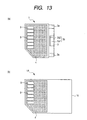
- FIGs. 13(a) and 13(b) are views for explaining such an assembling method, wherein Fig. 13 (a) is an overall plan view of the memory card 1 and Fig. 13 (b) is an overall plan view when the base substrate 4 of the memory card 1 is used in a state that the base substrate 4 is incorporated into the full-size memory card.
- a net-like hatching portion indicates a plane of the base substrate 4.
- the base substrate 4 (the base substrate 4 in the state that chips 5a and the like are mounted thereon) which is used for assembling the half-size memory card 1 is directly used as a full-size memory card 1A. That is, portions of the memory cards 1, 1A which differ in a planar size are shared in common.
- the reduction of the manufacturing cost of the base substrate 4 is effective to reduce the manufacturing cost of the memory card 1.
- these base substrates 4 require separate manufacturing steps, separate manufacturing devices and separate personnel and the like respectively. This incurs the increase of the manufacturing cost of the base substrates 4 so that the manufacturing cost of the memory card is increased.
- the base substrate 4 having a planar area which is equal to or less than one half of a planar area of the cap 16 is mounted on the full-size memory card 1A.
- Fig. 14 is a perspective view of a semiconductor device and an auxiliary piece of another embodiment of the present invention
- Figs. 15(a) and 15 (b) are perspective views showing appearances of a front surface side and rear surface side of the semiconductor device shown in Fig. 14
- Fig. 16 (a) is a plan view of the front surface side of the semiconductor device shown in Fig. 14
- Fig. 16 (b) is a side view of the semiconductor device shown in Fig. 16 (a)
- Fig. 16 (c) is a back view of the semiconductor device shown in Fig. 16 (a)
- Fig. 16 (d) is a plan view of the rear surface side of the semiconductor device shown in Fig. 16(a)
- Fig. 16 (a) is a plan view of the front surface side of the semiconductor device shown in Fig. 14
- Fig. 16 (b) is a side view of the semiconductor device shown in Fig. 16 (a)
- Fig. 16 (c) is a back view of the
- FIG. 17 (a) is a plan view of the front surfaces of the semiconductor device and auxiliary piece shown in Fig. 14, Fig. 17 (b) is a side view of Fig. 17 (a), and Fig. 17 (c) is a plan view of the rear surface of Fig. 17(a).
- This embodiment is equal to the above-mentioned embodiment 1 except for that the shape of connecting portions between the memory card 1 and the adapter 2 differs from that of the above-mentioned embodiment 1. That is, side faces of the adapter mounting portions 3a of the memory card 1 are formed coplanar with side faces of the memory card 1. That is, the side face portions of the adapter mounting portions 3a are not indented. Further, at portions of the recessed portions 2a of the adapter 2 which are fitted into these adapter mounting portions 3a, grooves 2a1 which allow the side face portions of the above-mentioned adapter mounting portions 3a to enter also to the side faces of the memory card 1 are partially formed.
- This embodiment having such a constitution can also obtain advantageous effects similar to those of the above-mentioned embodiment 1.
- Fig. 18 is a plan view of a rear surface side of a semiconductor device of still another embodiment of the present invention.
- a plurality of connection terminals 17 are regularly arranged in parallel along the longitudinal direction of the memory card 1.
- the connection terminals 17 are formed on the rear surface side of a base substrate 4 and are electrically connected with a memory circuit formed on the base substrate 4 through wiring on the base substrate 4.
- These connection terminals 17 constitute terminals for testing the above-mentioned memory circuit or for adding functions.
- Fig. 19 and Fig. 20 respectively show plan views of a front surface (part mounting surface) and a rear surface (external connection terminal forming surface) of the above-mentioned base substrate 4.
- the base substrate 4 is formed in a rectangular shape in plane and a chamfered portion (third chamfered portion) 4a which eliminates a corner is formed on one corresponding corner portion.
- the chamfered portion 4a is formed to conform with a chamfered portion for indexing which is formed at a distal end of a front face (mounting end) of the memory card.
- Fig. 21 and Fig. 22 are respectively plan views of a front surface and a rear surface of a cap (a first case body) 16 for the above-mentioned full-size memory card which the inventors have studied.
- the cap 16 is formed of resin or the like similar to that of the above-mentioned half-size cap 3.
- a chamfered portion (second chamfered portion) 16a for the above-mentioned indexing is formed at one front-face side corner portion of the memory card.
- This chamfered portion 16a is provided from a viewpoint of facilitating the recognition of the mounting direction of the full-size memory card.
- a groove 16b is formed in the rear surface of the cap 16 at the front face side of the memory card.
- This groove 16b is provided for mounting the base substrate 4 on the cap 16 and is formed such that the groove 16b occupies a region extending from the vicinity of the distal end of the cap 16 to a position slightly ahead of a longitudinally half position of the cap 16.
- the planar shape and dimensions of the groove 16b are formed such that the planar shape is equal to the planar shape of the base substrate 4 and the planar dimensions are slightly larger than the planar dimensions of the base substrate 4 so as to facilitate the accommodation and fitting of the base substrate 4.
- one corner portion thereof at the front face side of the cap is chamfered along the chamfered portion 16a of the cap 16 thus forming a chamfered portion 16b1.
- the long side which is formed at the longitudinally center side of the cap 16 crosses two short sides of the groove 16b at a right angle.
- a stepped portion 16e which has a thickness slightly larger than a thickness of the inner side of the groove 16b and is slightly smaller than a thickness of the outside of the groove 16b is formed.
- a plurality of pin traces 16f which are formed by cutting the stepped portion 16e indicate traces where ejector pins come into contact with when the cap 16 is removed from a mold after molding the cap 16 using the mold.
- card removing grooves 16c1, 16c2 are formed on the front surface and the back surface of the cap 16, in the vicinity of the back side.
- These card removing grooves 16c1, 16c2 are grooves which perform functions similar to the functions of card removing grooves 3c which have been explained in the previous embodiment 1 (See Fig. 1 and the like).
- a depth of the rear-surface side groove portion 16c2 is set greater than a depth of the front-surface side card removing groove 16c1. It may be possible to provide only either one of these card removing grooves 16c1, 16c2.
- a planar triangular mark 16d which indicates the insertion direction when the full-size memory card is mounted in the electronic device is formed on the surface of the cap 16, in the vicinity of the frontal face.
- a rectangular shallow indentation 16g having round corners in plane is formed on the most portion of the front surface of the cap 16.
- This indentation 16g is provided for laminating a seal or the like on which various information are written in such a manner that the classification of the memory cards is written or the like.
- Fig. 23 is a plan view of the rear surface of the full-size memory card 1A after the base substrate 4 shown in Fig. 19 and Fig. 20 is mounted in the groove 16b of the cap 16 shown in Fig. 21 and 22.
- the base substrate 4 is neatly mounted on the region which substantially covers one longitudinal half of the cap 16.
- the bending rupture strength test is performed as follows, for example. First of all, the memory card 1A is mounted on a test base in a state that the rear surface of the memory card 1A faces an upper surface of the test base. Here, support members are interposed between the rear surface of the memory card 1A and the upper surface of the test base at two positions in the vicinity of both longitudinal ends of the memory card 1A such that a gap of a given dimension is formed between the rear surface of the memory card 1A and the upper surface of the test base. In this state, by applying a load of a given quantity to the longitudinal center on the front surface of the memory card 1A so as to bend the memory card 1A, the rupture strength of the memory card 1A is evaluated.
- the inventors have originally found out that the memory card 1A shown in Fig. 23 suffers from following drawbacks. That is, the memory card 1A shown in Fig. 23 exhibits the lower bending rupture strength compared to the structure of a full-size memory card having a base substrate and a cap whose planar dimensions are approximately equal to those of the memory card 1A and hence, the base substrate 4 is peeled off at a boundary portion (gap portion) between the cap 16 and the base substrate 4 at the center of the rear surface of the memory card 1A, or cracks are generated on the cap 16 with portions where a long side which is formed at the longitudinally center side of the cap 16 out of long sides of the groove 16b formed in the cap 16 crosses two short sides of the groove 16b at right angle being as a starting point.
- the structure which can enhance the above-mentioned bending rupture strength is proposed.
- the structure has a following constitution.
- Fig. 24 and Fig. 25 are respectively plan views of a front surface (part mounting surface) and a rear surface (external connection terminal forming surface) of the base substrate 4 of the embodiment 4.
- the base substrate 4 of this embodiment 4 besides the above-mentioned chamfered portion 4a, corners at two corner corresponding portions are eliminated thus forming chamfered portions (first chamfered portions) 4b, 4c.
- These chamfered portions 4b, 4c exhibit a chamfered amount smaller than that of the chamfered portion 4a and are formed such that they have the same size and shape to form a left-and-right symmetry.
- the base substrate 4 of this embodiment 4 has the same constitutions as those explained in conjunction with the above-mentioned embodiment 1, Fig. 19 and Fig. 20 and the like.
- Fig. 26 and Fig. 27 are respectively plan views of a front surface and rear surface (base substrate mounting surface) of a cap 16 for a full-size memory card which mounts the base substrate 4 shown in Fig. 24 and Fig. 25 thereon.
- the cap 16 of this embodiment 4 differs in the shape of a groove (first groove) 16b which mounts the base substrate 4 therein from the previously-mentioned cap 16. Except for the above constitution, the cap 16 of this embodiment 4 has the same constitution as that of the cap 16 explained in conjunction with the above-mentioned embodiment 1, Fig. 21 and Fig. 22. That is, in this embodiment 4, with respect to the planar shape and dimensions of the groove 16b, to enable the neat fitting of the base substrate 4 shown in Fig.
- the groove 16b has the same planar shape as the base substrate 4 and has the planar dimensions which are slightly larger than those of the base substrate 4. Accordingly, with respect to long sides of the groove 16b, the long side 16b2 which is formed at the longitudinally center side of the cap 16 does not cross two short sides 16b3, 16b3 of the groove 16b at a right angle and the portions where the long sides 16b2 and the short sides 16b3 originally cross each other have corners thereof eliminated so that chamfered portions (first chamfered portions) 16b4, 16b5 are formed.
- the groove 16b is configured such that portions between the long side 16b2 and the short sides 16b3 gradually change crossing angles by way of the chamfered portions 16b4, 16b5 which intercect the long sizes 16b2 and the short sides 16b3 obliquely.
- the groove 16b is configured such that at two corner portions which are originally formed at the longitudinally center side of the cap 16, reinforcing portions 16h1, 16h2 having a right-angled isosceles triangular shape are arranged in a state that right-angular portions are aligned with two corner portions.
- These chamfered portions 16b4, 16b5 exhibit a chamfered amount smaller than that of the chamfered portion 16a and have the same size and shape to form a right-and-left symmetry each other.
- Fig. 28 is a plan view of the rear surface of the full-size memory card 1A after the base substrate 4 shown in Fig. 24 and Fig. 25 is mounted on the cap 16 shown in Fig. 26 and Fig. 27, and Fig. 29 indicates a cross-sectional view taken along a line A1-A1 in Fig. 28.
- the base substrate 4 is mounted in the inside of the groove 16b such that the front surface of the base substrate 4 is directed to the groove 16b side formed on the rear surface of the cap 16 and the chamfered portions 4b, 4c of the base substrate 4 respectively face the chamfered portions 16b4, 16b5 of the groove 16b.
- the base substrate 4 is supported in a state that the outer peripheral portion of the front surface thereof is brought into contact with the stepped portion 16e in the inside of the groove 16b of the cap 16.
- the length of contact between the base substrate 4 and the groove 16b can be set longer than the length of contact in the case illustrated in Fig. 23 and hence, the connecting strength between the base substrate 4 and the cap 16 can be enhanced.
- the right-angled portions which are liable to be subjected to stress concentration can be eliminated by providing the chamfered portions 4b, 4c to the base substrate 4 and by providing the chamfered portions 16b4, 16b5 to the groove 16b, it is possible to disperse the stress. Accordingly, in performing the bending rupture strength test, it is possible to prevent or suppress the peeling off of the base substrate 4 and it is also possible to suppress or prevent the occurrence of cracks on the cap 16.
- the above-mentioned structure which can enhance the bending rupture strength requires no additional other new members and is a simple structure obtained by only chamfering the corner portions of the base substrate 4 and the corner portions of the groove 16b of the cap 16 whereby the structure can be formed easily. Accordingly, the productivity is not damaged so that this embodiment can provide the highly reliable full-size memory card 1A.
- the full-size memory card 1A of this embodiment 4 is an effective structure also in an electrostatic rupture test.
- this electrostatic rupture test in a state that the memory card 1A is mounted on a test device, static electricity is applied to the memory card 1A from a back-face side.
- the base substrate is formed such that the base substrate extends to a position close to the back-face side of the memory card and hence, the distance of a conductive path from the back-face side of the memory card to the chip at the frontal side is short.
- the memory card 1A of this embodiment 4 is formed of the insulating cap 16 which extends from the back face thereof to the longitudinally approximately half position and hence, the distance of a conductive path from the back-face side thereof to the frontal face side chip is long whereby the full-size memory card 1A exhibits the structure which is difficult to be ruptured by the electrostatic rupture test.
- the structure having the planar dimensions of the base substrate set to approximately one half of the planar dimensions of the cap 16 can reduce the area of the base substrate 4 and the volume of the sealing resin 11 compared to the structure in which the base substrate and the full-size cap substantially have the same planar dimensions. Accordingly, it is possible to make the full-size memory card 1A light-weighted. Particularly, since the memory card 1A of the embodiment 4 has, as mentioned above, the corner portions of the base substrate 4 chamfered, the reduction of weight can be enhanced. Accordingly, the portability of the full-size memory card 1A can be enhanced.
- Fig. 30 to Fig. 32 are explanatory views showing the result of bending rupture strength test of the memory card 1A shown in Fig. 23.
- the bending rupture strength is dropped sharply and in a rectangular shape at a boundary portion (positions b3, b4) between the base substrate 4 and the cap 16 which is disposed at the approximately longitudinal center of the cap 16.
- symbols b1 to b4 are given to indicate positions for facilitating the understanding of the positional relationship between them in Fig. 30 to Fig. 32.
- Fig. 33 to Fig. 35 are explanatory views showing the result of bending rupture strength test of the memory card 1A shown in Fig. 28 and the like of this embodiment 4.
- the drop of the bending rupture strength at a boundary portion (positions b5, b6, b4) between the base substrate 4 and the cap 16 which is disposed at the approximately longitudinal center of the cap 16 is made relatively gentle and the minimum value is higher than the minimum value in the case of Fig. 31 and Fig. 32. That is, this embodiment 4 can enhance the bending rupture strength of the full-size memory card 1A.
- Fig. 36 is a plan view of the rear surface of the cap 16 of this embodiment 4.
- the length in the lateral direction of the groove 16d (that is, substantially the dimension in the lateral direction of the base substrate 4)
- X1 is set smaller than one half of the total length X2 in the longitudinal direction of the cap 16 (X1 ⁇ X2/2).
- This setting is made so as to enable the common use of the base substrate 4 in both of the full-size mode and the half-size mode. That is, when the width X1 is set equal to or longer than one half of the total length X2, the base substrate cannot be used in the half-size memory card 1 which has been explained in conjunction with the above-mentioned embodiment 1.
- the length X1 is approximately 14.5 mm, for example, and the total length X2 is approximately 32 mm, for example.
- the lengths X3, Y1 are approximately 2 mm, for example.
- the length L2 of the chamfered portion 16a is set longer than the lengths X3, Y1 (L2 > X3, Y1). This is because when the lengths X3, Y1 are set excessively large, the area of the base substrate 4 is made excessively small and hence, the chip cannot be mounted on the base substrate 4.
- the length L2 is set to 5.66 mm, for example.
- these lengths X3, Y1 are set larger than the thicknesses d8, d9, d10 (X3, Y1 > d8, d9, d10). This is because when the lengths X3, Y1 are set smaller than the thicknesses d8 to d10, a chamfered amount becomes excessively small so that it is difficult to sufficiently obtain the above-mentioned bending rupture strength.
- the thickness d8 is approximately 1 mm, for example, and the thicknesses d9, d10 are approximately 0.6 mm, for example.
- Fig. 37 is an enlarged cross-sectional view of an essential part of the memory card 1A of this embodiment 4.
- the total thickness of the memory card 1A corresponds to the thickness d11 of the cap 16.
- This thickness d11 is equal to or more than the thickness of d12 (d11 ⁇ d12).
- the thickness d12 is a thickness from the front surface of the cap 16 to the rear surface of the base substrate 4. The reason that the dimension is set in the above-mentioned manner is that when the thickness d12 becomes greater than the thickness d11, the memory card 1A cannot conform with the Standard of the memory card.
- the depth d13 indicates a depth of the groove 16b.
- the thickness d11 is approximately 1.4 mm, for example.
- the thickness d12 is equal to or less than 1.4 mm, for example.
- the depth d13 is approximately 1.04 mm, for example, and the thickness d14 is approximately 0.28 mm, for example.
- Fig. 38 is a cross-sectional view of the mold 15.
- the structure of the mold 15 is substantially equal to that which has been explained in conjunction with Fig. 11 and Fig. 12 (a), (c) of the above-mentioned embodiment 1.
- the difference lies in that the longitudinal length of the cavity 15c is set longer than the longitudinal length of the cavity explained in conjunction with Fig. 15. That is, the length of the portion extending from the approximately longitudinal center of the cavity 15c to a portion where the back face portion of the cap 16 is formed is set longer than the length of the corresponding portion shown in Fig. 11 and Fig. 12.
- Fig. 39 and Fig. 40 are plan views of the front surface (part mounting surface) of the base substrate 4 in this embodiment 4.
- one chip 5a for memory and one chip 5b for controller are mounted on the front surface of the base substrate 4. These chips 5a, 5b are arranged in parallel along the longitudinal direction of the base substrate 4 (that is, the direction along which a plurality of external connection terminals 9 (see Fig. 25 and Fig. 28) are arranged).
- the relatively large chip 5a for memory is arranged at a position apart from the chamfered portion 4a at the index side.
- the relatively small chip 5b for controller is arranged at a side close to the chamfered portion 4a at the index side. Due to such an arrangement, it is possible to realize a memory card of large capacity having a compact configuration.
- a memory circuit of a memory capacity of 16M, 32 bytes, for example is formed.
- the chip 5a for memory has a shape closer to square than the chip 5b for controller.
- the length L3 of one side of the chip 5a for memory is set greater than the length L4 of one side which extends in the longitudinal direction of the chip 5b for controller.
- a plurality of bonding pads 20a are arranged along this one side.
- the chip 5a for memory is mounted such that one side on which a plurality of bonding pads 20a are arranged is arranged at longitudinally center side of the base substrate 4, that is, at the side of the chip 5b for controller. These bonding pads 20a are electrically connected with wiring on the front surface of the base substrate 4 through bonding wires 6.
- a plurality of bonding pads 20b are arranged along these long sides.
- the chip 5b for controller is mounted on the front surface of the base substrate 4 such that the long sides thereof are arranged substantially parallel to one side along which a plurality of bonding pads 20a of the chip 5a for memory are arranged.
- These bonding pads 20b are electrically connected to wiring on the front surface of the base substrate 4 through the bonding wires 6.
- Such an arrangement of the chips 5a, 5b is also applicable to the above-mentioned embodiments 1 to 3.
- a metal layer 21 formed of gold plating or the like is formed on the front surface of the base substrate 4 at a longitudinal distal end side (at a side where the chamfered portion 4a is formed).
- the metal layer 21 constitutes a portion where a gate of a mold is arranged at the time of sealing the chips 5a, 5b. That is, in forming the sealing resin 11 (See Fig. 29 and the like), resin is made to flow toward the region where the chip 5a for memory is arranged through the region where the chip 5b for controller is arranged from the metal layer 21 side.
- Fig. 42 to Fig.46 are plan views of the front surface of the base substrate 4 during the assembling steps.
- a base substrate forming body 22 shown in Fig. 42 is prepared.
- a plurality of base substrates 4 are already connected to a frame body 22a of the base substrate forming body 22 by way of minute connecting portions 22b which are connected to two short-side centers of respective base substrates 4.
- the frame body 22a, the connecting portions 22b and the base substrates 4 are integrally formed.
- the chamfered portions 4b, 4c of the base substrate 4 are already formed.
- the chip 5a, 5b are mounted on the front surface of each base substrate 4 of the base substrate forming body 22 (step 100 in Fig. 41).
- the relatively large chip 5a for memory is mounted at a position apart from the chamfered portion 4a and the relatively small chip 5b for controller is mounted at a position close to the chamfered portion 4a.
- the plasma cleaning treatment is applied, for example (step 101 of Fig. 41).
- the main purpose of this step lies in that by cleaning the front surfaces of the gold plating layer which is thinly formed, the favorable connection state of the wires and metal plating layer is achieved in a bonding wire step which follows this step.
- each base substrate 4 the bonding pads 20a, 20b of the chips 5a, 5b are electrically connected to the wiring and the electrodes of the base substrate 4 through the bonding wires 6 (step 102 in Fig. 41).
- the chips 5a, 5b and the bonding wires 6 and the like are sealed using a transfer mold (step 103 in Fig. 41).
- the above-mentioned cleaning treatment may be applied to the base substrate 4 from a viewpoint of enhancement of the adhesive property of the sealing resin 11.
- the connecting portions 22b are cut so that the base substrates 4 are separated from the base substrate forming body 22 (step 104 in Fig. 41). In this manner, the base substrates 4 are formed.
- the above-mentioned base substrate 4 is mounted in the inside of the groove 16 of the cap 16 shown in Fig. 26 and Fig. 27 and is fixed thereto using an adhesive agent or the like (step 105A in Fig. 41).
- the base substrate 4 is mounted in the inside of the groove formed on the rear surface of the cap 3 which is explained in conjunction with Fig. 1 to Fig. 5 and the like of the previously mentioned embodiment 1 (the planar shape of such a groove being formed in the shape explained in conjunction with Fig. 27 to Fig. 29) and is fixed thereto by an adhesive agent or the like (step 105B in Fig. 41).
- two types of memory cards 1, 1A of full size and half size can be manufactured using one base substrate 4. That is, the manufacturing steps and members for the full-size and half-size memory cards 1, 1A can be partially used in common and hence, the manufacturing steps can be simplified and the manufacturing time is shortened and the manufacturing cost can be reduced compared to a case in which the memory cards 1, 1A are separately manufactured.
- Fig. 47 is a plan view of a rear surface in the full-size memory card 1A of this embodiment 5 and Fig. 48 is an enlarged plan view of a region Z1 in Fig. 47.
- minute indentations and projections 4d having a rectangular shape are formed in the vicinity of both corner portions positioned at the longitudinal center side of the full-size cap 16, while minute indentations and projections 16b7 having a rectangular shape are also formed in the vicinity of corner portions of the groove 16b of the cap 16 correspondingly such that these indentations and projections 16b7 can be snuggly fitted into the minute indentations and projections of the base substrate 4.
- Fig. 49 is a plan view of a back surface of a full-size memory card 1A of this embodiment 6 and Fig. 50 is an enlarged plan view of a region Z2 in Fig. 49.
- this embodiment 6 in the same manner as the above-mentioned embodiment 5, in the vicinity of corner portions of the base substrate 4 and in the vicinity of corner portions of a groove 16b of a cap 16 corresponding to the base substrate 4, minute indentations and projections 4d, 16b7 are formed.
- the difference between this embodiment 6 and the above-mentioned embodiment 5 lies in that side faces of respective minute indentations and projections 4d, 16b7 are tapered.
- the fitting engagement between the minute indentations and projections 4d of the base substrate 4 and the minute indentations and projections 4d of the groove 16b of the cap 16 is facilitated compared to the case explained in conjunction with the above-mentioned embodiment 5.
- the other constitutions of this embodiment are equal to those which have been explained in conjunction with the above-mentioned embodiments 1 to 4.
- the above-mentioned indentations and projections 4d, 16b7 may be formed on the long side 16b2 of the groove 16b and the long side of the base substrate 4 corresponding to the long side 16b2 of the groove 16b.
- Fig. 51 is a plan view of a back surface of a full-size memory card 1A of this embodiment 7.
- minute indentations and projections 4d in a serrated shape are formed, while minute indentations and projections 16b7 having a serrated shape are formed along a long side and short sides of a groove 16b of a cap 16 corresponding to the minute indentations and projections 4d such that the minute indentations and projections 4d, 16b7 can be snuggly fitted into each other.
- Fig. 52 and Fig. 53 respectively show plan views of a front surface and a rear surface of the half-size memory card 1 of this embodiment 8.
- a corner of one corner portion is eliminated thus forming the above-mentioned chamfered portion 3e at the index side.
- This chamfered portion 3e is provided from a viewpoint of facilitating the recognition of the mounting direction of the memory card 1 and the like.
- a mark 3d2 having an arrow shape which extends from a back face to the frontal face of the memory card 1 is formed.
- This mark 3d2 indicates the inserting direction when the memory card 1 is inserted into the above-mentioned electronic device.
- the memory card 1 is inserted into the electronic device using a distal end thereof in the lateral direction as the frontal face.
- the relatively large mark 3d2 is displayed on the memory card 1.
- a shallow groove 3f having a planar quadrangular shape is formed on the front surface of the cap 3 in a region apart from the chamfered portion 3e. This shallow groove 3f constitutes a region to which a seal which describes the content of recorded data of the memory card 1 or the like is laminated.
- a groove (second groove) 3g having a planar shape equal to that of the base substrate 4 and a planar dimensions which are slightly larger than the base substrate 4 is formed to enable the neat fitting of the base substrate 4 shown in Fig. 24 and Fig. 25 into the groove 3g (second groove).
- a long side 3g1 at a side in the vicinity of the back-face of the memory card 1 and two lateral sides 3g2, 3g2 of the groove 3g do not cross each other at a right angle and the portions where the long side 3g1 and the short sides 3g2, 3g2 originally cross each other have corners thereof eliminated so that the chamfered portions (first chamfered portions) 3g3, 3g4 are formed.
- the structure (including the chamfered portions 3g3, 3g4) of this groove 3g is equal to the structure of the groove 16b of the full-size cap 16 which has been explained in the above-mentioned embodiment 4.
- the base substrate 4 is applicable to both of the full-size memory card and the half size memory card. Further, the mounting state of the base substrate 4 on the groove 3g is equal to the corresponding mounting state which is explained in conjunction with the above-mentioned embodiment 4. Further, the above-mentioned groove portion 3b2 formed on the rear surface of the cap 3 also functions as a catching or hooking groove when the memory card 1 is removed from the electronic device.
- Fig. 54 illustrates a case in which the number of external connection terminals in the memory card 1 of this embodiment 9 is registered with the number of external connection terminals of a SD card (Panasonic, Toshiba limited, Sun Disk Inc.). On a rear surface of the memory card 1 (rear surface of the base substrate 4), nine pieces of external connection terminals 9 in total are arranged. Further, Fig. 55 illustrates a case in which the number of external connection terminals 4 in the memory card 1 of this embodiment 9 is registered with the number of external connection terminals of an IC card. On the rear surface of the memory card 1 (rear surface of the base substrate 4 ) , thirteen pieces of external connection terminals 9 in total are arranged, wherein these external connection terminals 9 are arranged in two rows partially. In both cases, this embodiment 9 can cope with the change of the Standard of memory without giving rise to any problem.
- Fig. 56 is a cross-sectional view of a full-size memory card 1A of this embodiment 10 and Fig. 57 is an enlarged cross-sectional view of an essential part in Fig. 56.
- an eaves portion 16i is integrally formed on a long side 16b2 of a groove 16b of a cap 16.
- the eaves portion 16i may be extended along the long side 16b2 or may be scattered at portions of the long side 16b2.
- a recessed portion 16j is formed on a side face at the long side 16b2 of the groove 16b.
- this embodiment 10 provides a structure which can firmly fix the base substrate 4.
- the portion of the back-face side of the base substrate 4 is made thin by half etching. Due to such a structure, it is possible to enhance the above-mentioned bending rupture strength so that the peeling-off of the base substrate 4 and the rupture of the cap 16 can be suppressed or prevented.
- the structure of this embodiment 10 it may be unnecessary to provide chamfered portions 16b4, 16b5 to the groove 16b.
- the eaves portions 16i may be formed at the chamfered portions 16b4, 16b5.
- the shape and the number of supporting portions of the adapter are not limited to those of the above-mentioned embodiments and various modifications can be made.
- the chips can adopt a connection method which uses bump electrodes besides the connection based on the wire bonding method.
- the present invention made by the inventors has been explained mainly with respect to the case in which the invention is applied to the memory card incorporating a flash memory (EEPROM) which constitutes the technical field of the background of this invention heretofore, the present invention is not limited to such a memory card and is applicable to a memory card incorporating other memory circuit such as SRAM (Static Random Access Memory), FRAM (Ferroelectric Random Access Memory) or MRAM (Magnetic Random Access Memory). Further, the present invention is also applicable to an IC (Integrated Circuit) card having no memory circuit.
- the mounting portion having a projecting cross section on which the recessed portion of the metal-made auxiliary piece for increasing the planar dimension of the case body is fitted to the portion of the case body which incorporates the semiconductor chip therein, the versatility of the semiconductor device can be enhanced.
- the bending rupture strength of the semiconductor device can be enhanced.
- the present invention is applicable to the semiconductor device and the manufacturing method thereof.
Priority Applications (1)
| Application Number | Priority Date | Filing Date | Title |
|---|---|---|---|
| EP07003853A EP1788512A1 (fr) | 2001-04-02 | 2001-12-28 | Dispositif sémi-conducteur et procédé pour sa fabrication |
Applications Claiming Priority (3)
| Application Number | Priority Date | Filing Date | Title |
|---|---|---|---|
| JP2001103535 | 2001-04-02 | ||
| JP2001103535 | 2001-04-02 | ||
| PCT/JP2001/011640 WO2002082364A1 (fr) | 2001-04-02 | 2001-12-28 | Dispositif semi-conducteur et son procédé de production |
Related Child Applications (1)
| Application Number | Title | Priority Date | Filing Date |
|---|---|---|---|
| EP07003853A Division EP1788512A1 (fr) | 2001-04-02 | 2001-12-28 | Dispositif sémi-conducteur et procédé pour sa fabrication |
Publications (3)
| Publication Number | Publication Date |
|---|---|
| EP1376452A1 true EP1376452A1 (fr) | 2004-01-02 |
| EP1376452A4 EP1376452A4 (fr) | 2005-04-13 |
| EP1376452B1 EP1376452B1 (fr) | 2007-04-25 |
Family
ID=18956580
Family Applications (2)
| Application Number | Title | Priority Date | Filing Date |
|---|---|---|---|
| EP07003853A Withdrawn EP1788512A1 (fr) | 2001-04-02 | 2001-12-28 | Dispositif sémi-conducteur et procédé pour sa fabrication |
| EP01274083A Expired - Lifetime EP1376452B1 (fr) | 2001-04-02 | 2001-12-28 | Carte multimedia et son procede de production |
Family Applications Before (1)
| Application Number | Title | Priority Date | Filing Date |
|---|---|---|---|
| EP07003853A Withdrawn EP1788512A1 (fr) | 2001-04-02 | 2001-12-28 | Dispositif sémi-conducteur et procédé pour sa fabrication |
Country Status (9)
| Country | Link |
|---|---|
| US (8) | US6858925B2 (fr) |
| EP (2) | EP1788512A1 (fr) |
| JP (2) | JP3943502B2 (fr) |
| KR (1) | KR100551658B1 (fr) |
| CN (5) | CN100501767C (fr) |
| AT (1) | ATE360859T1 (fr) |
| DE (1) | DE60128151T2 (fr) |
| TW (1) | TWI234273B (fr) |
| WO (1) | WO2002082364A1 (fr) |
Families Citing this family (70)
| Publication number | Priority date | Publication date | Assignee | Title |
|---|---|---|---|---|
| JP3822768B2 (ja) * | 1999-12-03 | 2006-09-20 | 株式会社ルネサステクノロジ | Icカードの製造方法 |
| WO2002082364A1 (fr) * | 2001-04-02 | 2002-10-17 | Hitachi, Ltd. | Dispositif semi-conducteur et son procédé de production |
| JP3850812B2 (ja) * | 2003-05-23 | 2006-11-29 | 三和電気工業株式会社 | メモリカード用アダプタ |
| JP2003258033A (ja) * | 2002-03-06 | 2003-09-12 | Seiko Epson Corp | 電子デバイス及びその製造方法並びに電子機器 |
| JP2006509277A (ja) * | 2002-11-18 | 2006-03-16 | ストーカード・インコーポレーテッド | 大容量記憶ボリュームを有する安全なトランザクション・カード |
| CN1287455C (zh) * | 2002-11-29 | 2006-11-29 | 株式会社东芝 | 半导体集成电路装置及使用它的电子卡 |
| CN1311398C (zh) * | 2003-06-04 | 2007-04-18 | 三和电气工业株式会社 | 存储器卡用适配器 |
| AU2003304308A1 (en) | 2003-07-03 | 2005-01-21 | Renesas Technology Corp. | Multi-function card device |
| JP4347018B2 (ja) * | 2003-10-24 | 2009-10-21 | モレックス インコーポレイテド | メモリーカード用互換装置およびメモリーカードモジュール |
| US20050155787A1 (en) * | 2004-01-20 | 2005-07-21 | Pierre Liu | Transparent small memory card |
| JP4651332B2 (ja) * | 2004-04-26 | 2011-03-16 | ルネサスエレクトロニクス株式会社 | メモリカード |
| TWI257583B (en) * | 2004-07-28 | 2006-07-01 | C One Technology Corp | Expandable reduced-size memory card and corresponding extended memory card |
| KR100599341B1 (ko) | 2004-07-30 | 2006-08-14 | (주)테라빛 | 실장효율이 높은 메모리 카드를 제조하는 방법 |
| US20060027906A1 (en) * | 2004-08-03 | 2006-02-09 | Sheng-Chih Hsu | Exclusive memory structure applicable for multi media card and secure digital card |
| US7055751B2 (en) * | 2004-08-09 | 2006-06-06 | Chong-Ia Precision Industry Co. Ltd. | Extension piece for length-reduced memory card |
| FR2875625B1 (fr) * | 2004-09-20 | 2006-12-08 | Gemplus Sa | Support adaptateur de carte a puce deverrouillable et procede de fabrication du support |
| JP2006092094A (ja) * | 2004-09-22 | 2006-04-06 | Sony Corp | メモリカード |
| JP4506389B2 (ja) * | 2004-09-30 | 2010-07-21 | ソニー株式会社 | カード型周辺装置 |
| JP2006128459A (ja) * | 2004-10-29 | 2006-05-18 | Renesas Technology Corp | 半導体装置およびその製造方法 |
| KR100574996B1 (ko) * | 2004-11-25 | 2006-05-02 | 삼성전자주식회사 | 반도체 패키지 및 이를 이용한 메모리 카드, 및 이의제조에 이용되는 몰드 |
| JP2006155521A (ja) * | 2004-12-01 | 2006-06-15 | Oki Electric Ind Co Ltd | Icカード |
| CN1864979A (zh) * | 2005-05-10 | 2006-11-22 | 刘钦栋 | 记忆卡封装方法 |
| TWI249772B (en) * | 2005-06-07 | 2006-02-21 | Siliconware Precision Industries Co Ltd | Semiconductor device for accommodating large chip, fabrication method thereof, and carrier used in the semiconductor device |
| US7345848B2 (en) * | 2005-11-14 | 2008-03-18 | Sun-Light Electronic Technologies Inc. | Packaging structure of mini SD memory card |
| JP4815212B2 (ja) * | 2005-12-26 | 2011-11-16 | 株式会社ディスコ | メモリーカードの製造方法 |
| JP2007179176A (ja) * | 2005-12-27 | 2007-07-12 | Disco Abrasive Syst Ltd | 配線基板及びメモリーカードの製造方法 |
| CN101405752B (zh) * | 2006-04-21 | 2012-05-09 | 松下电器产业株式会社 | 存储卡 |
| KR100828956B1 (ko) * | 2006-06-27 | 2008-05-13 | 하나 마이크론(주) | Usb 메모리 패키지 및 그 제조 방법 |
| WO2008017063A2 (fr) * | 2006-08-03 | 2008-02-07 | Inphase Technologies, Inc. | SCANNER MINIATURE À ACTIONNEUR UNIQUE POUR MULTIPLEXAGE ANGULAIRE AVEC circularisation ET CAPACITÉ DE CORRECTION DU TANGAGE |
| US7705475B2 (en) * | 2006-08-03 | 2010-04-27 | Stats Chippac Ltd. | Integrated circuit package system |
| WO2008027882A2 (fr) | 2006-08-28 | 2008-03-06 | Inphase Technologies, Inc. | Lentille tolérant un décalage optimisée pour des systèmes holographiques à conjugaison de phase |
| US7738153B2 (en) * | 2006-09-29 | 2010-06-15 | Inphase Technologies, Inc. | Magnetic field position feedback for holographic storage scanner |
| US7950586B2 (en) * | 2006-10-26 | 2011-05-31 | Sandisk Il Ltd. | SIM card handle |
| US20080102895A1 (en) * | 2006-10-26 | 2008-05-01 | Sandisk Il Ltd. | Method Of Extracting A Smart Card From A Smart Card Socket |
| US20080239428A1 (en) * | 2007-04-02 | 2008-10-02 | Inphase Technologies, Inc. | Non-ft plane angular filters |
| EP2183776A1 (fr) * | 2007-07-10 | 2010-05-12 | InPhase Technologies, Inc. | Procédé pour permettre la rétrocompatibilité de support holographique avec un connecteur de carte multimédia à double usage |
| US8141782B2 (en) * | 2007-07-10 | 2012-03-27 | Inphase Technologies, Inc. | Dual-use media card connector for backwards compatible holographic media card |
| US7872483B2 (en) | 2007-12-12 | 2011-01-18 | Samsung Electronics Co., Ltd. | Circuit board having bypass pad |
| TWI358911B (en) * | 2007-12-24 | 2012-02-21 | Ind Tech Res Inst | Receiver with discrete-time down-conversion and fi |
| TWI347097B (en) * | 2007-12-31 | 2011-08-11 | Ind Tech Res Inst | Circuit with programmable signal bandwidth and method thereof |
| KR20100041514A (ko) * | 2008-10-14 | 2010-04-22 | 삼성전자주식회사 | 검사시간을 단축할 수 있는 솔리드 스테이트 드라이브 장치및 그 검사방법 |
| KR20100041515A (ko) * | 2008-10-14 | 2010-04-22 | 삼성전자주식회사 | 제거 가능한 보조 검사단자를 갖는 솔리드 스테이트 드라이브의 검사방법 |
| JP2011048756A (ja) | 2009-08-28 | 2011-03-10 | Toshiba Corp | メモリモジュール |
| US8469280B2 (en) | 2009-10-22 | 2013-06-25 | Intellipaper, Llc | Programming devices and programming methods |
| US8469271B2 (en) | 2009-10-22 | 2013-06-25 | Intellipaper, Llc | Electronic storage devices, programming methods, and device manufacturing methods |
| US8523071B2 (en) | 2009-10-22 | 2013-09-03 | Intellipaper, Llc | Electronic assemblies and methods of forming electronic assemblies |
| WO2011127183A2 (fr) | 2010-04-07 | 2011-10-13 | Intellipaper , Llc | Procédés de programmation de mémoire et dispositifs de programmation de mémoire |
| USD667830S1 (en) * | 2011-11-29 | 2012-09-25 | Samsung Electronics Co., Ltd. | SD memory card |
| USD669479S1 (en) * | 2012-01-13 | 2012-10-23 | Research In Motion Limited | Device smart card |
| USD669478S1 (en) * | 2012-01-13 | 2012-10-23 | Research In Motion Limited | Device smart card |
| US20130258576A1 (en) * | 2012-03-29 | 2013-10-03 | Gadi Ben-Gad | Memory Card |
| US9136621B1 (en) * | 2012-08-14 | 2015-09-15 | Ciena Corporation | Guides and tab arrangement to retain a card having an edge connector and method of use |
| KR101893032B1 (ko) | 2012-11-08 | 2018-10-04 | 삼성전자주식회사 | 메모리 카드 어댑터 |
| US9722653B2 (en) | 2012-11-08 | 2017-08-01 | Samsung Electronics Co., Ltd. | Memory card adapter |
| USD707682S1 (en) * | 2012-12-05 | 2014-06-24 | Logomotion, S.R.O. | Memory card |
| JP5942078B2 (ja) * | 2013-01-28 | 2016-06-29 | 本多通信工業株式会社 | カード用コネクタ |
| US9647997B2 (en) | 2013-03-13 | 2017-05-09 | Nagrastar, Llc | USB interface for performing transport I/O |
| USD729808S1 (en) | 2013-03-13 | 2015-05-19 | Nagrastar Llc | Smart card interface |
| US9888283B2 (en) | 2013-03-13 | 2018-02-06 | Nagrastar Llc | Systems and methods for performing transport I/O |
| USD758372S1 (en) * | 2013-03-13 | 2016-06-07 | Nagrastar Llc | Smart card interface |
| USD759022S1 (en) | 2013-03-13 | 2016-06-14 | Nagrastar Llc | Smart card interface |
| EP2982225A4 (fr) * | 2013-04-05 | 2017-05-17 | PNY Technologies, Inc. | Carte mémoire de longueur réduite |
| USD734756S1 (en) * | 2014-04-04 | 2015-07-21 | Pny Technologies, Inc. | Reduced length memory card |
| USD732038S1 (en) * | 2014-05-04 | 2015-06-16 | Pierce Schiller | Memory card component |
| USD780763S1 (en) | 2015-03-20 | 2017-03-07 | Nagrastar Llc | Smart card interface |
| USD864968S1 (en) | 2015-04-30 | 2019-10-29 | Echostar Technologies L.L.C. | Smart card interface |
| KR102409892B1 (ko) | 2015-08-20 | 2022-06-15 | 삼성전자주식회사 | 메모리 카드 어댑터 및 메모리 장치 |
| US11093811B2 (en) | 2017-06-05 | 2021-08-17 | Kioxia Corporation | Memory card with multiple modes, and host device corresponding to the memory card |
| US11166363B2 (en) | 2019-01-11 | 2021-11-02 | Tactotek Oy | Electrical node, method for manufacturing electrical node and multilayer structure comprising electrical node |
| US11653463B2 (en) * | 2020-05-20 | 2023-05-16 | Western Digital Technologies, Inc. | Removable memory card with efficient card lock mechanism and pads layout |
Citations (14)
| Publication number | Priority date | Publication date | Assignee | Title |
|---|---|---|---|---|
| US4727246A (en) * | 1984-08-31 | 1988-02-23 | Casio Computer Co., Ltd. | IC card |
| EP0774727A2 (fr) * | 1995-11-17 | 1997-05-21 | Kabushiki Kaisha Toshiba | Lecteur/enregistreur de carte à puce |
| EP0817116A2 (fr) * | 1996-07-03 | 1998-01-07 | ODS R. Oldenbourg Datensysteme GmbH & Co. KG | Carte à puce ainsi que le procédé et la fabrication d'une carte à puce |
| EP0869452A1 (fr) * | 1997-04-02 | 1998-10-07 | ODS R. Oldenbourg Datensysteme GmbH & Co. KG | Mini carte à puce et méthode de production |
| US5820414A (en) * | 1995-12-19 | 1998-10-13 | Mitsubishi Denki Kabushiki Kaisha | IC card adaptor and construction of connecting portion between adaptor and IC card |
| US5936227A (en) * | 1996-02-23 | 1999-08-10 | Orga Kartensysteme Gmbh | Plastics card comprising a mini-smart-card which can be separated therefrom |
| US6076737A (en) * | 1995-04-13 | 2000-06-20 | Dai Nippon Printing Co., Ltd. | Apparatus and method of manufacturing an integrated circuit (IC) card with a protective IC module |
| US6112996A (en) * | 1996-06-03 | 2000-09-05 | Minolta Co., Ltd. | IC card and autonomous running and working robot having an IC card mounting apparatus |
| US6147861A (en) * | 1993-07-23 | 2000-11-14 | Kabushiki Kaisha Toshiba | External storage device unit |
| DE19922063A1 (de) * | 1999-05-14 | 2000-11-23 | Bosch Gmbh Robert | Adapterkarte und Kommunikationsvorrichtung |
| DE19929912A1 (de) * | 1999-06-29 | 2001-01-18 | Orga Kartensysteme Gmbh | Trägerelement für einen IC-Baustein |
| US6182159B1 (en) * | 1995-09-19 | 2001-01-30 | Ricoh Company, Ltd. | System for detachably connecting memory cards which provide memory specified by predetermined range of addresses registered in list and updating list independent of the I/O operation |
| EP1076317A2 (fr) * | 1999-08-10 | 2001-02-14 | Nokia Mobile Phones Ltd. | Adaptateur pour carte |
| US6193163B1 (en) * | 1998-08-31 | 2001-02-27 | The Standard Register Company | Smart card with replaceable chip |
Family Cites Families (56)
| Publication number | Priority date | Publication date | Assignee | Title |
|---|---|---|---|---|
| DE368082C (de) * | 1913-11-19 | 1923-02-20 | George Bloesy | Verfahren zur Herstellung von hydraulischen Kalken und Zementen aus den Rueckstaenden von Feuerungsanlagen aller Art |
| CA1204213A (fr) * | 1982-09-09 | 1986-05-06 | Masahiro Takeda | Carte a memoire protegee contre l'electricite statique |
| JPS62183396A (ja) | 1986-02-07 | 1987-08-11 | 株式会社日立製作所 | 外部記憶カ−ド |
| JPS636872U (fr) | 1986-06-27 | 1988-01-18 | ||
| JPS639586A (ja) * | 1986-06-30 | 1988-01-16 | 株式会社東芝 | メモリカ−ド |
| JPS63212595A (ja) | 1987-03-02 | 1988-09-05 | 三菱電機株式会社 | 半導体モジユ−ル製造用基板 |
| JPH01184192A (ja) | 1988-01-20 | 1989-07-21 | Matsushita Electric Ind Co Ltd | Icカード用モジュールの製造方法 |
| JPH0719859B2 (ja) | 1988-12-12 | 1995-03-06 | 松下電器産業株式会社 | Icカード用モジュールの製造方法 |
| JPH02158394A (ja) | 1988-12-13 | 1990-06-18 | Fujitsu Ltd | Icカード用半導体icデバイス |
| JPH02301155A (ja) | 1989-05-16 | 1990-12-13 | Citizen Watch Co Ltd | Icモジュールの固定方法 |
| JPH03114788A (ja) | 1989-09-29 | 1991-05-15 | Citizen Watch Co Ltd | Icカード構造 |
| JPH03158297A (ja) | 1989-11-15 | 1991-07-08 | Sharp Corp | Icカード |
| JP2560895B2 (ja) | 1990-07-25 | 1996-12-04 | 三菱電機株式会社 | Icカードの製造方法およびicカード |
| DE4105869C2 (de) | 1991-02-25 | 2000-05-18 | Edgar Schneider | IC-Karte und Verfahren zu ihrer Herstellung |
| JP2672924B2 (ja) * | 1992-07-30 | 1997-11-05 | 三菱電機株式会社 | 非接触icカードとその製造方法及びテスト方法 |
| US5341141A (en) * | 1993-03-09 | 1994-08-23 | Hughes Missile Systems Company | Three dimensional imaging radar |
| JPH06318390A (ja) | 1993-03-11 | 1994-11-15 | Toshiba Corp | Icメモリカード |
| JPH0668865U (ja) | 1993-03-11 | 1994-09-27 | セイコーエプソン株式会社 | Icカード |
| US5887145A (en) * | 1993-09-01 | 1999-03-23 | Sandisk Corporation | Removable mother/daughter peripheral card |
| US7137011B1 (en) * | 1993-09-01 | 2006-11-14 | Sandisk Corporation | Removable mother/daughter peripheral card |
| JPH07117385A (ja) | 1993-09-01 | 1995-05-09 | Toshiba Corp | 薄型icカードおよび薄型icカードの製造方法 |
| JPH07210645A (ja) * | 1994-01-24 | 1995-08-11 | Sony Corp | メモリカード |
| JPH07214957A (ja) * | 1994-01-31 | 1995-08-15 | Mitsubishi Electric Corp | Icカード |
| USD368082S (en) | 1994-05-07 | 1996-03-19 | Sony Corporation | Memory card |
| JP3256374B2 (ja) * | 1994-05-27 | 2002-02-12 | 本田技研工業株式会社 | マルチビーム・レーダ装置 |
| JP3660382B2 (ja) | 1995-02-03 | 2005-06-15 | 株式会社東芝 | 情報記憶装置およびそれに用いるコネクタ部 |
| US5663825A (en) * | 1995-06-07 | 1997-09-02 | Martin Marietta Corporation | Stabilized step/stare scanning device |
| JPH09286187A (ja) | 1996-04-22 | 1997-11-04 | Toppan Printing Co Ltd | Icカード、icカード製造用中間体およびicカードの製造方法 |
| JPH1095031A (ja) * | 1996-09-24 | 1998-04-14 | Dainippon Printing Co Ltd | 情報カードの成形金型及び成形方法並びに情報カード |
| KR100255108B1 (en) | 1997-06-18 | 2000-05-01 | Samsung Electronics Co Ltd | Chip card |
| JPH1131207A (ja) * | 1997-07-11 | 1999-02-02 | Toppan Printing Co Ltd | 非接触型icカードとその非常時読出方法 |
| US5987357A (en) * | 1997-07-30 | 1999-11-16 | Intermedics Inc. | Stackable microelectronic components with self-addressing scheme |
| JP2000011130A (ja) | 1998-03-26 | 2000-01-14 | Toshiba Corp | 記憶装置、カ―ド型記憶装置、および電子装置 |
| TW407364B (en) * | 1998-03-26 | 2000-10-01 | Toshiba Corp | Memory apparatus, card type memory apparatus, and electronic apparatus |
| US6040622A (en) | 1998-06-11 | 2000-03-21 | Sandisk Corporation | Semiconductor package using terminals formed on a conductive layer of a circuit board |
| US6279114B1 (en) * | 1998-11-04 | 2001-08-21 | Sandisk Corporation | Voltage negotiation in a single host multiple cards system |
| JP2000148953A (ja) * | 1998-11-16 | 2000-05-30 | Hitachi Ltd | メモリカード |
| JP3391375B2 (ja) * | 1999-03-02 | 2003-03-31 | 日本電気株式会社 | Icカードを備えた携帯電話機用バッテリ |
| FI107973B (fi) | 1999-03-11 | 2001-10-31 | Nokia Mobile Phones Ltd | Menetelmä ja välineet lisäkorttien käyttämiseksi matkaviestimessä |
| JP2000276573A (ja) * | 1999-03-23 | 2000-10-06 | Hitachi Ferrite Electronics Ltd | メモリーカード及びメモリーカードアダプタ |
| JP3590543B2 (ja) | 1999-04-09 | 2004-11-17 | 新日本製鐵株式会社 | 高炉への含鉄粉吹き込み方法 |
| JP2000305662A (ja) * | 1999-04-23 | 2000-11-02 | Jst Mfg Co Ltd | カード接続用アダプタ |
| JP2001043700A (ja) * | 1999-08-02 | 2001-02-16 | Fujitsu Ltd | 半導体記憶装置 |
| JP2001067303A (ja) * | 1999-08-24 | 2001-03-16 | Toshiba Corp | カード利用装置及び同装置におけるカード利用方法 |
| JP3822768B2 (ja) | 1999-12-03 | 2006-09-20 | 株式会社ルネサステクノロジ | Icカードの製造方法 |
| JP2001184475A (ja) * | 1999-12-27 | 2001-07-06 | Hitachi Ltd | メモリカード |
| JP3768761B2 (ja) | 2000-01-31 | 2006-04-19 | 株式会社日立製作所 | 半導体装置およびその製造方法 |
| KR100335717B1 (ko) | 2000-02-18 | 2002-05-08 | 윤종용 | 고용량 메모리 카드 |
| JP2001297307A (ja) * | 2000-04-12 | 2001-10-26 | Sony Corp | アダプタおよび電子カードモジュール |
| KR100335716B1 (ko) | 2000-05-23 | 2002-05-08 | 윤종용 | 메모리 카드 |
| US7107378B1 (en) * | 2000-09-01 | 2006-09-12 | Sandisk Corporation | Cooperative interconnection and operation of a non-volatile memory card and an input-output card |
| US6624005B1 (en) | 2000-09-06 | 2003-09-23 | Amkor Technology, Inc. | Semiconductor memory cards and method of making same |
| US6462273B1 (en) | 2001-03-16 | 2002-10-08 | Micron Technology, Inc. | Semiconductor card and method of fabrication |
| WO2002082364A1 (fr) * | 2001-04-02 | 2002-10-17 | Hitachi, Ltd. | Dispositif semi-conducteur et son procédé de production |
| US6774851B1 (en) * | 2001-09-28 | 2004-08-10 | Her Majesty In Right Of Canada, As Represented By The Minister Of Industry | Antenna with variable phase shift |
| WO2008057286A2 (fr) * | 2006-10-27 | 2008-05-15 | Clariant Technologies Corp. | Procédé et appareil pour imagerie à micro-ondes et ondes millimétriques |
-
2001
- 2001-12-28 WO PCT/JP2001/011640 patent/WO2002082364A1/fr active IP Right Grant
- 2001-12-28 KR KR1020027014021A patent/KR100551658B1/ko not_active IP Right Cessation
- 2001-12-28 CN CNB2006100818716A patent/CN100501767C/zh not_active Expired - Fee Related
- 2001-12-28 CN CNA2006100818701A patent/CN101004944A/zh active Pending
- 2001-12-28 JP JP2002580253A patent/JP3943502B2/ja not_active Expired - Fee Related
- 2001-12-28 EP EP07003853A patent/EP1788512A1/fr not_active Withdrawn
- 2001-12-28 DE DE60128151T patent/DE60128151T2/de not_active Expired - Lifetime
- 2001-12-28 EP EP01274083A patent/EP1376452B1/fr not_active Expired - Lifetime
- 2001-12-28 US US10/240,187 patent/US6858925B2/en not_active Expired - Lifetime
- 2001-12-28 CN CNB018083439A patent/CN1267996C/zh not_active Expired - Fee Related
- 2001-12-28 AT AT01274083T patent/ATE360859T1/de not_active IP Right Cessation
- 2001-12-28 CN CNB2006100818699A patent/CN100435170C/zh not_active Expired - Fee Related
- 2001-12-28 CN CNA2006100818720A patent/CN1866277A/zh active Pending
-
2002
- 2002-02-08 TW TW091102479A patent/TWI234273B/zh not_active IP Right Cessation
- 2002-10-10 US US10/267,784 patent/US7053471B2/en not_active Expired - Fee Related
-
2003
- 2003-02-12 US US10/364,345 patent/US20030117785A1/en not_active Abandoned
-
2005
- 2005-08-16 US US11/203,969 patent/US7233058B2/en not_active Expired - Fee Related
- 2005-08-16 US US11/204,047 patent/US7239011B2/en not_active Expired - Fee Related
-
2006
- 2006-05-10 US US11/431,074 patent/US7271475B2/en not_active Expired - Fee Related
- 2006-05-10 US US11/431,072 patent/US7294918B2/en not_active Expired - Fee Related
-
2009
- 2009-02-19 JP JP2009036042A patent/JP2009151815A/ja active Pending
- 2009-07-23 US US12/508,089 patent/US20090283885A1/en not_active Abandoned
Patent Citations (14)
| Publication number | Priority date | Publication date | Assignee | Title |
|---|---|---|---|---|
| US4727246A (en) * | 1984-08-31 | 1988-02-23 | Casio Computer Co., Ltd. | IC card |
| US6147861A (en) * | 1993-07-23 | 2000-11-14 | Kabushiki Kaisha Toshiba | External storage device unit |
| US6076737A (en) * | 1995-04-13 | 2000-06-20 | Dai Nippon Printing Co., Ltd. | Apparatus and method of manufacturing an integrated circuit (IC) card with a protective IC module |
| US6182159B1 (en) * | 1995-09-19 | 2001-01-30 | Ricoh Company, Ltd. | System for detachably connecting memory cards which provide memory specified by predetermined range of addresses registered in list and updating list independent of the I/O operation |
| EP0774727A2 (fr) * | 1995-11-17 | 1997-05-21 | Kabushiki Kaisha Toshiba | Lecteur/enregistreur de carte à puce |
| US5820414A (en) * | 1995-12-19 | 1998-10-13 | Mitsubishi Denki Kabushiki Kaisha | IC card adaptor and construction of connecting portion between adaptor and IC card |
| US5936227A (en) * | 1996-02-23 | 1999-08-10 | Orga Kartensysteme Gmbh | Plastics card comprising a mini-smart-card which can be separated therefrom |
| US6112996A (en) * | 1996-06-03 | 2000-09-05 | Minolta Co., Ltd. | IC card and autonomous running and working robot having an IC card mounting apparatus |
| EP0817116A2 (fr) * | 1996-07-03 | 1998-01-07 | ODS R. Oldenbourg Datensysteme GmbH & Co. KG | Carte à puce ainsi que le procédé et la fabrication d'une carte à puce |
| EP0869452A1 (fr) * | 1997-04-02 | 1998-10-07 | ODS R. Oldenbourg Datensysteme GmbH & Co. KG | Mini carte à puce et méthode de production |
| US6193163B1 (en) * | 1998-08-31 | 2001-02-27 | The Standard Register Company | Smart card with replaceable chip |
| DE19922063A1 (de) * | 1999-05-14 | 2000-11-23 | Bosch Gmbh Robert | Adapterkarte und Kommunikationsvorrichtung |
| DE19929912A1 (de) * | 1999-06-29 | 2001-01-18 | Orga Kartensysteme Gmbh | Trägerelement für einen IC-Baustein |
| EP1076317A2 (fr) * | 1999-08-10 | 2001-02-14 | Nokia Mobile Phones Ltd. | Adaptateur pour carte |
Non-Patent Citations (3)
| Title |
|---|
| MMCA TECHNICAL COMMITTEE: "THE MULTIMEDIA CARD system summary, based on system specification version 2.2" MULTIMEDIACARD STANDARD, VERSION 2.2, January 2000 (2000-01), XP002278380 * |
| PATENT ABSTRACTS OF JAPAN vol. 1995, no. 11, 26 December 1995 (1995-12-26) & JP 07 210645 A (SONY CORP), 11 August 1995 (1995-08-11) * |
| See also references of WO02082364A1 * |
Also Published As
Similar Documents
| Publication | Publication Date | Title |
|---|---|---|
| EP1376452A1 (fr) | Dispositif semi-conducteur et son procede de production | |
| JP2005122657A (ja) | Icカード | |
| JP3943571B2 (ja) | メモリカード | |
| JP2006302278A (ja) | メモリカード | |
| JP3803362B2 (ja) | メモリカード | |
| KR100551657B1 (ko) | 반도체 장치 및 그 제조 방법 | |
| JP2006236373A (ja) | メモリカード | |
| JPS6282094A (ja) | 磁気ストライプ付icカ−ド | |
| JPS6282093A (ja) | 磁気ストライプ付icカ−ド |
Legal Events
| Date | Code | Title | Description |
|---|---|---|---|
| PUAI | Public reference made under article 153(3) epc to a published international application that has entered the european phase |
Free format text: ORIGINAL CODE: 0009012 |
|
| 17P | Request for examination filed |
Effective date: 20021010 |
|
| AK | Designated contracting states |
Kind code of ref document: A1 Designated state(s): AT BE CH CY DE DK ES FI FR GB GR IE IT LI LU MC NL PT SE TR |
|
| AX | Request for extension of the european patent |
Extension state: AL LT LV MK RO SI |
|
| RIC1 | Information provided on ipc code assigned before grant |
Ipc: 7G 06K 19/00 B Ipc: 7G 06K 17/00 A Ipc: 7G 06K 19/077 B |
|
| A4 | Supplementary search report drawn up and despatched |
Effective date: 20050223 |
|
| GRAP | Despatch of communication of intention to grant a patent |
Free format text: ORIGINAL CODE: EPIDOSNIGR1 |
|
| RTI1 | Title (correction) |
Free format text: MULTI MEDIA CARD AND ITS MANUFACTURING METHOD |
|
| GRAS | Grant fee paid |
Free format text: ORIGINAL CODE: EPIDOSNIGR3 |
|
| GRAA | (expected) grant |
Free format text: ORIGINAL CODE: 0009210 |
|
| AK | Designated contracting states |
Kind code of ref document: B1 Designated state(s): AT BE CH CY DE DK ES FI FR GB GR IE IT LI LU MC NL PT SE TR |
|
| PG25 | Lapsed in a contracting state [announced via postgrant information from national office to epo] |
Ref country code: LI Free format text: LAPSE BECAUSE OF FAILURE TO SUBMIT A TRANSLATION OF THE DESCRIPTION OR TO PAY THE FEE WITHIN THE PRESCRIBED TIME-LIMIT Effective date: 20070425 Ref country code: CH Free format text: LAPSE BECAUSE OF FAILURE TO SUBMIT A TRANSLATION OF THE DESCRIPTION OR TO PAY THE FEE WITHIN THE PRESCRIBED TIME-LIMIT Effective date: 20070425 |
|
| REG | Reference to a national code |
Ref country code: GB Ref legal event code: FG4D |
|
| REG | Reference to a national code |
Ref country code: IE Ref legal event code: FG4D |
|
| REG | Reference to a national code |
Ref country code: CH Ref legal event code: EP |
|
| REF | Corresponds to: |
Ref document number: 60128151 Country of ref document: DE Date of ref document: 20070606 Kind code of ref document: P |
|
| REG | Reference to a national code |
Ref country code: SE Ref legal event code: TRGR |
|
| PG25 | Lapsed in a contracting state [announced via postgrant information from national office to epo] |
Ref country code: ES Free format text: LAPSE BECAUSE OF FAILURE TO SUBMIT A TRANSLATION OF THE DESCRIPTION OR TO PAY THE FEE WITHIN THE PRESCRIBED TIME-LIMIT Effective date: 20070805 |
|
| PG25 | Lapsed in a contracting state [announced via postgrant information from national office to epo] |
Ref country code: PT Free format text: LAPSE BECAUSE OF FAILURE TO SUBMIT A TRANSLATION OF THE DESCRIPTION OR TO PAY THE FEE WITHIN THE PRESCRIBED TIME-LIMIT Effective date: 20070925 |
|
| ET | Fr: translation filed | ||
| REG | Reference to a national code |
Ref country code: CH Ref legal event code: PL |
|
| PG25 | Lapsed in a contracting state [announced via postgrant information from national office to epo] |
Ref country code: AT Free format text: LAPSE BECAUSE OF FAILURE TO SUBMIT A TRANSLATION OF THE DESCRIPTION OR TO PAY THE FEE WITHIN THE PRESCRIBED TIME-LIMIT Effective date: 20070425 |
|
| PG25 | Lapsed in a contracting state [announced via postgrant information from national office to epo] |
Ref country code: BE Free format text: LAPSE BECAUSE OF FAILURE TO SUBMIT A TRANSLATION OF THE DESCRIPTION OR TO PAY THE FEE WITHIN THE PRESCRIBED TIME-LIMIT Effective date: 20070425 |
|
| PG25 | Lapsed in a contracting state [announced via postgrant information from national office to epo] |
Ref country code: DK Free format text: LAPSE BECAUSE OF FAILURE TO SUBMIT A TRANSLATION OF THE DESCRIPTION OR TO PAY THE FEE WITHIN THE PRESCRIBED TIME-LIMIT Effective date: 20070425 |
|
| PLBE | No opposition filed within time limit |
Free format text: ORIGINAL CODE: 0009261 |
|
| STAA | Information on the status of an ep patent application or granted ep patent |
Free format text: STATUS: NO OPPOSITION FILED WITHIN TIME LIMIT |
|
| 26N | No opposition filed |
Effective date: 20080128 |
|
| PG25 | Lapsed in a contracting state [announced via postgrant information from national office to epo] |
Ref country code: IT Free format text: LAPSE BECAUSE OF FAILURE TO SUBMIT A TRANSLATION OF THE DESCRIPTION OR TO PAY THE FEE WITHIN THE PRESCRIBED TIME-LIMIT Effective date: 20070425 Ref country code: GR Free format text: LAPSE BECAUSE OF FAILURE TO SUBMIT A TRANSLATION OF THE DESCRIPTION OR TO PAY THE FEE WITHIN THE PRESCRIBED TIME-LIMIT Effective date: 20070726 |
|
| PG25 | Lapsed in a contracting state [announced via postgrant information from national office to epo] |
Ref country code: MC Free format text: LAPSE BECAUSE OF NON-PAYMENT OF DUE FEES Effective date: 20071231 |
|
| PG25 | Lapsed in a contracting state [announced via postgrant information from national office to epo] |
Ref country code: IE Free format text: LAPSE BECAUSE OF NON-PAYMENT OF DUE FEES Effective date: 20071228 |
|
| PG25 | Lapsed in a contracting state [announced via postgrant information from national office to epo] |
Ref country code: CY Free format text: LAPSE BECAUSE OF FAILURE TO SUBMIT A TRANSLATION OF THE DESCRIPTION OR TO PAY THE FEE WITHIN THE PRESCRIBED TIME-LIMIT Effective date: 20070425 |
|
| PG25 | Lapsed in a contracting state [announced via postgrant information from national office to epo] |
Ref country code: LU Free format text: LAPSE BECAUSE OF NON-PAYMENT OF DUE FEES Effective date: 20071228 |
|
| PG25 | Lapsed in a contracting state [announced via postgrant information from national office to epo] |
Ref country code: TR Free format text: LAPSE BECAUSE OF FAILURE TO SUBMIT A TRANSLATION OF THE DESCRIPTION OR TO PAY THE FEE WITHIN THE PRESCRIBED TIME-LIMIT Effective date: 20070425 |
|
| REG | Reference to a national code |
Ref country code: FR Ref legal event code: TQ |
|
| REG | Reference to a national code |
Ref country code: FR Ref legal event code: TP Owner name: RENESAS ELECTRONICS CORPORATION, JP Effective date: 20140305 Ref country code: FR Ref legal event code: CD Owner name: RENESAS ELECTRONICS CORPORATION, JP Effective date: 20140305 |
|
| REG | Reference to a national code |
Ref country code: DE Ref legal event code: R082 Ref document number: 60128151 Country of ref document: DE Representative=s name: LEINWEBER & ZIMMERMANN, DE |
|
| REG | Reference to a national code |
Ref country code: DE Ref legal event code: R082 Ref document number: 60128151 Country of ref document: DE Representative=s name: LEINWEBER & ZIMMERMANN, DE Effective date: 20140911 Ref country code: DE Ref legal event code: R081 Ref document number: 60128151 Country of ref document: DE Owner name: HITACHI ULSI SYSTEMS CO., LTD., KODAIRA, JP Free format text: FORMER OWNER: HITACHI, LTD., HITACHI ULSI SYSTEMS CO., LTD., , JP Effective date: 20140911 Ref country code: DE Ref legal event code: R081 Ref document number: 60128151 Country of ref document: DE Owner name: RENESAS ELECTRONICS CORPORATION, KAWASAKI, JP Free format text: FORMER OWNER: HITACHI, LTD., HITACHI ULSI SYSTEMS CO., LTD., , JP Effective date: 20140911 Ref country code: DE Ref legal event code: R081 Ref document number: 60128151 Country of ref document: DE Owner name: HITACHI ULSI SYSTEMS CO., LTD., KODAIRA, JP Free format text: FORMER OWNERS: HITACHI, LTD., TOKYO, JP; HITACHI ULSI SYSTEMS CO., LTD., KODAIRA, TOKIO/TOKYO, JP Effective date: 20140911 Ref country code: DE Ref legal event code: R081 Ref document number: 60128151 Country of ref document: DE Owner name: RENESAS ELECTRONICS CORPORATION, KAWASAKI, JP Free format text: FORMER OWNERS: HITACHI, LTD., TOKYO, JP; HITACHI ULSI SYSTEMS CO., LTD., KODAIRA, TOKIO/TOKYO, JP Effective date: 20140911 Ref country code: DE Ref legal event code: R081 Ref document number: 60128151 Country of ref document: DE Owner name: RENESAS ELECTRONICS CORPORATION, JP Free format text: FORMER OWNERS: HITACHI, LTD., TOKYO, JP; HITACHI ULSI SYSTEMS CO., LTD., KODAIRA, TOKIO/TOKYO, JP Effective date: 20140911 |
|
| REG | Reference to a national code |
Ref country code: FR Ref legal event code: PLFP Year of fee payment: 15 |
|
| PGFP | Annual fee paid to national office [announced via postgrant information from national office to epo] |
Ref country code: FI Payment date: 20151209 Year of fee payment: 15 Ref country code: GB Payment date: 20151223 Year of fee payment: 15 |
|
| PGFP | Annual fee paid to national office [announced via postgrant information from national office to epo] |
Ref country code: FR Payment date: 20151110 Year of fee payment: 15 Ref country code: SE Payment date: 20151211 Year of fee payment: 15 Ref country code: NL Payment date: 20151110 Year of fee payment: 15 |
|
| REG | Reference to a national code |
Ref country code: DE Ref legal event code: R082 Ref document number: 60128151 Country of ref document: DE Representative=s name: LEINWEBER & ZIMMERMANN, DE Ref country code: DE Ref legal event code: R081 Ref document number: 60128151 Country of ref document: DE Owner name: RENESAS ELECTRONICS CORPORATION, JP Free format text: FORMER OWNERS: HITACHI ULSI SYSTEMS CO., LTD., KODAIRA, TOKIO/TOKYO, JP; RENESAS ELECTRONICS CORPORATION, KAWASAKI, KANAGAWA, JP |
|
| REG | Reference to a national code |
Ref country code: FR Ref legal event code: CA Effective date: 20160527 |
|
| REG | Reference to a national code |
Ref country code: FR Ref legal event code: TQ Owner name: RENESAS ELECTRONICS CORPORATION, JP Effective date: 20160809 Ref country code: FR Ref legal event code: TQ Owner name: HITACHI ULSI SYSTEMS CO.,LTD., JP Effective date: 20160809 |
|
| PGFP | Annual fee paid to national office [announced via postgrant information from national office to epo] |
Ref country code: DE Payment date: 20161220 Year of fee payment: 16 |
|
| PG25 | Lapsed in a contracting state [announced via postgrant information from national office to epo] |
Ref country code: FI Free format text: LAPSE BECAUSE OF NON-PAYMENT OF DUE FEES Effective date: 20161228 |
|
| REG | Reference to a national code |
Ref country code: SE Ref legal event code: EUG |
|
| REG | Reference to a national code |
Ref country code: NL Ref legal event code: MM Effective date: 20170101 |
|
| GBPC | Gb: european patent ceased through non-payment of renewal fee |
Effective date: 20161228 |
|
| PG25 | Lapsed in a contracting state [announced via postgrant information from national office to epo] |
Ref country code: SE Free format text: LAPSE BECAUSE OF NON-PAYMENT OF DUE FEES Effective date: 20161229 |
|
| PG25 | Lapsed in a contracting state [announced via postgrant information from national office to epo] |
Ref country code: NL Free format text: LAPSE BECAUSE OF NON-PAYMENT OF DUE FEES Effective date: 20170101 |
|
| REG | Reference to a national code |
Ref country code: FR Ref legal event code: ST Effective date: 20170831 |
|
| PG25 | Lapsed in a contracting state [announced via postgrant information from national office to epo] |
Ref country code: FR Free format text: LAPSE BECAUSE OF NON-PAYMENT OF DUE FEES Effective date: 20170102 |
|
| PG25 | Lapsed in a contracting state [announced via postgrant information from national office to epo] |
Ref country code: GB Free format text: LAPSE BECAUSE OF NON-PAYMENT OF DUE FEES Effective date: 20161228 |
|
| REG | Reference to a national code |
Ref country code: FR Ref legal event code: CA Effective date: 20180523 Ref country code: FR Ref legal event code: TP Owner name: RENESAS ELECTRONICS CORPORATION, JP Effective date: 20180523 |
|
| REG | Reference to a national code |
Ref country code: DE Ref legal event code: R119 Ref document number: 60128151 Country of ref document: DE |
|
| PG25 | Lapsed in a contracting state [announced via postgrant information from national office to epo] |
Ref country code: DE Free format text: LAPSE BECAUSE OF NON-PAYMENT OF DUE FEES Effective date: 20180703 |