EP1308378B1 - Mobile agricultural machinery - Google Patents
Mobile agricultural machinery Download PDFInfo
- Publication number
- EP1308378B1 EP1308378B1 EP01954477A EP01954477A EP1308378B1 EP 1308378 B1 EP1308378 B1 EP 1308378B1 EP 01954477 A EP01954477 A EP 01954477A EP 01954477 A EP01954477 A EP 01954477A EP 1308378 B1 EP1308378 B1 EP 1308378B1
- Authority
- EP
- European Patent Office
- Prior art keywords
- tension
- frames
- elevation
- track
- frame
- Prior art date
- Legal status (The legal status is an assumption and is not a legal conclusion. Google has not performed a legal analysis and makes no representation as to the accuracy of the status listed.)
- Expired - Lifetime
Links
- 230000009471 action Effects 0.000 claims abstract description 31
- 230000007246 mechanism Effects 0.000 claims description 9
- 230000008859 change Effects 0.000 abstract description 11
- 230000006872 improvement Effects 0.000 abstract description 9
- 230000035515 penetration Effects 0.000 description 12
- 241000209094 Oryza Species 0.000 description 11
- 235000007164 Oryza sativa Nutrition 0.000 description 11
- 235000009566 rice Nutrition 0.000 description 11
- 230000001965 increasing effect Effects 0.000 description 9
- 230000005484 gravity Effects 0.000 description 8
- 235000013339 cereals Nutrition 0.000 description 7
- 238000010586 diagram Methods 0.000 description 6
- 230000003247 decreasing effect Effects 0.000 description 4
- 230000003028 elevating effect Effects 0.000 description 3
- 239000004519 grease Substances 0.000 description 2
- 238000002347 injection Methods 0.000 description 2
- 239000007924 injection Substances 0.000 description 2
- 238000009434 installation Methods 0.000 description 2
- 230000002452 interceptive effect Effects 0.000 description 2
- 230000009467 reduction Effects 0.000 description 2
- 239000010902 straw Substances 0.000 description 2
- 238000009825 accumulation Methods 0.000 description 1
- 230000005540 biological transmission Effects 0.000 description 1
- 230000000593 degrading effect Effects 0.000 description 1
- 230000000694 effects Effects 0.000 description 1
- 238000005516 engineering process Methods 0.000 description 1
- 230000020169 heat generation Effects 0.000 description 1
- 230000004048 modification Effects 0.000 description 1
- 238000012986 modification Methods 0.000 description 1
Images


Classifications
-
- B—PERFORMING OPERATIONS; TRANSPORTING
- B62—LAND VEHICLES FOR TRAVELLING OTHERWISE THAN ON RAILS
- B62D—MOTOR VEHICLES; TRAILERS
- B62D55/00—Endless track vehicles
- B62D55/08—Endless track units; Parts thereof
- B62D55/084—Endless-track units or carriages mounted separably, adjustably or extensibly on vehicles, e.g. portable track units
-
- B—PERFORMING OPERATIONS; TRANSPORTING
- B62—LAND VEHICLES FOR TRAVELLING OTHERWISE THAN ON RAILS
- B62D—MOTOR VEHICLES; TRAILERS
- B62D55/00—Endless track vehicles
- B62D55/08—Endless track units; Parts thereof
- B62D55/10—Bogies; Frames
-
- B—PERFORMING OPERATIONS; TRANSPORTING
- B62—LAND VEHICLES FOR TRAVELLING OTHERWISE THAN ON RAILS
- B62D—MOTOR VEHICLES; TRAILERS
- B62D55/00—Endless track vehicles
- B62D55/08—Endless track units; Parts thereof
- B62D55/104—Suspension devices for wheels, rollers, bogies or frames
- B62D55/116—Attitude or position control of chassis by action on suspension, e.g. to compensate for a slope
-
- B—PERFORMING OPERATIONS; TRANSPORTING
- B62—LAND VEHICLES FOR TRAVELLING OTHERWISE THAN ON RAILS
- B62D—MOTOR VEHICLES; TRAILERS
- B62D55/00—Endless track vehicles
- B62D55/08—Endless track units; Parts thereof
- B62D55/30—Track-tensioning means
- B62D55/305—Track-tensioning means acting on pivotably mounted idlers
Definitions
- the present invention relates to a mobile agricultural machine, in which right and left travel crawlers supported by drive sprockets and tension rollers are installed in the right and left track frames through track rollers, and the right and left track frames are connected to a machine body by crawler elevation arms in an elevation action controllable manner.
- a combine for continuously reaping and simultaneously threshing grain on a farm, is known from JP 06 239 271 .
- the technology includes right and left travel crawlers supported by drive sprockets and tension rollers installed to the right and left track frames through track rollers.
- the right and left track frames are installed on this machine through crawler elevation arms in a manner where the track frames are movable up and down by correcting the lateral tilt.
- Said prior art can prevent tension from varying by minimizing changes in the ground contact area of the right and left travel crawlers because, when this machine is elevated, the track frames are lowered in order to come close to the drive sprocket side.
- the present invention relates to a mobile agricultural machine as initially described, characterized in that the track frames are provided with tension frames for supporting idler frames which supports the tension rollers, and link mechanisms for connecting the tension frames and the track frames, wherein the link mechanism connects the tension frame and the track frame so that the tension roller moves to a direction approaching a ground surface in linkage with the movement in which the machine body is raised relative to the track frame through the crawler elevation arm.
- At least one embodiment of the invention relates to a combine, wherein right and left travel crawlers 3 and 4 supported by drive sprockets 39 and tension rollers 42 are installed to the right and left track frames 1 and 2 through track rollers 40, right and left track frames 1 and 2 are installed to this machine through crawler elevation arms 31 and 32 in a manner where the elevation action is controllable, and tension rollers 42 are installed in the ground contact direction of travel crawlers 3 and 4 in a movable manner.
- the longitudinal ground contact length of travel crawlers 3 and 4 can be extended by movement of tension rollers 42 even if the elevation control action is performed to lower track frames 1 and 2 when, for example, a travel surface is soft like a wet rice field where the amount of penetration of travel crawlers 3 and 4 is large.
- the longitudinal balance can be easily maintained by minimizing the longitudinal shift of the center of gravity of the machine body on the ground contact surface of travel crawlers 3 and 4, ground contact pressure can be lowered because of an increase in the ground contact area of travel crawlers 3 and 4, the amount of penetration of travel crawlers 3 and 4 can be reduced to easily achieve an improvement in travel performance such as a direction change, and the longitudinal ground contact length of travel crawlers 3 and 4 on a hard travel surface, such as a dry rice field and an agricultural road, can be reduced to secure the specified turning performance.
- track frames 1 and 2 are provided with link mechanisms 47 in a swingable manner, and link mechanisms 47 are provided with tension frames 44 for installing tension rollers 42 in an adjustable manner.
- tension rollers 42 are easily movable in a direction for lowering track frames 1 and 2 while keeping track frames 1 and 2 away in an extended direction, the longitudinal ground contact length of travel crawlers 3 and 4 can be easily increased or decreased by shifting tension rollers 42 without changing the perimeter of travel crawlers 3 and 4, and simplification of the tension structure of travel crawlers 3 and 4 with improvement of travel performance can be easily achieved.
- tension frames 44 for installing tension rollers 42 in an adjustable manner are moved in linkage with the elevation control action of crawler elevation arms 31 and 32.
- the ground contact length of travel crawlers 3 and 4 can be increased or decreased by shifting tension rollers 42 in a direction opposite the longitudinal movement of track frames 1 and 2 through an elevation control action.
- the change in the ground contact pressure of travel crawlers 3 and 4 associated with the elevation control action can be easily reduced, conventional problems caused by the elevation control action can be easily eliminated, and an improvement in the travel performance, such as turning ability at the bare end area of the farm, can be achieved.
- the actions that drive sprockets 39 support the front of the travel crawlers 3 and 4, allowing tension rollers 42 to support the rear of travel crawlers 3 and 4, and allowing track rollers 40 and track frames 1 and 2 to be moved longitudinally by the body lifting action of crawler elevation arms 31 and 32 through linkage with the action allowing tension rollers 42 to move in the ground contact direction of travel crawlers 3 and 4.
- the ground contact length can be extended toward the rear of travel crawlers 3 and 4 at the time of the elevation control action for raising the machine body.
- Improper penetration of the rear of travel crawlers 3 and 4 can be prevented, a tilt of the rear caused by a difference of the penetration amount between the front and the rear of travel crawlers 3 and 4 due to a conventional center of gravity shift can easily be prevented, and an improvement in the travel performance on a wet rice field can be easily achieved.
- the right and left elevation cylinders 35 are provided for individually elevating right and left track frames 1 and 2.
- Front and rear pistons 34 are allowed to protrude at both ends of elevation cylinders 35 to connect to front and rear crawler elevation arms, and elevation cylinders 35 are installed to the machine in a manner movable only vertically.
- installation width in a vertical direction can be easily made compact by connecting elevation cylinders 35 between the front and rear crawler elevation arms through the front and rear pistons 34, and an improvement in the elevation control function can be easily achieved by, for example, providing elevation cylinders 35 with a double action hydraulic structure.
- tension rollers 42 providing travel crawlers 3 and 4 with tension are supported by track frames 1 and 2 through idler links 47 and 49 in a tension adjustable manner, and elevation arms 31 and 32 are connected to idler links 47 and 49 while maintaining the relative position.
- tension frames 44 for mounting tension rollers 42 are formed separately from track frames 1 and 2 in order to make the relative position between track frames 1 and 2 and tension frames 44 changeable at the time of the elevation control of right and left track frames 1 and 2.
- the durability of travel crawlers 3 and 4 can be improved by moving track frames 1 and 2 and the tension rollers 42 to absorb the change in the perimeter of the crawlers at the elevation control in order to always support travel crawlers 3 and 4 appropriately.
- tension frames 44 are connected to both right and left sides of track frames 1 and 2 through idler links 47 and 49 to provide idler links 47 and 49 with support at both ends.
- a strong connection can be achieved by making tension frames 46 and track frames 1 and 2 compact to improve stability in the elevation control.
- elevation arms 32 and tension frames 44 are connected through idler links 49, and idler links 49 are installed almost in parallel with the tension direction of the tension rollers 42.
- the support shafts 33 serving as connecting shafts for connecting to tension frames 44 and idler links 49 can be prevented from being subjected to torsion caused by tension, and improvements in durability and the smooth rotation of tension frames 44 around support shafts 33 can be achieved.
- elevation arms 31 and 32 and idler links 47 and 49 are provided to minimize the change in the perimeter of travel crawlers 3 and 4.
- drive sprockets 39, track rollers 40, and tension rollers 42 can support travel crawlers 3 and 4 appropriately without relating to the elevation control to maintain the travel performance in a stable condition.
- elevation arms 31 and 32 can be formed so as to be compact and light in comparison with a structure in which, for example, pistons 88 of the elevation cylinders 35 are directly connected to elevation arms 31 and 32, and consequently achieve common use and cost reduction of parts by forming front and rear elevation arms 31 and 32 in a same shape can be easily maintained.
- the carrier rollers 43 that guide travel crawlers 3 and 4 from the bottom are installed on the sides of the machine, and carrier rollers 43 are arranged between the front and rear elevation arms 31 and 32.
- carrier rollers 43 can be raised away from track frames 1 and 2 to protect the carrier rollers 43 from mud during the lowering control of track frames 1 and 2 of this machine for work in a wet rice field.
- Fulcrum shafts 29 and 30 of elevation arms 31 and 32 connected to the sides of the machine can be effectively prevented from interfering with crawlers 3 and 4 to maintain the travel performance in a stable condition.
- nuts 78 are applied to an almost central part of idler frames 46 to press idler frames 46.
- smooth extension can be achieved by preventing the idler frames 46 from sticking in tension frames 44.
- bolt receiving members 75 supporting tension bolts 45 are connected to tension frames 44 through fastening bolts 74, and fastening bolts 74 are arranged in an equal pitch at a symmetrical position from the center of tension bolts 45.
- the support stability of tension bolts 45 can be improved by almost equalizing the force acting on each fastening bolt 74.
- lower frames 25 and 26 of the machine connected to track frames 1 and 2 are provided with inside frame sections 25a and 26a installed in travel crawlers 3 and 4, and inside frame sections 25a and 26a are provided with fulcrum shaft sections 28 of elevation arms 32.
- mud discharge can be improved by arranging elevation arms 32 compactly inside travel crawlers 3 and 4 without allowing elevation arms 32 to protrude from travel crawlers 3 and 4.
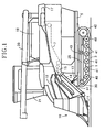
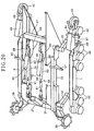
- Fig. 1 is a side view of the combine in its entirety
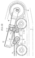
- Fig. 2 a plan view of the same
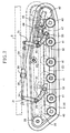
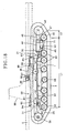
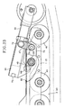
- Fig. 3 a side view of the track frame section
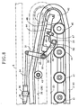
- Fig. 4 a partial enlargement view of the same
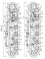
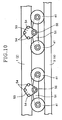
- Fig. 5 is a plan view of the same
- Fig. 6 a partial enlargement view of the same.
- the reference numerals 1 and 2 denote right and left track frames provided with right and left travel crawlers 3 and 4.
- the numeral 5 is a platform to be mounted on said track frames 1 and 2, numeral 6 a threshing section for which the left side is provided with the feed chain 7 and in which the handling barrel 8 and the processing barrel 9 are built.
- Numeral 10 is the reaping section provided with the reaping cutter 11, and the grain stalk conveying mechanism 12.
- Numeral 13 is the hydraulic reaping elevation cylinder for elevating the reaping section 10 around the reaping fulcrum shaft 15 through the reaping frame 14.
- Numeral 16 is the straw discharge cutter close to which the straw discharge chain 17 is located.
- Numeral 18 is the grain tank into which grains are carried from the threshing section 6 through the grain lifting cylinder 19.
- Numeral 20 is the discharge auger for carrying out grains in said tank 18 to the outside of the machine.
- Numeral 21 is the operation cabin provided with an operation section 22 with a steering wheel and the driving seat 23, and numeral 24 is an engine to be mounted under the operation cabin 21 and constructed so that reaping and threshing grain stalks are performed continuously.
- a pair of right and left frames 25 and 26 of the machine are fixed on the bottom surface of said platform 5 by front and rear lateral frames 27, bearing bodies 28 are fixed on both ends of longitudinal extensions of the right and left frames 25 and 26 of the machine, front and rear fulcrum shafts 29 and 30 are supported by bearing bodies 28 in a rotatable manner, a pair of right and left upper swing arms 31 and 32 and a pair of right and left lower swing arms 31 and 32, all of which having an almost same shape and an L-shaped side view, are fixed on both ends of said fulcrum shafts 29 and 30, rear ends of lower swing arms 32 are connected, in a rotatable manner, to support shafts 33 that are supported by said track frames 1 and 2 in a rotatable manner, the upper ends of front and rear upper swing arms 31 are connected to both ends of connecting rods 34 that are extended longitudinally, hydraulic elevation cylinders 35 are installed between connecting rods 34, connecting rods 34 are pushed and pulled longitudinally by hydraulic force of elevation cylinders 35, and right and left track frames 1
- the machine is equipped with drive sprockets 39 installed in the transmission case 37 located in front of platform 5 through the axle case 38.
- a plurality of track rollers 40, equalizer rollers 41 and tension rollers 42 are installed to the external sides of said track frames 1 and 2, and carrier rollers 43 are installed to frames 25 and 26 of the machine.
- track frames 1 and 2 provide the ground contact sides of travel crawlers 3 and 4 with tension.
- the tension frames 44 installed to the rear of track frames 1 and 2 are provided with tension rollers 42 through tension adjusting bolts 45 and idler frames 46, and the tension of travel crawlers 3 and 4 is set at the rear of said tension frames 44 by adjusting the semi-fixed tension for the idler frames 46 by screwing bolts 45.
- front and rear swing arms 31 and 32 are swung around fulcrum shafts 29 and 30 by elevation cylinders 35.
- Each of rollers 40, 41 and 42 and track frames 1 and 2 are elevated to elevate ground contact sides of travel crawlers 3 and 4. Therefore the right and left elevation cylinders 35 can be actuated individually by manual operation of an elevation adjusting switch installed to operation section 22 and by automatic control based on a tilt sensor that detects the lateral tilt of platform 5.
- Platform 5 can be kept nearly horizontal by adjusting the lateral tilt of platform 5 by changing the ground contact height of right and left travel crawlers 3 and 4.
- tension frames 44 are connected to the rear sides of said track frames 1 and 2 through rear idler links 47 serving as a pair of right and left fulcrum links in a longitudinally movable manner.
- Slopes 1a and 2a with low rear ends are formed on the top of each rear end of track frames 1 and 2
- a pair of right and left seat plates 48 are fixed on both sides of the front of said tension frames 44
- front idler links 49 are fixed to said support shafts 33 serving as auxiliary arms at the rear of track frames 1 and 2
- rear lower swing arms 32 and front idler links 49 are connected to seat plates 48 through shafts 50 in a rotatable manner.
- track frames 1 and 2 are located as close to platform 5 as possible, and in a condition where the elevation control action by elevation cylinders 35 is stopped.
- the rear idler links 47 are installed almost vertically, the front idler links 49 are protruded almost horizontally toward the front of support shafts 33, shafts 50 connecting lower swing arms 32 and support shafts 33 to seat plate 48 are supported at a height almost identical to that of support shafts 33, and travel crawlers 3 and 4 are allowed to be in contact with the ground between track rollers 40 at the front and rear ends of track frames 1 and 2, as shown in Figs. 3 and 4.
- the ratio of ground contact length L of right and left travel crawlers 3 and 4 to gauge width B, namely L/B, is set at 1.5 or less to minimize the turning radius, thereby eliminating problems that increase the turning radius and increase the turning resistance moment if said ratio L/B becomes larger than, for example, 1.7.
- connecting rods 34 commonly used as pistons are slid backward by driving elevation cylinders 35, upper swing arms 31 are rotated backward around fulcrum shafts 29 and 30, lower swing arms 32 are rotated downward around fulcrum shafts 29 and 30, track frames 1 and 2 are moved downward and forward, the ground contact side of travel crawlers 3 and 4 supporting track rollers 40 and equalizer rollers 41 are moved downward and forward to increase the ground height of platform 5, shafts 50 of each arm 32 and link 49 are raised around support shafts 33 by rotating the rear lower swing arms 32 downward, the front sides of tension frames 44 are raised from track frames 1 and 2 through seat plates 48, the rear sides of tension frames 44 are lowered toward slopes 1a and 2a, having low rear ends, of track frames 1 and 2 by tilting the rear idler links 47 backward, tension rollers 42 at the rear of tension frames 44 are lowered and moved backward and downward against track frames 1 and 2, the longitudinal ground contact width of travel crawlers 3 and 4 is enlarged toward the rear of track rollers 1 and
- tension rollers 42 are provided in the direction of the ground contact of travel crawlers 3 and 4 in a movable manner.
- the longitudinal ground contact length of travel crawlers 3 and 4 is extended by movement of tension rollers 42, the longitudinal shift of the gravity center of the machine body against the ground contact surface of travel crawlers 3 and 4 is reduced to maintain the longitudinal balance, enlargement of the ground contact area of travel crawlers 3 and 4 results in a decrease of the ground contact pressure, the penetration of travel crawlers 3 and 4 is reduced to improve the travel performance for a direction change, and on, for example, a hard travel surface, such as a dry rice field or an agricultural road, the longitudinal ground contact length of travel crawlers 3 and 4 is reduced to secure the specified turning performance.
- the rear idler links 47 serving as the link mechanism are provided to track frames 1 and 2 in a rotatable manner, tension frames 44 installing tension rollers 42 in a tension adjustable manner are provided to rear idler links 47, tension rollers 42 are moved in a direction of lowering track frames 1 and 2 while moving away from each other, and the longitudinal ground contact length of the rear of travel crawlers 3 and 4 is increased or decreased by moving the tension rollers 42 backward and downward without changing the perimeter of travel crawlers 3 and 4.
- the structure of travel crawlers 3 and 4 is simplified, and an improvement in the travel performance is achieved.
- tension frames 44 installed with tension rollers 42 in a tension adjustable manner are moved in linkage with the elevation control action of swing arms 31 and 32, the ground contact length of the rear of travel crawlers 3 and 4 is increased or decreased by moving tension rollers 42 in a direction opposite to that of longitudinal movement of track frames 1 and 2 by the elevation control action, and a backward shift of the center of gravity of the machine body associated with the elevation control action is minimized to reduce a change in the ground contact pressure at the rear of travel crawlers 3 and 4, thereby eliminating conventional problems, such as excessive penetration of the rear of travel crawlers 3 and 4 caused by the elevation control action, and improving travel performance such as turning ability on a wet rice field or at the bare end area of a field where the penetration of travel crawlers 3 and 4 increases.
- Actions in which the front sides of travel crawlers 3 and 4 are supported by drive sprockets 39, the rear sides of travel crawlers 3 and 4 are supported by tension rollers 42, and track rollers 40 and track frames 1 and 2 are moved forward by machine body raising action of swing arms 31 and 32, are performed in linkage with the action in which tension rollers 42 are moved in the direction of the ground contact of travel crawlers 3 and 4.
- ground contact length is extended toward the rear of travel crawlers 3 and 4 at the elevation control action for raising the machine body to prevent improper penetration of the rear of travel crawlers 3 and 4, to prevent the machine from tilting backward caused by a difference in the penetration between the front and the rear of travel crawlers 3 and 4 due to movement of the center of gravity like conventional machines, and to achieve an improvement in the travel performance on a wet rice field.
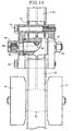
- two pairs of said equalizer rollers 41 are supported by the front and rear axle bearing sections 52 at both ends of the equalizer frames 51 in a rotatable manner.
- the right and left fulcrum brackets 53 are fastened on the right and left sides of said track frames 1 and 2 with bolts 54, the equalizer fulcrum shafts 56 of both threaded ends fastened by nuts 55 are fixed on right and left brackets 53, fulcrum bearing sections 57 in the middle of width between the front and rear of equalizer frames 51 are supported by equalizer fulcrum shafts 56 in a rotatable manner, equalizer frames 51 are provided around equalizer fulcrum shafts 56 in a rotatable manner, the front and rear equalizer rollers 41 are provided in an up and down movable manner, and equalizer frames 51 are held and fastened between right and left fulcrum brackets 53, thereby simplifying the assembly work.
- the end surface of the equalizer fulcrum shaft 56 is provided with a grease injection nozzle 58, and grease is injected to the contact surface between fulcrum shaft 56 and fulcrum bearing section 57 through the nozzle 58 and the injection passage 59 formed in equalizer fulcrum shaft 56, thereby reducing heat generation and damage by wear at fulcrum shaft 56 or fulcrum bearing section 57.
- elevation cylinders 35 are hydraulically connected to hydraulic pump 62 through hydraulic elevation valve 60, a 3-position 4-port solenoid switch type, and the flow-dividing valve 61.
- Elevation valve 60 is switched solenoids 63 and 64 to hydraulically drive the elevation cylinders 35 reciprocally to allow the front and rear pistons 34 to move forward and backward.
- the lateral tilt of platform 5 is detected by tilt sensor 65 and height sensor 67, and the solenoids 63 and 64 are energized by horizontal control circuit 66 allowing the horizontal and vertical controls to automatically drive right and left elevation cylinders 35.
- the machine is provided with right and left elevation cylinders 35 for individually elevating right and left track frames 1 and 2.
- the front and rear connecting rods 34 serving as the front and rear pistons are protruded toward both ends of elevation cylinders 35 connected to the front and rear crawler elevation arms, and elevation cylinders 35 are installed to the machine in a manner movable only upward and downward.
- elevation control functions can be improved by providing elevation cylinders 35 with a double action hydraulic structure.
- upper and lower swing arms 31 and 32 are installed to the external sides of the lateral width of travel crawlers 3 and 4 inside the machine. Thus, interference of lower swing arms 32 with travel crawlers 3 and 4 or accumulation of mud can be prevented.
- hydraulic elevation cylinders 35 are connected between connecting members 68, which connects the front and rear upper swing arms 31. Furthermore, track rollers 40, movable rollers 69, and tension rollers 42 are installed to track frames 1 and 2 to provide the ground contact side of travel crawlers 3 and 4 with tension, and right and left elevation cylinders 35 are individually actuated to perform the elevation control to correct the lateral tilting of platform 5.
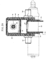
- Track frames 1 and 2 fix a pair of right and left seat plates 70 on both sides of the rear, and connect shafts 50 and 72 at both sides of tension frames 44 to support shafts 33 and link shafts 71, which penetrate between right and left seat plates 70, through front and rear idler links 49 and 47.
- two pairs of bolt mounting seats 73 are fixed in 180-degree symmetrical positions at the external sides of the front ends of tension frames 44, bolt receivers 75 are fixed on said mounting seats 73 with two fastening bolts 74 in a detachable manner, and tension bolts 45 are arranged almost in the middle of nut receiving plate 76 and bolt receiver 75, which are installed to the inside of the front of idler frames 46.
- the opening 80 with a certain length is formed on the tops of track frames 1 and 2 below tension frames 44, thus problems such that mud or stones caught in the clearance between track frames 1 and 2 and tension frames 44 resulting in elevation control failure can be prevented by allowing the mud or stones to fall through opening 80.
- Cylinder receiving plates 83 are fixed on the rear ends of length adjusting rods 82 with turn buckles 81 to constitute connecting members 68.
- Rods 82 and cylinder receiving plates 83 are connected to the top ends of front and rear swing arms 31 through shafts 84 and 85, elevation cylinders 35 are installed to brackets 36 fixed on the rear surface of machine frame 86 of platform 5 through shafts 87, the ends of piston 88 of elevation cylinders 35 are connected to cylinder receiving plates 83 through shafts 89, and shafts 85, 87 and 89 are provided on the extension lines of the shaft centers of pistons 88 of elevation cylinders 35.
- the extension force of pistons 88 can be prevented from acting on cylinder receiving plates 83 as a compressive force to cause deformation, and compact and light cylinder receiving plates 83 can be achieved.
- lower swing arm 32 connecting to the rear swing arm 31 through swing shaft 90 is allowed to commonly use front idler link 49.
- the middle of said arm 32 is connected to shaft 50 to reduce the number of parts, and track frames 1 and 2 and tension frames 44 are connected in a both ends supported condition using swing arms 32 and four idler links consisting of front idler links 47 and right and left rear idler links 47 to make the connection with compact size and appropriate strength.
- spline shaft section 91 at the internal end of swing shaft 90 is connected to end boss section 31a of rear swing arm 31 connected to cylinder receiving plate 83 through shaft 85.
- End boss section 32a of lower swing arm 32 is connected to spline shaft section 92 at the external end of swing shaft 90, and end boss section 32b of lower swing arm 32 and base end boss section 49a of front idler link 49 are connected to internal end spline shaft section 93 of support shaft 33 and shaft section 95 with the external end key 94, respectively.
- swing arms 31 and 32 at the rear outer and inner sides, lower swing arm 32 and support shaft 33, and support shaft 33 and front idler link 49 are provided with the relative position relation, and idler link 49 can be installed in an appropriate position relative to elevation cylinder 35, thereby facilitating the assembly work.
- idler links 47 and 49 are formed so that the link of rear idler link 47 is longer than that of front idler link 49.
- Front idler link 49 and rear idler link 47 are located almost horizontally ("a" line) and almost vertically ("b" line), respectively, at full retraction of elevation cylinder 35.
- Front idler link 49 is moved up around support shaft 33 when elevation cylinder 35 is extended, and rear idler link 47 is rotated backward around link shaft 71.
- numeral 96 is reaping fulcrum base fixed on the top of platform 5 for supporting elevation fulcrum shafts of reaping section 10
- numeral 97 is a roller shaft, of which the base ends are fixed on the top of frames 25 and 26 of the machine for supporting carrier rollers 43 at the horizontally protruding outer end.
- lower frames 25 and 26 at the lower part of the machine are connected to track frames 1 and 2 through lower swing arms 32.
- Lower frames 25 and 26 at the lower part of the machine are provided with inside frame sections 25a and 26a located inside travel crawlers 3 and 4.
- Inside frame sections 25a and 26b are provided with bearing bodies 28 supporting front and rear fulcrum shafts 29 and 30, and lower swing arms 32 are also located inside travel crawlers 3 and 4.
- lower swing arms 32 are located inside travel crawlers 3 and 4 in a compact manner without being allowed to protrude outward from travel crawlers 3 and 4 to improve mud discharge ability and to enable swing arms 32 to swing smoothly.
- Frames 25 and 26 located outside of crawlers 3 and 4 are extended backward without regard to crawlers 3 and 4, thereby increasing freedom of positioning of lateral frame 27 connecting these frames 25 and 26 to improve overall rigidity of frames 25 and 26.
- Nut 78 is applied to the almost central part of idler frame 46 to press idler frame 46 to prevent tension frame 44 from sticking in idler frame 46 to secure smooth extending and retracting actions.
- Bolt receiving member 75 supporting tension bolt 45 is connected to tension frame 44 through fastening bolts 74, which are arranged in equal pitch at the symmetrical position from the center of tension bolt 45.
- forces acting on each fastening bolt 74 can be almost equalized to improve support stability by tension bolt 45.
- Swing arms 31 and 32 are connected to idler links 47 and 49 while keeping the relative mounting position, and track frames 1 and 2 and tension rollers 42 are properly connected to elevation cylinders 35.
- assembly work can be facilitated and elevation controllability of track frames 1 and 2 can be improved.
- Tension frames 44 for installing tension rollers 42 and track frames 1 and 2 are formed separately, and the relative position between track frames 1 and 2 and tension frames 44 is changeable at the time of elevation control of right and left track frames 1 and 2.
- the change of the perimeter of the crawler at the elevation control can be absorbed by movement of track frames 1 and 2 and tension roller 42 to always support travel crawlers 3 and 4 appropriately to improve durability of travel crawlers 3 and 4.
- Tension frames 44 are connected to both right and left sides of track frames 1 and 2 through idler links 47 and 49, and idler links 47 and 49 are provided with both ends supported.
- tension frames 44 and track frames 1 and 2 can be connected compactly with sufficient strength to improve stability during elevation control.
- Swing arm 32 is connected to tension frame 44 through front idler link 49 serving as an auxiliary arm, and idler link 49 is installed almost in parallel with the direction of tension of tension roller 42.
- torsion by the tensioning action acting on support shaft 33 serving as a connecting shaft connecting tension frame 44 and idler link 49 can be limited to improve durability and achieve smooth rotation of tension frame 44 around support shaft 33.
- Swing arms 31 and 32 and idler links 47 and 49 are provided to minimize the change in the perimeter of travel crawlers 3 and 4.
- travel crawlers 3 and 4 can be supported by drive sprockets 39, track rollers 40, and tension rollers 42 in a good condition to stably maintain travel performance without relating to the elevation control.
- Piston 88 of elevation cylinder 35 is connected to connecting member 68 between front and rear elevation arms 31 and 32 connecting right and left track frames 1 and 2 and the machine.
- elevation arms 31 and 32 can be made compact and light in comparison with, for example, piston 88 of elevation cylinder 35 directly connected to elevation arms 31 and 32, and therefore common use and cost reduction of each part of front and rear elevation arms 31 and 32 formed as an identical shape can be achieved.
- Carrier rollers 43 guiding travel crawlers 3 and 4 from the bottom are installed to the side of the machine, and carrier rollers 43 are arranged between the front and rear elevation arms 31 and 32.
- carrier rollers 43 are raised away from track frames 1 and 2 to protect from mud when the machine is controlled to lower track frames 1 and 2 in a wet rice field and so on, and fulcrum shafts 29 and 30 of elevation arms 31 and 32 connected to the sides of the machine can be effectively prevented from interfering with travel crawlers 3 and 4 to stably maintain the travel performance.
- top surfaces of track frames 1 and 2 below tension frames 44 are provided with openings 80 for mud falls, allowing mud and stones to immediately fall down to prevent problems, such as elevation control failure, even if mud or stones are caught in the clearance between track frames 1 and 2 and tension frames 44, and thus elevation control accuracy in correcting lateral tilt of the machine can be improved.
- Lower frames 25 and 26 of the machine connected to track frames 1 and 2 are provided with inside frame sections 25a and 26a located inside travel crawlers 3 and 4, and inside frame sections 25a and 26a are provided with bearing bodies 28 serving as the fulcrum shaft sections of the lower swing arms 32.
- the lower swing arms 32 can be also compactly arranged inside travel crawlers 3 and 4 without being allowed to externally protrude from travel crawlers 3 and 4 to improve mud discharge ability.
Landscapes
- Engineering & Computer Science (AREA)
- Chemical & Material Sciences (AREA)
- Combustion & Propulsion (AREA)
- Transportation (AREA)
- Mechanical Engineering (AREA)
- Harvester Elements (AREA)
- Soil Working Implements (AREA)
- Transplanting Machines (AREA)
- Vehicle Body Suspensions (AREA)
- Agricultural Machines (AREA)
Applications Claiming Priority (3)
| Application Number | Priority Date | Filing Date | Title |
|---|---|---|---|
| JP2000242703A JP4680355B2 (ja) | 2000-08-10 | 2000-08-10 | コンバイン |
| JP2000242703 | 2000-08-10 | ||
| PCT/JP2001/006766 WO2002014140A1 (fr) | 2000-08-10 | 2001-08-06 | Machine agricole mobile |
Publications (3)
| Publication Number | Publication Date |
|---|---|
| EP1308378A1 EP1308378A1 (en) | 2003-05-07 |
| EP1308378A4 EP1308378A4 (en) | 2006-06-07 |
| EP1308378B1 true EP1308378B1 (en) | 2007-12-26 |
Family
ID=18733687
Family Applications (1)
| Application Number | Title | Priority Date | Filing Date |
|---|---|---|---|
| EP01954477A Expired - Lifetime EP1308378B1 (en) | 2000-08-10 | 2001-08-06 | Mobile agricultural machinery |
Country Status (10)
| Country | Link |
|---|---|
| US (1) | US6962222B2 (ja) |
| EP (1) | EP1308378B1 (ja) |
| JP (1) | JP4680355B2 (ja) |
| KR (1) | KR100830551B1 (ja) |
| CN (1) | CN1211244C (ja) |
| AT (1) | ATE382013T1 (ja) |
| AU (2) | AU2001276745B2 (ja) |
| DE (1) | DE60132095T2 (ja) |
| TW (1) | TW515697B (ja) |
| WO (1) | WO2002014140A1 (ja) |
Cited By (1)
| Publication number | Priority date | Publication date | Assignee | Title |
|---|---|---|---|---|
| RU2547318C1 (ru) * | 2014-02-11 | 2015-04-10 | Федеральное государственное бюджетное образовательное учреждение высшего профессионального образования "Курганский государственный университет" | Механизм автоматического натяжения гусениц |
Families Citing this family (49)
| Publication number | Priority date | Publication date | Assignee | Title |
|---|---|---|---|---|
| CN1298578C (zh) * | 2004-11-01 | 2007-02-07 | 大连大学 | 变形履带系统 |
| JP2007055329A (ja) * | 2005-08-23 | 2007-03-08 | Yanmar Co Ltd | 作業車両の走行装置 |
| WO2007023586A1 (ja) * | 2005-08-23 | 2007-03-01 | Yanmar Co., Ltd. | コンバイン |
| DE102006015307A1 (de) * | 2005-11-17 | 2007-05-24 | Terex-Demag Gmbh & Co. Kg | Mobiler Großkran |
| ES2326344T3 (es) * | 2007-01-24 | 2009-10-07 | Klemm Bohrtechnik Gmbh | Dispositivo de traslacion oscilante, particularmente para un aparato de perforacion. |
| US7874387B2 (en) * | 2007-02-15 | 2011-01-25 | Despres Jean | Track extension for vehicle track systems and method |
| US7520575B2 (en) * | 2007-06-29 | 2009-04-21 | Agco Corporation | Tension management system for an endless track of a work machine |
| KR101072654B1 (ko) * | 2007-09-26 | 2011-10-11 | 가부시끼 가이샤 구보다 | 작업차 |
| RU2388642C2 (ru) * | 2008-04-29 | 2010-05-10 | Эдуард Аркадьевич Геращенко | Рычажно-балансирная подвеска гусеничного движителя (варианты) |
| US7967088B2 (en) * | 2008-08-22 | 2011-06-28 | Shawn Watling | Snowmobile suspension and drive train |
| JP5006854B2 (ja) * | 2008-09-22 | 2012-08-22 | 株式会社クボタ | 作業機 |
| KR101146092B1 (ko) | 2009-12-11 | 2012-05-15 | 한국카모플라스트(주) | 충격흡수 홈을 구성한 고무 크로라 |
| KR101603216B1 (ko) * | 2010-05-26 | 2016-03-14 | 한화테크윈 주식회사 | 이동형 감시 로봇 시스템 |
| CA2744681C (en) * | 2010-06-28 | 2018-08-28 | Camoplast Solideal Inc. | All-terrain vehicle (atv) propellable on wheels or endless tracks |
| CA2744630C (en) | 2010-06-30 | 2018-10-09 | Camoplast Solideal Inc. | Wheel of a track assembly of a tracked vehicle |
| DE102010036756A1 (de) * | 2010-07-30 | 2012-02-02 | Claas Selbstfahrende Erntemaschinen Gmbh | Selbstfahrende Erntemaschine |
| US8985250B1 (en) | 2010-12-14 | 2015-03-24 | Camoplast Solideal Inc. | Track drive mode management system and methods |
| US9334001B2 (en) | 2010-12-14 | 2016-05-10 | Camso Inc. | Drive sprocket, drive lug configuration and track drive arrangement for an endless track vehicle |
| US9067631B1 (en) | 2010-12-14 | 2015-06-30 | Camoplast Solideal Inc. | Endless track for traction of a vehicle |
| CA3144939A1 (en) * | 2013-03-25 | 2014-10-02 | Polaris Industries Inc. | Tracked all-terrain vehicle |
| BE1022418B1 (nl) | 2014-01-21 | 2016-03-25 | Cnh Industrial Belgium Nv | Maaidorser met rupsbandeenheden uitgerust met actuatoren die het kantelen tegenwerken |
| JP6067599B2 (ja) * | 2014-01-31 | 2017-01-25 | ヤンマー株式会社 | 走行車両 |
| JP6067598B2 (ja) * | 2014-01-31 | 2017-01-25 | ヤンマー株式会社 | 走行車両 |
| DE102014003964A1 (de) * | 2014-03-20 | 2015-09-24 | Claas Industrietechnik Gmbh | Raupenfahrzeug |
| EP3747746B1 (en) | 2015-03-04 | 2023-05-31 | Camso Inc. | Track system for traction of a vehicle |
| WO2017000068A1 (en) | 2015-06-29 | 2017-01-05 | Camso Inc. | Systems and methods for monitoring a track system for traction of a vehicle |
| CN118058057A (zh) * | 2015-08-07 | 2024-05-24 | 株式会社久保田 | 联合收割机和收割机 |
| RU2732930C1 (ru) * | 2015-09-30 | 2020-09-24 | Брп Финланд Ой | Задняя подвеска снегохода |
| CN106211832B (zh) * | 2016-07-19 | 2020-05-22 | 农业部南京农业机械化研究所 | 一种浮动式三点悬挂装置 |
| US10730551B2 (en) | 2016-08-09 | 2020-08-04 | Polaris Industries Inc. | Tracked all-terrain vehicle |
| SE540523C2 (en) | 2016-11-18 | 2018-09-25 | Bae Systems Haegglunds Ab | Tracked vehicle arranged with pivotable bogie |
| JP6895875B2 (ja) * | 2016-12-19 | 2021-06-30 | 株式会社クボタ | クローラ走行装置 |
| CN106585373B (zh) * | 2016-12-27 | 2024-04-19 | 甘肃省机械科学研究院有限责任公司 | 一种带静液压驱动的姿态可调整履带底盘 |
| SE542243C2 (sv) * | 2017-03-17 | 2020-03-24 | Komatsu Forest Ab | Fjädringsanordning för bandgående fordon |
| CN107351930A (zh) * | 2017-06-16 | 2017-11-17 | 太原理工大学 | 一种履带式底盘的变位装置及方法 |
| DE102017119796A1 (de) * | 2017-08-29 | 2019-02-28 | Claas Selbstfahrende Erntemaschinen Gmbh | Feldhäcksler sowie Verfahren zu dessen Umrüstung |
| US11835955B2 (en) | 2017-12-08 | 2023-12-05 | Camso Inc. | Systems and methods for monitoring off-road vehicles |
| CN108496565A (zh) * | 2018-05-07 | 2018-09-07 | 江苏大学 | 联合收获机可升降履带式底盘 |
| CN108773421A (zh) * | 2018-08-13 | 2018-11-09 | 湖南农业大学 | 一种具有电液调节水平与升降功能的履带底盘 |
| CN108974158A (zh) * | 2018-08-13 | 2018-12-11 | 张祝 | 一种采用电液调节履带底盘水平与升降功能的控制方法 |
| SE542494C2 (sv) * | 2018-09-14 | 2020-05-26 | Komatsu Forest Ab | Lastbärande fordonsdel och ett hjulburet fordon utrustat med en sådan fordonsdel |
| CN110800467A (zh) * | 2019-11-19 | 2020-02-18 | 山东交通学院 | 一种履带式吊振收获机 |
| CN111547146A (zh) * | 2020-03-27 | 2020-08-18 | 金华职业技术学院 | 履带比压自适应机构 |
| WO2022036449A1 (en) * | 2020-08-18 | 2022-02-24 | Camso Inc. | Track system for traction of a vehicle |
| CA3133493A1 (en) * | 2020-10-06 | 2022-04-06 | Camso Inc. | Track system for traction of a vehicle |
| JP7381439B2 (ja) | 2020-12-18 | 2023-11-15 | 株式会社クボタ | 作業車 |
| JP7381440B2 (ja) | 2020-12-18 | 2023-11-15 | 株式会社クボタ | 作業車 |
| KR102612327B1 (ko) * | 2022-12-30 | 2023-12-08 | 장진만 | 다목적 농용 작업기 |
| CN117842223A (zh) * | 2024-03-07 | 2024-04-09 | 襄垣县仁达机电设备有限公司 | 一种履带底盘悬浮式升降机构 |
Family Cites Families (26)
| Publication number | Priority date | Publication date | Assignee | Title |
|---|---|---|---|---|
| FR1401309A (fr) * | 1964-04-20 | 1965-06-04 | Creusot Forges Ateliers | Véhicule à chenilles à poulies de tension réglables longitudinalement et verticalement |
| US3863727A (en) * | 1973-05-10 | 1975-02-04 | Allied Leisure Inc | Suspension system for tracked vehicles |
| DE2344688B2 (de) * | 1973-09-05 | 1979-07-12 | Dr.Ing.H.C. F. Porsche Ag, 7000 Stuttgart | Laufwerk für Gleiskettenfahrzeuge |
| US3938605A (en) * | 1974-06-24 | 1976-02-17 | Clark Equipment Company | Track suspension |
| EP0305647B1 (en) * | 1983-12-20 | 1993-02-03 | Caterpillar Inc. | Frictional driven belted work vehicle |
| JPS63188284A (ja) | 1987-01-31 | 1988-08-03 | Toshiba Corp | 文字読取装置 |
| JPS63188284U (ja) * | 1987-05-26 | 1988-12-02 | ||
| FR2619070B1 (fr) * | 1987-08-07 | 1991-09-06 | Colmant Cuvelier | Dispositif tendeur pour l'element souple ou articule d'un systeme de transmission ou de roulement |
| JPH01142383A (ja) | 1987-11-30 | 1989-06-05 | Taiyo Yuden Co Ltd | セラミック焼成用熱処理炉 |
| US4819754A (en) * | 1987-12-23 | 1989-04-11 | Caterpillar Inc. | Multiple mode vehicle suspension system |
| DE3805494A1 (de) * | 1988-02-22 | 1989-08-31 | Bavaria Cargo Tech | Foerderkugeleinheit |
| US4893883A (en) * | 1988-03-02 | 1990-01-16 | Caterpillar Inc. | Belt tension control system |
| JPH01142383U (ja) * | 1988-03-25 | 1989-09-29 | ||
| JPH0280084A (ja) | 1988-09-16 | 1990-03-20 | Brother Ind Ltd | ミシンに装着可能な刺繍装置 |
| JPH0280084U (ja) * | 1988-12-08 | 1990-06-20 | ||
| JP2824694B2 (ja) * | 1990-07-31 | 1998-11-11 | 三菱農機株式会社 | クローラ走行車輌における機体制御装置 |
| US5191952A (en) * | 1991-09-19 | 1993-03-09 | Caterpillar Inc. | Track-type vehicle having steerable wheels |
| JPH0582772A (ja) | 1991-09-20 | 1993-04-02 | Mitsubishi Electric Corp | 半導体装置及びその製造方法 |
| JP3194039B2 (ja) * | 1991-11-01 | 2001-07-30 | ヤンマー農機株式会社 | 農作業機の水平制御装置 |
| JP2594108Y2 (ja) * | 1992-04-20 | 1999-04-19 | セイレイ工業株式会社 | コンバイン用走行装置 |
| JP3270975B2 (ja) * | 1993-02-19 | 2002-04-02 | ヤンマー農機株式会社 | クローラ走行装置の水平制御機構 |
| JP3049511B2 (ja) * | 1996-04-10 | 2000-06-05 | 株式会社小松製作所 | クローラ式車両のクローラ装置 |
| US5775447A (en) * | 1996-09-25 | 1998-07-07 | Caterpillar Inc. | Material deflecting assembly for a track assembly |
| JPH10100953A (ja) * | 1996-09-27 | 1998-04-21 | Seirei Ind Co Ltd | 農作業機 |
| US6024183A (en) * | 1997-10-24 | 2000-02-15 | Caterpillar Inc. | Track belt tension management system |
| US6164399A (en) * | 1999-06-02 | 2000-12-26 | Sercel, Inc. | Track-type carriage system for heavy vehicles |
-
2000
- 2000-08-10 JP JP2000242703A patent/JP4680355B2/ja not_active Expired - Fee Related
-
2001
- 2001-08-06 US US10/343,441 patent/US6962222B2/en not_active Expired - Fee Related
- 2001-08-06 EP EP01954477A patent/EP1308378B1/en not_active Expired - Lifetime
- 2001-08-06 WO PCT/JP2001/006766 patent/WO2002014140A1/ja active IP Right Grant
- 2001-08-06 AU AU2001276745A patent/AU2001276745B2/en not_active Ceased
- 2001-08-06 AT AT01954477T patent/ATE382013T1/de not_active IP Right Cessation
- 2001-08-06 AU AU7674501A patent/AU7674501A/xx active Pending
- 2001-08-06 DE DE60132095T patent/DE60132095T2/de not_active Expired - Lifetime
- 2001-08-06 CN CNB018139957A patent/CN1211244C/zh not_active Expired - Fee Related
- 2001-08-06 KR KR1020037001962A patent/KR100830551B1/ko not_active IP Right Cessation
- 2001-08-09 TW TW090119541A patent/TW515697B/zh not_active IP Right Cessation
Cited By (1)
| Publication number | Priority date | Publication date | Assignee | Title |
|---|---|---|---|---|
| RU2547318C1 (ru) * | 2014-02-11 | 2015-04-10 | Федеральное государственное бюджетное образовательное учреждение высшего профессионального образования "Курганский государственный университет" | Механизм автоматического натяжения гусениц |
Also Published As
| Publication number | Publication date |
|---|---|
| EP1308378A4 (en) | 2006-06-07 |
| CN1446165A (zh) | 2003-10-01 |
| DE60132095D1 (de) | 2008-02-07 |
| JP4680355B2 (ja) | 2011-05-11 |
| DE60132095T2 (de) | 2008-12-11 |
| US6962222B2 (en) | 2005-11-08 |
| US20030161687A1 (en) | 2003-08-28 |
| KR100830551B1 (ko) | 2008-05-22 |
| EP1308378A1 (en) | 2003-05-07 |
| KR20030022383A (ko) | 2003-03-15 |
| WO2002014140A1 (fr) | 2002-02-21 |
| JP2002053083A (ja) | 2002-02-19 |
| ATE382013T1 (de) | 2008-01-15 |
| AU7674501A (en) | 2002-02-25 |
| AU2001276745B2 (en) | 2004-12-09 |
| TW515697B (en) | 2003-01-01 |
| CN1211244C (zh) | 2005-07-20 |
Similar Documents
| Publication | Publication Date | Title |
|---|---|---|
| EP1308378B1 (en) | Mobile agricultural machinery | |
| JP3831531B2 (ja) | コンバインの走行装置 | |
| US7200981B2 (en) | Support wheel arrangement for agricultural working machine, and agricultural working machine provided therewith | |
| JP4584502B2 (ja) | 移動農機 | |
| JP2003048574A (ja) | 移動農機の走行クローラ装置 | |
| JP4727854B2 (ja) | 移動農機 | |
| JP4727855B2 (ja) | 移動農機 | |
| JP2861145B2 (ja) | コンバイン等の姿勢制御装置 | |
| JPH06239271A (ja) | クローラ走行装置の水平制御機構 | |
| JP2688185B2 (ja) | 履帯式走行装置の昇降装置 | |
| JP2861141B2 (ja) | コンバインの走行制御装置 | |
| JP2004017923A (ja) | 走行車 | |
| JP3827122B2 (ja) | コンバイン | |
| JP2522031Y2 (ja) | コンバインのバランス調節装置 | |
| JPS63149275A (ja) | 作業車のクロ−ラ走行装置 | |
| JPH01293283A (ja) | 履帯式走行車両における履帯式走行装置の昇降装置 | |
| JP2536191B2 (ja) | コンバイン等の走行装置 | |
| JPH06340277A (ja) | クローラ走行装置 | |
| JPH11155345A (ja) | 作業車の走行装置 | |
| CN117163174A (zh) | 一种用于甘薯收获机的可调节履带 | |
| JPH01301477A (ja) | 作業車のクローラ走行装置 | |
| JP3890677B2 (ja) | 作業車の走行装置 | |
| JPH05254457A (ja) | コンバイン等のクローラ旋回制御装置 | |
| JPH0757139B2 (ja) | コンバイン等の走行装置 | |
| JPH08225087A (ja) | コンバインの走行装置 |
Legal Events
| Date | Code | Title | Description |
|---|---|---|---|
| PUAI | Public reference made under article 153(3) epc to a published international application that has entered the european phase |
Free format text: ORIGINAL CODE: 0009012 |
|
| 17P | Request for examination filed |
Effective date: 20030203 |
|
| AK | Designated contracting states |
Designated state(s): AT BE CH CY DE DK ES FI FR GB GR IE IT LI LU MC NL PT SE TR |
|
| A4 | Supplementary search report drawn up and despatched |
Effective date: 20060428 |
|
| RIC1 | Information provided on ipc code assigned before grant |
Ipc: B62D 55/116 20060101AFI20020226BHEP Ipc: B62D 55/30 20060101ALI20060424BHEP Ipc: B62D 55/084 20060101ALI20060424BHEP Ipc: B62D 55/10 20060101ALI20060424BHEP |
|
| 17Q | First examination report despatched |
Effective date: 20060821 |
|
| GRAP | Despatch of communication of intention to grant a patent |
Free format text: ORIGINAL CODE: EPIDOSNIGR1 |
|
| GRAS | Grant fee paid |
Free format text: ORIGINAL CODE: EPIDOSNIGR3 |
|
| GRAA | (expected) grant |
Free format text: ORIGINAL CODE: 0009210 |
|
| AK | Designated contracting states |
Kind code of ref document: B1 Designated state(s): AT BE CH CY DE DK ES FI FR GB GR IE IT LI LU MC NL PT SE TR |
|
| REG | Reference to a national code |
Ref country code: GB Ref legal event code: FG4D |
|
| REG | Reference to a national code |
Ref country code: IE Ref legal event code: FG4D |
|
| REG | Reference to a national code |
Ref country code: CH Ref legal event code: EP |
|
| REF | Corresponds to: |
Ref document number: 60132095 Country of ref document: DE Date of ref document: 20080207 Kind code of ref document: P |
|
| PG25 | Lapsed in a contracting state [announced via postgrant information from national office to epo] |
Ref country code: SE Free format text: LAPSE BECAUSE OF FAILURE TO SUBMIT A TRANSLATION OF THE DESCRIPTION OR TO PAY THE FEE WITHIN THE PRESCRIBED TIME-LIMIT Effective date: 20080326 Ref country code: LI Free format text: LAPSE BECAUSE OF FAILURE TO SUBMIT A TRANSLATION OF THE DESCRIPTION OR TO PAY THE FEE WITHIN THE PRESCRIBED TIME-LIMIT Effective date: 20071226 Ref country code: CH Free format text: LAPSE BECAUSE OF FAILURE TO SUBMIT A TRANSLATION OF THE DESCRIPTION OR TO PAY THE FEE WITHIN THE PRESCRIBED TIME-LIMIT Effective date: 20071226 |
|
| PG25 | Lapsed in a contracting state [announced via postgrant information from national office to epo] |
Ref country code: NL Free format text: LAPSE BECAUSE OF FAILURE TO SUBMIT A TRANSLATION OF THE DESCRIPTION OR TO PAY THE FEE WITHIN THE PRESCRIBED TIME-LIMIT Effective date: 20071226 Ref country code: FI Free format text: LAPSE BECAUSE OF FAILURE TO SUBMIT A TRANSLATION OF THE DESCRIPTION OR TO PAY THE FEE WITHIN THE PRESCRIBED TIME-LIMIT Effective date: 20071226 |
|
| NLV1 | Nl: lapsed or annulled due to failure to fulfill the requirements of art. 29p and 29m of the patents act | ||
| REG | Reference to a national code |
Ref country code: CH Ref legal event code: PL |
|
| PG25 | Lapsed in a contracting state [announced via postgrant information from national office to epo] |
Ref country code: AT Free format text: LAPSE BECAUSE OF FAILURE TO SUBMIT A TRANSLATION OF THE DESCRIPTION OR TO PAY THE FEE WITHIN THE PRESCRIBED TIME-LIMIT Effective date: 20071226 |
|
| PG25 | Lapsed in a contracting state [announced via postgrant information from national office to epo] |
Ref country code: ES Free format text: LAPSE BECAUSE OF FAILURE TO SUBMIT A TRANSLATION OF THE DESCRIPTION OR TO PAY THE FEE WITHIN THE PRESCRIBED TIME-LIMIT Effective date: 20080406 |
|
| ET | Fr: translation filed | ||
| PG25 | Lapsed in a contracting state [announced via postgrant information from national office to epo] |
Ref country code: BE Free format text: LAPSE BECAUSE OF FAILURE TO SUBMIT A TRANSLATION OF THE DESCRIPTION OR TO PAY THE FEE WITHIN THE PRESCRIBED TIME-LIMIT Effective date: 20071226 |
|
| PG25 | Lapsed in a contracting state [announced via postgrant information from national office to epo] |
Ref country code: PT Free format text: LAPSE BECAUSE OF FAILURE TO SUBMIT A TRANSLATION OF THE DESCRIPTION OR TO PAY THE FEE WITHIN THE PRESCRIBED TIME-LIMIT Effective date: 20080526 |
|
| PG25 | Lapsed in a contracting state [announced via postgrant information from national office to epo] |
Ref country code: DK Free format text: LAPSE BECAUSE OF FAILURE TO SUBMIT A TRANSLATION OF THE DESCRIPTION OR TO PAY THE FEE WITHIN THE PRESCRIBED TIME-LIMIT Effective date: 20071226 |
|
| PLBE | No opposition filed within time limit |
Free format text: ORIGINAL CODE: 0009261 |
|
| STAA | Information on the status of an ep patent application or granted ep patent |
Free format text: STATUS: NO OPPOSITION FILED WITHIN TIME LIMIT |
|
| 26N | No opposition filed |
Effective date: 20080929 |
|
| PG25 | Lapsed in a contracting state [announced via postgrant information from national office to epo] |
Ref country code: GR Free format text: LAPSE BECAUSE OF FAILURE TO SUBMIT A TRANSLATION OF THE DESCRIPTION OR TO PAY THE FEE WITHIN THE PRESCRIBED TIME-LIMIT Effective date: 20080327 |
|
| PG25 | Lapsed in a contracting state [announced via postgrant information from national office to epo] |
Ref country code: MC Free format text: LAPSE BECAUSE OF NON-PAYMENT OF DUE FEES Effective date: 20080831 |
|
| GBPC | Gb: european patent ceased through non-payment of renewal fee |
Effective date: 20080806 |
|
| PG25 | Lapsed in a contracting state [announced via postgrant information from national office to epo] |
Ref country code: CY Free format text: LAPSE BECAUSE OF FAILURE TO SUBMIT A TRANSLATION OF THE DESCRIPTION OR TO PAY THE FEE WITHIN THE PRESCRIBED TIME-LIMIT Effective date: 20071226 Ref country code: IE Free format text: LAPSE BECAUSE OF NON-PAYMENT OF DUE FEES Effective date: 20080806 |
|
| PG25 | Lapsed in a contracting state [announced via postgrant information from national office to epo] |
Ref country code: GB Free format text: LAPSE BECAUSE OF NON-PAYMENT OF DUE FEES Effective date: 20080806 |
|
| PG25 | Lapsed in a contracting state [announced via postgrant information from national office to epo] |
Ref country code: LU Free format text: LAPSE BECAUSE OF NON-PAYMENT OF DUE FEES Effective date: 20080806 |
|
| PG25 | Lapsed in a contracting state [announced via postgrant information from national office to epo] |
Ref country code: TR Free format text: LAPSE BECAUSE OF FAILURE TO SUBMIT A TRANSLATION OF THE DESCRIPTION OR TO PAY THE FEE WITHIN THE PRESCRIBED TIME-LIMIT Effective date: 20071226 |
|
| REG | Reference to a national code |
Ref country code: FR Ref legal event code: TP |
|
| PG25 | Lapsed in a contracting state [announced via postgrant information from national office to epo] |
Ref country code: IT Free format text: LAPSE BECAUSE OF NON-PAYMENT OF DUE FEES Effective date: 20100806 |
|
| PGRI | Patent reinstated in contracting state [announced from national office to epo] |
Ref country code: IT Effective date: 20110616 |
|
| PGFP | Annual fee paid to national office [announced via postgrant information from national office to epo] |
Ref country code: DE Payment date: 20110829 Year of fee payment: 11 Ref country code: FR Payment date: 20110826 Year of fee payment: 11 |
|
| PGFP | Annual fee paid to national office [announced via postgrant information from national office to epo] |
Ref country code: IT Payment date: 20110829 Year of fee payment: 11 |
|
| REG | Reference to a national code |
Ref country code: FR Ref legal event code: ST Effective date: 20130430 |
|
| PG25 | Lapsed in a contracting state [announced via postgrant information from national office to epo] |
Ref country code: IT Free format text: LAPSE BECAUSE OF NON-PAYMENT OF DUE FEES Effective date: 20120806 |
|
| PG25 | Lapsed in a contracting state [announced via postgrant information from national office to epo] |
Ref country code: DE Free format text: LAPSE BECAUSE OF NON-PAYMENT OF DUE FEES Effective date: 20130301 |
|
| PG25 | Lapsed in a contracting state [announced via postgrant information from national office to epo] |
Ref country code: FR Free format text: LAPSE BECAUSE OF NON-PAYMENT OF DUE FEES Effective date: 20120831 |
|
| REG | Reference to a national code |
Ref country code: DE Ref legal event code: R119 Ref document number: 60132095 Country of ref document: DE Effective date: 20130301 |