EP1072458B1 - Adaptive Steuerung der Geschwindigkeit eines Fahrzeugs - Google Patents
Adaptive Steuerung der Geschwindigkeit eines Fahrzeugs Download PDFInfo
- Publication number
- EP1072458B1 EP1072458B1 EP00306451A EP00306451A EP1072458B1 EP 1072458 B1 EP1072458 B1 EP 1072458B1 EP 00306451 A EP00306451 A EP 00306451A EP 00306451 A EP00306451 A EP 00306451A EP 1072458 B1 EP1072458 B1 EP 1072458B1
- Authority
- EP
- European Patent Office
- Prior art keywords
- speed
- vehicle
- vehicle speed
- control
- value
- Prior art date
- Legal status (The legal status is an assumption and is not a legal conclusion. Google has not performed a legal analysis and makes no representation as to the accuracy of the status listed.)
- Expired - Lifetime
Links
- 230000003044 adaptive effect Effects 0.000 title claims description 92
- 230000001133 acceleration Effects 0.000 claims description 81
- 238000001514 detection method Methods 0.000 claims description 30
- 230000000977 initiatory effect Effects 0.000 claims description 18
- 238000012545 processing Methods 0.000 claims description 17
- 230000005540 biological transmission Effects 0.000 claims description 9
- 230000000670 limiting effect Effects 0.000 claims description 8
- 238000000034 method Methods 0.000 claims description 6
- 230000000694 effects Effects 0.000 claims description 2
- 230000006870 function Effects 0.000 description 16
- 230000009471 action Effects 0.000 description 5
- 238000012360 testing method Methods 0.000 description 4
- 238000005516 engineering process Methods 0.000 description 3
- 230000008569 process Effects 0.000 description 3
- 238000002485 combustion reaction Methods 0.000 description 2
- 230000001276 controlling effect Effects 0.000 description 2
- 230000000994 depressogenic effect Effects 0.000 description 2
- 238000010586 diagram Methods 0.000 description 2
- 238000001914 filtration Methods 0.000 description 2
- 230000015654 memory Effects 0.000 description 2
- 230000004044 response Effects 0.000 description 2
- 230000001960 triggered effect Effects 0.000 description 2
- 230000004075 alteration Effects 0.000 description 1
- 230000003247 decreasing effect Effects 0.000 description 1
- 230000005611 electricity Effects 0.000 description 1
- 230000006872 improvement Effects 0.000 description 1
- 238000005259 measurement Methods 0.000 description 1
- 238000012986 modification Methods 0.000 description 1
- 230000004048 modification Effects 0.000 description 1
- 230000007420 reactivation Effects 0.000 description 1
- 230000009467 reduction Effects 0.000 description 1
- 230000001172 regenerating effect Effects 0.000 description 1
- 230000001105 regulatory effect Effects 0.000 description 1
Images


Classifications
-
- B—PERFORMING OPERATIONS; TRANSPORTING
- B60—VEHICLES IN GENERAL
- B60K—ARRANGEMENT OR MOUNTING OF PROPULSION UNITS OR OF TRANSMISSIONS IN VEHICLES; ARRANGEMENT OR MOUNTING OF PLURAL DIVERSE PRIME-MOVERS IN VEHICLES; AUXILIARY DRIVES FOR VEHICLES; INSTRUMENTATION OR DASHBOARDS FOR VEHICLES; ARRANGEMENTS IN CONNECTION WITH COOLING, AIR INTAKE, GAS EXHAUST OR FUEL SUPPLY OF PROPULSION UNITS IN VEHICLES
- B60K31/00—Vehicle fittings, acting on a single sub-unit only, for automatically controlling vehicle speed, i.e. preventing speed from exceeding an arbitrarily established velocity or maintaining speed at a particular velocity, as selected by the vehicle operator
- B60K31/0008—Vehicle fittings, acting on a single sub-unit only, for automatically controlling vehicle speed, i.e. preventing speed from exceeding an arbitrarily established velocity or maintaining speed at a particular velocity, as selected by the vehicle operator including means for detecting potential obstacles in vehicle path
-
- B—PERFORMING OPERATIONS; TRANSPORTING
- B60—VEHICLES IN GENERAL
- B60K—ARRANGEMENT OR MOUNTING OF PROPULSION UNITS OR OF TRANSMISSIONS IN VEHICLES; ARRANGEMENT OR MOUNTING OF PLURAL DIVERSE PRIME-MOVERS IN VEHICLES; AUXILIARY DRIVES FOR VEHICLES; INSTRUMENTATION OR DASHBOARDS FOR VEHICLES; ARRANGEMENTS IN CONNECTION WITH COOLING, AIR INTAKE, GAS EXHAUST OR FUEL SUPPLY OF PROPULSION UNITS IN VEHICLES
- B60K31/00—Vehicle fittings, acting on a single sub-unit only, for automatically controlling vehicle speed, i.e. preventing speed from exceeding an arbitrarily established velocity or maintaining speed at a particular velocity, as selected by the vehicle operator
- B60K31/02—Vehicle fittings, acting on a single sub-unit only, for automatically controlling vehicle speed, i.e. preventing speed from exceeding an arbitrarily established velocity or maintaining speed at a particular velocity, as selected by the vehicle operator including electrically actuated servomechanism including an electric control system or a servomechanism in which the vehicle velocity affecting element is actuated electrically
- B60K31/04—Vehicle fittings, acting on a single sub-unit only, for automatically controlling vehicle speed, i.e. preventing speed from exceeding an arbitrarily established velocity or maintaining speed at a particular velocity, as selected by the vehicle operator including electrically actuated servomechanism including an electric control system or a servomechanism in which the vehicle velocity affecting element is actuated electrically and means for comparing one electrical quantity, e.g. voltage, pulse, waveform, flux, or the like, with another quantity of a like kind, which comparison means is involved in the development of an electrical signal which is fed into the controlling means
- B60K31/042—Vehicle fittings, acting on a single sub-unit only, for automatically controlling vehicle speed, i.e. preventing speed from exceeding an arbitrarily established velocity or maintaining speed at a particular velocity, as selected by the vehicle operator including electrically actuated servomechanism including an electric control system or a servomechanism in which the vehicle velocity affecting element is actuated electrically and means for comparing one electrical quantity, e.g. voltage, pulse, waveform, flux, or the like, with another quantity of a like kind, which comparison means is involved in the development of an electrical signal which is fed into the controlling means where at least one electrical quantity is set by the vehicle operator
- B60K31/045—Vehicle fittings, acting on a single sub-unit only, for automatically controlling vehicle speed, i.e. preventing speed from exceeding an arbitrarily established velocity or maintaining speed at a particular velocity, as selected by the vehicle operator including electrically actuated servomechanism including an electric control system or a servomechanism in which the vehicle velocity affecting element is actuated electrically and means for comparing one electrical quantity, e.g. voltage, pulse, waveform, flux, or the like, with another quantity of a like kind, which comparison means is involved in the development of an electrical signal which is fed into the controlling means where at least one electrical quantity is set by the vehicle operator in a memory, e.g. a capacitor
- B60K31/047—Vehicle fittings, acting on a single sub-unit only, for automatically controlling vehicle speed, i.e. preventing speed from exceeding an arbitrarily established velocity or maintaining speed at a particular velocity, as selected by the vehicle operator including electrically actuated servomechanism including an electric control system or a servomechanism in which the vehicle velocity affecting element is actuated electrically and means for comparing one electrical quantity, e.g. voltage, pulse, waveform, flux, or the like, with another quantity of a like kind, which comparison means is involved in the development of an electrical signal which is fed into the controlling means where at least one electrical quantity is set by the vehicle operator in a memory, e.g. a capacitor the memory being digital
-
- B—PERFORMING OPERATIONS; TRANSPORTING
- B60—VEHICLES IN GENERAL
- B60W—CONJOINT CONTROL OF VEHICLE SUB-UNITS OF DIFFERENT TYPE OR DIFFERENT FUNCTION; CONTROL SYSTEMS SPECIALLY ADAPTED FOR HYBRID VEHICLES; ROAD VEHICLE DRIVE CONTROL SYSTEMS FOR PURPOSES NOT RELATED TO THE CONTROL OF A PARTICULAR SUB-UNIT
- B60W50/00—Details of control systems for road vehicle drive control not related to the control of a particular sub-unit, e.g. process diagnostic or vehicle driver interfaces
- B60W2050/0001—Details of the control system
- B60W2050/0019—Control system elements or transfer functions
- B60W2050/0022—Gains, weighting coefficients or weighting functions
Definitions
- the present invention relates to an adaptive vehicle speed control system capable of performing a so-called “following control” function according to which a host vehicle can follow a preceding vehicle, while maintaining the host vehicle's distance from the preceding vehicle at a desired preset inter-vehicle distance, and specifically to the improvement of an automatic speed-control technology containing a following control function as well as a constant-speed control function.
- the adaptive vehicle speed control system disclosed in the Japanese Patent Provisional Publication No. 8-192662 includes an operation switch serving as a man-machine interface and outputting a start command signal needed to initiate the following control function and constant-speed control function, and an electronic control unit (ECU) equipped with a processor.
- the processor includes a first vehicle speed setting section and a second vehicle speed setting section. The first vehicle speed setting section sets, during a constant-speed control mode, a set vehicle speed at a vehicle road speed the vehicle was traveling at when the start command signal was output. And the second vehicle speed setting section sets, during a following control mode, a set vehicle speed at a predetermined value higher than the vehicle road speed the vehicle was traveling at when the start command signal was output.
- the set vehicle speed may be set to such an excessively low speed.
- the brakes tend to apply automatically each time the limiting action of the vehicle speed to the excessively low speed (determined as the set vehicle speed) occurs.
- the set vehicle speed set to such an excessively low speed there is an increased tendency for the braking action to undesiredly continue so as to maintain the set vehicle speed at the excessively low speed, and thus the driver/vehicle occupants may feel uncomfortable.
- the present invention provides an adaptive vehicle speed control system as set forth in claim 1 and a method as set forth in claim 9.
- an adaptive vehicle speed control system comprises a vehicle speed detection device which detects a host vehicle speed of a host vehicle which is subjected to adaptive vehicle speed control including preceding vehicle following control and vehicle speed control, an inter-vehicle distance detection device which detects an inter-vehicle distance between the host vehicle and a preceding vehicle ahead of the host vehicle, a set-vehicle-speed setting device having a man-machine interface for setting a set vehicle speed, a vehicle speed controller comprising a desired inter-vehicle distance arithmetic-processing section calculating a desired inter-vehicle distance based on at least the host vehicle speed, a following control section determining a desired speed of the host vehicle based on the host vehicle speed and the inter-vehicle distance so that the inter-vehicle distance is brought closer to the desired inter-vehicle distance in presence of detection of the preceding vehicle, and a vehicle-speed adjustment device which adjusts the host vehicle speed
- an adaptive vehicle speed control method which comprises detecting a vehicle speed of a host vehicle which is subjected to adaptive vehicle speed control including preceding vehicle following control and vehicle speed control, detecting an inter-vehicle distance between the host vehicle and a preceding vehicle ahead of the host vehicle, setting a set vehicle speed through a man-machine interface, calculating a desired inter-vehicle distance based on at least the host vehicle speed, determining a desired speed of the host vehicle based on the host vehicle speed and the inter-vehicle distance so that the inter-vehicle distance is brought closer to the desired inter-vehicle distance in presence of detection of the preceding vehicle, adjusting the host vehicle speed to the desired speed, outputting a command signal indicative of initiation of the adaptive vehicle speed control including the following control and the vehicle speed control, and setting the desired speed to a speed value higher than a low-speed threshold value, in presence of output of the command signal under a specified condition where the host vehicle speed is below the low-speed threshold
- the adaptive vehicle speed control system of the invention is exemplified in a rear-wheel drive vehicle having front-left and front-right driven wheels 1FL and 1FR and rear-left and rear-right drive wheels 1RL and 1RR.
- Engine power output (engine torque) is transmitted from an internal combustion engine 2 through an automatic transmission 3, a propeller shaft 4, and a final reduction gear 5, and via axle driveshafts (6, 6) to the drive wheels (1RL, 1RR) .
- the automatic transmission is a typical automatic transmission which permits creeping travel of the vehicle without depression of an accelerator in a low vehicle speed range .
- Disk brakes (7, 7, 7, 7) are provided at the respective road wheels (1FL, 1FR, 1RL, 1RR) to provide braking action.
- Hydraulic brake pressure of the individual wheel-brake cylinders respectively associated with the disk brakes is regulated or controlled by means of a brake control system 8.
- Brake control system 8 is designed to produce a braking pressure based on the magnitude of depression of a brake pedal 16, and also to produce a braking pressure based on a command signal which is output by an adaptive vehicle speed control ECU or an adaptive cruise control controller (ACC controller) 30 and is indicative of a desired braking pressure.
- An engine output control system 9 is provided at engine 2 for controlling engine output or engine torque .
- the engine output control system 9 uses the former way, that is, the throttle-opening adjustment.
- An inter-vehicle distance sensor 12 (serving as an inter-vehicle distance detection means) is mounted on the lower part of the front end of a host vehicle, which is subjected to adaptive vehicle speed control (adaptive cruise control), to capture, recognize, sense,or detect the preceding vehicle (relevant target vehicle) and to monitor the separating distance between the host vehicle and the preceding vehicle.
- a scanning laser radar sensor is used as the inter-vehicle distance sensor.
- the scanning laser radar sensor includes a scanning device containing both a transmitter and a receiver.
- the scanning device of the laser radar sensor transmits a pulse of light (laser beam) in a horizontal line, back and forth.
- the scanning device measures the time of flight of the pulse of light, and then the inter-vehicle distance is calculated on the basis of the time interval from the transmitted pulse (the time when the laser beam is emitted from the host vehicle) to the received pulse (the time when the receiver receives the laser wave reflected from the preceding vehicle).
- Adaptive vehicle speed control ECU 30 (ACC controller) generally comprises a microcomputer.
- the ACC controller includes an input/output interface (I/O), memories (RAM, ROM), and a microprocessor or a central processing unit (CPU) .
- the input/output interface (I/O) of ACC controller 30 receives input information from various engine/vehicle switches and sensors, namely front-left and front-right wheel-speed sensors 13FL, 13FR, an accelerator switch 15, a brake switch 17, a set switch 18, a cancel switch 19, and a resume switch 20.
- Front-left and front-right wheel-speed sensors 13FL and 13FR are located at the respective front road wheels 1FL and 1FR, to sense front-left and front-right wheel speeds V WFL and V WFR .
- Accelerator switch 15 is located near an accelerator pedal 14 to detect depression of accelerator pedal 14.
- Brake switch 17 is located near the brake pedal 16 to detect depression of brake pedal 16.
- Set switch 18 is one of the three operation switches (18, 19, 20) functioning as a man-machine interface.
- Set switch 18 serves as a speed-decreasing switch needed to decrease the set vehicle speed and is also provided to initiate or engage the adaptive vehicle speed control (containing the following control function).
- Cancel switch 19 is provided to disengage or cancel the adaptive vehicle speed control function.
- Resume switch 20 serves as a speed-increasing switch needed to increase the set vehicle speed and is also provided to read out the set vehicle speed stored just before disengagement or cancellation of the adaptive vehicle speed control, and to resume the stored vehicle speed.
- the central processing unit CPU allows the access by the I/O interface of input informational data signals from the previously-discussed engine/vehicle switches and sensors 13FL, 13FR, 15, 17, 18, 19, and 20.
- the CPU of ACC controller 30 is responsible for carrying the engine-output-control/brake-control program stored in memories and is capable of performing necessary arithmetic and logic operations containing an adaptive vehicle-speed-control management processing (containing an electronic engine output control achieved through engine output control system 9 as well as an active brake control achieved through brake control system 8) shown in Fig. 2.
- Computational results arithmetic calculation results
- calculated output signals solenoid drive currents
- the adaptive vehicle-speed-control management processing is executed as a main program by the CPU of ACC controller 30.
- step S2 occurs.
- step S2 a check is made to determine whether the set switch 18 is turned on or off.
- ACC controller 30 determines that there is no requirement for the adaptive vehicle speed control.
- step S2 the program proceeds to step S3.
- step S3 the system initiates the adaptive vehicle-speed-control subroutine (or the following-control processing) shown in Fig. 3.
- step S4 the adaptive vehicle-speed-control indicative flag FC is set at "1", and at the same time an adaptive vehicle-speed-control initiation indicative flag FS is set at "1".
- flag FS 1 means a starting period of the adaptive vehicle speed control.
- step S5 a test is made to determine whether a predetermined adaptive vehicle-speed-control cancellation condition (simply, an ACC control cancellation condition) is met .
- the ACC control cancellation condition corresponds to either of a first condition where cancel switch 19 is turned on, a second condition where accelerator switch 15 is turned on, and a third condition where brake switch 17 is turned on.
- the program is returned to step S1.
- step S6 the system terminates the adaptive vehicle-speed-control operating mode (or the following-control processing shown in Fig. 3). Then, step S7 occurs.
- step S7 the adaptive vehicle-speed-control indicative flag FC is reset to "0". After steps S4 or S7, the program is returned to step S1.
- Fig. 3 there is shown the adaptive vehicle-speed-control subroutine (the following-control processing) related to steps S3 or S6 of Fig. 2.
- the sub-routine shown in Fig. 3 is executed as time-triggered interrupt routines to be triggered every predetermined time intervals such as 10 msec.
- step S11 first of all, the number of pulses of the pulse signal from each of the wheel-speed sensors 13FL and 13FR is counted or the pulse width of the pulse signal from each wheel speed sensor (13FL, 13FR) is measured.
- the CPU of ACC controller 30 On the basis of the result of measurement of the pulse width or the number of pulses counted and the circumferential length of a tire of each of the front road wheels (1FL, 1FR), the CPU of ACC controller 30 is able to calculate or determine both a vehicle speed based on front-left wheel speed V WFL and a vehicle speed based on front-right wheel speed V WFR . Then, an average value of these vehicle speeds is calculated and determined as a host vehicle speed Vs of the host vehicle.
- step S12 the inter-vehicle distance L between the host vehicle and the preceding vehicle (the relevant target vehicle), detected by the inter-vehicle distance sensor 12, is read.
- step S13 of Fig. 3 the system executes the set-vehicle-speed (V SET ) setting subroutine shown in Fig. 4. Thereafter, the routine proceeds from step S13 to step S14.
- step S14 of Fig. 3 the system executes maximum acceleration ( ⁇ MAX ) setting subroutine shown in Fig. 5.
- step S15 of Fig. 3 the system executes the desired acceleration/deceleration (G*) arithmetic calculation routine shown in Fig. 6. Then, at step S16 of Fig.
- the system executes the active engine output control and active brake control (active vehicle acceleration/deceleration control) based on desired acceleration/deceleration value G* calculated at step S15, by way of the throttle valve operated by engine output control system 9 and the brakes operated by brake control system 8.
- active vehicle acceleration/deceleration control active vehicle acceleration/deceleration control
- V SET set-vehicle-speed setting subroutine
- step S21 a check is made to determine whether set switch 18 is turned on.
- step S22 occurs.
- step S22 a check is made to determine whether adaptive vehicle-speed-control initiation indicative flag FS is set. When flag FS is set at "1", the ACC controller 30 determines that this time corresponds to the starting period of the adaptive vehicle speed control, and then the routine proceeds to step S23.
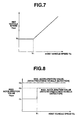
- step S23 set vehicle speed V SET is map-retrieved on the basis of host vehicle speed Vs from a predetermined or preprogrammed host-vehicle speed versus set-vehicle-speed characteristic map showing how set vehicle speed V SET varies relative to host vehicle speed Vs.
- step S24 adaptive vehicle-speed-control initiation indicative flag FS is reset to "0".
- a speed value denoted by V 1 is a low-speed threshold value preset at a predetermined value higher than the maximum speed value of a creep speed (given during creeping travel of the host vehicle) occurring owing to a creep phenomenon of the automatic transmission 3.
- step S25 occurs when host vehicle speed Vs is above the low-speed threshold value V 1 . That is, when host vehicle speed Vs is above the low-speed threshold value V 1 , it is possible to maintain set vehicle speed V SET without producing any braking force.
- set vehicle speed V SET is fixed to or maintained at low-speed threshold value V 1 .
- set vehicle speed V SET increases in direct-proportion to an increase in host vehicle speed Vs.
- step S25 occurs.
- step S25 a sum (V SET + ⁇ Vs), obtained by adding a predetermined value ⁇ Vs to the current value of set vehicle speed V SET , is set as a new set vehicle speed V SET . Then, step S26 occurs. At step S26, a test is made to determine whether set vehicle speed V SET exceeds an upper limit V SMAX of set vehicle speed. In case of V SET > V SMAX , the routine proceeds from step S26 to step S27. At step S27, set vehicle speed V SET is limited to upper limit V SMAX .
- step S26 when the answer to step S26 is negative (NO), that is, in case of V SET ⁇ V SMAX , the set-vehicle-speed (V SET ) setting subroutine terminates.
- step S21 negative (NO)
- step S28 a check is made to determine whether resume switch 20 is turned on.
- step S28 is negative (NO)
- resume switch 20 is turned off
- step S29 occurs.
- step S29 a check is made to determine whether the adaptive vehicle-speed-control initiation indicative flag is set.
- FS 1
- the routine flows from step S29 to step S30.
- step S30 a set vehicle speed V SET ' set just before cancellation of the adaptive vehicle speed control is set as set vehicle speed V SET .
- step S31 adaptive vehicle-speed-control initiation indicative flag FS is reset to "0".
- step S32 occurs.
- step S32 the difference (V SET - ⁇ Vs), obtained by subtracting predetermined value ⁇ Vs to the current value of set vehicle speed V SET , is set as a new set vehicle speed V SET .
- step S33 a test is made to determine whether set vehicle speed V SET is less than predetermined low-speed threshold value V 1 . In case of V SET ⁇ V 1 , the routine ends. Conversely, in case of V SET ⁇ V 1 , the routine proceeds from step S33 to step S34.
- predetermined low-speed threshold value V 1 is set as set vehicle speed V SET . In this manner, one cycle of the routine terminates.
- step S41 a check is made to determine whether inter-vehicle distance sensor 12 captures or detects the preceding vehicle (the relevant target vehicle).
- step S42 occurs.
- step S42 a check is made to determine whether the host vehicle speed Vs is below the predetermined low-speed threshold value V 1 .
- Vs ⁇ V 1 the routine proceeds from step S42 to step S43.
- step S43 maximum acceleration value ⁇ MAX is set at a first set value ⁇ 1 (a comparatively small acceleration value).
- step S44 the routine proceeds from step S42 to step S44.
- step S44 the maximum acceleration value ⁇ MAX is set at a second set value ⁇ 2 (greater than first set value ⁇ 1 ).
- step S45 maximum acceleration value ⁇ MAX is set at a third set value ⁇ 3 (greater than second set value ⁇ 2 ).
- FIG. 6 there is shown the desired acceleration-and-deceleration (G*) arithmetic calculation routine.
- a desired acceleration/deceleration G* V used for vehicle speed control (mainly in absence of preceding vehicle detection) is arithmetically calculated from the following expression (1).
- G* V (K P + K I /s + K D ⁇ s)Ve
- s denotes a Laplace variable
- K P , K I , and K D respectively denote a proportional gain, an integral gain, and a derivative gain
- Ve is the speed deviation calculated at step S51.
- step S53 a check is made to determine whether the inter-vehicle distance sensor 12 captures or detects the preceding vehicle (the relevant target vehicle). If the inter-vehicle distance sensor 12 does not detect the preceding vehicle, the routine jumps from step S53 to step S58 which will be fully described later. When the inter-vehicle distance sensor 12 detects the preceding vehicle, the routine proceeds from step S53 to step S54. At step S54, a desired inter-vehicle distance L* is arithmetically calculated from the following expression (2).
- L* Vs ⁇ t 0 + L S
- L 0 a time-to-reaching to predetermined inter-vehicle-distance
- L S denotes an offset value from a vehicle in front, required when the host vehicle is stopped.
- a relative speed ⁇ V of the preceding vehicle with respect to the host vehicle is computed by differentiating the detected inter-vehicle distance L by way of a band-pass filtering process or a high-pass filtering process, and then defined as (dL/dt)L.
- step S58 a check is made to determine whether inter-vehicle distance sensor 12 captures or detects the preceding vehicle (the relevant target vehicle).
- the routine flows from step S58 to step S59.
- desired acceleration/deceleration G* V used for vehicle speed control and calculated through step S52 is set as a desired acceleration/deceleration G*, and then the routine advances to step S61 (described later).
- step S58 when inter-vehicle distance sensor 12 detects the preceding vehicle, the routine proceeds from step S58 to step S60.
- step 560 the lowest one of the desired acceleration/deceleration G* V calculated at step S52 and desired acceleration/deceleration G* L calculated at step S57 is set as the desired acceleration/deceleration by way of a so-called select-LOW process. Thereafter, the routine shifts to step S61.
- step S61 a test is made to determine whether desired acceleration/deceleration G* selected through steps S59 or S60 is greater than the maximum acceleration value ⁇ MAX . In case of G* > ⁇ MAX , step S62 occurs.
- maximum acceleration value ⁇ MAX is set as desired acceleration/deceleration G*.
- the program exits the routine.
- the adaptive vehicle speed control system operates as follows.
- the adaptive vehicle speed control is disengaged or released, that is to say, adaptive vehicle-speed-control indicative flag FC is reset, and additionally the host vehicle is now stopped and separated from the preceding vehicle predetermined offset value L S .
- the program proceeds from step S1 to step S2, and thus ends not via steps S3 or S6.
- the system does not execute the adaptive vehicle-speed-control subroutine (or the following-control subroutine) shown in Fig. 3 and related to steps S3 and S6.
- the adaptive vehicle-speed-control function is continuously disengaged or released.
- step S3 adaptive vehicle-speed-control indicative flag FC is set at "1", and simultaneously adaptive vehicle-speed-control initiation indicative flag FS is set at "1".
- step S4 adaptive vehicle-speed-control indicative flag FC is set at "1"
- step S4 adaptive vehicle-speed-control indicative flag FS is set at "1"
- the adaptive vehicle-speed-control routine initiates.
- the host vehicle speed Vs is calculated through step S11 of Fig. 3, and then the host vehicle's distance L from the preceding vehicle, detected by sensor 12, is read out (see step S12). Thereafter, the set-vehicle-speed (V SET ) setting subroutine shown in Fig.
- step 523 set vehicle speed V SET is determined or map-retrieved based on host vehicle speed Vs from the preprogrammed host-vehicle speed versus set-vehicle-speed characteristic map shown in Fig. 7. At this time, the host vehicle is still stopped and thus the host vehicle speed Vs is zero.
- step S24 the adaptive vehicle-speed-control initiation indicative flag FS is reset to "0" .
- the routine proceeds from step S13 to step S14.
- maximum acceleration value ⁇ MAX the system executes maximum acceleration value ( ⁇ MAX ) setting subroutine shown in Fig. 5.
- the preceding vehicle has already been recognized, captured,or detected by inter-vehicle distance sensor 12, and thus the routine flows from step S41 to step S45.
- the maximum acceleration value ⁇ MAX is set at the third set value ⁇ 3 (> ⁇ 2 > ⁇ 1 ) (see the uppermost horizontal line shown in Fig. 8).
- step S15 desired acceleration-and-deceleration (G*) arithmetic calculation processing of Fig. 6 is executed.
- Vehicle speed deviation Ve is calculated through step S51 of Fig. 6.
- step S52 the routine proceeds from step S52 via step S53 to step S54, since inter-vehicle distance sensor 12 continues to detect or recognize the preceding vehicle.
- the host vehicle speed Vs is still kept at "0", and thus desired inter-vehicle distance L* becomes the offset value L S through step S54.
- the actual inter-vehicle distance L is L S .
- step S58 the routine proceeds from step S57 via step S58 to step S60.
- step S16 throttle opening ⁇ of the throttle valve is set at "0", that is, the throttle valve is adjusted to its fully-closed position, due to desired acceleration/deceleration G* set at "0".
- step S16 throttle opening ⁇ of the throttle valve is set at "0"
- P B * a command signal representative of a predetermined target braking pressure P B * is continuously output to the hydraulic modulator included in brake control system 8, in order to maintain a braking condition (or a stopped state of the vehicle).
- maximum acceleration value ⁇ MAX is set at the third set value ⁇ 3 (the highest one of the three different set values ⁇ 1 , ⁇ 2 , and ⁇ 3 ) (see the uppermost horizontal line of Fig. 8), so as to allow the host vehicle to be accelerated at a high acceleration rate suitable for the acceleration rate of the preceding vehicle.
- This provides the improved acceleration performance and insures a smooth comfortable acceleration of the vehicle without giving the driver uncomfortable feel.
- low-speed threshold value V 1 is set as set vehicle speed V SET .
- low-speed threshold value V 1 is predetermined as a vehicle speed value that can maintain a set vehicle speed V SET with no assistance of a braking force.
- the system can maintain set vehicle speed V SET through only the adaptive vehicle-speed-control system actuated vehicle acceleration, but not through the adaptive vehicle-speed-control system actuated vehicle deceleration. After this, as soon as host vehicle speed Vs reaches set vehicle speed V SET . host vehicle speed Vs is kept at set vehicle speed V SET .
- step S22 With host vehicle speed Vs kept at set vehicle speed V SET , when the driver newly switches the set switch 18 on, the routine proceeds from step S22 to step 525, since adaptive vehicle-speed-control initiation indicative flag FS is reset to "0" through set vehicle speed V SET setting subroutine shown in Fig. 4. As a result, the current set vehicle speed V SET is incremented by the predetermined speed value ⁇ Vs at one control cycle. Therefore, if the driver continues the ON state of the set switch 18, set vehicle speed V SET can be increased responsively to a time duration during which the set switch is continuously turned on.
- set vehicle speed V SET is limited to upper limit V SMAX (see step S27 of Fig. 4).
- the host vehicle speed Vs also increases in a manner such that the host vehicle satisfactorily follows the preceding vehicle.
- step S21 the routine proceeds from step S21 via step S28 to step S29, and then advances to step S32, since adaptive vehicle-speed-control initiation indicative flag FS has already been reset. Thereafter, the current set vehicle speed V SET is decremented by predetermined speed value ⁇ Vs at one control cycle .
- set vehicle speed V SET can be decreased responsively to a time duration during which the resume switch is continuously switched on.
- set vehicle speed V SET becomes less than the predetermined low-speed threshold value V 1
- set vehicle speed V SET is limited to low-speed threshold value V 1 (see the flow from step S33 to step S34 of Fig. 4).
- the system operating mode is quickly shifted to the previously-described following control mode, even in case that set switch 18 is turned on under a specified condition where inter-vehicle distance sensor 12 detects the preceding vehicle and the host vehicle is running at an excessively low speed just after starting.
- low-speed threshold value V 1 is set as set vehicle speed V SET
- maximum acceleration value ⁇ MAX is set at the third set value ⁇ 3 .
- desired acceleration/deceleration value G* is set at a negative value. That is, the desired deceleration rate for the host vehicle is calculated through the arithmetic processing of Fig. 6.
- desired braking pressure P B * the system maintains the automatic stop mode as long as the preceding vehicle is stopped.
- set vehicle speed V SET is set at the low-speed threshold value V 1 .
- maximum acceleration value ⁇ MAX is set to the first set value ⁇ 1 corresponding to the lowest one of three different set values ⁇ 1 , ⁇ 2 , and ⁇ 3 (see the flow from step S41 via step S42 to step S43 in the flow chart shown in Fig. 5). In this case, in the arithmetic calculation processing of Fig.
- Positive large value G* V is set as desired acceleration/deceleration value G* (see the flow from step S52 through steps S53 and S58 to step S59).
- maximum acceleration value ⁇ MAX is set the lowest set value ⁇ 1 , and as a result of this the desired acceleration/deceleration G* is limited to the first set value ⁇ 1 (see the flow from step S61 to step S62 and simultaneously see the lowermost acceleration limiting horizontal line ( ⁇ 1 ) of Fig. 8 with no relevant target detection).
- a command signal indicative of a throttle opening ⁇ based on desired acceleration/deceleration value G* (limited to the first set value ⁇ 1 ) is output to the throttle actuator incorporated in engine output control system 9.
- G* desired acceleration/deceleration value
- V 1 low-speed threshold value
- maximum acceleration value ⁇ MAX is set at the second set value ⁇ 2 (the second highest set value) greater than the first set value ⁇ 1 (see the flow from step S41 via step S42 to step S44 and simultaneously see intermediate acceleration limiting horizontal line ( ⁇ 2 ) of Fig. 8 with no relevant target detection).
- the host vehicle can be accelerated in a manner such that host vehicle speed Vs is brought closer to a new set vehicle speed V SET at a middle acceleration rate based on the second set value ⁇ 2 .
- the previously-discussed adaptive vehicle speed control function is turned off, when the ACC control cancellation condition is met .
- adaptive vehicle speed control suppose the host vehicle is following the preceding vehicle with preceding vehicle detection, or running at a constant-speed running mode in such a manner as to maintain a set vehicle speed V SET with no preceding vehicle detection, or stopped in the automatic stop mode. Under such a condition, when accelerator pedal 14 is depressed by the driver and thus accelerator switch 15 is switched on, or when brake pedal 16 is depressed by the driver and thus brake switch 17 is switched on, or when the driver switches cancel switch 19 on, the adaptive vehicle speed control function is deactivated or disengaged. As set out above, if the ACC control cancellation condition is met, in the adaptive vehicle-speed-control management processing of Fig.
- step S2 the program proceeds from step S1 through step S5 to step S6 so as to suspend the adaptive vehicle speed control subroutine (the following-control subroutine) shown in Fig. 3 and consequently to deactivate or disengage the adaptive vehicle speed control function, and then advances to step S7 so as to reset adaptive vehicle-speed-control indicative flag FC.
- Reactivation of the adaptive vehicle speed control function is only possible when the driver switches the set switch 18 on again. With the adaptive vehicle speed control system disengaged, the host vehicle is accelerated or decelerated by operating the accelerator pedal 14 or the brake pedal 16 by the driver.
- set vehicle speed V SET is set at the previously-noted low-speed threshold value V 1 that can maintain the set adaptive vehicle speed control speed with no assistance of a braking force, but not at a vehicle road speed the host vehicle was traveling at when the set switch was turned on.
- V 1 the previously-noted low-speed threshold value
- the system of the embodiment can prevent an undesired control action that the set vehicle speed is maintained while applying the disk brakes by means of brake control system 8.
- the set vehicle speed V SET is set at the predetermined low-speed threshold value V 1 higher than a creeping speed of the host vehicle creeping. This reduces a frequency of alterations to the set vehicle speed.
- maximum acceleration value ⁇ MAX is set to the first set value ⁇ 1 (a low acceleration limiting value), thus preventing rapid acceleration and insuring smooth comfortable acceleration.
- maximum acceleration value ⁇ MAX is set to the second set value ⁇ 2 (a middle acceleration limiting value).
- the system of the embodiment allows the host vehicle to accelerate at an adequate acceleration rate. Furthermore, in presence of preceding vehicle detection, regardless of whether the host vehicle speed Vs is high or low, the maximum acceleration value ⁇ MAX is set to the third set value ⁇ 3 (a middle acceleration limiting value). Thus, the system allows the host vehicle to rapidly accelerate at a high acceleration rate in response to the accelerating state of the preceding vehicle.
- set vehicle speed V SET is actually map-retrieved from the preprogrammed characteristic map shown in Fig. 7.
- the way to determine set vehicle speed V SET is not limited to such a map-retrieval.
- a way to set the set vehicle speed V SET may be comprised of (a) determining whether host vehicle speed Vs is below low-speed threshold value V 1 , (b) setting low-speed threshold value V 1 as set vehicle speed V SET when Vs ⁇ V 1 , and (c) setting host vehicle speed Vs as the set vehicle speed V SET when Vs > V 1 .
- low-speed threshold value V 1 is preset at a predetermined value greater than the maximum creeping speed occurring owing to a creep phenomenon of the automatic transmission.
- low-speed threshold value V 1 may be preset at a speed value higher than a speed at which low threshold road speed V 1 can be maintained with no need of a braking force, or at a speed value higher than a speed at which the vehicle can run without any throttle opening (with the throttle valve kept at a minimum throttle opening substantially corresponding to a substantially closed position of the throttle valve) and without any braking force.
- a scanning laser radar is used as the inter-vehicle distance sensor 12 which detects a relevant target vehicle .
- other object-detection technologies may be used for relevant target vehicle detection.
- a millimeter-wave radar sensor may be used for target vehicle detection.
- image-processing image data of a stereocamera using a charge-coupled device (CCD) image sensor the system is able to determine a host vehicle's distance from the preceding vehicle.
- a typical automatic transmission 3 which permits a creeping travel of the vehicle without depression of the accelerator in a low vehicle speed range, is mated to the output side of an internal combustion engine 2.
- the typical automatic transmission 3 may be replaced by a belt-type continuously variable transmission (CVT) or a toroidal CVT. That is, the fundamental concept of the invention can be applied to an automotive vehicle equipped with an engine mated to a CVT. Also, in the shown embodiment, by controlling wheel-brake cylinder pressure of each of disc brakes 7, the system is able to produce a controlled braking force or a controlled braking torque.
- the fundamental concept of the invention can be applied to an electric vehicle or an automotive vehicle employing a parallel hybrid system in which an electric motor generator is used as an actuator of the brake control system instead of the hydraulically-operated disk brakes, and the motor generator can regenerates electricity to the car battery to produce a regenerative braking effect .
- the adaptive vehicle speed control system requires an electric motor generator control system instead of the engine output control system 9.
- the adaptive vehicle speed control system of the invention is exemplified in a rear-wheel drive vehicle, it will be appreciated that the fundamental concept of the invention can be applied to a four-wheel drive vehicle or to a front-wheel drive vehicle.
Landscapes
- Engineering & Computer Science (AREA)
- Chemical & Material Sciences (AREA)
- Combustion & Propulsion (AREA)
- Transportation (AREA)
- Mechanical Engineering (AREA)
- Controls For Constant Speed Travelling (AREA)
- Control Of Driving Devices And Active Controlling Of Vehicle (AREA)
- Control Of Vehicle Engines Or Engines For Specific Uses (AREA)
Claims (9)
- Adaptives Fahrzeuggeschwindigkeits-Steuersystem, welches eine Maschinendrehmomentsteuerung und eine Bremssteuerung bewirkt, umfassend:dadurch gekennzeichnet, dasseine Geschwindigkeitserfassungseinrichtung (13), die eine Fahrzeuggeschwindigkeit (Vs) eines Hostfahrzeugs erfasst, das einer adaptiven Fahrzeuggeschwindigkeitssteuerung ausgesetzt ist, die eine Folgesteuerung eines vorausfahrenden Fahrzeugs und eine Fahrzeuggeschwindigkeitssteuerung einschließt;eine Abstandserfassungseinrichtung (12), die einen Fahrzeugzwischenabstand (L) zwischen dem Hostfahrzeug und einem vorausfahrenden Fahrzeug erfasst;eine Geschwindigkeitssetzeinrichtung, mit einer Mensch-Maschine-Schnittstelle (18-20), die eine gesetzte Fahrzeuggeschwindigkeit (VSET) setzt;einen Fahrzeuggeschwindigkeitscontroller (30) mit:einem Arithmetik-Verarbeitungsabschnitt, der einen gewünschten Fahrzeugzwischenabstand (L*) auf Grundlage wenigstens der Hostfabrzeuggeschwindigkeit (Vs) berechnet; undeinem Folgesteuerabschnitt, der eine gewünschte Geschwindigkeit auf Grundlage der Hostfahrzeuggeschwindigkeit (Vs) und des Fahrzeugzwischenabstands (L) bestimmt, so dass der Fahrzeugzwischenabstand bei Anwesenheit einer Erfassung eines vorausfahrenden Fahrzeugs näher auf den gewünschten Fahrzeugzwischenabstand (L*) gebracht wird;eine Einstelleinrichtung (8, 9), die die Hostfahrzeuggeschwindigkeit (Vs) auf die gewünschte Geschwindigkeit einstellt, die von dem Fahrzeuggeschwindigkeitscontroller (30) bestimmt wird; undeine Initiierungsbefehlseinrichtung, die ein Befehlssignal ausgibt, das eine Initiierung einer adaptiven Fahrzeuggeschwindigkeitssteuerung, einschließlich einer Folgesteuerung, die durch die Folgesteuerabschnitt ausgeführt wird, und einer Fahrzeuggeschwindigkeitssteuerung, die durch einen Fahrzeuggeschwindigkeitssteuerabschnitt ausgeführt wird, anzeigt;
der Fahrzeuggeschwindigkeitscontroller (30) einen Setzabschnitt einschließt, der die gewünschte Geschwindigkeit, die von dem Fahrzeuggeschwindigkeitscontroller bestimmt wird, auf einen Geschwindigkeitswert höher als einen Niedergeschwindigkeits-Schwellwert (V1), bei Anwesenheit einer Ausgabe des Befehlssignals bei einer spezifizierten Bedingung, bei der die Hostfahrzeuggeschwindigkeit (Vs) unter dem Niedergeschwindigkeits-Schwellwert (V1) ist, setzt. - System nach Anspruch 1, wobei der Fahrzeuggeschwindigkeitscontroller (30) einen Beschleunigungssetrabschnitt einschließt, der einen maximalen Wert einer Beschleunigung, die von sowohl dem Folgesteuerabschnitt als auch dem Fahrzeuggeschwindigkeitssteuerabschnitt zugelassen wird, auf einen ersten Setzwert bei Anwesenheit einer Ausgabe des Befehlssignals bei der spezifizierten Bedingung, bei der die Hostfahrzeuggeschwindigkeit (Vs) unter dem Niedergeschwindigkeits-Schwellwert (V1) ist, setzt und den maximalen Wert der Beschleunigung auf einen zweiten Wert, höher als der erste, setzt, wenn die gesetzte Fahrzeuggeschwindigkeit, die von der Mensch-Maschine-Schnittstelle gesetzt wird, den Niedergeschwindigkeits-Schwellwert (V1) übersteigt.
- System nach Anspruch 1 oder 2, mit einem Automatikgetriebe, das eine Kriechbewegung des Hostfahrzeugs ohne Niederdrücken eines Gaspedals in einem Niedergeschwindigkeitsbereich erlaubt, wobei der Niedergeschwindigkeits-Schwellwert (V1) auf einen Geschwindigkeitswert höher als eine Kriechgeschwindigkeit während der Kriechbewegung gesetzt wird.
- System nach Anspruch 1 oder 2, wobei der Niedergeschwindigkeits-Schwellwert (V1) auf einen Geschwindigkeitswert höher als eine Geschwindigkeit gesetzt wird, bei der der Niedergeschwindigkeits-Schwellwert ohne die Notwendigkeit einer Bremskraft beibehalten wird.
- System nach Anspruch 1 oder 2, wobei der Niedergeschwindigkeits-Schwellwert (V1) auf einen Geschwindigkeitswert höher als eine Geschwindigkeit gesetzt wird, bei der das Hostfahrzeug ohne eine Drosselöffnung und ohne eine Bremskraft fährt.
- System nach Anspruch 2, wobei der Beschleunigungssetzabschnitt den maximalen Wert der Beschleunigung auf einen dritten gesetzten Wert, höher als der zweite, bei Anwesenheit einer Erfassung eines vorausfahrenden Fahrzeugs, setzt.
- System nach Anspruch 2, wobei der Fahrzeuggeschwindigkeitscontroller (30) einen Beschleunigungs-und-Verzögerungs-Setzabschnitt einschließt, der programmiert ist, um Folgendes auszuführen:(a) Berechnen einer Geschwindigkeitsabweichung (Ve) als eine Differenz zwischen der gesetzten Fahrzeuggeschwindigkeit (Vset) und der Hostfahrzeuggeschwindigkeit (Vs);(b) Berechnen eines ersten Beschleunigungs-und-Verzögerungswerts G*V, der für die Fahrzeuggeschwindigkeitssteuerung verwendet wird, aus einem ersten Ausdruck G*V = (KP + KI/s + KD's)Ve, wobei s eine Laplace-Variable bezeichnet, KP, KI und KD jeweils eine Proportional-Verstärkung, eine Integral-Verstärkung und eine Ableitungs-Verstärkung bezeichnen und Ve die Geschwindigkeitsabweichung ist;(c) Berechnen einer Fahrzeugzwischenabstandsabweichung (ΔL) als eine Differenz zwischen dem Fahrzeugzwischenabstand (L), der von der Abstandserfassungseinrichtung erfasst wird, und dem gewünschten Fahrzeugzwischenabstand (L*);(d) Berechnen einer relativen Geschwindigkeit (ΔV) des vorausfahrenden Fahrzeugs in Bezug auf das Hostfahrzeug, durch Differenzieren des erfassten Fahrzeugzwischenabstands (L);(e) Berechnen eines zweiten Beschleunigungs-und-Verzögerungswerts G*L, der für die Folgesteuerung verwendet wird, aus einem Ausdruck G*L = F1ΔL+ F2ΔV, wobei F1 und F2 Koeffizienten sind, ΔL die Fahrzeugzwischenabstandsabweichung bezeichnet, und ΔV die relative Geschwindigkeit bezeichnet;(f) Setzen des ersten Beschleunigungs-und-Verzögerungswerts G*V als den gewünschten Beschleunigungs-und-Verzögerungswert bei Anwesenheit einer Erfassung eines vorausfahrenden Fahrzeugs;(g) Setzen des niedrigeren der ersten und zweiten Beschleunigungs-und-Verzögerungswerte G*V und G*L als den gewünschten Beschleunigungs-und-Verzögerungswert bei Anwesenheit einer Erfassung eines vorausfahrenden Fahrzeugs;(h) Vergleichen des gewünschten Beschleumigungs-und-Verzögerungswerts mit dem maximalen Wert einer Beschleunigung; und(i) Begrenzen des gewünschten Beschleunigungs-und-Verzögerungswerts auf den maximalen Wert einen Beschleunigung, nur wenn der gewünschte Beschleunigungs-und-Verzögerungswert den maximalen Wert einer Beschleunigung übersteigt.
- System nach Anspruch 7, wobei die Fahrzeugbeschleunigung- und Verzögerung des Hostfahrzeugs durch eine Maschinendrehmomentsteuerung und eine Bremssteuerung eingestellt werden, in Abhängigkeit von dem gewünschten Beschlelmigungs-und-Verzögerungswert während der adaptiven Fahrzeuggeschwindigkeitssteuerung.
- Adaptives Fahrzeuggeschwindigkeitssteuerverfahren, welches eine Machinendrehmomentsteuerung und eine Bremssteuerung anwendet, umfassend die folgenden Schritte:Erfassen einer Fahrzeuggeschwindigkeit (Vs) eines Hostfahrzeug, das einer adaptiven Fahrzeuggeschwindigkeitssteuerung ausgesetzt ist, die eine Folgesteuerung eines vorausfahrenden Fahrzeugs und eine Fahrzeuggeschwindigkeitssteuerung einschließt;Erfassen eines Fahrzeugzwischenabstands (L) zwischen dem Hostfahrzeug und einem vorausfahrenden Fahrzeug;Setzen, durch eine Mensch-Maschine-Schnittstelle (18-20), einer gesetzten Fahrzeuggeschwindigkeit (VSET);Berechnen eines gewünschten Fahrzeugzwischenabstands (L*) auf Grundlage wenigstens der Hostfahrzeuggeschwindigkeit (Vs); undBestimmen einer gewünschten Geschwindigkeit des Hostfahrzeugs auf Grundlage der Hostfahrzeuggeschwindigkeit (Vs) und des Fahrzeugzwischenabstands (L), so dass der Fahrzeugzwischenabstand (L) bei Anwesenheit einer Erfassung eines vorausfahrenden Fahrzeugs näher auf den gewünschten Fahrzeugzwischenabstand (L*) gebracht wird;Einstellen der Hostfahrzeuggeschwindigkeit (Vs) auf die gewünschte Geschwindigkeit;Ausgeben eines Befehlssignals, das eine Initiierung einer adaptiven Fahrzeuggeschwindigkeitssteuerung, einschließlich der Folgesteuerung und der Fahrzeuggeschwindigkeitssteuerung, anzeigt; undSetzen der gewünschten Geschwindigkeit auf einen Geschwindigkeitswert höher als einen Niedergeschwindigkeits-Schwellwert (V1), bei Anwesenheit einer Ausgabe des Befehlssignals bei einer spezifizierten Bedingung, bei der die Hostfahrzeuggeschwindigkeit (Vs) unter dem Niedergeschwindigkeits-Schwellwert (V1) ist.
Applications Claiming Priority (2)
| Application Number | Priority Date | Filing Date | Title |
|---|---|---|---|
| JP21668999 | 1999-07-30 | ||
| JP21668999A JP3627582B2 (ja) | 1999-07-30 | 1999-07-30 | 車両用追従制御装置 |
Publications (3)
| Publication Number | Publication Date |
|---|---|
| EP1072458A2 EP1072458A2 (de) | 2001-01-31 |
| EP1072458A3 EP1072458A3 (de) | 2002-01-02 |
| EP1072458B1 true EP1072458B1 (de) | 2003-12-03 |
Family
ID=16692390
Family Applications (1)
| Application Number | Title | Priority Date | Filing Date |
|---|---|---|---|
| EP00306451A Expired - Lifetime EP1072458B1 (de) | 1999-07-30 | 2000-07-28 | Adaptive Steuerung der Geschwindigkeit eines Fahrzeugs |
Country Status (4)
| Country | Link |
|---|---|
| US (1) | US6339740B1 (de) |
| EP (1) | EP1072458B1 (de) |
| JP (1) | JP3627582B2 (de) |
| DE (1) | DE60006904T2 (de) |
Cited By (1)
| Publication number | Priority date | Publication date | Assignee | Title |
|---|---|---|---|---|
| DE102009045336A1 (de) | 2009-10-05 | 2011-04-07 | Ford Global Technologies, LLC, Dearborn | Verfahren und Vorrichtung zum Steuern des Betriebs eines Verbrennungsmotors |
Families Citing this family (44)
| Publication number | Priority date | Publication date | Assignee | Title |
|---|---|---|---|---|
| DE19960782A1 (de) * | 1999-12-16 | 2001-06-21 | Mannesmann Vdo Ag | Verfahren zur Beschleunigungsüberwachung für eine Längsdynamiksteuerung oder -regelung in Kraftfahrzeugen |
| JP3675281B2 (ja) * | 2000-02-15 | 2005-07-27 | 日産自動車株式会社 | 車両のエンジン自動停止再始動装置 |
| DE10023067A1 (de) * | 2000-05-11 | 2001-11-15 | Volkswagen Ag | Verfahren und Vorrichtung zur Regelung eines Andockvorganges zwischen zwei Kraftfahrzeugen |
| DE10037826A1 (de) * | 2000-08-03 | 2002-02-14 | Daimler Chrysler Ag | Verfahren und Einrichtung zur selbsttätigen Geschwindigkeitseinstellung in einem Fahrzeug |
| JP3909647B2 (ja) * | 2000-12-13 | 2007-04-25 | 本田技研工業株式会社 | オートクルーズ装置 |
| JP3800007B2 (ja) * | 2001-01-09 | 2006-07-19 | 日産自動車株式会社 | 制動制御装置 |
| JP3646660B2 (ja) * | 2001-03-26 | 2005-05-11 | 日産自動車株式会社 | 車両用追従走行制御装置 |
| JP3838048B2 (ja) * | 2001-04-16 | 2006-10-25 | 日産自動車株式会社 | 車両用走行制御装置 |
| JP4784007B2 (ja) * | 2001-06-28 | 2011-09-28 | トヨタ自動車株式会社 | 車両の運転支援装置 |
| JP2003231422A (ja) * | 2002-02-08 | 2003-08-19 | Hitachi Ltd | 車間距離自動制御装置および自動車 |
| JP3843898B2 (ja) * | 2002-06-21 | 2006-11-08 | トヨタ自動車株式会社 | 走行制御装置 |
| JP4039184B2 (ja) * | 2002-08-29 | 2008-01-30 | 株式会社アドヴィックス | クリープ走行制御装置 |
| US6842231B2 (en) * | 2002-09-30 | 2005-01-11 | Raytheon Company | Method for improved range accuracy in laser range finders |
| US6778897B2 (en) * | 2002-11-27 | 2004-08-17 | Visteon Global Technologies, Inc. | Adaptive cruise control system and strategy |
| DE10319337A1 (de) * | 2003-04-30 | 2004-11-18 | Robert Bosch Gmbh | Vorrichtung zur Geschwindigkeits- und Abstandsregelung bei Kraftfahrzeugen |
| JP3925488B2 (ja) * | 2003-11-11 | 2007-06-06 | 日産自動車株式会社 | 車両用画像処理装置 |
| JP4246084B2 (ja) * | 2004-02-17 | 2009-04-02 | 日産自動車株式会社 | 車両用走行制御装置 |
| US20050209762A1 (en) * | 2004-03-18 | 2005-09-22 | Ford Global Technologies, Llc | Method and apparatus for controlling a vehicle using an object detection system and brake-steer |
| JP4379184B2 (ja) * | 2004-04-08 | 2009-12-09 | 日産自動車株式会社 | 車両の制動制御装置 |
| DE102004048013A1 (de) * | 2004-10-01 | 2006-04-06 | Robert Bosch Gmbh | Verfahren und Vorrichtung zur Fahrerunterstützung |
| JP4525495B2 (ja) * | 2005-07-06 | 2010-08-18 | トヨタ自動車株式会社 | 車両用走行制御装置 |
| JP2007120416A (ja) * | 2005-10-28 | 2007-05-17 | Advics:Kk | 車両用自動制動装置 |
| US7756610B2 (en) * | 2005-12-08 | 2010-07-13 | Borgwarner, Inc. | Solenoid controller |
| DE102007005030A1 (de) * | 2007-02-01 | 2008-08-07 | Robert Bosch Gmbh | Verfahren für die Steuerung eines Fahrzeugs mit Hybridantrieb |
| JP4938542B2 (ja) * | 2007-04-27 | 2012-05-23 | トヨタ自動車株式会社 | 車両の車速制御装置 |
| JP4497231B2 (ja) * | 2007-10-09 | 2010-07-07 | 株式会社デンソー | 車両用速度制御装置 |
| DE102008014771A1 (de) * | 2008-03-18 | 2009-09-24 | Wabco Gmbh | Abstandregeltempomat |
| US7801512B1 (en) * | 2009-03-05 | 2010-09-21 | Makor Issues And Rights Ltd. | Traffic speed enforcement based on wireless phone network |
| US8380419B2 (en) * | 2009-03-27 | 2013-02-19 | Zf Friedrichshafen Ag | Resume speed adaptation for automatic vehicle acceleration at a rate derived from a measured acceleration rate |
| GB2483720B (en) | 2010-09-20 | 2017-10-25 | Jaguar Land Rover Ltd | Improvements relating to brake control |
| DE102011084606A1 (de) * | 2011-10-17 | 2013-04-18 | Robert Bosch Gmbh | Bestimmung einer Fahrstrategie für ein Fahrzeug |
| KR20140053701A (ko) * | 2012-10-26 | 2014-05-08 | 현대자동차주식회사 | E-4wd 하이브리드 전기자동차의 제어장치 및 방법 |
| JP5756822B2 (ja) * | 2013-03-27 | 2015-07-29 | 富士重工業株式会社 | ハイブリッド車両の発電制御装置 |
| DE102013207539A1 (de) * | 2013-04-25 | 2014-10-30 | Bayerische Motoren Werke Aktiengesellschaft | Geschwindigkeitsregelsystem für Kraftfahrzeuge |
| DE102013213050A1 (de) * | 2013-07-04 | 2015-01-08 | Conti Temic Microelectronic Gmbh | Accellerator Force Feedback Pedal (AFFP) als Assistenzsystem zur Abstandsregelung im Straßenverkehr |
| JP6075329B2 (ja) * | 2014-06-06 | 2017-02-08 | 株式会社デンソー | 車両制御装置および車両制御プログラム |
| US9977512B2 (en) * | 2014-10-24 | 2018-05-22 | Intersil Americas LLC | Open loop correction for optical proximity detectors |
| US10795005B2 (en) * | 2014-12-09 | 2020-10-06 | Intersil Americas LLC | Precision estimation for optical proximity detectors |
| JP6337865B2 (ja) * | 2015-10-16 | 2018-06-06 | トヨタ自動車株式会社 | 車両用停車制御装置 |
| US10183684B2 (en) * | 2016-03-31 | 2019-01-22 | General Electric Company | Multiple vehicle control system |
| US11046311B2 (en) | 2018-01-22 | 2021-06-29 | Nissan Motor Co., Ltd. | Vehicle control method and vehicle control device |
| KR102563005B1 (ko) * | 2018-12-07 | 2023-08-04 | 현대자동차주식회사 | 차량 및 그 제어 방법 |
| CN109866770A (zh) * | 2019-02-28 | 2019-06-11 | 重庆长安汽车股份有限公司 | 一种车辆自适应巡航控制方法、装置、系统及汽车 |
| JP7333230B2 (ja) * | 2019-09-11 | 2023-08-24 | 日産自動車株式会社 | 車両の制御方法及び車両の制御装置 |
Family Cites Families (9)
| Publication number | Priority date | Publication date | Assignee | Title |
|---|---|---|---|---|
| JPH06255389A (ja) * | 1991-02-26 | 1994-09-13 | Mitsubishi Electric Corp | 車両の走行制御装置 |
| JPH06320985A (ja) * | 1993-05-19 | 1994-11-22 | Mazda Motor Corp | 自動車速度制御装置 |
| GB9425057D0 (en) * | 1994-12-13 | 1995-02-08 | Lucas Ind Plc | Apparatus and method for cruise control |
| JP3237435B2 (ja) * | 1995-01-20 | 2001-12-10 | 三菱自動車工業株式会社 | 車両の走行制御装置 |
| JP3805832B2 (ja) * | 1996-07-10 | 2006-08-09 | 富士重工業株式会社 | 車両用運転支援装置 |
| DE19627727B4 (de) * | 1996-07-10 | 2012-05-31 | Robert Bosch Gmbh | Verfahren und Vorrichtung zur Steuerung der Geschwindigkeit eines Fahrzeugs |
| JP3930110B2 (ja) * | 1997-08-11 | 2007-06-13 | 富士重工業株式会社 | 車両のクルーズコントロール装置 |
| US6188950B1 (en) * | 1997-10-27 | 2001-02-13 | Nissan Motor Co., Ltd. | System and method for controlling inter-vehicle distance to preceding vehicle for automotive vehicle equipped with the system and method |
| JP3551756B2 (ja) * | 1998-04-06 | 2004-08-11 | 日産自動車株式会社 | 車両用走行制御装置 |
-
1999
- 1999-07-30 JP JP21668999A patent/JP3627582B2/ja not_active Expired - Lifetime
-
2000
- 2000-07-28 EP EP00306451A patent/EP1072458B1/de not_active Expired - Lifetime
- 2000-07-28 DE DE60006904T patent/DE60006904T2/de not_active Expired - Lifetime
- 2000-07-31 US US09/629,798 patent/US6339740B1/en not_active Expired - Lifetime
Cited By (1)
| Publication number | Priority date | Publication date | Assignee | Title |
|---|---|---|---|---|
| DE102009045336A1 (de) | 2009-10-05 | 2011-04-07 | Ford Global Technologies, LLC, Dearborn | Verfahren und Vorrichtung zum Steuern des Betriebs eines Verbrennungsmotors |
Also Published As
| Publication number | Publication date |
|---|---|
| DE60006904T2 (de) | 2004-10-28 |
| DE60006904D1 (de) | 2004-01-15 |
| US6339740B1 (en) | 2002-01-15 |
| EP1072458A3 (de) | 2002-01-02 |
| JP3627582B2 (ja) | 2005-03-09 |
| JP2001039181A (ja) | 2001-02-13 |
| EP1072458A2 (de) | 2001-01-31 |
Similar Documents
| Publication | Publication Date | Title |
|---|---|---|
| EP1072458B1 (de) | Adaptive Steuerung der Geschwindigkeit eines Fahrzeugs | |
| JP3675240B2 (ja) | 車両用追従制御装置 | |
| JP3478107B2 (ja) | 車両用走行制御装置 | |
| US6810319B2 (en) | Vehicle to vehicle distance controller and vehicle | |
| US6470257B1 (en) | Adaptive cruise control system for automotive vehicles | |
| US5215159A (en) | System for controlling a driving device of a vehicle | |
| US6665603B2 (en) | Vehicle traveling control system | |
| JP3127351B2 (ja) | 車両用オートクルーズ装置 | |
| US6687595B2 (en) | Adaptive cruise control system for vehicle | |
| US7002452B2 (en) | Collision preventing apparatus for a vehicle | |
| US6330508B1 (en) | Preceding vehicle following control system | |
| EP0949108B1 (de) | Abstandsbezogenes Fahrgeschwindigkeitsregelsystem | |
| JP3572978B2 (ja) | 車両用走行制御装置 | |
| US5765657A (en) | Traction control system for automotive vehicles | |
| JPH11278096A (ja) | 車両用走行制御装置 | |
| US6429788B2 (en) | Alarming apparatus and method for automotive vehicle | |
| US11932247B2 (en) | Driving assistance control device of vehicle having vehicle speed and acceleration control based on preceding vehicle information and road topology | |
| JP2001113979A (ja) | 車両間距離および車両速度の制御方法ならびに制御システム | |
| JP4696409B2 (ja) | 車両の運転操作支援装置 | |
| JP2001030794A (ja) | 車両用走行制御装置 | |
| JP3885347B2 (ja) | 車両用走行制御装置 | |
| JP2014152801A (ja) | 車両の走行制御装置 | |
| JP2000313245A (ja) | 車両用走行制御装置 | |
| JP2004161175A (ja) | 走行速度制御装置 | |
| JP2001138880A (ja) | 車両用制動制御装置 |
Legal Events
| Date | Code | Title | Description |
|---|---|---|---|
| PUAI | Public reference made under article 153(3) epc to a published international application that has entered the european phase |
Free format text: ORIGINAL CODE: 0009012 |
|
| 17P | Request for examination filed |
Effective date: 20000825 |
|
| AK | Designated contracting states |
Kind code of ref document: A2 Designated state(s): AT BE CH CY DE DK ES FI FR GB GR IE IT LI LU MC NL PT SE Kind code of ref document: A2 Designated state(s): DE FR GB |
|
| AX | Request for extension of the european patent |
Free format text: AL;LT;LV;MK;RO;SI |
|
| PUAL | Search report despatched |
Free format text: ORIGINAL CODE: 0009013 |
|
| AK | Designated contracting states |
Kind code of ref document: A3 Designated state(s): AT BE CH CY DE DK ES FI FR GB GR IE IT LI LU MC NL PT SE |
|
| AX | Request for extension of the european patent |
Free format text: AL;LT;LV;MK;RO;SI |
|
| RIN1 | Information on inventor provided before grant (corrected) |
Inventor name: KOBAYASHI, YOSUKE Inventor name: INOUE, HIDEAKI Inventor name: SETO, YOJI |
|
| AKX | Designation fees paid |
Free format text: DE FR GB |
|
| 17Q | First examination report despatched |
Effective date: 20030206 |
|
| GRAH | Despatch of communication of intention to grant a patent |
Free format text: ORIGINAL CODE: EPIDOS IGRA |
|
| GRAS | Grant fee paid |
Free format text: ORIGINAL CODE: EPIDOSNIGR3 |
|
| GRAA | (expected) grant |
Free format text: ORIGINAL CODE: 0009210 |
|
| AK | Designated contracting states |
Kind code of ref document: B1 Designated state(s): DE FR GB |
|
| PG25 | Lapsed in a contracting state [announced via postgrant information from national office to epo] |
Ref country code: FR Free format text: LAPSE BECAUSE OF FAILURE TO SUBMIT A TRANSLATION OF THE DESCRIPTION OR TO PAY THE FEE WITHIN THE PRESCRIBED TIME-LIMIT Effective date: 20031203 |
|
| REG | Reference to a national code |
Ref country code: GB Ref legal event code: FG4D |
|
| REG | Reference to a national code |
Ref country code: IE Ref legal event code: FG4D |
|
| REF | Corresponds to: |
Ref document number: 60006904 Country of ref document: DE Date of ref document: 20040115 Kind code of ref document: P |
|
| PLBE | No opposition filed within time limit |
Free format text: ORIGINAL CODE: 0009261 |
|
| STAA | Information on the status of an ep patent application or granted ep patent |
Free format text: STATUS: NO OPPOSITION FILED WITHIN TIME LIMIT |
|
| 26N | No opposition filed |
Effective date: 20040906 |
|
| EN | Fr: translation not filed | ||
| REG | Reference to a national code |
Ref country code: IE Ref legal event code: MM4A |
|
| PGFP | Annual fee paid to national office [announced via postgrant information from national office to epo] |
Ref country code: DE Payment date: 20190716 Year of fee payment: 20 |
|
| PGFP | Annual fee paid to national office [announced via postgrant information from national office to epo] |
Ref country code: GB Payment date: 20190724 Year of fee payment: 20 |
|
| REG | Reference to a national code |
Ref country code: DE Ref legal event code: R071 Ref document number: 60006904 Country of ref document: DE |
|
| REG | Reference to a national code |
Ref country code: GB Ref legal event code: PE20 Expiry date: 20200727 |
|
| PG25 | Lapsed in a contracting state [announced via postgrant information from national office to epo] |
Ref country code: GB Free format text: LAPSE BECAUSE OF EXPIRATION OF PROTECTION Effective date: 20200727 |