EP0933207A1 - Verfahren und Vorrichtung zur registergenauen Vorpositionierung einer Druckplatte - Google Patents
Verfahren und Vorrichtung zur registergenauen Vorpositionierung einer Druckplatte Download PDFInfo
- Publication number
- EP0933207A1 EP0933207A1 EP98123530A EP98123530A EP0933207A1 EP 0933207 A1 EP0933207 A1 EP 0933207A1 EP 98123530 A EP98123530 A EP 98123530A EP 98123530 A EP98123530 A EP 98123530A EP 0933207 A1 EP0933207 A1 EP 0933207A1
- Authority
- EP
- European Patent Office
- Prior art keywords
- plate
- positioning
- register
- prepositioning
- sensor means
- Prior art date
- Legal status (The legal status is an assumption and is not a legal conclusion. Google has not performed a legal analysis and makes no representation as to the accuracy of the status listed.)
- Granted
Links
Images


Classifications
-
- B—PERFORMING OPERATIONS; TRANSPORTING
- B41—PRINTING; LINING MACHINES; TYPEWRITERS; STAMPS
- B41F—PRINTING MACHINES OR PRESSES
- B41F27/00—Devices for attaching printing elements or formes to supports
- B41F27/12—Devices for attaching printing elements or formes to supports for attaching flexible printing formes
-
- B—PERFORMING OPERATIONS; TRANSPORTING
- B41—PRINTING; LINING MACHINES; TYPEWRITERS; STAMPS
- B41P—INDEXING SCHEME RELATING TO PRINTING, LINING MACHINES, TYPEWRITERS, AND TO STAMPS
- B41P2227/00—Mounting or handling printing plates; Forming printing surfaces in situ
- B41P2227/30—Detecting the correct position of printing plates on the cylinder
-
- Y—GENERAL TAGGING OF NEW TECHNOLOGICAL DEVELOPMENTS; GENERAL TAGGING OF CROSS-SECTIONAL TECHNOLOGIES SPANNING OVER SEVERAL SECTIONS OF THE IPC; TECHNICAL SUBJECTS COVERED BY FORMER USPC CROSS-REFERENCE ART COLLECTIONS [XRACs] AND DIGESTS
- Y10—TECHNICAL SUBJECTS COVERED BY FORMER USPC
- Y10S—TECHNICAL SUBJECTS COVERED BY FORMER USPC CROSS-REFERENCE ART COLLECTIONS [XRACs] AND DIGESTS
- Y10S101/00—Printing
- Y10S101/36—Means for registering or alignment of print plates on print press structure
Definitions
- the invention relates to a method for pre-positioning a register Printing plate in a plate feed device, wherein the printing plate through Positioning means of the plate feeder prepositioned and then the Plate cylinder fed and the same in the leading edge clamping device is clamped.
- the invention further relates to a device for carrying out the method a plate feed device which has at least two positioning pins which to pre-position a printing plate in recesses of the same and the can be disengaged, as well as means for transferring the prepositioned Pressure plate to the front edge clamping device of the plate cylinder.
- Such prepositioning of a printing plate is known from DE 195 08 844 A1 known.
- the plate feed device known from this document is not can be checked whether the pre-positioning has been carried out correctly and thus in register.
- a transport device provided on which suction cups are arranged, which are the prepositioned pressure plate to capture. Then the transport device, by pneumatic cylinder driven, the pressure plate in the front edge clamping device of the plate cylinder.
- This type of transfer of the pre-positioned printing plate to the Leading edge tensioning device is not only complex and expensive, but also too inaccurate to register the pre-positioned printing plate to the Hand over the leading edge clamping device of the plate cylinder.
- the invention is therefore based on the object that the method mentioned and the device mentioned at the outset are designed such that the control of the accurate positioning of the printing plate and the correction of the same as far as possible while the machine is running.
- the object is achieved in that the Precise register positioning of sensor means recorded and if necessary is corrected and then an accurate transfer to the Leading edge clamping device of the plate cylinder takes place.
- the object is achieved in that the Plate feed device sensor means for register-accurate registration Has prepositioning of the printing plate and the means for transferring the Pressure plate are designed in such a way that the register-accurate prepositioning is obtained remains.
- the printing plate is provided in register so that after the transfer of the pre-positioned printing plate to the plate cylinder usually only the fine adjustments still have to be made while the machine is at a standstill a test print is required anyway. Correcting the positioning of the Pressure plate after insertion into the leading edge tensioning device is in front of the It is usually no longer necessary to carry out a test print because of the Invention these corrections are moved to the printing plate feeder. On in this way, such corrections can already be made at a time when the Press still prints the previous job. In this way the Machine downtimes are shortened, increasing the machine's profitability.
- a particularly advantageous with regard to the register accuracy of the transfer Development of the method provides that the printing plates in the position of Precise pre-positioning can be held and the inclusion in the Front edge tensioning device is carried out by turning the plate cylinder backwards.
- An expedient embodiment provides that the register-accurate recording in the leading edge clamping device of the plate cylinder is detected by sensor means, to check the correctness of the delivery and, if necessary, a correction to be able to make. This way another check is done and it is possible that misadjustments and malfunctions even before a Sample prints can be noticed and corrected.
- the Means for transferring the printing plate arranged in the plate feed device Have holding means that detects the prepositioned printing plate that the Pre-positioning pins are equipped with drives that disengage them can be brought, and that the plate feeder is designed and is positionable that the pre-positioned and held pressure plate when removed Pre-positioning pins by turning the plate cylinder backwards into the Front edge tensioning device can be inserted.
- the Holding means is at least one suction cup.
- a further development provides that the leading edge tensioning device Positioning pins and sensor means for registering the exact positioning having. As already mentioned for the procedure, errors that occur can be detected immediately and be corrected in time.
- An embodiment for preventing the reverse use of a Pressure plate suggests that a pre-positioning pin and / or positioning pin and one Recess on one side of a printing plate leading edge compared to another Pre-positioning pin and / or positioning pin on the center line opposite side of the printing plate leading edge not interchangeable Have engagement positions. Leave these non-interchangeable engagement positions evolve in different ways, regarding the Design options are referred to the description of the figures.
- the sensor means electrical Contacts are the exact engagement of the prepositioning pins and / or Positioning pins in the recesses close a circuit, for example via the pressure plate.
- the Pre-positioning pins and / or positioning pins only in a partial area on their front Side are designed as electrical contacts. This ensures that it is too the electrical contact only comes when the positioning pins are completely in the Apply recesses.
- capacitive or inductive sensors can also be used as sensor means be used.
- plastic printing plates can be used optical sensors, ultrasonic sensors or microswitches can also be provided.
- FIG. 1 shows a possible arrangement of sensor means 8 and 9 for detecting the register-accurate pre-positioning of a printing plate 1 in a plate feed device 13 or also for registering the register-accurate positioning in the front edge clamping device 14 of a plate cylinder 2.
- prepositioning pins 3 and 4 or on positioning pins 3 'and 4' are electrical Contacts 18 arranged which when the pre-positioning pins 3, 4 or Positioning pins 3 ', 4' in recesses 5, 6 of a pressure plate 1 touch and thereby closing a circuit.
- the signal can be sent to an evaluation device 20 are given and a display device 21 indicates that the printing plate 1 is positioned exactly in register.
- the signal can of course also be sent to the Machine controls are given which, upon receipt, pave the way for further Approves procedural steps.
- FIG. 1 a shows a further embodiment, the prepositioning pins 3, 4 or positioning pins 3 ', 4' not yet having engaged in the recesses 5, 6 of the pressure plate 1.
- Both in FIG. 1 and in FIG. 1a are shapes of the prepositioning pins 3, 4 or the positioning pins 3 ', 4' and the recesses 5, 6 of the pressure plate 1 selected by which contact is only given when the pressure plate 1 is inserted correctly is possible.
- These different forms are expediently one
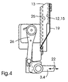
- FIG. 2 shows an exemplary embodiment of a plate feed device 13 and its interaction with the front edge clamping device 14 of a plate cylinder 2.
- pre-positioning pins 3, 4 are arranged which can be moved in the direction of the double arrows 22. As a result, they can be brought into an engagement position in which, as shown in FIG. 1, they engage in recesses 5 and 6 of a pressure plate 1.
- These prepositioning pins 3, 4 have sensor means 8 and 9, which are either designed as shown in FIGS. 1 and 1a or have another of the design options mentioned above.
- a printing plate 1 is inserted into the plate feed device 13 from above, then it is guided by guide means 12 and as long in the direction of arrow 10 inserted until the recesses 5 and 6 into the prepositioning pins 3 and 4 intervention.
- the sensor means 8 and 9 report the exact contact of the recesses 5 and 6 on the prepositioning pins 3 and 4, holding means 16 can take action.
- these are designed as suction cups 17, which are preferably spaced apart in the vertical direction.
- the Pressure plate 1 keeps exactly their pre-positioning, held by the suction cups 17 at.
- the pre-positioning pins 3 and 4 By arranging the pre-positioning pins 3 and 4 on the lower End of the plate feeder 13 and by the training and positioning the plate feeder 13, it is possible that the printing plate leading edge 7 of the front edge clamping device 14 of the plate cylinder 2 is received.
- the plate cylinder 2 rotates from the drawn position in the direction of the arrow 28 backwards until the pressure plate 1 is inserted into the front edge tensioning device 14.
- the positioning pins 3 'and 4' can repeated control of the positioning also equipped with sensor means 8, 9 be.
- the plate cylinder 2 After the insertion of the printing plate leading edge 7 in the Leading edge clamping device 14 closes the movable clamping jaw 23 and inhibits thereby the printing plate leading edge 7.
- the double arrow 24 indicates the tension or Release movement of the movable jaw 23 on.
- the plate cylinder 2 After clamping the Printing plate 1, the plate cylinder 2 makes a forward rotation in the direction of Arrow 29 and takes on the pressure plate 1, which at the end with its rear edge can still be inserted into a rear edge tensioning device and tensioned.
- the prepositioning pins 3 and 4 and Positioning pins 3 'and 4' have an offset 11 of their engagement positions, thereby creating a reverse insertion is no longer possible.
- the front edge tensioning device 14 must be equipped with guide means 12 which an inclined position of the pressure plate 1 with a contact despite reverse Prevent insertion.
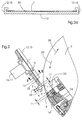
- Fig. 2a shows a section II-II through the plate feed device 13. It is shown how the guide means 12 are designed as U-shaped grips 15. This ensures when inserting the pressure plate 1 that it is guided so that the recesses 5 and 6 engage in the pre-positioning pins 3 and 4 and usually an exact pre-positioning is achieved immediately. When the sensor means 8 and 9 signal such an exact pre-positioning, the holding means 16 designed as a suction cup 17 are activated.
- FIG. 2a further shows how the plate feed device 13 is equipped with sliding devices 25. These can be rollers or beads coated with lubricant.
- FIG. 3 shows a partial area of an exemplary embodiment of a plate feed device 13. Shown are the prepositioning pins 3 and 4 arranged at the lower end, which can be displaced by drives 26, as was shown by the double arrows 22 in FIG. 2. Above the pre-positioning pins 3, 4, holding means 16 designed as lifting suction devices 17 are arranged, their function being described above. Rollers 27 at the end of the plate feed device 13 ensure damage-free guidance of the printing plates 1 in the end region of the plate feed device 13 during transfer to the plate cylinder 2.
- Fig. 4 shows a detail of a plate feed device 13.
- a resilient guide element 19 is arranged in the area of the pre-positioning pins 3 and 4, which ensures that printing plates 1 with which printing has already been carried out and which have a curvature , are guided such that the pre-positioning pins 3 and 4 engage in the recesses 5 and 6 of the pressure plate. As a result, such printing plates 1 can also be handled without problems.
Abstract
Description
- Fig. 1
- eine Skizze einer ersten Ausführungsform einer Sensoranordnung,
- Fig. 1a
- eine weitere Ausführungsform,
- Fig. 2
- ein Ausführungsbeispiel einer Plattenzuführvorrichtung zur Erläuterung der Funktion des erfindungsgemäßen Gegenstandes,
- Fig. 2a
- einen Schnitt II-II durch die Plattenzuführvorrichtung,
- Fig. 3
- einen Teilbereich eines Ausführungsbeispiels einer Plattenzuführvorrichtung und
- Fig. 4
- eine Einzelheit einer Plattenzuführvorrichtung.
- 1
- Druckplatte
- 2
- Plattenzylinder
- 3
- Vorpositionierstift
- 3'
- Positionierstift
- 4
- Vorpositionierstift
- 4'
- Positionierstift
- 3,3',4,4'
- Positioniermittel
- 5
- Ausnehmung
- 6
- Ausnehmung
- 7
- Druckplattenvorderkante
- 8
- Sensormittel
- 9
- Sensormittel
- 10
- Pfeil - Transportrichtung der Druckplatte
- 11
- Versatz der Eingriffspositionen
- 12
- Führungsmittel
- 13
- Plattenzuführvorrichtung
- 14
- Vorderkantenspanneinrichtung
- 15
- U-förmige Umgreifung
- 16
- Haltemittel
- 17
- Hubsauger
- 18
- elektrische Kontakte
- 19
- federnde Führungselemente
- 20
- Auswertvorrichtung
- 21
- Anzeigevorrichtung
- 22
- Doppelpfeile - Wegbewegbarkeit der Positionierstifte der Plattenzuführvorrichtung
- 23
- bewegbare Spannbacke der Vorderkantenspannvorrichtung
- 24
- Doppelpfeil - Spann- bzw. Freigabebewegung der bewegbaren Spannbacke
- 25
- Gleiteinrichtung (Rollen oder Sicken)
- 26
- Antriebe für die Wegbewegung der Positionierstifte
- 27
- Rollen für die Führung der Druckplatte an der Vorderkante der Plattenzuführvorrichtung
- 28
- Pfeil - Rückwärtsdrehung
- 29
- Pfeil - Vorwärtsdrehung
- 30
- Mittellinie
Claims (18)
- Verfahren zur registergenauen Vorpositionierung einer Druckplatte (1) in einer Plattenzuführvorrichtung (13), wobei die Druckplatte (1) durch Positioniermittel (3, 4) der Plattenzuführvorrichtung (13) vorpositioniert und dann dem Plattenzylinder (2) zugeführt und in die Vorderkantenspanneirrichtung (14) desselben eingespannt wird,
dadurch gekennzeichnet,daß die registergenaue Vorpositionierung von Sensormitteln (8, 9) erfaßt und gegebenenfalls korrigiert wird und dann eine registergenaue Übergabe an die Vorderkantenspanneinrichtung (14) des Plattenzylinders (2) erfolgt. - Verfahren nach Anspruch 1,
dadurch gekennzeichnet,daß die Druckplatten (1) in der Position der registergenauen Vorpositionierung gehalten werden und die Aufnahme in die Vorderkantenspanneinrichtung (14) durch ein Rückwärtsdrehen (28) des Plattenzylinders (2) erfolgt. - Verfahren nach Anspruch 1 oder 2,
dadurch gekennzeichnet,daß auch die registergenaue Aufnahme in die Vorderkantenspanneinrichtung (14) des Plattenzylinders (2) durch Sensormittel (8, 9) erfaßt wird, um gegebenenfalls eine Nachkorrektur vorzunehmen. - Vorrichtung zur Durchführung eines Verfahrens nach einem der Ansprüche 1 bis 3 mit einer Plattenzuführvorrichtung (13), welche mindestens zwei Vorpositionierstifte (3, 4) aufweist, die zur Vorpositionierung einer Druckplatte (1) in Ausnehmungen (5, 6) derselben eingreifen und die außer Eingriff bringbar sind, sowie mit Mitteln zur Übergabe der vorpositionierten Druckplatte (1) an die Vorderkantenspanneinrichtung (14) des Plattenzylinders (2),
dadurch gekennzeichnet,daß die Platterzuführvorrichtung (13) Sensormittel (8, 9) zur Erfassung der registergenauen Vorpositionierung der Druckplatte (1) aufweist und die Mittel zur Übergabe der Druckplatte (1) derart ausgebildet sind, daß die registergenaue Vorpositionierung erhalten bleibt. - Vorrichtung nach Anspruch 4,
dadurch gekennzeichnet,daß die Mittel zur Übergabe der Druckplatte (1) ein in der Plattenzuführvorrichtung (13) angeordnetes Haltermittel (16) aufweisen, das die vorpositionierte Druckplatte (1) erfaßt, daß die Vorpositionierstifte (3, 4) mit Antrieben (26) ausgestattet sind, durch die sie außer Eingriffbringbar sind, unddaß die Plattenzuführvorrichtung (13) derart ausgebildet und positionierbar ist,daß die vorpositionierte und gehaltene Druckplatte (1) bei weggefahrenen Vorpositionierstiften (3, 4) durch eine Rückwartsdrehung (28) des Plattenzylinders (2) in die Vorderkantenspanneinrichtung (14) einfügbar ist. - Vorrichtung nach Anspruch 4 oder 5,
dadurch gekennzeichnet,daß das Haltemittel (16) mindestens ein Hubsauger (17) ist. - Vorrichtung nach einem der Ansprüche 4 bis 6,
dadurch gekennzeichnet,daß an der Plattenzuführvorrichtung (13) Führungsmittel (12) angeordnet sind. - Vorrichtung nach Anspruch 7,
dadurch gekennzeichnet,daß die Führungsmittel (12) seitliche U-förmige Umgreifungen (15) sind. - Vorrichtung nach einem der Ansprüche 4 bis 8,
dadurch gekennzeichnet,daß auch die Vorderkantenspanneinrichtung (14) Positionierstifte (3', 4') und Sensormittel (8, 9) zur Erfassung der registergenauen Positionierung aufweist. - Vorrichtung nach einem der Ansprüche 4 bis 9,
dadurch gekennzeichnet,daß ein Vorpositionierstift (3) und/oder Positionierstift (3') und eine Ausnehmung (5) auf einer Seite der Druckplattenvorderkante (7) gegenüber einem weiteren Vorpositionierstift (4) und/oder Positionierstift (4) auf der bezüglich der Mittellinie (30) gegenüberliegenden Seite der Druckplattenvorderkante (7) nicht vertauschbare Eingriffspositionen aufweisen.
- Vorrichtung nach einem der Ansprüche 4 bis 10,
dadurch gekennzeichnet,daß die Sensormittel (8, 9) elektrische Kontakte (18) sind, die bei exaktem Eingriff der Vorpositionierstifte (3, 4) und/oder Positionierstifte (3', 4') in die Ausnehmungen (5, 6) einen Stromkreis schließen. - Vorrichtung nach Anspruch 11,
dadurch gekennzeichnet,daß die Vorpositionierstifte (3, 4) und/oder Positionierstifte (3', 4') nur in einem Teilbereich an ihrer vorderen Seite als elektrische Kontakte (18) ausgebildet sind. - Vorrichtung nach einem der Ansprüche 4 bis 10,
dadurch gekennzeichnet,daß die Sensormittel (8, 9) als kapazitive Sensoren ausgebildet sind. - Vorrichtung nach einem der Ansprüche 4 bis 10,
dadurch gekennzeichnet,daß die Sensormittel (8, 9) optische Sensoren sind. - Vorrichtung nach einem der Ansprüche 4 bis 10,
dadurch gekennzeichnet,daß die Sensormittel (8, 9) Ultraschallsensoren sind. - Vorrichtung nach einem der Ansprüche 4 bis 10,
dadurch gekennzeichnet,daß die Sensormittel (8, 9) induktiv wirkende Sensoren sind. - Vorrichtung nach einem der Ansprüche 4 bis 10,
dadurch gekennzeichnet,daß die Sensormittel (8, 9) Mikroschalter sind. - Vorrichtung nach einem der Ansprüche 4 bis 17,
dadurch gekennzeichnet,daß im Bereich der Vorpositionierstifte (3, 4) federnde Führungselemente (19) angeordnet sind, die die Druckplatte (1) in den Wirkbereich der Vorpositionierstifte (3, 4) drücken.
Applications Claiming Priority (2)
| Application Number | Priority Date | Filing Date | Title |
|---|---|---|---|
| DE19803723 | 1998-01-30 | ||
| DE19803723A DE19803723A1 (de) | 1998-01-30 | 1998-01-30 | Verfahren und Vorrichtung zur registergenauen Vorpositionierung einer Druckplatte |
Publications (2)
| Publication Number | Publication Date |
|---|---|
| EP0933207A1 true EP0933207A1 (de) | 1999-08-04 |
| EP0933207B1 EP0933207B1 (de) | 2002-03-27 |
Family
ID=7856210
Family Applications (1)
| Application Number | Title | Priority Date | Filing Date |
|---|---|---|---|
| EP98123530A Expired - Lifetime EP0933207B1 (de) | 1998-01-30 | 1998-12-16 | Verfahren und Vorrichtung zur registergenauen Vorpositionierung einer Druckplatte |
Country Status (4)
| Country | Link |
|---|---|
| US (1) | US6571708B1 (de) |
| EP (1) | EP0933207B1 (de) |
| JP (1) | JP4584372B2 (de) |
| DE (2) | DE19803723A1 (de) |
Cited By (2)
| Publication number | Priority date | Publication date | Assignee | Title |
|---|---|---|---|---|
| EP1138485A2 (de) * | 2000-03-29 | 2001-10-04 | Koenig & Bauer Aktiengesellschaft | Verfahren und Vorrichtung zum sicheren registergerechten Aufspannen einer Druckplatte auf den Plattenzylinder einer Bogendruckmaschine |
| US8601946B2 (en) | 2008-12-02 | 2013-12-10 | Heidelberger Druckmaschinen Ag | Method and apparatus for automatically feeding printing plates and printing press having the apparatus |
Families Citing this family (13)
| Publication number | Priority date | Publication date | Assignee | Title |
|---|---|---|---|---|
| CZ297967B6 (cs) * | 2000-08-25 | 2007-05-09 | Heidelberger Druckmaschienen Ag | Zarízení na prestavování minimálne jednoho prvku registru v tiskovém stroji a zpusob k provádení takového prestavování |
| US6739250B2 (en) * | 2002-03-20 | 2004-05-25 | Fuji Photo Film Co., Ltd. | Device for controlling rotation of rotating drum |
| DE10338372A1 (de) * | 2003-08-21 | 2005-03-17 | Koenig & Bauer Ag | Verfahren zum Zuführen von Druckplatten zum Plattenzylinder einer Druckmaschine |
| GB2413530A (en) * | 2004-04-29 | 2005-11-02 | Goss Graphic Systems Ltd | Printing plate module and printing press |
| US8051774B2 (en) * | 2004-04-29 | 2011-11-08 | Goss Graphic Systems Limited | Printing plate module, printing press, and method of mounting plates |
| DE102004042268A1 (de) * | 2004-09-01 | 2006-03-02 | Koenig & Bauer Ag | Verfahren zum Zuführen einer in einem Plattenmagazin bereitgestellten Druckplatte |
| DE102004052824A1 (de) * | 2004-11-02 | 2006-05-04 | Koenig & Bauer Ag | Verfahren und Vorrichtung zum Zuführen einer Druckplatte |
| GB2425987A (en) * | 2005-05-09 | 2006-11-15 | Goss Graphic Systems Ltd | Printing plate unloading apparatus and method |
| GB2428634B (en) * | 2005-08-04 | 2008-09-17 | Goss Graphic Systems Ltd | Printing press |
| US7819060B2 (en) * | 2007-04-13 | 2010-10-26 | E.I. Du Pont De Nemours And Company | Method for mounting cylindrically-shaped printing forms |
| DE102007039824B4 (de) * | 2007-08-23 | 2009-05-20 | Manroland Ag | Registerstegeinrichtung für eine Bogendruckmaschine |
| DE102009012147A1 (de) | 2008-03-27 | 2009-10-01 | Heidelberger Druckmaschinen Ag | Verfahren und Vorrichtung zum Zuführen von Druckplatten zu einem Plattenzylinder einer Verarbeitungsmaschine |
| US10703090B2 (en) * | 2015-03-20 | 2020-07-07 | Bobst Firenze S.R.L. | Apparatus and method for mounting a printing plate on a printing carrier |
Citations (6)
| Publication number | Priority date | Publication date | Assignee | Title |
|---|---|---|---|---|
| EP0581212A1 (de) * | 1992-07-31 | 1994-02-02 | Komori Corporation | Vorrichtung zum Montieren einer Druckplatte für eine Druckpresse |
| EP0582903A1 (de) * | 1992-08-13 | 1994-02-16 | MAN Roland Druckmaschinen AG | Vorrichtung zur Kontrolle der registergerechten Anlage einer Druckplatte auf dem Plattenzylinder von Druckmaschinen, insbesondere Bogenoffsetdruckmaschinen |
| DE19508844A1 (de) * | 1995-03-11 | 1996-09-12 | Kba Planeta Ag | Vorrichtung zum Zu- und Abführen von Druckplatten |
| DE29615902U1 (de) * | 1996-09-12 | 1997-01-02 | Lehner Gmbh | Einrichtung zum Spannen einer Druckplatte auf einem Formzylinder |
| DE19539453A1 (de) * | 1995-10-24 | 1997-04-30 | Heinz Metje | Paßsystem zum Ausrichten von Druckplatten für Offset-Druckmaschinen |
| EP0808714A2 (de) * | 1996-05-24 | 1997-11-26 | KOENIG & BAUER-ALBERT AKTIENGESELLSCHAFT | Verfahren und Vorrichtung zum axialen Positionieren einer Druckplatte |
Family Cites Families (26)
| Publication number | Priority date | Publication date | Assignee | Title |
|---|---|---|---|---|
| US3882775A (en) * | 1973-07-02 | 1975-05-13 | World Color Press | Registration system for thin magnetic printing plates |
| DE3138865C2 (de) * | 1981-09-30 | 1983-12-29 | Grapho Metronic Meß- und Regeltechnik GmbH & Co KG, 8000 München | Vorrichtung zur Kontrolle des registergenauen Aufspannens von Druckplatten auf dem Plattenzylinder einer Offset-Druckmaschine |
| IT1183507B (it) * | 1985-03-28 | 1987-10-22 | Arnoldo Mandadori Editore Offi | Dispositivo di messa a registro delle lastre da stampa sui cilindri di macchine da stampa offset piane |
| JPS62221541A (ja) * | 1986-03-25 | 1987-09-29 | Mitsubishi Heavy Ind Ltd | 自動刷版装着装置 |
| DE3710257A1 (de) | 1987-03-28 | 1988-10-13 | Heidelberger Druckmasch Ag | Bogen-rotationsdruckmaschine zur herstellung von einseitigem mehrfarbendruck oder schoen- und widerdruck |
| ATE130801T1 (de) * | 1989-08-04 | 1995-12-15 | Komori Printing Mach | Druckplattebefestigung für eine bogendruckmaschine. |
| DE3940796A1 (de) * | 1989-12-09 | 1991-06-13 | Koenig & Bauer Ag | Verfahren und einrichtung zum automatischen wechseln einer druckplatte |
| US5289773A (en) * | 1991-03-14 | 1994-03-01 | Komori Corporation | Apparatus for mounting plate on plate cylinder |
| JP2590784Y2 (ja) * | 1991-06-06 | 1999-02-17 | 株式会社 小森コーポレーション | 印刷機の刷版供給装置 |
| DE4126643A1 (de) | 1991-08-12 | 1993-02-18 | Koenig & Bauer Ag | Trommel zum transportieren und uebergeben von bogen |
| DE4130359C2 (de) | 1991-09-12 | 1997-04-17 | Heidelberger Druckmasch Ag | Vorrichtung zum Ab- und/oder Zuführen von Druckplatten einer Druckmaschine |
| JP3194199B2 (ja) * | 1992-01-17 | 2001-07-30 | 株式会社小森コーポレーション | 版胴への刷版装着装置 |
| JP3379974B2 (ja) * | 1992-02-10 | 2003-02-24 | 株式会社小森コーポレーション | 刷版装着状況確認装置 |
| DE4217941C2 (de) * | 1992-05-30 | 1994-10-06 | Koenig & Bauer Ag | Verfahren und Vorrichtung zum paßgenauen Aufbringen von Klischees |
| JP2586447Y2 (ja) * | 1992-10-26 | 1998-12-09 | 株式会社小森コーポレーション | 印刷機の刷版保持装置 |
| DE9215069U1 (de) * | 1992-11-05 | 1992-12-17 | Man Roland Druckmaschinen Ag, 6050 Offenbach, De | |
| JP2566263Y2 (ja) * | 1992-12-03 | 1998-03-25 | 大日本スクリーン製造株式会社 | 刷版画像記録装置 |
| DE4306677C2 (de) * | 1993-03-04 | 1995-01-19 | Heidelberger Druckmasch Ag | Vorrichtung zur Druckvorbereitung mit einer Druckform einer Druckmaschine |
| DE4327013C1 (de) | 1993-08-12 | 1995-01-12 | Heidelberger Druckmasch Ag | Druckplatten-Kassette für ein Magazin |
| DE4332803C2 (de) * | 1993-09-27 | 1996-10-24 | Roland Man Druckmasch | Vorrichtung zum automatischen Zuführen von Druckplatten zum Plattenzylinder einer Druckmaschine |
| DE4338664C2 (de) * | 1993-11-12 | 1995-09-14 | Roland Man Druckmasch | Verfahren und Vorrichtung zum Steuern eines automatisierten Druckplattenwechselvorganges bei Druckmaschinen |
| DE4439623C2 (de) * | 1994-11-05 | 1999-01-14 | Roland Man Druckmasch | Verfahren zum automatischen Zuführen von Druckplatten |
| JP2691974B2 (ja) * | 1994-11-16 | 1997-12-17 | 株式会社東京機械製作所 | 刷版支持装置及び刷版着脱装置 |
| JPH09156077A (ja) * | 1995-12-05 | 1997-06-17 | Toyo Ink Mfg Co Ltd | 画像転写装置および画像転写方法 |
| DE19611530C1 (de) * | 1996-03-23 | 1997-10-16 | Roland Man Druckmasch | Verfahren und Vorrichtung zur Steuerung eines automatisierten Druckplattenwechselvorganges bei einer Druckmaschine |
| DE19636703C2 (de) * | 1996-09-10 | 1998-12-03 | Roland Man Druckmasch | Vorrichtung zur automatischen Steuerung eines Druckplattenwechselvorganges |
-
1998
- 1998-01-30 DE DE19803723A patent/DE19803723A1/de not_active Withdrawn
- 1998-12-16 DE DE59803502T patent/DE59803502D1/de not_active Expired - Lifetime
- 1998-12-16 EP EP98123530A patent/EP0933207B1/de not_active Expired - Lifetime
-
1999
- 1999-02-01 JP JP02415599A patent/JP4584372B2/ja not_active Expired - Fee Related
- 1999-02-01 US US09/243,835 patent/US6571708B1/en not_active Expired - Fee Related
Patent Citations (6)
| Publication number | Priority date | Publication date | Assignee | Title |
|---|---|---|---|---|
| EP0581212A1 (de) * | 1992-07-31 | 1994-02-02 | Komori Corporation | Vorrichtung zum Montieren einer Druckplatte für eine Druckpresse |
| EP0582903A1 (de) * | 1992-08-13 | 1994-02-16 | MAN Roland Druckmaschinen AG | Vorrichtung zur Kontrolle der registergerechten Anlage einer Druckplatte auf dem Plattenzylinder von Druckmaschinen, insbesondere Bogenoffsetdruckmaschinen |
| DE19508844A1 (de) * | 1995-03-11 | 1996-09-12 | Kba Planeta Ag | Vorrichtung zum Zu- und Abführen von Druckplatten |
| DE19539453A1 (de) * | 1995-10-24 | 1997-04-30 | Heinz Metje | Paßsystem zum Ausrichten von Druckplatten für Offset-Druckmaschinen |
| EP0808714A2 (de) * | 1996-05-24 | 1997-11-26 | KOENIG & BAUER-ALBERT AKTIENGESELLSCHAFT | Verfahren und Vorrichtung zum axialen Positionieren einer Druckplatte |
| DE29615902U1 (de) * | 1996-09-12 | 1997-01-02 | Lehner Gmbh | Einrichtung zum Spannen einer Druckplatte auf einem Formzylinder |
Cited By (3)
| Publication number | Priority date | Publication date | Assignee | Title |
|---|---|---|---|---|
| EP1138485A2 (de) * | 2000-03-29 | 2001-10-04 | Koenig & Bauer Aktiengesellschaft | Verfahren und Vorrichtung zum sicheren registergerechten Aufspannen einer Druckplatte auf den Plattenzylinder einer Bogendruckmaschine |
| EP1138485A3 (de) * | 2000-03-29 | 2003-08-20 | Koenig & Bauer Aktiengesellschaft | Verfahren und Vorrichtung zum sicheren registergerechten Aufspannen einer Druckplatte auf den Plattenzylinder einer Bogendruckmaschine |
| US8601946B2 (en) | 2008-12-02 | 2013-12-10 | Heidelberger Druckmaschinen Ag | Method and apparatus for automatically feeding printing plates and printing press having the apparatus |
Also Published As
| Publication number | Publication date |
|---|---|
| JPH11262998A (ja) | 1999-09-28 |
| JP4584372B2 (ja) | 2010-11-17 |
| DE19803723A1 (de) | 1999-08-05 |
| DE59803502D1 (de) | 2002-05-02 |
| EP0933207B1 (de) | 2002-03-27 |
| US6571708B1 (en) | 2003-06-03 |
Similar Documents
| Publication | Publication Date | Title |
|---|---|---|
| EP0933207B1 (de) | Verfahren und Vorrichtung zur registergenauen Vorpositionierung einer Druckplatte | |
| DE4226780C2 (de) | Vorrichtung zur Kontrolle der registergerechten Anlage einer Druckplatte auf dem Plattenzylinder von Druckmaschinen, insbesondere Bogenoffsetdruckmaschinen | |
| EP0201747B1 (de) | Vorrichtung zum parallelen Spannen von Druckplatten auf dem Plattenzylinder von Druckmaschinen | |
| DE19854845A1 (de) | Verfahren und Vorrichtung zur automatischen Erfassung von mindestens einer Druckplattenkante | |
| EP0933204A1 (de) | Vorrichtung zur registergenauen Positionierung einer Druckplatte | |
| DE60010672T2 (de) | Vorrichtung und Verfahren zum Bedrucken von Drähten | |
| DE19801844A1 (de) | Vorrichtung zum Einfügen der Kante einer Platte für eine Druckmaschine | |
| DE2722439C2 (de) | Vorrichtung zum seitlichen Ausrichten von Bogen an Druckmaschinen o.dgl. | |
| DE2751971C2 (de) | ||
| DE10145100A1 (de) | Lichtsensor für Bogenprodukte | |
| EP0607196B1 (de) | Verfahren zum betrieb einer vorrichtung zum herstellen von etiketten aus bändchenmaterial | |
| DE4241795C2 (de) | Vorrichtung zum paßgenauen Anlegen | |
| DE3150169A1 (de) | Vorrichtung zum seitlichen ausrichten von bogen in einer druckmaschine | |
| DE4332803C2 (de) | Vorrichtung zum automatischen Zuführen von Druckplatten zum Plattenzylinder einer Druckmaschine | |
| DE4311078C1 (de) | Vorrichtung zur Erzeugung einer Hülse, insbesondere einer hülsenförmigen Druckform, mit zusammenhängender Umfangsfläche | |
| DE1786196A1 (de) | Verfahren und Vorrichtung zur Papierblatteinstellung bei Druckmaschinen | |
| DE2320333C2 (de) | Vorrichtung zum schrittweisen Abzug eines Etikettenbandes | |
| DE2624170B2 (de) | Seitenausrichtvorrichtung | |
| DE10008489B4 (de) | Verfahren und Vorrichtung zur Zuführung einer Druckplatte | |
| AT402206B (de) | Übergabevorrichtung zum einschieben von etiketten in den nähbereich einer nähmaschine | |
| DE10001322B4 (de) | Verfahren zum automatischen Zuführen von Druckplatten an Druckmaschinen | |
| EP1116584B1 (de) | Verfahren zum lagegenauen Zuführen von Druckplatten aus einem Plattenmagazin | |
| DE4417514C1 (de) | Verfahren zur taktweisen Verpressung von Keilzinkenverbindungen und Taktpresse dafür | |
| DE1940949C3 (de) | Falzmaschine | |
| EP0283834A2 (de) | Vorrichtung zum Anbringen einer den Anfang eines bandförmigen Materials führenden Klammer an ein Schleppband |
Legal Events
| Date | Code | Title | Description |
|---|---|---|---|
| PUAI | Public reference made under article 153(3) epc to a published international application that has entered the european phase |
Free format text: ORIGINAL CODE: 0009012 |
|
| AK | Designated contracting states |
Kind code of ref document: A1 Designated state(s): BE CH DE FR GB IT LI NL |
|
| AX | Request for extension of the european patent |
Free format text: AL;LT;LV;MK;RO;SI |
|
| 17P | Request for examination filed |
Effective date: 19990820 |
|
| AKX | Designation fees paid |
Free format text: BE CH DE FR GB IT LI NL |
|
| 17Q | First examination report despatched |
Effective date: 20000718 |
|
| GRAG | Despatch of communication of intention to grant |
Free format text: ORIGINAL CODE: EPIDOS AGRA |
|
| GRAG | Despatch of communication of intention to grant |
Free format text: ORIGINAL CODE: EPIDOS AGRA |
|
| GRAH | Despatch of communication of intention to grant a patent |
Free format text: ORIGINAL CODE: EPIDOS IGRA |
|
| GRAH | Despatch of communication of intention to grant a patent |
Free format text: ORIGINAL CODE: EPIDOS IGRA |
|
| REG | Reference to a national code |
Ref country code: GB Ref legal event code: IF02 |
|
| GRAA | (expected) grant |
Free format text: ORIGINAL CODE: 0009210 |
|
| AK | Designated contracting states |
Kind code of ref document: B1 Designated state(s): BE CH DE FR GB IT LI NL |
|
| REG | Reference to a national code |
Ref country code: CH Ref legal event code: EP |
|
| REF | Corresponds to: |
Ref document number: 59803502 Country of ref document: DE Date of ref document: 20020502 |
|
| ET | Fr: translation filed | ||
| PGFP | Annual fee paid to national office [announced via postgrant information from national office to epo] |
Ref country code: GB Payment date: 20021125 Year of fee payment: 5 |
|
| PGFP | Annual fee paid to national office [announced via postgrant information from national office to epo] |
Ref country code: FR Payment date: 20021217 Year of fee payment: 5 |
|
| PGFP | Annual fee paid to national office [announced via postgrant information from national office to epo] |
Ref country code: BE Payment date: 20021219 Year of fee payment: 5 Ref country code: NL Payment date: 20021219 Year of fee payment: 5 |
|
| PGFP | Annual fee paid to national office [announced via postgrant information from national office to epo] |
Ref country code: CH Payment date: 20021230 Year of fee payment: 5 |
|
| PLBE | No opposition filed within time limit |
Free format text: ORIGINAL CODE: 0009261 |
|
| STAA | Information on the status of an ep patent application or granted ep patent |
Free format text: STATUS: NO OPPOSITION FILED WITHIN TIME LIMIT |
|
| 26N | No opposition filed |
Effective date: 20021230 |
|
| PG25 | Lapsed in a contracting state [announced via postgrant information from national office to epo] |
Ref country code: GB Free format text: LAPSE BECAUSE OF NON-PAYMENT OF DUE FEES Effective date: 20031216 |
|
| PG25 | Lapsed in a contracting state [announced via postgrant information from national office to epo] |
Ref country code: LI Free format text: LAPSE BECAUSE OF NON-PAYMENT OF DUE FEES Effective date: 20031231 Ref country code: CH Free format text: LAPSE BECAUSE OF NON-PAYMENT OF DUE FEES Effective date: 20031231 Ref country code: BE Free format text: LAPSE BECAUSE OF NON-PAYMENT OF DUE FEES Effective date: 20031231 |
|
| BERE | Be: lapsed |
Owner name: *HEIDELBERGER DRUCKMASCHINEN A.G. Effective date: 20031231 |
|
| PG25 | Lapsed in a contracting state [announced via postgrant information from national office to epo] |
Ref country code: NL Free format text: LAPSE BECAUSE OF NON-PAYMENT OF DUE FEES Effective date: 20040701 |
|
| GBPC | Gb: european patent ceased through non-payment of renewal fee |
Effective date: 20031216 |
|
| REG | Reference to a national code |
Ref country code: CH Ref legal event code: PL |
|
| PG25 | Lapsed in a contracting state [announced via postgrant information from national office to epo] |
Ref country code: FR Free format text: LAPSE BECAUSE OF NON-PAYMENT OF DUE FEES Effective date: 20040831 |
|
| NLV4 | Nl: lapsed or anulled due to non-payment of the annual fee |
Effective date: 20040701 |
|
| REG | Reference to a national code |
Ref country code: FR Ref legal event code: ST |
|
| PG25 | Lapsed in a contracting state [announced via postgrant information from national office to epo] |
Ref country code: IT Free format text: LAPSE BECAUSE OF NON-PAYMENT OF DUE FEES Effective date: 20051216 |
|
| PGFP | Annual fee paid to national office [announced via postgrant information from national office to epo] |
Ref country code: DE Payment date: 20130128 Year of fee payment: 15 |
|
| REG | Reference to a national code |
Ref country code: DE Ref legal event code: R119 Ref document number: 59803502 Country of ref document: DE |
|
| REG | Reference to a national code |
Ref country code: DE Ref legal event code: R119 Ref document number: 59803502 Country of ref document: DE Effective date: 20140701 |
|
| PG25 | Lapsed in a contracting state [announced via postgrant information from national office to epo] |
Ref country code: DE Free format text: LAPSE BECAUSE OF NON-PAYMENT OF DUE FEES Effective date: 20140701 |