EP0933207A1 - Method and apparatus for prepositioning of a printing plate true to register - Google Patents
Method and apparatus for prepositioning of a printing plate true to register Download PDFInfo
- Publication number
- EP0933207A1 EP0933207A1 EP98123530A EP98123530A EP0933207A1 EP 0933207 A1 EP0933207 A1 EP 0933207A1 EP 98123530 A EP98123530 A EP 98123530A EP 98123530 A EP98123530 A EP 98123530A EP 0933207 A1 EP0933207 A1 EP 0933207A1
- Authority
- EP
- European Patent Office
- Prior art keywords
- plate
- positioning
- register
- prepositioning
- sensor means
- Prior art date
- Legal status (The legal status is an assumption and is not a legal conclusion. Google has not performed a legal analysis and makes no representation as to the accuracy of the status listed.)
- Granted
Links
Images


Classifications
-
- B—PERFORMING OPERATIONS; TRANSPORTING
- B41—PRINTING; LINING MACHINES; TYPEWRITERS; STAMPS
- B41F—PRINTING MACHINES OR PRESSES
- B41F27/00—Devices for attaching printing elements or formes to supports
- B41F27/12—Devices for attaching printing elements or formes to supports for attaching flexible printing formes
-
- B—PERFORMING OPERATIONS; TRANSPORTING
- B41—PRINTING; LINING MACHINES; TYPEWRITERS; STAMPS
- B41P—INDEXING SCHEME RELATING TO PRINTING, LINING MACHINES, TYPEWRITERS, AND TO STAMPS
- B41P2227/00—Mounting or handling printing plates; Forming printing surfaces in situ
- B41P2227/30—Detecting the correct position of printing plates on the cylinder
-
- Y—GENERAL TAGGING OF NEW TECHNOLOGICAL DEVELOPMENTS; GENERAL TAGGING OF CROSS-SECTIONAL TECHNOLOGIES SPANNING OVER SEVERAL SECTIONS OF THE IPC; TECHNICAL SUBJECTS COVERED BY FORMER USPC CROSS-REFERENCE ART COLLECTIONS [XRACs] AND DIGESTS
- Y10—TECHNICAL SUBJECTS COVERED BY FORMER USPC
- Y10S—TECHNICAL SUBJECTS COVERED BY FORMER USPC CROSS-REFERENCE ART COLLECTIONS [XRACs] AND DIGESTS
- Y10S101/00—Printing
- Y10S101/36—Means for registering or alignment of print plates on print press structure
Definitions
- the invention relates to a method for pre-positioning a register Printing plate in a plate feed device, wherein the printing plate through Positioning means of the plate feeder prepositioned and then the Plate cylinder fed and the same in the leading edge clamping device is clamped.
- the invention further relates to a device for carrying out the method a plate feed device which has at least two positioning pins which to pre-position a printing plate in recesses of the same and the can be disengaged, as well as means for transferring the prepositioned Pressure plate to the front edge clamping device of the plate cylinder.
- Such prepositioning of a printing plate is known from DE 195 08 844 A1 known.
- the plate feed device known from this document is not can be checked whether the pre-positioning has been carried out correctly and thus in register.
- a transport device provided on which suction cups are arranged, which are the prepositioned pressure plate to capture. Then the transport device, by pneumatic cylinder driven, the pressure plate in the front edge clamping device of the plate cylinder.
- This type of transfer of the pre-positioned printing plate to the Leading edge tensioning device is not only complex and expensive, but also too inaccurate to register the pre-positioned printing plate to the Hand over the leading edge clamping device of the plate cylinder.
- the invention is therefore based on the object that the method mentioned and the device mentioned at the outset are designed such that the control of the accurate positioning of the printing plate and the correction of the same as far as possible while the machine is running.
- the object is achieved in that the Precise register positioning of sensor means recorded and if necessary is corrected and then an accurate transfer to the Leading edge clamping device of the plate cylinder takes place.
- the object is achieved in that the Plate feed device sensor means for register-accurate registration Has prepositioning of the printing plate and the means for transferring the Pressure plate are designed in such a way that the register-accurate prepositioning is obtained remains.
- the printing plate is provided in register so that after the transfer of the pre-positioned printing plate to the plate cylinder usually only the fine adjustments still have to be made while the machine is at a standstill a test print is required anyway. Correcting the positioning of the Pressure plate after insertion into the leading edge tensioning device is in front of the It is usually no longer necessary to carry out a test print because of the Invention these corrections are moved to the printing plate feeder. On in this way, such corrections can already be made at a time when the Press still prints the previous job. In this way the Machine downtimes are shortened, increasing the machine's profitability.
- a particularly advantageous with regard to the register accuracy of the transfer Development of the method provides that the printing plates in the position of Precise pre-positioning can be held and the inclusion in the Front edge tensioning device is carried out by turning the plate cylinder backwards.
- An expedient embodiment provides that the register-accurate recording in the leading edge clamping device of the plate cylinder is detected by sensor means, to check the correctness of the delivery and, if necessary, a correction to be able to make. This way another check is done and it is possible that misadjustments and malfunctions even before a Sample prints can be noticed and corrected.
- the Means for transferring the printing plate arranged in the plate feed device Have holding means that detects the prepositioned printing plate that the Pre-positioning pins are equipped with drives that disengage them can be brought, and that the plate feeder is designed and is positionable that the pre-positioned and held pressure plate when removed Pre-positioning pins by turning the plate cylinder backwards into the Front edge tensioning device can be inserted.
- the Holding means is at least one suction cup.
- a further development provides that the leading edge tensioning device Positioning pins and sensor means for registering the exact positioning having. As already mentioned for the procedure, errors that occur can be detected immediately and be corrected in time.
- An embodiment for preventing the reverse use of a Pressure plate suggests that a pre-positioning pin and / or positioning pin and one Recess on one side of a printing plate leading edge compared to another Pre-positioning pin and / or positioning pin on the center line opposite side of the printing plate leading edge not interchangeable Have engagement positions. Leave these non-interchangeable engagement positions evolve in different ways, regarding the Design options are referred to the description of the figures.
- the sensor means electrical Contacts are the exact engagement of the prepositioning pins and / or Positioning pins in the recesses close a circuit, for example via the pressure plate.
- the Pre-positioning pins and / or positioning pins only in a partial area on their front Side are designed as electrical contacts. This ensures that it is too the electrical contact only comes when the positioning pins are completely in the Apply recesses.
- capacitive or inductive sensors can also be used as sensor means be used.
- plastic printing plates can be used optical sensors, ultrasonic sensors or microswitches can also be provided.
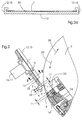
- FIG. 1 shows a possible arrangement of sensor means 8 and 9 for detecting the register-accurate pre-positioning of a printing plate 1 in a plate feed device 13 or also for registering the register-accurate positioning in the front edge clamping device 14 of a plate cylinder 2.
- prepositioning pins 3 and 4 or on positioning pins 3 'and 4' are electrical Contacts 18 arranged which when the pre-positioning pins 3, 4 or Positioning pins 3 ', 4' in recesses 5, 6 of a pressure plate 1 touch and thereby closing a circuit.
- the signal can be sent to an evaluation device 20 are given and a display device 21 indicates that the printing plate 1 is positioned exactly in register.
- the signal can of course also be sent to the Machine controls are given which, upon receipt, pave the way for further Approves procedural steps.
- FIG. 1 a shows a further embodiment, the prepositioning pins 3, 4 or positioning pins 3 ', 4' not yet having engaged in the recesses 5, 6 of the pressure plate 1.
- Both in FIG. 1 and in FIG. 1a are shapes of the prepositioning pins 3, 4 or the positioning pins 3 ', 4' and the recesses 5, 6 of the pressure plate 1 selected by which contact is only given when the pressure plate 1 is inserted correctly is possible.
- These different forms are expediently one
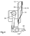
- FIG. 2 shows an exemplary embodiment of a plate feed device 13 and its interaction with the front edge clamping device 14 of a plate cylinder 2.
- pre-positioning pins 3, 4 are arranged which can be moved in the direction of the double arrows 22. As a result, they can be brought into an engagement position in which, as shown in FIG. 1, they engage in recesses 5 and 6 of a pressure plate 1.
- These prepositioning pins 3, 4 have sensor means 8 and 9, which are either designed as shown in FIGS. 1 and 1a or have another of the design options mentioned above.
- a printing plate 1 is inserted into the plate feed device 13 from above, then it is guided by guide means 12 and as long in the direction of arrow 10 inserted until the recesses 5 and 6 into the prepositioning pins 3 and 4 intervention.
- the sensor means 8 and 9 report the exact contact of the recesses 5 and 6 on the prepositioning pins 3 and 4, holding means 16 can take action.
- these are designed as suction cups 17, which are preferably spaced apart in the vertical direction.
- the Pressure plate 1 keeps exactly their pre-positioning, held by the suction cups 17 at.
- the pre-positioning pins 3 and 4 By arranging the pre-positioning pins 3 and 4 on the lower End of the plate feeder 13 and by the training and positioning the plate feeder 13, it is possible that the printing plate leading edge 7 of the front edge clamping device 14 of the plate cylinder 2 is received.
- the plate cylinder 2 rotates from the drawn position in the direction of the arrow 28 backwards until the pressure plate 1 is inserted into the front edge tensioning device 14.
- the positioning pins 3 'and 4' can repeated control of the positioning also equipped with sensor means 8, 9 be.
- the plate cylinder 2 After the insertion of the printing plate leading edge 7 in the Leading edge clamping device 14 closes the movable clamping jaw 23 and inhibits thereby the printing plate leading edge 7.
- the double arrow 24 indicates the tension or Release movement of the movable jaw 23 on.
- the plate cylinder 2 After clamping the Printing plate 1, the plate cylinder 2 makes a forward rotation in the direction of Arrow 29 and takes on the pressure plate 1, which at the end with its rear edge can still be inserted into a rear edge tensioning device and tensioned.
- the prepositioning pins 3 and 4 and Positioning pins 3 'and 4' have an offset 11 of their engagement positions, thereby creating a reverse insertion is no longer possible.
- the front edge tensioning device 14 must be equipped with guide means 12 which an inclined position of the pressure plate 1 with a contact despite reverse Prevent insertion.
- Fig. 2a shows a section II-II through the plate feed device 13. It is shown how the guide means 12 are designed as U-shaped grips 15. This ensures when inserting the pressure plate 1 that it is guided so that the recesses 5 and 6 engage in the pre-positioning pins 3 and 4 and usually an exact pre-positioning is achieved immediately. When the sensor means 8 and 9 signal such an exact pre-positioning, the holding means 16 designed as a suction cup 17 are activated.
- FIG. 2a further shows how the plate feed device 13 is equipped with sliding devices 25. These can be rollers or beads coated with lubricant.
- FIG. 3 shows a partial area of an exemplary embodiment of a plate feed device 13. Shown are the prepositioning pins 3 and 4 arranged at the lower end, which can be displaced by drives 26, as was shown by the double arrows 22 in FIG. 2. Above the pre-positioning pins 3, 4, holding means 16 designed as lifting suction devices 17 are arranged, their function being described above. Rollers 27 at the end of the plate feed device 13 ensure damage-free guidance of the printing plates 1 in the end region of the plate feed device 13 during transfer to the plate cylinder 2.
- Fig. 4 shows a detail of a plate feed device 13.
- a resilient guide element 19 is arranged in the area of the pre-positioning pins 3 and 4, which ensures that printing plates 1 with which printing has already been carried out and which have a curvature , are guided such that the pre-positioning pins 3 and 4 engage in the recesses 5 and 6 of the pressure plate. As a result, such printing plates 1 can also be handled without problems.
Abstract
Description
Die Erfindung betrifft ein Verfahren zur registergenauen Vorpositionierung einer Druckplatte in einer Plattenzuführvorrichtung, wobei die Druckplatte durch Positioniermittel der Plattenzuführvorrichtung vorpositioniert und dann dem Plattenzylinder zugeführt und in die Vorderkantenspanneirrichtung desselben eingespannt wird.The invention relates to a method for pre-positioning a register Printing plate in a plate feed device, wherein the printing plate through Positioning means of the plate feeder prepositioned and then the Plate cylinder fed and the same in the leading edge clamping device is clamped.
Die Erfindung betrifft weiterhin eine Vorrichtung zur Durchführung des Verfahrens mit einer Plattenzuführvorrichtung, welche mindestens zwei Positionierstifte aufweist, die zur Vorpositionierung einer Druckplatte in Ausnehmungen derselben eingreifen und die außer Eingriff bringbar sind, sowie mit Mitteln zur Übergabe der vorpositionierten Druckplatte an die Vorderkantenspanneinrichtung des Plattenzylinders.The invention further relates to a device for carrying out the method a plate feed device which has at least two positioning pins which to pre-position a printing plate in recesses of the same and the can be disengaged, as well as means for transferring the prepositioned Pressure plate to the front edge clamping device of the plate cylinder.
Eine derartige Vorpositionierung einer Druckplatte ist aus der DE 195 08 844 A1 bekannt. Bei der aus dieser Schrift bekannten Plattenzuführvorrichtung ist nicht überprüfbar, ob die Vorpositionierung korrekt und damit registergenau erfolgt ist. Außerdem ist als Mittel zur Übergabe der vorpositionierten Druckplatte an die Vorderkantenspanneinrichtung des Plattenzylinders eine Transporteinrichtung vorgesehen, auf der Sauger angeordnet sind, welche die vorpositionierte Druckplatte erfassen. Danach befordert die Transporteinrichtung, durch Pneumatikzylinder angetrieben, die Druckplatte in die Vorderkantenspanneinrichtung des Plattenzylinders. Diese Art der Übergabe der vorpositionierten Druckplatte an die Vorderkantenspanneinrichtung ist nicht nur aufwendig und teuer, sondern auch zu ungenau, um die vorpositionierte Druckplatte registergenau an die Vorderkantenspanneinrichtung des Plattenzylinders zu übergeben.Such prepositioning of a printing plate is known from DE 195 08 844 A1 known. In the plate feed device known from this document is not can be checked whether the pre-positioning has been carried out correctly and thus in register. In addition, as a means of transferring the pre-positioned printing plate to the Leading edge clamping device of the plate cylinder a transport device provided on which suction cups are arranged, which are the prepositioned pressure plate to capture. Then the transport device, by pneumatic cylinder driven, the pressure plate in the front edge clamping device of the plate cylinder. This type of transfer of the pre-positioned printing plate to the Leading edge tensioning device is not only complex and expensive, but also too inaccurate to register the pre-positioned printing plate to the Hand over the leading edge clamping device of the plate cylinder.
Sowohl aus der Nichtüberprüfung der Registergenauigkeit der Vorpositionierung als auch aus der Ausgestaltung der Mittel zur Übergabe der vorpositionierten Druckplatte an die Vorderkantenspanneinrichtung des Plattenzylinders ergibt sich, daß die Kontrolle der registergenauen Positionierung erst nach Einfügung in die Vorderkantenspanneinrichtung erfolgt. Dies hat jedoch den Nachteil, daß die Kontrolle und Korrektur der Registergenauigkeit der Positionierung der Druckplatte voll während des Maschinenstillstands erfolgen muß. Dadurch wird die erforderliche Rüstzeit verlängert, was zu einer geringeren Maschinenausnutzung führt.Both from the non-checking of the register accuracy of the pre-positioning as also from the design of the means for transferring the prepositioned printing plate to the leading edge tensioning device of the plate cylinder shows that the control the exact positioning only after insertion in the Leading edge tensioning device takes place. However, this has the disadvantage that the control and correcting the registration accuracy of the positioning of the printing plate fully during machine downtime. This will set up the required time lengthened, which leads to lower machine utilization.
Der Erfindung liegt daher die Aufgabe zugrunde, daß das eingangs genannten Verfahren und die eingangs genannte Vorrichtung derart ausgestaltet werden, daß die Kontrolle der registergenauen Positionierung der Druckplatte sowie die Korrektur desselben so weitgehendst wie möglich während des Maschinenlaufs erfolgen können.The invention is therefore based on the object that the method mentioned and the device mentioned at the outset are designed such that the control of the accurate positioning of the printing plate and the correction of the same as far as possible while the machine is running.
Bezuglich des Verfahrens wird die Aufgabe dadurch gelöst, daß die registergenaue Vorpositionierung von Sensormitteln erfaßt und gegebenenfalls korrigiert wird und dann eine registergenaue Übergabe an die Vorderkantenspanneinrichtung des Plattenzylinders erfolgt.With regard to the method, the object is achieved in that the Precise register positioning of sensor means recorded and if necessary is corrected and then an accurate transfer to the Leading edge clamping device of the plate cylinder takes place.
Bezüglich der Vorrichtung wird die Aufgabe erfindungsgemäß dadurch gelöst, daß die Plattenzuführvorrichtung Sensormittel zur Erfassung der registergenauen Vorpositionierung der Druckplatte aufweist und die Mittel zur Übergabe der Druckplatte derart ausgebildet sind, daß die registergenaue Vorpositionierung erhalten bleibt.With regard to the device, the object is achieved in that the Plate feed device sensor means for register-accurate registration Has prepositioning of the printing plate and the means for transferring the Pressure plate are designed in such a way that the register-accurate prepositioning is obtained remains.
Durch die Erfindung wird die Druckplatte derart registergenau bereitgestellt, daß nach der Übergabe der vorpositionierten Druckplatte an den Plattenzylinder in der Regel nur noch die Feinkorrekturen während des Maschinenstillstands erfolgen müssen, die ohnehin einen Probedruck voraussetzen. Die Korrektur der Positionierung der Druckplatte nach Einfügung in die Vorderkantenspanneinrichtung ist vor der Durchführung eines Probedrucks meistens nicht mehr erforderlich, da durch die Erfindung diese Korrekturen in die Druckplattenzuführvorrichtung verlagert sind. Auf diese Weise können solche Korrekturen bereits zu einem Zeitpunkt erfolgen, in dem die Druckmaschine noch den vorhergehenden Auftrag druckt. Auf diese Weise wird die Maschinenstillstandszeit verkürzt und damit die Wirtschaftlichkeit der Maschine erhöht.By the invention, the printing plate is provided in register so that after the transfer of the pre-positioned printing plate to the plate cylinder usually only the fine adjustments still have to be made while the machine is at a standstill a test print is required anyway. Correcting the positioning of the Pressure plate after insertion into the leading edge tensioning device is in front of the It is usually no longer necessary to carry out a test print because of the Invention these corrections are moved to the printing plate feeder. On in this way, such corrections can already be made at a time when the Press still prints the previous job. In this way the Machine downtimes are shortened, increasing the machine's profitability.
Eine bezuglich der Registergenauigkeit der Übergabe besonders vorteilhatte Weiterbildung des Verfahrens sieht vor, daß die Druckplatten in der Position der registergenauen Vorpositionierung gehalten werden und die Aufnahme in die Vorderkantenspanneinrichtung durch ein Rückwärtsdrehen des Plattenzylinders erfolgt.A particularly advantageous with regard to the register accuracy of the transfer Development of the method provides that the printing plates in the position of Precise pre-positioning can be held and the inclusion in the Front edge tensioning device is carried out by turning the plate cylinder backwards.
Eine zweckmäßige Ausgestaltung sieht vor, daß auch die registergenaue Aufnahme in die Vorderkantenspanneinrichtung des Plattenzylinders durch Sensormittel erfaßt wird, um die Korrektheit der Übergabe zu überprüfen und gegebenenfalls eine Nachkorrektur vornehmen zu können. Auf diese Weise erfolgt eine weitere Kontrolle, und es ist möglich, daß Fehleinstellungen und Fehlfunktionen schon vor der Vornahme eines Probedrucks bemerkt werden und korrigiert werden können.An expedient embodiment provides that the register-accurate recording in the leading edge clamping device of the plate cylinder is detected by sensor means, to check the correctness of the delivery and, if necessary, a correction to be able to make. This way another check is done and it is possible that misadjustments and malfunctions even before a Sample prints can be noticed and corrected.
Bezuglich der Ausgestaltung der Mittel zur registergenauen Übergabe der vorpositionierten Druckplatte an die Vorderkantenspanneinrichtung des Plattenzylinders gibt es verschiedenartige technische Möglichkeiten. Beispielsweise ist es möglich, diese Mittel derart auszubilden, daß eine Transporteinrichtung für die Druckplatte mit entsprechenden Maßnahmen zur Gewährleistung einer absoluten Parallelität der Position der Druckplattenvorderkante vor und nach dem Transport versehen ist. Dies ist jedoch aufwendig und teuer. Deshalb wird als einfache und optimal funktionierende Weiterbildung zur Erzielung einer registergenauen Übergabe vorgeschlagen, daß die Mittel zur Übergabe der Druckplatte ein in der Plattenzuführvorrichtung angeordnetes Haltemittel aufweisen, das die vorpositionierte Druckplatte erfaßt, daß die Vorpositionierstifte mit Antrieben ausgestattet sind, durch die sie außer Eingriff bringbar sind, und daß die Plattenzuführvorrichtung derart ausgebildet und positionierbar ist, daß die vorpositionierte und gehaltene Druckplatte bei weggefahrenen Vorpositionierstiften durch eine Rückwärtsdrehung des Plattenzylinders in die Vorderkantenspanneinrichtung einfügbar ist. Zusätzlich wird vorgeschlagen, daß das Haltemittel mindestens ein Hubsauger ist. Regarding the design of the means for register-accurate transfer of the pre-positioned printing plate to the leading edge clamping device of the plate cylinder there are various technical possibilities. For example, it is possible to do this Form means such that a transport device for the printing plate with appropriate measures to ensure absolute parallelism of the Position of the printing plate leading edge before and after transport is provided. This is however complex and expensive. That is why it is considered simple and optimally functioning Continuing education to achieve a register-accurate handover suggested that the Means for transferring the printing plate arranged in the plate feed device Have holding means that detects the prepositioned printing plate that the Pre-positioning pins are equipped with drives that disengage them can be brought, and that the plate feeder is designed and is positionable that the pre-positioned and held pressure plate when removed Pre-positioning pins by turning the plate cylinder backwards into the Front edge tensioning device can be inserted. In addition, it is proposed that the Holding means is at least one suction cup.
Um die Druckplatten möglichst schon bei der Einführung in die Plattenzuführvorrichtung exakt positionieren zu können wird vorgeschlagen, daß an der Plattenzuführvorrichtung Führungsmittel angeordnet sind. Solche Führungsmittel können als seitliche U-förmige Umgreifungen ausgestaltet sein. Durch derartige Führungen ist es möglich, daß die Druckplatte schon beim Einführen in die Plattenzuführvorrichtung derart exakt positioniert wird, daß eine Korrektur oft nicht mehr erforderlich ist.To the printing plates as early as possible in the introduction to the To be able to position the plate feeder exactly, it is proposed that at the Plate feed device guide means are arranged. Such leadership can be designed as lateral U-shaped encompassing. Through such Guides, it is possible that the pressure plate already when inserted into the Plate feeder is positioned so precisely that a correction is often not more is needed.
Eine Weiterbildung sieht vor, daß auch die Vorderkantenspanneinrichtung Positionierstifte und Sensormittel zur Erfassung der registergenauen Positionierung aufweist. Wie bereits zum Verfahren erwähnt, können auftretende Fehler sofort erfaßt und zeitig korrigiert werden.A further development provides that the leading edge tensioning device Positioning pins and sensor means for registering the exact positioning having. As already mentioned for the procedure, errors that occur can be detected immediately and be corrected in time.
Eine Ausgestaltung zur Verhinderung eines seitenverkehrten Einsetzens einer Druckplatte schlägt vor, daß ein Vorpositionierstift und/oder Positionierstift und eine Ausnehmung aufeiner Seite einer Druckplattenvorderkante gegenüber einem weiteren Vorpositionierstift und/oder Positionierstift auf der bezuglich der Mittellinie gegenüberliegenden Seite der Druckplattenvorderkante nicht vertauschbare Eingriffspositionen aufweisen. Diese nicht vertauschbaren Eingriffspositionen lassen sich auf verschiedene Art und Weise ausgestalten, bezuglich der Ausführungsmöglichkeiten wird auf die Figurenbeschreibung verwiesen.An embodiment for preventing the reverse use of a Pressure plate suggests that a pre-positioning pin and / or positioning pin and one Recess on one side of a printing plate leading edge compared to another Pre-positioning pin and / or positioning pin on the center line opposite side of the printing plate leading edge not interchangeable Have engagement positions. Leave these non-interchangeable engagement positions evolve in different ways, regarding the Design options are referred to the description of the figures.
Als Sensormittel für die Erfassung des exakten Eingriffs der Vorpositionierstifte und/oder Positionierstifte in die Ausnehmungen der Druckplatten gibt es verschiedene Möglichkeiten:As sensor means for the detection of the exact engagement of the pre-positioning pins and / or there are positioning pins in the recesses of the printing plates Options:
Eine einfach zu realisierende Möglichkeit besteht darin, daß die Sensormittel elektrische Kontakte sind, die beim exakten Eingriff der Vorpositionierstifte und/oder Positionierstifte in die Ausnehmungen einen Stromkreis schließen, beispielsweise über die Druckplatte. Als vorteilhafte Ausgestaltung wird vorgeschlagen, daß die Vorpositionierstifte und/oder Positionierstifte nur in einem Teilbereich an ihrer vorderen Seite als elektrische Kontakte ausgebildet sind. Dadurch wird sichergestellt, daß es zu dem elektrischen Kontakt nur dann kommt, wenn die Positionierstifte völlig in den Ausnehmungen anliegen.An easy to implement is that the sensor means electrical Contacts are the exact engagement of the prepositioning pins and / or Positioning pins in the recesses close a circuit, for example via the pressure plate. As an advantageous embodiment, it is proposed that the Pre-positioning pins and / or positioning pins only in a partial area on their front Side are designed as electrical contacts. This ensures that it is too the electrical contact only comes when the positioning pins are completely in the Apply recesses.
Als Sensormittel können jedoch auch kapazitiv oder induktiv wirkende Sensoren eingesetzt werden. Für den Fall, daß Kunststoffdruckplatten verwendet werden, können auch optische Sensoren, Ultraschallsensoren oder Mikroschalter vorgesehen sein.However, capacitive or inductive sensors can also be used as sensor means be used. In the event that plastic printing plates can be used optical sensors, ultrasonic sensors or microswitches can also be provided.
Sollen Druckplatten zum Einsatz kommen, mit denen schon einmal gedruckt worden ist, tritt das Problem auf, daß diese eine Krümmung aufweisen und daher an den Vorpositionierstiften vorbeigleiten können. Für die Lösung diese Problems wird vorgeschlagen, daß im Bereich der Vorpositionierstifte federnde Führungselemente angeordnet sind, die die Druckplatte in den Wirkbereich der Vorpositionierstifte drücken.If printing plates that have already been used for printing are to be used, the problem arises that these have a curvature and therefore on the Pre-positioning pins can slide past. For solving this problem proposed that resilient guide elements in the area of the prepositioning pins are arranged, the pressure plate in the effective area of the prepositioning pins to press.
Die Erfindung wird nachfolgend anhand der Zeichnung erläutert, in der Prinzipskizzen und Ausführungsbeispiele dargestellt sind. Es zeigen
- Fig. 1
- eine Skizze einer ersten Ausführungsform einer Sensoranordnung,
- Fig. 1a
- eine weitere Ausführungsform,
- Fig. 2
- ein Ausführungsbeispiel einer Plattenzuführvorrichtung zur Erläuterung der Funktion des erfindungsgemäßen Gegenstandes,
- Fig. 2a
- einen Schnitt II-II durch die Plattenzuführvorrichtung,
- Fig. 3
- einen Teilbereich eines Ausführungsbeispiels einer Plattenzuführvorrichtung und
- Fig. 4
- eine Einzelheit einer Plattenzuführvorrichtung.
- Fig. 1
- 1 shows a sketch of a first embodiment of a sensor arrangement,
- Fig. 1a
- another embodiment,
- Fig. 2
- an embodiment of a plate feeder to explain the function of the object of the invention,
- Fig. 2a
- a section II-II through the plate feeder,
- Fig. 3
- a portion of an embodiment of a plate feeder and
- Fig. 4
- a detail of a plate feeder.
Fig. 1 zeigt eine mögliche Anordnung von Sensormittel 8 und 9 zur Erfassung der
registergenauen Vorpositionierung einer Druckplatte 1 in einer Plattenzuführvorrichtung
13 oder auch zur Erfassung der registergenauen Positionierung in der
Vorderkantenspanneinrichtung 14 eines Plattenzylinders 2. 1 shows a possible arrangement of sensor means 8 and 9 for detecting the register-accurate pre-positioning of a
An Vorpositionierstiften 3 und 4 oder an Positionierstiften 3' und 4' sind elektrische
Kontakte 18 angeordnet, welche beim Eingriff der Vorpositionierstifte 3, 4 oder der
Positionierstifte 3', 4' in Ausnehmungen 5, 6 einer Druckplatte 1 diese berühren und
damit einen Stromkreis schließen. Das Signal kann zu einer Auswertvorrichtung 20
gegeben werden und eine Anzeigevorrichtung 21 zeigt an, daß die Druckplatte 1
registergenau positioniert ist. Das Signal kann selbstverständlich auch an die
Maschinensteuerung gegeben werden, die nach Erhalt den Weg für weitere
Verfahrensschritte freigibt.On
Fig. 1a zeigt eine weitere Ausführungsform, wobei die Vorpositionierstifte 3, 4 oder
Positionierstifte 3', 4' noch nicht in die Ausnehmungen 5, 6 der Druckplatte 1
eingegriffen haben. FIG. 1 a shows a further embodiment, the prepositioning pins 3, 4 or positioning pins 3 ', 4' not yet having engaged in the
Sowohl in der Fig. 1 als auch in der Fig. 1a sind Formen der Vorpositionierstifte 3, 4
oder der Positionierstifte 3', 4' sowie der Ausnehmungen 5, 6 der Druckplatte 1
gewählt, durch die eine Kontaktgabe nur bei seitenrichtigen Einsetzen der Druckplatte 1
möglich ist. Diese unterschiedlichen Formen sind zweckmäßigerweise von einer
Mittellinie 30 aus gesehen jeweils einer Seite der Druckplattenvorderkante 7
zugeordnet.Both in FIG. 1 and in FIG. 1a are shapes of the prepositioning pins 3, 4
or the positioning pins 3 ', 4' and the
Fig. 2 zeigt ein Ausführungsbeispiel einer Plattenzuführvorrichtung 13 sowie deren
Zusammenwirken mit der Vorderkantenspanneinrichtung 14 eines Plattenzylinders 2.
Am unteren Ende der Plattenzuführvorrichtung 13 sind Vorpositionierstifte 3, 4
angeordnet, die in Richtung der Doppelpfeile 22 bewegbar sind. Dadurch können sie in
eine Eingriffsposition gebracht werden, in der sie wie in Fig. 1 dargestellt in
Ausnehmungen 5 und 6 einer Druckplatte 1 eingreifen. Diese Vorpositionierstifte 3, 4
weisen Sensormittel 8 und 9 auf, die entweder wie in Fig. 1 und 1a dargestellt
ausgebildet sind oder eine andere der oben erwähnten Ausgestaltungsmöglichkeiten
aufweisen. 2 shows an exemplary embodiment of a
Wird eine Druckplatte 1 von oben in die Plattenzuführvorrichtung 13 eingeführt, so
wird sie durch Führungsmittel 12 geführt und so lange in Richtung des Pfeils 10
eingeschoben, bis die Ausnehmungen 5 und 6 in die Vorpositionierstifte 3 und 4
eingreifen. Melden die Sensormittel 8 und 9 das exakte Anliegen der Ausnehmungen 5
und 6 an den Vorpositionierstiften 3 und 4, so können Haltemittel 16 in Aktion treten.
Diese sind bei dem dargestellten Ausführungsbeispiel als Hubsauger 17 ausgebildet,
welche vorzugsweise in vertikaler Richtung beabstandet angeordnet sind. Haben die
Hubsauger 17 die Druckplatte 1 erfaßt, können die Vorpositionierstifte 3 und 4 in
Richtung der Doppelpfeile 22 in die gezeichnete Position verschoben werden. Die
Druckplatte 1 behält dabei, durch die Hubsauger 17 gehalten, exakt ihre Vorpositionierung
bei. Durch die Anordnung der Vorpositionierstifte 3 und 4 am unteren
Ende der Plattenzuführvorrichtung 13 sowie durch die Ausbildung und Positionierung
der Plattenzuführvorrichtung 13 ist es möglich, daß die Druckplattenvorderkante 7 von
der Vorderkantenspanneinrichtung 14 des Plattenzylinders 2 aufgenommen wird. Dabei
können jetzt Positionierstifte 3' und 4' der Vorderkantenspanneinrichtung 14 in die
Ausnehmungen 5, 6 an der Druckplattenvorderkante 7 eingreifen. Zu diesem Zweck
dreht der Plattenzylinder 2 von der gezeichneten Position in Richtung des Pfeils 28
rückwärts, bis die Druckplatte 1 in die Vorderkantenspanneinrichtung 14 eingefügt ist.
In der Vorderkantenspanneinrichtung 14 können die Positionierstifte 3' und 4' zur
nochmaligen Kontrolle der Positionierung ebenfalls mit Sensormitteln 8, 9 ausgestattet
sein.If a
Nach der Einfügung der Druckplattenvorderkante 7 in die
Vorderkantenspanneinrichtung 14 schließt die bewegbare Spannbacke 23 und Hemmt
dabei die Druckplattenvorderkante 7 ein. Der Doppelpfeil 24 gibt die Spann- bzw.
Freigabebewegung der bewegbaren Spannbacke 23 an. Nach dem Einspannen der
Druckplatte 1 vollzieht der Plattenzylinder 2 eine Vorwärtsdrehung in Richtung des
Pfeils 29 und nimmt dabei die Druckplatte 1 auf, die zum Schluß mit ihrer Hinterkante
noch in eine Hinterkantenspanneinrichtung eingefügt und gespannt werden kann. After the insertion of the printing
Bei diesem Ausführungsbeispiel weisen die Vorpositionierstifte 3 und 4 und die
Positionierstifte 3' und 4' einen Versatz 11 ihrer Eingriffspositionen auf, wodurch ein
seitenverkehrtes Einsetzen nicht mehr möglich ist. Bei einer derartigen Ausgestaltung
muß die Vorderkantenspanneinrichtung 14 mit Führungsmitteln 12 ausgestattet sein, die
eine Schräglage der Druckplatte 1 mit einer Kontaktgabe trotz seitenverkehrtem
Einsetzen verhindern.In this embodiment, the prepositioning pins 3 and 4 and
Positioning pins 3 'and 4' have an offset 11 of their engagement positions, thereby creating a
reverse insertion is no longer possible. With such a configuration
the front
Fig. 2a zeigt einen Schnitt II-II durch die Plattenzuführvorrichtung 13. Es ist dargestellt,
wie die Führungsmittel 12 als U-förmige Umgreifungen 15 ausgebildet sind. Dadurch
wird beim Einsetzen der Druckplatte 1 erreicht, daß diese so geführt wird, daß die
Ausnehmungen 5 und 6 in die Vorpositionierstifte 3 und 4 eingreifen und in der Regel
gleich eine exakte Vorpositionierung erzielt wird. Wenn die Sensormittel 8 und 9 eine
solche exakte Vorpositionierung signalisieren, werden die als Hubsauger 17
ausgebildeten Haltemittel 16 in Aktion gesetzt. Fig. 2a zeigt weiterhin, wie die
Plattenzuführvorrichtung 13 mit Gleiteinrichtungen 25 ausgestattet ist. Es kann sich
dabei um Rollen oder um mit Gleitmitteln beschichtete Sicken handeln. Fig. 2a shows a section II-II through the
Fig. 3 zeigt einen Teilbereich eines Ausführungsbeispiels einer
Plattenzuführvorrichtung 13. Dargestellt sind die am unteren Ende angeordneten
Vorpositionierstifte 3 und 4, die durch Antriebe 26 derart verschiebbar sind, wie dies
durch die Doppelpfeile 22 in Fig. 2 gezeigt wurde. Oberhalb der Vorpositionierstifte 3,
4 sind als Hubsauger 17 ausgebildete Haltemittel 16 angeordnet, wobei deren Funktion
oben beschrieben wurde. Rollen 27 am Ende der Plattenzuführvorrichtung 13 sorgen für
eine beschädigungsfreie Führung der Druckplatten 1 im Endbereich der
Plattenzuführvorrichtung 13 bei der Übergabe an den Plattenzylinder 2. FIG. 3 shows a partial area of an exemplary embodiment of a
Fig. 4 zeigt eine Einzelheit einer Plattenzuführvorrichtung 13. Zusätzlich zu den bereits
beschriebenen Elementen ist im Bereich der Vorpositionierstifte 3 und 4 ein federndes
Führungselement 19 angeordnet, das dafür sorgt, daß auch Druckplatten 1, mit denen
schon einmal gedruckt wurde und die eine Krümmung aufweisen, derart geführt
werden, daß die Vorpositionierstifte 3 und 4 in die Ausnehmungen 5 und 6 der
Druckplatte eingreifen. Dadurch sind auch solche Druckplatten 1 ohne Probleme
handhabbar. Fig. 4 shows a detail of a
- 11
- Druckplatteprinting plate
- 22nd
- PlattenzylinderPlate cylinder
- 33rd
- VorpositionierstiftPre-positioning pin
- 3'3 '
- PositionierstiftPositioning pin
- 44th
- VorpositionierstiftPre-positioning pin
- 4'4 '
- PositionierstiftPositioning pin
- 3,3',4,4'3.3 ', 4.4'
- PositioniermittelPositioning means
- 55
- AusnehmungRecess
- 66
- AusnehmungRecess
- 77
- DruckplattenvorderkantePrinting plate front edge
- 88th
- SensormittelSensor means
- 99
- SensormittelSensor means
- 1010th
- Pfeil - Transportrichtung der DruckplatteArrow - transport direction of the pressure plate
- 1111
- Versatz der EingriffspositionenOffset of the engagement positions
- 1212th
- FührungsmittelLeadership resources
- 1313
- PlattenzuführvorrichtungPlate feeder
- 1414
- VorderkantenspanneinrichtungLeading edge tensioning device
- 1515
- U-förmige UmgreifungU-shaped wrap
- 1616
- HaltemittelHolding means
- 1717th
- HubsaugerSuction cups
- 1818th
- elektrische Kontakteelectrical contacts
- 1919th
- federnde Führungselemente resilient guide elements
- 2020th
- AuswertvorrichtungEvaluation device
- 2121
- AnzeigevorrichtungDisplay device
- 2222
- Doppelpfeile - Wegbewegbarkeit der Positionierstifte der PlattenzuführvorrichtungDouble arrows - movement of the positioning pins of the Plate feeder
- 2323
- bewegbare Spannbacke der VorderkantenspannvorrichtungMovable jaw of the leading edge clamping device
- 2424th
- Doppelpfeil - Spann- bzw. Freigabebewegung der bewegbaren SpannbackeDouble arrow - clamping or releasing movement of the movable Jaw
- 2525th
- Gleiteinrichtung (Rollen oder Sicken)Gliding device (rolls or beads)
- 2626
- Antriebe für die Wegbewegung der PositionierstifteDrives for moving the positioning pins away
- 2727
- Rollen für die Führung der Druckplatte an der Vorderkante der PlattenzuführvorrichtungRollers for guiding the pressure plate on the front edge of the Plate feeder
- 2828
- Pfeil - RückwärtsdrehungArrow - reverse rotation
- 2929
- Pfeil - VorwärtsdrehungArrow - forward rotation
- 3030th
- MittellinieCenter line
Claims (18)
dadurch gekennzeichnet,
characterized,
dadurch gekennzeichnet,
characterized,
dadurch gekennzeichnet,
characterized,
dadurch gekennzeichnet,
characterized,
dadurch gekennzeichnet,
characterized,
dadurch gekennzeichnet,
characterized,
dadurch gekennzeichnet,
characterized,
dadurch gekennzeichnet,
characterized,
dadurch gekennzeichnet,
characterized,
dadurch gekennzeichnet,
characterized,
dadurch gekennzeichnet,
characterized,
dadurch gekennzeichnet,
characterized,
dadurch gekennzeichnet,
characterized,
dadurch gekennzeichnet,
characterized,
dadurch gekennzeichnet,
characterized,
dadurch gekennzeichnet,
characterized,
dadurch gekennzeichnet,
characterized,
dadurch gekennzeichnet,
characterized,
Applications Claiming Priority (2)
| Application Number | Priority Date | Filing Date | Title |
|---|---|---|---|
| DE19803723A DE19803723A1 (en) | 1998-01-30 | 1998-01-30 | Method and device for pre-positioning a printing plate in register |
| DE19803723 | 1998-01-30 |
Publications (2)
| Publication Number | Publication Date |
|---|---|
| EP0933207A1 true EP0933207A1 (en) | 1999-08-04 |
| EP0933207B1 EP0933207B1 (en) | 2002-03-27 |
Family
ID=7856210
Family Applications (1)
| Application Number | Title | Priority Date | Filing Date |
|---|---|---|---|
| EP98123530A Expired - Lifetime EP0933207B1 (en) | 1998-01-30 | 1998-12-16 | Method and apparatus for prepositioning of a printing plate true to register |
Country Status (4)
| Country | Link |
|---|---|
| US (1) | US6571708B1 (en) |
| EP (1) | EP0933207B1 (en) |
| JP (1) | JP4584372B2 (en) |
| DE (2) | DE19803723A1 (en) |
Cited By (2)
| Publication number | Priority date | Publication date | Assignee | Title |
|---|---|---|---|---|
| EP1138485A2 (en) * | 2000-03-29 | 2001-10-04 | Koenig & Bauer Aktiengesellschaft | Method and device for secure registration mounting a printing plate on the plate cylinder of a sheet-fed printing machine |
| US8601946B2 (en) | 2008-12-02 | 2013-12-10 | Heidelberger Druckmaschinen Ag | Method and apparatus for automatically feeding printing plates and printing press having the apparatus |
Families Citing this family (13)
| Publication number | Priority date | Publication date | Assignee | Title |
|---|---|---|---|---|
| CZ297967B6 (en) * | 2000-08-25 | 2007-05-09 | Heidelberger Druckmaschienen Ag | Device for setting at least one register element in a printing machine and method of making the same |
| US6739250B2 (en) * | 2002-03-20 | 2004-05-25 | Fuji Photo Film Co., Ltd. | Device for controlling rotation of rotating drum |
| DE10338372A1 (en) * | 2003-08-21 | 2005-03-17 | Koenig & Bauer Ag | Printing plate feed process to supply plate cylinder of printing press involves moving printing plates axially sideways and horizontally into feed shaft |
| US8051774B2 (en) * | 2004-04-29 | 2011-11-08 | Goss Graphic Systems Limited | Printing plate module, printing press, and method of mounting plates |
| GB2413530A (en) * | 2004-04-29 | 2005-11-02 | Goss Graphic Systems Ltd | Printing plate module and printing press |
| DE102004042268A1 (en) * | 2004-09-01 | 2006-03-02 | Koenig & Bauer Ag | Printing plate conveying method for printing machine, involves positioning printing plate in admission opening formed by terminal strips and conveying plate with notch by conveying strips to open position |
| DE102004052824A1 (en) * | 2004-11-02 | 2006-05-04 | Koenig & Bauer Ag | Method for fitting print master onto print roller has the movable clamping edge held in the open position until the registration contacts indicate correct alignment of the master |
| GB2425987A (en) * | 2005-05-09 | 2006-11-15 | Goss Graphic Systems Ltd | Printing plate unloading apparatus and method |
| GB2428634B (en) * | 2005-08-04 | 2008-09-17 | Goss Graphic Systems Ltd | Printing press |
| US7819060B2 (en) * | 2007-04-13 | 2010-10-26 | E.I. Du Pont De Nemours And Company | Method for mounting cylindrically-shaped printing forms |
| DE102007039824B4 (en) * | 2007-08-23 | 2009-05-20 | Manroland Ag | Register web device for a sheet-fed press |
| DE102009012147A1 (en) * | 2008-03-27 | 2009-10-01 | Heidelberger Druckmaschinen Ag | Method and apparatus for feeding printing plates to a plate cylinder of a processing machine |
| ES2917176T3 (en) * | 2015-03-20 | 2022-07-07 | Bobst Firenze S R L | Apparatus and method for mounting a printing plate on a printing conveyor |
Citations (6)
| Publication number | Priority date | Publication date | Assignee | Title |
|---|---|---|---|---|
| EP0581212A1 (en) * | 1992-07-31 | 1994-02-02 | Komori Corporation | Plate mounting apparatus for printing press |
| EP0582903A1 (en) * | 1992-08-13 | 1994-02-16 | MAN Roland Druckmaschinen AG | Device for checking the registered positioning of a printing plate on the plate cylinder of printing machines, in particular offset sheet printing machines |
| DE19508844A1 (en) * | 1995-03-11 | 1996-09-12 | Kba Planeta Ag | Printing-plate feed and discharge mechanism |
| DE29615902U1 (en) * | 1996-09-12 | 1997-01-02 | Lehner Gmbh | Device for clamping a printing plate on a forme cylinder |
| DE19539453A1 (en) * | 1995-10-24 | 1997-04-30 | Heinz Metje | Matching system for aligning printing plates for offset printing machine |
| EP0808714A2 (en) * | 1996-05-24 | 1997-11-26 | KOENIG & BAUER-ALBERT AKTIENGESELLSCHAFT | Method and apparatus for axially positioning of a printing plate |
Family Cites Families (26)
| Publication number | Priority date | Publication date | Assignee | Title |
|---|---|---|---|---|
| US3882775A (en) * | 1973-07-02 | 1975-05-13 | World Color Press | Registration system for thin magnetic printing plates |
| DE3138865C2 (en) * | 1981-09-30 | 1983-12-29 | Grapho Metronic Meß- und Regeltechnik GmbH & Co KG, 8000 München | Device for checking the exact register clamping of printing plates on the plate cylinder of an offset printing machine |
| IT1183507B (en) * | 1985-03-28 | 1987-10-22 | Arnoldo Mandadori Editore Offi | DEVICE FOR REGISTRATION OF THE PRINTING PLATES ON THE CYLINDERS OF FLAT OFFSET PRINTING MACHINES |
| JPS62221541A (en) * | 1986-03-25 | 1987-09-29 | Mitsubishi Heavy Ind Ltd | Automatic press plate installation device |
| DE3710257A1 (en) | 1987-03-28 | 1988-10-13 | Heidelberger Druckmasch Ag | BOW ROTATION PRINTING MACHINE FOR THE PRODUCTION OF SINGLE-SIDED MULTICOLOR PRINTING OR BEAUTIFUL AND REPRINTING |
| US5094165A (en) * | 1989-08-04 | 1992-03-10 | Komori Corporation | Plate lockup apparatus for sheet-fed press |
| DE3940796A1 (en) * | 1989-12-09 | 1991-06-13 | Koenig & Bauer Ag | METHOD AND DEVICE FOR AUTOMATICALLY CHANGING A PRINT PLATE |
| US5289773A (en) * | 1991-03-14 | 1994-03-01 | Komori Corporation | Apparatus for mounting plate on plate cylinder |
| JP2590784Y2 (en) * | 1991-06-06 | 1999-02-17 | 株式会社 小森コーポレーション | Plate supply device for printing press |
| DE4126643A1 (en) | 1991-08-12 | 1993-02-18 | Koenig & Bauer Ag | DRUM FOR TRANSPORTING AND DELIVERING BOWS |
| DE4130359C2 (en) * | 1991-09-12 | 1997-04-17 | Heidelberger Druckmasch Ag | Device for removing and / or feeding printing plates from a printing press |
| JP3194199B2 (en) * | 1992-01-17 | 2001-07-30 | 株式会社小森コーポレーション | Plate mounting device on plate cylinder |
| JP3379974B2 (en) * | 1992-02-10 | 2003-02-24 | 株式会社小森コーポレーション | Plate mounting status confirmation device |
| DE4217941C2 (en) * | 1992-05-30 | 1994-10-06 | Koenig & Bauer Ag | Method and device for precisely fitting clichés |
| JP2586447Y2 (en) * | 1992-10-26 | 1998-12-09 | 株式会社小森コーポレーション | Plate holding device for printing press |
| DE9215069U1 (en) * | 1992-11-05 | 1992-12-17 | Man Roland Druckmaschinen Ag, 6050 Offenbach, De | |
| JP2566263Y2 (en) * | 1992-12-03 | 1998-03-25 | 大日本スクリーン製造株式会社 | Plate image recording device |
| DE4306677C2 (en) * | 1993-03-04 | 1995-01-19 | Heidelberger Druckmasch Ag | Device for printing preparation with a printing form of a printing press |
| DE4327013C1 (en) * | 1993-08-12 | 1995-01-12 | Heidelberger Druckmasch Ag | Printing-plate cartridge for a magazine |
| DE4332803C2 (en) * | 1993-09-27 | 1996-10-24 | Roland Man Druckmasch | Device for automatically feeding printing plates to the plate cylinder of a printing machine |
| DE4338664C2 (en) * | 1993-11-12 | 1995-09-14 | Roland Man Druckmasch | Method and device for controlling an automated printing plate changing process in printing machines |
| DE4439623C2 (en) * | 1994-11-05 | 1999-01-14 | Roland Man Druckmasch | Process for the automatic feeding of printing plates |
| JP2691974B2 (en) * | 1994-11-16 | 1997-12-17 | 株式会社東京機械製作所 | Plate support device and plate attachment / detachment device |
| JPH09156077A (en) * | 1995-12-05 | 1997-06-17 | Toyo Ink Mfg Co Ltd | Image transfer apparatus and method |
| DE19611530C1 (en) | 1996-03-23 | 1997-10-16 | Roland Man Druckmasch | Method and device for controlling an automated printing plate change process in a printing press |
| DE19636703C2 (en) * | 1996-09-10 | 1998-12-03 | Roland Man Druckmasch | Device for the automatic control of a printing plate change process |
-
1998
- 1998-01-30 DE DE19803723A patent/DE19803723A1/en not_active Withdrawn
- 1998-12-16 DE DE59803502T patent/DE59803502D1/en not_active Expired - Lifetime
- 1998-12-16 EP EP98123530A patent/EP0933207B1/en not_active Expired - Lifetime
-
1999
- 1999-02-01 JP JP02415599A patent/JP4584372B2/en not_active Expired - Fee Related
- 1999-02-01 US US09/243,835 patent/US6571708B1/en not_active Expired - Fee Related
Patent Citations (6)
| Publication number | Priority date | Publication date | Assignee | Title |
|---|---|---|---|---|
| EP0581212A1 (en) * | 1992-07-31 | 1994-02-02 | Komori Corporation | Plate mounting apparatus for printing press |
| EP0582903A1 (en) * | 1992-08-13 | 1994-02-16 | MAN Roland Druckmaschinen AG | Device for checking the registered positioning of a printing plate on the plate cylinder of printing machines, in particular offset sheet printing machines |
| DE19508844A1 (en) * | 1995-03-11 | 1996-09-12 | Kba Planeta Ag | Printing-plate feed and discharge mechanism |
| DE19539453A1 (en) * | 1995-10-24 | 1997-04-30 | Heinz Metje | Matching system for aligning printing plates for offset printing machine |
| EP0808714A2 (en) * | 1996-05-24 | 1997-11-26 | KOENIG & BAUER-ALBERT AKTIENGESELLSCHAFT | Method and apparatus for axially positioning of a printing plate |
| DE29615902U1 (en) * | 1996-09-12 | 1997-01-02 | Lehner Gmbh | Device for clamping a printing plate on a forme cylinder |
Cited By (3)
| Publication number | Priority date | Publication date | Assignee | Title |
|---|---|---|---|---|
| EP1138485A2 (en) * | 2000-03-29 | 2001-10-04 | Koenig & Bauer Aktiengesellschaft | Method and device for secure registration mounting a printing plate on the plate cylinder of a sheet-fed printing machine |
| EP1138485A3 (en) * | 2000-03-29 | 2003-08-20 | Koenig & Bauer Aktiengesellschaft | Method and device for secure registration mounting a printing plate on the plate cylinder of a sheet-fed printing machine |
| US8601946B2 (en) | 2008-12-02 | 2013-12-10 | Heidelberger Druckmaschinen Ag | Method and apparatus for automatically feeding printing plates and printing press having the apparatus |
Also Published As
| Publication number | Publication date |
|---|---|
| EP0933207B1 (en) | 2002-03-27 |
| JPH11262998A (en) | 1999-09-28 |
| DE59803502D1 (en) | 2002-05-02 |
| US6571708B1 (en) | 2003-06-03 |
| DE19803723A1 (en) | 1999-08-05 |
| JP4584372B2 (en) | 2010-11-17 |
Similar Documents
| Publication | Publication Date | Title |
|---|---|---|
| EP0933207B1 (en) | Method and apparatus for prepositioning of a printing plate true to register | |
| DE4226780C2 (en) | Device for checking the correct registration of a printing plate on the plate cylinder of printing machines, in particular sheetfed offset printing machines | |
| EP0201747B1 (en) | Device for the parallel tensioning of printing plates in a printing machine | |
| DE19854845A1 (en) | Automatic detection method for printing plate edge for plate cylinder clamp in printing machine | |
| EP0933204A1 (en) | Method and apparatus for prepositioning of a printing plate true to register | |
| DE19801844A1 (en) | Insertion of plate edge into holder part of plate cylinder | |
| DE2722439C2 (en) | Device for the lateral alignment of sheets on printing machines or the like. | |
| DE2751971C2 (en) | ||
| DE10145100A1 (en) | Light sensor for sheet products | |
| EP0607196B1 (en) | Process for operating a device for making labels from strip material | |
| DE4241795C2 (en) | Device for precise fitting | |
| DE3150169A1 (en) | DEVICE FOR SIDE ALIGNMENT IN A PRINTING MACHINE | |
| DE4332803C2 (en) | Device for automatically feeding printing plates to the plate cylinder of a printing machine | |
| DE4311078C1 (en) | Prodn. of casing-shaped printing forme - uses plate with pass hole system with both plate edges to be joined having retention strips | |
| DE1786196A1 (en) | Method and device for setting paper sheets in printing machines | |
| DE2320333C2 (en) | Device for the gradual removal of a label tape | |
| DE2624170B2 (en) | Side alignment device | |
| DE10008489B4 (en) | Method and device for feeding a printing plate | |
| AT402206B (en) | DELIVERY DEVICE FOR INSERTING LABELS IN THE SEWING AREA OF A SEWING MACHINE | |
| DE10001322B4 (en) | Method for automatically feeding printing plates to printing machines | |
| DE19501798A1 (en) | Method of lateral alignment of sheets on rotating printing presses | |
| EP1116584B1 (en) | Method for precisely feeding printing plates from a printing plate magazine | |
| DE4417514C1 (en) | Method for the intermittent pressing of finger joints and press with intermittent loading therefor | |
| DE1940949C3 (en) | Folding machine | |
| EP0283834A2 (en) | Device to attach a staple with a strip material to a leading strip |
Legal Events
| Date | Code | Title | Description |
|---|---|---|---|
| PUAI | Public reference made under article 153(3) epc to a published international application that has entered the european phase |
Free format text: ORIGINAL CODE: 0009012 |
|
| AK | Designated contracting states |
Kind code of ref document: A1 Designated state(s): BE CH DE FR GB IT LI NL |
|
| AX | Request for extension of the european patent |
Free format text: AL;LT;LV;MK;RO;SI |
|
| 17P | Request for examination filed |
Effective date: 19990820 |
|
| AKX | Designation fees paid |
Free format text: BE CH DE FR GB IT LI NL |
|
| 17Q | First examination report despatched |
Effective date: 20000718 |
|
| GRAG | Despatch of communication of intention to grant |
Free format text: ORIGINAL CODE: EPIDOS AGRA |
|
| GRAG | Despatch of communication of intention to grant |
Free format text: ORIGINAL CODE: EPIDOS AGRA |
|
| GRAH | Despatch of communication of intention to grant a patent |
Free format text: ORIGINAL CODE: EPIDOS IGRA |
|
| GRAH | Despatch of communication of intention to grant a patent |
Free format text: ORIGINAL CODE: EPIDOS IGRA |
|
| REG | Reference to a national code |
Ref country code: GB Ref legal event code: IF02 |
|
| GRAA | (expected) grant |
Free format text: ORIGINAL CODE: 0009210 |
|
| AK | Designated contracting states |
Kind code of ref document: B1 Designated state(s): BE CH DE FR GB IT LI NL |
|
| REG | Reference to a national code |
Ref country code: CH Ref legal event code: EP |
|
| REF | Corresponds to: |
Ref document number: 59803502 Country of ref document: DE Date of ref document: 20020502 |
|
| ET | Fr: translation filed | ||
| PGFP | Annual fee paid to national office [announced via postgrant information from national office to epo] |
Ref country code: GB Payment date: 20021125 Year of fee payment: 5 |
|
| PGFP | Annual fee paid to national office [announced via postgrant information from national office to epo] |
Ref country code: FR Payment date: 20021217 Year of fee payment: 5 |
|
| PGFP | Annual fee paid to national office [announced via postgrant information from national office to epo] |
Ref country code: BE Payment date: 20021219 Year of fee payment: 5 Ref country code: NL Payment date: 20021219 Year of fee payment: 5 |
|
| PGFP | Annual fee paid to national office [announced via postgrant information from national office to epo] |
Ref country code: CH Payment date: 20021230 Year of fee payment: 5 |
|
| PLBE | No opposition filed within time limit |
Free format text: ORIGINAL CODE: 0009261 |
|
| STAA | Information on the status of an ep patent application or granted ep patent |
Free format text: STATUS: NO OPPOSITION FILED WITHIN TIME LIMIT |
|
| 26N | No opposition filed |
Effective date: 20021230 |
|
| PG25 | Lapsed in a contracting state [announced via postgrant information from national office to epo] |
Ref country code: GB Free format text: LAPSE BECAUSE OF NON-PAYMENT OF DUE FEES Effective date: 20031216 |
|
| PG25 | Lapsed in a contracting state [announced via postgrant information from national office to epo] |
Ref country code: LI Free format text: LAPSE BECAUSE OF NON-PAYMENT OF DUE FEES Effective date: 20031231 Ref country code: CH Free format text: LAPSE BECAUSE OF NON-PAYMENT OF DUE FEES Effective date: 20031231 Ref country code: BE Free format text: LAPSE BECAUSE OF NON-PAYMENT OF DUE FEES Effective date: 20031231 |
|
| BERE | Be: lapsed |
Owner name: *HEIDELBERGER DRUCKMASCHINEN A.G. Effective date: 20031231 |
|
| PG25 | Lapsed in a contracting state [announced via postgrant information from national office to epo] |
Ref country code: NL Free format text: LAPSE BECAUSE OF NON-PAYMENT OF DUE FEES Effective date: 20040701 |
|
| GBPC | Gb: european patent ceased through non-payment of renewal fee |
Effective date: 20031216 |
|
| REG | Reference to a national code |
Ref country code: CH Ref legal event code: PL |
|
| PG25 | Lapsed in a contracting state [announced via postgrant information from national office to epo] |
Ref country code: FR Free format text: LAPSE BECAUSE OF NON-PAYMENT OF DUE FEES Effective date: 20040831 |
|
| NLV4 | Nl: lapsed or anulled due to non-payment of the annual fee |
Effective date: 20040701 |
|
| REG | Reference to a national code |
Ref country code: FR Ref legal event code: ST |
|
| PG25 | Lapsed in a contracting state [announced via postgrant information from national office to epo] |
Ref country code: IT Free format text: LAPSE BECAUSE OF NON-PAYMENT OF DUE FEES Effective date: 20051216 |
|
| PGFP | Annual fee paid to national office [announced via postgrant information from national office to epo] |
Ref country code: DE Payment date: 20130128 Year of fee payment: 15 |
|
| REG | Reference to a national code |
Ref country code: DE Ref legal event code: R119 Ref document number: 59803502 Country of ref document: DE |
|
| REG | Reference to a national code |
Ref country code: DE Ref legal event code: R119 Ref document number: 59803502 Country of ref document: DE Effective date: 20140701 |
|
| PG25 | Lapsed in a contracting state [announced via postgrant information from national office to epo] |
Ref country code: DE Free format text: LAPSE BECAUSE OF NON-PAYMENT OF DUE FEES Effective date: 20140701 |