EP0808714A2 - Method and apparatus for axially positioning of a printing plate - Google Patents
Method and apparatus for axially positioning of a printing plate Download PDFInfo
- Publication number
- EP0808714A2 EP0808714A2 EP97107854A EP97107854A EP0808714A2 EP 0808714 A2 EP0808714 A2 EP 0808714A2 EP 97107854 A EP97107854 A EP 97107854A EP 97107854 A EP97107854 A EP 97107854A EP 0808714 A2 EP0808714 A2 EP 0808714A2
- Authority
- EP
- European Patent Office
- Prior art keywords
- cylinder
- pressure plate
- stop
- axial direction
- plate
- Prior art date
- Legal status (The legal status is an assumption and is not a legal conclusion. Google has not performed a legal analysis and makes no representation as to the accuracy of the status listed.)
- Granted
Links
Images


Classifications
-
- B—PERFORMING OPERATIONS; TRANSPORTING
- B41—PRINTING; LINING MACHINES; TYPEWRITERS; STAMPS
- B41F—PRINTING MACHINES OR PRESSES
- B41F27/00—Devices for attaching printing elements or formes to supports
- B41F27/005—Attaching and registering printing formes to supports
-
- B—PERFORMING OPERATIONS; TRANSPORTING
- B41—PRINTING; LINING MACHINES; TYPEWRITERS; STAMPS
- B41P—INDEXING SCHEME RELATING TO PRINTING, LINING MACHINES, TYPEWRITERS, AND TO STAMPS
- B41P2227/00—Mounting or handling printing plates; Forming printing surfaces in situ
- B41P2227/10—Attaching several printing plates on one cylinder
- B41P2227/11—Attaching several printing plates on one cylinder in axial direction
-
- B—PERFORMING OPERATIONS; TRANSPORTING
- B41—PRINTING; LINING MACHINES; TYPEWRITERS; STAMPS
- B41P—INDEXING SCHEME RELATING TO PRINTING, LINING MACHINES, TYPEWRITERS, AND TO STAMPS
- B41P2227/00—Mounting or handling printing plates; Forming printing surfaces in situ
- B41P2227/30—Detecting the correct position of printing plates on the cylinder
-
- B—PERFORMING OPERATIONS; TRANSPORTING
- B41—PRINTING; LINING MACHINES; TYPEWRITERS; STAMPS
- B41P—INDEXING SCHEME RELATING TO PRINTING, LINING MACHINES, TYPEWRITERS, AND TO STAMPS
- B41P2227/00—Mounting or handling printing plates; Forming printing surfaces in situ
- B41P2227/40—Adjusting means for printing plates on the cylinder
- B41P2227/41—Adjusting means for printing plates on the cylinder axially
-
- Y—GENERAL TAGGING OF NEW TECHNOLOGICAL DEVELOPMENTS; GENERAL TAGGING OF CROSS-SECTIONAL TECHNOLOGIES SPANNING OVER SEVERAL SECTIONS OF THE IPC; TECHNICAL SUBJECTS COVERED BY FORMER USPC CROSS-REFERENCE ART COLLECTIONS [XRACs] AND DIGESTS
- Y10—TECHNICAL SUBJECTS COVERED BY FORMER USPC
- Y10S—TECHNICAL SUBJECTS COVERED BY FORMER USPC CROSS-REFERENCE ART COLLECTIONS [XRACs] AND DIGESTS
- Y10S101/00—Printing
- Y10S101/36—Means for registering or alignment of print plates on print press structure
Definitions
- the invention relates to a method and a device for axially positioning a pressure plate according to the preambles of claims 1 and 6.
- a suction element performs a linear movement between a delivery roller and a plate cylinder and thus transports the printing plate. Between the delivery roller and the plate cylinder there is a positioning table on which the suction element places the plate. The positioning table positions the plate, whereupon it is gripped again by the suction element and transported further to the plate cylinder.
- a disadvantage of this device is that errors can occur when the positioned plate is received by the suction element and the plate can only be brought into a position that cannot be preselected.
- the invention has for its object to provide a method and an apparatus for axially positioning a printing plate on a plate cylinder.
- a printing plate can be mounted in register register on the plate cylinder in different positions.
- This can be used to compensate for the so-called fan-out phenomenon.
- the fan-out phenomenon describes the axial register deviation of a pixel to be printed in multi-color printing from printing point to printing point on a material web.
- This register deviation depends, for example, on the grammage and the properties (penetration behavior, type) of the paper web, the type of subject to be printed and the printing speed.
- penetration behavior, type the properties of the paper web
- axial register deviations can be of different sizes for different print jobs.
- side register stops which are assigned axially adjacent printing plates have been set accordingly. With the device according to the invention it is possible to preselect different positions remotely and to position the pressure plate accordingly on the cylinder. This avoids time-consuming manual adjustments to the side register stops.
- the device according to the invention is shown in the drawing and is described in more detail below.
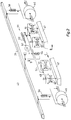
- FIG. 1 shows a cylinder 1 of a rotary printing press with easily bendable, arcuate objects 2, preferably printing plates 2.
- each of the easily bendable, arcuate objects 2, front and rear hook-in edges 3, 4 are arranged at their opposite ends, the respective legs 6, 7 of which enclose an opening angle alpha of less than 90 °.
- These hook-in folds 3, 4 are designed to be dimensionally stable, ie when the objects 2 are clamped on the cylinder 1, these hook-in folds 3, 4 are not bent open.
- This object 2 designed in this way can also consist of printing rubber blankets which are provided with hooked-in folds 3, 4.
- These dimensionally stable hook-in folds 3, 4 of the printing rubber blankets can be folded ends of a metal plate on which the printing rubber blanket has been firmly bonded, for example glued or vulcanized.
- the fabric inserts of the printing rubber blanket can be made of CFRP (carbon fiber reinforced plastic) or GRP (glass fiber reinforced plastic) and the hooked-in folds 3, 4 can be formed therefrom. The following simplifies this described object called pressure plate 2.
- the cylinder 1 of the rotary printing press which is mounted in two side frames 8, 9, is associated with an inking unit protection 11 which is close to the cylinder and is designed as a first printing plate preparation device 12.
- This pressure plate supply device 12 has an upper and a lower, the upper opposite wall 13, 14, which together form a shaft 16.
- the plate cylinder-near end 17 of the upper wall 13 is formed approximately parallel to a tangent 21, which is determined by a cylindrical surface 22 of the cylinder 1 and the hanging bar 19 of the printing plate preparation device 12.
- a second printing plate preparation device 23 can be arranged, the end 24 near the plate cylinder of which is also provided with a hooking strip 26 with a nose-shaped cross section and approximately parallel to that of Cylinder jacket surface 22 of the cylinder 1 and the hanging bar 19 of the first printing plate preparation device 12 fixed tangent 21 is formed.
- a right and left linear drive 27, 28 is fastened in the side frames 8, 9, which consists, for example, of threaded spindles 29, 31 which are rotatably mounted in blocks 32, 33, 34, 36 fixed to the frame.
- other known linear drives 27, 28, such as. B. belt or chain drives, rack and pinion drives, hydraulic or pneumatic servo cylinders or linear motors can be used.
- Via a belt 37, e.g. B. timing belt which mechanically synchronizes the right and left threaded spindles 29, 31, a synchronous rotary movement of the threaded spindles 29, 31 is generated by a drive 38.
- This synchronization can take place mechanically, for example, via chain or cardan shafts or electronically via two separate drives 38 of the linear drives 27, 28.
- the two threaded spindles 29, 31 move a traverse 39 parallel to the axis of rotation 18 of the cylinder 1 in a transport plane 41 which lies above and approximately parallel to the tangent 21 determined by the cylinder surface 22 of the cylinder 1 and the hooking bar 19 of the printing plate preparation device 12.
- threaded nuts 42 are arranged so that the Traverse 39 is operatively connected at right angles to the threaded spindles 29, 31.
- At least one gripping and pressing device 43 is attached along this traverse 39; in the example shown, four gripping and pressing devices 43 are fastened.
- Each individual pressure plate 2 belonging to an axial cylinder section is assigned an independently actuable gripping and pressing device 43.
- an additional linear drive by means of which a single gripping and pressing device 43 executes an axial movement along the crossmember 39, to change a plurality of printing plates 2 arranged along the cylinder 1 with only a single gripping and pressing device 43.
- a gripping and pressing device 43 consists of at least one gripper unit 44 and at least one pressure roller 46.
- This gripper unit 44 and the pressure rollers 46 are independent of the cylinder 1 in the radial direction "D", the gripper unit 44 also in the axial direction "C” displaceable from one another by positioning devices.
- the gripping and pressing device 43 is approximately symmetrical to the center line running in the cylinder circumferential direction Pressure plate 2 set up:
- Each gripping and pressing device 43 is a gripper unit 44 in the form of z.
- two suction strips 47 are formed which are perpendicular to a guide bar 48 against rotation tangential direction "B" of the cylinder 1 and are pressed by compression springs 49 in the direction "B" against a stop 51.
- These guide strips 48 are fastened to a further guide strip 52 and can be displaced in the opposite direction "C” by a positioning drive 53.
- a pneumatic cylinder 54 changes the position of the guide bar 52 with the suction bars 47 along the direction "D".
- a pressure roller 46 which can be placed against the pressure plate 2 against the direction "D” by means of a pneumatic cylinder 56.
- the positioning drive 53 can be designed, for example, as a stepper motor with a threaded spindle. An electric motor with interacting incremental encoders or potentiometers is also possible. Thus, means for detecting its position or the position of the pressure plate 2 preferably cooperate with the positioning drive 53.
- closures 57, 58, 59, 61 arranged in the cylinder 1 in the axial direction, parallel to the axis of rotation 18 of the Cylinder 1 in cylinder pits 62.
- the length of the closures 57, 58, 59, 61 is in each case approximately half the cylinder length.
- These closures 57, 58, 59, 61 are again subdivided into plate width (ie two printing plates 2 are provided for each closure 57, 58, 59, 61) and can be actuated independently both within this subdivision and among themselves.
- the closures 57, 58 are offset from one another by approximately 90 ° in the circumferential direction of the cylinder 1.
- Each closure 57, 58 is assigned a closure 59, 61 opposite each other.
- the cylinder 1 rotates into a clamping position, which is determined by the fact that the center line of the closure 57 is approximately congruent with the solder 81 dropped from the axis of rotation 18 onto the perpendicular 81 to the direction of movement of the linear drives 27, 28.
- the cross member 39 is brought into position by means of the two linear drives 27, 28 for receiving the new pressure plate 84, i. H.
- the suction strips 47 are located in the area of the end 17 of the printing plate supply device 12 near the plate cylinder.
- the gripper unit 44 is displaced in the direction "C".
- the newly applied pressure plate 84 was on the upper wall 13 and on the hanging bar 19 Printing plate supply device 12 placed pre-positioned.
- the suction strips 47 are lowered to the level of the pressure plate 84 by venting the pneumatic cylinder 54 and acted upon by suction air.
- the printing plate 84 is fixed with its printing side to the gripping and pressing device 43.
- At least two side register stops 86, 66 are assigned to each of a plurality of pressure plates 84 lying axially next to one another. At least one of these two side register stops 66, 86 can be arranged directly on the hanging bar 19 of the printing plate preparation device 12 or else separately in an area between the printing plate preparation device 12 and the cylinder 1 (FIG. 3).
- a second side register stop 66 is arranged on the hanging bar 19. This side register stop 66 is laterally offset and finely adjustable in the axial direction of the cylinder 1 arranged.
- a side register stop 86 on the cylinder 1 is dispensed with.
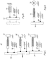
- the side register device 67 arranged in the area between the printing plate preparation device 12 and cylinder 1 consists of three successively arranged side register stops 68, 69, 71, which are arranged in a stepped manner in relation to one another in the axial direction of the cylinder 1 (FIG. 4).
- These side register stops 68, 69, 71 are each finely adjustable, for example, by means of a threaded screw 91, 92, 93 and a linear bearing 94, 96, 97.
- only one side register stop 72, 74 is displaceably arranged in a bearing 98, 99, wherein this can be brought into different positions offset from one another in the axial direction of the cylinder 1.
- the side register stop 72 can be attached to a stationary working cylinder 73 (FIG. 5). A piston of this working cylinder 73 moves the side register stop 72 in two positions.
- a side register stop 74 in a continuously adjustable manner in the axial direction of the cylinder 1.
- the side register stop 74 can be positioned, for example, by means of a threaded spindle 77 driven by an electric motor 76 (Fig. 6).
- the pressure plate 84 is axially aligned as follows at the side register stops 66-69, 71, 72, 74: If a plurality of side register stops 66-69, 71, 86 are arranged one behind the other as in the first and second exemplary embodiments, the gripping and pressing device 43 moves with the gripped pressure plate 84 in the direction “B” a preselected one which is assigned to the desired side register stop 66-69, 71, 86 Position.
- the side register stop 72, 74 is adjustable, the side register stop 72, 74 is brought into the preselected position, for example by means of the working cylinder 73 or electric motor 76.
- the gripper unit 44 moves with the gripped pressure plate 88 into a position assigned to the side register stop in the direction "A".
- the positioning drive 53 moves the gripper unit 44 in the axial direction until the pressure plate 84 with its hooked-in bend 3 is pressed against the respective side register stop 66-69, 71, 72, 74, 86.
- the positioning drive 53 is then switched off. This can be done, for example, by limiting the current consumption of an electrically driven positioning drive 53 or it can also be a sensor in the area of the power flow Determination of the contact pressure may be arranged. It is also possible to determine a switch-off criterion from the relationship between the distance traveled and the time required for this by the pressure plate 84 or the positioning drive 53.
- sensors for detecting the position of the pressure plate 84 can also be provided.
- a CCD sensor is suitable for determining the position of the pressure plate 84 and for controlling the position drive 53 of the gripper unit 44.
- This CCD sensor can advantageously be partially covered from the side edge of the pressure plate 84 and fixed in place with respect to the side frame. The CCD sensor is aligned with a specific position of the cylinder 1.
- the starting position of the pressure plate 84 is determined by means of the CCD sensor. Starting from this starting position, the positioning drive 53 is actuated until the pressure plate 84 has reached the desired position with respect to the CCD sensor and thus with respect to the cylinder 1. The positioning drive 53 is now switched off and the pressure plate 84 is transported in the direction of cylinder 1.
- Another embodiment, not shown has two sensors for position detection on the gripping and pressing device 43 and a reference point on the cylinder 1.
- the first sensor which detects a side edge of the pressure plate 84, is fastened to the cross member 39 in the region of a side edge of the pressure plate 84.
- the second sensor which detects the reference point, is arranged to be movable with the gripper unit 44 in the region of the reference point located on the cylinder 1.
- the gripper unit 44 with the second sensor is moved in the axial direction until the reference point of the cylinder 1 is reached. This reference position is stored by the control of the positioning drive 53.
- the control of the positioning drive 53 calculates a distance by which the pressure plate 84 can still be displaced. The positioning drive 53 then performs the necessary axial movement of the pressure plate 84.
- the reference point is on the cylinder 1 as a stop for a side edge of the pressure plate 84 educated.
- the pressure plate 84 suspended in the suspension strip 63 of the cylinder 1 is held with its suspension fold 3 by the gripper device 44 by means of the positioning drive 53 in the axial direction against the stop. If the hooked-in bend 3 abuts the stop, the positioning drive 53 switches off. This shutdown can take place, for example, by means of a current limiter or by evaluating pulse sequences from an incremental encoder.
- the pressure plate 84 is positioned by means of the positioning drive 53 at the preselected position of the cylinder 1 in the axial direction.
- At least one cylinder section has a plurality of selectable target positions lying next to one another.
- Each cylinder section to which a pressure plate is assigned is assigned a plurality of selectable target positions lying next to one another.
- the "rough position" of the plate is thus determined by the selection of the cylinder section.
- the "fine position" is determined by selecting a target position from a plurality of target positions lying next to one another in the axial direction.
Landscapes
- Supply, Installation And Extraction Of Printed Sheets Or Plates (AREA)
- Exposure And Positioning Against Photoresist Photosensitive Materials (AREA)
Abstract
Bei einer Vorrichtung und einem Verfahren zum axialen Positionieren einer Druckplatte (84) besteht die Aufgabe darin, Seitenpasserabweichungen infolge unterschiedlicher Druckaufträge zu minimieren. Erfindungsgemäß wird dies dadurch erreicht, daß die Druckplatte (84) während der Montage in vorwählbare Positionen in axialer Richtung (6) positioniert wird. <IMAGE>In an apparatus and a method for axially positioning a printing plate (84), the task is to minimize page registration deviations due to different print jobs. This is achieved according to the invention in that the pressure plate (84) is positioned in preselectable positions in the axial direction (6) during assembly. <IMAGE>
Description
Die Erfindung betrifft ein Verfahren und eine Vorrichtung zum axialen Positionieren einer Druckplatte gemäß den Oberbegriffen der Ansprüche 1 und 6.The invention relates to a method and a device for axially positioning a pressure plate according to the preambles of
Die DE 28 04 970 A1 beschreibt eine Einrichtung zur Montage und Demontage von Druckplatten in einer Rotationsdruckmaschine.
Dabei führt ein Saugorgan eine lineare Bewegung zwischen einer Abgabewalze und einem Plattenzylinder aus und transportiert damit die Druckplatte.
Zwischen Abgabewalze und Plattenzylinder befindet sich ein Positioniertisch auf den das Saugorgan die Platte ablegt. Der Positioniertisch positioniert die Platte, worauf diese wieder von dem Saugorgan ergriffen wird und weiter zum Plattenzylinder transportiert wird.DE 28 04 970 A1 describes a device for assembling and disassembling printing plates in a rotary printing press.
A suction element performs a linear movement between a delivery roller and a plate cylinder and thus transports the printing plate.
Between the delivery roller and the plate cylinder there is a positioning table on which the suction element places the plate. The positioning table positions the plate, whereupon it is gripped again by the suction element and transported further to the plate cylinder.
Nachteilig ist an dieser Einrichtung, daß bei der Aufnahme der positionierten Platte durch das Saugorgan Fehler entstehen können und die Platte nur in eine, nicht vorwählbare Position gebracht werden kann.A disadvantage of this device is that errors can occur when the positioned plate is received by the suction element and the plate can only be brought into a position that cannot be preselected.
Der Erfindung liegt die Aufgabe zugrunde, ein Verfahren und eine Vorrichtung zum axialen Positionieren einer Druckplatte auf einem Plattenzylinder zu schaffen.The invention has for its object to provide a method and an apparatus for axially positioning a printing plate on a plate cylinder.
Diese Aufgabe wird erfindungsgemäß durch ein Verfahren und eine Vorrichtung mit den Merkmalen der Ansprüche 1 und 6 gelöst.This object is achieved according to the invention by a method and a device with the features of
In vorteilhafter Weise kann mit dem erfindungsgemäßen Verfahren bzw. der Vorrichtung eine Druckplatte in verschiedenen Positionen registergenau auf den Plattenzylinder montiert werden.
Damit kann das sogenannte Fan-Out-Phänomen kompensiert werden. Unter dem Fan-Out-Phänomen wird die axiale Passerabweichung eines zu druckenden Bildpunktes im Mehrfarbendruck von Druckstelle zu Druckstelle auf einer Materialbahn bezeichnet. Diese Passerabweichung ist beispielsweise abhängig von der Grammatur und den Eigenschaften (Penetrationsverhalten, Typ) der Papierbahn, der Art des zu druckenden Sujets und der Druckgeschwindigkeit. Dies hat zur Folge, daß axiale Passerabweichungen bei unterschiedlichen Druckaufträgen verschieden groß sein können. Um diese Passerabweichungen zu kompensieren, werden bisher Seitenregisteranschläge, die axial nebeneinander liegenden Druckplatten zugeordnet sind, entsprechend eingestellt.
Mit der erfindungsgemäßen Vorrichtung ist es möglich, unterschiedliche Positionen ferngesteuert vorzuwählen und die Druckplatte entsprechend auf dem Zylinder zu positionieren. Dadurch werden aufwendige manuelle Einstellarbeiten der Seitenregisteranschläge vermieden.Advantageously, with the method and the device according to the invention, a printing plate can be mounted in register register on the plate cylinder in different positions.
This can be used to compensate for the so-called fan-out phenomenon. The fan-out phenomenon describes the axial register deviation of a pixel to be printed in multi-color printing from printing point to printing point on a material web. This register deviation depends, for example, on the grammage and the properties (penetration behavior, type) of the paper web, the type of subject to be printed and the printing speed. As a result, axial register deviations can be of different sizes for different print jobs. In order to compensate for these register deviations, side register stops which are assigned axially adjacent printing plates have been set accordingly.
With the device according to the invention it is possible to preselect different positions remotely and to position the pressure plate accordingly on the cylinder. This avoids time-consuming manual adjustments to the side register stops.
Ist ein Referenzpunkt zur Detektion der Position der Druckplatte auf dem Zylinder angeordnet, werden Ungenauigkeiten infolge des Transportes der Druckplatte mittels der Transportmittel reduziert.If a reference point for the detection of the position of the printing plate on the cylinder is arranged, inaccuracies due to the transport of the printing plate by means of the transport means are reduced.
Die erfindungsgemäße Vorrichtung ist in der Zeichnung dargestellt und wird im folgenden näher beschrieben.The device according to the invention is shown in the drawing and is described in more detail below.
Es zeigen
- Fig. 1
- eine schematische Darstellung in Draufsicht einer Vorrichtung zur Montage von Druckplatten,
- Fig. 2
- eine schematische Darstellung einer Greif- und Andrückeinrichtung der Vorrichtung aus Fig. 1,
- Fig. 3
- eine schematische Seitenansicht der Vorrichtung mit zugehörigem Zylinder und Bereitstellungseinrichtungen aus Fig. 1,
- Fig. 4
- eine schematische Draufsicht auf eine Seitenregistereinrichtung gemäß einem zweiten Beispiel,
- Fig. 5
- eine schematische Draufsicht auf einen verstellbaren Seitenregisteranschlag gemäß einem dritten Beispiel,
- Fig. 6
- eine schematische Draufsicht auf einen verstellbaren Seitenregisteranschlag gemäß einem vierten Beispiel.
- Fig. 1
- 1 shows a schematic illustration in plan view of a device for mounting printing plates,
- Fig. 2
- 1 shows a schematic illustration of a gripping and pressing device of the device from FIG. 1,
- Fig. 3
- 2 shows a schematic side view of the device with associated cylinder and preparation devices from FIG. 1,
- Fig. 4
- 2 shows a schematic top view of a page register device according to a second example,
- Fig. 5
- 2 shows a schematic top view of an adjustable side register stop according to a third example,
- Fig. 6
- a schematic plan view of a adjustable side register stop according to a fourth example.
Fig. 1 zeigt einen Zylinder 1 einer Rotationsdruckmaschine mit leicht biegbaren, bogenförmigen Gegenständen 2, vorzugsweise Druckplatten 2.1 shows a
An jedem leicht biegbaren, bogenförmigen Gegenstand 2 sind an dessen gegenüberliegenden Enden jeweils vordere und hintere Einhängeabkantungen 3, 4 angeordnet, deren jeweilige Schenkel 6, 7 einen Öffnungswinkel Alpha kleiner als 90° einschließen. Diese Einhängeabkantungen 3, 4 sind formstabil ausgebildet, d. h. beim Spannen der Gegenstände 2 auf dem Zylinder 1 werden diese Einhängeabkantungen 3, 4 nicht aufgebogen. Dieser derart gestaltete Gegenstand 2 kann auch aus Druckgummitüchern, die mit Einhängeabkantungen 3, 4 versehen sind, bestehen.
Diese formstabilen Einhängeabkantungen 3, 4 der Druckgummitücher können abgekanteten Enden einer Metallplatte sein, auf der das Druckgummituch stoffschlüssig befestigt, beispielsweise geklebt oder vulkanisiert wurde. Auch können insbesondere die Gewebeeinlagen des Druckgummituches aus CFK (Kohlefaser verstärkter Kunststoff) oder GFK (Glasfaser verstärkter Kunststoff) gefertigt und daraus die Einhängeabkantungen 3, 4 geformt sein. Vereinfachend wird im folgenden dieser beschriebene Gegenstand Druckplatte 2 genannt.On each of the easily bendable,
These dimensionally stable hook-in folds 3, 4 of the printing rubber blankets can be folded ends of a metal plate on which the printing rubber blanket has been firmly bonded, for example glued or vulcanized. In particular, the fabric inserts of the printing rubber blanket can be made of CFRP (carbon fiber reinforced plastic) or GRP (glass fiber reinforced plastic) and the hooked-in folds 3, 4 can be formed therefrom. The following simplifies this described object called
Dem Zylinder 1 der Rotationsdruckmaschine, der in zwei Seitengestellen 8, 9 gelagert ist, ist ein zylindernaher, gestellfester Farbwerkschutz 11 zugeordnet, der als eine erste Druckplatten-Bereitstellungseinrichtung 12 ausgebildet ist.
Diese Druckplatten-Bereitstellungseinrichtung 12 weist eine obere und eine untere, der oberen gegenüberliegenden Wand 13, 14 auf, die zusammen einen Schacht 16 bilden. An einem plattenzylindernahen Ende 17 der oberen Wand 13 ist eine sich über die Breite des Zylinders 1 erstreckende, parallel zu einer Drehachse 18 des Zylinders 1 verlaufende Einhängeleiste 19 mit nasenförmigem Querschnitt angebracht. Das plattenzylindernahe Ende 17 der oberen Wand 13 ist annähernd parallel zu einer Tangente 21, die von einer Zylindermantelfläche 22 des Zylinders 1 und der Einhängeleiste 19 der Druckplatten-Bereitstellungseinrichtung 12 bestimmt wird, ausgebildet.The
This pressure
Neben der ersten Druckplatten-Bereitstellungseinrichtung 12 kann wie im vorliegenden Beispiel eine zweite Druckplatten-Bereitstellungseinrichtung 23 angeordnet sein, deren plattenzylindernahes Ende 24 ebenfalls mit einer Einhängeleiste 26 mit nasenförmigen Querschnitt versehen ist und annähernd parallel zu der von Zylindermantelfläche 22 des Zylinders 1 und der Einhängeleiste 19 der ersten Druckplatten-Bereitstellungseinrichtung 12 festgelegten Tangente 21 ausgebildet ist.In addition to the first printing
Oberhalb und parallel zu dieser Tangente 21 ist in den Seitengestellen 8, 9 jeweils eine rechter und linker Linearantrieb 27, 28 befestigt, der beispielsweise jeweils aus Gewindespindeln 29, 31 die drehbar in gestellfesten Böcken 32, 33, 34, 36 gelagert sind, besteht. Ebenso können andere bekannte Linearantriebe 27, 28, wie z. B. Riemen- bzw. Kettenantriebe, Zahnstangenantriebe, hydraulische bzw. pneumatische Servozylinder oder Linearmotoren eingesetzt werden. Über einen Riemen 37, z. B. Zahnriemen, der die rechte und linke Gewindespindel 29, 31 mechanisch synchronisiert, wird durch einen Antrieb 38 eine synchrone Drehbewegung der Gewindespindeln 29, 31 erzeugt. Diese Synchronisation kann beispielsweise mechanisch auch über Ketten- oder Gelenkwellen oder elektronisch über zwei getrennte Antriebe 38 der Linearantriebe 27, 28 erfolgen. Die beiden Gewindespindeln 29, 31 bewegen eine zur Drehachse 18 des Zylinders 1 parallele Traverse 39 in einer Transportebene 41, die oberhalb und annähernd parallel zur von Zylindermantelfläche 22 des Zylinders 1 und Einhängeleiste 19 der Druckplatten-Bereitstellungseinrichtung 12 bestimmten Tangente 21 liegt. An den beiden Enden dieser Traverse 39 sind jeweils Gewindemuttern 42 angeordnet, so daß die Traverse 39 rechtwinklig mit den Gewindespindeln 29, 31 in Wirkverbindung steht. Entlang dieser Traverse 39 ist mindestens eine Greif- und Andrückeinrichtung 43, im dargestellten Beispiel sind vier Greif- und Andrückeinrichtungen 43 befestigt.Above and parallel to this tangent 21, a right and left
Jeder einzelnen, einem axialen Zylinderabschnitt zugehörigen Druckplatte 2 ist eine unabhängig betätigbare Greif- und Andrückeinrichtung 43 zugeordnet. Ebenso ist es aber auch möglich mit einem zusätzlichen Linearantrieb, durch den eine einzige Greif- und Andrückeinrichtung 43 eine axiale Bewegung entlang der Traverse 39 ausführt, mehrere entlang des Zylinders 1 angeordnete Druckplatten 2 mit nur einer einzigen Greif- und Andrückeinrichtung 43 zu wechseln.Each
In Fig. 2 sind die Elemente einer Greif- und Andrückeinrichtung 43 dargestellt:
Eine Greif- und Andrückeinrichtung 43 besteht aus mindestens einer Greifereinheit 44 und mindestens einer Andrückrolle 46. Diese Greifereinheit 44 und die Andrückrollen 46 sind bezüglich des Zylinders 1 in radialer Richtung "D", die Greifereinheit 44 zusätzlich noch in axialer Richtung "C", unabhängig voneinander durch Positioniereinrichtungen verschiebbar.The elements of a gripping and
A gripping and
Im vorliegenden Beispiel ist die Greif- und Andrückeinrichtung 43 annähernd symmetrisch zur in Zylinderumfangsrichtung verlaufenden Mittellinie der Druckplatte 2 aufgebaut:
Je Greif- und Andrückeinrichtung 43 ist eine Greifereinheit 44 in Form von z. B. zwei Saugleisten 47 ausgebildet, die senkrecht zu einer Führungsleiste 48 verdrehgesichert entgegen tangentialer Richtung "B" des Zylinders 1 verschiebbar sind und durch Druckfedern 49 in Richtung "B" gegen einen Anschlag 51 gedrückt werden.In the present example, the gripping and
Each gripping and
Diese Führungsleisten 48 sind an einer weiteren Führungsleiste 52 befestigt und durch einen Positionierantrieb 53 entgegen Richtung "C" verschiebbar. Ein Pneumatikzylinder 54 bewirkt eine Positionsveränderung der Führungsleiste 52 mit den Saugleisten 47 entlang der Richtung "D". Neben den Saugleisten 47 befindet sich jeweils eine Andrückrolle 46, die über einen Pneumatikzylinder 56 entgegen Richtung "D" auf die Druckplatte 2 angestellt werden kann.These guide strips 48 are fastened to a
Der Positionierantrieb 53 kann beispielsweise als Schrittmotor mit Gewindespindel ausgeführt sein. Auch ist ein Elektromotor mit zusammenwirkenden Inkrementalgeber oder Potentiometer möglich.
Vorzugsweise wirken also mit dem Positionierantrieb 53 Mittel zum Detektieren seiner Stellung oder der Stellung der Druckplatte 2 zusammen.The
Thus, means for detecting its position or the position of the
Im vorliegenden Beispiel sind in dem Zylinder 1 in axialer Richtung, parallel zur Drehachse 18 des Zylinders 1 in Zylindergruben 62 verlaufend, vier Verschlüsse 57, 58, 59, 61 angeordnet. Die Länge der Verschlüsse 57, 58, 59, 61 beträgt jeweils ca. halbe Zylinderlänge. Diese Verschlüsse 57, 58, 59, 61 sind nochmals auf Plattenbreite unterteilt (d. h. pro Verschluß 57, 58, 59, 61 sind jeweils zwei Druckplatten 2 vorgesehen) und sind sowohl innerhalb dieser Unterteilung als auch untereinander unabhängig betätigbar. Die Verschlüsse 57, 58 sind in Umfangsrichtung des Zylinders 1 um ca. 90° zueinander versetzt. Jedem Verschluß 57, 58 ist jeweils ein Verschluß 59, 61 gegenüberliegend zugeordnet.In the present example, in the
Zum Aufspannen einer neuen Druckplatte 84 dreht der Zylinder 1 in eine Aufspannposition, die dadurch bestimmt wird, daß die Mittellinie des Verschlusses 57 annähernd deckungsgleich mit dem von der Drehachse 18 auf die senkrecht zur Bewegungsrichtung der Linearantriebe 27, 28 gefällten Lot 81 ist. Die Traverse 39 wird mittels der beiden Linearantriebe 27, 28 in Position zur Aufnahme der neuen Druckplatte 84 gebracht, d. h. die Saugleisten 47 stehen in Bereich des plattenzylindernahen Endes 17 der Druckplatten-Bereitstellungseinrichtung 12. Durch Betätigen des Positionierantriebes 53 wird die Greifereinheit 44 entgegen Richtung "C" verschoben.To clamp a
Die neu aufzubringende Druckplatte 84 wurde auf der oberen Wand 13 und an der Einhängeleiste 19 der Druckplatten-Bereitstellungseinrichtung 12 vorpositioniert aufgelegt.The newly applied
Die Saugleisten 47 werden durch Entlüften des Pneumatikzylinders 54 auf das Niveau der Druckplatte 84 abgesenkt und mit Saugluft beaufschlagt. Dadurch wird die Druckplatte 84 mit ihrer druckenden Seite an der Greif- und Andrückeinrichtung 43 fixiert.The suction strips 47 are lowered to the level of the
Zur axialen Ausrichtung einer Druckplatte 84 sind beispielsweise folgende Mittel vorgesehen:The following means are provided, for example, for the axial alignment of a pressure plate 84:
In einem ersten Ausführungsbeispiel sind jeder von mehreren axial nebeneinander liegenden Druckplatten 84 mindestens zwei Seitenregisteranschläge 86, 66 zugeordnet. Mindestens einer dieser beiden Seitenregisteranschläge 66, 86 kann direkt an der Einhängeleiste 19 der Druckplatten-Bereitstellungseinrichtung 12 oder auch separat in einem Bereich zwischen der Druckplatten-Bereitstellungseinrichtung 12 und dem Zylinder 1 angeordnet sein (Fig. 3).In a first exemplary embodiment, at least two side register stops 86, 66 are assigned to each of a plurality of
Im einfachsten Fall ist zusätzlich zu dem üblicherweise auf dem Zylinder 1 vorhandenen Seitenregisteranschlag 86 ein zweiter Seitenregisteranschlag 66 an der Einhängeleiste 19 angeordnet. Dieser Seitenregisteranschlag 66 ist in axialer Richtung des Zylinders 1 seitlich versetzt und feinjustierbar angeordnet.In the simplest case, in addition to the
In einem zweiten Ausführungsbeispiel wird auf einen Seitenregisteranschlag 86 auf dem Zylinder 1 verzichtet. Die in dem Bereich zwischen Druckplatten-Bereitstellungseinrichtung 12 und Zylinder 1 angeordnete Seitenregistereinrichtung 67 besteht aus drei nacheinander angeordneten Seitenregisteranschlägen 68, 69, 71, die in axialer Richtung des Zylinders 1 zueinander stufenartig versetzt angeordnet sind (Fig.4). Diese Seitenregisteranschläge 68, 69, 71 sind beispielsweise jeweils mittels einer Gewindeschraube 91, 92, 93 und eines Linearlagers 94, 96, 97 feinjustierbar ausgeführt.In a second exemplary embodiment, a
In einem dritten und vierten Ausführungsbeispiel ist jeweils nur ein Seitenregisteranschlag 72, 74 in einem Lager 98, 99 verschiebbar angeordnet, wobei dieser in verschiedene, in axialer Richtung des Zylinders 1 zueinander versetzte Positionen bringbar ist.
Beispielsweise kann der Seitenregisteranschlag 72 an einem ortsfest angeordneten Arbeitszylinder 73 befestigt sein (Fig. 5). Ein Kolben dieses Arbeitszylinders 73 bewegt den Seitenregisteranschlag 72 in zwei Stellungen. Auch ist es möglich einen Seitenregisteranschlag 74 in axialer Richtung des Zylinders 1 stufenlos verstellbar anzuordnen. Dazu kann der Seitenregisteranschlag 74 beispielsweise mittels einer von einem Elektromotor 76 angetriebenen Gewindespindel 77 positioniert werden (Fig. 6).In a third and fourth exemplary embodiment, only one
For example, the
Die Druckplatte 84 wird folgendermaßen an den Seitenregisteranschlägen 66-69, 71, 72, 74 axial ausgerichtet:
Sind mehrere Seitenregisteranschläge 66-69, 71, 86 wie im ersten und zweiten Ausführungsbeispiel hintereinander angeordnet, fährt die Greif- und Andrückeinrichtung 43 mit der ergriffenen Druckplatte 84 in Richtung "B" eine vorgewählte, dem gewünschten Seitenregisteranschlag 66-69, 71, 86 zugeordnete Position an.The
If a plurality of side register stops 66-69, 71, 86 are arranged one behind the other as in the first and second exemplary embodiments, the gripping and
Bei verstellbarem Seitenregisteranschlag 72, 74 wird der Seitenregisteranschlag 72, 74 beispielsweise mittels des Arbeitszylinders 73 oder Elektromotors 76 in die vorgewählte Position gebracht. Die Greifereinheit 44 fährt mit der ergriffenen Druckplatte 88 in eine dem Seitenregisteranschlag zugeordnete Position in Richtung "A".When the
Der Positionierantrieb 53 bewegt die Greifereinheit 44 in axialer Richtung bis die Druckplatte 84 mit ihrer Einhängeabkantung 3 gegen den jeweiligen Seitenregisteranschlag 66-69, 71, 72, 74, 86 gedrückt wird. Anschließend wird der Positionierantrieb 53 abgestellt. Dies kann beispielsweise durch eine Begrenzung der Stromaufnahme eines elektrisch angetriebenen Positionierantriebes 53 erfolgen oder es kann auch ein Sensor im Bereich des Kraftflusses zur Ermittlung der Anpreßkraft angeordnet sein. Ebenso ist es möglich aus der Beziehung zwischen zurückgelegtem Weg und dafür benötigter Zeit der Druckplatte 84 oder des Positionierantriebes 53 ein Kriterium für die Abschaltung zu ermitteln.The positioning drive 53 moves the
Anstelle der Seitenregisteranschläge 66-69, 71, 72, 74, 86 können auch Sensoren zur Detektion der Position der Druckplatte 84 vorgesehen sein. Insbesondere eignet sich ein CCD-Sensor zur Postionsbestimmung der Druckplatte 84 und zur Steuerung des Postionierantriebes 53 der Greifereinheit 44. Dieser CCD-Sensor kann vorteilhaft von der Seitenkante der Druckplatte 84 teilweise überdeckend und bezüglich des Seitengestells ortsfest befestigt. Dabei ist der CCD-Sensor bezüglich einer bestimmten Position des Zylinders 1 zugeordnet ausgerichtet.Instead of the side register stops 66-69, 71, 72, 74, 86, sensors for detecting the position of the
Nachdem die Greifereinheit die Druckplatte 84 ergriffen hat, wird mittels des CCD-Sensors die Ausgangsposition der Druckplatte 84 ermittelt. Von dieser Ausgangsposition ausgehend wird der Positionierantrieb 53 betätigt, bis die Druckplatte 84 die gewünschte Position bezüglich des CCD-Sensors und damit bezüglich des Zylinders 1 erreicht hat. Der Positionierantrieb 53 wird nun abgeschaltet und die Druckplatte 84 wird in Richtung Zylinder 1 transportiert.After the gripper unit has gripped the
Eine weiteres, nicht dargestelltes Ausführungsbeispiel weist zwei Sensoren zur Positionserkennung an der Greif- und Andrückeinrichtung 43 und einen Referenzpunkt auf dem Zylinder 1 auf. Der erste, eine Seitenkante der Druckplatte 84 detektierende Sensor ist an der Traverse 39 im Bereich einer Seitenkante der Druckplatte 84 befestigt. Der zweite, den Referenzpunkt detektierende Sensor ist mit der Greifereinheit 44 bewegbar im Bereich des auf dem Zylinder 1 befindlichen Referenzpunkt angeordnet.
Die Greifereinheit 44 mit dem zweiten Sensor wird solange in axialer Richtung bewegt, bis der Referenzpunkt des Zylinders 1 erreicht ist. Diese Referenzposition wird von der Steuerung des Positionierantriebes 53 gespeichert. Wurde während dieser Bewegung von dem ersten Sensor die Position der Seitenkante der Druckplatte 84 erkannt, wird auch diese Position gespeichert, ansonsten wird die Druckplatte 84 solange weiter axial verschoben, bis die Seitenkante der Druckplatte 84 detektiert wurde. Aufgrund dieser beiden Positionswerte und einer vorgewählten Position, in der die Druckplatte 84 montiert werden soll, errechnet die Steuerung des Positionierantriebes 53 eine Wegstrecke, um die die Druckplatte 84 noch zu verschieben ist. Der Positionierantrieb 53 führt anschließend die notwendige axiale Bewegung der Druckplatte 84 aus.Another embodiment, not shown has two sensors for position detection on the gripping and
The
Schließlich ist in einem weiteren, nicht dargestellten Ausführungsbeispiel auf dem Zylinder 1 der Referenzpunkt als Anschlag für eine Seitenkante der Druckplatte 84 ausgebildet. Die in der Einhängeleiste 63 des Zylinders 1 eingehängte Druckplatte 84 wird mit ihrer Einhängeabkantung 3 von Greifereinrichtung 44 gehalten mittels des Positionierantriebes 53 in axialer Richtung gegen den Anschlag geführt. Stößt die Einhängeabkantung 3 gegen den Anschlag schaltet der Positionierantrieb 53 ab. Diese Abschaltung kann beispielsweise mittels Strombegrenzer oder durch Auswertung von Impulsfolgen eines Inkrementalgebers erfolgen. Von dieser Referenzposition ausgehend, wird die Druckplatte 84 mittels des Positionierantriebes 53 an die vorgewählte Position des Zylinders 1 in axialer Richtung positioniert.Finally, in a further exemplary embodiment, not shown, the reference point is on the
Die weitere Montage kann beispielsweise entsprechend dem in der DE 44 24 931 A1 beschriebenen Verfahren erfolgen.Further assembly can take place, for example, in accordance with the method described in
Sind auf einem Zylinder in axialer Richtung mehrere Druckplatten in zugeordneten Zylinderabschnitten nebeneinander montierbar, so weist mindestens ein Zylinderabschnitt mehrere nebeneinander liegende wählbare Sollpositionen auf. Jedem Zylinderabschnitt, dem eine Druckplatte zugeordnet ist, sind mehrere nebeneinanderliegende wählbare Sollpositionen zugeordnet. Durch die Auswahl des Zylinderabschnittes wird also die "Grobposition" der Platte festgelegt. Innerhalb des Zylinderabschnitts wird durch Auswahl einer Sollposition aus mehreren in axialer Richtung nebeneinanderliegenden Sollpositionen die "Feinposition" festgelegt.If a plurality of pressure plates can be mounted next to one another in the associated cylinder sections on a cylinder in the axial direction, then at least one cylinder section has a plurality of selectable target positions lying next to one another. Each cylinder section to which a pressure plate is assigned is assigned a plurality of selectable target positions lying next to one another. The "rough position" of the plate is thus determined by the selection of the cylinder section. Within the cylinder section, the "fine position" is determined by selecting a target position from a plurality of target positions lying next to one another in the axial direction.
- 11
- Zylindercylinder
- 22nd
- Druckplatte (biegbarer, bogenförmiger Gegenstand)Pressure plate (bendable, arched object)
- 33rd
- Einhängeabkantung, vordere (2)Hook-in bend, front (2)
- 44th
- Einhängeabkantung, hintere (2)Insert folding, rear (2)
- 55
- --
- 66
- Schenkelleg
- 77
- Schenkelleg
- 88th
- Seitengestell, rechtesRight side frame
- 99
- Seitengestell, linkesSide frame, left
- 1010th
- --
- 1111
- FarbwerkschutzInking unit protection
- 1212th
- Druckplatten-Bereitstellungseinrichtung, erstePrinting plate preparation device, first
- 1313
- Wand, obere (12)Wall, upper (12)
- 1414
- Wand, untere (12)Wall lower (12)
- 1515
- --
- 1616
- Schacht (12)Manhole (12)
- 1717th
- Ende, plattenzylindernah (13)End, close to the plate cylinder (13)
- 1818th
- Drehachse (1)Axis of rotation (1)
- 1919th
- Einhängeleiste (12)Hanging rails (12)
- 2020th
- --
- 2121
- Tangente (1, 12)Tangent (1, 12)
- 2222
- Zylindermantelfläche (1)Cylinder surface (1)
- 2323
- Druckplatten-Bereitstellungseinrichtung, zweitePrinting plate preparation device, second
- 2424th
- Ende, plattenzylindernah (23)End, close to the plate cylinder (23)
- 2525th
- --
- 2626
- Einhängeleiste (23)Hanging rails (23)
- 2727
- Linearantrieb, rechterLinear drive, right
- 2828
- Linearantrieb, linkerLinear drive, left
- 2929
- Gewindespindel, rechte (27)Lead screw, right (27)
- 3030th
- --
- 3131
- Gewindespindel, linke (28)Left-hand lead screw (28)
- 3232
- BockBuck
- 3333
- BockBuck
- 3434
- BockBuck
- 3535
- --
- 3636
- BockBuck
- 3737
- Riemenbelt
- 3838
- Antriebdrive
- 3939
- Traversetraverse
- 4040
- --
- 4141
- TransportebeneTransport level
- 4242
- Gewindemutter (39)Threaded nut (39)
- 4343
- Greif- und AndrückeinrichtungGripping and pressing device
- 4444
- Greifereinheit (43)Gripper unit (43)
- 4545
- --
- 4646
- Andrückrolle (43)Pressure roller (43)
- 4747
- Saugleisten (44)Suction strips (44)
- 4848
- Führungsleiste (44)Guide bar (44)
- 4949
- Druckfeder (44)Compression spring (44)
- 5050
- --
- 5151
- Anschlag (44)Stop (44)
- 5252
- Führungsleiste (44)Guide bar (44)
- 5353
- PositionierantriebPositioning drive
- 5454
- Pneumatikzylinder (47)Pneumatic cylinder (47)
- 5555
- Gewindespindel (53)Lead screw (53)
- 5656
- Pneumatikzylinder (46)Pneumatic cylinder (46)
- 5757
- Verschluß (1)Closure (1)
- 5858
- Verschluß (1)Closure (1)
- 5959
- Verschluß (1)Closure (1)
- 6060
- --
- 6161
- Verschluß (1)Closure (1)
- 6262
- Zylindergrube (1)Cylinder pit (1)
- 6363
- Einhängeleiste, vordere (1)Hanging rails, front (1)
- 6464
- --
- 6565
- --
- 6666
- Seitenregisteranschlag, zweiterSide register stop, second
- 6767
- SeitenregistereinrichtungPage register facility
- 6868
- Seitenregisteranschlag (67)Side register stop (67)
- 6969
- Seitenregisteranschlag (67)Side register stop (67)
- 7070
- --
- 7171
- Seitenregisteranschlag (67)Side register stop (67)
- 7272
- SeitenregisteranschlagSide register stop
- 7373
- ArbeitszylinderWorking cylinder
- 7474
- SeitenregisteranschlagSide register stop
- 7575
- --
- 7676
- ElektromotorElectric motor
- 7777
- GewindespindelThreaded spindle
- 7878
- --
- 7979
- --
- 8080
- --
- 8181
- Lot (18, 29; 31)Lot (18, 29; 31)
- 8282
- AblösepunktRelease point
- 8383
- Tangente (82, 16)Tangent (82, 16)
- 8484
- Druckplatte, neu, erstePressure plate, new, first
- 8585
- --
- 8686
- SeitenregisteranschlagSide register stop
- 8787
- Schutzprotection
- 8888
- Druckplatte, neu, zweitePrinting plate, new, second
- 8989
- --
- 9090
- --
- 9191
- GewindeschraubeThreaded screw
- 9292
- GewindeschraubeThreaded screw
- 9393
- GewindeschraubeThreaded screw
- 9494
- LinearlagerLinear bearings
- 9595
- --
- 9696
- LinearlagerLinear bearings
- 9797
- LinearlagerLinear bearings
- 9898
- Lagercamp
- 9999
- Lagercamp
- AA
- Richtungdirection
- BB
- Richtungdirection
- CC.
- Richtungdirection
- DD
- Richtungdirection
- PP
- ProduktionsrichtungProduction direction
- ss
- Spaltgap
Claims (14)
Applications Claiming Priority (2)
| Application Number | Priority Date | Filing Date | Title |
|---|---|---|---|
| DE19620997 | 1996-05-24 | ||
| DE19620997A DE19620997C2 (en) | 1996-05-24 | 1996-05-24 | Method and device for axially positioning a printing plate |
Publications (3)
| Publication Number | Publication Date |
|---|---|
| EP0808714A2 true EP0808714A2 (en) | 1997-11-26 |
| EP0808714A3 EP0808714A3 (en) | 1998-03-04 |
| EP0808714B1 EP0808714B1 (en) | 2000-08-16 |
Family
ID=7795247
Family Applications (1)
| Application Number | Title | Priority Date | Filing Date |
|---|---|---|---|
| EP97107854A Expired - Lifetime EP0808714B1 (en) | 1996-05-24 | 1997-05-14 | Apparatus for axially positioning of a printing plate |
Country Status (4)
| Country | Link |
|---|---|
| US (1) | US5806431A (en) |
| EP (1) | EP0808714B1 (en) |
| JP (1) | JPH1044374A (en) |
| DE (2) | DE19620997C2 (en) |
Cited By (7)
| Publication number | Priority date | Publication date | Assignee | Title |
|---|---|---|---|---|
| EP0933207A1 (en) * | 1998-01-30 | 1999-08-04 | Heidelberger Druckmaschinen Aktiengesellschaft | Method and apparatus for prepositioning of a printing plate true to register |
| EP1060884A1 (en) * | 1999-06-08 | 2000-12-20 | Bieffebi S.p.A. | Mounting device for flexographic printing plates |
| EP1155838A3 (en) * | 2000-05-17 | 2004-06-23 | Heidelberger Druckmaschinen Aktiengesellschaft | Plate cylinder and external plate positioning means |
| EP1155837A3 (en) * | 2000-05-17 | 2004-07-07 | Heidelberger Druckmaschinen Aktiengesellschaft | Printing machine with a plate cylinder carrying a plurality of plates |
| WO2005110755A1 (en) | 2004-05-14 | 2005-11-24 | Koenig & Bauer Aktiengesellschaft | Method for feeding a plate to an impression cylinder of a printing press, method for producing said plate and device for laterally aligning and guiding the tympan sheet of a cylinder that is to be fed to a printing press cylinder |
| EP1894722A3 (en) * | 2006-09-01 | 2011-06-29 | Koenig & Bauer AG | Method for mounting one or more flexible printing plates onto the form cylinder of a rotary printing press |
| EP2420385A3 (en) * | 2005-05-09 | 2013-11-27 | Goss Graphic Systems Limited | Semi automatic plate loading |
Families Citing this family (57)
| Publication number | Priority date | Publication date | Assignee | Title |
|---|---|---|---|---|
| DE10238177B3 (en) | 2002-08-21 | 2004-02-05 | Koenig & Bauer Ag | Web-fed printing machine has printer unit printing width of six axially adjacent pages, with superstructure, at least one roller and folder and two printing towers |
| DE19516368C2 (en) * | 1995-05-04 | 1999-09-23 | Neumeister Geb Gmbh | Method and device for adapting the position of printing plates to the deformation of the paper to be printed |
| DE19747478A1 (en) * | 1997-10-28 | 1999-04-29 | Roland Man Druckmasch | Pressure roller for printing plate on cylinder |
| DE19957920A1 (en) | 1998-12-23 | 2000-06-29 | Heidelberger Druckmasch Ag | Arrangement for detecting position of printing plate on printing machine plate cylinder has sensors that detect overlapping with printing plate mounted on plate cylinder or attachment device |
| DE10039279A1 (en) * | 1999-09-09 | 2001-03-15 | Heidelberger Druckmasch Ag | Roller for printers has non-metal structured surface and forms a slip or siphon roller |
| CZ297967B6 (en) * | 2000-08-25 | 2007-05-09 | Heidelberger Druckmaschienen Ag | Device for setting at least one register element in a printing machine and method of making the same |
| US6578484B2 (en) | 2001-06-14 | 2003-06-17 | Masthead International, Inc. | Printing plate lock-up assemblies having jaw assembly and registration pin assembly |
| US6510793B1 (en) * | 2001-06-28 | 2003-01-28 | Eastman Kodak Company | Imaging apparatus and printing plate mounting surface for use in an imaging apparatus having printing plate registration detection |
| US7159512B2 (en) | 2001-10-05 | 2007-01-09 | Koenig & Bauer Aktiengesellschaft | Printing unit and a rotary roller printing press |
| DE10158158A1 (en) * | 2001-11-28 | 2003-06-18 | Koenig & Bauer Ag | Device for winding an elevator |
| DE50205673D1 (en) | 2001-11-28 | 2006-04-06 | Koenig & Bauer Ag | Device for mounting a lift brought to a cylinder of a printing machine |
| US6729234B2 (en) | 2002-04-05 | 2004-05-04 | Agfa Corporation | Actuation system in an imaging system |
| US6772688B2 (en) | 2002-04-05 | 2004-08-10 | Agfa Corporation | Imaging system with automated plate locating mechanism and method for loading printing plate |
| DE10232026B3 (en) * | 2002-07-16 | 2004-01-08 | Man Roland Druckmaschinen Ag | Device for setting the page register for printing units of rotary printing machines |
| DE10236865A1 (en) | 2002-08-12 | 2004-02-26 | Koenig & Bauer Ag | Print cylinder, forme cylinder or transfer cylinder for a print unit has an axial channel with a retaining device that holds the print forme in place and can be displaced along the channel be means of an actuator |
| JP4181357B2 (en) * | 2002-08-20 | 2008-11-12 | 株式会社小森コーポレーション | Plate insertion device |
| DE10314342B3 (en) | 2003-03-28 | 2004-08-26 | Koenig & Bauer Ag | Storage device for elevator supplying print cylinder of printing press has second storage position below first one |
| DE10314343B4 (en) * | 2003-03-28 | 2009-08-13 | Koenig & Bauer Aktiengesellschaft | Device for storing an elevator to be exchanged on a cylinder of a printing machine |
| DE10314341B3 (en) | 2003-03-28 | 2004-08-12 | Koenig & Bauer Ag | Storage device for interchangeable printing plate for printing machine cylinder has retaining element displaced sidewards for releasing vertical support allowing free-fall movement of printing plate |
| ATE389537T1 (en) | 2004-01-28 | 2008-04-15 | Koenig & Bauer Ag | PRINTING MACHINE HAVING A DEVICE AND A METHOD FOR COMPENSATING THE LONGITUDINAL EXTENSION AND THE TRANSVERSAL EXTENSION OF A PRINTED MATERIAL WEB PRINTED IN VARIOUS PRINTING UNITS |
| DE102004004264C5 (en) | 2004-01-28 | 2011-02-24 | Koenig & Bauer Aktiengesellschaft | Method for compensating for a transverse strain and / or a longitudinal expansion of a printing substrate and printing machine with a plurality of at least one printed image on a printing material-generating printing units |
| DE102004022083B3 (en) * | 2004-05-05 | 2005-10-20 | Roland Man Druckmasch | Printing plate changer for printing press form cylinder has at least one correcting element at either side of roll element |
| DE102004023434A1 (en) | 2004-05-10 | 2005-12-08 | Maschinenfabrik Wifag | Rotary printing machine with suction device, suction device and method for changing a printing form |
| DE102004042342B4 (en) * | 2004-09-01 | 2008-02-14 | Maschinenfabrik Wifag | Clamping device for a clamping channel of a cylinder body, printing forme cylinder and method of manufacture |
| DE102004052021A1 (en) * | 2004-10-26 | 2006-05-04 | Maschinenfabrik Wifag | Printing form manipulator for use in e.g. newspaper printing machine, has joint connecting manipulator arm to manipulator head to enable head to swivel or tilt or allow arm to translate movement of head along level surface of printing form |
| DE102004052020B8 (en) * | 2004-10-26 | 2013-07-04 | Wifag Maschinenfabrik Ag | Printing form manipulator |
| DE102005042756A1 (en) * | 2005-09-08 | 2007-03-29 | Maschinenfabrik Wifag | Printing form memory, printing unit with printing form memory and method for changing printing forms |
| DE102006054911B3 (en) * | 2006-11-22 | 2008-03-06 | Koenig & Bauer Aktiengesellschaft | Rotary printing machine cylinder has register element movable in hollow chamber running in axial direction of cylinder and has register projection, where one registering element is rotatably supported at axis of hollow chamber |
| DE102006059772A1 (en) * | 2006-12-15 | 2008-06-19 | Man Roland Druckmaschinen Ag | Apparatus for carrying out a printing plate change on a forme cylinder of a printing machine |
| DE102007035689B3 (en) | 2007-07-30 | 2008-10-16 | Koenig & Bauer Aktiengesellschaft | Method of arranging printing forms on a forme cylinder of a printing machine |
| DE102008010598A1 (en) * | 2008-02-22 | 2009-08-27 | Manroland Ag | Handling device of a printing machine |
| EP2120098B1 (en) * | 2008-05-15 | 2014-09-24 | E. I. du Pont de Nemours and Company | Apparatus and process for positioning a cylindrically-shaped printing element |
| US8800446B2 (en) * | 2008-05-15 | 2014-08-12 | E. I. Du Pont De Nemours And Company | Apparatus and process for positioning a cylindrically-shaped printing element |
| DE102010038997A1 (en) | 2010-08-06 | 2012-02-09 | Koenig & Bauer Aktiengesellschaft | Feeding device for feeding a at least at its leading end in the direction of production a bevelled suspension leg having printing forme to a forme cylinder of a printing unit |
| DE102010038999B4 (en) | 2010-08-06 | 2014-06-05 | Koenig & Bauer Aktiengesellschaft | Feeding device for feeding a printing forme to a forme cylinder of a printing unit |
| DE102010038998A1 (en) | 2010-08-06 | 2012-02-09 | Koenig & Bauer Aktiengesellschaft | Device for removing a printing form from a form cylinder arranged in a frame of a printing unit |
| DE102010042100A1 (en) | 2010-10-07 | 2012-04-12 | Koenig & Bauer Aktiengesellschaft | Transportation system for pressure unit in printing machine e.g. web-fed printing press, has drive unit that drives transfer unit along cylindrical-shaped transport path surrounding transfer position |
| DE102010042111B4 (en) | 2010-10-07 | 2015-03-26 | Koenig & Bauer Aktiengesellschaft | Printing plate changing system of a printing unit and logistics system of a printing company comprising a printing plate changing system |
| DE102010042117B4 (en) | 2010-10-07 | 2015-05-28 | Koenig & Bauer Aktiengesellschaft | Printing plate changing system of a printing unit and method for applying one or more printing plates on a forme cylinder of the printing unit |
| DE102010042091A1 (en) | 2010-10-07 | 2012-04-12 | Koenig & Bauer Aktiengesellschaft | Storage device for storing printing forms attached to form cylinder in printing unit of e.g. newspaper machine, has holding members arranged at distance to each other in cross member longitudinal sides transverse to longitudinal direction |
| EP2552697B1 (en) | 2010-10-07 | 2014-03-19 | Koenig & Bauer AG | Printing unit with a conveying system and logistics system in a printing plant |
| DE102010042094B4 (en) | 2010-10-07 | 2015-11-19 | Koenig & Bauer Ag | Carrier element for manual and / or automatic transport of several printing plates, transport system in a printing house with a carrier element and use of a carrier element in a transport system of a printing company |
| WO2012045495A1 (en) | 2010-10-07 | 2012-04-12 | Koenig & Bauer Aktiengesellschaft | Printing-forme changing system of a press unit, logistics system in a printing works and method for applying one or more printing formes to a forme cylinder of a press unit |
| DE102010042114B4 (en) | 2010-10-07 | 2014-11-20 | Koenig & Bauer Aktiengesellschaft | Printing plate changing system of a printing unit and logistics system of a printing company comprising a printing plate changing system |
| WO2012045493A1 (en) | 2010-10-07 | 2012-04-12 | Koenig & Bauer Aktiengesellschaft | Printing-forme carrier for a plurality of printing formes, storage device and method for providing a plurality of printing formes which are to be applied newly in a press unit, and transport system in a printing works |
| DE102012202533B3 (en) * | 2012-02-20 | 2013-06-20 | Koenig & Bauer Aktiengesellschaft | Method for providing set of printing sheets to printing unit in newspaper printing machine, involves transporting set of sheets to destination while retaining relative positions between printing sheets |
| WO2016008701A1 (en) | 2014-07-16 | 2016-01-21 | Kba-Metalprint Gmbh | Inking unit of a printing unit |
| WO2016008703A1 (en) | 2014-07-16 | 2016-01-21 | Kba-Metalprint Gmbh | Printing unit having a plate cylinder and plate changer |
| JP6250224B2 (en) | 2014-07-16 | 2017-12-20 | ケイビーエイ−メタルプリント ゲゼルシャフト ミット ベシュレンクテル ハフツングKBA−MetalPrint GmbH | An apparatus having a plurality of printing units each for printing on a hollow body |
| EP3169522B1 (en) | 2014-07-16 | 2018-04-25 | KBA-MetalPrint GmbH | Inking unit of a printing unit |
| EP3169521B1 (en) | 2014-07-16 | 2018-04-25 | KBA-MetalPrint GmbH | Device for printing hollow articles |
| DE102014213811A1 (en) * | 2014-07-16 | 2016-01-21 | Kba-Metalprint Gmbh | Printing unit with a printing forme cylinder |
| DK3271176T3 (en) * | 2015-03-20 | 2022-06-13 | Bobst Firenze S R L | APPARATUS AND METHOD FOR MOUNTING A PRESSURE PLATE ON A PRESSURE CARRIER |
| DE102015219245B3 (en) * | 2015-10-06 | 2016-11-17 | Heidelberger Druckmaschinen Ag | Method for efficient paper strain compensation |
| DE102016000335A1 (en) * | 2016-01-18 | 2017-07-20 | Heidelberger Druckmaschinen Ag | Method for compensating job and machine specific registration inaccuracies and register errors |
| DE102021109488A1 (en) | 2021-04-15 | 2022-10-20 | Koenig & Bauer Ag | Device for supplying printing plates and method for carrying out a plate change |
| JP7612205B2 (en) * | 2021-05-14 | 2025-01-14 | 寿原株式会社 | Plate changing device |
Family Cites Families (12)
| Publication number | Priority date | Publication date | Assignee | Title |
|---|---|---|---|---|
| CH610241A5 (en) * | 1977-02-07 | 1979-04-12 | Sisenca Sa | |
| DE3136704A1 (en) * | 1981-09-16 | 1983-03-31 | M.A.N.- Roland Druckmaschinen AG, 6050 Offenbach | DEVICE FOR ADJUSTING PRINTING PLATES MOUNTED ON PLATE CYLINDERS |
| US4727807A (en) * | 1985-09-30 | 1988-03-01 | Tokyo Kikai Seisakusho | Apparatus for automatically mounting and removing printing plates in rotary printing press |
| DE3545297A1 (en) * | 1985-12-20 | 1987-07-02 | Roland Man Druckmasch | PLATE CYLINDER WITH ADJUSTABLE SIDE REGISTER |
| DE4238800A1 (en) * | 1992-11-17 | 1994-05-19 | Shinohara Machinery Co | Multi-colour printing press printing plate alignment - determining registration information by comparison with optically-measured values of reference printing plate, for aligning of cylinder plates |
| JP3194199B2 (en) * | 1992-01-17 | 2001-07-30 | 株式会社小森コーポレーション | Plate mounting device on plate cylinder |
| JP2573523Y2 (en) * | 1992-07-31 | 1998-06-04 | 株式会社小森コーポレーション | Plate mounting device for printing press |
| DE4306677C2 (en) * | 1993-03-04 | 1995-01-19 | Heidelberger Druckmasch Ag | Device for printing preparation with a printing form of a printing press |
| DE4424903C2 (en) * | 1994-01-17 | 1998-08-27 | Koenig & Bauer Albert Ag | Device for assembling, disassembling and transporting easily bendable, curved objects with bent edges |
| DE19531024B4 (en) * | 1994-11-16 | 2005-01-27 | Kabushiki Kaisha Tokyo Kikai Seisakusho | Apparatus and method for mounting a printing plate on a plate cylinder of a rotary printing press |
| JP2691974B2 (en) * | 1994-11-16 | 1997-12-17 | 株式会社東京機械製作所 | Plate support device and plate attachment / detachment device |
| DE4442574C2 (en) * | 1994-11-30 | 1996-11-28 | Koenig & Bauer Albert Ag | Method and device for providing a printing plate |
-
1996
- 1996-05-24 DE DE19620997A patent/DE19620997C2/en not_active Expired - Fee Related
-
1997
- 1997-05-14 DE DE59702179T patent/DE59702179D1/en not_active Expired - Fee Related
- 1997-05-14 EP EP97107854A patent/EP0808714B1/en not_active Expired - Lifetime
- 1997-05-20 JP JP9129186A patent/JPH1044374A/en active Pending
- 1997-05-23 US US08/862,385 patent/US5806431A/en not_active Expired - Fee Related
Cited By (9)
| Publication number | Priority date | Publication date | Assignee | Title |
|---|---|---|---|---|
| EP0933207A1 (en) * | 1998-01-30 | 1999-08-04 | Heidelberger Druckmaschinen Aktiengesellschaft | Method and apparatus for prepositioning of a printing plate true to register |
| US6571708B1 (en) | 1998-01-30 | 2003-06-03 | Heidelberger Druckmaschinen Ag | Method and device for in-register pre-positioning a printing plate |
| EP1060884A1 (en) * | 1999-06-08 | 2000-12-20 | Bieffebi S.p.A. | Mounting device for flexographic printing plates |
| EP1155838A3 (en) * | 2000-05-17 | 2004-06-23 | Heidelberger Druckmaschinen Aktiengesellschaft | Plate cylinder and external plate positioning means |
| EP1155837A3 (en) * | 2000-05-17 | 2004-07-07 | Heidelberger Druckmaschinen Aktiengesellschaft | Printing machine with a plate cylinder carrying a plurality of plates |
| WO2005110755A1 (en) | 2004-05-14 | 2005-11-24 | Koenig & Bauer Aktiengesellschaft | Method for feeding a plate to an impression cylinder of a printing press, method for producing said plate and device for laterally aligning and guiding the tympan sheet of a cylinder that is to be fed to a printing press cylinder |
| US7647868B2 (en) | 2004-05-14 | 2010-01-19 | Koenig & Bauer Aktiengesellschaft | Method for feeding a printing forme to a forme cylinder of a printing press |
| EP2420385A3 (en) * | 2005-05-09 | 2013-11-27 | Goss Graphic Systems Limited | Semi automatic plate loading |
| EP1894722A3 (en) * | 2006-09-01 | 2011-06-29 | Koenig & Bauer AG | Method for mounting one or more flexible printing plates onto the form cylinder of a rotary printing press |
Also Published As
| Publication number | Publication date |
|---|---|
| US5806431A (en) | 1998-09-15 |
| EP0808714B1 (en) | 2000-08-16 |
| EP0808714A3 (en) | 1998-03-04 |
| DE19620997C2 (en) | 1998-03-26 |
| DE19620997A1 (en) | 1997-11-27 |
| JPH1044374A (en) | 1998-02-17 |
| DE59702179D1 (en) | 2000-09-21 |
Similar Documents
| Publication | Publication Date | Title |
|---|---|---|
| DE19620997C2 (en) | Method and device for axially positioning a printing plate | |
| EP0570702B2 (en) | Device for feeding printing plates to the plate cylinder of a printing machine, in particular offset sheet-fed printing machine | |
| DE2642381C3 (en) | Device for feeding a web in register | |
| EP0740608B1 (en) | Device for mounting, dismounting and transporting curved objects that are easy to bend and have hanging up edges | |
| EP0654349A1 (en) | Cassette for automatically exchanging printing plates in a printing machine | |
| DE10052015A1 (en) | Movable folder and former arrangement | |
| DE4409693C1 (en) | Device for pulling printing material webs over turning bars | |
| DE4424931C2 (en) | Device for assembling, disassembling and transporting easily bendable, curved objects with bent edges | |
| EP0740607B1 (en) | Device for assembling, dismantling and transporting easily bent, arc-shaped objects with folded suspension edges | |
| DE4035035C2 (en) | Device for the axial adjustment of suction rings in the display of printing machines | |
| EP0426022A2 (en) | Plate cylinder of a printing press | |
| WO2008064960A1 (en) | Method for operating a printing unit having at least one press unit, and a press unit for carrying out the method | |
| EP1070583B1 (en) | Method and device for the printing plate change. | |
| DE19508254B4 (en) | Method for transporting individual sheets | |
| DE4035036C2 (en) | Device for the axial adjustment of suction rings in sheet brakes of printing machines | |
| EP0835754A2 (en) | Decentral individual adjustment of gripper supports in sheet feeding cylinders of rotary printing presses | |
| EP1535734B1 (en) | Method for pressing a covering on a cylinder of a printing machine with pressing elements. | |
| DE10349896B4 (en) | Sheet-fed printing machine and method for operating a sheet-fed printing machine | |
| EP0726146B1 (en) | Control for a printing machine | |
| DE3246938A1 (en) | Printing machine having a forme cylinder, a forme inking roller and a back pressure cylinder | |
| DE4242606A1 (en) | ||
| DE19538322C2 (en) | Device for the axial adjustment of guide elements | |
| DD258400A1 (en) | LEADING DEVICE FOR BENDING MATERIALS | |
| DE3531145C2 (en) | ||
| EP3941747B1 (en) | Method for determining a position of reciprocal contact between a printing roller and at least one counter-roller of a flexographic printing machine |
Legal Events
| Date | Code | Title | Description |
|---|---|---|---|
| PUAI | Public reference made under article 153(3) epc to a published international application that has entered the european phase |
Free format text: ORIGINAL CODE: 0009012 |
|
| AK | Designated contracting states |
Kind code of ref document: A2 Designated state(s): CH DE FR GB IT LI SE |
|
| PUAL | Search report despatched |
Free format text: ORIGINAL CODE: 0009013 |
|
| AK | Designated contracting states |
Kind code of ref document: A3 Designated state(s): CH DE FR GB IT LI SE |
|
| 17P | Request for examination filed |
Effective date: 19980826 |
|
| RAP1 | Party data changed (applicant data changed or rights of an application transferred) |
Owner name: KOENIG & BAUER AKTIENGESELLSCHAFT |
|
| 17Q | First examination report despatched |
Effective date: 19990218 |
|
| GRAG | Despatch of communication of intention to grant |
Free format text: ORIGINAL CODE: EPIDOS AGRA |
|
| RTI1 | Title (correction) |
Free format text: APPARATUS FOR AXIALLY POSITIONING OF A PRINTING PLATE |
|
| GRAG | Despatch of communication of intention to grant |
Free format text: ORIGINAL CODE: EPIDOS AGRA |
|
| GRAH | Despatch of communication of intention to grant a patent |
Free format text: ORIGINAL CODE: EPIDOS IGRA |
|
| GRAH | Despatch of communication of intention to grant a patent |
Free format text: ORIGINAL CODE: EPIDOS IGRA |
|
| GRAA | (expected) grant |
Free format text: ORIGINAL CODE: 0009210 |
|
| AK | Designated contracting states |
Kind code of ref document: B1 Designated state(s): CH DE FR GB IT LI SE |
|
| REG | Reference to a national code |
Ref country code: CH Ref legal event code: EP |
|
| ITF | It: translation for a ep patent filed | ||
| GBT | Gb: translation of ep patent filed (gb section 77(6)(a)/1977) |
Effective date: 20000816 |
|
| REF | Corresponds to: |
Ref document number: 59702179 Country of ref document: DE Date of ref document: 20000921 |
|
| ET | Fr: translation filed | ||
| PGFP | Annual fee paid to national office [announced via postgrant information from national office to epo] |
Ref country code: GB Payment date: 20010425 Year of fee payment: 5 |
|
| PGFP | Annual fee paid to national office [announced via postgrant information from national office to epo] |
Ref country code: FR Payment date: 20010518 Year of fee payment: 5 |
|
| PGFP | Annual fee paid to national office [announced via postgrant information from national office to epo] |
Ref country code: SE Payment date: 20010521 Year of fee payment: 5 |
|
| PGFP | Annual fee paid to national office [announced via postgrant information from national office to epo] |
Ref country code: CH Payment date: 20010607 Year of fee payment: 5 |
|
| PLBE | No opposition filed within time limit |
Free format text: ORIGINAL CODE: 0009261 |
|
| STAA | Information on the status of an ep patent application or granted ep patent |
Free format text: STATUS: NO OPPOSITION FILED WITHIN TIME LIMIT |
|
| 26N | No opposition filed | ||
| REG | Reference to a national code |
Ref country code: GB Ref legal event code: IF02 |
|
| PG25 | Lapsed in a contracting state [announced via postgrant information from national office to epo] |
Ref country code: GB Free format text: LAPSE BECAUSE OF NON-PAYMENT OF DUE FEES Effective date: 20020514 |
|
| PG25 | Lapsed in a contracting state [announced via postgrant information from national office to epo] |
Ref country code: SE Free format text: LAPSE BECAUSE OF NON-PAYMENT OF DUE FEES Effective date: 20020515 |
|
| PG25 | Lapsed in a contracting state [announced via postgrant information from national office to epo] |
Ref country code: LI Free format text: LAPSE BECAUSE OF NON-PAYMENT OF DUE FEES Effective date: 20020531 Ref country code: CH Free format text: LAPSE BECAUSE OF NON-PAYMENT OF DUE FEES Effective date: 20020531 |
|
| GBPC | Gb: european patent ceased through non-payment of renewal fee |
Effective date: 20020514 |
|
| EUG | Se: european patent has lapsed | ||
| REG | Reference to a national code |
Ref country code: CH Ref legal event code: PL |
|
| PG25 | Lapsed in a contracting state [announced via postgrant information from national office to epo] |
Ref country code: FR Free format text: LAPSE BECAUSE OF NON-PAYMENT OF DUE FEES Effective date: 20030131 |
|
| REG | Reference to a national code |
Ref country code: FR Ref legal event code: ST |
|
| PG25 | Lapsed in a contracting state [announced via postgrant information from national office to epo] |
Ref country code: IT Free format text: LAPSE BECAUSE OF NON-PAYMENT OF DUE FEES;WARNING: LAPSES OF ITALIAN PATENTS WITH EFFECTIVE DATE BEFORE 2007 MAY HAVE OCCURRED AT ANY TIME BEFORE 2007. THE CORRECT EFFECTIVE DATE MAY BE DIFFERENT FROM THE ONE RECORDED. Effective date: 20050514 |
|
| PGFP | Annual fee paid to national office [announced via postgrant information from national office to epo] |
Ref country code: DE Payment date: 20080929 Year of fee payment: 12 |
|
| PG25 | Lapsed in a contracting state [announced via postgrant information from national office to epo] |
Ref country code: DE Free format text: LAPSE BECAUSE OF NON-PAYMENT OF DUE FEES Effective date: 20091201 |