EP0808714A2 - Procédé et dispositif de positionnement axial d'une plaque d'impression - Google Patents
Procédé et dispositif de positionnement axial d'une plaque d'impression Download PDFInfo
- Publication number
- EP0808714A2 EP0808714A2 EP97107854A EP97107854A EP0808714A2 EP 0808714 A2 EP0808714 A2 EP 0808714A2 EP 97107854 A EP97107854 A EP 97107854A EP 97107854 A EP97107854 A EP 97107854A EP 0808714 A2 EP0808714 A2 EP 0808714A2
- Authority
- EP
- European Patent Office
- Prior art keywords
- cylinder
- pressure plate
- stop
- axial direction
- plate
- Prior art date
- Legal status (The legal status is an assumption and is not a legal conclusion. Google has not performed a legal analysis and makes no representation as to the accuracy of the status listed.)
- Granted
Links
Images


Classifications
-
- B—PERFORMING OPERATIONS; TRANSPORTING
- B41—PRINTING; LINING MACHINES; TYPEWRITERS; STAMPS
- B41F—PRINTING MACHINES OR PRESSES
- B41F27/00—Devices for attaching printing elements or formes to supports
- B41F27/005—Attaching and registering printing formes to supports
-
- B—PERFORMING OPERATIONS; TRANSPORTING
- B41—PRINTING; LINING MACHINES; TYPEWRITERS; STAMPS
- B41P—INDEXING SCHEME RELATING TO PRINTING, LINING MACHINES, TYPEWRITERS, AND TO STAMPS
- B41P2227/00—Mounting or handling printing plates; Forming printing surfaces in situ
- B41P2227/10—Attaching several printing plates on one cylinder
- B41P2227/11—Attaching several printing plates on one cylinder in axial direction
-
- B—PERFORMING OPERATIONS; TRANSPORTING
- B41—PRINTING; LINING MACHINES; TYPEWRITERS; STAMPS
- B41P—INDEXING SCHEME RELATING TO PRINTING, LINING MACHINES, TYPEWRITERS, AND TO STAMPS
- B41P2227/00—Mounting or handling printing plates; Forming printing surfaces in situ
- B41P2227/30—Detecting the correct position of printing plates on the cylinder
-
- B—PERFORMING OPERATIONS; TRANSPORTING
- B41—PRINTING; LINING MACHINES; TYPEWRITERS; STAMPS
- B41P—INDEXING SCHEME RELATING TO PRINTING, LINING MACHINES, TYPEWRITERS, AND TO STAMPS
- B41P2227/00—Mounting or handling printing plates; Forming printing surfaces in situ
- B41P2227/40—Adjusting means for printing plates on the cylinder
- B41P2227/41—Adjusting means for printing plates on the cylinder axially
-
- Y—GENERAL TAGGING OF NEW TECHNOLOGICAL DEVELOPMENTS; GENERAL TAGGING OF CROSS-SECTIONAL TECHNOLOGIES SPANNING OVER SEVERAL SECTIONS OF THE IPC; TECHNICAL SUBJECTS COVERED BY FORMER USPC CROSS-REFERENCE ART COLLECTIONS [XRACs] AND DIGESTS
- Y10—TECHNICAL SUBJECTS COVERED BY FORMER USPC
- Y10S—TECHNICAL SUBJECTS COVERED BY FORMER USPC CROSS-REFERENCE ART COLLECTIONS [XRACs] AND DIGESTS
- Y10S101/00—Printing
- Y10S101/36—Means for registering or alignment of print plates on print press structure
Definitions
- the invention relates to a method and a device for axially positioning a pressure plate according to the preambles of claims 1 and 6.
- a suction element performs a linear movement between a delivery roller and a plate cylinder and thus transports the printing plate. Between the delivery roller and the plate cylinder there is a positioning table on which the suction element places the plate. The positioning table positions the plate, whereupon it is gripped again by the suction element and transported further to the plate cylinder.
- a disadvantage of this device is that errors can occur when the positioned plate is received by the suction element and the plate can only be brought into a position that cannot be preselected.
- the invention has for its object to provide a method and an apparatus for axially positioning a printing plate on a plate cylinder.
- a printing plate can be mounted in register register on the plate cylinder in different positions.
- This can be used to compensate for the so-called fan-out phenomenon.
- the fan-out phenomenon describes the axial register deviation of a pixel to be printed in multi-color printing from printing point to printing point on a material web.
- This register deviation depends, for example, on the grammage and the properties (penetration behavior, type) of the paper web, the type of subject to be printed and the printing speed.
- penetration behavior, type the properties of the paper web
- axial register deviations can be of different sizes for different print jobs.
- side register stops which are assigned axially adjacent printing plates have been set accordingly. With the device according to the invention it is possible to preselect different positions remotely and to position the pressure plate accordingly on the cylinder. This avoids time-consuming manual adjustments to the side register stops.
- the device according to the invention is shown in the drawing and is described in more detail below.
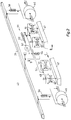
- FIG. 1 shows a cylinder 1 of a rotary printing press with easily bendable, arcuate objects 2, preferably printing plates 2.
- each of the easily bendable, arcuate objects 2, front and rear hook-in edges 3, 4 are arranged at their opposite ends, the respective legs 6, 7 of which enclose an opening angle alpha of less than 90 °.
- These hook-in folds 3, 4 are designed to be dimensionally stable, ie when the objects 2 are clamped on the cylinder 1, these hook-in folds 3, 4 are not bent open.
- This object 2 designed in this way can also consist of printing rubber blankets which are provided with hooked-in folds 3, 4.
- These dimensionally stable hook-in folds 3, 4 of the printing rubber blankets can be folded ends of a metal plate on which the printing rubber blanket has been firmly bonded, for example glued or vulcanized.
- the fabric inserts of the printing rubber blanket can be made of CFRP (carbon fiber reinforced plastic) or GRP (glass fiber reinforced plastic) and the hooked-in folds 3, 4 can be formed therefrom. The following simplifies this described object called pressure plate 2.
- the cylinder 1 of the rotary printing press which is mounted in two side frames 8, 9, is associated with an inking unit protection 11 which is close to the cylinder and is designed as a first printing plate preparation device 12.
- This pressure plate supply device 12 has an upper and a lower, the upper opposite wall 13, 14, which together form a shaft 16.
- the plate cylinder-near end 17 of the upper wall 13 is formed approximately parallel to a tangent 21, which is determined by a cylindrical surface 22 of the cylinder 1 and the hanging bar 19 of the printing plate preparation device 12.
- a second printing plate preparation device 23 can be arranged, the end 24 near the plate cylinder of which is also provided with a hooking strip 26 with a nose-shaped cross section and approximately parallel to that of Cylinder jacket surface 22 of the cylinder 1 and the hanging bar 19 of the first printing plate preparation device 12 fixed tangent 21 is formed.
- a right and left linear drive 27, 28 is fastened in the side frames 8, 9, which consists, for example, of threaded spindles 29, 31 which are rotatably mounted in blocks 32, 33, 34, 36 fixed to the frame.
- other known linear drives 27, 28, such as. B. belt or chain drives, rack and pinion drives, hydraulic or pneumatic servo cylinders or linear motors can be used.
- Via a belt 37, e.g. B. timing belt which mechanically synchronizes the right and left threaded spindles 29, 31, a synchronous rotary movement of the threaded spindles 29, 31 is generated by a drive 38.
- This synchronization can take place mechanically, for example, via chain or cardan shafts or electronically via two separate drives 38 of the linear drives 27, 28.
- the two threaded spindles 29, 31 move a traverse 39 parallel to the axis of rotation 18 of the cylinder 1 in a transport plane 41 which lies above and approximately parallel to the tangent 21 determined by the cylinder surface 22 of the cylinder 1 and the hooking bar 19 of the printing plate preparation device 12.
- threaded nuts 42 are arranged so that the Traverse 39 is operatively connected at right angles to the threaded spindles 29, 31.
- At least one gripping and pressing device 43 is attached along this traverse 39; in the example shown, four gripping and pressing devices 43 are fastened.
- Each individual pressure plate 2 belonging to an axial cylinder section is assigned an independently actuable gripping and pressing device 43.
- an additional linear drive by means of which a single gripping and pressing device 43 executes an axial movement along the crossmember 39, to change a plurality of printing plates 2 arranged along the cylinder 1 with only a single gripping and pressing device 43.
- a gripping and pressing device 43 consists of at least one gripper unit 44 and at least one pressure roller 46.
- This gripper unit 44 and the pressure rollers 46 are independent of the cylinder 1 in the radial direction "D", the gripper unit 44 also in the axial direction "C” displaceable from one another by positioning devices.
- the gripping and pressing device 43 is approximately symmetrical to the center line running in the cylinder circumferential direction Pressure plate 2 set up:
- Each gripping and pressing device 43 is a gripper unit 44 in the form of z.
- two suction strips 47 are formed which are perpendicular to a guide bar 48 against rotation tangential direction "B" of the cylinder 1 and are pressed by compression springs 49 in the direction "B" against a stop 51.
- These guide strips 48 are fastened to a further guide strip 52 and can be displaced in the opposite direction "C” by a positioning drive 53.
- a pneumatic cylinder 54 changes the position of the guide bar 52 with the suction bars 47 along the direction "D".
- a pressure roller 46 which can be placed against the pressure plate 2 against the direction "D” by means of a pneumatic cylinder 56.
- the positioning drive 53 can be designed, for example, as a stepper motor with a threaded spindle. An electric motor with interacting incremental encoders or potentiometers is also possible. Thus, means for detecting its position or the position of the pressure plate 2 preferably cooperate with the positioning drive 53.
- closures 57, 58, 59, 61 arranged in the cylinder 1 in the axial direction, parallel to the axis of rotation 18 of the Cylinder 1 in cylinder pits 62.
- the length of the closures 57, 58, 59, 61 is in each case approximately half the cylinder length.
- These closures 57, 58, 59, 61 are again subdivided into plate width (ie two printing plates 2 are provided for each closure 57, 58, 59, 61) and can be actuated independently both within this subdivision and among themselves.
- the closures 57, 58 are offset from one another by approximately 90 ° in the circumferential direction of the cylinder 1.
- Each closure 57, 58 is assigned a closure 59, 61 opposite each other.
- the cylinder 1 rotates into a clamping position, which is determined by the fact that the center line of the closure 57 is approximately congruent with the solder 81 dropped from the axis of rotation 18 onto the perpendicular 81 to the direction of movement of the linear drives 27, 28.
- the cross member 39 is brought into position by means of the two linear drives 27, 28 for receiving the new pressure plate 84, i. H.
- the suction strips 47 are located in the area of the end 17 of the printing plate supply device 12 near the plate cylinder.
- the gripper unit 44 is displaced in the direction "C".
- the newly applied pressure plate 84 was on the upper wall 13 and on the hanging bar 19 Printing plate supply device 12 placed pre-positioned.
- the suction strips 47 are lowered to the level of the pressure plate 84 by venting the pneumatic cylinder 54 and acted upon by suction air.
- the printing plate 84 is fixed with its printing side to the gripping and pressing device 43.
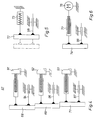
- At least two side register stops 86, 66 are assigned to each of a plurality of pressure plates 84 lying axially next to one another. At least one of these two side register stops 66, 86 can be arranged directly on the hanging bar 19 of the printing plate preparation device 12 or else separately in an area between the printing plate preparation device 12 and the cylinder 1 (FIG. 3).
- a second side register stop 66 is arranged on the hanging bar 19. This side register stop 66 is laterally offset and finely adjustable in the axial direction of the cylinder 1 arranged.
- a side register stop 86 on the cylinder 1 is dispensed with.
- the side register device 67 arranged in the area between the printing plate preparation device 12 and cylinder 1 consists of three successively arranged side register stops 68, 69, 71, which are arranged in a stepped manner in relation to one another in the axial direction of the cylinder 1 (FIG. 4).
- These side register stops 68, 69, 71 are each finely adjustable, for example, by means of a threaded screw 91, 92, 93 and a linear bearing 94, 96, 97.
- only one side register stop 72, 74 is displaceably arranged in a bearing 98, 99, wherein this can be brought into different positions offset from one another in the axial direction of the cylinder 1.
- the side register stop 72 can be attached to a stationary working cylinder 73 (FIG. 5). A piston of this working cylinder 73 moves the side register stop 72 in two positions.
- a side register stop 74 in a continuously adjustable manner in the axial direction of the cylinder 1.
- the side register stop 74 can be positioned, for example, by means of a threaded spindle 77 driven by an electric motor 76 (Fig. 6).
- the pressure plate 84 is axially aligned as follows at the side register stops 66-69, 71, 72, 74: If a plurality of side register stops 66-69, 71, 86 are arranged one behind the other as in the first and second exemplary embodiments, the gripping and pressing device 43 moves with the gripped pressure plate 84 in the direction “B” a preselected one which is assigned to the desired side register stop 66-69, 71, 86 Position.
- the side register stop 72, 74 is adjustable, the side register stop 72, 74 is brought into the preselected position, for example by means of the working cylinder 73 or electric motor 76.
- the gripper unit 44 moves with the gripped pressure plate 88 into a position assigned to the side register stop in the direction "A".
- the positioning drive 53 moves the gripper unit 44 in the axial direction until the pressure plate 84 with its hooked-in bend 3 is pressed against the respective side register stop 66-69, 71, 72, 74, 86.
- the positioning drive 53 is then switched off. This can be done, for example, by limiting the current consumption of an electrically driven positioning drive 53 or it can also be a sensor in the area of the power flow Determination of the contact pressure may be arranged. It is also possible to determine a switch-off criterion from the relationship between the distance traveled and the time required for this by the pressure plate 84 or the positioning drive 53.
- sensors for detecting the position of the pressure plate 84 can also be provided.
- a CCD sensor is suitable for determining the position of the pressure plate 84 and for controlling the position drive 53 of the gripper unit 44.
- This CCD sensor can advantageously be partially covered from the side edge of the pressure plate 84 and fixed in place with respect to the side frame. The CCD sensor is aligned with a specific position of the cylinder 1.
- the starting position of the pressure plate 84 is determined by means of the CCD sensor. Starting from this starting position, the positioning drive 53 is actuated until the pressure plate 84 has reached the desired position with respect to the CCD sensor and thus with respect to the cylinder 1. The positioning drive 53 is now switched off and the pressure plate 84 is transported in the direction of cylinder 1.
- Another embodiment, not shown has two sensors for position detection on the gripping and pressing device 43 and a reference point on the cylinder 1.
- the first sensor which detects a side edge of the pressure plate 84, is fastened to the cross member 39 in the region of a side edge of the pressure plate 84.
- the second sensor which detects the reference point, is arranged to be movable with the gripper unit 44 in the region of the reference point located on the cylinder 1.
- the gripper unit 44 with the second sensor is moved in the axial direction until the reference point of the cylinder 1 is reached. This reference position is stored by the control of the positioning drive 53.
- the control of the positioning drive 53 calculates a distance by which the pressure plate 84 can still be displaced. The positioning drive 53 then performs the necessary axial movement of the pressure plate 84.
- the reference point is on the cylinder 1 as a stop for a side edge of the pressure plate 84 educated.
- the pressure plate 84 suspended in the suspension strip 63 of the cylinder 1 is held with its suspension fold 3 by the gripper device 44 by means of the positioning drive 53 in the axial direction against the stop. If the hooked-in bend 3 abuts the stop, the positioning drive 53 switches off. This shutdown can take place, for example, by means of a current limiter or by evaluating pulse sequences from an incremental encoder.
- the pressure plate 84 is positioned by means of the positioning drive 53 at the preselected position of the cylinder 1 in the axial direction.
- At least one cylinder section has a plurality of selectable target positions lying next to one another.
- Each cylinder section to which a pressure plate is assigned is assigned a plurality of selectable target positions lying next to one another.
- the "rough position" of the plate is thus determined by the selection of the cylinder section.
- the "fine position" is determined by selecting a target position from a plurality of target positions lying next to one another in the axial direction.
Landscapes
- Supply, Installation And Extraction Of Printed Sheets Or Plates (AREA)
- Exposure And Positioning Against Photoresist Photosensitive Materials (AREA)
Applications Claiming Priority (2)
| Application Number | Priority Date | Filing Date | Title |
|---|---|---|---|
| DE19620997 | 1996-05-24 | ||
| DE19620997A DE19620997C2 (de) | 1996-05-24 | 1996-05-24 | Verfahren und Vorrichtung zum axialen Positionieren einer Druckplatte |
Publications (3)
| Publication Number | Publication Date |
|---|---|
| EP0808714A2 true EP0808714A2 (fr) | 1997-11-26 |
| EP0808714A3 EP0808714A3 (fr) | 1998-03-04 |
| EP0808714B1 EP0808714B1 (fr) | 2000-08-16 |
Family
ID=7795247
Family Applications (1)
| Application Number | Title | Priority Date | Filing Date |
|---|---|---|---|
| EP97107854A Expired - Lifetime EP0808714B1 (fr) | 1996-05-24 | 1997-05-14 | Dispositif de positionnement axial d'une plaque d'impression |
Country Status (4)
| Country | Link |
|---|---|
| US (1) | US5806431A (fr) |
| EP (1) | EP0808714B1 (fr) |
| JP (1) | JPH1044374A (fr) |
| DE (2) | DE19620997C2 (fr) |
Cited By (7)
| Publication number | Priority date | Publication date | Assignee | Title |
|---|---|---|---|---|
| EP0933207A1 (fr) * | 1998-01-30 | 1999-08-04 | Heidelberger Druckmaschinen Aktiengesellschaft | Procédé et dispositif pour prépositionnement en parfait repérage d'une plaque à imprimer |
| EP1060884A1 (fr) * | 1999-06-08 | 2000-12-20 | Bieffebi S.p.A. | Dispositif d'accrochage pour plaques d'impression flexographique |
| EP1155838A3 (fr) * | 2000-05-17 | 2004-06-23 | Heidelberger Druckmaschinen Aktiengesellschaft | Cylindre porte-plaque et positionneur extérieur de plaque |
| EP1155837A3 (fr) * | 2000-05-17 | 2004-07-07 | Heidelberger Druckmaschinen Aktiengesellschaft | Machine à imprimer avec un cylindre porte-plaque portant plusieurs plaques |
| WO2005110755A1 (fr) | 2004-05-14 | 2005-11-24 | Koenig & Bauer Aktiengesellschaft | Procede pour acheminer un bloc d'impression jusqu'a un cylindre porte-cliches, procede pour produire ledit bloc d'impression et dispositif pour aligner et guider lateralement un blanchet a acheminer jusqu'a un cylindre de machine a imprimer |
| EP1894722A3 (fr) * | 2006-09-01 | 2011-06-29 | Koenig & Bauer AG | Procédé destiné au montage dýune ou de plusieurs plaques d'impression flexibles sur un cylindre de plaque d'une presse rotative |
| EP2420385A3 (fr) * | 2005-05-09 | 2013-11-27 | Goss Graphic Systems Limited | Chargement semi-automatique de plaques |
Families Citing this family (57)
| Publication number | Priority date | Publication date | Assignee | Title |
|---|---|---|---|---|
| DE10238177B3 (de) | 2002-08-21 | 2004-02-05 | Koenig & Bauer Ag | Vorrichtung zum Andrücken eines Aufzugs an einen Zylinder einer Druckmaschine mit Hilfe von in Umfangsrichtung des Zylinders voneinander beabstandeten ersten und zweiten Wälzelementen |
| DE19516368C2 (de) * | 1995-05-04 | 1999-09-23 | Neumeister Geb Gmbh | Verfahren und Vorrichtung zur Anpassung der Lage von Druckplatten an die Verformung des zu bedruckenden Papieres |
| DE19747478A1 (de) * | 1997-10-28 | 1999-04-29 | Roland Man Druckmasch | Andrückwalze |
| DE19957920A1 (de) | 1998-12-23 | 2000-06-29 | Heidelberger Druckmasch Ag | APW-Induktive Plattenkontrolle |
| DE10039279A1 (de) * | 1999-09-09 | 2001-03-15 | Heidelberger Druckmasch Ag | Walze für Druckmaschinen |
| CZ297967B6 (cs) * | 2000-08-25 | 2007-05-09 | Heidelberger Druckmaschienen Ag | Zarízení na prestavování minimálne jednoho prvku registru v tiskovém stroji a zpusob k provádení takového prestavování |
| US6578484B2 (en) | 2001-06-14 | 2003-06-17 | Masthead International, Inc. | Printing plate lock-up assemblies having jaw assembly and registration pin assembly |
| US6510793B1 (en) * | 2001-06-28 | 2003-01-28 | Eastman Kodak Company | Imaging apparatus and printing plate mounting surface for use in an imaging apparatus having printing plate registration detection |
| CN1323833C (zh) | 2001-10-05 | 2007-07-04 | 柯尼格及包尔公开股份有限公司 | 卷筒纸印刷机 |
| DE50202871D1 (de) | 2001-11-28 | 2005-05-25 | Koenig & Bauer Ag | Vorrichtungen und verfahren zum ausrichten oder montieren eines an einen zylinder einer druckmaschine herangeführten aufzugs |
| DE10158158A1 (de) * | 2001-11-28 | 2003-06-18 | Koenig & Bauer Ag | Vorrichtung zum Aufziehen eines Aufzuges |
| US6772688B2 (en) | 2002-04-05 | 2004-08-10 | Agfa Corporation | Imaging system with automated plate locating mechanism and method for loading printing plate |
| US6729234B2 (en) | 2002-04-05 | 2004-05-04 | Agfa Corporation | Actuation system in an imaging system |
| DE10232026B3 (de) * | 2002-07-16 | 2004-01-08 | Man Roland Druckmaschinen Ag | Vorrichtung zur Einstellung des Seitenregisters für Druckwerke von Rotationsdruckmaschinen |
| DE10236865A1 (de) | 2002-08-12 | 2004-02-26 | Koenig & Bauer Ag | Zylinder in einer Druckeinheit mit mindestens einem Kanal mit mindestens einer Haltevorrichtung |
| JP4181357B2 (ja) * | 2002-08-20 | 2008-11-12 | 株式会社小森コーポレーション | 版挿入装置 |
| DE10314342B3 (de) | 2003-03-28 | 2004-08-26 | Koenig & Bauer Ag | Vorrichtung zum Speichern eines einem Zylinder einer Druckmaschine zuzuführenden Aufzugs und ein Verfahren zum Zuführen eines Aufzugs zu einem Zylinder einer Druckmaschine |
| DE10314343B4 (de) * | 2003-03-28 | 2009-08-13 | Koenig & Bauer Aktiengesellschaft | Vorrichtung zum Speichern eines an einem Zylinder einer Druckmaschine auszutauschenden Aufzugs |
| DE10314341B3 (de) * | 2003-03-28 | 2004-08-12 | Koenig & Bauer Ag | Vorrichtung zum Speichern eines an einem Zylinder einer Druckmaschine auszutauschenden Aufzugs |
| EP1708886B2 (fr) | 2004-01-28 | 2012-04-11 | Koenig & Bauer Aktiengesellschaft | Machine a imprimer faisant appel a un dispositif et a un procede pour compenser un allongement longitudinal et un allongement transversal d'une bande de matiere d' impression imprimee dans differents groupes d'impression |
| DE102004004264C5 (de) | 2004-01-28 | 2011-02-24 | Koenig & Bauer Aktiengesellschaft | Verfahren zur Kompensation einer Querdehnung und/oder einer Längsdehnung eines Bedruckstoffes und Druckmaschine mit mehreren mindestens ein Druckbild auf einem Bedruckstoff erzeugenden Druckwerken |
| DE102004022083B3 (de) * | 2004-05-05 | 2005-10-20 | Roland Man Druckmasch | Vorrichtung zur Durchführung eines Druckplattenwechsels an einem Formzylinder einer Druckmaschine |
| DE102004023434A1 (de) * | 2004-05-10 | 2005-12-08 | Maschinenfabrik Wifag | Rotationsdruckmaschine mit Saugvorrichtung, Saugvorrichtung und Verfahren zum Wechseln einer Druckform |
| DE102004042342B4 (de) | 2004-09-01 | 2008-02-14 | Maschinenfabrik Wifag | Spanneinrichtung für einen Spannkanal eines Zylinderkörpers, Druckformzylinder und Verfahren zur Herstellung |
| DE102004052020B8 (de) * | 2004-10-26 | 2013-07-04 | Wifag Maschinenfabrik Ag | Druckformmanipulator |
| DE102004052021A1 (de) * | 2004-10-26 | 2006-05-04 | Maschinenfabrik Wifag | Druckformmanipulator |
| DE102005042756A1 (de) * | 2005-09-08 | 2007-03-29 | Maschinenfabrik Wifag | Druckformspeicher, Druckwerk mit Druckformspeicher und Verfahren zum Wechseln von Druckformen |
| DE102006054911B3 (de) * | 2006-11-22 | 2008-03-06 | Koenig & Bauer Aktiengesellschaft | Zylinder einer Rotationsdruckmaschine und ein Verfahren zum registerhaltigen Ausrichten eines Aufzugs auf einem Zylinder |
| DE102006059772A1 (de) * | 2006-12-15 | 2008-06-19 | Man Roland Druckmaschinen Ag | Vorrichtung zur Durchführung eines Druckplattenwechsels an einem Formzylinder einer Druckmaschine |
| DE102007035689B3 (de) | 2007-07-30 | 2008-10-16 | Koenig & Bauer Aktiengesellschaft | Verfahren zum Anordnen von Druckformen auf einem Formzylinder einer Druckmaschine |
| DE102008010598A1 (de) * | 2008-02-22 | 2009-08-27 | Manroland Ag | Handhabungsvorrichtung einer Druckmaschine |
| US8800446B2 (en) * | 2008-05-15 | 2014-08-12 | E. I. Du Pont De Nemours And Company | Apparatus and process for positioning a cylindrically-shaped printing element |
| EP2120098B1 (fr) * | 2008-05-15 | 2014-09-24 | E. I. du Pont de Nemours and Company | Appareil et procédé pour positionner un élément d'impression de forme cylindrique |
| DE102010038999B4 (de) | 2010-08-06 | 2014-06-05 | Koenig & Bauer Aktiengesellschaft | Zuführeinrichtung zum Zuführen einer Druckform zu einem Formzylinder einer Druckeinheit |
| DE102010038997A1 (de) | 2010-08-06 | 2012-02-09 | Koenig & Bauer Aktiengesellschaft | Zuführeinrichtung zum Zuführen einer zumindest an ihrem in Produktionsrichtung vorlaufenden Ende einen abgekanteten Einhängeschenkel aufweisenden Druckform zu einem Formzylinder einer Druckeinheit |
| DE102010038998A1 (de) | 2010-08-06 | 2012-02-09 | Koenig & Bauer Aktiengesellschaft | Vorrichtung zum Abführen einer Druckform von einem in einem Gestell einer Druckeinheit angeordneten Formzylinder |
| DE102010042100A1 (de) | 2010-10-07 | 2012-04-12 | Koenig & Bauer Aktiengesellschaft | Transportsystem in einer Druckeinheit für den Transport mindestens einer neu auf einem Formzylinder der Druckeinheit aufzubringenden Druckform sowie Druckeinheit mit einem Transportsystem |
| EP2582523B1 (fr) | 2010-10-07 | 2014-06-11 | Koenig & Bauer Aktiengesellschaft | Unité d'impression d'une machine d'impression avec une unité de stockage et procédé pour la mise à disposition de plusieurs nouvelles formes d'impression destinées a être monté |
| DE102010042111B4 (de) | 2010-10-07 | 2015-03-26 | Koenig & Bauer Aktiengesellschaft | Druckformwechselsystem einer Druckeinheit sowie Logistiksytem einer Druckerei umfassend ein Druckformwechselsystem |
| DE102010042117B4 (de) | 2010-10-07 | 2015-05-28 | Koenig & Bauer Aktiengesellschaft | Druckformwechselsystem einer Druckeinheit sowie Verfahren zum Aufbringen einer oder mehrerer Druckformen auf einem Formzylinder der Druckeinheit |
| WO2012045495A1 (fr) | 2010-10-07 | 2012-04-12 | Koenig & Bauer Aktiengesellschaft | Système de changement de clichés d'une unité d'impression, système logistique dans une imprimerie et procédé permettant d'appliquer un ou plusieurs clichés sur un cylindre porte-clichés d'une unité d'impression |
| WO2012045494A1 (fr) | 2010-10-07 | 2012-04-12 | Koenig & Bauer Aktiengesellschaft | Système de transport et système de changement de clichés dans une unité d'impression, ainsi que système logistique dans une imprimerie |
| DE102010042094B4 (de) | 2010-10-07 | 2015-11-19 | Koenig & Bauer Ag | Trägerelement zur manuellen und/oder automatischen Beförderung mehrerer Druckformen, Transportsystem in einer Druckerei mit einem Trägerelement sowie Verwendung eines Trägerelementes in einem Transportsystem einer Druckerei |
| DE102010042091A1 (de) | 2010-10-07 | 2012-04-12 | Koenig & Bauer Aktiengesellschaft | Speichereinrichtung sowie Verfahren zur Bereitstellung mehrerer neu in einer Druckeinheit auf mindestens einen Formzylinder aufzubringender Druckformen |
| DE102010042114B4 (de) | 2010-10-07 | 2014-11-20 | Koenig & Bauer Aktiengesellschaft | Druckformwechselsystem einer Druckeinheit sowie Logistiksystem einer Druckerei umfassend ein Druckformwechselsystem |
| DE102012202533B3 (de) * | 2012-02-20 | 2013-06-20 | Koenig & Bauer Aktiengesellschaft | Verfahren, Vorrichtung und System zur Bereitstellung eines Satzes von in einer Druckmaschine neu aufzulegender Druckformen |
| US9796173B2 (en) | 2014-07-16 | 2017-10-24 | Kba-Metalpring Gmbh | Device for printing on hollow bodies |
| WO2016008701A1 (fr) | 2014-07-16 | 2016-01-21 | Kba-Metalprint Gmbh | Mécanisme d'encrage d'un groupe d'impression |
| DE102014213811A1 (de) * | 2014-07-16 | 2016-01-21 | Kba-Metalprint Gmbh | Druckwerk mit einem Druckformzylinder |
| PL3169520T3 (pl) | 2014-07-16 | 2018-07-31 | Kba-Metalprint Gmbh | Urządzenie z pewną liczbą zespołów drukujących do zadrukowywania pustych korpusów |
| US9895875B2 (en) | 2014-07-16 | 2018-02-20 | Kba-Metalprint Gmbh | Printing unit having a plate cylinder and plate changer |
| US9833989B2 (en) | 2014-07-16 | 2017-12-05 | Kba-Metalprint Gmbh | Device for printing on hollow bodies |
| EP3271176B1 (fr) * | 2015-03-20 | 2022-05-04 | Bobst Firenze S.r.l. | Dispositif et procédé de montage d'une plaque d'impression sur un support d'impression |
| DE102015219245B3 (de) * | 2015-10-06 | 2016-11-17 | Heidelberger Druckmaschinen Ag | Verfahren zur effizienten Papierdehnungskompensation |
| DE102016000335A1 (de) * | 2016-01-18 | 2017-07-20 | Heidelberger Druckmaschinen Ag | Verfahren zur Kompensation auftrags- und maschinenspezifischer Passerungenauigkeiten und Registerfehler |
| DE102021109488A1 (de) | 2021-04-15 | 2022-10-20 | Koenig & Bauer Ag | Vorrichtung zum Zuführen von Druckplatten und Verfahren zum Durchführen eines Plattenwechsels |
| JP7612205B2 (ja) * | 2021-05-14 | 2025-01-14 | 寿原株式会社 | 刷版交換装置 |
Family Cites Families (12)
| Publication number | Priority date | Publication date | Assignee | Title |
|---|---|---|---|---|
| CH610241A5 (fr) * | 1977-02-07 | 1979-04-12 | Sisenca Sa | |
| DE3136704A1 (de) * | 1981-09-16 | 1983-03-31 | M.A.N.- Roland Druckmaschinen AG, 6050 Offenbach | Vorrichtung zum justieren von auf plattenzylindern montierten druckplatten |
| US4727807A (en) * | 1985-09-30 | 1988-03-01 | Tokyo Kikai Seisakusho | Apparatus for automatically mounting and removing printing plates in rotary printing press |
| DE3545297A1 (de) * | 1985-12-20 | 1987-07-02 | Roland Man Druckmasch | Plattenzylinder mit verstellbarem seitenregister |
| DE4238800A1 (de) * | 1992-11-17 | 1994-05-19 | Shinohara Machinery Co | Verfahren zum Ausrichten von Druckplatten |
| JP3194199B2 (ja) * | 1992-01-17 | 2001-07-30 | 株式会社小森コーポレーション | 版胴への刷版装着装置 |
| JP2573523Y2 (ja) * | 1992-07-31 | 1998-06-04 | 株式会社小森コーポレーション | 印刷機の刷版装着装置 |
| DE4306677C2 (de) * | 1993-03-04 | 1995-01-19 | Heidelberger Druckmasch Ag | Vorrichtung zur Druckvorbereitung mit einer Druckform einer Druckmaschine |
| DE4424903C2 (de) * | 1994-01-17 | 1998-08-27 | Koenig & Bauer Albert Ag | Vorrichtung zur Montage, Demontage und Transport von leicht biegbaren, bogenförmigen Gegenständen mit Einhängeabkantungen |
| JP2691974B2 (ja) * | 1994-11-16 | 1997-12-17 | 株式会社東京機械製作所 | 刷版支持装置及び刷版着脱装置 |
| DE19531024B4 (de) * | 1994-11-16 | 2005-01-27 | Kabushiki Kaisha Tokyo Kikai Seisakusho | Vorrichtung und Verfahren zum Anbringen einer Druckplatte auf einem Plattenzylinder einer Rotationsdruckpresse |
| DE4442574C2 (de) * | 1994-11-30 | 1996-11-28 | Koenig & Bauer Albert Ag | Verfahren und Vorrichtung zur Bereitstellung einer Druckplatte |
-
1996
- 1996-05-24 DE DE19620997A patent/DE19620997C2/de not_active Expired - Fee Related
-
1997
- 1997-05-14 EP EP97107854A patent/EP0808714B1/fr not_active Expired - Lifetime
- 1997-05-14 DE DE59702179T patent/DE59702179D1/de not_active Expired - Fee Related
- 1997-05-20 JP JP9129186A patent/JPH1044374A/ja active Pending
- 1997-05-23 US US08/862,385 patent/US5806431A/en not_active Expired - Fee Related
Cited By (9)
| Publication number | Priority date | Publication date | Assignee | Title |
|---|---|---|---|---|
| EP0933207A1 (fr) * | 1998-01-30 | 1999-08-04 | Heidelberger Druckmaschinen Aktiengesellschaft | Procédé et dispositif pour prépositionnement en parfait repérage d'une plaque à imprimer |
| US6571708B1 (en) | 1998-01-30 | 2003-06-03 | Heidelberger Druckmaschinen Ag | Method and device for in-register pre-positioning a printing plate |
| EP1060884A1 (fr) * | 1999-06-08 | 2000-12-20 | Bieffebi S.p.A. | Dispositif d'accrochage pour plaques d'impression flexographique |
| EP1155838A3 (fr) * | 2000-05-17 | 2004-06-23 | Heidelberger Druckmaschinen Aktiengesellschaft | Cylindre porte-plaque et positionneur extérieur de plaque |
| EP1155837A3 (fr) * | 2000-05-17 | 2004-07-07 | Heidelberger Druckmaschinen Aktiengesellschaft | Machine à imprimer avec un cylindre porte-plaque portant plusieurs plaques |
| WO2005110755A1 (fr) | 2004-05-14 | 2005-11-24 | Koenig & Bauer Aktiengesellschaft | Procede pour acheminer un bloc d'impression jusqu'a un cylindre porte-cliches, procede pour produire ledit bloc d'impression et dispositif pour aligner et guider lateralement un blanchet a acheminer jusqu'a un cylindre de machine a imprimer |
| US7647868B2 (en) | 2004-05-14 | 2010-01-19 | Koenig & Bauer Aktiengesellschaft | Method for feeding a printing forme to a forme cylinder of a printing press |
| EP2420385A3 (fr) * | 2005-05-09 | 2013-11-27 | Goss Graphic Systems Limited | Chargement semi-automatique de plaques |
| EP1894722A3 (fr) * | 2006-09-01 | 2011-06-29 | Koenig & Bauer AG | Procédé destiné au montage dýune ou de plusieurs plaques d'impression flexibles sur un cylindre de plaque d'une presse rotative |
Also Published As
| Publication number | Publication date |
|---|---|
| JPH1044374A (ja) | 1998-02-17 |
| DE59702179D1 (de) | 2000-09-21 |
| EP0808714A3 (fr) | 1998-03-04 |
| EP0808714B1 (fr) | 2000-08-16 |
| US5806431A (en) | 1998-09-15 |
| DE19620997A1 (de) | 1997-11-27 |
| DE19620997C2 (de) | 1998-03-26 |
Similar Documents
| Publication | Publication Date | Title |
|---|---|---|
| DE19620997C2 (de) | Verfahren und Vorrichtung zum axialen Positionieren einer Druckplatte | |
| EP0570702B2 (fr) | Dispositif pour alimenter des plaques d'impression vers le cylindre porte-plaque d'une machine à imprimer, en particulier machine à imprimer offset des feuilles | |
| DE2642381C3 (de) | Einrichtung zum registerhaltigen Zuführen einer Bahn | |
| EP0740608B1 (fr) | Dispositif de montage, de demontage et de transport d'objets courbes faciles a plier et pourvus de rebords de suspension | |
| EP0654349A1 (fr) | Magasin pour l'échange automatique de plaques d'impression dans une machine à imprimer | |
| DE10052015A1 (de) | Bewegbarer Falzapparat und Falztrichteranordnung | |
| DE4409693C1 (de) | Vorrichtung zum Einziehen von Bedruckstoffbahnen über Wendestangen | |
| DE4424931C2 (de) | Vorrichtung zur Montage, Demontage und Transport von leicht biegbaren, bogenförmigen Gegenständen mit Einhängeabkantungen | |
| EP0740607B1 (fr) | Dispositif pour le montage, le demontage et le transport d'objets courbes facilement pliables pourvus d'aretes d'accrochage | |
| DE4035035C2 (de) | Einrichtung zur axialen Einstellung von Saugringen in Auslagen von Druckmaschinen | |
| EP0426022A2 (fr) | Cylindre de plaque dans une machine d'impression | |
| WO2008064960A1 (fr) | Procédé d'exploitation d'une unité d'impression dotée d'au moins un mécanisme d'impression et mécanisme d'impression destiné à la mise en œuvre du procédé | |
| EP1070583B1 (fr) | Méthode et dispositif pour le changement de plaques. | |
| DE19508254B4 (de) | Verfahren zum Transportieren von einzelnen Bogen | |
| DE4035036C2 (de) | Einrichtung zur axialen Einstellung von Saugringen in Bogenbremsen von Druckmaschinen | |
| EP0835754A2 (fr) | Réglage décentralisé individuel des surfaces d'appui des pinces dans les cylindres de transport de feuilles des presses rotatives | |
| EP1535734B1 (fr) | Procédé pour presser un recouvrement sur un cylindre d'une machine à imprimer avec des éléments de pression | |
| EP0553739B1 (fr) | Dispositif pour régler les éléments de guidage de feuilles d'une rotative | |
| DE10349896B4 (de) | Bogendruckmaschine und Verfahren zum Betreiben einer Bogendruckmaschine | |
| EP0726146B1 (fr) | Dispositif de commande pour une machine à imprimer | |
| DE3246938A1 (de) | Druckmaschine mir druckplattenzylinder, farbauftragwalze und gegendruckzylinder | |
| DE4242606A1 (fr) | ||
| DE19538322C2 (de) | Einrichtung zur axialen Verstellung von Leitelementen | |
| DD258400A1 (de) | Leiteinrichtung fuer biegesteife materialien | |
| DE3531145C2 (fr) |
Legal Events
| Date | Code | Title | Description |
|---|---|---|---|
| PUAI | Public reference made under article 153(3) epc to a published international application that has entered the european phase |
Free format text: ORIGINAL CODE: 0009012 |
|
| AK | Designated contracting states |
Kind code of ref document: A2 Designated state(s): CH DE FR GB IT LI SE |
|
| PUAL | Search report despatched |
Free format text: ORIGINAL CODE: 0009013 |
|
| AK | Designated contracting states |
Kind code of ref document: A3 Designated state(s): CH DE FR GB IT LI SE |
|
| 17P | Request for examination filed |
Effective date: 19980826 |
|
| RAP1 | Party data changed (applicant data changed or rights of an application transferred) |
Owner name: KOENIG & BAUER AKTIENGESELLSCHAFT |
|
| 17Q | First examination report despatched |
Effective date: 19990218 |
|
| GRAG | Despatch of communication of intention to grant |
Free format text: ORIGINAL CODE: EPIDOS AGRA |
|
| RTI1 | Title (correction) |
Free format text: APPARATUS FOR AXIALLY POSITIONING OF A PRINTING PLATE |
|
| GRAG | Despatch of communication of intention to grant |
Free format text: ORIGINAL CODE: EPIDOS AGRA |
|
| GRAH | Despatch of communication of intention to grant a patent |
Free format text: ORIGINAL CODE: EPIDOS IGRA |
|
| GRAH | Despatch of communication of intention to grant a patent |
Free format text: ORIGINAL CODE: EPIDOS IGRA |
|
| GRAA | (expected) grant |
Free format text: ORIGINAL CODE: 0009210 |
|
| AK | Designated contracting states |
Kind code of ref document: B1 Designated state(s): CH DE FR GB IT LI SE |
|
| REG | Reference to a national code |
Ref country code: CH Ref legal event code: EP |
|
| ITF | It: translation for a ep patent filed | ||
| GBT | Gb: translation of ep patent filed (gb section 77(6)(a)/1977) |
Effective date: 20000816 |
|
| REF | Corresponds to: |
Ref document number: 59702179 Country of ref document: DE Date of ref document: 20000921 |
|
| ET | Fr: translation filed | ||
| PGFP | Annual fee paid to national office [announced via postgrant information from national office to epo] |
Ref country code: GB Payment date: 20010425 Year of fee payment: 5 |
|
| PGFP | Annual fee paid to national office [announced via postgrant information from national office to epo] |
Ref country code: FR Payment date: 20010518 Year of fee payment: 5 |
|
| PGFP | Annual fee paid to national office [announced via postgrant information from national office to epo] |
Ref country code: SE Payment date: 20010521 Year of fee payment: 5 |
|
| PGFP | Annual fee paid to national office [announced via postgrant information from national office to epo] |
Ref country code: CH Payment date: 20010607 Year of fee payment: 5 |
|
| PLBE | No opposition filed within time limit |
Free format text: ORIGINAL CODE: 0009261 |
|
| STAA | Information on the status of an ep patent application or granted ep patent |
Free format text: STATUS: NO OPPOSITION FILED WITHIN TIME LIMIT |
|
| 26N | No opposition filed | ||
| REG | Reference to a national code |
Ref country code: GB Ref legal event code: IF02 |
|
| PG25 | Lapsed in a contracting state [announced via postgrant information from national office to epo] |
Ref country code: GB Free format text: LAPSE BECAUSE OF NON-PAYMENT OF DUE FEES Effective date: 20020514 |
|
| PG25 | Lapsed in a contracting state [announced via postgrant information from national office to epo] |
Ref country code: SE Free format text: LAPSE BECAUSE OF NON-PAYMENT OF DUE FEES Effective date: 20020515 |
|
| PG25 | Lapsed in a contracting state [announced via postgrant information from national office to epo] |
Ref country code: LI Free format text: LAPSE BECAUSE OF NON-PAYMENT OF DUE FEES Effective date: 20020531 Ref country code: CH Free format text: LAPSE BECAUSE OF NON-PAYMENT OF DUE FEES Effective date: 20020531 |
|
| GBPC | Gb: european patent ceased through non-payment of renewal fee |
Effective date: 20020514 |
|
| EUG | Se: european patent has lapsed | ||
| REG | Reference to a national code |
Ref country code: CH Ref legal event code: PL |
|
| PG25 | Lapsed in a contracting state [announced via postgrant information from national office to epo] |
Ref country code: FR Free format text: LAPSE BECAUSE OF NON-PAYMENT OF DUE FEES Effective date: 20030131 |
|
| REG | Reference to a national code |
Ref country code: FR Ref legal event code: ST |
|
| PG25 | Lapsed in a contracting state [announced via postgrant information from national office to epo] |
Ref country code: IT Free format text: LAPSE BECAUSE OF NON-PAYMENT OF DUE FEES;WARNING: LAPSES OF ITALIAN PATENTS WITH EFFECTIVE DATE BEFORE 2007 MAY HAVE OCCURRED AT ANY TIME BEFORE 2007. THE CORRECT EFFECTIVE DATE MAY BE DIFFERENT FROM THE ONE RECORDED. Effective date: 20050514 |
|
| PGFP | Annual fee paid to national office [announced via postgrant information from national office to epo] |
Ref country code: DE Payment date: 20080929 Year of fee payment: 12 |
|
| PG25 | Lapsed in a contracting state [announced via postgrant information from national office to epo] |
Ref country code: DE Free format text: LAPSE BECAUSE OF NON-PAYMENT OF DUE FEES Effective date: 20091201 |