EP0928369B1 - Moteur a allumage par compression d'une charge premelangee avec regulation optimale de la combustion - Google Patents
Moteur a allumage par compression d'une charge premelangee avec regulation optimale de la combustion Download PDFInfo
- Publication number
- EP0928369B1 EP0928369B1 EP97939509A EP97939509A EP0928369B1 EP 0928369 B1 EP0928369 B1 EP 0928369B1 EP 97939509 A EP97939509 A EP 97939509A EP 97939509 A EP97939509 A EP 97939509A EP 0928369 B1 EP0928369 B1 EP 0928369B1
- Authority
- EP
- European Patent Office
- Prior art keywords
- combustion
- engine
- control means
- fuel
- combustion chamber
- Prior art date
- Legal status (The legal status is an assumption and is not a legal conclusion. Google has not performed a legal analysis and makes no representation as to the accuracy of the status listed.)
- Expired - Lifetime
Links
Images


Classifications
-
- F—MECHANICAL ENGINEERING; LIGHTING; HEATING; WEAPONS; BLASTING
- F02—COMBUSTION ENGINES; HOT-GAS OR COMBUSTION-PRODUCT ENGINE PLANTS
- F02D—CONTROLLING COMBUSTION ENGINES
- F02D41/00—Electrical control of supply of combustible mixture or its constituents
- F02D41/30—Controlling fuel injection
- F02D41/3011—Controlling fuel injection according to or using specific or several modes of combustion
- F02D41/3017—Controlling fuel injection according to or using specific or several modes of combustion characterised by the mode(s) being used
- F02D41/3023—Controlling fuel injection according to or using specific or several modes of combustion characterised by the mode(s) being used a mode being the stratified charge spark-ignited mode
- F02D41/3029—Controlling fuel injection according to or using specific or several modes of combustion characterised by the mode(s) being used a mode being the stratified charge spark-ignited mode further comprising a homogeneous charge spark-ignited mode
-
- F—MECHANICAL ENGINEERING; LIGHTING; HEATING; WEAPONS; BLASTING
- F02—COMBUSTION ENGINES; HOT-GAS OR COMBUSTION-PRODUCT ENGINE PLANTS
- F02B—INTERNAL-COMBUSTION PISTON ENGINES; COMBUSTION ENGINES IN GENERAL
- F02B1/00—Engines characterised by fuel-air mixture compression
- F02B1/12—Engines characterised by fuel-air mixture compression with compression ignition
-
- F—MECHANICAL ENGINEERING; LIGHTING; HEATING; WEAPONS; BLASTING
- F02—COMBUSTION ENGINES; HOT-GAS OR COMBUSTION-PRODUCT ENGINE PLANTS
- F02B—INTERNAL-COMBUSTION PISTON ENGINES; COMBUSTION ENGINES IN GENERAL
- F02B19/00—Engines characterised by precombustion chambers
- F02B19/14—Engines characterised by precombustion chambers with compression ignition
-
- F—MECHANICAL ENGINEERING; LIGHTING; HEATING; WEAPONS; BLASTING
- F02—COMBUSTION ENGINES; HOT-GAS OR COMBUSTION-PRODUCT ENGINE PLANTS
- F02D—CONTROLLING COMBUSTION ENGINES
- F02D13/00—Controlling the engine output power by varying inlet or exhaust valve operating characteristics, e.g. timing
- F02D13/02—Controlling the engine output power by varying inlet or exhaust valve operating characteristics, e.g. timing during engine operation
- F02D13/0203—Variable control of intake and exhaust valves
- F02D13/0215—Variable control of intake and exhaust valves changing the valve timing only
-
- F—MECHANICAL ENGINEERING; LIGHTING; HEATING; WEAPONS; BLASTING
- F02—COMBUSTION ENGINES; HOT-GAS OR COMBUSTION-PRODUCT ENGINE PLANTS
- F02D—CONTROLLING COMBUSTION ENGINES
- F02D13/00—Controlling the engine output power by varying inlet or exhaust valve operating characteristics, e.g. timing
- F02D13/02—Controlling the engine output power by varying inlet or exhaust valve operating characteristics, e.g. timing during engine operation
- F02D13/0261—Controlling the valve overlap
-
- F—MECHANICAL ENGINEERING; LIGHTING; HEATING; WEAPONS; BLASTING
- F02—COMBUSTION ENGINES; HOT-GAS OR COMBUSTION-PRODUCT ENGINE PLANTS
- F02D—CONTROLLING COMBUSTION ENGINES
- F02D13/00—Controlling the engine output power by varying inlet or exhaust valve operating characteristics, e.g. timing
- F02D13/02—Controlling the engine output power by varying inlet or exhaust valve operating characteristics, e.g. timing during engine operation
- F02D13/0269—Controlling the valves to perform a Miller-Atkinson cycle
-
- F—MECHANICAL ENGINEERING; LIGHTING; HEATING; WEAPONS; BLASTING
- F02—COMBUSTION ENGINES; HOT-GAS OR COMBUSTION-PRODUCT ENGINE PLANTS
- F02D—CONTROLLING COMBUSTION ENGINES
- F02D15/00—Varying compression ratio
- F02D15/04—Varying compression ratio by alteration of volume of compression space without changing piston stroke
-
- F—MECHANICAL ENGINEERING; LIGHTING; HEATING; WEAPONS; BLASTING
- F02—COMBUSTION ENGINES; HOT-GAS OR COMBUSTION-PRODUCT ENGINE PLANTS
- F02D—CONTROLLING COMBUSTION ENGINES
- F02D19/00—Controlling engines characterised by their use of non-liquid fuels, pluralities of fuels, or non-fuel substances added to the combustible mixtures
- F02D19/06—Controlling engines characterised by their use of non-liquid fuels, pluralities of fuels, or non-fuel substances added to the combustible mixtures peculiar to engines working with pluralities of fuels, e.g. alternatively with light and heavy fuel oil, other than engines indifferent to the fuel consumed
- F02D19/0639—Controlling engines characterised by their use of non-liquid fuels, pluralities of fuels, or non-fuel substances added to the combustible mixtures peculiar to engines working with pluralities of fuels, e.g. alternatively with light and heavy fuel oil, other than engines indifferent to the fuel consumed characterised by the type of fuels
- F02D19/0649—Liquid fuels having different boiling temperatures, volatilities, densities, viscosities, cetane or octane numbers
-
- F—MECHANICAL ENGINEERING; LIGHTING; HEATING; WEAPONS; BLASTING
- F02—COMBUSTION ENGINES; HOT-GAS OR COMBUSTION-PRODUCT ENGINE PLANTS
- F02D—CONTROLLING COMBUSTION ENGINES
- F02D35/00—Controlling engines, dependent on conditions exterior or interior to engines, not otherwise provided for
- F02D35/02—Controlling engines, dependent on conditions exterior or interior to engines, not otherwise provided for on interior conditions
- F02D35/023—Controlling engines, dependent on conditions exterior or interior to engines, not otherwise provided for on interior conditions by determining the cylinder pressure
-
- F—MECHANICAL ENGINEERING; LIGHTING; HEATING; WEAPONS; BLASTING
- F02—COMBUSTION ENGINES; HOT-GAS OR COMBUSTION-PRODUCT ENGINE PLANTS
- F02D—CONTROLLING COMBUSTION ENGINES
- F02D41/00—Electrical control of supply of combustible mixture or its constituents
- F02D41/0025—Controlling engines characterised by use of non-liquid fuels, pluralities of fuels, or non-fuel substances added to the combustible mixtures
-
- F—MECHANICAL ENGINEERING; LIGHTING; HEATING; WEAPONS; BLASTING
- F02—COMBUSTION ENGINES; HOT-GAS OR COMBUSTION-PRODUCT ENGINE PLANTS
- F02D—CONTROLLING COMBUSTION ENGINES
- F02D41/00—Electrical control of supply of combustible mixture or its constituents
- F02D41/30—Controlling fuel injection
- F02D41/3011—Controlling fuel injection according to or using specific or several modes of combustion
- F02D41/3017—Controlling fuel injection according to or using specific or several modes of combustion characterised by the mode(s) being used
- F02D41/3035—Controlling fuel injection according to or using specific or several modes of combustion characterised by the mode(s) being used a mode being the premixed charge compression-ignition mode
- F02D41/3041—Controlling fuel injection according to or using specific or several modes of combustion characterised by the mode(s) being used a mode being the premixed charge compression-ignition mode with means for triggering compression ignition, e.g. spark plug
-
- F—MECHANICAL ENGINEERING; LIGHTING; HEATING; WEAPONS; BLASTING
- F02—COMBUSTION ENGINES; HOT-GAS OR COMBUSTION-PRODUCT ENGINE PLANTS
- F02D—CONTROLLING COMBUSTION ENGINES
- F02D41/00—Electrical control of supply of combustible mixture or its constituents
- F02D41/30—Controlling fuel injection
- F02D41/38—Controlling fuel injection of the high pressure type
-
- F—MECHANICAL ENGINEERING; LIGHTING; HEATING; WEAPONS; BLASTING
- F02—COMBUSTION ENGINES; HOT-GAS OR COMBUSTION-PRODUCT ENGINE PLANTS
- F02M—SUPPLYING COMBUSTION ENGINES IN GENERAL WITH COMBUSTIBLE MIXTURES OR CONSTITUENTS THEREOF
- F02M26/00—Engine-pertinent apparatus for adding exhaust gases to combustion-air, main fuel or fuel-air mixture, e.g. by exhaust gas recirculation [EGR] systems
- F02M26/01—Internal exhaust gas recirculation, i.e. wherein the residual exhaust gases are trapped in the cylinder or pushed back from the intake or the exhaust manifold into the combustion chamber without the use of additional passages
-
- F—MECHANICAL ENGINEERING; LIGHTING; HEATING; WEAPONS; BLASTING
- F02—COMBUSTION ENGINES; HOT-GAS OR COMBUSTION-PRODUCT ENGINE PLANTS
- F02M—SUPPLYING COMBUSTION ENGINES IN GENERAL WITH COMBUSTIBLE MIXTURES OR CONSTITUENTS THEREOF
- F02M26/00—Engine-pertinent apparatus for adding exhaust gases to combustion-air, main fuel or fuel-air mixture, e.g. by exhaust gas recirculation [EGR] systems
- F02M26/13—Arrangement or layout of EGR passages, e.g. in relation to specific engine parts or for incorporation of accessories
- F02M26/22—Arrangement or layout of EGR passages, e.g. in relation to specific engine parts or for incorporation of accessories with coolers in the recirculation passage
- F02M26/23—Layout, e.g. schematics
- F02M26/28—Layout, e.g. schematics with liquid-cooled heat exchangers
-
- F—MECHANICAL ENGINEERING; LIGHTING; HEATING; WEAPONS; BLASTING
- F02—COMBUSTION ENGINES; HOT-GAS OR COMBUSTION-PRODUCT ENGINE PLANTS
- F02M—SUPPLYING COMBUSTION ENGINES IN GENERAL WITH COMBUSTIBLE MIXTURES OR CONSTITUENTS THEREOF
- F02M26/00—Engine-pertinent apparatus for adding exhaust gases to combustion-air, main fuel or fuel-air mixture, e.g. by exhaust gas recirculation [EGR] systems
- F02M26/13—Arrangement or layout of EGR passages, e.g. in relation to specific engine parts or for incorporation of accessories
- F02M26/22—Arrangement or layout of EGR passages, e.g. in relation to specific engine parts or for incorporation of accessories with coolers in the recirculation passage
- F02M26/33—Arrangement or layout of EGR passages, e.g. in relation to specific engine parts or for incorporation of accessories with coolers in the recirculation passage controlling the temperature of the recirculated gases
-
- F—MECHANICAL ENGINEERING; LIGHTING; HEATING; WEAPONS; BLASTING
- F02—COMBUSTION ENGINES; HOT-GAS OR COMBUSTION-PRODUCT ENGINE PLANTS
- F02M—SUPPLYING COMBUSTION ENGINES IN GENERAL WITH COMBUSTIBLE MIXTURES OR CONSTITUENTS THEREOF
- F02M26/00—Engine-pertinent apparatus for adding exhaust gases to combustion-air, main fuel or fuel-air mixture, e.g. by exhaust gas recirculation [EGR] systems
- F02M26/13—Arrangement or layout of EGR passages, e.g. in relation to specific engine parts or for incorporation of accessories
- F02M26/42—Arrangement or layout of EGR passages, e.g. in relation to specific engine parts or for incorporation of accessories having two or more EGR passages; EGR systems specially adapted for engines having two or more cylinders
- F02M26/43—Arrangement or layout of EGR passages, e.g. in relation to specific engine parts or for incorporation of accessories having two or more EGR passages; EGR systems specially adapted for engines having two or more cylinders in which exhaust from only one cylinder or only a group of cylinders is directed to the intake of the engine
-
- F—MECHANICAL ENGINEERING; LIGHTING; HEATING; WEAPONS; BLASTING
- F02—COMBUSTION ENGINES; HOT-GAS OR COMBUSTION-PRODUCT ENGINE PLANTS
- F02M—SUPPLYING COMBUSTION ENGINES IN GENERAL WITH COMBUSTIBLE MIXTURES OR CONSTITUENTS THEREOF
- F02M31/00—Apparatus for thermally treating combustion-air, fuel, or fuel-air mixture
- F02M31/02—Apparatus for thermally treating combustion-air, fuel, or fuel-air mixture for heating
-
- F—MECHANICAL ENGINEERING; LIGHTING; HEATING; WEAPONS; BLASTING
- F02—COMBUSTION ENGINES; HOT-GAS OR COMBUSTION-PRODUCT ENGINE PLANTS
- F02M—SUPPLYING COMBUSTION ENGINES IN GENERAL WITH COMBUSTIBLE MIXTURES OR CONSTITUENTS THEREOF
- F02M31/00—Apparatus for thermally treating combustion-air, fuel, or fuel-air mixture
- F02M31/20—Apparatus for thermally treating combustion-air, fuel, or fuel-air mixture for cooling
-
- F—MECHANICAL ENGINEERING; LIGHTING; HEATING; WEAPONS; BLASTING
- F02—COMBUSTION ENGINES; HOT-GAS OR COMBUSTION-PRODUCT ENGINE PLANTS
- F02P—IGNITION, OTHER THAN COMPRESSION IGNITION, FOR INTERNAL-COMBUSTION ENGINES; TESTING OF IGNITION TIMING IN COMPRESSION-IGNITION ENGINES
- F02P19/00—Incandescent ignition, e.g. during starting of internal combustion engines; Combination of incandescent and spark ignition
-
- F—MECHANICAL ENGINEERING; LIGHTING; HEATING; WEAPONS; BLASTING
- F02—COMBUSTION ENGINES; HOT-GAS OR COMBUSTION-PRODUCT ENGINE PLANTS
- F02B—INTERNAL-COMBUSTION PISTON ENGINES; COMBUSTION ENGINES IN GENERAL
- F02B75/00—Other engines
- F02B75/02—Engines characterised by their cycles, e.g. six-stroke
- F02B2075/022—Engines characterised by their cycles, e.g. six-stroke having less than six strokes per cycle
- F02B2075/025—Engines characterised by their cycles, e.g. six-stroke having less than six strokes per cycle two
-
- F—MECHANICAL ENGINEERING; LIGHTING; HEATING; WEAPONS; BLASTING
- F02—COMBUSTION ENGINES; HOT-GAS OR COMBUSTION-PRODUCT ENGINE PLANTS
- F02B—INTERNAL-COMBUSTION PISTON ENGINES; COMBUSTION ENGINES IN GENERAL
- F02B2275/00—Other engines, components or details, not provided for in other groups of this subclass
- F02B2275/32—Miller cycle
-
- F—MECHANICAL ENGINEERING; LIGHTING; HEATING; WEAPONS; BLASTING
- F02—COMBUSTION ENGINES; HOT-GAS OR COMBUSTION-PRODUCT ENGINE PLANTS
- F02B—INTERNAL-COMBUSTION PISTON ENGINES; COMBUSTION ENGINES IN GENERAL
- F02B3/00—Engines characterised by air compression and subsequent fuel addition
- F02B3/06—Engines characterised by air compression and subsequent fuel addition with compression ignition
-
- F—MECHANICAL ENGINEERING; LIGHTING; HEATING; WEAPONS; BLASTING
- F02—COMBUSTION ENGINES; HOT-GAS OR COMBUSTION-PRODUCT ENGINE PLANTS
- F02D—CONTROLLING COMBUSTION ENGINES
- F02D13/00—Controlling the engine output power by varying inlet or exhaust valve operating characteristics, e.g. timing
- F02D13/02—Controlling the engine output power by varying inlet or exhaust valve operating characteristics, e.g. timing during engine operation
- F02D2013/0292—Controlling the engine output power by varying inlet or exhaust valve operating characteristics, e.g. timing during engine operation in the start-up phase, e.g. for warming-up cold engine or catalyst
-
- F—MECHANICAL ENGINEERING; LIGHTING; HEATING; WEAPONS; BLASTING
- F02—COMBUSTION ENGINES; HOT-GAS OR COMBUSTION-PRODUCT ENGINE PLANTS
- F02M—SUPPLYING COMBUSTION ENGINES IN GENERAL WITH COMBUSTIBLE MIXTURES OR CONSTITUENTS THEREOF
- F02M26/00—Engine-pertinent apparatus for adding exhaust gases to combustion-air, main fuel or fuel-air mixture, e.g. by exhaust gas recirculation [EGR] systems
- F02M26/02—EGR systems specially adapted for supercharged engines
- F02M26/04—EGR systems specially adapted for supercharged engines with a single turbocharger
- F02M26/07—Mixed pressure loops, i.e. wherein recirculated exhaust gas is either taken out upstream of the turbine and reintroduced upstream of the compressor, or is taken out downstream of the turbine and reintroduced downstream of the compressor
-
- F—MECHANICAL ENGINEERING; LIGHTING; HEATING; WEAPONS; BLASTING
- F02—COMBUSTION ENGINES; HOT-GAS OR COMBUSTION-PRODUCT ENGINE PLANTS
- F02M—SUPPLYING COMBUSTION ENGINES IN GENERAL WITH COMBUSTIBLE MIXTURES OR CONSTITUENTS THEREOF
- F02M26/00—Engine-pertinent apparatus for adding exhaust gases to combustion-air, main fuel or fuel-air mixture, e.g. by exhaust gas recirculation [EGR] systems
- F02M26/02—EGR systems specially adapted for supercharged engines
- F02M26/08—EGR systems specially adapted for supercharged engines for engines having two or more intake charge compressors or exhaust gas turbines, e.g. a turbocharger combined with an additional compressor
-
- F—MECHANICAL ENGINEERING; LIGHTING; HEATING; WEAPONS; BLASTING
- F02—COMBUSTION ENGINES; HOT-GAS OR COMBUSTION-PRODUCT ENGINE PLANTS
- F02M—SUPPLYING COMBUSTION ENGINES IN GENERAL WITH COMBUSTIBLE MIXTURES OR CONSTITUENTS THEREOF
- F02M26/00—Engine-pertinent apparatus for adding exhaust gases to combustion-air, main fuel or fuel-air mixture, e.g. by exhaust gas recirculation [EGR] systems
- F02M26/13—Arrangement or layout of EGR passages, e.g. in relation to specific engine parts or for incorporation of accessories
- F02M26/22—Arrangement or layout of EGR passages, e.g. in relation to specific engine parts or for incorporation of accessories with coolers in the recirculation passage
- F02M26/23—Layout, e.g. schematics
-
- Y—GENERAL TAGGING OF NEW TECHNOLOGICAL DEVELOPMENTS; GENERAL TAGGING OF CROSS-SECTIONAL TECHNOLOGIES SPANNING OVER SEVERAL SECTIONS OF THE IPC; TECHNICAL SUBJECTS COVERED BY FORMER USPC CROSS-REFERENCE ART COLLECTIONS [XRACs] AND DIGESTS
- Y02—TECHNOLOGIES OR APPLICATIONS FOR MITIGATION OR ADAPTATION AGAINST CLIMATE CHANGE
- Y02T—CLIMATE CHANGE MITIGATION TECHNOLOGIES RELATED TO TRANSPORTATION
- Y02T10/00—Road transport of goods or passengers
- Y02T10/10—Internal combustion engine [ICE] based vehicles
- Y02T10/12—Improving ICE efficiencies
-
- Y—GENERAL TAGGING OF NEW TECHNOLOGICAL DEVELOPMENTS; GENERAL TAGGING OF CROSS-SECTIONAL TECHNOLOGIES SPANNING OVER SEVERAL SECTIONS OF THE IPC; TECHNICAL SUBJECTS COVERED BY FORMER USPC CROSS-REFERENCE ART COLLECTIONS [XRACs] AND DIGESTS
- Y02—TECHNOLOGIES OR APPLICATIONS FOR MITIGATION OR ADAPTATION AGAINST CLIMATE CHANGE
- Y02T—CLIMATE CHANGE MITIGATION TECHNOLOGIES RELATED TO TRANSPORTATION
- Y02T10/00—Road transport of goods or passengers
- Y02T10/10—Internal combustion engine [ICE] based vehicles
- Y02T10/30—Use of alternative fuels, e.g. biofuels
-
- Y—GENERAL TAGGING OF NEW TECHNOLOGICAL DEVELOPMENTS; GENERAL TAGGING OF CROSS-SECTIONAL TECHNOLOGIES SPANNING OVER SEVERAL SECTIONS OF THE IPC; TECHNICAL SUBJECTS COVERED BY FORMER USPC CROSS-REFERENCE ART COLLECTIONS [XRACs] AND DIGESTS
- Y02—TECHNOLOGIES OR APPLICATIONS FOR MITIGATION OR ADAPTATION AGAINST CLIMATE CHANGE
- Y02T—CLIMATE CHANGE MITIGATION TECHNOLOGIES RELATED TO TRANSPORTATION
- Y02T10/00—Road transport of goods or passengers
- Y02T10/10—Internal combustion engine [ICE] based vehicles
- Y02T10/40—Engine management systems
Definitions
- This invention relates to an internal combustion engine operable in a premixed charge compression ignition mode and to a method of operating such a premixed charge compression ignition internal combustion engine.
- Diesel and spark ignited engines effectively control the start of combustion (SOC) using simple, yet distinct means.
- the diesel engine controls the SOC by the timing of fuel injection.
- spark ignited engine the SOC is controlled by the spark timing.
- the major advantage that a spark-ignited natural gas, or gasoline, engine has over a diesel engine is the ability to achieve extremely low NOx and particulate emissions levels.
- diesel engines have over premixed charge spark ignited engines is higher thermal efficiency.
- One key reason for the higher efficiency of diesel engines is the ability to use higher compression ratios than premixed charge spark ignited engines (the compression ratio in premixed charge spark ignited engines has to be kept relatively low to avoid knock).
- a second key reason for the higher efficiency of diesel engines lies in the ability to control the diesel engine's power output without a throttle. This eliminates the throttling losses of premixed charge spark ignited engines and results in significantly higher efficiency at part load for diesel engines. Typical diesel engines, however, cannot achieve the very low NOx and particulate emissions levels which are possible with premixed charge spark ignited engines.
- PCCI premixed charge compression ignition
- HCCI homogeneous charge compression ignition
- PCCI combustion is characterized in that: 1) the vast majority of the fuel is sufficiently premixed with the air to form a combustible mixture throughout the charge by the time of ignition and throughout combustion; and 2) combustion is initiated by compression ignition.
- the timing of the fuel delivery for example the timing of injection, in a PCCI engine does not strongly affect the timing of ignition.
- the early delivery of fuel in a PCCI engine results in a premixed charge which is very well mixed, and preferably nearly homogeneous, thus reducing emissions, unlike the stratified charge combustion of a diesel which generates higher emissions.
- PCCI combustion is characterized in that most of the mixture is significantly leaner than stoichiometric to advantageously reduce emissions, unlike the typical diesel engine cycle in which a large portion, or all, of the mixture exists in a rich state during combustion.
- U.S. Patent No. 4,768,481 to Wood discloses a process and engine that is intended to use a homogeneous mixture of fuel and air which is spontaneously ignited. A controlled rate of combustion is said to be obtained by adding exhaust products to the air-fuel mixture.
- a combustion chamber is connected to the engine cylinder and fuel gas is supplied to the chamber via a check valve.
- a glow plug is positioned between the combustion chamber and the cylinder. The mixture entering the combustion is heated by the glow plug and by the hot walls of the combustion chamber.
- the mixture ignites due to the increase in temperature and the increase in pressure resulting from compression.
- the Wood patent is specifically directed to a two-stroke engine, but generally mentions that the technology could be applied to a four-stroke engine.
- this reference fails to discuss how the exhaust gas recirculation and glow plug would be controlled to optimize the start of combustion and to maintain the optimal start, and duration, of combustion, as load and ambient conditions change.
- a practical embodiment of this engine is unlikely to be capable of effectively controlling and maintaining PCCI combustion without additional controls.
- U.S. Patent No. 5,535,716 issued to Sato et al. discloses a compression ignition type engine which greatly reduces NOx emissions by introducing an evaporated fuel/air mixture into the combustion chamber during the intake event and early in the compression event for self-ignited combustion later in the compression event.
- the amount of NOx emissions produced by this engine is about one-thirtieth of that produced by a diesel engine.
- U.S. Patent No. 5,467,757 issued to Yanagihara et al. discloses a direct injection compression-ignition type engine in which fuel is injected into a combustion chamber during the intake stroke or compression stroke, before 60 degrees BTDC of the compression stroke, so as to reduce the amount of soot and NOx generated to substantially zero.
- These advantages are achieved by considerably enlarging the mean particle size of the injected fuel from the mean particle size used in conventional combustion processes to prevent the early vaporization of injected fuel after injection and by making the injection timing considerably earlier than conventional injection timing to ensure a uniformed fusion of the injected fuel in the combustion chamber.
- this reference nowhere suggests a manner of actively controlling the combustion history, such as the timing of the start of combustion and/or the duration of combustion.
- the scavenging "directivity" and velocity must have cyclic regularity to ensure the correct condition of the residual gases remaining in the cylinder.
- the temperature of the combustion chamber walls must be suitable.
- the scavenging passage inlet must be located at the bottom of the crankcase. It was found that at very light loads, PCCI was not successful because charge temperatures were too low. At very high loads, PCCI was not successful because the residual gas quantity was too low. In between these regions, PCCI combustion was successful.
- PCCI combustion in a two-stroke engine Noguchi also obtained PCCI combustion in a two-stroke engine. Very stable combustion was observed, with low emissions of hydrocarbons (HC) and improved fuel consumption. Operation in PCCI mode was possible between 800 and 3200 rpm and air/fuel ratios between 11 and 22. Delivery ratios of up to 0.5 could be achieved at idle conditions. They observed that combustion could start at lower temperatures and pressures than those required for conventional diesel combustion. The combustion behavior was different from that of conventional spark-ignited combustion. Ignition occurred at numerous points around the center of the combustion chamber and the flame spread rapidly in all directions. The combustion duration was shorter than that of conventional combustion. It was proven that ignition kernels were not generated from contaminants deposited on the combustion chamber walls (generally presumed to be the cause of "run-on" phenomena in conventional gasoline engines).
- Najt, et al. were able to achieve PCCI combustion in a four-stroke engine. They used a CFR single-cylinder engine with a shrouded intake valve. Several compression ratios were tried, and it was found that, although higher ratios would allow combustion at lower charge gas temperatures, they also resulted in excessively fast heat release rates. While a compression ratio of 7.5:1 was satisfactory, a compression ratio of 10:1 was not. Intake temperatures were in the range of 480°K to 800°K. Their average energy release rates were considerably higher than those measured by Onishi and Noguchi.
- the paper suggests two possibilities: the use of heated surfaces in the combustion chamber and the use of multi-stage turbocharging without intercoolers.
- this paper suggests further investigating the effects of EGR and intake temperature on the timing of the start of combustion, this paper fails to disclose a system for effectively achieving active control of the start and duration of combustion.
- U.S. Patent No. 5,476,072 to Inventor discloses another example of a PCCI engine which includes a cylinder head design that prevents excessive stresses and structural damage that PCCI engines inherently tend to cause.
- the head includes a movable accumulator piston which moves to limit the peak cylinder pressure and temperature.
- control over the movement of the piston is merely passive and, therefore, this engine is unlikely to effectively stabilize combustion.
- this reference nowhere suggests controlling the timing at which rapid combustion occurs, nor how such control could be accomplished.
- Dual fuel engines operate on both a gaseous fuel mixture and diesel fuel.
- conventional dual fuel engines utilize the timing of the injection of diesel fuel to control the SOC of the fuel/air mixture received from the intake duct.
- dual fuel engines inject the diesel fuel at approximately top dead center.
- the quantity of diesel fuel injected in a dual fuel engine is sufficient to ensure that the gaseous fuel in the combustion chamber ignites and burns virtually completely.
- dual fuel engines produce emissions similar to most conventional diesel and natural gas engines.
- only a small amount of diesel fuel is required to start ignition and the emissions produced would be similar to a spark ignited natural gas engine. Under other conditions when substantial diesel fuel is injected, the emissions produced would be similar to a conventional diesel engine.
- Object of the present invention is to provide an internal combustion engine operable in a premixed charge compression ignition mode and a method for operating such an engine, wherein it is possible to effectively and efficiently operate the engine, in particular wherein the timing of the start of combustion or location of combustion, and the rate or duration of combustion during engine operation can be effectively controlled.
- Another aspect of the present invention is to optimally minimize emissions, especially nitrous oxide and particulate emissions, while maximizing efficiency.
- Yet another aspect of the present invention is to optimally control the combustion history of subsequent combustion events to effectively control the combustion event.
- Still another aspect of the present invention is to effectively control PCCI combustion in such a manner to achieve acceptable cylinder pressure while minimizing combustion noise.
- a further aspect of the present invention is to actively control the combustion history of future combustion events during engine operation by sensing an engine operating condition indicative of the combustion history.
- a still further aspect of the present invention is effectively control various engine operating control variables to control the time at which the combustion event occurs during the compression and expansion events of the engine.
- Yet another aspect of the present invention is to effectively ensure that combustion occurs at an appropriate crank angle during the engine cycle to ensure stable combustion, low emissions, acceptable pressure levels and optimum efficiency.
- Another aspect of the present invention is to effectively control the temperature, pressure, equivalence ratio and/or air/fuel mixture autoignition properties to precisely control the timing of the start of combustion.
- a still further aspect of the present invention is to effectively achieve continuous, stable PCCI combustion while achieving acceptable cylinder pressures and the desired brake mean effective pressure.
- Yet another aspect of the present invention is to effectively control the commencement of combustion and the combustion rate so as to ensure that substantially all of the combustion process occurs within an optimal crank angle limit, i.e. 20 degrees BTDC through 35 degrees ATDC, while minimizing emissions and maximizing efficiency.
- Another aspect of the present invention is to provide a PCCI engine which can be easily started.
- Still another aspect of the present invention is to effectively minimize variations in the combustion events of the cylinders.
- Yet another object of the present invention is to effectively control the start of combustion to achieve stable, low emission, efficient combustion throughout exposure to changes in engine load and ambient conditions.
- Another aspect of the present invention is to effectively detect or sense the start of combustion to provide feedback control and then controls the operating conditions of the engine to optimize the start of combustion.
- Still another aspect of the present invention is to effectively minimize the unburned hydrocarbon and carbon monoxide emissions.
- the engine operating condition detecting means of the engine may include a start of combustion sensor for sensing the start of combustion and generating a start of combustion signal. Also, the combustion history value may be determined based on the start of combustion signal.
- the engine operating condition detecting means may be a cylinder pressure sensor.
- PCCI premixed charge compression ignition
- control scheme for controlling the engine in a manner to optimally minimize emissions while maximizing efficiency.
- PCCI refers to any engine or combustion process in which: 1) the vast majority of the fuel is sufficiently premixed with the air to form a combustible mixture throughout the charge by the time of ignition and throughout combustion; and 2) combustion is initiated by compression ignition.
- PCCI also refers to any engine or combustion process in which the fuel and air are premixed long before ignition. As a result, the timing of injection of the fuel in the PCCI engine does not affect the timing of ignition of the fuel/air mixture.
- PCCI is meant to encompass homogeneous charge compression ignition (HCCI) engines and processes wherein the mixture exists in a homogeneous, or nearly homogeneous state, at the start of combustion.
- the fuel/air mixture is thoroughly mixed to form a very lean homogeneous mixture, or is mixed in a manner to form a less homogeneous mixture with a desired air/fuel stratification, to ensure relatively even, low flame temperatures which result in extremely low nitrous oxide (NOx) emissions.
- NOx nitrous oxide
- the some engines operate under PCCI conditions continuously while other engines may operate under PCCI conditions for only a limited period of operation either by design or inadvertently.
- the combustion history may include the time at which combustion occurs (combustion timing), the rate of combustion (heat release rate), the duration of combustion and/or the completeness of combustion.
- combustion timing the time at which combustion occurs
- heat release rate the rate of combustion
- the duration of combustion and/or the completeness of combustion Applicants have determined that the combustion history, and especially the combustion timing, is sensitive to, and varies depending on, a variety of factors including changes in load and ambient conditions.
- the engine and control system of the present invention operates to actively control the combustion history of future combustion events during engine operation to ensure the desired combustion and engine operation is maintained. In the preferred embodiment, the present engine and control system controls the combustion timing during the compression and expansion events of the engine.
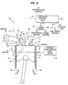
- FIGS. 1a and 1b illustrates the PCCI engine and control system of the present invention, indicated generally at 10.
- Fig. 1a shows a single engine cylinder 12 of the multi-cylinder reciprocating piston type engine shown in Fig. 1b.
- the PCCI control system of the present invention could be used to control PCCI combustion in an engine having only a single cylinder or any number of cylinders, for example, a four, six, eight or twelve cylinder internal combustion engine.
- the present PCCI control system is primarily discussed with reference to a four stroke engine, the present control system could be applied to a two stroke engine.
- the PCCI system of the present invention may be adapted for use on any internal combustion engine having compression, combustion and expansion events, including a rotary engine and a free piston engine.
- a piston 14 is reciprocally mounted in the cylinder to form a combustion chamber 13.
- the piston transmits forces generated by a combustion event into a conventional engine drive system.
- an intake air system 23 including an intake manifold 15 supplies intake air, or an air/fuel mixture to a respective intake port 26 associated with each cylinder 12.
- an exhaust gas system 27 including an exhaust manifold 17 handles air flowing from exhaust ports 31.
- One or more intake valves, such an intake valve 19 and one or more exhaust valves, such as exhaust valve 21, are moved between open and closed positions by a conventional valve control system, or a variable valve timing system, to control the flow of intake air or air/fuel mixture into, and exhaust gases out of, the cylinder, respectively.
- the PCCI system 10 includes a combustion sensor 16 for sensing or detecting an engine operating condition indicative of the combustion history and generating a corresponding signal 18.
- sensor 16 permits effective combustion control capability by detecting an engine operating condition or parameter directly related to, or indicative of, the time at which the combustion event occurs during the compression and ⁇ or expansion strokes, i.e. preferably the start of combustion (SOC).
- SOC start of combustion
- a cylinder pressure sensor may be provided on any or all engine cylinders for sensing, on a cycle-by-cycle basis, the SOC.
- the sensor 16 also provides other engine condition data, such as the combustion rate, combustion duration, combustion event or heat release location and end of combustion data, any one of which may be used instead of the start of combustion data.
- Any conventional means for detecting the start of combustion may be used, for example, by sensing the very rapid increase in the cylinder pressure.
- Other forms of sensors could be used including accelerometers, ion probes, optical diagnostics, strain gages and/or fast thermocouples in the cylinder head, liner or piston.
- torque or RPM sensors could be used to detect changes in engine torque and RPM associated with each combustion event.
- an emissions sensor could be used to detect emissions having a known correlation to the completeness of combustion.
- ECU 20 provides feedback control to an electronic control unit 20 (ECU).
- ECU 20 receives signal 18, processes the signal and determines an actual combustion history value, i.e. start of combustion value.
- the actual combustion history value is then compared to a predetermined desired combustion history value obtained, for example, from a look-up table.
- ECU 20 Based on the comparison of the actual combustion history value to the desired combustion history value, ECU 20 then generates a plurality of output signals, indicated at 22, for variably controlling respective components of the system so as to effectively ensure, in the preferred embodiment, that the SOC and completion of combustion occur between 20 degrees before top dead center (BTDC) during the compression stroke and 35 degrees after top dead center (ATDC) during the power stroke of the piston thereby minimizing NOx emissions while maximizing engine efficiency.
- the PCCI combustion control scheme is most preferably implemented in software contained in ECU 20 that includes a central processing unit such as a micro-controller, micro-processor, or other suitable microcomputing unit.
- PCCI system 10 may include various components for optimizing the combustion event.
- the objectives of the present system i.e. low nitrous oxide (NOx) emissions, high efficiency, etc, may be achieved using any one of the various control components, or any combination of the components.
- a compressor 24 may be provided along an intake air system 23 upstream of intake manifold 15 for varying the boost intake pressure.
- Compressor 24 may be driven by any conventional means, such as an exhaust gas driven turbine 25.
- a bypass circuit 33 including a waste gate valve 43 may be provided in a conventional manner.
- a second compressor or supercharger 58 may be provided upstream of compressor 24.
- Supercharger 58 is mechanically driven by the engine drive system.
- a charge air cooler 28 may also be provided downstream of compressor 24.
- an intake air heater 30 (such as a burner, heat exchanger or an electric heater) may be provided, for example, after cooler 28 as shown in FIG. 1b, or alternatively, upstream of compressor 24.
- an individual heater 29 may be provided in the intake port 26 associated with each cylinder 12 to provide quicker control of the intake manifold temperature for each cylinder to enhance both individual cylinder combustion control and balancing of combustion between the cylinders.
- Compressor 24, cooler 28 and heater 30 each include control devices for varying the effect of the particular component on the pressure/temperature of the intake air or mixture.
- a bypass valve or waste gate 43 could be used to regulate the amount of exhaust gas supplied from the associated exhaust system, which is connected to an exhaust duct 31, to turbine 25 thereby varying the intake pressure as desired.
- a control valve could be provided in the cooling fluid flow path supplied to cooler 28 to permit variable control of the cooling effect of cooler 28.
- various types of variable controls could be used to vary the heating effect of heater 30.
- Output signals 22 from ECU 20 are supplied to the various control devices to control compressor 24, cooler 28 and heater 30 so as to variably control the pressure and temperature of the intake air or mixture on a cycle-by-cycle basis.
- the PCCI system 10 may include a plurality of fuel supplies 32 and 34 for supplying fuels having different autoignition properties (for example, different octane or methane ratings, or activation energy levels) into the intake air flow.
- Fuel control valves 39 and 41 are used to control the amount of each fuel supply 32, 34 delivered, respectively.
- fuel may be supplied along the intake air path between cooler 28 and air heater 30 as shown in Fig. 1b.
- fuel could be introduced at various locations along the intake of the engine, such as upstream of the cooler, e.g. upstream of the compressor.
- the fuel could be injected, by for example an injector 35, into the respective intake duct 26 associated with each cylinder, as shown in Fig. 1a.
- variable compression ratio means 38 for varying the compression ratio so as to advantageously advance or retard the combustion event as desired.
- variable compression ratio means 38 may be in the form of a control mechanism for varying the shape of the combustion chamber or height of the piston to vary the effective compression ratio.
- the effective compression ratio could also be varied by varying the timing of closing of intake valve 19 as discussed more fully hereinbelow.
- the variations in the timing of opening and closing of the intake and exhaust valves may be accomplished using any conventional variable valve timing actuator system capable of receiving signals from ECU 20 and effectively varying the opening and/or closing of the valves in accordance with the principles set forth hereinbelow.
- in-cylinder diluent injection may be accomplished using an injector 40 for injecting a gas or liquid, e.g. air, nitrogen, carbon dioxide, exhaust gas, water, etc., into the cylinder to vary the temperature and the temperature distribution in the cylinder so as to control the combustion event.
- a diluent may be injected into intake duct 26 using, for example, an injector 42.
- the present PCCI system may also include a fuel injector 36 for injecting fuel 37, e.g. diesel fuel, directly into the combustion chamber.
- Fuel 37 would be injected either early in the compression event, preferably approximately between 180 degrees and 60 degrees BTDC, as described below, or later in the compression event near TDC.
- the start or initiation of the combustion (SOC) of the fuel/air mixture received from the intake duct may be varied by controlling the quantity of fuel 37 injected. For instance, an earlier combustion event may be achieved by increasing the quantity of fuel 37 while the timing of the combustion event may be delayed by decreasing the quantity of fuel 37 injected.
- the various control features for controlling the start of combustion and the combustion rate are controlled/varied to ensure optimum combustion throughout engine operating conditions so as to achieve low NOx emissions and high efficiency.
- Application of these control features will cause combustion to occur within a preferred crank angle range relative to the top dead center position of the engine piston.
- substantially all of the combustion event should occur between 20 crank angle degrees BTDC and 35 crank angle degrees ATDC.
- combustion would be initiated, preferably between 20 crank angle degrees BTDC and 10 crank angle degrees ATDC, and ideally, approximately between 10 degrees BTDC and 5 degrees ATDC.
- the duration of the combustion event will typically correspond to a crank angle in the range of 5 - 30 crank angle degrees.
- one or more of the control features listed below will be controlled to prolong the duration of combustion to approximately 30-40 degrees to achieve desirable peak cylinder pressures and reduced noise.
- optimal control of one or more of the following features will effectively control the start of combustion and/or the rate of combustion such that substantially all of the combustion event occurs between 20 crank angle degrees BTDC and 35 crank angle degrees ATDC.
- start of combustion occurs outside the above-stated crank angle range and/or the duration of combustion in the PCCI engine occurs over a broader crank angle range, or may extend beyond the limit described above.
- heat release duration may be in the range of approximately 21.5 - 25 crank angle degrees.
- Variation in the SOC is due to the sensitivity of PCCI combustion to the pressure and temperature history leading up to the particular combustion event. Very small variations in the compression ratio, the amount of trapped residual, wall temperatures, etc. have a significant effect on the pressure and temperature history.
- the present PCCI engine and method of operating the engine include control variables/features capable of compensating for, and controlling, these variations to achieve optimum PCCI combustion.
- control variables which can be used to effectively control the commencement of combustion and the combustion rate so as to ensure that substantially all of the combustion process occurs within the optimal crank angle limit, i.e. 20 degrees BTDC through 35 degrees ATDC while minimizing emissions and maximizing efficiency, may be classified in four categories of control: temperature control; pressure control; control of the mixture's autoignition characteristic; and equivalence ratio control.
- the temperature of the in-cylinder air/fuel mixture plays an important role in determining the start of combustion.
- the in-cylinder temperature may be varied to control the start of combustion by varying certain key control features, such as compression ratio (CR), intake manifold temperature (IMT), exhaust gas recirculation (EGR), residual mass fraction (RMF), heat transfer and temperature stratification.
- IMT intake manifold temperature
- PCP maximum allowable peak cylinder pressure
- Applicants have determined that small changes in IMT have large effects on many aspects of propane-fueled PCCI combustion.
- the combustion event can be advanced or retarded.
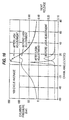
- Increasing the intake temperature will advance the start of combustion; decreasing the intake temperature will retard the start of combustion, as shown graphically in Fig. 8.
- This temperature control may be accomplished using heat exchangers or burners.
- a charge air cooler may be positioned along the intake manifold.
- a burner or heater in combination with a cooler offers exceptional intake temperature control.
- the exhaust products of the burner may be directly mixed with the intake air, the burner could use the intake air directly for its air supply, or the heat generated by the burner could be added to the intake air through a heat exchanger.
- the heat exchanger may use waste heat in engine coolant or exhaust gases to heat the intake air. Also, rapid control of IMT can be achieved by using a charge air cooler bypass. A regenerator (similar to that used in a Stirling engine) could be used to recover and transfer exhaust heat into the intake air through a heat exchanger thereby controlling the intake temperature. In addition, IMT could be varied by injecting fuel into the manifold in different phases, e.g. as a liquid or a gas. The change in the heat required for vaporization of a liquid fuel would reduce IMT. Of course, different types of fuels would have different effects on IMT.
- Applicants have also determined how residual and intake temperature, boost and combustion chamber and port wall heat transfer, affect in-cylinder bulk temperature throughout intake and compression, and also the effect on spatial temperature distribution at TDC. Specifically, Applicants compared the intake and compression events for an engine running on an air and propane mixture. Applicants determined that the temperature at the SOC is also determined in part by the reheating of the intake charge by existing heat energy. For the purposes of this application, reheat is defined as T(average in-cylinder @ intake valve closing (IVC)) - T(average intake manifold), that is, the difference between intake manifold temperature, i.e. temperature assigned at the inlet to the port and the in-cylinder bulk temperature at IVC. Applicants determined that reheat starts in the port and continues in-cylinder. Moreover, 56% of reheat was due to wall heat transfer and 44% due to mixing and boost for the condition examined. Clearly, heat transfer is very important in determining reheat.
- IVC intake valve closing
- ⁇ 11 K (46-35 K) temperature loss from IVC to TDC is due to cooler misfiring wall temperatures.
- walls heat the in-cylinder gases for the majority of the intake and compression event relatively fast rates of heat transfer out of the gas near TDC compression can result in cooler in-cylinder contents than if there were no heat transfer at all.
- Applicants have determined that as wall temperatures are increased, SOC becomes more advanced.
- the increased surface temperatures cause lower heat transfer to the combustion chamber surfaces thereby advancing combustion.
- Varying in-cylinder surface temperatures can be achieved by varying the cooling effect of the engine coolant and/or the lubricating oil on the cylinder/piston assembly.
- cylinder wall temperature may be difficult to use as a lever for effectively controlling SOC
- cylinder wall temperatures are one of the parameters considered when controlling SOC, particularly for starting or transient operation.
- Applicants have shown that there is a region of operating conditions where there are two stable solutions: one without combustion and cool walls, and one with combustion and hot walls.
- varying the surface to volume ratio in the combustion chamber can change the heat transfer and, therefore, can be used to control the combustion.
- wall heat transfer is seen to be the major contributor to spatial temperature distribution at TDC.
- Spatial temperature distribution is defined as the manner in which the temperature varies throughout a region, be it in the port, or in the cylinder at a particular crank angle.
- the start of combustion and/or the overall combustion rate can be positively affected.
- One way to vary in-cylinder temperature distribution is to use split intake ports arranged so that some of the incoming air/fuel mixture is warmer/colder than the rest of the incoming mixture.
- Another method is to introduce hot spots in the cylinder or to use a glow plug 44 (Fig. 1a).
- in-cylinder temperature distribution may be controlled by varying the temperature of the combustion chamber walls (e.g. the wall temperature of the cylinder liner, piston and/or engine head) by varying, for example, the temperature of the engine coolant, the temperature of the engine oil or the rate of cooling of the combustion chamber walls.
- the temperature of the engine coolant may be varied by controlling the flow through a coolant heat exchanger 46 positioned in the engine coolant circuit 47 by varying the flow through a bypass circuit 48 using a bypass valve 50. It was determined that wall heat transfer has similar impact on spatial temperature distribution for both firing and misfiring cylinders. Similarly, applicants also determined how residual temperature and wall heat transfer affect in-cylinder temperature distribution throughout intake and compression.
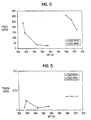
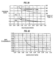
- a glow plug can be used to effectively control the SOC to a small degree. As shown in Fig. 10, once the glow plug is turned off, the SOC and EOC retard slightly. Also, GIMEP decreases significantly since less fuel is being burned. The decrease in the amount of fuel being burned also results in a decrease in the heat release rate as shown in Fig. 11. Between cycles #1 and #100, the glow plug was turned off and remained off until a time between cycles #300 and #400, at which point it was turned back on.
- glow plug 44 (Fig. 1b) could be used to positively control combustion to a limited degree.
- the present PCCI engine may include an end cylinder compensating means for achieving desired combustion chamber surface temperatures in the end cylinders to ensure better cylinder-to-cylinder temperature control thereby increasing the likelihood of stable combustion and very low NOx emissions.
- the end cylinder compensating means may include a system for reducing the effective cooling of specific cylinders, such as reducing piston cooling nozzle flow; increasing coolant temperature; or reducing coolant flow rate. Specifically, referring to Fig.
- the end cylinder compensating means may include an oil flow control system 70 including oil flow control valves 72 positioned in branch flow passages 74 delivering cooling oil to piston cooling nozzles 76 from an oil pump 78.
- control valves 72 can be controlled to vary the flow of cooling oil to the piston assemblies to vary the temperature of the piston and thus favorably influence the in-cylinder temperature.
- flow restrictions could be used instead of valves 72, or the nozzles 76 associated with the end cylinders may be designed with a smaller effective flow area than the remaining nozzles to permanently reduce the flow to these piston cooling nozzles.
- the number of nozzles operating could be varied by controlling the respective control valves associated with each nozzle.
- end cylinder compensating means may include an engine coolant flow control system 80 including a coolant pump 81 and coolant flow control valves or restrictions 82 positioned in branch passages 84 leading to the end cylinders 86 of the engine 88.
- the valves 82 are operated to reduce the flow of cold coolant delivered from a radiator 90.
- control valves 92 positioned in hot coolant return passages 94, are used to control the flow of higher temperature coolant, bypassing radiator 90, and delivered directly to the end cylinders.
- These systems all function to control the flow of coolant to the end cylinders to compensate for the fact that they are cooled more by the ambient surroundings so that the total cooling to each end cylinder is equal to each of the other cylinders.
- These systems can be used to assist in cylinder warm-up to improve engine startability and to provide enhanced control of cylinder combustion and cylinder-to-cylinder balancing.
- the end cylinder compensating means may, alternatively, or additionally, include end cylinders having an effective compression ratio nominally greater than the other cylinders to offset the extra heat loss.
- This compression ratio could be designed into the end cylinders so that the end cylinder compression temperature is equal to the middle cylinders. This approach is advantageous from a performance perspective since end cylinder combustion chamber surface temperatures would be enhanced for both start-up as well as warmed-up operation.
- This compression ratio difference may alternatively be accomplished through the camshaft valve lobe phasing.
- the end cylinders would have intake valve closing (IVC) near bottom dead center (BDC) so that the effective compression ratio (CR) is approximately equal to the geometric CR.
- the middle cylinders could then have a retarded IVC which would produce a lower nominal effective CR than the end cylinders.
- PCCI premixed charge, compression ignition
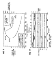
- valve events can have a significant effect on the temperature at TDC and therefore is an effective tool for controlling the start of combustion as suggested by analytical results shown in Fig. 14.
- varying valve events has the following effects: TABLE I modified event baseline effect of advancing valve timing relative to baseline effect of retarding valve timing relative to baseline EVC -357° traps hot residual which advances SOC exhaust blown back into intake which advances SOC EVO 135° no effect no effect IVC -167° Miller cycle - lowers effective CR which retards SOC at these particular conditions, retarding slightly improves breathing; retarding-further reduces effective CR which retards SOC IVO 341° allow hot exhaust to flow into intake which advances SOC restricts flow from intake manifold which has minimal effect on SOC
- exhaust valve closing plays a significant role in determining the amount of combustion products that remain in, or are made available to, the combustion chamber from one combustion event to the next event, i.e. the residual mass fraction (RMF).
- the residual exists at a higher temperature than the incoming charge and therefore heats the charge for the next combustion event.
- the timing of exhaust valve closing can be used to adjust the in-cylinder temperature and therefore controlling the SOC.
- the residual mass fraction can be increased in the individual cylinder by an early exhaust valve closing event.
- RMF residual mass fraction
- the timing of flows into and out of such a chamber may help manage the timing of the beginning of rapid energy release in cylinder. Additional sources of local heat input may be able to supply such a fast reaction initiation. This might be a heated glow plug or a thermally isolated mass.
- the residual mass fraction is also sensitive to the exhaust manifold back pressure (EMP).
- EMP exhaust manifold back pressure
- the residual mass fraction can be increased thus increasing the temperature of the charge which, in turn, advances combustion.
- Applicants have determined that raising EMP does have the expected result of advancing SOC.
- Applicants have determined that the increase in temperature is nearly linear with increase in EMP, with all other things being held constant. For a 1 bar increase in EMP, temperature at TDC increased about 10 K. Therefore, considering the practical range of EMP, controlling EMP seems to be a relatively weak lever in controlling SOC on a four cycle engine.
- EGR hot exhaust gas recirculation
- a high pressure EGR circuit 54 may be used to direct hot exhaust gas from upstream of turbine 25 into the intake system 23.
- EGR circuit 54 includes a high pressure EGR control valve 60 for controlling the recirculation of exhaust gas.
- a low pressure EGR circuit 62 and control valve 64 may be used to direct a flow of low pressure EGR from downstream of turbine 25 into the intake system 23.
- EGR is especially effective in increasing the intake manifold temperature when introduced upstream of the compressor 24 (assuming the effect of adding EGR is not cancelled by additional charge air cooling).
- Exhaust gas recirculation has more utility in PCCI engines because the exhaust gas of such an engine will contain less particulates and thus the exhaust gas can be recirculated to the ideal upstream location (intake of compressor of turbocharger).
- the intake of the compressor is the best location because the pressure differential is almost always favorable.
- the fresh intake air and hot EGR mixture will get compressed by the compressor thereby providing heating and mixing.
- By introducing the EGR upstream of the compressor and increasing the compressor inlet temperature the result is a much higher compressor outlet temperature than if the EGR is introduced after the compressor.
- Introducing EGR into the intake of the compressor is very difficult in normal diesel engines because the particulates in the exhaust gases of the engine "gum up" the compressor.
- an improved engine 100 which benefits from the PCCI engine and control system of the present invention by operating a limited number of a plurality of cylinders in a PCCI mode while operating the remainder of the cylinders in a diesel mode.
- five cylinders 102 in a six cylinder engine may be operated in the diesel mode while one cylinder 104 is operated in a PCCI mode.
- This engine also includes an EGR system 106 associated only with the PCCI cylinder 104 and separate from an exhaust system 108 associated with the diesel cylinders 102. The pressure of the piston in the PCCI cylinder 104 is used to force the exhaust gas into the intake system.
- the EGR system 106 includes an EGR cooler 110 utilizing, for example, engine coolant, which cools PCCI exhaust gas before recirculating the gas to the.upstream side of a compressor 105.
- engine coolant which cools PCCI exhaust gas before recirculating the gas to the.upstream side of a compressor 105.
- the exhaust gas could be delivered to the intake manifold 112 serving only diesel cylinders 102.
- a well known problem confronted in the use of EGR in diesel engines is the excessive amounts of particulates and NOx present in diesel engine exhaust gas.
- the improved engine 100 permits a diesel engine to benefit from EGR while substantially avoiding the drawbacks associated with heavy particulate diesel exhaust thereby providing a less complex and costly system.
- the PCCI EGR from cylinder 104 could more easily be introduced upstream of the compressor without fouling the compressor.
- the low NOx emissions of the PCCI EGR reduce the formation nitric acid thereby reducing corrosion in the engine. Applicants have shown that the engine of Fig. 19 lower
- the SOC is variable control of the compression ratio (CR) of a cylinder.
- CR compression ratio
- both the temperature and the pressure histories can be controlled.
- Increasing the compression ratio advances the combustion event. Decreasing the compression ratio retards it.
- the compression ratio may range from 24:1 (to promote cold starting) to 12:1 (to permit control over the start of combustion and limit the peak combustion pressures).
- the range of compression ratios would depend on, among other factors, the type of fuel used (more specifically its autoignition properties), for example, natural gas or propane.
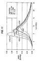
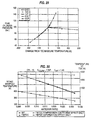
- Applicants have determined the effect of compression ratio on PCCI combustion. For example, referring to Fig. 20, applicants have shown that varying the compression ratio is a large lever in changing in-cylinder temperature and therefore SOC. As shown in Fig. 21, applicants have shown that variations in compression ratio significantly affects the location of the SOC relative to TDC.
- the compression ratio can be varied by varying the geometric compression ratio, i.e. using a control mechanism to vary the physical dimensions/shape of the combustion chamber.
- the present invention includes a compression ratio varying device 38 for varying the geometric or the effective volume of the combustion chamber during engine operation to achieve a desired SOC.
- the compression ratio varying device may be a mechanical device for causing compression heating of the charge near TDC by changing the geometric volume of the combustion chamber.
- the compression ratio varying device may include a movable auxiliary piston or plunger which moves to extend into the combustion chamber at a crank angle near TDC to decrease the combustion chamber volume thereby increasing the compression ratio and heating the charge sufficiently to allow ignition to start.
- the key function of the plunger is to displace some of the charge near TDC. Therefore, the shape and location of the plunger in the combustion chamber will not be critical to its function, except to the extent that the plunger affects the crevice volume.
- the size of the plunger will be based on the desired compression ratio control range and may be estimated by the following example:
- the modified compression ratio should be sufficient to allow a large enough increase in temperature and pressure to cause compression ignition for a fuel/air mixture that would not ignite without the plunger.
- the engine's compression ratio and the size of the plunger are easily changed during the design stage of the engine.
- different fuels and intake temperatures could require different plunger sizes and compression ratios.
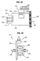
- the plunger 150 may be positioned in a bore 152 in the cylinder head 154 and operated by a cam 156 rotated in predetermined timed relationship to the movement of the engine piston 158.
- a retraction spring 160 biases the plunger toward cam 156 to increase the size of combustion chamber 162.
- a plunger 170 may be hydraulically operated by a pressurized supply of fluid, e.g. fuel, delivered to a chamber 174 by a hydraulic circuit 172 connected to, for example, a jerk pump or common rail system.
- Fig. 22c illustrates another hydraulically actuated embodiment in which a plunger 180 is assisted by a spring 182, positioned in a chamber 184 formed adjacent one end of plunger 180, to allow energy to be stored in the spring.
- a retaining mechanism e.g. hydraulic, electromagnetic or mechanical, (not shown) maintains the plunger in the unextended position.
- a hydraulic fluid supply system 186 forces plunger 180 down (at this point the retaining system no longer holds the plunger). This downward motion is heavily assisted by spring 182. After combustion, plunger 180 moves back up recompressing spring 182 thereby returning energy to the spring. To optimize this energy extraction process, the hydraulic chamber 184 bleeds down at a rate controlled by a valve 188.
- Fig. 22d illustrates yet another embodiment in which a spring 190, biasing a plunger 192 into the extended position, is strong enough to overcome the gas pressure in the combustion chamber before combustion.
- a bleed down valve 194 connecting a chamber 196 is opened and the spring 190 pushes plunger 192 into the extended position in the combustion chamber 162 causing the charge to ignite and the pressure in the combustion chamber 162 to increase.
- plunger 192 is pushed back up against spring 190.
- a high pressure supply 200 supplies hydraulic fluid to chamber 196 to ensure plunger 192 moves back up into the retracted position.
- a low pressure hydraulic fill supply 202 including a one-way valve 204, may be used to fill the chamber 196 below plunger 192.
- the compression ratio may also be varied by providing an opposed piston engine design having variable phase shifting to permit the compression ratio to be varied during operation by changing the phase of rotation between two crankshafts.
- the opposed piston engine may be of the type disclosed in U.S. Patent No. 4,010,611 or of the interconnected cylinder type with variable phasing as disclosed in U.S. Patent No. 4,955,328, the entire contents of both of these references being hereby incorporated by reference. Alternatively, referring to Fig.
- the compression ratio could be varied using a phase shifting mechanism 210 including a conventional differential assembly 211 connected between an input shaft portion 212 of one of the crankshafts 214, 216 associated with respective pistons 218, 220 and an output shaft portion 222 of the same crankshaft 214 to permit the portions of the crankshaft to be rotatively shifted relative to one another.
- Crankshafts 214 and 216 are connected via a conventional gear assembly 223 for transferring power to a driven shaft 225.
- the differential 211 includes a ring gear 224 mounted on one end of input shaft portion 212, an arm 226 extending from ring gear 224 and a gear assembly 227 mounted on the opposing ends of shafts portions 212, 222.
- a rotator mechanism 228, including a pinion gear 230, is operatively connected to ring gear 224 to rotate the ring gear when a change in the phasing between the crankshafts is desired.
- ring gear 224 remains stationary, shafts portions 212, 222 remain in phase.
- arm 226 rotates causing a change in the phasing between shaft portions 212, 222.
- the rotator mechanism 228 would, therefore, be used to adjust the relative phasing of the input shaft to the output shaft, thereby adjusting the phasing of the two crankshafts and the compression ratio.
- crankshafts per cylinder could be used to eliminate the inherent side thrust imparted by the crankarm in the single crankshaft design.
- the effect of the maximum possible compression ratio on the sensitivity to CR on phasing should be noted. It might be advantageous to have a geometry where the pistons interfere with each other at "zero" phasing. Of course, this set up would operate with non-zero phasing all the time.
- the compression ratio could be varied over a very large range using an opposed piston arrangement with variable phasing.
- the slope of the change in compression ratio with phasing depends on the amount of clearance or negative clearance between the pistons at TDC with 0° phasing.
- the slope of the curve would be steep enough that the desired range of compression ratio could be achieved within a limited amount of phasing, and not so steep that the phasing needs to be too precise.
- the effective compression ratio may be varied with variable valve timing. Specifically, as shown in Table I, advancing of the intake valve closing lowers the effective CR while significant retarding of the IVC also reduces effective CR. However, changing valve events can have a very large effect on the breathing of an engine, and thus the air/fuel ratio, in comparison to varying the geometric compression ratio (assuming that the fuel flow rate is held constant).
- the steepest change in airflow with TDC temperature is when IVC is changed. As IVC becomes earlier, the TDC temperature is lowered, but airflow is severely restricted possibly undesirably changing the equivalence ratio. In this case, an increase in boost accompanying earlier IVC could be used to maintain a constant air flow rate.
- variable geometric compression ratio appears to be the most effective of the control features.
- Applicants have also determined that very high compression ratios are needed for combustion at low intake temperatures. For example, it has been found that at intake temperatures of 0, 20, and 40°F, no combustion occurs when the corresponding compression ratios are below 35, 33, and 30, respectively. At warmed up conditions, the desired compression ratio is approximately 15, which means that a change of approximately 20 compression ratios would be needed to cover these conditions. Due to the very high compression ratios required under these conditions, peak cylinder pressures are also high and in some cases greater than 200 bar. As a result, intake air heaters and/or some other method of starting in cold conditions may be more practical than using variable compression ratio alone. Also, maintaining a lower compression ratio will allow a higher GIMEP to be achieved before hitting the peak cylinder pressure limit.
- Another method of controlling the temperature is to introduce water into the intake manifold or directly into the cylinder.
- Applicants have shown that when the nitrogen in the intake air is completely replaced with water, the water will likely result in a lower flame temperature (205 K lower) due to dissociation.
- the ignition delay increased slightly (by 0.04 msec) and the peak reaction rate dropped by about 50%.
- water was added into the intake manifold e.g. water fumigation
- the chemical effect although small, is to slightly retard the SOC.
- liquid water injection into the intake manifold effectively cools the intake manifold due to the vaporization of the liquid to steam.
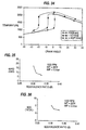
- IMT and TDC temperatures are significantly decreased as shown in Fig. 30.
- the impact of water injection on temperature at TDC is mostly due to the decrease in IMT, not due to the change in the ratio of specific heats.
- the effect on IMT should be viewed as an upper limit.
- the SOC may also be controlled by controlling the pressure in the combustion chamber.
- One way of controlling in-cylinder pressure is to use a compression ratio varying device to vary the pressure in the combustion chamber. Although varying the compression ratio ultimately varies both the pressure and temperature of the charge, the pressure is directly changed. An increase in the compression ratio will tend to increase the pressure at TDC, and a decrease in compression ratio will decrease pressure at TDC. Applicants have shown that increasing the in-cylinder pressure advances the start of combustion and decreasing the in-cylinder pressure retards the SOC. Any of the compression ratio varying devices discussed hereinabove with respect to temperature control may be used.
- a second way of controlling the in-cylinder pressure is to vary to the intake manifold, or boost, pressure (IMP).
- the timing of the SOC has been shown to be a function of pressure.
- Applicants have determined the effects of varying IMP on combustion and engine operation.
- the engine conditions for one engine study were 1200 RPM, 355.7K ⁇ IMT ⁇ 357.4K, 0.256 ⁇ ⁇ ⁇ 0.263.
- IMP was varied. Maintaining these conditions while increasing IMP required increasing air flow and fuel flow.
- Figs. 31a and 31b show that the duration of heat release decreases as IMP increases both in the crank angle domain and the time domain.
- Fig. 31d shows that SOC occurs earlier as IMP increases.
- Fig. 31c showing results from another study, clearly indicates that increasing the boost pressure significantly advances the heat release event.
- Fig. 31e shows that FSHC emissions decrease as IMP increases, indicating more complete combustion.
- Fig. 31f shows that GIMEP increases as IMP increases, mostly due to the increase in complete combustion, and, to a lesser extent, more fuel.
- Fig. 31g shows that gross indicated thermal efficiency increases as IMP increases, partly due to more complete combustion.
- Fig. 31h shows that FSCO emissions decrease as IMP increases, apparently due to more complete combustion.
- Fig. 31i shows that FSNOx emissions are not significantly affected by IMP.
- Fig. 31j shows that coefficient of variation (COV) of GIMEP decreases as IMP increases.
- Fig. 31k shows that PCP increases as IMP increases.
- Fig. 311 shows that estimated noise increases as IMP increases.
- Fig. 31m shows that as IMP increases, smaller gains in GIMEP cause larger rises in PCP. This effect is due
- varying IMP can be an effective way of controlling the SOC and the duration of combustion. Increasing the IMP tends to advance SOC while decreasing the duration of heat release. Likewise, decreasing the IMP tends to retard SOC while increasing the duration of heat release.
- the fuel flow rate would remain virtually constant, and the boost pressure would be increased to advance the start of combustion or decrease the boost to retard the start of combustion.
- an air compressor, a turbocharger, a supercharger such as driven by an engine power take-off, or an electrically powered compressor, could be used. For a given power level, and, therefore, for a given fuel flow rate, there typically exists a preferred intake pressure and temperature.
- Throttle 53 would also be used when operating a multi-mode PCCI engine in a spark ignited mode as described hereinbelow.
- a throttle could alternatively be located at other locations in the intake system, such as in the intake manifold.
- the autoignition properties of the air/fuel mixture may be controlled by injecting a gas, e.g. air, oxygen, nitrogen, ozone, carbon dioxide, exhaust gas, etc., into the air or air/fuel mixture either in the intake system, e.g. preferably in the port using, for example, injector 42, or in the cylinder directly using, for example, injector 40, thereby providing control over the start of combustion and the combustion rate.
- a gas e.g. air, oxygen, nitrogen, ozone, carbon dioxide, exhaust gas, etc.
- Applicants have examined the effect of adding reactive species to the air/fuel mixture on the combustion process.
- One study was performed using an equivalence ratio of 0.3, a temperature at BDC of 389 K, pressure at BDC of 3 bar, and propane as the fuel.
- the compression ratio was 14.5, and the engine speed was 1800 RPM.
- the engine geometry used was for a Cummins C series engine.
- the nitrogen, oxygen, and fuel concentrations were held constant at 0.771, 0.216, and 0.0123, respectively, for all cases.
- the mole fraction for the reactive species added was 0.000411 for all cases.
- the reactive species examined were H 2 , H 2 O 2 , OH, CO, O, HO 2 , H, and O 3 .
- Fig. 32 shows the temperature versus crank angle. Although CO and H 2 advanced the SOC by less than 0.5 crank angle degrees, all other species significantly advanced the SOC, with O 3 (ozone) causing the largest change in the SOC. Therefore, small concentrations of most common radical
- Fig. 33 illustrates the effects of additional ozone on advancing the SOC.
- the increase in temperature indicates the start of the combustion event.
- ozone can be used in several ways to advantageously control the combustion in a PCCI engine.
- adding O 3 to the intake could be used as a cold starting aid for PCCI and diesel engines.
- O 3 could be produced "on board" through a simple electro-chemical reaction.
- Ozone generators are commercially available.
- the ignition delay of a diesel engine could be reduced by adding O 3 to the intake. This would reduce the premixed burn fraction which would then lower NOx emissions and reduced noise.
- Another method of varying the effect of oxygen on the combustion process is to dilute the mixture with EGR.
- an engine EGR system was plumbed from the exhaust manifold to the compressor inlet. Because the EGR is mixed in upstream of the aftercooler, and in the present study, the aftercooler exit temperature was controlled and held fixed, the EGR should not have significantly effected the temperature at SOC.
- fuel rate and intake manifold temperature were held constant. As the EGR rate was increased, exhaust manifold pressure decreased, which in turn decreased air flow on this turbocharged engine. The fuel rate was held constant, so the fresh equivalence ratio increased.
- Another technique for modifying the autoignition properties of the air/fuel mixture to control SOC and the duration of combustion is to vary the octane, methane or cetane number of the charge by, for example, by providing two or more fuels have different octane, methane or cetane numbers.
- the fuel supply can be either selectively switched between the fuels or the fuels can be mixed. This technique makes it possible to retard or advance the combustion event.
- a fuel which tends to autoignite more readily could be controllably mixed with a fuel that tends to autoignite less readily (or a fuel that ignites at a high temperature and a fuel that ignites at a low temperature could be used) to enable direct control over the timing of ignition and rate of combustion by changing the ratio of the fuels that are present in the combustion chamber during the combustion event.
- propane, octane and heptane have significantly different effects on the SOC.
- a fuel additive such as a controlled amount of propane, ethane, or other hydrocarbons, such as engine lubricating oil, that change the autoignition properties of the fuel to advance or retard the start of combustion.
- a fuel additive such as a controlled amount of propane, ethane, or other hydrocarbons, such as engine lubricating oil
- any method that changes the fuel's octane/methane number or the activation energy of the fuel can be used to advance/retard combustion.
- Applicants have determined that there is a significant sensitivity of start of combustion to octane number. This effect was independent of intake manifold temperature.
- the start of combustion was retarded approximately 7° for an increase in octane number from 80 to 100.
- Fig. 1b illustrates one system for balancing combustion between cylinders of a multi-cylinder engine.
- the system uses port injection of fuel on the engine with two types of supplies per cylinder - supply 32 to inject liquid fuel and supply 34 to inject gaseous fuel.
- the supplies 32 and 34 are shown feeding into a single passage for delivery to the intake port, the supplies may include separate delivery passages connected to the intake port at different locations.
- Liquid fuel will decrease intake charge temperature by the heat of vaporization of the liquid fuel.
- the temperature at TDC compression, and therefore SOC can be controlled by varying the amount of liquid versus gaseous fuel.
- the gaseous and liquid fuel can be the same fuel in different states, e.g. propane, or different fuels, e.g. gaseous natural gas and liquid gasoline, such as indolene. It is important that the port injection system have good separation between cylinders and sequential (timed to intake event) injection is likely to be required. During operation, a cylinder that is "going out” would be given more gaseous fuel and a cylinder that is “too hot” would be given more liquid. This method can be used to achieve about a 20 degree temperature difference.
- One of the supplies could be lubricating oil or ozone while the other supply could be a fuel having a high resistance to ignition, e.g. a high octane number, to permit the SOC to be effectively controlled by varying the amount of oil or ozone added to the mixture. Also, by using the engine's lubricating oil supply, or using ozone created by the engine during operation, an additional supply of fuel/additive can be avoided.
- equivalence ratio is equal to fuel/air ratio divided by stoichiometric fuel/air ratio (if ⁇ 1, fuel deficient; if > 1, fuel excess). Combustion needs to be slowed down in a PCCI engine because fast combustion leads to high noise, lowered efficiency and high peak cylinder pressure. If different temperatures and/or equivalence ratios can be achieved throughout the charge of air/fuel at or near point of ignition, the resulting rate of combustion will possibly be slowed down thus advantageously lengthening the duration of combustion.
- the equivalence ratio could be increased by increasing the fuel flow to the cylinder without a corresponding increase in intake air flow, or by decreasing the intake air flow.
- the equivalence ratio could be lowered by decreasing the fuel flow to the cylinder without a corresponding decrease in air flow, or increasing the air flow rate.
- Variations in the quantity of fuel delivered to a cylinder is varied by controlling the operation of fuel control valves 39, 41, and/or fuel injectors 35, 36 in a known manner.
- the variations in the air flow rate could be achieved by, for example, variably controlling compressor 24 to vary boost pressure.
- Applicants have determined that it may be possible, although not necessarily desirable, to maintain PCCI combustion at very rich equivalence ratios, e.g..5, if IMP and IMT are sufficiently low to prevent the peak cylinder pressure limit from being exceeded. It will be difficult to start an engine at the low boost and IMT levels needed for maintaining low cylinder pressures at such rich equivalence ratios. The very advanced heat release, loud knock, and combustion roughness make running at this condition undesirable. A lower CR for retarding SOC may improve these aspects.
- auxiliary combustion chamber concept may be a mechanism for achieving the desired stratification, thereby enabling better control over the start of combustion.
- conventional auxiliary combustion chamber designs typically used on small engines having indirect injection (IDI), and large spark ignited engines using natural gas fuel, could be used.
- Applicants have determined that it would be desirable to operate under slightly leaner conditions than the original target.
- a smaller turbine casing was used to decrease the compressor pressure ratio and exhaust manifold pressure ratio, but a high BSFC penalty is paid, as shown in Fig. 40.
- Figs. 41 and 42 illustrate the higher PMEP losses with the smaller turbine casing and the higher BSFC.
- the rotor speed is much higher and, in fact, near the limit on rotor speed as seen in Fig. 43 (rotor speed limit 120-125k rpm range).
- Applicants discovered that there is a lower limit on the size of the turbine casing used due to the losses incurred with the high back pressure and with reaching the rotor speed limit.
- a mechanically driven supercharger in conjunction with a turbocharger.
- the supercharger would be upstream of the compressor so that the turbine bears less of a burden for producing boost.
- Some BSFC penalty would be incurred for the shaft work absorbed by the supercharger; however, the BSFC penalty is less than the very high penalty incurred with the very small turbine. Because the supercharger is driven mechanically from the shaft, there should be no trouble getting the desired air flow.
- the turbine then can be sized somewhat larger, and should not approach the speed limit and should not have extremely high back pressure.
- Applicants have also determined the effect of engine speed on SOC.
- the time of autoignition depends on the temperature and pressure histories. By changing the engine speed, these histories are changed. It is possible to advance the combustion event by reducing the engine speed, and to retard the combustion event by increasing the engine speed. Specifically, a 75% increase in engine speed, from 1000 to 1750 resulted in a 1.5% increase in the start of combustion pressure and a 2.8% increase in the start of combustion temperature. In addition, a 75% increase in engine speed decreased the heat release rate duration by 0.81 ms (only a 23% decrease) which corresponds to an increase in heat release duration of 1.7 crank angle degrees (only an 8% increase).
- engine speed is not viewed as an effective combustion control variable.
- engine speed could be used to provide some control over combustion is in an application where the engine drives a generator or alternator.
- control variables are used to control the SOC and the duration of combustion to achieve optimum PCCI combustion.
- One key consequence of efficient, optimum combustion is reduced emissions.
- Applicants have shown that a PCCI engine can achieve NOx emission levels that are well below any other NOx emission levels ever demonstrated by applicants using diesel and natural gas engines, and well below future emissions standards as shown in Fig. 44.
- propane as the fuel results in the lowest NOx emissions relatively to diesel fuel and gasoline.
- Applicants have also determined the effect of the control variables and other factors on emissions of a PCCI engine.
- Engine speed has little effect on the quantity of NOx emissions. Although a 75% increase in engine speed approximately tripled the FSNOx, the levels of NOx emissions produced were still extremely low. Also, as equivalence ratio becomes richer, fuel specific NOx generally increases, but still remains at extremely low levels.
- Fig. 45 applicants have determined that engine speed appears to affect FSCO and FSHC emissions more significantly. As shown, below a certain critical speed, virtually all of the fuel burns, FSHC are low and FSCO is low. Just above the critical speed, the fuel partially burns, resulting in higher FSCO emissions.
- UHC unburned hydrocarbons
- CO unburned hydrocarbons
- the present PCCI engine may include one of several designs to minimize UHC.
- the present crevice minimizing designs result in a low crevice volume; keep the fuel away from any existing crevices; or cause the crevice volume to burn appropriately.
- the designs shown in Figs. 48a and 48b are most easily implemented in a ported two stroke cycle engine.
- the engine has a single piece head and liner combination 300, although a two-piece system could be used.
- the bore 304 increases to eliminate the crevice around the top land 306 of piston 308. There are no crevices in the cylinder head, as it is a single piece without valves, gaskets, etc.
- a second embodiment of the crevice minimizing design may similarly include a one-piece head and liner 310.
- the piston 312 has a very aggressive cutback 314 forming the top land to enlarge the crevice volume 316 between the top land and the liner.
- the crevice volume 316 is now so large that it will no longer quench combustion in this area thus allowing fuel in this volume to burn resulting in reduced UHC.
- Fig. 49 illustrates yet another embodiment including a cup or chamber 320 formed in the cylinder head 322 of the engine.
- the fuel injector 324 is positioned to inject fuel directly into cup 320 early in the compression stroke. Because air is pushed into cup 320, the fuel does not exit the cup.
- the products can pass through the relatively large passage or throat 326 between the cup 320 and the main cylinder 328.
- the fuel is well mixed because of the turbulence of the air entering the cup. Because there are no crevices in the cup and because the fuel does not leave the cup until after combustion is completed, UHC are extremely low.
- the cup could easily be coated with a thermal barrier coating to reduce heat losses.
- Figs. 50a and 50b illustrate a cup design for a four stroke engine.
- the exhaust and intake valves 330 are arranged around a cup 332 in the head 334.
- Cup 332 may be positioned directly above the combustion chamber 336 as shown in Fig. 50a or offset to allow more room for the valves 330 as shown in Fig. 50b.
- Another possibility is to include a small auxiliary valve in the cup to allow the products to exit the cup more efficiently. This valve could open after the main exhaust valve opens so that the auxiliary exhaust valve in the cup would not open against a high pressure.
- the auxiliary exhaust valve could be electronically operated. The timing of opening and closing of this valve could be used to vary the residual mass fraction which would allow control over the SOC using this auxiliary valve.
- an opposed piston engine as discussed hereinabove, may be used to substantially reduce the crevice volume by avoiding a cylinder head and the associated crevices.
- FIG. 1a another embodiment of the present invention for reducing emissions is disclosed.
- this embodiment controls UHC and CO by heating the upper portion of the cylinder liner 49 to cause oxidation of the charge in the crevices.
- a heater 51 is incorporated into the upper part of the liner.
- the heater could be any type of heater capable of effectively producing heat, such as an electrical resistance heater.
- the heater heats the gas in the crevice above the top ring when the piston nears TDC. This heating will cause the gas to be less dense resulting in a smaller mass of charge remaining in the crevice.
- the charge leaving the crevice will be at a higher temperature due to the heating thus increasing the tendency of the charge to react and form CO 2 instead of CO and UHC.
- a glow plug may be used to heat the combustion gases to reduce emissions by enabling a larger portion of the crevice volume to be burned. It has been determined by applicants that a glow plug will have only a slight impact on the SOC. Since SOC changes only slightly when the glow plug is turned on, it does not appear that the glow plug is initiating combustion. It is more likely that when the glow plug, which was located in a spacer plate, is turned on, it gradually warms up the gas in the crevice volume. This increase in temperature is sufficient to speed up the onset of rapid combustion, and burn more of the fuel than would have been burned without the glow plug on, resulting in a slight increase in GIMEP.
- the present engine may also be operated as a multi-mode engine which changes modes of operation based on the operating conditions or needs of the particular application.
- the engine may be operated on diesel fuel only as a conventional diesel engine, as a modified diesel engine with diesel fuel being injected earlier in the compression event than the conventional diesel engine, as a spark-ignited engine using spark plug 56 (Fig. 1a) or as a PCCI engine.
- spark ignited/compression ignited DI (direct injection) variable compression ratio engine provides a combination of low emissions, high power density, and ease of starting.
- This engine operates in the following different modes depending on the current operating conditions/needs of the engine.
- the key here is to take full advantage of the variable compression ratio. Starting of the engine can be achieved with spark ignition at a lower compression ratio and then transitioning to high compression ratio, lean PCCI operation for low NOx. For less severe (e.g. not as cold) conditions, engine starting could be achieved directly with very high compression ratio PCCI operation. At low and medium loads, the engine can operate in a PCCI mode as the compression ratio is adjusted to keep the start of combustion near the optimum crank angle. For high load requirements, the air/fuel ratio can be enriched, compression ratio lowered, and the engine can be spark ignited. In order to handle sudden transients, the engine may go into one of the late injection modes where richer air/fuel ratios are possible without engine damage.
- ECU 20 functions with a control strategy for controlling the various controlled features of the engine to effectively switch between, and operate in, the different modes in order to achieve a variety of objectives.
- the multi-mode engine achieves low NOx emissions in the PCCI mode while enhancing startability by providing a high compression ratio or spark ignition.
- the engine can achieve a high cylinder pressure at high BMEP by switching to a lower compression ratio spark-ignited mode.
- the multi-mode engine also permits stable combustion to occur after switching to late injection which results in a stratified charge by rapidly adjusting the compression ratio.
- fuel consumption can be effectively controlled using high compression, PCCI operation and stratified charge operation requiring no throttling which have excellent thermal efficiency.
- This operation also improves transient response by going from PCCI to late injection, stratified charge to suddenly enrich the mixture.
- This multi-mode engine can also effectively minimize knock, and therefore knock damage, by effectively operating at lean PCCI or stratified charge or low compression ratio, lean burn or stoichiometric conditions.
- the engine operates to effectively control the start of combustion during PCCI operation by varying, for example, as discussed hereinabove, the temperature and/or the equivalence ratio and/or the pressure and/or the air/fuel mixture autoignition properties.
- This engine could run on a variety of fuels like gasoline or diesel fuel.
- FIG. 51 shows a comparison of the normalized heat release rate versus crank angle for the three different diesel pilot injection quantities into a PCCI engine operating on propane. A micro-pilot injection of .1% resulted in good heat release placement with no measurable increase in FSNOx.
- a diesel pilot of an amount estimated to supply 3.6% of the fuel energy resulted in a heat release curve having substantially the same shape as the previous case.
- the SOC is slightly more advanced than that of the .1 % case despite a lower IMT and constant equivalence ratio.
- FSNOx emissions have increased over the .1 % case from zero to 3.9 g/kg.
- the final curves illustrates the heat release for a case with ⁇ 18 % of the fuel energy coming from the diesel pilot.
- the heat release rate curve is shaped the same as the classic diesel heat release rate curve with a premixed burn spike and a diffusion burn region.
- the FSNOx (15.3 g/kg) and FSHC (478 g/kg) are significantly higher than in the cases with smaller diesel pilots.
- Applicants have also studied the control of noise associated with PCCI combustion.
- Level of noise generated by PCCI combustion is related to the knock intensity.
- knock intensity is decreased, noises decreases.
- lowering cylinder pressure for example, by retarding the SOC, substantially decreases the knock intensity and, therefore, noise.
- the present engine and control system permits continuous PCCI combustion with minimal noise by avoiding excessive peak cylinder pressures while maintaining the required cylinder pressure necessary for efficient, low emission PCCI combustion and the desired power output.
- the control system of the present invention operates to actively and variably control the mixture's temperature, pressure, autoignition characteristic and equivalence ratio to ensure that the combustion event occurs between 20 crank angle degrees BTDC and 35 crank angle degrees ATDC.
- the control system achieves this function by using combustion sensor 16, e.g. pressure sensor, to signal the start of combustion or the location of the heat release event for each cycle.
- ECU 20 which receives the signals from sensor 16, determines whether the SOC is occurring within a predetermined crank angle range and determines whether the duration of combustion is within a predetermined desired crank angle range.
- One conventional way for the ECU to determine the optimum SOC would be to use a look-up table.
- ECU 20 determines the appropriate control variable or variables to adjust, and generates and sends the appropriate signal 22 to the chosen control mechanism or mechanisms, e.g. air cooler 28, heater 30, glow plug 44, fuel control valves 39, 41, variable compression ratio device 38, etc., as discussed hereinabove.
- the control variables are varied as required to maintain the timing of the start of PCCI combustion preferably between 20 crank angle degrees BTDC and 10 crank angle degrees ATDC, and to maintain the duration of combustion in the range of 5-30 crank angle degrees.
- the conditions in the cylinders e.g. temperature and/or pressure
- the intake air temperature could be raised using heater 30 and/or a glow plug 44, and/or the in-cylinder walls heated using a cylinder wall heater 51 and/or an engine coolant/lubricating oil heater.
- the in-cylinder pressure and temperature could be increased using variable compression ratio device 38.
- Another effective control feature for enhancing startability is to add small amounts of ozone to the intake air supply using injector 42, or into the cylinder using injector 40.
- one of the fuel supplies could have a high autoignition property, e.g.
- the engine may be operated in a non-PCCI, for example, as a spark-ignition, dual fuel or diesel engine, during starting of the engine.
- a non-PCCI for example, as a spark-ignition, dual fuel or diesel engine, during starting of the engine.
- One or a combination of these controls are varied, in accordance with the principles discussed hereinabove with respect to each control feature, to cause PCCI combustion to occur.
- the ECU will monitor the start of combustion and duration of combustion by receiving combustion data, e.g. pressure signals, from sensor 16 throughout engine operation.
- the control system of the present invention will vary one or more of the control variables, that is, temperature, pressure, air/fuel mixture autoignition properties and/or equivalence ratio, using the various control mechanisms discussed hereinabove, in such a manner to maintain the SOC and duration of combustion in the desired ranges.
- SOC can be advanced from 5° ATDC to 0.5° BTDC by increasing the IMT from 184°F to 195 °F, as shown in Fig. 8.
- increasing CR which raises the in-cylinder temperatures, can be used to advance SOC.
- Fig. 21 shows that increasing CR from 14:1 to 22:1 advanced the SOC from 2° ATDC to 13° BTDC when the equivalence ratio was 0.35 and IMT was 380 K.
- increasing RMF to raise the temperature of the charge also can be used to advance SOC.
- IMP serves to advance the SOC.
- Fig. 31c shows that increasing IMP on the single cylinder engine from 52 psia to 57 psia caused the SOC to advance from 3.7° ATDC to 1.5° BTDC.
- Any method of affecting cylinder pressure such as varying compression ratio or changing valve timing, both illustrated above, can be used to control SOC.
- equivalence ratio With respect to equivalence ratio, applicants have determined, as shown in Fig. 38, show that increasing equivalence ratio from 0.30 to 0.33 by increasing fuel flow to the engine advanced the SOC from 5.5° ATDC to 2.0° ATDC. Also, varying the autoignition properties of the air/fuel mixture by the addition of reactive species or even diluent can affect SOC. Applicants have shown that for the case shown in Fig. 33, increasing the amount of ozone added to the charge from 0 to 36 g/kg of fuel had the effect of advancing SOC from 1° ° ATDC to 12.5° BTDC. In one study where diesel fuel was used in a pilot injection to initiate SOC in an air-propane mixture, the amount of pilot used affected SOC.
- any of these control variables could be adjusted in the opposite direction from the above examples to achieve the opposite effect on SOC if necessary.
- IMT could be decreased to retard SOC.
- the magnitudes of such variations would be increased or decreased as necessary to maintain the desired SOC.
- the combustion or heat release duration can be affected by varying different parameters.
- SOC As SOC is retarded, the heat release duration increases.
- Fig. 8 shows that as SOC is retarded, by reducing IMT from 195 degrees F to 184 degrees F, the duration increases from approximately 6 degrees to approximately 24 degrees.
- increasing the equivalence ratio decreases the heat release duration.
- Applicants also believe that increasing the degree of temperature and equivalence ratio stratification of the charge increases the heat release duration. However, given the difficulty of measuring the degree of temperature or equivalence ratio stratification more work is needed to quantify the level of stratification.
- any control strategy that retards SOC should also increase the duration.
- the control system minimizes NOx emissions.
- the present engine design also reduces UHC and CO emissions by minimizing the crevices in the cylinder thereby minimizing the unburned gases as shown in Figures 48a-50b.
- balancing the combustion processes between the cylinders of the engine of Fig. 1b can be accomplished by varying any of the control variables used to control the SOC, as discussed hereinabove.
- the ECU 20 compares the SOC and duration of combustion data provided by sensor 16 for each cylinder. When the data indicates that the SOC and/or duration of combustion of one or more cylinders is occurring outside a predetermined crank angle range, the ECU will determine the appropriate control variable or variables most effective for the given operating conditions and generates a control signal for controlling the control variable to cause the SOC and/or duration of combustion to adjust so as to fall within the desired range.
- cylinder balancing is best achieved by controlling equivalence ratio, adding ozone to the mixture, controlling individual heaters associated with each cylinder intake port, varying compression ratio using device 38 or variable valve timing, adding oil via pilot injection or port fuel injection, port injection of water and/or any of the methods discussed hereinabove for varying EGR or RMF.
- Any of these or other forms of combustion control could be used alone, or in a variety of combinations, to enhance combustion balancing control.
- the combustion control provided by the multiple fuel/additive system described hereinabove could be enhanced by providing variable valve timing and/or combustion chamber surface temperature cooling, e.g. engine coolant, or piston cooling nozzle control.
- one or more glow plugs 44 may be used as an inexpensive, easy method of achieving at least partial control over combustion balancing between the cylinders. It may also be possible to control the EGR rate for each cylinder in order to balance combustion quality.
- the present PCCI engine and control system may be used in any stationary or nonstationary power plant, including any automotive, industrial, marine or military application.
- the present PCCI engine and control system is especially advantageous in any power generation application where low emissions are desirable.
Landscapes
- Engineering & Computer Science (AREA)
- Chemical & Material Sciences (AREA)
- Combustion & Propulsion (AREA)
- Mechanical Engineering (AREA)
- General Engineering & Computer Science (AREA)
- Oil, Petroleum & Natural Gas (AREA)
- Output Control And Ontrol Of Special Type Engine (AREA)
- Combined Controls Of Internal Combustion Engines (AREA)
- Electrical Control Of Air Or Fuel Supplied To Internal-Combustion Engine (AREA)
- Combustion Methods Of Internal-Combustion Engines (AREA)
Claims (64)
- Moteur à combustion interne (10, 100) apte à fonctionner dans un mode d'allumage par compression du type à charge prémélangée, comprenant :un corps de moteur ;une chambre de combustion (13) formée dans le corps de moteur ;un système d'admission d'air (23) pour distribuer de l'air d'admission, englobant au moins un membre choisi parmi le groupe comprenant de l'air et un mélange d'air et de carburant, à ladite chambre de combustion (13) ;un moyen de commande de l'historique de la combustion pour commander un historique de la combustion d'événements de combustion futurs dans le but d'optimiser le fonctionnement du moteur, ledit moyen de commande de l'historique de la combustion englobant un moyen de commande de propriété d'auto-allumage de mélange pour faire varier une propriété d'auto-allumage du mélange, ledit moyen de commande de propriété d'auto-allumage de mélange englobant une première alimentation de carburant (32) pour alimenter le moteur (10, 100) avec un premier carburant et une deuxième alimentation de carburant (34) pour alimenter le moteur (10, 100) avec un deuxième carburant, le premier carburant possédant une première propriété d'auto-allumage et le deuxième carburant possédant une deuxième propriété d'auto-allumage, différente de ladite première propriété d'auto-allumage ;un moyen de détection de l'état de fonctionnement du moteur pour détecter un état de fonctionnement du moteur indicateur de l'historique de la combustion et pour générer un signal d'état de fonctionnement du moteur indicateur dudit état de fonctionnement du moteur ; etun moyen de traitement pour recevoir ledit signal d'état de fonctionnement du moteur, pour déterminer une valeur de l'historique de la combustion en se basant sur ledit signal d'état de fonctionnement du moteur et pour générer un ou plusieurs signaux de commande en se basant sur ladite valeur de l'historique de la combustion, lesdits un ou plusieurs signaux de commande commandant ledit moyen de commande de propriété d'auto-allumage de mélange dans le but de commander de manière variable l'historique de la combustion d'événements de combustion futurs.
- Moteur selon la revendication 1, dans lequel ledit moyen de détection de l'état de fonctionnement du moteur (10, 100) englobe un capteur de début de combustion (16) pour détecter le début de la combustion et pour générer un signal de début de combustion, ladite valeur de l'historique de la combustion étant déterminée en se basant sur ledit signal de début de combustion, de préférence dans lequel ledit capteur de début de combustion (16) est un capteur de pression de cylindre.
- Moteur selon la revendication 1, dans lequel ledit moyen de détection de l'état de fonctionnement du moteur (10, 100) est un capteur de pression de cylindre.
- Moteur selon l'une quelconque des revendications précédentes, dans lequel le moyen de traitement est une unité de commande électronique (20) et/ou est conçu pour régler le calage de l'allumage et la vitesse de combustion en adaptant le rapport du premier et du deuxième carburant.
- Moteur selon l'une quelconque des revendications précédentes, dans lequel ledit moyen de commande de l'historique de la combustion englobe en outre au moins un membre choisi parmi le groupe comprenant un moyen de commande de température pour faire varier la température du mélange de carburant et d'air, un moyen de commande de pression pour faire varier en fin de compte la pression du mélange et un moyen de commande du rapport d'équivalence pour faire varier un rapport d'équivalence du mélange.
- Moteur selon la revendication 5, dans lequel ledit moyen de commande de pression englobe un moyen de variation du taux de compression (38) pour faire varier au moins un membre choisi parmi le groupe comprenant un taux de compression effectif et un taux de compression géométrique pour soumettre, à une variation sélective, la pression régnant dans ladite chambre de combustion (13) dans le but de régler le moment correspondant au début de la combustion.
- Moteur selon la revendication 6, dans lequel ledit moyen de variation du taux de compression englobe un piston-plongeur monté en mobilité sur ledit corps de moteur en position adjacente à ladite chambre de combustion (13), ledit piston-plongeur étant mobile entre une position rétractée et une position étendue en direction de ladite chambre de combustion (13) dans le but de diminuer la dimension de ladite chambre de combustion (13) et d'augmenter le taux de compression géométrique, de préférence dans lequel ledit piston-plongeur est soumis à une commande hydraulique pour prendre sa position étendue.
- Moteur selon l'une quelconque des revendications 5 à 7, dans lequel ledit moteur (10, 100) est un moteur à pistons opposés, de préférence dans lequel ledit moteur à pistons opposés englobe un premier piston monté sur un premier vilebrequin et un deuxième piston monté sur un deuxième vilebrequin à l'opposé audit premier piston, ladite chambre de combustion (13) étant formée entre ledit premier et ledit deuxième piston, ledit moyen de variation du taux de compression (38) englobant un mécanisme de décalage de phase pour faire varier une phase de rotation relative entre ledit premier et ledit deuxième vilebrequin.
- Moteur selon l'une quelconque des revendications 5 à 8, dans lequel ledit moyen de commande de pression englobe un moyen de commande de la pression d'air d'admission pour faire varier la pression de l'air d'admission dans ledit système d'air d'admission (23) pour faire varier la pression du mélange dans la chambre de combustion (13), de préférence dans lequel ledit moyen de commande de pression d'air d'admission englobe un turbocompresseur monté dans le système d'admission d'air (23), en particulier dans lequel ledit moyen de commande de pression d'air d'admission englobe en outre un circuit de dérivation pour la dérivation des gaz d'échappement autour dudit turbocompresseur et une soupape de décharge disposée dans ledit circuit de dérivation pour faire varier le courant d'échappement à travers ledit circuit de dérivation, et/ou dans lequel ledit moyen de commande de pression d'air d'admission englobe une soupape d'étranglement disposée dans ledit système d'air d'admission (23).
- Moteur selon l'une quelconque des revendications 5 à 9, dans lequel ledit moyen de commande de l'historique de la combustion englobe ledit moyen de commande de température, ledit moyen de commande de température englobant au moins un membre choisi parmi le groupe comprenant un moyen de commande de température d'air d'admission pour commander la température de l'air d'admission ou du mélange d'air et de carburant dans le système d'admission (23) et un moyen de commande de température interne au cylindre pour commander la température du mélange dans ladite chambre de combustion (13), de préférence dans lequel ledit moyen de commande de température englobe ledit moyen de commande de température d'air d'admission, ledit moyen de commande de température d'air d'admission englobant un moyen de chauffage d'air disposé dans ledit système d'air d'admission (23), et/ou dans lequel ledit moyen de commande de température d'admission englobe en outre un dispositif de refroidissement d'air disposé dans ledit système d'air d'admission (23).
- Moteur selon la revendication 10, dans lequel le moteur (10, 100) englobe plusieurs chambres de combustion (13), ledit système d'admission d'air (23) englobant un orifice d'admission respectif associé à chacune desdites plusieurs chambres de combustion (13) pour orienter l'air en direction des chambres de combustion respectives (13), ledit moyen de chauffage d'air englobant un dispositif de chauffage d'air d'admission respectif disposé dans chaque gaine d'admission respective.
- Moteur selon l'une quelconque des revendications 5 à 11, dans lequel le moteur (10, 100) englobe en outre un système de gaz d'échappement pour diriger les gaz d'échappement à partir de ladite chambre de combustion (13), dans lequel ledit moyen de commande de température englobe ledit moyen de commande de température d'air d'admission, ledit moyen de commande de température d'air d'admission englobant un système de remise en circulation de gaz d'échappement pour distribuer les gaz d'échappement à partir d'un système de gaz d'échappement à un système d'admission (23) pour commander la température d'air d'admission.
- Moteur selon l'une quelconque des revendications 5 à 12, dans lequel ledit moyen de commande de température englobe un moyen de commande de température d'air d'admission, ledit moyen de commande de température d'air d'admission englobant un dispositif d'injection d'eau pour injecter de l'eau dans un système d'admission d'air (23).
- Moteur selon l'une quelconque des revendications 5 à 13, dans lequel ledit moyen de commande de température englobe ledit moyen de contrôle de température interne au cylindre, ledit moyen de commande de température interne au cylindre englobant un moyen de contrôle de fraction de masse résiduelle pour faire varier une fraction de masse résiduelle des produits de combustion subsistant dans ladite chambre de combustion (13) entre un événement de combustion et un événement de combustion ultérieur.
- Moteur selon la revendication 14, dans lequel le moteur (10, 100) englobe en outre un orifice d'échappement pratiqué dans ledit corps de moteur et une soupape d'échappement qui peut être actionnée pour ouvrir et fermer ledit orifice d'échappement, ledit moyen de commande de fraction de masse résiduelle faisant varier le moment correspondant à la fermeture dudit orifice d'échappement par ladite soupape d'échappement dans le but de faire varier la quantité de ladite fraction de masse résiduelle.
- Moteur selon la revendication 14 ou 15, dans lequel ledit corps de moteur englobe des parois de chambre de combustion formant ladite chambre de combustion (13), ledit moyen de commande de température englobant ledit moyen de commande de température interne au cylindre, ledit moyen de commande de température interne au cylindre englobant un moyen de commande de température de parois de chambre de combustion pour faire varier la température desdites parois de chambre de combustion, de préférence dans lequel ledit moyen de commande de température de parois de chambre de combustion englobe un système de commande de température du liquide de refroidissement du moteur pour faire varier la température du liquide de refroidissement du moteur dans le but de faire varier la température desdites parois de chambre de combustion, et/ou dans lequel ledit moyen de commande de température de paroi de chambre de combustion englobe un dispositif de chauffage électrique monté sur ledit corps de moteur en position adjacente auxdites parois de chambre de combustion.
- Moteur selon l'une quelconque des revendications 5 à 16, dans lequel ledit corps de moteur englobe un bloc-moteur, un cylindre formé dans ledit bloc-moteur et une culasse, ledit moyen de commande de température englobant un moyen de commande de température interne au cylindre, ledit moyen de commande de température interne au cylindre englobant une bougie de préchauffage montée dans ladite culasse pour chauffer le mélange d'air et de carburant dans ladite chambre de combustion (13).
- Moteur selon l'une quelconque des revendications 15 à 17, dans lequel le moteur (10, 100) englobe en outre un vilebrequin rotatif monté sur ledit corps de moteur, un cylindre formé dans ledit corps de moteur et un piston relié de manière opérante audit vilebrequin afin d'effectuer un mouvement alternatif dans ledit cylindre, ledit moyen de commande de température englobant un moyen de commande de température interne au cylindre, ledit moyen de commande de température interne au cylindre englobant un moyen de variation du taux de compression pour faire varier au moins un membre choisi parmi le groupe comprenant un taux de compression effectif et un taux de compression géométrique dudit cylindre.
- Moteur selon l'une quelconque des revendications 5 à 18, dans lequel ledit moyen de variation du taux de compression englobe un piston-plongeur monté en mobilité sur ledit corps de moteur en position adjacente à ladite chambre de combustion (13), ledit piston-plongeur étant mobile entre une position rétractée et une position étendue en direction de ladite chambre de combustion (13) dans le but de diminuer la dimension de ladite chambre de combustion (13) et d'augmenter le taux de compression géométrique dudit cylindre, de préférence dans lequel ledit piston-plongeur est amené dans sa position étendue par commande hydraulique.
- Moteur selon l'une quelconque des revendications 5 à 19, dans lequel ledit moteur 10,100 est un moteur à pistons opposés 10,100, de préférence dans lequel ledit moteur à pistons opposés englobe un premier piston monté sur un premier vilebrequin et un deuxième piston monté sur un deuxième vilebrequin, à l'opposé dudit premier piston, ladite chambre de combustion (13) étant formée entre ledit premier et ledit deuxième piston, ledit dispositif de variation du taux de compression englobant un mécanisme de décalage de phase pour faire varier une phase de rotation relative entre ledit premier et ledit deuxième vilebrequin.
- Moteur selon l'une quelconque des revendications 5 à 20, dans lequel le moteur (10, 100) englobe en outre un orifice d'admission pratiqué dans ledit corps de moteur et une soupape d'admission qui peut être actionnée pour ouvrir et fermer ledit orifice d'admission, ledit moyen de variation du taux de compression faisant varier le moment correspondant à la fermeture dudit orifice d'admission par ladite soupape d'admission dans le but de faire varier le taux de compression effectif.
- Moteur selon l'une quelconque des revendications 5 à 21, dans lequel ledit moyen de commande de température englobe un moyen de commande de température interne au cylindre, ledit moyen de commande de température interne au cylindre englobant un injecteur pour injecter un fluide dans ladite chambre de combustion (13) dans le but de faire varier la température du mélange d'air et de carburant.
- Moteur selon l'une quelconque des revendications 5 à 22, dans lequel le moteur (10, 100) englobe en outre un vilebrequin rotatif et un piston relié de manière opérante audit vilebrequin afin d'effectuer un mouvement alternatif en passant par une position de point mort haut, lesdits un ou plusieurs signaux de commande commandant au moins un membre choisi parmi le groupe comprenant ledit moyen de commande de température, ledit moyen de commande de pression, ledit moyen de commande du rapport d'équivalence et ledit moyen de commande de propriété d'auto-allumage du mélange pour commander de manière variable l'historique de la combustion d'événements de combustion futurs pour obtenir un début de combustion entre une position du vilebrequin correspondant à 20° avant ladite position de point mort haut et une position du vilebrequin correspondant à 10° après ladite position de point mort haut.
- Moteur selon l'une quelconque des revendications 5 à 23, dans lequel lesdits un ou plusieurs signaux de commande commandent au moins un membre choisi parmi le groupe comprenant ledit moyen de commande de température, ledit moyen de commande de pression, ledit moyen de commande du rapport d'équivalence et ledit moyen de commande de propriété d'auto-allumage du mélange pour commander de manière variable l'historique de la combustion d'événements de combustion futurs pour obtenir une durée de combustion dans la plage de positions du vilebrequin correspondant à 5 - 30°.
- Moteur selon l'une quelconque des revendications 5 à 24, dans lequel ledit corps de moteur englobe un bloc-moteur et plusieurs cylindres formés dans ledit bloc-moteur, chacun desdits plusieurs cylindres englobant une chambre de combustion (13), ledit moyen de commande de température englobant un moyen de compensation de température de cylindre pour chauffer le mélange d'air et de carburant dans au moins deux desdites chambres de combustion (13) dans le but de compenser la perte de chaleur.
- Moteur selon la revendication 25, dans lequel le moteur (10, 100) englobe en outre un système de liquide de refroidissement du moteur formé dans ledit corps de moteur pour la circulation du liquide de refroidissement du moteur, ledit moyen de compensation de température du cylindre englobant un système de commande du liquide de refroidissement du moteur pour commander au moins un membre choisi parmi le groupe comprenant la température du liquide de refroidissement du moteur et le débit du liquide de refroidissement du moteur dans ledit système de liquide de refroidissement du moteur.
- Moteur selon l'une quelconque des revendications précédentes, dans lequel ledit moyen de commande de propriété d'auto-allumage du mélange englobe un dispositif de distribution monté sur ledit corps de moteur pour distribuer un fluide réactif dans au moins un membre choisi parmi le groupe comprenant ledit système d'admission et ladite chambre de combustion (13) dans le but de commander au moins un membre choisi parmi le groupe comprenant le moment correspondant au début de la combustion et la durée de la combustion, de préférence dans lequel ledit dispositif de distribution distribue de l'ozone pour avancer le moment correspondant au début de la combustion.
- Moteur selon la revendication 27, dans lequel ledit dispositif de distribution distribue de l'ozone pour avancer le moment correspondant au début de la combustion, et/ou dans lequel le moteur (10, 100) englobe en outre un système d'air d'admission (23) pour distribuer de l'air d'admission à ladite chambre de combustion (13) et un système de gaz d'échappement pour diriger les gaz d'échappement à partir de ladite chambre de combustion (13), dans lequel ledit moyen de commande de propriété d'auto-allumage du mélange englobe un système de remise en circulation des gaz d'échappement pour distribuer les gaz d'échappement à partir dudit système de gaz d'échappement audit système d'air d'admission (23) dans le but de diluer ledit air d'admission de façon à commander le moment correspondant au début de la combustion.
- Moteur selon l'une quelconque des revendications précédentes, dans lequel le moteur (10, 100) englobe en outre un compresseur d'air disposé dans le système d'air d'admission (23) pour comprimer l'air d'admission et un système de remise en circulation des gaz d'échappement pour distribuer les gaz d'échappement en direction dudit système d'air d'admission (23) en amont par audit compresseur d'air.
- Moteur selon l'une quelconque des revendications précédentes, dans lequel le moteur (10, 100) englobe plusieurs chambres de combustion (13), le système d'air d'admission (23) englobant un ou plusieurs collecteurs d'air pour distribuer l'air d'admission auxdites plusieurs chambres de combustion (13), englobant en outre un système d'alimentation de carburant relié audit système d'air d'admission (23), en amont par rapport auxdits un ou plusieurs collecteurs d'air, pour diriger du carburant dans ledit système d'air d'admission (23).
- Moteur selon l'une quelconque des revendications précédentes, dans lequel le moteur (10, 100) englobe en outre un système de gaz d'échappement pour diriger les gaz d'échappement à partir de ladite chambre de combustion (13), ledit moyen de commande de propriété d'auto-allumage du mélange englobant un système de remise en circulation des gaz d'échappement pour distribuer les gaz d'échappement à partir dudit système de gaz d'échappement en direction dudit système d'air d'admission (23) dans le but de diluer ledit air d'admission de façon à commander le moment correspondant au début de la combustion.
- Moteur selon l'une quelconque des revendications précédentes, dans lequel le moteur (10, 100) englobe en outre un moyen de minimisation de fentes dans la chambre de combustion (13) pour minimiser la formation d'hydrocarbures non brûlés dans les fentes de la chambre de combustion (13) au cours de la combustion.
- Moteur selon la revendication 32, dans lequel ledit corps de moteur englobe un bloc-cylindres englobant un cylindre et une culasse, englobant en outre un piston monté de façon à effectuer un mouvement alternatif dans ledit cylindre pour former ladite chambre de combustion (13), ledit moyen de minimisation de fentes englobant une réduction formée dans ledit piston en position adjacente à ladite chambre de combustion (13) pour agrandir le volume d'une fente, de préférence dans lequel ledit corps de moteur englobe un bloc-cylindres englobant un cylindre et une culasse, ledit moyen de minimisation du volume des fentes englobant une cuvette de combustion formée dans ladite culasse en communication avec ladite chambre de combustion (13), et/ou dans lequel ledit corps de moteur englobe un bloc-cylindres englobant un cylindre et une culasse, englobant en outre un piston monté de manière à effectuer un mouvement alternatif dans ledit cylindre pour former ladite chambre de combustion (13), ledit moyen de minimisation des fentes englobant un moyen de chauffage disposé en position adjacente à ladite chambre de combustion (13) pour chauffer le mélange dans les fentes.
- Moteur selon l'une quelconque des revendications précédentes, dans lequel le moteur (10, 100) englobe en outre plusieurs chambres de combustion (13), au moins une desdites plusieurs chambres de combustion (13) travaillant dans un mode d'allumage par compression du type à charge prémélangée, les autres chambres de combustion (13) travaillant dans un mode diesel.
- Moteur selon l'une quelconque des revendications précédentes, dans lequel le moteur (10, 100) englobe en outre un système de remise en circulation des gaz d'échappement relié audit au moins un cylindre travaillant dans un mode d'allumage par compression du type à charge prémélangée.
- Moteur selon l'une quelconque des revendications précédentes, dans lequel le moteur (10, 100) englobe en outre plusieurs chambres de compression (13) formées dans le corps de moteur, le système d'air d'admission (23) pour alimenter lesdites plusieurs chambres de combustion (13) en air d'admission, et un système d'échappement pour diriger les gaz d'échappement à partir desdites plusieurs chambres de combustion (13), ledit moyen de commande d'historique de la combustion commandant un historique de la combustion d'événements de combustion futurs dans chacune desdites plusieurs chambres de combustion (13) dans le but d'optimiser le fonctionnement du moteur, englobant en outre un moyen d'équilibrage de la combustion pour régler de manière variable les conditions de fonctionnement dans chacune desdites plusieurs chambres de combustion (13) dans le but d'obtenir un historique de la combustion similaire pour des événements de combustion desdites plusieurs chambres de combustion (13) afin d'équilibrer la combustion entre desdites plusieurs chambres de combustion (13).
- Moteur selon la revendication 36, dans lequel ledit système d'échappement englobe un orifice d'échappement respectif associé à chacune desdites plusieurs chambres de combustion (13) et formé dans ledit corps de moteur, et une soupape d'échappement respective qui peut être actionnée pour ouvrir et fermer ledit orifice d'échappement à des moments prédéterminés en état de marche du moteur (10, 100), ledit moyen d'équilibrage de la combustion englobant un moyen de réglage variable dans le temps pour la soupape d'échappement, associé à chacune desdites plusieurs chambres de combustion (13) pour la réception d'un signal de réglage de soupape variable dans le temps émis par ledit processeur et pour faire varier le moment correspondant à la fermeture dudit orifice d'échappement via ladite soupape d'échappement respective afin de faire varier la quantité des gaz d'échappement résiduels qui subsistent dans ladite chambre de combustion (13) après un événement de combustion de façon à équilibrer les événements de combustion entre lesdites plusieurs chambres de combustion (13).
- Moteur selon la revendication 36 ou 37, dans lequel ledit système d'admission englobe un orifice d'admission respectif associé à chacune desdites plusieurs chambres de combustion (13) et formé dans ledit corps de moteur, et une soupape d'admission respective qui peut être actionnée pour ouvrir et fermer ledit orifice d'admission à des moments prédéterminés en état de marche du moteur (10, 100), ledit moyen d'équilibrage de la combustion englobant un moyen de réglage variable dans le temps pour la soupape d'admission, associé à chacune desdites plusieurs chambres de combustion (13) pour la réception d'un signal de réglage de soupape variable dans le temps émis par ledit processeur et pour faire varier le moment correspondant à la fermeture dudit orifice d'admission via ladite soupape d'admission respective de façon à équilibrer les événements de combustion entre lesdites plusieurs chambres de combustion (13).
- Moteur selon l'une quelconque des revendications 36 à 38, dans lequel ledit moyen d'équilibrage de la combustion englobe un injecteur monté sur ledit corps de moteur pour injecter un fluide d'équilibrage dans un membre choisi parmi le groupe comprenant ledit système d'admission et lesdites plusieurs chambres de combustion (13), ledit fluide d'équilibrage modifiant la propriété d'auto-allumage du mélange, de préférence dans lequel ledit fluide d'équilibrage représente au moins un membre choisi parmi le groupe comprenant du carburant, de l'eau, de l'huile, de l'oxygène et de l'ozone.
- Moteur selon l'une quelconque des revendications 36 à 39, dans lequel ledit système d'admission englobe un orifice d'admission respectif associé à chacune desdites plusieurs chambres de combustion (13) et formé dans ledit corps de moteur, ledit moyen d'équilibrage de la combustion englobant un dispositif de chauffage respectif monté dans chacun desdits orifices d'admission respectifs pour recevoir des signaux du dispositif de chauffage pour commander de manière variable la température de l'air d'admission.
- Moteur selon l'une quelconque des revendications 36 à 40, de préférence dans lequel ledit moyen d'équilibrage de la combustion englobe un moyen de taux de compression variable associé à chacune desdites plusieurs chambres de combustion (13) pour faire varier le taux de compression de chacune desdites plusieurs chambres de combustion (13) afin de maintenir un équilibre de combustion entre lesdites plusieurs chambres de combustion (13).
- Moteur selon l'une quelconque des revendications 36 à 41, dans lequel ledit moyen d'équilibrage de la combustion englobe un système d'alimentation de carburant relié audit système d'air d'admission (23) pour diriger du carburant dans ledit système d'air d'admission (23), dans lequel ledit système d'alimentation de carburant englobe une première alimentation de carburant et une deuxième alimentation de carburant, lesdites première et deuxième alimentations de carburant possédant des propriétés différentes d'auto-allumage.
- Moteur selon l'une quelconque des revendications 36 à 42, dans lequel ledit corps de moteur englobe des parois de chambres de combustion formant chacune desdites plusieurs chambres de combustion (13), ledit moyen d'équilibrage de la combustion englobant un moyen de commande de température de paroi de chambre de combustion pour faire varier la température desdites parois de chambre de combustion, de préférence dans lequel ledit moteur (10, 100) englobe en outre un système de liquide de refroidissement du moteur formé dans ledit corps de moteur pour faire circuler un liquide de refroidissement du moteur, ledit moyen de commande de température de paroi de chambre de combustion englobant un système de commande de température du liquide de refroidissement du moteur dans le but de faire varier la température du liquide de refroidissement du moteur dans ledit système de liquide de refroidissement du moteur pour faire varier la température desdites parois de chambre de combustion, de préférence dans lequel ledit moyen de commande de température de paroi de chambre de combustion englobe un dispositif de chauffage électrique monté sur ledit corps de moteur en position adjacente auxdites chambres de combustion (13) pour chauffer lesdites parois de chambre de combustion.
- Moteur selon l'une quelconque des revendications 36 à 43, dans lequel ledit moyen d'équilibrage de la combustion englobe une bougie de préchauffage montée sur ledit corps de moteur en position adjacente à ladite chambre de combustion (13) pour chauffer le mélange d'air et de carburant dans ladite chambre de combustion (13).
- Moteur selon l'une quelconque des revendications 36 à 44, dans lequel ledit moyen d'équilibrage de la combustion englobe un moyen de variation du rapport d'équivalence associé à chacune desdites plusieurs chambres de combustion (13) pour faire varier le rapport d'équivalence dans chacune desdites plusieurs chambres de combustion (13) afin de maintenir un équilibre de combustion entre lesdites plusieurs chambres de combustion (13).
- Moteur selon l'une quelconque des revendications 36 à 45, dans lequel ledit moyen d'équilibrage de la combustion englobe un moyen de commande de température de chambre de combustion associé à chacune desdites plusieurs chambres de combustion (13) pour commander la température du mélange dans chaque chambre de combustion (13), ledit moyen de commande de température de chambre de combustion englobant un moyen de commande de fraction de masse résiduelle pour faire varier une fraction de masse résiduelle de produits de combustion subsistant dans chaque chambre de combustion (13) entre un événement de combustion et un événement de combustion ultérieur, dans le but de maintenir un équilibre de combustion entre lesdites plusieurs chambres de combustion (13).
- Moteur selon l'une quelconque des revendications précédentes, dans lequel ledit premier carburant est du gaz naturel.
- Moteur selon l'une quelconque des revendications précédentes, dans lequel ledit deuxième carburant est du diesel.
- Procédé de fonctionnement d'un moteur à combustion interne à allumage par compression du type à charge prémélangée (10, 100), selon l'une quelconque des revendications précédentes, possédant un assemblage de piston définissant une chambre de combustion (13), le procédé comprenant les étapes consistant à :mettre en oeuvre une course d'admission dudit assemblage de piston ;procurer de l'air d'admission à des fins de distribution à ladite chambre de combustion (13) ;distribuer un carburant gazeux à ladite chambre de combustion (13) au cours de ladite course d'admission ;mettre en oeuvre une course de compression de l'assemblage de piston après la course d'admission :distribuer un carburant pilote dans la chambre de combustion (13) au cours de la portion précoce de ladite course de compression, essentiellement avant la position de point mort haut dudit assemblage de piston ;mélanger ledit carburant gazeux et ledit air d'admission avant la distribution dudit carburant pilote ; etcommander une quantité dudit carburant pilote pour régler le calage de l'allumage dudit carburant gazeux.
- Procédé selon la revendication 49, comprenant les étapes consistant à :détecter un état de fonctionnement du moteur fournissant une indication quant à l'historique de la combustion ;générer un signal d'état de fonctionnement du moteur fournissant une indication quant audit état de fonctionnement du moteur ;traiter ledit signal d'état de fonctionnement du moteur et déterminer une valeur réelle de l'historique de la combustion en se basant sur ledit signal d'état de fonctionnement du moteur ;comparer ladite valeur réelle de l'historique de la combustion à une valeur désirée prédéterminée de l'historique de la combustion ;générer au moins un signal de commande en se basant sur la comparaison de ladite valeur réelle de l'historique de la combustion à ladite valeur désirée de l'historique de la combustion ;procurer un système de commande de l'historique de la combustion pour commander un historique de la combustion d'événements de combustion futurs dans ladite chambre de combustion (13) dans le but d'optimiser le fonctionnement du moteur, ledit moyen de commande de l'historique de la combustion englobant au moins un membre choisi parmi le groupe comprenant un système de commande de température pour faire varier en fin de compte la température du mélange de carburant et d'air à des fins de combustion dans la chambre de combustion (13), un système de commande de pression pour faire varier en fin de compte la pression du mélange, un système de commande du rapport d'équivalence pour faire varier par rapport d'équivalence du mélange et un système de commande de propriété d'auto-allumage du mélange pour faire varier une propriété d'auto-allumage du mélange ; etprocurer ledit au moins un signal de commande à au moins un membre choisi parmi le groupe comprenant ledit système de commande de température, ledit système de commande de pression, ledit système de commande du rapport d'équivalence et ledit système de commande de propriété d'auto-allumage du mélange, dans le but de commander de manière variable l'historique de la combustion d'événements de combustion futurs afin d'optimiser le fonctionnement du moteur (10, 100), ledit au moins un signal de commande commandant ledit au moins un membre choisi parmi le groupe comprenant ledit système de commande de température, ledit système de commande de pression, ledit système de commande du rapport d'équivalence et ledit système de commande de propriété d'auto-allumage du mélange pour faire en sorte que ladite valeur réelle de l'historique de la combustion s'approche de ladite valeur désirée prédéterminée de l'historique de la combustion.
- Procédé selon la revendication 50, englobant en outre un capteur du début de la combustion pour détecter le début de la combustion et pour générer un signal de début de combustion, ladite valeur réelle de l'historique de la combustion étant déterminée en se basant sur ledit signal de début de combustion.
- Procédé selon la revendication 50 ou 51, dans lequel le procédé englobe en outre les étapes consistant à commander ledit système de commande de température pour obtenir un début de combustion antérieur dans le temps en élevant la température du mélange.
- Procédé selon l'une quelconque des revendications 50 à 52, dans lequel le procédé englobe en outre les étapes consistant à procurer un vilebrequin rotatif et un piston relié de manière opérante audit vilebrequin afin d'effectuer un mouvement alternatif en passant par une position de point mort haut, et à commander ledit système de commande de température pour obtenir un début de combustion entre une position du vilebrequin correspondant à 20° avant ladite position de point mort haut et une position du vilebrequin correspondant à 10° après ladite position de point mort haut en faisant varier la température du mélange.
- Procédé selon l'une quelconque des revendications 50 à 53, dans lequel le procédé englobe en outre l'étape consistant à commander ledit système de commande de pression pour obtenir un début de combustion antérieur dans le temps en élevant la pression du mélange, de préférence dans lequel le procédé englobe en outre les étapes consistant à procurer un vilebrequin rotatif et un piston relié de manière opérante audit vilebrequin afin d'effectuer un mouvement alternatif en passant par une position de point mort haut, et à commander ledit système de commande de pression dans le but de faire varier la pression du mélange pour obtenir un début de combustion entre une position du vilebrequin correspondant à 20° avant ladite position de point mort haut et une position du vilebrequin correspondant à 10° après ladite position de point mort haut.
- Procédé selon l'une quelconque des revendications 50 à 54, dans lequel le procédé englobe en outre l'étape consistant à commander ledit système de commande du rapport d'équivalence pour obtenir un début de combustion antérieur dans le temps en élevant le rapport d'équivalence du mélange, de préférence dans lequel le procédé englobe en outre les étapes consistant à procurer un vilebrequin rotatif et un piston relié de manière opérante audit vilebrequin afin d'effectuer un mouvement alternatif en passant par une position de point mort haut, et à commander ledit système de commande du rapport d'équivalence dans le but de faire varier le rapport d'équivalence du mélange pour obtenir un début de combustion entre une position du vilebrequin correspondant à 20° avant ladite position de point mort haut et une position du vilebrequin correspondant à 10° après ladite position de point mort haut.
- Procédé selon l'une quelconque des revendications 50 à 55, dans lequel le procédé englobe en outre l'étape consistant à commander ledit système de commande de propriété d'auto-allumage du mélange dans le but d'augmenter la propriété d'auto-allumage du mélange dans la chambre de combustion (13) pour obtenir un début de combustion antérieur dans le temps, de préférence dans lequel le procédé englobe en outre les étapes consistant à procurer un vilebrequin rotatif et un piston relié de manière opérante audit vilebrequin afin d'effectuer un mouvement alternatif en passant par une position de point mort haut, et à commander ledit système de commande de propriété d'auto-allumage du mélange dans le but de faire varier la propriété d'auto-allumage du mélange dans la chambre de combustion (13) pour obtenir un début de combustion entre une position du vilebrequin correspondant à 20° avant ladite position de point mort haut et une position du vilebrequin correspondant à 10° après ladite position de point mort haut.
- Procédé selon l'une quelconque des revendications 50 à 56, dans lequel le procédé englobe en outre l'étape consistant à commander ledit système de commande du rapport d'équivalence dans le but de diminuer le rapport d'équivalence du mélange pour obtenir une durée prolongée de combustion, de préférence dans lequel le procédé englobe en outre les étapes consistant à procurer un vilebrequin rotatif et un piston relié de manière opérante audit vilebrequin afin d'effectuer un mouvement alternatif en passant par une position de point mort haut, et à commander ledit système de commande du rapport d'équivalence dans le but de faire varier le rapport d'équivalence du mélange pour obtenir une durée de combustion dans la plage de positions du vilebrequin correspondant à 5 - 30°.
- Procédé selon l'une quelconque des revendications 50 à 57, dans lequel le procédé englobe en outre les étapes consistant à procurer un corps de moteur contenant plusieurs chambres de combustion (13), et à régler de manière variable des conditions de fonctionnement dans une ou plusieurs desdites plusieurs chambres de combustion (13) pour faire en sorte que ladite valeur réelle de l'historique de la combustion associée à chacune desdites plusieurs chambres de combustion (13) s'approche d'une valeur désirée de l'historique de la combustion pour équilibrer la combustion entre lesdites plusieurs chambres de combustion (13).
- Procédé selon l'une quelconque des revendications 50 à 58, dans lequel le procédé englobe en outre l'étape consistant à procurer un système d'alimentation de carburant pour diriger du carburant dans de l'air à des fins de combustion dans plusieurs chambres de combustion (13) et à commander ledit système de commande du rapport d'équivalence pour faire varier la quantité de carburant distribué à une ou plusieurs desdites plusieurs chambres de combustion (13) pour faire en sorte que ladite valeur réelle de l'historique de la combustion associée à chacune desdites plusieurs chambres de combustion (13) s'approche d'une valeur désirée de l'historique de la combustion pour équilibrer la combustion entre lesdites plusieurs chambres de combustion (13).
- Procédé selon l'une quelconque des revendications 50 à 59, dans lequel le procédé englobe en outre un système d'air d'admission (23) pour alimenter lesdites plusieurs chambres de combustion (13) en air d'admission, les étapes consistant à régler de manière variable des conditions de fonctionnement englobant une étape consistant à alimenter à l'aide d'un fluide d'équilibrage un membre choisi parmi le groupe comprenant ledit système d'admission et au moins une desdites plusieurs chambres de combustion (13) afin de modifier la propriété d'auto-allumage du mélange pour ladite au moins une desdites plusieurs chambres de combustion (13) dans le but d'équilibrer la combustion entre lesdites plusieurs chambres de combustion (13), en particulier dans lequel ledit fluide d'équilibrage englobe de l'ozone.
- Procédé selon l'une quelconque des revendications 50 à 60, dans lequel ledit système de commande de température englobe un dispositif de chauffage respectif associé à chacune desdites plusieurs chambres de combustion (13), l'étape consistant à régler de manière variable des conditions de fonctionnement englobant l'étape consistant à commander ledit dispositif de chauffage pour faire varier la température du mélange dans la chambre de combustion (13) dans le but d'équilibrer la combustion entre lesdites plusieurs chambres de combustion (13), en particulier dans lequel le procédé englobe en outre un système d'air d'admission (23) pour alimenter lesdites plusieurs chambres de combustion (13) avec de l'air d'admission, ledit système d'air d'admission (23) englobant un orifice d'admission respectif associé à chacune desdites plusieurs chambres de combustion (13), chacun desdits dispositifs de chauffage étant disposé le long d'un orifice d'admission respectif pour chauffer un membre choisi parmi le groupe comprenant le mélange et l'alimentation d'air d'admission.
- Procédé selon l'une quelconque des revendications 50 à 61, dans lequel ledit système de commande de pression englobe un système de commande de taux de compression variable respectif associé à chacune desdites plusieurs chambres de combustion (13) ladite étape consistant à régler de manière variable des conditions de fonctionnement englobant la commande variable d'un taux de compression de chaque chambre de combustion (13) pour équilibrer la combustion entre lesdites plusieurs chambres de combustion (13).
- Procédé selon l'une quelconque des revendications 50 à 62, dans lequel ledit système de commande de température englobe une bougie de préchauffage respective associée à chacune desdites plusieurs chambres de combustion (13), ladite étape consistant à régler de manière variable des conditions de fonctionnement englobant la commande variable de ladite bougie de préchauffage respective pour faire varier la température du mélange dans les chambres de combustion respectives (13) dans le but d'équilibrer la combustion entre lesdites plusieurs chambres de combustion (13).
- Procédé selon l'une quelconque des revendications 50 à 63, dans lequel le procédé englobe en outre un corps de moteur, un orifice d'échappement formé dans ledit corps de moteur et un moyen de soupape d'échappement pour la commande de l'écoulement à travers ledit orifice d'échappement en relation de synchronisation avec un événement de combustion, ledit système de commande de température englobant un moyen de commande de fraction de masse résiduelle pour faire varier une fraction de masse résiduelle de produits de combustion subsistant dans au moins une desdites plusieurs chambres de combustion (13) entre un événement de combustion et un événement de combustion ultérieur, ladite étape consistant à régler de manière variable les conditions de fonctionnement englobant la commande dudit moyen de commande de fraction de masse résiduelle pour faire varier l'écoulement à travers ledit orifice d'échappement en actionnant ledit moyen de soupape d'échappement pour faire varier la quantité de ladite fraction de masse résiduelle dans une chambre de combustion respective (13) dans le but d'équilibrer les événements de combustion entre lesdites plusieurs chambres de combustion (13), de préférence, dans lequel ledit moyen de carbone d'échappement englobe une soupape d'échappement qui peut être actionnée pour ouvrir et pour fermer ledit orifice d'échappement dans une relation synchronisée avec un événement de combustion, ladite étape consistant à régler de manière variable des conditions de fonctionnement englobant la commande dudit moyen de commande de fraction de masse résiduelle dans le but de faire varier le moment correspondant à la fermeture dudit orifice d'échappement via ladite soupape d'échappement pour faire varier la quantité de ladite fraction de masse résiduelle dans une chambre de combustion respective (13) afin d'équilibrer des événements de combustion entre lesdites plusieurs chambres de combustion (13).
Priority Applications (1)
| Application Number | Priority Date | Filing Date | Title |
|---|---|---|---|
| EP06009299A EP1688601B1 (fr) | 1996-08-23 | 1997-08-22 | Moteur d'allumage par compression à mélange homogène avec régulation optimale de la combustion |
Applications Claiming Priority (3)
| Application Number | Priority Date | Filing Date | Title |
|---|---|---|---|
| US2451596P | 1996-08-23 | 1996-08-23 | |
| US24515P | 1996-08-23 | ||
| PCT/US1997/014815 WO1998007973A1 (fr) | 1996-08-23 | 1997-08-22 | Moteur a allumage par compression d'une charge premelangee avec regulation optimale de la combustion |
Related Child Applications (1)
| Application Number | Title | Priority Date | Filing Date |
|---|---|---|---|
| EP06009299A Division EP1688601B1 (fr) | 1996-08-23 | 1997-08-22 | Moteur d'allumage par compression à mélange homogène avec régulation optimale de la combustion |
Publications (3)
| Publication Number | Publication Date |
|---|---|
| EP0928369A1 EP0928369A1 (fr) | 1999-07-14 |
| EP0928369A4 EP0928369A4 (fr) | 2000-09-13 |
| EP0928369B1 true EP0928369B1 (fr) | 2006-05-10 |
Family
ID=21820994
Family Applications (1)
| Application Number | Title | Priority Date | Filing Date |
|---|---|---|---|
| EP97939509A Expired - Lifetime EP0928369B1 (fr) | 1996-08-23 | 1997-08-22 | Moteur a allumage par compression d'une charge premelangee avec regulation optimale de la combustion |
Country Status (7)
| Country | Link |
|---|---|
| US (1) | US6286482B1 (fr) |
| EP (1) | EP0928369B1 (fr) |
| JP (1) | JP3913785B2 (fr) |
| CN (1) | CN1233313B (fr) |
| AU (2) | AU4158097A (fr) |
| DE (2) | DE69740148D1 (fr) |
| WO (2) | WO1998010179A2 (fr) |
Cited By (1)
| Publication number | Priority date | Publication date | Assignee | Title |
|---|---|---|---|---|
| WO2015074143A1 (fr) * | 2013-11-22 | 2015-05-28 | Westport Power Inc. | Système de commande pour un moteur à combustion interne à carburant mixte |
Families Citing this family (246)
| Publication number | Priority date | Publication date | Assignee | Title |
|---|---|---|---|---|
| US8215292B2 (en) | 1996-07-17 | 2012-07-10 | Bryant Clyde C | Internal combustion engine and working cycle |
| US6230683B1 (en) * | 1997-08-22 | 2001-05-15 | Cummins Engine Company, Inc. | Premixed charge compression ignition engine with optimal combustion control |
| US6273076B1 (en) * | 1997-12-16 | 2001-08-14 | Servojet Products International | Optimized lambda and compression temperature control for compression ignition engines |
| DE19804988C1 (de) * | 1998-02-07 | 1999-06-10 | Daimler Chrysler Ag | Verfahren zum Betrieb eines im Viertakt arbeitenden Verbrennungsmotors |
| DE19818596C5 (de) * | 1998-04-25 | 2006-06-29 | Daimlerchrysler Ag | Verfahren zum Betrieb einer im Viertakt arbeitenden Hubkolbenbrennkraftmaschine |
| SE521782C2 (sv) * | 1998-10-26 | 2003-12-09 | Volvo Ab | Sätt att styra förbränningsprocessen i en förbränningsmotor samt motor med organ för styrning av motorns ventiler |
| SE521783C2 (sv) | 1998-10-26 | 2003-12-09 | Volvo Ab | Sätt att styra förbränningsprocessen i en förbränningsmotor samt motor med organ för att variera cylindrarnas effektiva kompressionsförhållande |
| DE19852552C2 (de) * | 1998-11-13 | 2000-10-05 | Daimler Chrysler Ag | Verfahren zum Betrieb eines im Viertakt arbeitenden Verbrennungsmotors |
| US6260520B1 (en) | 1998-11-16 | 2001-07-17 | Ford Global Technologies | Homogeneous charge compression ignition internal combustion engine |
| JP4221795B2 (ja) * | 1998-12-25 | 2009-02-12 | 日産自動車株式会社 | 内燃機関の燃焼制御装置 |
| US6135086A (en) * | 1999-01-19 | 2000-10-24 | Ford Global Technologies, Inc. | Internal combustion engine with adjustable compression ratio and knock control |
| JP3743195B2 (ja) * | 1999-02-26 | 2006-02-08 | ふそうエンジニアリング株式会社 | 予混合圧縮着火内燃機関 |
| US6834636B2 (en) | 1999-03-23 | 2004-12-28 | Thomas Engine Company | Single-ended barrel engine with double-ended, double roller pistons |
| US6105555A (en) * | 1999-04-01 | 2000-08-22 | Cummins Engine Company, Inc. | Turbocharged internal combustion engine with system and method for enhancing turbocharger power |
| US6609582B1 (en) * | 1999-04-19 | 2003-08-26 | Delphi Technologies, Inc. | Power generation system and method |
| DE19923413B4 (de) * | 1999-05-21 | 2011-02-17 | Daimler Ag | Verfahren zum Betrieb einer im Viertakt arbeitenden Hubkolben-Brennkraftmaschine mit wechselnder Kompressions- und Fremdzündung |
| JP3911912B2 (ja) | 1999-06-23 | 2007-05-09 | 株式会社日立製作所 | エンジン制御システム及び制御方法 |
| GB2353070A (en) * | 1999-08-13 | 2001-02-14 | Ford Global Tech Inc | I.c. engine with pre-mixed intake charge and controlled auto-ignition under part-load conditions |
| JP3613666B2 (ja) * | 1999-08-31 | 2005-01-26 | トヨタ自動車株式会社 | 圧縮着火式内燃機関の燃焼方法 |
| DE19952096C2 (de) * | 1999-10-29 | 2001-10-11 | Daimler Chrysler Ag | Brennkraftmaschine mit Kompressionszündung |
| US6675748B2 (en) | 2000-02-11 | 2004-01-13 | Westport Research Inc. | Method and apparatus for fuel injection into an internal combustion engine |
| US6714852B1 (en) * | 2000-02-11 | 2004-03-30 | Ford Global Technologies, Llc | Observer for engine crankshaft torque |
| US6640773B2 (en) | 2000-12-26 | 2003-11-04 | Westport Research Inc. | Method and apparatus for gaseous fuel introduction and controlling combustion in an internal combustion engine |
| US6516774B2 (en) * | 2000-05-08 | 2003-02-11 | Cummins Inc. | Premixed charge compression ignition engine with variable speed SOC control and method of operation |
| JP3760725B2 (ja) * | 2000-05-16 | 2006-03-29 | 日産自動車株式会社 | 圧縮自己着火式ガソリン機関 |
| US6739295B1 (en) | 2000-08-17 | 2004-05-25 | Hitachi, Ltd. | Compression ignition internal combustion engine |
| US6390054B1 (en) * | 2000-08-26 | 2002-05-21 | Ford Global Technologies, Inc. | Engine control strategy for a hybrid HCCI engine |
| DE10043072A1 (de) * | 2000-09-01 | 2002-03-14 | Bosch Gmbh Robert | Verfahren zur Gemischadaption bei Verbrennungsmotoren mit Benzindirekteinspritzung |
| JP4425445B2 (ja) * | 2000-09-06 | 2010-03-03 | 富士重工業株式会社 | 自着火式エンジン |
| US6554091B2 (en) | 2000-09-08 | 2003-04-29 | Visteon Global Technologies, Inc. | Engine output controller |
| US6640754B1 (en) * | 2000-09-14 | 2003-11-04 | Yamaha Hatsudoki Kabushiki Kaisha | Ignition timing system for homogeneous charge compression engine |
| DE10048238B4 (de) * | 2000-09-29 | 2014-09-18 | Daimler Ag | Verfahren zum Betrieb einer Dieselbrennkraftmaschine |
| AT5133U1 (de) | 2000-10-03 | 2002-03-25 | Avl List Gmbh | Verfahren zum betreiben einer mit selbstzündbarem kraftstoff betriebenen brennkraftmaschine |
| US7121097B2 (en) | 2001-01-16 | 2006-10-17 | Catalytica Energy Systems, Inc. | Control strategy for flexible catalytic combustion system |
| US6718772B2 (en) | 2000-10-27 | 2004-04-13 | Catalytica Energy Systems, Inc. | Method of thermal NOx reduction in catalytic combustion systems |
| ATE371103T1 (de) * | 2000-11-29 | 2007-09-15 | Kenneth W Cowans | Hochleistungsmotor mit variablem verdichtungsverhältnis und variabler ladung (vcrc-motor) |
| US6443104B1 (en) * | 2000-12-15 | 2002-09-03 | Southwest Research Institute | Engine and method for controlling homogenous charge compression ignition combustion in a diesel engine |
| US6912992B2 (en) | 2000-12-26 | 2005-07-05 | Cummins Westport Inc. | Method and apparatus for pilot fuel introduction and controlling combustion in gaseous-fuelled internal combustion engine |
| US6598584B2 (en) * | 2001-02-23 | 2003-07-29 | Clean Air Partners, Inc. | Gas-fueled, compression ignition engine with maximized pilot ignition intensity |
| US7052597B2 (en) * | 2001-03-27 | 2006-05-30 | Exxonmobil Research And Engineering Company | Tuning fuel composition for driving cycle conditions in spark ignition engines |
| DE50205520D1 (de) * | 2001-06-21 | 2006-03-30 | Alstom Technology Ltd Baden | Verfahren zum betrieb einer kraftmaschine |
| US6598468B2 (en) | 2001-07-11 | 2003-07-29 | Cummins Inc. | Apparatus and methods for determining start of combustion for an internal combustion engine |
| DE60236815D1 (de) | 2001-08-17 | 2010-08-05 | Tiax Llc | Verfahren zur regelung einer verbrennungskraftmaschine mit kompressionszündung und kraftstoff-luftvormischung |
| US6796129B2 (en) | 2001-08-29 | 2004-09-28 | Catalytica Energy Systems, Inc. | Design and control strategy for catalytic combustion system with a wide operating range |
| EP1427797B1 (fr) * | 2001-09-18 | 2007-10-17 | Southwest Research Institute | Carburants pour moteurs a allumage par compression de melange homogene |
| AT5217U1 (de) | 2001-09-28 | 2002-04-25 | Avl List Gmbh | Verfahren zum geregelten betrieb einer brennkraftmaschine |
| US6725838B2 (en) | 2001-10-09 | 2004-04-27 | Caterpillar Inc | Fuel injector having dual mode capabilities and engine using same |
| US6769392B2 (en) | 2001-12-20 | 2004-08-03 | Caterpillar Inc | Variable valve timing in a homogenous charge compression ignition engine |
| US6601549B2 (en) | 2001-12-20 | 2003-08-05 | Caterpillar Inc | Two stroke homogenous charge compression ignition engine with pulsed air supplier |
| US6668788B2 (en) | 2001-12-20 | 2003-12-30 | Caterpillar Inc | Homogenous charge compression ignition engine having a cylinder including a high compression space |
| US6564545B1 (en) | 2002-01-31 | 2003-05-20 | Visteon Global Technologies, Inc. | Superintegration of three way catalyst and heat exchanger for HCCI engine intake air temperature control |
| US20030182944A1 (en) * | 2002-04-02 | 2003-10-02 | Hoffman John S. | Highly supercharged gas-turbine generating system |
| DE10315149A1 (de) * | 2003-04-03 | 2004-10-14 | Daimlerchrysler Ag | Brennkraftmaschine mit Selbstzündung |
| US7661263B2 (en) | 2004-08-27 | 2010-02-16 | Caterpillar, Inc. | Method of operating an internal combustion engine |
| US6666185B1 (en) * | 2002-05-30 | 2003-12-23 | Caterpillar Inc | Distributed ignition method and apparatus for a combustion engine |
| JP3735594B2 (ja) * | 2002-06-28 | 2006-01-18 | 株式会社東芝 | 光ディスク装置と光ディスク装置の待機方法 |
| US7199088B2 (en) | 2002-07-01 | 2007-04-03 | Shell Oil Company | Lubricating oil for a diesel powered engine and method of operating a diesel powered engine |
| DE10233612B4 (de) * | 2002-07-24 | 2008-07-10 | Siemens Ag | Verfahren und Vorrichtung zum Steuern des Verbrennungsvorganges einer HCCI-Brennkraftmaschine |
| DE10233611A1 (de) * | 2002-07-24 | 2004-02-19 | Siemens Ag | Verfahren und Vorrichtung zum Überwachen und Steuern des Verbrennungsvorganges einer HCCI-Brennkraftmaschine |
| US6651432B1 (en) * | 2002-08-08 | 2003-11-25 | The United States Of America As Represented By The Administrator Of The Environmental Protection Agency | Controlled temperature combustion engine |
| US7025042B2 (en) * | 2002-08-08 | 2006-04-11 | The United States Of America, As Represented By The Administrator Of The U.S. Environmental Protection Agency | Methods of operation for controlled temperature combustion engines using gasoline-like fuel, particularly multicylinder homogenous charge compression ignition (HCCI) engines |
| US6857263B2 (en) * | 2002-08-08 | 2005-02-22 | The United States Of America As Represented By The Administrator Of The Environmental Protection Agency | Low emission diesel combustion system with low charge-air oxygen concentration levels and high fuel injection pressures |
| DE10237328B4 (de) * | 2002-08-14 | 2006-05-24 | Siemens Ag | Verfahren zum Regeln des Verbrennungsprozesses einer HCCI-Brennkraftmaschine |
| JP4086602B2 (ja) | 2002-09-17 | 2008-05-14 | 株式会社日立製作所 | 多気筒エンジンの制御装置及び制御方法 |
| CA2406267C (fr) * | 2002-10-02 | 2013-01-08 | Westport Research Inc. | Methodes de recirculation des gaz d'echappement et reducteur des emissions d'oxydes d'azote des moteurs a combustion interne |
| US20040255588A1 (en) * | 2002-12-11 | 2004-12-23 | Kare Lundberg | Catalytic preburner and associated methods of operation |
| DE10258802B4 (de) * | 2002-12-16 | 2005-04-14 | Siemens Ag | Verfahren zum Steuern einer HCCI-Brennkraftmaschine in Ausnahmesituationen |
| US20040112329A1 (en) * | 2002-12-17 | 2004-06-17 | Coleman Gerald N. | Low emissions compression ignited engine technology |
| US20030226528A1 (en) * | 2002-12-31 | 2003-12-11 | Hitachi, Ltd. | Compression ignition internal combustion engine |
| WO2004065777A2 (fr) * | 2003-01-17 | 2004-08-05 | Catalytica Energy Systems, Inc. | Systeme et procede de gestion dynamique pour moteur a turbine a gaz catalytique a plusieurs chambres de combustion |
| DE602004011319T2 (de) * | 2003-01-23 | 2009-01-15 | Wisconsin Alumni Research Foundation, Madison | Motorventilbetätigung zur verbrennungsverbesserung |
| FR2852355B1 (fr) * | 2003-03-12 | 2006-07-21 | Renault Sa | Procede de commande d'un moteur a allumage par compression d'un melange homogene |
| FR2853011B1 (fr) * | 2003-03-26 | 2006-08-04 | Melchior Jean F | Moteur alternatif a recirculation de gaz brules destine a la propulsion des vehicules automobiles et procede de turbocompression de ce moteur |
| US6868840B2 (en) * | 2003-06-05 | 2005-03-22 | Detroit Diesel Corporation | Charged air intake system for an internal combustion engine |
| US7290522B2 (en) * | 2003-06-12 | 2007-11-06 | Masschusetts Institute Of Technology | High compression ratio, high power density homogeneous charge compression ignition engines using hydrogen and carbon monoxide to enhance auto-ignition resistance |
| DE112004001281B4 (de) * | 2003-07-15 | 2013-03-21 | Avl List Gmbh | Brennkraftmaschine |
| SE525677C2 (sv) | 2003-08-20 | 2005-04-05 | Scania Cv Ab | Arrangemang och förfarande för att styra en förbränningsmotor |
| SE525676C2 (sv) | 2003-08-20 | 2005-04-05 | Scania Cv Ab | Arrangemang och förfarande för att styra en förbränningsmotor |
| WO2005026675A2 (fr) * | 2003-09-05 | 2005-03-24 | Catalytica Energy Systems, Inc. | Detection de surchauffe d'un module catalyseur et procedes de reaction |
| FR2859501B1 (fr) * | 2003-09-05 | 2007-05-04 | Siemens Vdo Automotive | Procede de determination de la temperature avant l'entree dans un pot catalytique d'un moteur turbocompresse |
| US6848421B1 (en) | 2003-09-12 | 2005-02-01 | Delphi Technologies, Inc. | Engine control method and apparatus using ion sense combustion monitoring |
| JP3956137B2 (ja) * | 2003-09-18 | 2007-08-08 | トヨタ自動車株式会社 | 内燃機関の混合気温度推定方法 |
| CA2441686C (fr) * | 2003-09-23 | 2004-12-21 | Westport Research Inc. | Methode de controle de la combustion d'un moteur a combustion interne et de prevision du rendement et des emissions de gaz d'echappement |
| CA2442336C (fr) * | 2003-09-30 | 2006-09-19 | Westport Research Inc. | Methode et appareil d'alimentation de moteur a combustion interne a combustible gazeux a injection directe a rge elevee |
| CA2444163C (fr) * | 2003-10-01 | 2007-01-09 | Westport Research Inc. | Methode et appareil de controle de la qualite de la combustion dans un moteur a combustion interne a gaz |
| US7000596B2 (en) | 2003-10-03 | 2006-02-21 | Cummins Westport Inc. | Method and apparatus for controlling an internal combustion engine using combustion chamber pressure sensing |
| US6843231B1 (en) | 2003-12-19 | 2005-01-18 | Caterpillar Inc | Cylinder to cylinder balancing using intake valve actuation |
| ES2253964B1 (es) * | 2004-01-05 | 2007-07-16 | Manuel Mariscal Muñoz | Motor de explosion de ciclo combinado basado en el aporte de anhidrido carbonico (co2) a los gases de combustion. |
| DE102004005325A1 (de) * | 2004-02-04 | 2005-08-25 | Conti Temic Microelectronic Gmbh | Verfahren zur Detektion des Brennbeginns einer Brennkraftmaschine |
| US7387091B2 (en) * | 2004-03-10 | 2008-06-17 | Tgi, Inc. | Process for use with dual-fuel systems |
| US7533634B2 (en) * | 2004-03-10 | 2009-05-19 | Tgi, Inc. | Process for use with dual-fuel systems |
| US6901889B1 (en) * | 2004-03-10 | 2005-06-07 | Tgi, Inc. | Fumigation system for a diesel engine |
| EP1607609B1 (fr) | 2004-06-15 | 2009-03-25 | C.R.F. Società Consortile per Azioni | Système de régulation pour contrôler la combustion dans un moteur diesel fonctionnant avec combustion prémélangée |
| US7066155B2 (en) * | 2004-06-28 | 2006-06-27 | Autotronic Controls Corporation | Method and system for the control of fumigation |
| WO2006023079A2 (fr) * | 2004-08-20 | 2006-03-02 | Southwest Research Institute | Procede de commande impulsionnelle a melange pauvre pour moteurs diesel |
| US20060064227A1 (en) * | 2004-09-20 | 2006-03-23 | Autotronic Controls Corporation | Electronically managed LPG fumigation method and system |
| SE527774C2 (sv) * | 2004-10-20 | 2006-06-07 | Scania Cv Ab | Arrangemang och förfarande för att styra en förbränningsmotor |
| US7013212B1 (en) * | 2004-10-27 | 2006-03-14 | International Engine Intellectual Property Company, Llc | Air management strategy for auto-ignition in a compression ignition engine |
| WO2006053438A1 (fr) * | 2004-11-18 | 2006-05-26 | Westport Power Inc. | Systeme et procede de traitement d'un signal accelerometre afin d'apporter une aide dans le controle de la qualite de la combustion dans un moteur a combustion interne |
| US7007669B1 (en) | 2004-12-03 | 2006-03-07 | Caterpillar Inc. | Distributed ignition method and apparatus for a combustion engine |
| US20060134569A1 (en) * | 2004-12-21 | 2006-06-22 | United States Of America As Respresented By The Department Of The Army | In situ membrane-based oxygen enrichment for direct energy conversion methods |
| US20060162689A1 (en) * | 2005-01-25 | 2006-07-27 | Visteon Global Technologies, Inc. | Method of controlling diesel engine combustion process in a closed loop using ionization feedback |
| US7258086B2 (en) * | 2005-02-24 | 2007-08-21 | John William Fitzgerald | Four-cylinder, four-cycle, free piston, premixed charge compression ignition, internal combustion reciprocating piston engine with a variable piston stroke |
| CN100354507C (zh) * | 2005-03-11 | 2007-12-12 | 大连理工大学 | 柴油机预混合燃烧系统 |
| US20060204911A1 (en) | 2005-03-14 | 2006-09-14 | Yu-Shan Teng | High efficiency fuel injection system for gas appliances |
| JP2006316708A (ja) * | 2005-05-13 | 2006-11-24 | Hitachi Ltd | エンジンの制御装置 |
| US20070199299A1 (en) * | 2005-08-29 | 2007-08-30 | Kashmerick Gerald E | Combustion Engine |
| US7765785B2 (en) | 2005-08-29 | 2010-08-03 | Kashmerick Gerald E | Combustion engine |
| DE102005043686A1 (de) | 2005-09-14 | 2007-03-15 | Robert Bosch Gmbh | Kontrollierte Selbstzündung eines Ottomotors durch unterstützende Fremdzündung |
| US7184877B1 (en) | 2005-09-29 | 2007-02-27 | International Engine Intellectual Property Company, Llc | Model-based controller for auto-ignition optimization in a diesel engine |
| DE102005048349A1 (de) * | 2005-10-10 | 2007-04-12 | Robert Bosch Gmbh | Verfahren zum Betrieb einer Brennkraftmaschine |
| US7181332B1 (en) * | 2005-10-25 | 2007-02-20 | Daimlerchrysler Corporation | Method for controlling an operating condition of a vehicle engine |
| US7503166B2 (en) * | 2005-11-18 | 2009-03-17 | Ford Global Technologies, Llc | Gasoline internal combustion engine with dynamic combustion mode allocation |
| US7552588B2 (en) | 2005-12-15 | 2009-06-30 | Ford Global Technologies, Llc | System and method for HCCI temperature control |
| US7398743B2 (en) * | 2005-12-27 | 2008-07-15 | Caterpillar Inc. | Compression ignition initiation device and internal combustion engine using same |
| US7867133B2 (en) * | 2006-02-10 | 2011-01-11 | Ford Global Technologies, Llc | Increased loading to improve low load controlled auto-ignition operation |
| US7240480B1 (en) * | 2006-02-17 | 2007-07-10 | Ford Global Technologies, Llc | Dual Combustion Mode Engine |
| US7933713B2 (en) * | 2006-03-17 | 2011-04-26 | Ford Global Technologies, Llc | Control of peak engine output in an engine with a knock suppression fluid |
| US7529616B2 (en) * | 2006-03-28 | 2009-05-05 | Dresser, Inc. | Analysis of fuel combustion characteristics |
| DE102006014996A1 (de) | 2006-03-31 | 2007-10-04 | Robert Bosch Gmbh | Verfahren zum Betrieb einer Brennkraftmaschine |
| DE102006026640A1 (de) * | 2006-06-08 | 2007-12-13 | Robert Bosch Gmbh | Verfahren zum Betreiben einer Brennkraftmaschine |
| DE102006027571A1 (de) | 2006-06-14 | 2007-12-20 | Robert Bosch Gmbh | Verfahren zum Betrieb einer Brennkraftmaschine |
| DE102007030280A1 (de) | 2006-07-05 | 2008-01-10 | Robert Bosch Gmbh | Verfahren zum Betrieb einer Brennkraftmaschine |
| DE102006033024A1 (de) | 2006-07-17 | 2008-01-24 | Robert Bosch Gmbh | Verfahren zum Betrieb einer Brennkraftmaschine |
| DE102006034806A1 (de) | 2006-07-27 | 2008-01-31 | Robert Bosch Gmbh | Verfahren zum Betrieb einer Brennkraftmaschine |
| US20080046128A1 (en) * | 2006-08-18 | 2008-02-21 | Honda Motor Co., Ltd. | Control system for internal combustion engine |
| GB0617726D0 (en) | 2006-09-08 | 2006-10-18 | Atalla Naji A | Device (modifications) to improve efficiency of internal combustion engines |
| JP4535051B2 (ja) * | 2006-09-28 | 2010-09-01 | トヨタ自動車株式会社 | 多種燃料内燃機関 |
| DE102006052631A1 (de) | 2006-11-08 | 2008-05-15 | Robert Bosch Gmbh | Verfahren zum Betrieb einer Brennkraftmaschine |
| DE102006056860A1 (de) * | 2006-12-01 | 2008-06-05 | Conti Temic Microelectronic Gmbh | Verfahren und Vorrichtung zur Steuerung der Betriebsweise einer Brennkraftmaschine |
| US7637248B2 (en) * | 2007-01-25 | 2009-12-29 | Andreas Stihl Ag & Co. Kg | Method for operating an internal combustion engine by determining and counteracting a pre-ignition state |
| US7726277B2 (en) * | 2007-03-06 | 2010-06-01 | Gm Global Technology Operations, Inc. | Engine idle warm-up of a homogeneous charge compression ignition engine |
| US7689343B2 (en) * | 2007-04-24 | 2010-03-30 | Gm Global Technology Operations, Inc. | Method and apparatus for enabling control of fuel injection for an engine operating in an auto-ignition mode |
| DE102007020764A1 (de) | 2007-05-03 | 2008-03-27 | Schoen, Andre, Dr. | Verfahren zum Betreiben eines Verbrennungsmotors - adaptive Zündung und Einspritzung mit Minimal-Sensorik |
| DE102007028959A1 (de) | 2007-06-22 | 2008-12-24 | Robert Bosch Gmbh | Verfahren zum Betrieb einer Brennkraftmaschine |
| DE102007029938A1 (de) * | 2007-06-28 | 2009-01-02 | Ford Global Technologies, LLC, Dearborn | Verfahren zur Verbesserung von Kaltstarteigenschaften von Verbrennungsmotoren |
| US8371120B2 (en) * | 2008-01-15 | 2013-02-12 | Southwest Research Institute | HCCI combustion timing control with decoupled control of in-cylinder air/EGR mass and oxygen concentration |
| US7729844B2 (en) * | 2008-03-13 | 2010-06-01 | Gm Global Technology Operations, Inc. | HCCI combustion moding state control for fuel economy and seamless transitions |
| US8522750B2 (en) * | 2008-10-02 | 2013-09-03 | Delaware Capital Formation, Inc. | Method and apparatus for automatic pressure balancing of industrial large-bore internal combustion engines |
| DE102008051383A1 (de) | 2008-10-11 | 2010-04-15 | Mäding, Chris Udo, Dr. | Hubraum-Mehrlastbetriebsregelung von Verbrennungsmotoren |
| US20100112500A1 (en) * | 2008-11-03 | 2010-05-06 | Maiello Dennis R | Apparatus and method for a modulating burner controller |
| US8113173B2 (en) * | 2008-11-26 | 2012-02-14 | Caterpillar Inc. | Engine control system having speed-based timing |
| US8028679B2 (en) | 2008-11-26 | 2011-10-04 | Caterpillar Inc. | Engine control system having pressure-based timing |
| US20100126481A1 (en) * | 2008-11-26 | 2010-05-27 | Caterpillar Inc. | Engine control system having emissions-based adjustment |
| US7905206B2 (en) * | 2008-11-26 | 2011-03-15 | Caterpillar Inc | Engine control system having fuel-based adjustment |
| US8150603B2 (en) | 2008-11-26 | 2012-04-03 | Caterpillar Inc. | Engine control system having fuel-based timing |
| CN101539480B (zh) * | 2009-04-30 | 2011-05-11 | 哈尔滨工业大学 | 超燃冲压发动机的燃烧效率的一维评价方法 |
| RU2482308C2 (ru) * | 2009-05-01 | 2013-05-20 | Тойота Дзидося Кабусики Кайся | Двигатель внутреннего сгорания с искровым зажиганием |
| WO2010143998A1 (fr) * | 2009-06-10 | 2010-12-16 | Alvare Engine Ab | Procédé de commande de moteur |
| WO2011002351A1 (fr) * | 2009-07-03 | 2011-01-06 | Volvo Technology Corporation | Procédé permettant de sélectionner entre deux modes de fonctionnement dans un moteur à combustion interne à deux combustibles du type diesel et moteur à combustion interne à deux combustibles du type diesel fonctionnant selon celui-ci |
| GB2475068B (en) * | 2009-11-04 | 2014-06-25 | Lotus Car | A two-stroke internal combustion engine with variable compression ratio and an exhaust port shutter |
| EP2514946A4 (fr) * | 2009-12-16 | 2018-01-17 | Toyota Jidosha Kabushiki Kaisha | Moteur à combustion interne de type en v à rapport de compression variable |
| US8434450B2 (en) * | 2010-01-27 | 2013-05-07 | GM Global Technology Operations LLC | Method for operating a direct-injection spark-assisted compression-ignition engine |
| EP2546498A1 (fr) * | 2010-03-10 | 2013-01-16 | Toyota Jidosha Kabushiki Kaisha | Dispositif de détection d'anomalie pour moteur à combustion interne |
| US8931463B2 (en) * | 2010-06-07 | 2015-01-13 | Alset Ip S A R.L. | Bi-fuel engine with increased power |
| JP5782709B2 (ja) * | 2010-12-15 | 2015-09-24 | 日産自動車株式会社 | 内燃機関 |
| EP2505809A1 (fr) | 2011-03-29 | 2012-10-03 | Weigel, Doris | Moteur à combustion avec un taux de compaction élevé et procédé de fonctionnement de celui-ci |
| CN103597186B (zh) | 2011-04-11 | 2017-02-15 | 秘方能源私人有限公司 | 使用碳氢燃料的内燃机 |
| EP2708722B1 (fr) * | 2011-05-13 | 2018-06-20 | Toyota Jidosha Kabushiki Kaisha | Procédé et dispositif de commande de moteur à combustion interne |
| US8755987B2 (en) * | 2011-05-20 | 2014-06-17 | GM Global Technology Operations LLC | System and method for torque control in a homogeneous charge compression ignition engine |
| US9297299B2 (en) | 2011-06-14 | 2016-03-29 | Wsc Three S.A. | Method for superheated glycerin combustion |
| BR112013031867A2 (pt) | 2011-06-14 | 2017-07-25 | Wsc Three S A | método para combustão supercrítica de diesel |
| US20140076291A1 (en) * | 2011-08-09 | 2014-03-20 | Clean Air Power, Inc | Method and apparatus for controlling premixed combustion in a multimode engine |
| US9169789B2 (en) * | 2011-08-15 | 2015-10-27 | GM Global Technology Operations LLC | System and method for adjusting fuel mass for minimum fuel injector pulse widths in multiple fuel system engines |
| US9097224B2 (en) | 2011-08-15 | 2015-08-04 | GM Global Technology Operations LLC | Multi-fuel vehicle fuel control systems and methods |
| JP2013044245A (ja) * | 2011-08-22 | 2013-03-04 | Denso Corp | 燃焼システムの制御装置 |
| DE112011105552B4 (de) * | 2011-08-24 | 2022-12-29 | Toyota Jidosha K.K. | Steuersystem für eine Multikraftstoffbrennkraftmaschine |
| US9429096B2 (en) * | 2011-09-15 | 2016-08-30 | Robert Bosch Gmbh | Predictive modeling and reducing cyclic variability in autoignition engines |
| US9644573B2 (en) | 2011-10-05 | 2017-05-09 | Cummins Inc. | System, method, and apparatus for thermal management with charge air cooler bypass |
| US9145837B2 (en) * | 2011-11-29 | 2015-09-29 | General Electric Company | Engine utilizing a plurality of fuels, and a related method thereof |
| KR101338719B1 (ko) * | 2011-12-15 | 2013-12-06 | 현대자동차주식회사 | 디젤-가솔린 복합연료 엔진 및 이의 예혼합 압축 착화 혼합 연소 제어방법 |
| US20160153375A1 (en) * | 2012-05-31 | 2016-06-02 | General Electric Company | Method for operating an engine |
| DE102011122442A1 (de) * | 2011-12-24 | 2013-06-27 | Volkswagen Aktiengesellschaft | Verfahren zum Betreiben eines Verbrennungsmotors |
| CN104066955B (zh) * | 2012-01-24 | 2016-10-19 | 丰田自动车株式会社 | 内燃机的排气回流装置 |
| DE102012203876B3 (de) * | 2012-03-13 | 2012-10-31 | Robert Bosch Gmbh | Verfahren zur Bestimmung einer Zylinderfüllung einer Verbrennungskraftmaschine |
| US10132238B2 (en) * | 2012-04-02 | 2018-11-20 | Regents Of The University Of Minnesota | Methods and systems for free piston engine control |
| DE102012008125B4 (de) * | 2012-04-25 | 2019-07-25 | Mtu Friedrichshafen Gmbh | Verfahren zur Steuerung und Regelung einer Brennkraftmaschine nach dem HCCI-Brennverfahren |
| US11578684B2 (en) | 2012-05-31 | 2023-02-14 | Transportation Ip Holdings, Llc | Method for operating an engine |
| GB2502995A (en) * | 2012-06-13 | 2013-12-18 | Nissan Motor Mfg Uk Ltd | Dual Fuel Auto-ignition Engine |
| US9309801B2 (en) * | 2012-07-12 | 2016-04-12 | General Electric Company | Systems and methods for a cooling fluid circuit |
| US9938935B2 (en) | 2012-07-12 | 2018-04-10 | General Electric Company | Exhaust gas recirculation system and method |
| US10508621B2 (en) | 2012-07-12 | 2019-12-17 | Ge Global Sourcing Llc | Exhaust gas recirculation system and method |
| DE102012212336A1 (de) | 2012-07-13 | 2014-01-16 | Robert Bosch Gmbh | Pleuelbaugruppe für einen Zylinder einer Brennkraftmaschine |
| US20140026873A1 (en) * | 2012-07-27 | 2014-01-30 | Caterpillar Inc. | Variable Miller Cycle for Reactivity Controlled Compression Ignition Engine and Method |
| CN104685185B (zh) | 2012-07-31 | 2018-02-09 | 康明斯有限公司 | 用于控制发动机爆震的系统和方法 |
| DE102012018692A1 (de) * | 2012-09-21 | 2014-03-27 | Daimler Ag | Verfahren zum Betreiben einer zumindest ein Einlassventil aufweisenden Brennkraftmaschine, insbesondere eines Ottomotors |
| US9631548B2 (en) | 2012-10-16 | 2017-04-25 | Ford Global Technologies, Llc | Internal combustion engine which can be operated with liquid and with gaseous fuel and a method for operating an internal combustion engine of this kind |
| WO2014093643A1 (fr) | 2012-12-12 | 2014-06-19 | Purdue Research Foundation | Commande du calage de la combustion à allumage par compression d'une charge prémélangée utilisant des modèles non linéaires |
| JP5904144B2 (ja) * | 2013-03-11 | 2016-04-13 | マツダ株式会社 | 圧縮自己着火式エンジン |
| CN103233813A (zh) * | 2013-04-11 | 2013-08-07 | 北京理工大学 | 一种点燃起动式压燃型自由活塞内燃发电动力系统 |
| CN105121825B (zh) * | 2013-04-16 | 2018-10-26 | 德尔福技术有限公司 | 用于汽油直喷压燃(gdci)的活塞和碗状物 |
| US10202897B2 (en) | 2013-04-16 | 2019-02-12 | Regents Of The University Of Minnesota | Systems and methods for transient control of a free-piston engine |
| KR101938013B1 (ko) * | 2013-04-24 | 2019-04-10 | 현대중공업 주식회사 | 이중연료엔진의 연소중앙시기 제어를 통한 실린더 밸런싱 장치 및 방법 |
| KR20140127454A (ko) * | 2013-04-24 | 2014-11-04 | 현대중공업 주식회사 | 이중연료엔진의 연소지속시간 제어를 통한 실린더 밸런싱 장치 및 방법 |
| KR20140127451A (ko) * | 2013-04-24 | 2014-11-04 | 현대중공업 주식회사 | 이중연료엔진의 연소최고압력 제어를 이용한 실린더 밸런싱 장치 및 방법 |
| KR20140127452A (ko) * | 2013-04-24 | 2014-11-04 | 현대중공업 주식회사 | 이중연료엔진의 지시평균유효압력 제어를 통한 실린더 밸런싱 장치 및 방법 |
| KR20140127455A (ko) * | 2013-04-24 | 2014-11-04 | 현대중공업 주식회사 | 이중연료엔진의 연소최고압력 및 지시평균유효압력 제어를 통한 실린더 밸런싱 장치 및 방법 |
| KR101938014B1 (ko) * | 2013-05-07 | 2019-04-10 | 현대중공업 주식회사 | 이중연료엔진의 노킹 제어 장치 및 방법 |
| US9726122B2 (en) * | 2013-12-09 | 2017-08-08 | Cummins Inc. | EGR cylinder operation in an internal combustion engine |
| US9494076B2 (en) * | 2013-12-17 | 2016-11-15 | Hyundai Motor Company | Engine system |
| US9797327B2 (en) * | 2013-12-18 | 2017-10-24 | Ford Global Technologies, Llc | Method and system for pre-ignition control |
| US10054061B2 (en) * | 2014-01-10 | 2018-08-21 | Yamaha Hatsudoki Kabushiki Kaisha | Four-cylinder engine and method of operating four-cylinder engine |
| EP3105430B1 (fr) * | 2014-02-12 | 2017-08-16 | Achates Power, Inc. | Moteur à pistons opposés, à allumage par compression et à faible réactivité |
| US10302026B2 (en) * | 2014-05-06 | 2019-05-28 | Ford Global Technologies, Llc | Systems and methods for improving operation of a highly dilute engine |
| US9840998B2 (en) * | 2014-06-10 | 2017-12-12 | Avl Powertrain Engineering, Inc. | System and method for controlling fuel injection characteristics in an engine |
| US9599061B2 (en) | 2014-06-27 | 2017-03-21 | GM Global Technology Operations LLC | Internal combustion engine and method of igniting a fuel |
| US9689333B2 (en) | 2014-07-28 | 2017-06-27 | Cummins Inc. | Dual-fuel engine with enhanced cold start capability |
| AT516320B1 (de) | 2014-10-06 | 2016-07-15 | Ge Jenbacher Gmbh & Co Og | Verfahren zum Betreiben einer Selbstzündungs-Brennkraftmaschine |
| AT516289B1 (de) * | 2014-10-06 | 2016-07-15 | Ge Jenbacher Gmbh & Co Og | Verfahren zum Betreiben einer Selbstzündungs-Brennkraftmaschine |
| KR101575329B1 (ko) * | 2014-10-20 | 2015-12-07 | 현대자동차 주식회사 | 디젤 엔진 차량의 냉시동 제어 장치 및 방법 |
| KR101628106B1 (ko) * | 2014-10-20 | 2016-06-08 | 현대자동차 주식회사 | 연소압 센서를 이용한 엔진 제어 방법 및 시스템 |
| US9567900B2 (en) * | 2014-11-01 | 2017-02-14 | Filip Kristani | Four-cycle internal combustion engine with curtailed intake process |
| US10094300B2 (en) * | 2015-06-09 | 2018-10-09 | GM Global Technology Operations LLC | System and method for controlling an engine using model predictive control to minimize the effect of changes in valve lift state on engine operation |
| US10450972B2 (en) | 2015-06-09 | 2019-10-22 | GM Global Technology Operations LLC | System and method for controlling actuators of an engine to adjust intake airflow when the engine is starting |
| CN105114194A (zh) * | 2015-08-17 | 2015-12-02 | 沈阳航空航天大学 | 通用飞机双燃料发动机燃烧系统及方法 |
| DE102016118029A1 (de) | 2015-09-23 | 2017-03-23 | Volkswagen Ag | Mischkammer-Konzept eines Kraftstoff-Gemischbildungssystems für eine Brennkraftmaschine |
| JP6499951B2 (ja) * | 2015-09-25 | 2019-04-10 | 日立オートモティブシステムズ株式会社 | エンジンシステムの制御装置 |
| US10105650B2 (en) | 2015-10-29 | 2018-10-23 | Cummins Inc. | Multi-pulse injection events for a dual-fuel engine |
| JP6477432B2 (ja) * | 2015-11-12 | 2019-03-06 | 株式会社デンソー | 燃焼システムの推定装置 |
| WO2017095411A1 (fr) * | 2015-12-03 | 2017-06-08 | GM Global Technology Operations LLC | Procédé et appareil pour commander le fonctionnement d'un moteur à combustion interne |
| CN106930849B (zh) * | 2015-12-29 | 2020-10-02 | 长城汽车股份有限公司 | 双燃料发动机燃烧模式的切换控制方法、系统及车辆 |
| CN108699971B (zh) * | 2016-03-14 | 2021-10-26 | 株式会社Ihi原动机 | 发动机系统及其控制方法 |
| US10605222B2 (en) * | 2016-03-31 | 2020-03-31 | GM Global Technology Operations LLC | Internal combustion engine and method of igniting a fuel |
| DE102016205667A1 (de) * | 2016-04-06 | 2017-10-12 | Robert Bosch Gmbh | Einspritzanordnung zur Einspritzung von Wasser und Kraftstoff |
| KR101807042B1 (ko) * | 2016-05-24 | 2018-01-10 | 현대자동차 주식회사 | 가솔린-디젤 혼합 연소 엔진의 제어 장치 및 방법 |
| CN106246329A (zh) * | 2016-07-29 | 2016-12-21 | 中国北方发动机研究所(天津) | 一种高速柴油发动机缸内直喷水装置 |
| GB2549350B (en) | 2016-09-12 | 2018-04-18 | Amaroq Ltd | Two-stroke compression ignition internal combustion engines |
| US10408158B2 (en) * | 2016-09-30 | 2019-09-10 | Ge Global Sourcing Llc | Differential cylinder balancing for internal combustion engine |
| US11236685B2 (en) | 2016-09-30 | 2022-02-01 | Transportation Ip Holdings, Llc | Differential cylinder balancing for internal combustion engine |
| US20180171890A1 (en) * | 2016-12-20 | 2018-06-21 | Council Of Scientific & Industrial Research | Dual Fumigation Homogeneous Charge Compression Ignition (DF-HCCI) Engine |
| WO2018207307A1 (fr) * | 2017-05-11 | 2018-11-15 | 新潟原動機株式会社 | Procédé de commande de moteur et système de moteur |
| RU2018126202A (ru) * | 2017-07-18 | 2020-01-16 | Ниило Вильям Александер Копонен | Двигатель с форсированным сжатием |
| CN107939472B (zh) * | 2017-10-17 | 2023-10-27 | 浙江大学 | 集成式发动机两冲程压缩释放式制动装置及其制动方法 |
| WO2019136275A1 (fr) | 2018-01-04 | 2019-07-11 | Dynamic Fuel Systems, Inc. | Système d'injection de carburant double pour optimiser l'utilisation de carburant et réduire au minimum le glissement pour moteurs diesel et essence |
| CN108388701B (zh) * | 2018-01-30 | 2021-09-03 | 南京理工大学 | 一种无间隙双层金属机匣的弹道极限计算方法 |
| GB2574443A (en) * | 2018-06-06 | 2019-12-11 | Caterpillar Motoren Gmbh & Co | Knock mitigation and cylinder balancing in an internal combustion engine |
| FR3085723B1 (fr) * | 2018-09-07 | 2021-05-28 | Renault Sas | Procede de regulation de la combustion dans un moteur diesel a combustion homogene ou quasi-homogene |
| US10934965B2 (en) * | 2019-04-05 | 2021-03-02 | Woodward, Inc. | Auto-ignition control in a combustion engine |
| WO2021011528A1 (fr) | 2019-07-15 | 2021-01-21 | The Research Foundation For The State University Of New York | Procédé de commande de combustion avancée par injection directe divisée d'une chaleur élevée de combustible de vaporisation ou de mélanges de combustible et eau |
| US11519352B2 (en) * | 2019-08-26 | 2022-12-06 | Kohler Co. | Spark ignited single cylinder engine derate for overheat |
| US11542884B2 (en) * | 2019-12-23 | 2023-01-03 | GM Global Technology Operations LLC | System and method of heat flow calculation in a physics-based piston temperature model |
| AU2021225956A1 (en) | 2020-02-26 | 2022-08-25 | Clearflame Engines, Inc. | Fuel agnostic compression ignition engine |
| CN111359822A (zh) * | 2020-04-17 | 2020-07-03 | 翰贝摩尔表面技术(江苏)有限公司 | 一种超音速金属喷涂设备 |
| CN112254970A (zh) * | 2020-09-30 | 2021-01-22 | 东风汽车集团有限公司 | 一种快速准确的燃烧噪声分离方法 |
| CA3229675A1 (fr) * | 2021-08-25 | 2023-03-02 | Julie BLUMREITER | Moteur a allumage par compression agnostique de carburant |
| CN115126592B (zh) * | 2022-07-27 | 2023-08-29 | 同济大学 | 一种氢气预燃室式发动机及其控制方法 |
Family Cites Families (159)
| Publication number | Priority date | Publication date | Assignee | Title |
|---|---|---|---|---|
| NL75804C (fr) * | 1900-01-01 | |||
| NL38145C (fr) * | 1900-01-01 | |||
| US1132581A (en) | 1915-03-23 | Automobil Construktions Ges M B H Deutsche | Method of operating combustion-engines. | |
| DE64477C (de) * | TANGYES LTD. of Cornwall Works in Soho und CH. W. PINKNEY in Raglan Road, Smethwick, England | Petroleummaschine mit als Vergaser dienendem, verlängerten und beheizten Cylinderraum | ||
| DE306418C (fr) * | ||||
| US608845A (en) | 1898-08-09 | Internal-combustion engine | ||
| US673160A (en) | 1898-04-06 | 1901-04-30 | Diesel Motor Company Of America | Method of igniting and regulating combustion for internal-combustion engines. |
| US1128463A (en) | 1912-11-04 | 1915-02-16 | Simon Lake | Internal-combustion engine. |
| DE326994C (de) | 1913-01-04 | 1920-10-06 | Frank Preston Davies | Verfahren zum Betriebe von Verbrennungsmotoren |
| CH86448A (de) * | 1918-05-14 | 1920-09-01 | Daimler Motoren | Arbeitsverfahren für Explosionskraftmaschinen. |
| DE332524C (de) | 1919-06-21 | 1921-01-31 | Fried Krupp Akt Ges | Verbrennungskraftmaschine |
| DE481070C (de) | 1921-12-23 | 1929-08-13 | Corp Agricola Et Ind Sa | Einrichtung zum Betriebe von Vergasermaschinen mit Verdichtung zweier Gemisch-ladungen und Selbstzuendung unter Verwendung von schwer entzuendlichem Gemisch als Hauptbetriebsstoff |
| US1707005A (en) | 1927-01-08 | 1929-03-26 | Edwin B Lapham | Internal-combustion motor |
| GB334018A (en) * | 1929-07-13 | 1930-08-28 | Daimler Benz Ag | Improved means for regulating mixture-compression internal-combustion engines |
| GB372534A (en) * | 1931-04-20 | 1932-05-12 | Gottfried Fuchs | Method of ignition in mixture compressing internal combustion engine |
| US2146265A (en) | 1935-06-28 | 1939-02-07 | Union Oil Co | Ignition lag control |
| US2183674A (en) | 1935-09-12 | 1939-12-19 | Erren Rudolf Arnold | Internal combustion engine using hydrogen as fuel |
| US2199625A (en) | 1937-06-11 | 1940-05-07 | Fiala-Fernbrugg Benno | Double-piston internal combustion engine |
| US2206571A (en) * | 1938-07-05 | 1940-07-02 | Kinslow Engineering Corp | Internal combustion engine |
| DE898094C (de) * | 1940-03-02 | 1953-11-26 | Daimler Benz Ag | Brennkraftmaschine |
| DE1020484B (de) | 1941-02-25 | 1957-12-05 | Bayerische Motoren Werke Ag | Mit zwei Kraftstoffen betriebene Brennkraftmaschine nach dem Otto-Diesel-Verfahren |
| DE895393C (de) | 1943-02-07 | 1953-11-02 | Fahrzeugmotoren An Der Tech Ho | Motorisches Gemischverdichtungsverfahren mit Selbstzuendung |
| FR903454A (fr) * | 1943-11-09 | 1945-10-05 | Perfectionnements aux moteurs à explosions ou à combustion | |
| US2400219A (en) | 1944-12-15 | 1946-05-14 | Worthington Pump & Mach Corp | Dual fuel engine |
| US2400247A (en) | 1945-03-14 | 1946-05-14 | Worthington Pump & Mach Corp | Internal-combustion engine |
| US2612880A (en) | 1947-01-11 | 1952-10-07 | Fairbanks Morse & Co | Dual fuel engine |
| DE864476C (de) | 1947-07-25 | 1953-01-26 | Hermann Teegen | Gemischverdichtende Zweitakt-Verbrennungskraftmaschine mit einstellbarer Kompression und Selbstzuendung |
| DE823233C (de) | 1948-12-19 | 1951-12-03 | Lohmann Werke A G | Verfahren zum Betrieb von gemischverdichtenden, selbstzuendenden Zweitakt-Brennkraftmaschinen |
| DE820226C (de) | 1949-02-10 | 1951-11-08 | Lohmann Werke A G | Gemischverdichtende, selbstzuendende Brennkraftmaschine |
| DE934798C (de) | 1949-03-03 | 1955-11-03 | Lohmann Werke Ag | Gemischverdichtende Zweitakt-Brennkraftmaschine mit einstellbarer Kompression und Selbstzuendung |
| US2728643A (en) | 1951-12-03 | 1955-12-27 | Tide Water Associated Oil Comp | Corrosion inhibited gasoline |
| US2728644A (en) | 1952-04-01 | 1955-12-27 | Tide Water Associated Oil Comp | Gasoline inhibited against corrosion |
| US2728646A (en) | 1952-04-01 | 1955-12-27 | Tide Water Associated Oil Comp | Gasoline containing corrosion inhibitor |
| US2728647A (en) | 1952-04-01 | 1955-12-27 | Tide Water Associated Oil Comp | Gasoline with corrosion inhibitor |
| FR1137667A (fr) * | 1954-10-20 | 1957-06-03 | Lohmann Werke A G | Moteur à combustion interne |
| US2909159A (en) | 1954-11-26 | 1959-10-20 | Phillips Petroleum Co | Dual fuel diesel engines |
| US2767691A (en) | 1955-02-07 | 1956-10-23 | Phillips Petroleum Co | Dual-fuel engines and processes of operating same |
| US2896596A (en) | 1957-06-21 | 1959-07-28 | Abraham Erich | Double piston internal combustion engine |
| US2986129A (en) | 1957-10-10 | 1961-05-30 | Citroen Sa Andre | Method of injecting fuel continuously in internal combustion engines |
| US2977942A (en) | 1958-07-02 | 1961-04-04 | Texaco Development Corp | Method of operating an internal combustion engine |
| US3230939A (en) | 1963-02-04 | 1966-01-25 | Goossak Lev Abramovich | Method of prechamber-torch ignition in internal combustion engines |
| US3975900A (en) | 1972-02-18 | 1976-08-24 | Engelhard Minerals & Chemicals Corporation | Method and apparatus for turbine system combustor temperature |
| US4185595A (en) | 1972-08-24 | 1980-01-29 | Siemens Aktiengesellschaft | Method for the operation of internal combustion engines |
| US4179881A (en) | 1973-02-28 | 1979-12-25 | United Technologies Corporation | Premix combustor assembly |
| US4030455A (en) | 1973-06-04 | 1977-06-21 | Eeck Philippe F Van | Antipollution carburetor device for internal combustion engines |
| US4078377A (en) | 1974-01-28 | 1978-03-14 | Ford Motor Company | Internally vaporizing low emission combustor |
| GB1483408A (en) | 1974-05-24 | 1977-08-17 | Yamaha Motor Co Ltd | Method for operating a four stroke internal combustion engine |
| US4271674A (en) | 1974-10-17 | 1981-06-09 | United Technologies Corporation | Premix combustor assembly |
| IT1048356B (it) | 1974-10-30 | 1980-11-20 | Engelhard Min & Chem | Procedimento termodinamico per generare prodotti di combustione di elevata energia termica e produrre da essi energia meccanica in una turbina a gas e relativo impianto a turbina |
| US4010611A (en) | 1974-12-17 | 1977-03-08 | Zachery James E | Compression-expansion power device |
| JPS6037289B2 (ja) | 1975-05-22 | 1985-08-26 | ロ−ベルト ボツシユ ゲゼルシヤフト ミツト ベシユレンクテル ハフツング | 火花点火式内燃機関 |
| US4197701A (en) | 1975-12-29 | 1980-04-15 | Engelhard Minerals & Chemicals Corporation | Method and apparatus for combusting carbonaceous fuel |
| US4091772A (en) | 1976-05-14 | 1978-05-30 | Cooper Industries, Inc. | Internal combustion engine with delayed torch ignition of oil fuel charge |
| US4112826A (en) | 1977-05-02 | 1978-09-12 | General Motors Corporation | Variable displacement reciprocating piston machine |
| GB2008191B (en) * | 1977-11-18 | 1982-05-12 | Nippon Soken | Uniflow two cycle internal combustion engines and methods of operating such engines |
| US4543917A (en) | 1978-03-28 | 1985-10-01 | Lapeyre James M | Internal combustion engine |
| DE2831694A1 (de) | 1978-07-19 | 1980-01-31 | Walter Franke | Verbrennungskraftmotor und zwischenflansch fuer einen solchen |
| JPS5853170B2 (ja) * | 1978-08-16 | 1983-11-28 | 富士重工業株式会社 | 4サイクルガソリンエンジン |
| JPS55119911A (en) | 1979-03-12 | 1980-09-16 | Toyota Motor Corp | Combustion chamber of compression firing internal combustion engine |
| US4246757A (en) | 1979-03-27 | 1981-01-27 | General Electric Company | Combustor including a cyclone prechamber and combustion process for gas turbines fired with liquid fuel |
| IN154391B (fr) | 1979-06-28 | 1984-10-20 | Antonio Ruggeri | |
| DE3032656A1 (de) | 1980-08-29 | 1982-04-29 | Willibald 8000 München Hiemer | Brennkraft-hubkolbenmaschinen |
| US4414940A (en) | 1981-04-13 | 1983-11-15 | Loyd Robert W | Conditioned compression ignition system for stratified charge engines |
| US4603674A (en) | 1981-06-19 | 1986-08-05 | Yanmar Diesel Engine Co., Ltd. | Gas-diesel dual fuel engine |
| US4416229A (en) | 1981-06-29 | 1983-11-22 | Southwest Research Institute | Fuel injection system for diesel engines |
| US4520766A (en) | 1982-05-14 | 1985-06-04 | Akeroyd Richard T | Dual fuel valve |
| US4572133A (en) | 1982-10-22 | 1986-02-25 | Julius Bago | High compression ratio and efficiency governed self-ignition internal combustion engine |
| US4499885A (en) | 1982-11-02 | 1985-02-19 | Weissenbach Joseph | Supplemental system for fuel agency |
| US4499872A (en) | 1983-01-10 | 1985-02-19 | Combustion Electromagnetics, Inc. | Ultra lean burn carburetted adiabatic engine |
| JPS59192823A (ja) | 1983-04-16 | 1984-11-01 | Toyota Central Res & Dev Lab Inc | 筒内燃料噴射式内燃機関 |
| US4635590A (en) | 1983-04-28 | 1987-01-13 | Anthony Gerace | Internal combustion engine and operating cycle therefor |
| US4520765A (en) | 1983-04-28 | 1985-06-04 | Anthony Gerace | Internal combustion engine and operating cycle therefor |
| US4524730A (en) | 1983-08-19 | 1985-06-25 | Doellwood Financial, Inc. | Method for improving fuel efficiency and reduced emissions in internal combustion engines |
| US4527516A (en) | 1984-02-06 | 1985-07-09 | Pro-Staff Overload Enterprises Limited | Dual fuel engine |
| US4694802A (en) | 1984-09-21 | 1987-09-22 | Lowi Jr Alvin | Compression ignition engine fumigation system |
| US4605166A (en) | 1985-02-21 | 1986-08-12 | Stanadyne, Inc. | Accumulator injector |
| AU584439B2 (en) | 1985-07-03 | 1989-05-25 | William Michael Lynch | Liquified petroleum gas fuelled two stroke engine |
| US4622939A (en) * | 1985-10-28 | 1986-11-18 | General Motors Corporation | Engine combustion control with ignition timing by pressure ratio management |
| US4624229A (en) * | 1985-10-29 | 1986-11-25 | General Motors Corporation | Engine combustion control with dilution flow by pressure ratio management |
| US4621603A (en) * | 1985-10-29 | 1986-11-11 | General Motors Corporation | Engine combustion control with fuel balancing by pressure ratio management |
| CH669015A5 (de) | 1986-02-12 | 1989-02-15 | Sulzer Ag | Einrichtung zum wahlweisen einspritzen von dieseloel und zuendoel in den brennraum einer mit dieseloel oder mit gas als hauptbrennstoff betriebenen hubkolbenbrennkraftmaschine. |
| DE3633512A1 (de) | 1986-10-02 | 1988-04-14 | Kloeckner Humboldt Deutz Ag | Luftvorwaermvorrichtung fuer eine brennkraftmaschine |
| AT398606B (de) | 1986-12-12 | 1995-01-25 | Avl Verbrennungskraft Messtech | Luftverdichtende, ventilgesteuerte brennkraftmaschine |
| US4708094A (en) | 1986-12-15 | 1987-11-24 | Cooper Industries | Fuel control system for dual fuel engines |
| JPS63251805A (ja) * | 1987-04-08 | 1988-10-19 | Hitachi Ltd | エンジンの状態別適応制御方式 |
| US4768481A (en) | 1987-07-24 | 1988-09-06 | Southwest Research Institute | Process and engine using compression ignition of a homogeneous fuel-air mixture |
| JPH0180671U (fr) | 1987-11-18 | 1989-05-30 | ||
| US4831993A (en) | 1987-12-28 | 1989-05-23 | Erik Kelgard | Method of operating carburetted dual-fuel engines with diesel pilot oil injection |
| JPH0826772B2 (ja) | 1988-02-26 | 1996-03-21 | トヨタ自動車株式会社 | 火花点火筒内噴射エンジン |
| US5123397A (en) * | 1988-07-29 | 1992-06-23 | North American Philips Corporation | Vehicle management computer |
| US4838213A (en) | 1988-08-08 | 1989-06-13 | Anthony Gerace | Thermal ignition method and apparatus for internal combustion engines |
| US4955328A (en) | 1988-08-19 | 1990-09-11 | Standard Oil Company | Leading piston engine with two cylinders interconnected through a transfer port |
| JPH0737789B2 (ja) | 1988-10-17 | 1995-04-26 | 株式会社日立製作所 | 複数気筒エンジンの電子式制御装置 |
| US5274559A (en) * | 1988-10-19 | 1993-12-28 | Hitachi, Ltd. | Method for predicting a future value of measurement data and for controlling engine fuel injection based thereon |
| EP0371759A3 (fr) | 1988-11-29 | 1990-08-22 | The University Of British Columbia | Injecteur-compresseur pour carburant gazeux pour moteurs à déplacement positif |
| US4924828A (en) | 1989-02-24 | 1990-05-15 | The Regents Of The University Of California | Method and system for controlled combustion engines |
| US4932379A (en) | 1989-05-01 | 1990-06-12 | General Motors Corporation | Method for detecting engine misfire and for fuel control |
| GB8915352D0 (en) | 1989-07-04 | 1989-08-23 | Ortech Corp | Dual fuel natural gas/diesel 2-stroke engine |
| FI84749C (fi) | 1989-09-26 | 1992-01-10 | Waertsilae Diesel Int | Foerbaettrad gasbraensle utnyttjande foerbraenningsprocess vid kolvfoerbraenningsmotorer och anordning foer aostadkommande av en saodan process. |
| US4966103A (en) | 1989-11-09 | 1990-10-30 | Cooper Industries, Inc. | Combustion system for dual fuel engine |
| US5012777A (en) | 1990-01-12 | 1991-05-07 | Baker Quentin A | Internal combustion engine |
| FR2658240B1 (fr) | 1990-02-13 | 1994-07-08 | Melchior Technologie Snc | Perfectionnements aux moteurs a combustion interne a deux temps, a allumage par compression de type diesel. |
| US5050571A (en) | 1990-02-26 | 1991-09-24 | Constantin Daniels | Diesel fuel conversion means for spark-ignition engines |
| US5156002A (en) | 1990-03-05 | 1992-10-20 | Rolf J. Mowill | Low emissions gas turbine combustor |
| JP2861233B2 (ja) | 1990-04-11 | 1999-02-24 | トヨタ自動車株式会社 | 筒内直接噴射式火花点火機関の機関制御装置 |
| JP2712760B2 (ja) | 1990-05-29 | 1998-02-16 | トヨタ自動車株式会社 | 燃料噴射弁 |
| US5050550A (en) | 1990-07-11 | 1991-09-24 | Litang Gao | Hybrid step combustion system |
| US5139002A (en) | 1990-10-30 | 1992-08-18 | Hydrogen Consultants, Inc. | Special purpose blends of hydrogen and natural gas |
| US5092305A (en) | 1990-11-26 | 1992-03-03 | Gas Research Institute | Apparatus and method for providing an alternative fuel system for engines |
| JP3183896B2 (ja) | 1990-12-14 | 2001-07-09 | ヤマハ発動機株式会社 | 筒内噴射式2サイクルエンジンの空気燃料噴射装置 |
| JPH04219445A (ja) | 1990-12-17 | 1992-08-10 | Toyota Motor Corp | 多気筒内燃機関の燃料噴射制御装置 |
| JP3009231B2 (ja) | 1991-01-24 | 2000-02-14 | ヤマハ発動機株式会社 | 層状燃焼エンジン |
| FR2675208B1 (fr) | 1991-04-12 | 1993-06-11 | Semt Pielstick | Procede d'injection de combustibles pour un moteur diesel utilisant une injection pilote. |
| US5119780A (en) | 1991-06-11 | 1992-06-09 | Southwest Research Institute | Staged direct injection diesel engine |
| US5425233A (en) | 1991-06-12 | 1995-06-20 | Ford Motor Company | Operation of an internal combustion engine |
| FR2679604B1 (fr) * | 1991-07-25 | 1993-10-22 | Ateliers Const Innovations | Moteur a explosion sans embiellage ni villebrequin du type cylindres en etoile. |
| JP2531322B2 (ja) | 1991-09-13 | 1996-09-04 | トヨタ自動車株式会社 | 内燃機関 |
| US5148776A (en) | 1991-09-23 | 1992-09-22 | Connor Michael J | Coordinated water and fuel injection system |
| ZA928141B (en) | 1991-10-23 | 1993-04-29 | Transcom Gas Tech | Gas delivery system. |
| US5213067A (en) | 1991-12-19 | 1993-05-25 | Kramer Louis E | Internal combustion engine |
| US5271357A (en) | 1992-01-24 | 1993-12-21 | General Electric Company | Method of combustion for dual fuel engine |
| US5224457A (en) | 1992-02-28 | 1993-07-06 | Deere & Company | Dual fuel electronic control system |
| DE69300473T2 (de) | 1992-07-02 | 1996-03-14 | Dan Merritt | Brennkraftmaschine. |
| US5265562A (en) | 1992-07-27 | 1993-11-30 | Kruse Douglas C | Internal combustion engine with limited temperature cycle |
| US5237812A (en) | 1992-10-07 | 1993-08-24 | Westinghouse Electric Corp. | Auto-ignition system for premixed gas turbine combustors |
| JP2835676B2 (ja) | 1993-04-05 | 1998-12-14 | 株式会社ユニシアジェックス | 内燃機関の空燃比制御装置 |
| GB2277776B (en) | 1993-04-14 | 1997-03-19 | John Heath Greenhough | Compression ignition engine |
| US5467757A (en) | 1993-08-20 | 1995-11-21 | Toyota Jidosha Kabushiki Kaisha | Compression-ignition type engine and combustion method of same |
| US5404841A (en) | 1993-08-30 | 1995-04-11 | Valentine; James M. | Reduction of nitrogen oxides emissions from diesel engines |
| US5365902A (en) | 1993-09-10 | 1994-11-22 | General Electric Company | Method and apparatus for introducing fuel into a duel fuel system using the H-combustion process |
| FR2711185B1 (fr) * | 1993-10-12 | 1996-01-05 | Inst Francais Du Petrole | Système d'acquisition et de traitement instantané de données pour le contrôle d'un moteur à combustion interne. |
| US5592919A (en) | 1993-12-17 | 1997-01-14 | Fuji Jukogyo Kabushiki Kaisha | Electronic control system for an engine and the method thereof |
| US5457955A (en) | 1994-03-07 | 1995-10-17 | Costello; Burton W. | Fluid purification with isolation chambers |
| RU2066381C1 (ru) | 1994-03-16 | 1996-09-10 | Киреев Владимир Николаевич | Способ работы двухтактного компрессионного роторного двигателя внутреннего сгорания с самоустанавливающейся степенью сжатия |
| US5450829A (en) | 1994-05-03 | 1995-09-19 | Servojet Products International | Electronically controlled pilot fuel injection of compression ignition engines |
| US5692481A (en) | 1994-05-18 | 1997-12-02 | Lockheed Corporation | Method and apparatus for reducing contaminants in exhaust gases of an engine |
| US5806305A (en) | 1994-05-18 | 1998-09-15 | Lockheed Martin Corporation | Method and apparatus for reducing pollutants |
| US5515829A (en) | 1994-05-20 | 1996-05-14 | Caterpillar Inc. | Variable-displacement actuating fluid pump for a HEUI fuel system |
| JP3558370B2 (ja) | 1994-06-07 | 2004-08-25 | 株式会社豊田中央研究所 | 圧縮着火式ガソリン機関 |
| US5476072A (en) | 1994-11-14 | 1995-12-19 | Guy; Evan | Fuel tolerant combustion engine with reduced knock sensitivity |
| US5526786A (en) | 1995-01-23 | 1996-06-18 | Servojet Products International | Dual fuel engine having governor controlled pilot fuel injection system |
| US5549087A (en) | 1995-04-27 | 1996-08-27 | The United States Of America As Represented By The Administrator Of The U.S. Environmental Protection Agency | Combined cycle engine |
| JP2747988B2 (ja) * | 1995-05-17 | 1998-05-06 | 茂己 小林 | 内燃機関の燃焼制御方法及び装置 |
| DE19519663A1 (de) * | 1995-05-30 | 1996-05-15 | Daimler Benz Ag | Verfahren zum Betrieb eines Verbrennungsmotors mit Selbstzündung |
| US5813232A (en) | 1995-06-05 | 1998-09-29 | Allison Engine Company, Inc. | Dry low emission combustor for gas turbine engines |
| CA2154011C (fr) | 1995-07-17 | 1999-06-08 | Gerhard O. Klopp | Systeme de recirculation de gaz d'echappement destine a un moteur diesel et methode de controle de la recirculation |
| JPH0949452A (ja) | 1995-08-08 | 1997-02-18 | Unisia Jecs Corp | 内燃機関の制御装置 |
| DE19621297C1 (de) | 1996-05-28 | 1997-12-04 | Man B & W Diesel Ag | Einrichtung zur Steuerung/Regelung der Zündöl-Einspritzung eines Gasmotors |
| GB9611235D0 (en) | 1996-05-30 | 1996-07-31 | Rolls Royce Plc | A gas turbine engine combustion chamber and a method of operation thereof |
| US5863413A (en) | 1996-06-28 | 1999-01-26 | Litex, Inc. | Method for using hydroxyl radical to reduce pollutants in the exhaust gases from the combustion of a fuel |
| JPH1030468A (ja) | 1996-07-15 | 1998-02-03 | Fuji Heavy Ind Ltd | 筒内噴射エンジンの燃焼制御装置 |
| US5713328A (en) | 1997-03-31 | 1998-02-03 | Ford Global Technologies, Inc. | Spark ignited internal combustion engine with multiple event fuel injection |
| US5875743A (en) | 1997-07-28 | 1999-03-02 | Southwest Research Institute | Apparatus and method for reducing emissions in a dual combustion mode diesel engine |
| US5832880A (en) | 1997-07-28 | 1998-11-10 | Southwest Research Institute | Apparatus and method for controlling homogeneous charge compression ignition combustion in diesel engines |
| US5890459A (en) | 1997-09-12 | 1999-04-06 | Southwest Research Institute | System and method for a dual fuel, direct injection combustion engine |
| DE19804983C2 (de) | 1998-02-07 | 2003-04-24 | Daimler Chrysler Ag | Verfahren zum Betrieb eines im Viertakt arbeitenden Verbrennungsmotors |
| DE19804988C1 (de) | 1998-02-07 | 1999-06-10 | Daimler Chrysler Ag | Verfahren zum Betrieb eines im Viertakt arbeitenden Verbrennungsmotors |
| DE19810935C2 (de) | 1998-03-13 | 2000-03-30 | Daimler Chrysler Ag | Verfahren zum Betrieb einer im Viertakt arbeitenden Hubkolben-Brennkraftmaschine |
| DE19818596C5 (de) | 1998-04-25 | 2006-06-29 | Daimlerchrysler Ag | Verfahren zum Betrieb einer im Viertakt arbeitenden Hubkolbenbrennkraftmaschine |
-
1997
- 1997-08-22 DE DE69740148T patent/DE69740148D1/de not_active Expired - Lifetime
- 1997-08-22 CN CN971987769A patent/CN1233313B/zh not_active Expired - Fee Related
- 1997-08-22 AU AU41580/97A patent/AU4158097A/en not_active Abandoned
- 1997-08-22 WO PCT/US1997/014786 patent/WO1998010179A2/fr active Application Filing
- 1997-08-22 WO PCT/US1997/014815 patent/WO1998007973A1/fr active IP Right Grant
- 1997-08-22 EP EP97939509A patent/EP0928369B1/fr not_active Expired - Lifetime
- 1997-08-22 DE DE69735846T patent/DE69735846T2/de not_active Expired - Lifetime
- 1997-08-22 JP JP51100898A patent/JP3913785B2/ja not_active Expired - Fee Related
- 1997-08-22 AU AU40829/97A patent/AU4082997A/en not_active Withdrawn
- 1997-08-22 US US08/916,437 patent/US6286482B1/en not_active Expired - Lifetime
Cited By (1)
| Publication number | Priority date | Publication date | Assignee | Title |
|---|---|---|---|---|
| WO2015074143A1 (fr) * | 2013-11-22 | 2015-05-28 | Westport Power Inc. | Système de commande pour un moteur à combustion interne à carburant mixte |
Also Published As
| Publication number | Publication date |
|---|---|
| JP2000514526A (ja) | 2000-10-31 |
| DE69735846D1 (de) | 2006-06-14 |
| AU4082997A (en) | 1998-03-26 |
| WO1998007973A1 (fr) | 1998-02-26 |
| CN1233313A (zh) | 1999-10-27 |
| US6286482B1 (en) | 2001-09-11 |
| DE69740148D1 (de) | 2011-04-21 |
| AU4158097A (en) | 1998-03-06 |
| CN1233313B (zh) | 2013-01-02 |
| DE69735846T2 (de) | 2006-10-05 |
| WO1998010179A2 (fr) | 1998-03-12 |
| JP3913785B2 (ja) | 2007-05-09 |
| EP0928369A4 (fr) | 2000-09-13 |
| EP0928369A1 (fr) | 1999-07-14 |
Similar Documents
| Publication | Publication Date | Title |
|---|---|---|
| EP0928369B1 (fr) | Moteur a allumage par compression d'une charge premelangee avec regulation optimale de la combustion | |
| US6915776B2 (en) | Premixed charge compression ignition engine with optimal combustion control | |
| EP0983433B1 (fr) | Moteur a allumage par compression d'une charge prealablement melangee, et a reglage optimal de la combustion | |
| JP4180278B2 (ja) | マルチモード内燃機関及び内燃機関の作動方法 | |
| Yun et al. | High load HCCI operation using different valving strategies in a naturally-aspirated gasoline HCCI engine | |
| Yun et al. | Extending the high load operating limit of a naturally-aspirated gasoline HCCI combustion engine | |
| EP1688601B1 (fr) | Moteur d'allumage par compression à mélange homogène avec régulation optimale de la combustion | |
| Standing et al. | Effects of injection timing and valve timings on CAI operation in a multi-cylinder DI gasoline engine | |
| Yun et al. | Development of premixed low-temperature diesel combustion in a HSDI diesel engine | |
| Yap et al. | Effect of inlet valve timing on boosted gasoline HCCI with residual gas trapping | |
| Yamamoto et al. | Feasibility study of two-stage hybrid combustion in gasoline direct injection engines | |
| Kuzuyama et al. | A study on natural gas fueled homogeneous charge compression ignition engine-expanding the operating range and combustion mode switching | |
| Martins et al. | 4-stroke multi-cylinder gasoline engine with controlled auto-ignition (CAI) combustion: a comparison between naturally aspirated and turbocharged operation | |
| Li et al. | Parametric study on CAI Combustion in a GDI Engine with an Air-Assisted Injector | |
| Shen et al. | Influences of intake charge preparations on HCCI combustion in a single cylinder engine with variable valve timing and gasoline direct injection | |
| Zhao | Direct injection gasoline engines with autoignition combustion |
Legal Events
| Date | Code | Title | Description |
|---|---|---|---|
| PUAI | Public reference made under article 153(3) epc to a published international application that has entered the european phase |
Free format text: ORIGINAL CODE: 0009012 |
|
| 17P | Request for examination filed |
Effective date: 19990323 |
|
| AK | Designated contracting states |
Kind code of ref document: A1 Designated state(s): DE FI FR GB SE |
|
| RIN1 | Information on inventor provided before grant (corrected) |
Inventor name: MUNTEAN, GEORGE, G. Inventor name: MUDD, JACKIE, M. Inventor name: MOORE, GREG, A. Inventor name: DURRETT, RUSS P, Inventor name: AKINYEMI, OMOWOLEOIA Inventor name: ZUR LOYE, AXEL O, Inventor name: HUNTER,GARY L, Inventor name: FLYNN,PATRICK F, |
|
| A4 | Supplementary search report drawn up and despatched |
Effective date: 20000731 |
|
| AK | Designated contracting states |
Kind code of ref document: A4 Designated state(s): DE FI FR GB SE |
|
| RAP1 | Party data changed (applicant data changed or rights of an application transferred) |
Owner name: CUMMINS INC. |
|
| 17Q | First examination report despatched |
Effective date: 20030613 |
|
| GRAP | Despatch of communication of intention to grant a patent |
Free format text: ORIGINAL CODE: EPIDOSNIGR1 |
|
| GRAS | Grant fee paid |
Free format text: ORIGINAL CODE: EPIDOSNIGR3 |
|
| GRAA | (expected) grant |
Free format text: ORIGINAL CODE: 0009210 |
|
| AK | Designated contracting states |
Kind code of ref document: B1 Designated state(s): DE FI FR GB SE |
|
| PG25 | Lapsed in a contracting state [announced via postgrant information from national office to epo] |
Ref country code: FI Free format text: LAPSE BECAUSE OF FAILURE TO SUBMIT A TRANSLATION OF THE DESCRIPTION OR TO PAY THE FEE WITHIN THE PRESCRIBED TIME-LIMIT Effective date: 20060510 |
|
| REG | Reference to a national code |
Ref country code: GB Ref legal event code: FG4D |
|
| REF | Corresponds to: |
Ref document number: 69735846 Country of ref document: DE Date of ref document: 20060614 Kind code of ref document: P |
|
| REG | Reference to a national code |
Ref country code: SE Ref legal event code: TRGR |
|
| PLBE | No opposition filed within time limit |
Free format text: ORIGINAL CODE: 0009261 |
|
| STAA | Information on the status of an ep patent application or granted ep patent |
Free format text: STATUS: NO OPPOSITION FILED WITHIN TIME LIMIT |
|
| 26N | No opposition filed |
Effective date: 20070213 |
|
| EN | Fr: translation not filed | ||
| PG25 | Lapsed in a contracting state [announced via postgrant information from national office to epo] |
Ref country code: FR Free format text: LAPSE BECAUSE OF FAILURE TO SUBMIT A TRANSLATION OF THE DESCRIPTION OR TO PAY THE FEE WITHIN THE PRESCRIBED TIME-LIMIT Effective date: 20070309 |
|
| PG25 | Lapsed in a contracting state [announced via postgrant information from national office to epo] |
Ref country code: FR Free format text: LAPSE BECAUSE OF FAILURE TO SUBMIT A TRANSLATION OF THE DESCRIPTION OR TO PAY THE FEE WITHIN THE PRESCRIBED TIME-LIMIT Effective date: 20060510 |
|
| PGFP | Annual fee paid to national office [announced via postgrant information from national office to epo] |
Ref country code: SE Payment date: 20110829 Year of fee payment: 15 Ref country code: GB Payment date: 20110825 Year of fee payment: 15 |
|
| REG | Reference to a national code |
Ref country code: DE Ref legal event code: R082 Ref document number: 69735846 Country of ref document: DE Representative=s name: VON ROHR PATENTANWAELTE PARTNERSCHAFT MBB, DE |
|
| REG | Reference to a national code |
Ref country code: SE Ref legal event code: EUG |
|
| GBPC | Gb: european patent ceased through non-payment of renewal fee |
Effective date: 20120822 |
|
| PG25 | Lapsed in a contracting state [announced via postgrant information from national office to epo] |
Ref country code: SE Free format text: LAPSE BECAUSE OF NON-PAYMENT OF DUE FEES Effective date: 20120823 |
|
| PG25 | Lapsed in a contracting state [announced via postgrant information from national office to epo] |
Ref country code: GB Free format text: LAPSE BECAUSE OF NON-PAYMENT OF DUE FEES Effective date: 20120822 |
|
| PGFP | Annual fee paid to national office [announced via postgrant information from national office to epo] |
Ref country code: DE Payment date: 20140827 Year of fee payment: 18 |
|
| REG | Reference to a national code |
Ref country code: DE Ref legal event code: R119 Ref document number: 69735846 Country of ref document: DE |
|
| PG25 | Lapsed in a contracting state [announced via postgrant information from national office to epo] |
Ref country code: DE Free format text: LAPSE BECAUSE OF NON-PAYMENT OF DUE FEES Effective date: 20160301 |