EP1607609B1 - Système de régulation pour contrôler la combustion dans un moteur diesel fonctionnant avec combustion prémélangée - Google Patents
Système de régulation pour contrôler la combustion dans un moteur diesel fonctionnant avec combustion prémélangée Download PDFInfo
- Publication number
- EP1607609B1 EP1607609B1 EP04425444A EP04425444A EP1607609B1 EP 1607609 B1 EP1607609 B1 EP 1607609B1 EP 04425444 A EP04425444 A EP 04425444A EP 04425444 A EP04425444 A EP 04425444A EP 1607609 B1 EP1607609 B1 EP 1607609B1
- Authority
- EP
- European Patent Office
- Prior art keywords
- fuel injection
- combustion
- closed
- pilot
- electronic control
- Prior art date
- Legal status (The legal status is an assumption and is not a legal conclusion. Google has not performed a legal analysis and makes no representation as to the accuracy of the status listed.)
- Not-in-force
Links
Images


Classifications
-
- F—MECHANICAL ENGINEERING; LIGHTING; HEATING; WEAPONS; BLASTING
- F02—COMBUSTION ENGINES; HOT-GAS OR COMBUSTION-PRODUCT ENGINE PLANTS
- F02D—CONTROLLING COMBUSTION ENGINES
- F02D35/00—Controlling engines, dependent on conditions exterior or interior to engines, not otherwise provided for
- F02D35/02—Controlling engines, dependent on conditions exterior or interior to engines, not otherwise provided for on interior conditions
- F02D35/028—Controlling engines, dependent on conditions exterior or interior to engines, not otherwise provided for on interior conditions by determining the combustion timing or phasing
-
- F—MECHANICAL ENGINEERING; LIGHTING; HEATING; WEAPONS; BLASTING
- F02—COMBUSTION ENGINES; HOT-GAS OR COMBUSTION-PRODUCT ENGINE PLANTS
- F02D—CONTROLLING COMBUSTION ENGINES
- F02D35/00—Controlling engines, dependent on conditions exterior or interior to engines, not otherwise provided for
- F02D35/02—Controlling engines, dependent on conditions exterior or interior to engines, not otherwise provided for on interior conditions
- F02D35/023—Controlling engines, dependent on conditions exterior or interior to engines, not otherwise provided for on interior conditions by determining the cylinder pressure
-
- F—MECHANICAL ENGINEERING; LIGHTING; HEATING; WEAPONS; BLASTING
- F02—COMBUSTION ENGINES; HOT-GAS OR COMBUSTION-PRODUCT ENGINE PLANTS
- F02D—CONTROLLING COMBUSTION ENGINES
- F02D41/00—Electrical control of supply of combustible mixture or its constituents
- F02D41/30—Controlling fuel injection
- F02D41/3011—Controlling fuel injection according to or using specific or several modes of combustion
- F02D41/3017—Controlling fuel injection according to or using specific or several modes of combustion characterised by the mode(s) being used
- F02D41/3035—Controlling fuel injection according to or using specific or several modes of combustion characterised by the mode(s) being used a mode being the premixed charge compression-ignition mode
-
- F—MECHANICAL ENGINEERING; LIGHTING; HEATING; WEAPONS; BLASTING
- F02—COMBUSTION ENGINES; HOT-GAS OR COMBUSTION-PRODUCT ENGINE PLANTS
- F02D—CONTROLLING COMBUSTION ENGINES
- F02D41/00—Electrical control of supply of combustible mixture or its constituents
- F02D41/30—Controlling fuel injection
- F02D41/38—Controlling fuel injection of the high pressure type
- F02D41/40—Controlling fuel injection of the high pressure type with means for controlling injection timing or duration
- F02D41/401—Controlling injection timing
-
- F—MECHANICAL ENGINEERING; LIGHTING; HEATING; WEAPONS; BLASTING
- F02—COMBUSTION ENGINES; HOT-GAS OR COMBUSTION-PRODUCT ENGINE PLANTS
- F02D—CONTROLLING COMBUSTION ENGINES
- F02D41/00—Electrical control of supply of combustible mixture or its constituents
- F02D41/30—Controlling fuel injection
- F02D41/38—Controlling fuel injection of the high pressure type
- F02D41/40—Controlling fuel injection of the high pressure type with means for controlling injection timing or duration
- F02D41/402—Multiple injections
- F02D41/403—Multiple injections with pilot injections
-
- F—MECHANICAL ENGINEERING; LIGHTING; HEATING; WEAPONS; BLASTING
- F02—COMBUSTION ENGINES; HOT-GAS OR COMBUSTION-PRODUCT ENGINE PLANTS
- F02D—CONTROLLING COMBUSTION ENGINES
- F02D2200/00—Input parameters for engine control
- F02D2200/02—Input parameters for engine control the parameters being related to the engine
- F02D2200/025—Engine noise, e.g. determined by using an acoustic sensor
-
- Y—GENERAL TAGGING OF NEW TECHNOLOGICAL DEVELOPMENTS; GENERAL TAGGING OF CROSS-SECTIONAL TECHNOLOGIES SPANNING OVER SEVERAL SECTIONS OF THE IPC; TECHNICAL SUBJECTS COVERED BY FORMER USPC CROSS-REFERENCE ART COLLECTIONS [XRACs] AND DIGESTS
- Y02—TECHNOLOGIES OR APPLICATIONS FOR MITIGATION OR ADAPTATION AGAINST CLIMATE CHANGE
- Y02T—CLIMATE CHANGE MITIGATION TECHNOLOGIES RELATED TO TRANSPORTATION
- Y02T10/00—Road transport of goods or passengers
- Y02T10/10—Internal combustion engine [ICE] based vehicles
- Y02T10/12—Improving ICE efficiencies
-
- Y—GENERAL TAGGING OF NEW TECHNOLOGICAL DEVELOPMENTS; GENERAL TAGGING OF CROSS-SECTIONAL TECHNOLOGIES SPANNING OVER SEVERAL SECTIONS OF THE IPC; TECHNICAL SUBJECTS COVERED BY FORMER USPC CROSS-REFERENCE ART COLLECTIONS [XRACs] AND DIGESTS
- Y02—TECHNOLOGIES OR APPLICATIONS FOR MITIGATION OR ADAPTATION AGAINST CLIMATE CHANGE
- Y02T—CLIMATE CHANGE MITIGATION TECHNOLOGIES RELATED TO TRANSPORTATION
- Y02T10/00—Road transport of goods or passengers
- Y02T10/10—Internal combustion engine [ICE] based vehicles
- Y02T10/40—Engine management systems
Definitions
- the present invention relates to an electronically controlled fuel injection system for controlling combustion in a diesel engine operating with highly premixed combustion.
- US 2002/0040692 describes a diesel engine and US 2002/0078918 an engine deriving from a diesel engine.
- step the fuel is self-ignited after having had time for mixing with the gas present in the combustion chamber.
- the quality of said mixing depends upon the ignition delay, upon the form of motion of the gas in the chamber (turbulence, swirling motion, etc.) and upon the characteristics of the spray of fuel.
- the mixing times are in any case much shorter than the ignition delay in the cases of common application, and therefore substantially all the fuel injected prior to the start of combustion is premixed.
- the high degree of premixing enables the fuel to use the oxygen present in the chamber as well as possible, guaranteeing complete combustion without any emission of smoke.
- the step of premixed combustion is, however, responsible for combustion noise.
- the diffusion step is instead characterized in that the fuel is injected into the chamber after combustion has started and hence in the presence of very high temperatures and pressures.
- the ignition delays are minimal, and the fuel is able to burn albeit in the presence of very low amounts of oxygen. It occurs, however, that part of the fuel, on account of the low degree of mixing, will not succeed in initiating or completing the reactions of combustion owing to the lack of oxygen with which to react, but at the same time will be heated considerably by the heat produced by the combustion in the chamber, leading to the formation of solid particles in the form of soot.
- the low degree of mixing is at the same time responsible for a greater production of nitrogen oxides (NO x ) in so far as it leads to the formation of areas in the chamber more involved in the combustion, which remain at high temperatures for a long time (the so-called hot points), in which the NO x are more easily formed.
- the diffusion step is then responsible for the formation of the majority of the emissions of smoke and nitrogen oxides. At the same time, it is, however, characterized by a progressive release of energy, regulated by the law of injection of fuel, which generates low pressure gradients in the chamber and hence low combustion noise.
- pilot injection a first injection
- main injection at least one subsequent injection
- the pilot injection concurs in dividing combustion between a premixing step and a diffusion step.
- the ignition delay is reduced, and the amount of accumulated fuel to be burnt in the premixing step is reduced at the same time, thus leading to a lower combustion noise but an increase in pollutant emissions.
- the patent applications EP-921.296 and DE-102.21.001 propose solutions in which the amount of fuel supplied using the pilot injection is adjusted in order to control the combustion noise and the instant of ignition.
- the patent EP-921.296 proposes the use of a noise sensor; and the patent DE-102.21.001 proposes the use of an ionization-current sensor, which is able to detect the start of combustion.
- JP 2001 123871 discloses a control device for a diesel engine performing a pilot fuel injection and main fuel injection, wherein the control device is configured to suppress combustion noise to a value lower than a normal target level by controlling pilot injection amount, based on combustion noise generated by pilot injection.
- the control device includes means for detecting combustion noise, means for discriminating combustion noise generated by pilot injection, and means for correcting a pilot injection amount based on combustion noise generated by pilot injection. It is decided from combustion noise by pilot injection whether a pilot injection amount is too large or too small.
- EGR exhaust-gas recirculation
- Said amount of recirculated burnt gases reduces, however, the amount of oxygen in the chamber and hence, given the same degree of mixing of the gases, causes an increase in the emissions of smoke.
- the total amount of recirculated exhaust gases is usually controlled by means of a closed-loop control using an air-flow sensor.
- PCCI premixed-charge compression ignition
- PCCI combustion is however possible only if the ignition delays are greater than the duration of the injection event and can be used only if it is possible to control the energy release of the premixed mass of fuel at the moment of ignition, in order to prevent damage to the engine and to control combustion noise.
- Figure 1 illustrates the operating map of a conventional diesel engine (solid line) and the operating map of a diesel engine running with PCCI combustion (dashed line) in the engine diagram defined by the engine r.p.m. (RPM) and the brake mean effective pressure (BMEP).
- RPM r.p.m.
- BMEP brake mean effective pressure
- PCCI combustion is moreover characterized by a degree of instability due to the fact that, since long ignition delays are generated in order to obtain a high degree of premixing, start of combustion is uncoupled from phasing of injection, thus rendering problematical direct control of the start of combustion and of the engine angular position.
- Direct control of combustion applied to PCCI combustion hence becomes an indispensable tool for the very operation of the engine.
- Examples of documents that propose a direct control of combustion are the U.S. patent applications US20020007816 , US6637404 , US6142119 , US20030230276 , and US20020011240 .
- the purpose of the present invention is to provide an efficient and simple control strategy for PCCI combustion.
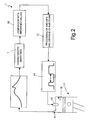
- FIG. 2 Designated, as a whole, by 1 in Figure 2 is a closed-loop electronic control system for controlling combustion in a diesel engine operating with highly premixed combustion.
- the system 1 comprises a plurality of sensors 5 (of a known type) which are designed for measuring and/or calculating some quantities characteristic of the process of fuel combustion, for example the instant of start of combustion, the centroid of the process of combustion, the maximum derivative of the pressure cycle, the noise emitted during the combustion cycle, etc.
- the sensors 5 may be physical sensors designed for measuring directly said quantities or else virtual sensors designed for extrapolating the quantities by means of mathematical calculations based upon different input data. For example, in the absence of a specific sensor of combustion noise, said quantity can be measured starting from the pressure signal indicating the pressure inside the cylinder, calculating its derivative as a function of the engine angle and exploiting the direct proportionality that exists between combustion noise and maximum derivative of the pressure cycle.
- the sensors 5 produce output signals which, after being treated by a processing block 7, are compared with reference values in a comparison block 10, which generates error signals that are supplied at input to a control block 12, which then performs a closed-loop control, based upon the input error signals, of the modalities of fuel injection.
- the block 12 acts on an injection system 14 that controls injectors 15 used for fuel supply to the combustion chambers 16 of a diesel engine 17 (illustrated schematically).
- the injection system 14 is preferably of the common-rail type and is able to inject into the combustion chamber 16 of each cylinder two or more injections of fuel per engine cycle.
- the injection system 14 is designed to obtain ( Figure 3 ) at least one first injection or pilot injection P, with which there is supplied a reduced amount of fuel Qp, followed in time by a second injection or main injection M, with which a larger amount of fuel Qm is supplied.
- the control system acts so as to cause the quantities measured to converge to the respective reference values.
- At least one of the following parameters is regulated:
- the amount of fuel Qp injected by means of the pilot injection P can, for example, be regulated by carrying out a pre-set number of successive cycles of opening of the injector. It is clear how the amount of fuel Qp injected increases as the number of cycles of opening of the injector increases.
- the amount of fuel Qm supplied with the main injection M is varied accordingly for the purpose of maintaining the amount of fuel (Qp+Qm) totally injected by means of the two subsequent injections P, M constant.
- the amount of fuel Qp injected with the pilot injection P increases, the amount of fuel Qm injected with the main injection M decreases, and vice versa.
- Figure 4a shows the plot of the peak value of the heat release or heat-release rate (HRR), i.e., the maximum peak of curve C, as a function of the distance Tp-m; as may be noted, as the distance Tp-m increases, there is a monotonic reduction in the peak value of the HRR.
- HRR heat release or heat-release rate
- Figure 4b shows the trend of the angular position of the centroid of combustion as a function of the distance Tp-m; as may be noted, as the distance Tp-m increases, the centroid of combustion shifts in time towards smaller time values with respect to a reference value consisting of the top dead centre TDC (the position of the TDC may be identified along the axis Y). Likewise, as the distance Tp-m is reduced, the centroid of combustion shifts in time towards higher time values with respect to a reference value consisting of the TDC.
- the reduction in the heat-release peak ( Figure 4a ) entails a reduction in the pressure gradient and consequently produces a reduction in the combustion noise ( Figure 4c ), which decreases as Tp-m increases, until a minimum is reached, after which the noise starts to increase again.
- a further increase in the distance between the injections concurs to increasing the combustion noise since the source of noise becomes the pilot combustion.
- the pilot injection P must anyway supply a large amount of fuel in such a way that the variation of the distance in time Tp-m is able to modify markedly the centroid of combustion.
- the system can therefore increase the distance in time Tp-m for the purpose of anticipating the centroid of combustion ( Figure 4b , arrow F1).
- the control proceeds by bringing the pilot injection P closer to the main injection M ( Figure 4b , arrow F2).
- Said approach can be carried out up to a limit value, which is a parameter characteristic of the injection system, beyond which any further approach is no longer possible.
- the system shifts in time both the pilot injection P and the main injection M with respect to a reference (TDC), in the direction consistent with the required displacement of centroid.
- the two control strategies can be used individually or else simultaneously, thus summing the contributions that can be obtained from the individual strategies.
- both of the strategies a) and b) enable displacement of the centroid of combustion.
- the centroid of combustion is displaced towards smaller time values as Tp-m increases or as the fuel injected with the pilot injection P increases. This fact concurs to increasing the overall stability of combustion and is particularly advantageous should there be set up a condition of instability in the combustion itself.
- a condition of instability can for example arise should there occur a long ignition delay and/or a large amount of recirculated burnt gases be supplied to the combustion chamber 16.
- a sudden increase in EGR can in fact further increase the ignition delay, so causing a misfire.
- said conditions of instability can be detected and promptly countered by activating the control that shifts the centroid of combustion.
- the above fact imposes the need for the ignition delays to be longer than the injection times and would appear to be in marked contrast with the use of a pilot injection P.
- the pilot injection P is used for reducing ignition delays and limiting the accumulation of fuel and the step of premixing of the main injection M.
- the pilot injection P is used in an innovative manner and with functions different from those of traditional use in so far as it is executed in such a way as not to vary the ignition delay and the step of premixing of the main injection.
- the pilot injection P is carried out immediately prior to the main injection and in the presence of conditions of low ignitibility in the chamber. In this way, the two injections are completely premixed prior to burning, and the pilot injection P is unable to have any effect on the main injection M, since there is an excessive dispersion of the main injection in the combustion chamber to receive the heat of the pilot injection P.
- pilot injection P is used in the present invention, in the operation with PCCI combustion, with the purpose of providing a tool on which it is possible to act for modifying the form of the release of energy of combustion, and not as a tool for controlling ignition delay of the main injection M.
Claims (15)
- Système d'injection de carburant à commande électronique (14) pour l'utilisation avec un moteur diesel (17) à allumage par compression de charge prémélangée (PCCI) configuré pour effectuer au moins deux injections de carburant diesel dans un cylindre par cycle de moteur, les injections de carburant diesel comprenant au moins une injection de carburant pilote (P), qui est la première injection de carburant dans le cycle de moteur, et une injection de carburant principale successive (M) ; le système d'injection de carburant à commande électronique (14) comprenant un système de régulation électronique à boucle fermée (1) comprenant :des moyens de capteur (5) configurés pour mesurer ou calculer des quantités caractéristiques du processus de combustion de carburant dans un cycle de moteur et comprenant au moins les quantités suivantes :- un centroïde de combustion ;- un bruit de combustion ; et- une dérivée de pression maximale ; etdes moyens de régulation électronique à boucle fermée (12) configurés pour commander l'injection de carburant sur la base des quantités mesurées ou calculées et de valeurs de référence ;
caractérisé en ce que les moyens de régulation électronique à boucle fermée (12) sont configurés pour réguler :- une longueur de temps (Tp-m) entre l'injection de carburant pilote (P) et l'injection de carburant principale (M) pour contrôler au moins un parmi le centroïde de combustion, le bruit de combustion et la dérivée de pression maximale ; et- une quantité (Qp) de carburant injecté durant l'injection de carburant pilote (P) pour contrôler le centroïde de combustion. - Système d'injection de carburant selon la revendication 1, dans lequel les moyens de régulation électronique à boucle fermée (12) sont configurés pour réguler la longueur de temps (Tp-m) entre l'injection de carburant pilote (P) et l'injection de carburant principale (M) en maintenant constante la position dans le temps de l'injection principale (M) et en régulant dans le temps la position de l'injection pilote (P).
- Système d'injection de carburant selon la revendication 1, dans lequel les moyens de régulation électronique à boucle fermée (12) sont configurés pour maintenir sensiblement constante la quantité totale (Qp+Qm) de carburant injecté durant les injections de carburant pilote et principale (P, M).
- Système d'injection de carburant selon la revendication 1, dans lequel les moyens de régulation électronique à boucle fermée (12) sont configurés pour réguler la quantité (Qp) de carburant injecté durant l'injection de carburant pilote (P) en ouvrant un injecteur (15) un nombre de fois prédéterminé.
- Système d'injection de carburant selon la revendication 1, dans lequel les moyens de régulation électronique à boucle fermée (12) sont configurés pour contrôler la stabilité de combustion de manière à détecter toute instabilité éventuelle et activer en conséquence la commande d'injection de carburant, qui concourt à anticiper le centroïde de combustion en s'opposant ainsi à l'instabilité.
- Système d'injection de carburant selon la revendication 1, dans lequel les moyens de régulation électronique à boucle fermée (12) sont configurés pour contrôler la position du centroïde de combustion au moyen d'une ou plusieurs des opérations suivantes :- déplacer dans le temps l'injection de carburant pilote (P) et l'injection de carburant principale (M) pour obtenir un positionnement grossier du centroïde de combustion ;- réguler la longueur de temps (Tp-m) entre l'injection de carburant pilote (P) et l'injection de carburant principale (M) pour obtenir un positionnement précis du centroïde de combustion ; et- réguler la quantité (Qp) de carburant injecté durant l'injection de carburant pilote (P).
- Système d'injection de carburant selon la revendication 6, dans lequel les moyens de régulation électronique à boucle fermée (12) sont configurés pour augmenter la longueur de temps (Tp-m) entre l'injection de carburant pilote (P) et l'injection de carburant principale (M) de manière à anticiper le centroïde de combustion.
- Système d'injection de carburant selon la revendication 6, dans lequel les moyens de régulation électronique à boucle fermée (12) sont configurés pour augmenter la quantité (Qp) de carburant injecté durant l'injection de carburant pilote (P) de manière à anticiper le centroïde de combustion.
- Système d'injection de carburant selon la revendication 6, dans lequel les moyens de régulation électronique à boucle fermée (12) sont configurés pour réguler la quantité (Qp) de carburant injecté durant l'injection de carburant pilote (P) de manière à maintenir sensiblement constante la quantité totale (Qp+Qm) de carburant injecté durant les injections de carburant pilote et principale (P, M).
- Système d'injection de carburant selon la revendication 1, dans lequel les moyens de régulation électronique à boucle fermée (12) sont configurés pour réguler la longueur de temps (Tp-m) entre l'injection de carburant pilote (P) et l'injection de carburant principale (M) de manière à affecter le bruit de combustion.
- Système d'injection de carburant selon la revendication 1, dans lequel les moyens de régulation électronique à boucle fermée (12) sont configurés pour augmenter la longueur de temps (Tp-m) entre l'injection de carburant pilote (P) et l'injection de carburant principale (M) de manière à réduire le bruit de combustion.
- Système d'injection de carburant selon la revendication 6 ou 11, dans lequel les moyens de régulation électronique à boucle fermée (12) sont configurés pour augmenter la longueur de temps (Tp-m) entre l'injection de carburant pilote (P) et l'injection de carburant principale (M) jusqu'à une valeur limite (Tmax), au-delà de laquelle une augmentation ultérieure de la longueur entraîne une augmentation du bruit de combustion.
- Système d'injection de carburant selon la revendication 12, dans lequel les moyens de régulation électronique à boucle fermée (12) sont configurés pour décaler dans le temps à la fois l'injection de carburant pilote (P) et l'injection de carburant principale (M) de manière à décaler ultérieurement le centroïde de combustion sans augmenter le bruit de combustion, quand la valeur limite (Tmax) est atteinte et en même temps une anticipation ultérieure du centroïde de combustion est nécessaire.
- Système d'injection de carburant selon la revendication 1, dans lequel la quantité (Qm) de carburant injecté durant l'injection de carburant principale (M) est une fonction de la vitesse et de la charge du moteur (RPM, BMEP).
- Moteur diesel (17) à allumage par compression de charge prémélangée (PCCI) équipé d'un système d'injection de carburant à commande électronique (14) selon l'une quelconque des revendications précédentes.
Priority Applications (6)
| Application Number | Priority Date | Filing Date | Title |
|---|---|---|---|
| EP04425444A EP1607609B1 (fr) | 2004-06-15 | 2004-06-15 | Système de régulation pour contrôler la combustion dans un moteur diesel fonctionnant avec combustion prémélangée |
| DE602004020197T DE602004020197D1 (de) | 2004-06-15 | 2004-06-15 | Regelungssystem zur Regelung der Verbrennung in einem Dieselmotor mit vorgemischter Verbrennung |
| AT04425444T ATE426739T1 (de) | 2004-06-15 | 2004-06-15 | Regelungssystem zur regelung der verbrennung in einem dieselmotor mit vorgemischter verbrennung |
| US11/106,463 US7497199B2 (en) | 2004-06-15 | 2005-04-15 | Closed-loop electronic control system for controlling combustion in a diesel engine operating with highly premixed combustion |
| JP2005131241A JP4546872B2 (ja) | 2004-06-15 | 2005-04-28 | 高予混燃焼で操業するディーゼルエンジンの燃焼制御用閉ループ電子制御システム |
| JP2009147439A JP2009209943A (ja) | 2004-06-15 | 2009-06-22 | 高予混燃焼で操業するディーゼルエンジンの燃焼制御用閉ループ電子制御システム |
Applications Claiming Priority (1)
| Application Number | Priority Date | Filing Date | Title |
|---|---|---|---|
| EP04425444A EP1607609B1 (fr) | 2004-06-15 | 2004-06-15 | Système de régulation pour contrôler la combustion dans un moteur diesel fonctionnant avec combustion prémélangée |
Publications (2)
| Publication Number | Publication Date |
|---|---|
| EP1607609A1 EP1607609A1 (fr) | 2005-12-21 |
| EP1607609B1 true EP1607609B1 (fr) | 2009-03-25 |
Family
ID=34932566
Family Applications (1)
| Application Number | Title | Priority Date | Filing Date |
|---|---|---|---|
| EP04425444A Not-in-force EP1607609B1 (fr) | 2004-06-15 | 2004-06-15 | Système de régulation pour contrôler la combustion dans un moteur diesel fonctionnant avec combustion prémélangée |
Country Status (5)
| Country | Link |
|---|---|
| US (1) | US7497199B2 (fr) |
| EP (1) | EP1607609B1 (fr) |
| JP (2) | JP4546872B2 (fr) |
| AT (1) | ATE426739T1 (fr) |
| DE (1) | DE602004020197D1 (fr) |
Cited By (1)
| Publication number | Priority date | Publication date | Assignee | Title |
|---|---|---|---|---|
| FR3085723A1 (fr) | 2018-09-07 | 2020-03-13 | Renault S.A.S | Procede de regulation de la combustion dans un moteur diesel a combustion homogene ou quasi-homogene |
Families Citing this family (42)
| Publication number | Priority date | Publication date | Assignee | Title |
|---|---|---|---|---|
| JP2006177241A (ja) * | 2004-12-22 | 2006-07-06 | Nissan Motor Co Ltd | 内燃機関の制御装置 |
| DE102006019317A1 (de) * | 2005-07-14 | 2007-01-25 | Robert Bosch Gmbh | Zur Dosierung von Kraftstoff zu Brennräumen eines Verbrennungsmotors dienendes Verfahren und Steuergerät |
| US7334562B2 (en) * | 2005-10-24 | 2008-02-26 | Ford Global Technologies Llc | Homogenous charge compression ignition engine control |
| DE102005058820B4 (de) | 2005-12-09 | 2016-11-17 | Daimler Ag | Verfahren zur Regelung einer Brennkraftmaschine, insbesondere einer selbstzündenden Brennkraftmaschine |
| DE102005059908A1 (de) * | 2005-12-15 | 2007-06-28 | Robert Bosch Gmbh | Verfahren zur Dosierung von Kraftstoff in Brennräume eines Verbrennungsmotors |
| FR2904043A3 (fr) * | 2006-07-21 | 2008-01-25 | Renault Sas | Procede d'amelioration du diagnostic d'une vanne de recirculation d'un gaz recircule dans un moteur. |
| EP1903204A1 (fr) | 2006-09-12 | 2008-03-26 | Siemens Aktiengesellschaft | Procédé pour la réduction des émissions de polluants et de la consommation d'un moteur |
| DE102006044866B4 (de) * | 2006-09-22 | 2008-11-20 | Continental Automotive Gmbh | Verfahren und Vorrichtung zur Erzeugung von Einspritzsignalen für ein Einspritzsystem eines Verbrennungsmotors |
| FR2908462B1 (fr) * | 2006-11-15 | 2011-12-09 | Renault Sas | Systeme et procede de commande d'un moteur a combustion interne |
| DE102008000916B4 (de) * | 2007-04-02 | 2021-12-16 | Denso Corporation | Verbrennungssteuerungsvorrichtung für direkt einspritzende Kompressionszündungskraftmaschine |
| DE102007027483A1 (de) * | 2007-06-14 | 2008-12-18 | Robert Bosch Gmbh | Verfahren zur Ermittlung eines Qualitätsmerkmals eines Dieselkraftstoffes |
| FR2918117B1 (fr) * | 2007-06-27 | 2009-07-31 | Renault Sas | Procede et dispositif de commande d'injections d'un moteur, vehicule automobile muni du dispositif. |
| DE102007033469B4 (de) * | 2007-07-18 | 2017-06-14 | Continental Automotive Gmbh | Verfahren und Vorrichtung zur Formung eines elektrischen Steuersignals für einen Einspritzimpuls |
| US7740000B2 (en) * | 2007-12-14 | 2010-06-22 | Gm Global Technology Operations, Inc. | Method and apparatus for injecting fuel into a compression-ignition engine |
| EP2075442B1 (fr) | 2007-12-31 | 2012-09-05 | C.R.F. Società Consortile per Azioni | Système de contrôle de combustion électronique en boucle fermée pour moteur diesel fonctionnant avec un allumage de compression de charge prémélangée |
| FR2929649A1 (fr) * | 2008-04-03 | 2009-10-09 | Renault Sas | Systeme et procede de controle de la stabilite des combustions survenant dans un moteur a combustion interne |
| JP5086887B2 (ja) * | 2008-05-16 | 2012-11-28 | トヨタ自動車株式会社 | 内燃機関の燃料噴射制御装置 |
| JP4625111B2 (ja) * | 2008-05-19 | 2011-02-02 | 本田技研工業株式会社 | 内燃機関の燃料制御装置 |
| WO2009143858A1 (fr) * | 2008-05-26 | 2009-12-03 | Fev Motorentechnik Gmbh | Procédé de régulation d'une opération d'injection dans un moteur à combustion interne, appareil de commande pour moteur à combustion interne et moteur à combustion interne |
| EP2447517B1 (fr) * | 2009-10-21 | 2018-09-05 | Toyota Jidosha Kabushiki Kaisha | Dispositif de commande de combustion pour moteur à combustion interne |
| GB2477538B (en) * | 2010-02-05 | 2017-04-19 | Gm Global Tech Operations Llc | Method for operating an injection system of an internal combustion engine |
| EP2383454A1 (fr) * | 2010-04-27 | 2011-11-02 | C.R.F. Società Consortile per Azioni | Formage du débit d'injection de carburant dans un moteur à combustion interne |
| JP5482715B2 (ja) * | 2010-06-30 | 2014-05-07 | マツダ株式会社 | ディーゼルエンジン及びディーゼルエンジンの制御方法 |
| JP5062340B2 (ja) | 2011-03-11 | 2012-10-31 | 株式会社豊田自動織機 | 燃料噴射装置 |
| JP5675466B2 (ja) * | 2011-03-31 | 2015-02-25 | 三菱重工業株式会社 | エンジンの燃焼診断信号異常時のパイロット噴射タイミング制御方法および装置 |
| US9670851B2 (en) * | 2011-04-28 | 2017-06-06 | International Engine Intellectual Property Company, Llc | System and method of controlling combustion in an engine having an in-cylinder pressure sensor |
| CN102493885A (zh) * | 2011-12-14 | 2012-06-13 | 中国人民解放军装甲兵工程学院 | 柴油机燃烧闭环控制的电控系统 |
| DE102012004585A1 (de) * | 2012-03-09 | 2013-09-12 | Man Truck & Bus Ag | Schallabstrahlreduziertes Kraftfahrzeug |
| EP2725215A1 (fr) * | 2012-10-23 | 2014-04-30 | Delphi International Operations Luxembourg S.à r.l. | Procédé de fonctionnement d'un moteur à combustion interne |
| CA2798599C (fr) * | 2012-12-14 | 2013-11-12 | Westport Power Inc. | Systeme d'injection a ouverture variable des soupapes et sa methode |
| CN105264207B (zh) | 2013-06-05 | 2018-05-29 | 丰田自动车株式会社 | 内燃机的控制装置 |
| CN105264210B (zh) | 2013-06-05 | 2019-06-25 | 丰田自动车株式会社 | 内燃机的控制装置 |
| JP5950041B2 (ja) | 2013-06-10 | 2016-07-13 | トヨタ自動車株式会社 | 機関制御装置 |
| JP6160395B2 (ja) * | 2013-09-20 | 2017-07-12 | トヨタ自動車株式会社 | 内燃機関の制御装置 |
| JP5873059B2 (ja) * | 2013-09-30 | 2016-03-01 | 株式会社豊田中央研究所 | 圧縮着火式内燃機関 |
| JP6866754B2 (ja) | 2016-05-17 | 2021-04-28 | トヨタ自動車株式会社 | 圧縮着火式内燃機関の制御装置 |
| JP2018100623A (ja) * | 2016-12-20 | 2018-06-28 | いすゞ自動車株式会社 | 内燃機関の燃料噴射装置及びプレ噴射制御方法 |
| JP6508186B2 (ja) * | 2016-12-22 | 2019-05-08 | トヨタ自動車株式会社 | 内燃機関の制御装置 |
| JP6787140B2 (ja) | 2017-01-12 | 2020-11-18 | トヨタ自動車株式会社 | 内燃機関の制御装置 |
| SE541367C2 (en) * | 2017-08-31 | 2019-08-27 | Scania Cv Ab | Method and system for determining in-cycle a pilot injection fuel mass in a combustion chamber of an engine |
| JP6583380B2 (ja) * | 2017-10-12 | 2019-10-02 | マツダ株式会社 | ディーゼルエンジンの制御装置及び制御方法 |
| DE102021205361A1 (de) * | 2021-05-26 | 2022-12-01 | Rolls-Royce Solutions GmbH | Verfahren zum Betreiben einer Brennkraftmaschine und Brennkraftmaschine, eingerichtet zur Durchführung eines solchen Verfahrens |
Citations (1)
| Publication number | Priority date | Publication date | Assignee | Title |
|---|---|---|---|---|
| JP2001123871A (ja) * | 1999-10-22 | 2001-05-08 | Nissan Motor Co Ltd | ディーゼルエンジンの制御装置 |
Family Cites Families (30)
| Publication number | Priority date | Publication date | Assignee | Title |
|---|---|---|---|---|
| DE3428371A1 (de) * | 1984-08-01 | 1986-02-13 | Robert Bosch Gmbh, 7000 Stuttgart | Verfahren zur messung und regelung von betriebsdaten von verbrennungsmotoren |
| JPH086627B2 (ja) * | 1985-06-04 | 1996-01-29 | 株式会社日本自動車部品総合研究所 | ディーゼルエンジンの燃料噴射制御方法及び制御装置 |
| US4796577A (en) * | 1986-06-16 | 1989-01-10 | Baranescu George S | Injection system with pilot injection |
| US5119780A (en) * | 1991-06-11 | 1992-06-09 | Southwest Research Institute | Staged direct injection diesel engine |
| AU4158097A (en) | 1996-08-23 | 1998-03-06 | Cummins Engine Company Inc. | Premixed charge compression ignition engine with optimal combustion control |
| US5875743A (en) * | 1997-07-28 | 1999-03-02 | Southwest Research Institute | Apparatus and method for reducing emissions in a dual combustion mode diesel engine |
| JP3092552B2 (ja) * | 1997-09-16 | 2000-09-25 | トヨタ自動車株式会社 | 圧縮着火式内燃機関 |
| JP3622446B2 (ja) * | 1997-09-30 | 2005-02-23 | 日産自動車株式会社 | ディーゼルエンジンの燃焼制御装置 |
| JPH11173200A (ja) | 1997-12-08 | 1999-06-29 | Toyota Motor Corp | 内燃機関の燃料噴射制御装置 |
| CN1292153C (zh) * | 1998-02-23 | 2006-12-27 | 卡明斯发动机公司 | 带有优化燃烧控制的预混合充量压缩点火发动机 |
| JP3873431B2 (ja) * | 1998-03-03 | 2007-01-24 | 日産自動車株式会社 | ディーゼルエンジンの制御装置 |
| JP2000130200A (ja) | 1998-10-30 | 2000-05-09 | Mitsubishi Motors Corp | ディーゼルエンジンの制御装置 |
| US6640773B2 (en) * | 2000-12-26 | 2003-11-04 | Westport Research Inc. | Method and apparatus for gaseous fuel introduction and controlling combustion in an internal combustion engine |
| WO2001059285A2 (fr) * | 2000-02-11 | 2001-08-16 | Westport Research Inc. | Procede et appareil permettant d'introduire du carburant gazeux et de reguler la combustion dans un moteur a combustion interne |
| DE10191820B4 (de) * | 2000-05-08 | 2009-04-02 | Cummins, Inc., Columbus | Verbrennungsmotor betreibbar in einem PCCI-Modus mit früher Steuereinspritzung und Betriebsverfahren. |
| US6705277B1 (en) * | 2000-07-13 | 2004-03-16 | Caterpillar Inc | Method and apparatus for delivering multiple fuel injections to the cylinder of an engine wherein the pilot fuel injection occurs during the intake stroke |
| DE10064505A1 (de) * | 2000-12-22 | 2002-07-04 | Bosch Gmbh Robert | Verfahren und Vorrichtung zur Überwachung eines Abstands zwischen zwei Einspritzvorgängen |
| US6912992B2 (en) * | 2000-12-26 | 2005-07-05 | Cummins Westport Inc. | Method and apparatus for pilot fuel introduction and controlling combustion in gaseous-fuelled internal combustion engine |
| JP3912027B2 (ja) * | 2001-04-26 | 2007-05-09 | 日産自動車株式会社 | 自己着火式内燃機関 |
| AT5217U1 (de) * | 2001-09-28 | 2002-04-25 | Avl List Gmbh | Verfahren zum geregelten betrieb einer brennkraftmaschine |
| US20030150420A1 (en) * | 2001-10-12 | 2003-08-14 | Naoya Ishikawa | Compression-ignition internal combustion engine |
| JP4122803B2 (ja) * | 2002-03-12 | 2008-07-23 | トヨタ自動車株式会社 | ディーゼルエンジンの燃料噴射制御装置 |
| US6964256B2 (en) * | 2002-03-28 | 2005-11-15 | Mazda Motor Corporation | Combustion control apparatus for an engine |
| DE10221001A1 (de) | 2002-05-11 | 2003-11-27 | Daimler Chrysler Ag | Verfahren und Vorrichtung zur Bestimmung einer Voreinspritzmenge |
| JP3966096B2 (ja) * | 2002-06-20 | 2007-08-29 | 株式会社デンソー | 内燃機関用噴射量制御装置 |
| ES2430164T3 (es) * | 2002-09-09 | 2013-11-19 | Toyota Jidosha Kabushiki Kaisha | Dispositivo de control para un motor de combustión interna |
| JP4075588B2 (ja) * | 2002-11-26 | 2008-04-16 | いすゞ自動車株式会社 | ディーゼルエンジン |
| JP4472932B2 (ja) * | 2003-02-07 | 2010-06-02 | いすゞ自動車株式会社 | エンジンの燃焼制御装置 |
| US6966040B2 (en) * | 2003-03-14 | 2005-11-15 | Combustion Dynamics Corp. | Systems and methods for operating an electromagnetic actuator |
| US7000596B2 (en) * | 2003-10-03 | 2006-02-21 | Cummins Westport Inc. | Method and apparatus for controlling an internal combustion engine using combustion chamber pressure sensing |
-
2004
- 2004-06-15 EP EP04425444A patent/EP1607609B1/fr not_active Not-in-force
- 2004-06-15 DE DE602004020197T patent/DE602004020197D1/de active Active
- 2004-06-15 AT AT04425444T patent/ATE426739T1/de not_active IP Right Cessation
-
2005
- 2005-04-15 US US11/106,463 patent/US7497199B2/en not_active Expired - Fee Related
- 2005-04-28 JP JP2005131241A patent/JP4546872B2/ja not_active Expired - Fee Related
-
2009
- 2009-06-22 JP JP2009147439A patent/JP2009209943A/ja active Pending
Patent Citations (1)
| Publication number | Priority date | Publication date | Assignee | Title |
|---|---|---|---|---|
| JP2001123871A (ja) * | 1999-10-22 | 2001-05-08 | Nissan Motor Co Ltd | ディーゼルエンジンの制御装置 |
Non-Patent Citations (1)
| Title |
|---|
| "Automotive Handbook", 1996, ROBERT BOSCH GMBH, GERMANY * |
Cited By (1)
| Publication number | Priority date | Publication date | Assignee | Title |
|---|---|---|---|---|
| FR3085723A1 (fr) | 2018-09-07 | 2020-03-13 | Renault S.A.S | Procede de regulation de la combustion dans un moteur diesel a combustion homogene ou quasi-homogene |
Also Published As
| Publication number | Publication date |
|---|---|
| JP2006002760A (ja) | 2006-01-05 |
| JP4546872B2 (ja) | 2010-09-22 |
| US7497199B2 (en) | 2009-03-03 |
| DE602004020197D1 (de) | 2009-05-07 |
| EP1607609A1 (fr) | 2005-12-21 |
| ATE426739T1 (de) | 2009-04-15 |
| US20050274352A1 (en) | 2005-12-15 |
| JP2009209943A (ja) | 2009-09-17 |
Similar Documents
| Publication | Publication Date | Title |
|---|---|---|
| EP1607609B1 (fr) | Système de régulation pour contrôler la combustion dans un moteur diesel fonctionnant avec combustion prémélangée | |
| US5875743A (en) | Apparatus and method for reducing emissions in a dual combustion mode diesel engine | |
| CN101160458B (zh) | 用于在具有受控自燃燃烧的直喷发动机的稀空燃比和化学计量空燃比燃烧模式之间负载转变控制的方法 | |
| US7334561B2 (en) | Internal combustion engine | |
| EP2075442B1 (fr) | Système de contrôle de combustion électronique en boucle fermée pour moteur diesel fonctionnant avec un allumage de compression de charge prémélangée | |
| US20110056459A1 (en) | Fuel injection control apparatus for internal combustion engine | |
| JP5998705B2 (ja) | 圧縮自己着火式エンジン | |
| JP6787140B2 (ja) | 内燃機関の制御装置 | |
| US9845761B2 (en) | Fuel estimation apparatus | |
| EP0937883B1 (fr) | Méthode de contrôle de l'injection dans un moteur à auto-allumage | |
| JP2018091267A (ja) | 内燃機関の制御装置 | |
| JP6508186B2 (ja) | 内燃機関の制御装置 | |
| EP2392808A1 (fr) | Dispositif de commande pour moteur à combustion interne | |
| US20190093592A1 (en) | Combustion control device for compression autoignition engine | |
| US20150114355A1 (en) | Method and apparatus for controlling combustion of engine having mixed combustion mode | |
| US20160363074A1 (en) | Combustion system controller | |
| US20170234257A1 (en) | Gdci transient egr error compensation | |
| WO2012176746A1 (fr) | Dispositif de commande pour moteur à combustion interne du type à injection dans un cylindre | |
| JP6477619B2 (ja) | 内燃機関の制御装置 | |
| US9175612B2 (en) | Method and apparatus for controlling combustion of engine having mixed combustion mode | |
| WO2013054434A1 (fr) | Dispositif de commande pour moteur à combustion interne | |
| JP3823740B2 (ja) | 予混合圧縮自己着火式エンジンの制御装置 | |
| WO2013038805A1 (fr) | Dispositif de commande de combustion | |
| EP3246552B1 (fr) | Système de commande d'un moteur à combustion interne de type à allumage par compression | |
| JP2009293596A (ja) | 内燃機関の燃料噴射制御装置 |
Legal Events
| Date | Code | Title | Description |
|---|---|---|---|
| PUAI | Public reference made under article 153(3) epc to a published international application that has entered the european phase |
Free format text: ORIGINAL CODE: 0009012 |
|
| 17P | Request for examination filed |
Effective date: 20041230 |
|
| AK | Designated contracting states |
Kind code of ref document: A1 Designated state(s): AT BE BG CH CY CZ DE DK EE ES FI FR GB GR HU IE IT LI LU MC NL PL PT RO SE SI SK TR |
|
| AX | Request for extension of the european patent |
Extension state: AL HR LT LV MK |
|
| AKX | Designation fees paid |
Designated state(s): AT BE BG CH CY CZ DE DK EE ES FI FR GB GR HU IE IT LI LU MC NL PL PT RO SE SI SK TR |
|
| 17Q | First examination report despatched |
Effective date: 20050428 |
|
| GRAP | Despatch of communication of intention to grant a patent |
Free format text: ORIGINAL CODE: EPIDOSNIGR1 |
|
| GRAS | Grant fee paid |
Free format text: ORIGINAL CODE: EPIDOSNIGR3 |
|
| GRAA | (expected) grant |
Free format text: ORIGINAL CODE: 0009210 |
|
| RIN1 | Information on inventor provided before grant (corrected) |
Inventor name: PELASSA, MICHELE,C/O C.R.F. SOCIETA CONSORTILE PER Inventor name: CANALE, SILVIO,C/O C.R.F. SOCIETA CONSORTILE PER A |
|
| AK | Designated contracting states |
Kind code of ref document: B1 Designated state(s): AT BE BG CH CY CZ DE DK EE ES FI FR GB GR HU IE IT LI LU MC NL PL PT RO SE SI SK TR |
|
| REG | Reference to a national code |
Ref country code: GB Ref legal event code: FG4D |
|
| REG | Reference to a national code |
Ref country code: CH Ref legal event code: EP |
|
| REG | Reference to a national code |
Ref country code: IE Ref legal event code: FG4D |
|
| REF | Corresponds to: |
Ref document number: 602004020197 Country of ref document: DE Date of ref document: 20090507 Kind code of ref document: P |
|
| PG25 | Lapsed in a contracting state [announced via postgrant information from national office to epo] |
Ref country code: FI Free format text: LAPSE BECAUSE OF FAILURE TO SUBMIT A TRANSLATION OF THE DESCRIPTION OR TO PAY THE FEE WITHIN THE PRESCRIBED TIME-LIMIT Effective date: 20090325 Ref country code: SI Free format text: LAPSE BECAUSE OF FAILURE TO SUBMIT A TRANSLATION OF THE DESCRIPTION OR TO PAY THE FEE WITHIN THE PRESCRIBED TIME-LIMIT Effective date: 20090325 |
|
| PG25 | Lapsed in a contracting state [announced via postgrant information from national office to epo] |
Ref country code: AT Free format text: LAPSE BECAUSE OF FAILURE TO SUBMIT A TRANSLATION OF THE DESCRIPTION OR TO PAY THE FEE WITHIN THE PRESCRIBED TIME-LIMIT Effective date: 20090325 Ref country code: PL Free format text: LAPSE BECAUSE OF FAILURE TO SUBMIT A TRANSLATION OF THE DESCRIPTION OR TO PAY THE FEE WITHIN THE PRESCRIBED TIME-LIMIT Effective date: 20090325 Ref country code: SE Free format text: LAPSE BECAUSE OF FAILURE TO SUBMIT A TRANSLATION OF THE DESCRIPTION OR TO PAY THE FEE WITHIN THE PRESCRIBED TIME-LIMIT Effective date: 20090625 |
|
| NLV1 | Nl: lapsed or annulled due to failure to fulfill the requirements of art. 29p and 29m of the patents act | ||
| PG25 | Lapsed in a contracting state [announced via postgrant information from national office to epo] |
Ref country code: BE Free format text: LAPSE BECAUSE OF FAILURE TO SUBMIT A TRANSLATION OF THE DESCRIPTION OR TO PAY THE FEE WITHIN THE PRESCRIBED TIME-LIMIT Effective date: 20090325 |
|
| PG25 | Lapsed in a contracting state [announced via postgrant information from national office to epo] |
Ref country code: CZ Free format text: LAPSE BECAUSE OF FAILURE TO SUBMIT A TRANSLATION OF THE DESCRIPTION OR TO PAY THE FEE WITHIN THE PRESCRIBED TIME-LIMIT Effective date: 20090325 Ref country code: ES Free format text: LAPSE BECAUSE OF FAILURE TO SUBMIT A TRANSLATION OF THE DESCRIPTION OR TO PAY THE FEE WITHIN THE PRESCRIBED TIME-LIMIT Effective date: 20090706 Ref country code: PT Free format text: LAPSE BECAUSE OF FAILURE TO SUBMIT A TRANSLATION OF THE DESCRIPTION OR TO PAY THE FEE WITHIN THE PRESCRIBED TIME-LIMIT Effective date: 20090901 Ref country code: EE Free format text: LAPSE BECAUSE OF FAILURE TO SUBMIT A TRANSLATION OF THE DESCRIPTION OR TO PAY THE FEE WITHIN THE PRESCRIBED TIME-LIMIT Effective date: 20090325 |
|
| PG25 | Lapsed in a contracting state [announced via postgrant information from national office to epo] |
Ref country code: SK Free format text: LAPSE BECAUSE OF FAILURE TO SUBMIT A TRANSLATION OF THE DESCRIPTION OR TO PAY THE FEE WITHIN THE PRESCRIBED TIME-LIMIT Effective date: 20090325 Ref country code: RO Free format text: LAPSE BECAUSE OF FAILURE TO SUBMIT A TRANSLATION OF THE DESCRIPTION OR TO PAY THE FEE WITHIN THE PRESCRIBED TIME-LIMIT Effective date: 20090325 Ref country code: NL Free format text: LAPSE BECAUSE OF FAILURE TO SUBMIT A TRANSLATION OF THE DESCRIPTION OR TO PAY THE FEE WITHIN THE PRESCRIBED TIME-LIMIT Effective date: 20090325 |
|
| PG25 | Lapsed in a contracting state [announced via postgrant information from national office to epo] |
Ref country code: MC Free format text: LAPSE BECAUSE OF NON-PAYMENT OF DUE FEES Effective date: 20090630 Ref country code: BG Free format text: LAPSE BECAUSE OF FAILURE TO SUBMIT A TRANSLATION OF THE DESCRIPTION OR TO PAY THE FEE WITHIN THE PRESCRIBED TIME-LIMIT Effective date: 20090625 Ref country code: DK Free format text: LAPSE BECAUSE OF FAILURE TO SUBMIT A TRANSLATION OF THE DESCRIPTION OR TO PAY THE FEE WITHIN THE PRESCRIBED TIME-LIMIT Effective date: 20090325 |
|
| PLBE | No opposition filed within time limit |
Free format text: ORIGINAL CODE: 0009261 |
|
| REG | Reference to a national code |
Ref country code: CH Ref legal event code: PL |
|
| STAA | Information on the status of an ep patent application or granted ep patent |
Free format text: STATUS: NO OPPOSITION FILED WITHIN TIME LIMIT |
|
| GBPC | Gb: european patent ceased through non-payment of renewal fee |
Effective date: 20090625 |
|
| 26N | No opposition filed |
Effective date: 20091229 |
|
| PG25 | Lapsed in a contracting state [announced via postgrant information from national office to epo] |
Ref country code: LI Free format text: LAPSE BECAUSE OF NON-PAYMENT OF DUE FEES Effective date: 20090630 Ref country code: IE Free format text: LAPSE BECAUSE OF NON-PAYMENT OF DUE FEES Effective date: 20090615 Ref country code: CH Free format text: LAPSE BECAUSE OF NON-PAYMENT OF DUE FEES Effective date: 20090630 |
|
| PG25 | Lapsed in a contracting state [announced via postgrant information from national office to epo] |
Ref country code: GB Free format text: LAPSE BECAUSE OF NON-PAYMENT OF DUE FEES Effective date: 20090625 |
|
| PG25 | Lapsed in a contracting state [announced via postgrant information from national office to epo] |
Ref country code: GR Free format text: LAPSE BECAUSE OF FAILURE TO SUBMIT A TRANSLATION OF THE DESCRIPTION OR TO PAY THE FEE WITHIN THE PRESCRIBED TIME-LIMIT Effective date: 20090626 |
|
| PG25 | Lapsed in a contracting state [announced via postgrant information from national office to epo] |
Ref country code: LU Free format text: LAPSE BECAUSE OF NON-PAYMENT OF DUE FEES Effective date: 20090615 |
|
| PG25 | Lapsed in a contracting state [announced via postgrant information from national office to epo] |
Ref country code: HU Free format text: LAPSE BECAUSE OF FAILURE TO SUBMIT A TRANSLATION OF THE DESCRIPTION OR TO PAY THE FEE WITHIN THE PRESCRIBED TIME-LIMIT Effective date: 20090926 |
|
| PG25 | Lapsed in a contracting state [announced via postgrant information from national office to epo] |
Ref country code: TR Free format text: LAPSE BECAUSE OF FAILURE TO SUBMIT A TRANSLATION OF THE DESCRIPTION OR TO PAY THE FEE WITHIN THE PRESCRIBED TIME-LIMIT Effective date: 20090325 |
|
| PG25 | Lapsed in a contracting state [announced via postgrant information from national office to epo] |
Ref country code: CY Free format text: LAPSE BECAUSE OF FAILURE TO SUBMIT A TRANSLATION OF THE DESCRIPTION OR TO PAY THE FEE WITHIN THE PRESCRIBED TIME-LIMIT Effective date: 20090325 |
|
| REG | Reference to a national code |
Ref country code: FR Ref legal event code: PLFP Year of fee payment: 13 |
|
| REG | Reference to a national code |
Ref country code: FR Ref legal event code: PLFP Year of fee payment: 14 |
|
| REG | Reference to a national code |
Ref country code: FR Ref legal event code: PLFP Year of fee payment: 15 |
|
| PGFP | Annual fee paid to national office [announced via postgrant information from national office to epo] |
Ref country code: FR Payment date: 20180629 Year of fee payment: 15 Ref country code: IT Payment date: 20180611 Year of fee payment: 15 |
|
| PGFP | Annual fee paid to national office [announced via postgrant information from national office to epo] |
Ref country code: DE Payment date: 20180831 Year of fee payment: 15 |
|
| REG | Reference to a national code |
Ref country code: DE Ref legal event code: R119 Ref document number: 602004020197 Country of ref document: DE |
|
| PG25 | Lapsed in a contracting state [announced via postgrant information from national office to epo] |
Ref country code: IT Free format text: LAPSE BECAUSE OF NON-PAYMENT OF DUE FEES Effective date: 20190615 Ref country code: DE Free format text: LAPSE BECAUSE OF NON-PAYMENT OF DUE FEES Effective date: 20200101 |
|
| PG25 | Lapsed in a contracting state [announced via postgrant information from national office to epo] |
Ref country code: FR Free format text: LAPSE BECAUSE OF NON-PAYMENT OF DUE FEES Effective date: 20190630 |