EP0627273A2 - Presswerkzeug - Google Patents
Presswerkzeug Download PDFInfo
- Publication number
- EP0627273A2 EP0627273A2 EP94110654A EP94110654A EP0627273A2 EP 0627273 A2 EP0627273 A2 EP 0627273A2 EP 94110654 A EP94110654 A EP 94110654A EP 94110654 A EP94110654 A EP 94110654A EP 0627273 A2 EP0627273 A2 EP 0627273A2
- Authority
- EP
- European Patent Office
- Prior art keywords
- press
- jaws
- pressing
- tool according
- ring
- Prior art date
- Legal status (The legal status is an assumption and is not a legal conclusion. Google has not performed a legal analysis and makes no representation as to the accuracy of the status listed.)
- Granted
Links
Images
Classifications
-
- B—PERFORMING OPERATIONS; TRANSPORTING
- B21—MECHANICAL METAL-WORKING WITHOUT ESSENTIALLY REMOVING MATERIAL; PUNCHING METAL
- B21D—WORKING OR PROCESSING OF SHEET METAL OR METAL TUBES, RODS OR PROFILES WITHOUT ESSENTIALLY REMOVING MATERIAL; PUNCHING METAL
- B21D39/00—Application of procedures in order to connect objects or parts, e.g. coating with sheet metal otherwise than by plating; Tube expanders
- B21D39/04—Application of procedures in order to connect objects or parts, e.g. coating with sheet metal otherwise than by plating; Tube expanders of tubes with tubes; of tubes with rods
- B21D39/046—Connecting tubes to tube-like fittings
-
- B—PERFORMING OPERATIONS; TRANSPORTING
- B21—MECHANICAL METAL-WORKING WITHOUT ESSENTIALLY REMOVING MATERIAL; PUNCHING METAL
- B21D—WORKING OR PROCESSING OF SHEET METAL OR METAL TUBES, RODS OR PROFILES WITHOUT ESSENTIALLY REMOVING MATERIAL; PUNCHING METAL
- B21D39/00—Application of procedures in order to connect objects or parts, e.g. coating with sheet metal otherwise than by plating; Tube expanders
- B21D39/04—Application of procedures in order to connect objects or parts, e.g. coating with sheet metal otherwise than by plating; Tube expanders of tubes with tubes; of tubes with rods
-
- B—PERFORMING OPERATIONS; TRANSPORTING
- B25—HAND TOOLS; PORTABLE POWER-DRIVEN TOOLS; MANIPULATORS
- B25B—TOOLS OR BENCH DEVICES NOT OTHERWISE PROVIDED FOR, FOR FASTENING, CONNECTING, DISENGAGING OR HOLDING
- B25B27/00—Hand tools, specially adapted for fitting together or separating parts or objects whether or not involving some deformation, not otherwise provided for
- B25B27/02—Hand tools, specially adapted for fitting together or separating parts or objects whether or not involving some deformation, not otherwise provided for for connecting objects by press fit or detaching same
- B25B27/10—Hand tools, specially adapted for fitting together or separating parts or objects whether or not involving some deformation, not otherwise provided for for connecting objects by press fit or detaching same inserting fittings into hoses
-
- B—PERFORMING OPERATIONS; TRANSPORTING
- B25—HAND TOOLS; PORTABLE POWER-DRIVEN TOOLS; MANIPULATORS
- B25B—TOOLS OR BENCH DEVICES NOT OTHERWISE PROVIDED FOR, FOR FASTENING, CONNECTING, DISENGAGING OR HOLDING
- B25B27/00—Hand tools, specially adapted for fitting together or separating parts or objects whether or not involving some deformation, not otherwise provided for
- B25B27/14—Hand tools, specially adapted for fitting together or separating parts or objects whether or not involving some deformation, not otherwise provided for for assembling objects other than by press fit or detaching same
- B25B27/146—Clip clamping hand tools
-
- Y—GENERAL TAGGING OF NEW TECHNOLOGICAL DEVELOPMENTS; GENERAL TAGGING OF CROSS-SECTIONAL TECHNOLOGIES SPANNING OVER SEVERAL SECTIONS OF THE IPC; TECHNICAL SUBJECTS COVERED BY FORMER USPC CROSS-REFERENCE ART COLLECTIONS [XRACs] AND DIGESTS
- Y10—TECHNICAL SUBJECTS COVERED BY FORMER USPC
- Y10T—TECHNICAL SUBJECTS COVERED BY FORMER US CLASSIFICATION
- Y10T29/00—Metal working
- Y10T29/53—Means to assemble or disassemble
- Y10T29/5367—Coupling to conduit
Definitions
- the invention relates to a pressing tool for connecting tubular workpieces with more than two pressing jaws, which can be moved relative to one another with the aid of at least one drive device such that they can be brought into a pressing position from an open position, in which the pressing device can be placed on the workpiece, in which the press jaws complement each other to form a closed press room.
- Coupling sleeves are used to connect pipe ends, which are plastically deformable and made of metal, preferably steel. Their inner diameter is so much larger than the outer diameter of the pipe ends to be connected that they are permanently deformed in the event of radial compression until they rest against the outer surface of the pipe ends. According to DE-PS 11 87 870 ⁇ such coupling sleeves can also have an annular groove on the inside near each end, into which an elastic sealing ring is inserted.
- the radial compression takes place by means of pressing tools, as are known for example from DE-PS 21 36 782.
- This pressing tool has two clamping arms, each with two arms, at least one of which is pivotably mounted on the pressing tool.
- the press jaws have press surfaces which form circular arc sections and have the same radii, which enclose a press space. Instead of being circular arc sections, the pressing surfaces can also be contoured, for example to form a polygonal or oval pressing space.
- the arms of the press jaws located distant from the press chamber can be spread against the action of a spring, with the result that the press jaws are moved against one another in the region of the press chamber.
- the spreading takes place by means of pressure rollers which are arranged next to one another and abut one another and which are moved together between the arms by means of a drive device in the form of a working cylinder and in this way pivot the press jaws.
- this pressing tool is the pressing tool according to the preamble of claim 1 and is described in DE-OS 34 23 283.
- two press jaws are provided which are each pivotably mounted on a drive lever, which in turn are pivotably guided on the press tool.
- the drive levers have opposite arms which can be spread by means of pressure rollers which can be moved into the intermediate space by a working cylinder and in this way move the pressing jaws towards one another.
- the press jaws are additionally guided in scenes such that when the drive levers are pivoted in the opening direction they are pivoted open about their articulation points on the drive levers, so that between the end faces of the press jaws there is a wide, mouth-like opening which accommodates the pipe ends to be connected or a coupling sleeve facilitated.
- the clamping jaws When pivoting the drive lever in the opposite direction, the clamping jaws are pivoted again so that the perpendicular to their arc sections approximately collapse and the jaws are moved parallel to each other when the drive lever is pivoted further. During the pressing process, the clamping jaws are moved further towards one another until they enclose a circular surface at the end of the press and have deformed the pipe ends or the coupling sleeve accordingly with a reduction in diameter.
- This press tool has proven itself when a not too large diameter reduction or insertion depth is required. For larger press-in depths, which are required if the pipe connection is to withstand higher internal pressures, it is necessary to provide more than two press jaws so that there is no formation of outwardly projecting webs between the end faces of the press jaws, which leads to a complete closing of the press jaws would prevent.
- Such pressing tools are described for example in DE-OS 21 18 782, DE-OS 35 13 129, DE-AS 25 11 942 and DE-AS 19 0 ⁇ 7 956. All pressing tools disclosed therein have in common that all pressing jaws are movable and guided in the radial direction. This requires complex guides and drive devices, which makes the pressing tools difficult and therefore difficult to handle and also expensive.
- the invention is therefore based on the object of designing a press tool of the type mentioned in such a way that, despite the arrangement of more than two press jaws, it is as simple as possible and thus easy to handle and can be produced inexpensively.
- press jaws are articulated together to form a press ring, the press ring between two press jaws being open and being closable by means of the drive device (s) by pulling the press ring together.
- This embodiment opens up the possibility that the drive device (s) is or are separate from the press ring and that the drive device (s) and the press ring have coupling elements via which they can be brought into operative connection with one another.
- the press tool is then formed in two parts, the press ring first being placed around the workpiece and then the drive device being attached to the press ring.
- the pressing tool is very advantageous in its handling because the individual parts have a significantly lower weight and can be handled independently of one another.
- the press ring can have at least one tension band lying on the outside against at least the movable press jaws, by means of which the pressure jaws can be moved together, wherein two tension bands can also be provided for this.
- This version is particularly weight and cost-saving.
- the press jaws are of equal length in the circumferential direction, so that the gaps between the respective opposite end faces of the press jaws are uniformly distributed over the circumference.
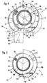
- FIGS. 1 and 2 show two pressing tools 91, 92, half each.
- the pressing tool 91 is shown on the left half of FIGS. 1 and 2 with respect to the axis of symmetry, and the pressing tool 92 is shown on the right half.
- Both pressing tools 91, 92 are mirror-symmetrical, so that their structure results from the representation of their halves.
- the pressing tool 91 shown in the left halves of FIGS. 1 and 2 has a pressing ring 93 which consists of a total of three pressing jaws 94, 95, the pressing jaw 94 only partially and a pressing jaw - namely the right one - not at all due to the half-sided representation are seen.
- a flexible tension band 97 made of spring steel is fastened to the upper press jaw 94 by means of a screw 96 and extends over the circumference of the upper press jaw 94 and the left press jaw 95.
- a corresponding tension band runs to the other side of the press ring 93, not shown here.
- the lower press jaws 95 are guided in the circumferential direction K on the tension bands 97.
- a rubber spring 98 fits into recesses in the opposite end faces of the press jaws 94, 95 and is vulcanized onto them.
- the press jaws 94, 95 are pressed apart by the rubber springs 98 to a certain extent, so that there are gaps 99, 10 ⁇ 0 ⁇ of the same width between the opposite end faces of the press jaws 94, 95 when the press jaws 94, 95 on the outside on a coupling sleeve 10 ⁇ 1 issue.
- coupling attachments 10-2 are attached on the outside.
- a drive device 10 ⁇ 3 shown here only schematically and in dash-dot lines, which is separate from the press ring 93, can be attached to these coupling attachments 10-2.
- the pressing tool 91 thus consists of two independent parts that can be coupled together.
- the drive device 10 ⁇ 3 has two drive levers 10 ⁇ 4, of which only the left one can be seen here. They are rotatably mounted about pivot pins 10 ⁇ 5 extending perpendicular to the plane of the drawing. Your downward-pointing arms 10 ⁇ 6 are spread for pivoting in the direction of arrow L, against the action of a spring, not shown here, which contracts the lower arms 10 ⁇ 6. A pair of pressure rollers is used to spread the arms 10 ⁇ 6, which can be moved into the space between the arms 10 ⁇ 6 with the aid of a pneumatically or hydraulically actuated working cylinder.
- Such a drive device is known per se from DE-PS 21 36 782 and DE-OS 34 23 382.
- the arms 10 ⁇ 7 extending upwards from the pivot bolts 10 ⁇ 5 are shaped in such a way that they can reach behind the coupling projections 10 ⁇ 2.
- the pressing ring 93 When the pressing tool 91 is used, the pressing ring 93 is first opened, so that the lower pressing jaws 95 protrude outwards, as is shown in broken lines. The press ring 93 can then be pushed across the combination of coupling sleeve 10 ⁇ 1 and pipe end 10 ⁇ 8 across its longitudinal axis. Due to the spring action of the drawstrings 97, the press jaws 94, 95 put on the circumference of the coupling sleeve 10-1, and here too only with the outer transverse edges. Then the drive device 10 ⁇ 3 is set in such a way that the upper arms 10 Antriebs7 of the drive lever 10 ⁇ 4 grip the coupling projections 10 ⁇ 2 on the outside, as can be seen from FIG.
- the press tool 92 is functionally similar to the press tool 91. It also has a press ring 10 ⁇ 9, which has three press jaws 110 ⁇ , 111 of the same arc length.
- the upper press jaw 110 ⁇ is firmly arranged on a press jaw support 112, while the two lower press jaws 111 are guided on the press jaw supports 113 so as to be displaceable in the circumferential direction.
- the lower press jaw carriers 113 are articulated to the upper press jaw carrier 112 via swivel joints 114.
- the lower pressing jaws 111 have notches 115 on their outer circumferences, into which pins 116 which are axially displaceably mounted engage in the lower pressing jaw carriers 113. These pins 116 are spring-loaded via compression springs 117 in the direction of the notches 115.
- the pins 116 and the notches 115 are arranged in such a way that the pins 116 endeavor to move the lower pressing jaws 111 against each other in the circumferential direction, that is to say the right lower pressing jaw 111 shown clockwise and the pressing jaw, not shown here, counterclockwise. Stops, not shown here, ensure that the lower press jaws 113 cannot be moved further in these two directions beyond a certain maximum dimension.
- the press tool 92 is handled in the same way as the press tool 91.
- the lower press jaw carriers 113 are brought into contact with the outer circumference of the coupling sleeve 10-1.
- the abovementioned stops for limiting the movement of the lower pressing jaws 111 in the circumferential direction are arranged such that gaps 119, 120 ⁇ between the end faces of the pressing jaws 110 ⁇ , 111 result when the clutch sleeve 10-1 is in contact.
- the pressing tools 91, 92 can also be formed in one piece, i. H. the drive device 10 ⁇ 3 can be connected to one of the press jaws 94, 95 110 ⁇ , 111 via a corresponding housing part.
- the respective press jaw 94, 95, 110 ⁇ , 111 would be comparable to an abutment, the press jaws 94, 95, 110 ⁇ , 111 moving during the pressing process in the direction of the center of the press chamber in the closed state of the press tool 91, 92.
- One of the lower press jaws 95, 111 can also be the press jaw 95, 111 which is arranged in a fixed position on the press tool 91, 92 and performs the function of the abutment. In this case, only one drive lever 10 ⁇ 4 is required to pull the press jaws 94, 95, 110 ⁇ , 111 together.
Landscapes
- Mechanical Engineering (AREA)
- Engineering & Computer Science (AREA)
- Press Drives And Press Lines (AREA)
- Automatic Assembly (AREA)
- Apparatuses For Bulk Treatment Of Fruits And Vegetables And Apparatuses For Preparing Feeds (AREA)
- Perforating, Stamping-Out Or Severing By Means Other Than Cutting (AREA)
- Paper (AREA)
- Measurement Of The Respiration, Hearing Ability, Form, And Blood Characteristics Of Living Organisms (AREA)
- Earth Drilling (AREA)
- Adornments (AREA)
- Infusion, Injection, And Reservoir Apparatuses (AREA)
- Shaping Metal By Deep-Drawing, Or The Like (AREA)
- Mounting, Exchange, And Manufacturing Of Dies (AREA)
Abstract
Description
- Die Erfindung betrifft ein Preßwerkzeug zum Verbinden von rohrförmigen Werkstücken mit mehr als zwei Preßbacken, die mit Hilfe wenigstens einer Antriebseinrichtung derart relativ zueinander bewegbar sind, daß sie aus einer Offenstellung, in der das Preßgerät auf das Werkstück aufsetzbar ist, in eine Preßstellung bringbar sind, in der sich die Preßbacken zu einem geschlossenen Preßraum ergänzen.
- Zur Verbindung von Rohrenden werden Kupplungshülsen verwendet, die plastisch verformbar sind und aus Metall, vorzugsweise aus Stahl bestehen. Ihr Innendurchmesser ist um so viel größer als der Außendurchmesser der zu verbindenden Rohrenden, daß sie bei radialer Zusammenpressung bis zum Anliegen an der Mantelfläche der Rohrenden bleibend verformt werden. Nach der DE-PS 11 87 870̸ können solche Kupplungshülsen an ihrer Innenseite in der Nähe jedes Endes zusätzlich eine Ringnut aufweisen, in die ein elastischer Dichtungsring eingelegt ist.
- Das radiale Zusammenpressen geschieht mittels Preßwerkzeugen, wie sie beispielsweise aus der DE-PS 21 36 782 bekannt sind. Dieses Preßwerkzeug weist zwei jeweils zweiarmig ausgebildete Klemmbacken auf, von denen wenigstens einer schwenkbar an dem Preßwerkzeug gelagert ist. Die Preßbacken weisen Kreisbogenabschnitte bildende Preßflächen mit gleichen Radien auf, die einen Preßraum einschließen. Statt als Kreisbogenabschnitte können die Preßflächen auch konturiert sein, um beispielsweise einen mehreckigen oder ovalen Preßraum zu bilden.
- Die dem Preßraum entfernt liegenden Arme der Preßbacken können gegen die Wirkung einer Feder gespreizt werden mit der Folge, daß die Preßbacken im Bereich des Preßraums gegeneinander bewegt werden. Das Spreizen geschieht mittels nebeneinander angeordneter und aneinander anliegender Druckrollen, die gemeinsam mittels einer Antriebeseinrichtung in Form eines Arbeitszylinders zwischen die Arme gefahren werden und auf diese Weise die Preßbacken verschwenken.
- Eine Weiterentwicklung dieses Preßwerkzeuges stellt das Preßwerkzeug gemäß dem Oberbegriff des Anspruchs 1 dar und ist in der DE-OS 34 23 283 beschrieben. Bei diesem Preßwerkzeug sind zwei Preßbacken vorgesehen, die jeweils an einem Antriebshebel schwenkbar gelagert sind, welche wiederum schwenkbar an dem Preßwerkzeug geführt sind. Die Antriebshebel weisen gegenüberliegende Arme auf, die mittels von einem Arbeitszylinder in den Zwischenraum einfahrbaren Druckrollen gespreizt werden können und auf diese Weise die Preßbacken aufeinanderzu bewegen. Die Preßbacken sind dabei zusätzlich in Kulissen derart geführt, daß sie beim Verschwenken der Antriebshebel in öffnungsrichtung um ihre Anlenkpunkte an den Antriebshebeln aufgeschwenkt werden, so daß zwischen den Stirnseiten der Preßbacken eine weite, maulartige öffnung entsteht, die die Aufnahme der zu verbindenden Rohrenden bzw. einer Kupplungshülse erleichtert.
- Beim Verschwenken der Antriebshebel in umgekehrter Richtung werden die Klemmbacken wieder so verschwenkt, daß die Mittelsenkrechten auf ihre Bogenabschnitte in etwa ineinanderfallen und die Klemmbacken beim weiteren Verschwenken der Antriebshebei parallel gegeneinander verschoben werden. Während des Preßvorgangs werden die Klemmbacken weiter gegeneinander bewegt, bis sie am Preßende eine Kreisfläche einschließen und dabei die Rohrenden bzw. die Kupplungshülse entsprechend unter Durchmesserverringerung verformt haben.
- Dieses Preßwerkzeug hat sich bewährt, wenn eine nicht zu große Durchmesserverkleinerung bzw. Einpreßtiefe gefordert wird. Bei größeren Einpreßtiefen, die dann erforderlich sind, wenn die Rohrverbindung höheren Innendrücken standhalten soll, ist es erforderlich, mehr als zwei Preßbacken vorzusehen, damit es zwischen den Stirnseiten der Preßbacken nicht zum Ausbilden von nach außen vorstehenden Stegen kommt, welche ein vollständiges Schließen der Preßbacken verhindern würden. Solche Preßwerkzeuge sind beispielsweise in der DE-OS 21 18 782, DE-OS 35 13 129, DE-AS 25 11 942 und DE-AS 19 0̸7 956 beschrieben. Allen darin offenbarten Preßwerkzeugen ist gemeinsam, daß sämtliche Preßbacken beweglich und in radialer Richtung geführt sind. Dies bedingt aufwendige Führungen und Antriebseinrichtungen, wodurch die Preßwerkzeuge schwer und deshalb schlecht handhabbar und ferner auch teuer sind.
- Der Erfindung liegt demnach die Aufgabe zugrunde, ein Preßwerkzeug der eingangs genannten Art so zu gestalten, daß es trotz der Anordnung von mehr als zwei Preßbacken möglichst einfach und damit leicht handhabbar ausgebildet sowie kostengünstig herstellbar ist.
- Diese Aufgabe wird erfindungsgemäß dadurch gelöst, daß die Preßbacken unter Bildung eines Preßrings gelenkartig miteinander verbunden sind, wobei der Preßring zwischen zwei Preßbacken offen ist und mittels der bzw. den Antriebseinrichtung(en) unter Zusammenziehen des Preßrings schließbar ist.
- Diese Ausführungsform eröffnet die Möglichkeit, daß die Antriebseinrichtung(en) von dem Preßring getrennt ausgebildet ist bzw. sind und die Antriebseinrichtung(en) und der Preßring Kupplungselemente aufweisen, über die sie miteinander in Wirkverbindung bringbar sind. Das Preßwerkzeug ist dann zweiteilig ausgebildet, wobei der Preßring zunächst um das Werkstück gelegt und dann die Antriebseinrichtung an den Preßring angesetzt wird. Das Preßwerkzeug ist in seiner Handhabung sehr vorteilhaft, da die Einzelteile ein wesentlich geringeres Gewicht haben und unabhängig voneinander handhabbar sind.
- Dabei kann der Preßring wenigstens eine außenseitig an zumindest den bewegbaren Preßbacken anliegendes Zugband aufweisen, über das bzw. die die Preßbacken zusammenbewegbar sind, wobei hierfür auch zwei Zugbänder vorgesehen sein können. Diese Ausführung ist besonders gewichts- und kostensparend.
- Damit die stirnseitigen Abstände der Preßbacken zu Beginn des Preßvorgangs exakt gleich sind, ist nach einem weiteren Merkmal der Erfindung vorgeschlagen, daß zumindest ein Teil der Preßbacken in Preßbackenträgern relativ zu diesen bewegbar geführt ist, wobei entsprechende Führungseinrichtungen vorgesehen sein können, die garantieren, daß die stirnseitigen Abstände der Preßbacken zu Beginn des Preßvorgangs gleich sind. Dabei können die Preßbacken im wesentlichen in Umfangsrichtung beweglich geführt sein. Als Führungseinrichtungen kommen Kulissenführungen, aber auch eine gegen Anschläge gerichtete Federbeaufschlagung in Frage.
- Schließlich ist gemäß der Erfindung vorgesehen, daß die Preßbacken in Umfangsrichtung gleich lang ausgebildet sind, so daß die Spalte zwischen den jeweils gegenüberliegenden Stirnseiten der Preßbacken über den Umfang gleichmäßig verteilt sind.
- In der Zeichnung ist die Erfindung anhand von Ausführungsbeispielen näher veranschaulicht. Es zeigen:
- Figur 1
- die jeweils hälftige Darstellung von zwei Preß werkzeugen in Offenstellung;
- Figur 2
- die Preßwerkzeuge gemäß Figur 1 in Schließstellung.
- In den Figuren 1 und 2 sind zwei Preßwerkzeuge 91, 92 dargestellt, und zwar jeweils hälftig. Auf der zur Symmetrieachse linken Hälfte der Figuren 1 und 2 ist das Preßwerkzeug 91 und auf der jeweils rechten Hälfte das Preßwerkzeug 92 gezeigt. Beide Preßwerkzeuge 91, 92 sind spiegelsymmetrisch ausgebildet, so daß sich ihr Aufbau schon aus der Darstellung ihrer Hälften ergibt.
- Das in den linken Hälften der Figuren 1 und 2 dargestellte Preßwerkzeug 91 weist einen Preßring 93 auf, der aus insgesamt drei Preßbacken 94, 95 besteht, wobei wegen der halbseitigen Darstellung die Preßbacke 94 nur teilweise und eine Preßbacke - nämlich die rechte - überhaupt nicht zu sehen sind. An der oberen Preßbacke 94 ist mittels einer Schraube 96 ein aus Federstahl bestehendes, biegsames Zugband 97 befestigt, das sich über den Umfang der oberen Preßbacke 94 und der linken Preßbacke 95 erstreckt. Ein entsprechendes Zugband verläuft zur anderen, hier nicht dargestellten Seite des Preßrings 93.
- Die unteren Preßbacken 95 sind in Umfangsrichtung K verschieblich an den Zugbändern 97 geführt. Jeweils eine Gummifeder 98 faßt in Ausnehmungen in den gegenüberliegenden Stirnseiten der Preßbacken 94, 95 ein und ist an diesen anvulkanisiert. In unbelastetem Zustand werden die Preßbacken 94, 95 durch die Gummifedern 98 um ein bestimmtes Maß auseinandergedrückt, so daß sich zwischen den gegenüberliegenden Stirnseiten der Preßbacken 94, 95 Spalte 99, 10̸0̸ gleicher Breite ergeben, wenn die Preßbacken 94, 95 außenseitig auf einer Kupplungshülse 10̸1 anliegen.
- An den freien Enden der Zugbänder 97 sind außenseitig Kupplungsansätze 10̸2 angebracht. An diesen Kupplungsansätzen 10̸2 kann eine hier nur schematisch und strichpunktiert dargestellte Antriebseinrichtung 10̸3 angesetzt werden, die von dem Preßring 93 getrennt ist. Das Preßwerkzeug 91 besteht also aus zwei unabhängigen Teilen, die miteinander gekuppelt werden können.
- Die Antriebseinrichtung 10̸3 weist zwei Antriebshebel 10̸4 auf, von denen hier nur der linke zu sehen ist. Sie sind um senkrecht zur Zeichnungsebene sich erstreckende Schwenkbolzen 10̸5 verdrehbar gelagert. Ihre nach unten zeigenden Arme 10̸6 werden zum Verschwenken in Richtung des Pfeils L gespreizt, und zwar gegen die Wirkung einer hier nicht näher dargestellten, die unteren Arme 10̸6 zusammenziehenden Feder. Zum Spreizen der Arme 10̸6 wird ein Druckrollenpaar verwendet, das mit Hilfe eines pneumatisch oder hydraulisch beaufschlagbaren Arbeitszylinders in den Zwischenraum zwischen die Arme 10̸6 einfahrbar ist. Eine solche Antriebseinrichtung ist an sich aus der DE-PS 21 36 782 und DE-OS 34 23 382 bekannt. Die sich von den Schwenkbolzen 10̸5 nach oben erstreckenden Arme 10̸7 sind so geformt, daß sie die Kupplungsansätze 10̸2 hinterfassen können.
- Beim Gebrauch des Preßwerkzeugs 91 wird zunächst der Preßring 93 geöffnet, so daß die unteren Preßbacken 95 nach außen wegstehen, wie dies strichpunktiert dargestellt ist. Der Preßring 93 kann dann über die Kombination aus Kupplungshülse 10̸1 und Rohrende 10̸8 quer zu deren Längsachse geschoben werden. Aufgrund der Federwirkung der Zugbänder 97 legen sich die Preßbacken 94, 95 am Umfang der Kupplungshülse 10̸1 an, und zwar auch hier nur mit den äußeren Querkanten. Dann wird die Antriebseinrichtung 10̸3 derart angesetzt, daß die oberen Arme 10̸7 der Antriebshebel 10̸4 die Kupplungsansätze 10̸2 außenseitig hinterfassen, wie sich dies aus Figur 1 ersehen läßt. Die Antriebshebel 10̸4 bzw. die Arme 10̸6 werden dann in der vorbeschriebenen Weise gespreizt, so daß die Zugbänder 97 an ihren freien Enden zusammengedrückt werden. Dies hat zur Folge, daß die Kupplungshülse 10̸1 und das Rohrende 10̸8 radial gestaucht werden, wobei sich die unteren Preßbacken 95 selbsttätig in Umfangsrichtung verschieben, und zwar die linke untere Preßbacke 95 im Uhrzeigersinn und die rechte untere Preßbacke entgegen dem Uhrzeigersinn. Dies geschieht solange, bis die Stirnseiten der Preßbacken 94, 95 untereinander zur Anlage kommen, wobei die Gummifedern 98 komprimiert werden. Diese Situation ist in Figur 2 dargestellt.
- Das Preßwerkzeug 92 ist funktionsmäßig ähnlich ausgebildet wie das Preßwerkzeug 91. Es hat ebenfalls einen Preßring 10̸9, der drei Preßbacken 110̸, 111 gleicher Bogenlänge aufweist. Die obere Preßbacke 110̸ ist fest an einem Preßbackenträger 112 angeordnet, während die beiden unteren Preßbacken 111 in Umfangsrichtung verschieblich an Preßbackenträgern 113 geführt sind. Die unteren Preßbackenträger 113 sind über Schwenkgelenke 114 an dem oberen Preßbackenträger 112 angelenkt.
- Die unteren Preßbacken 111 weisen an ihren äußeren Umfängen Einkerbungen 115 auf, in die in den unteren Preßbackenträgern 113 axial verschieblich gelagerte Stifte 116 einfassen. Diese Stifte 116 sind über Druckfedern 117 in Richtung auf die Einkerbungen 115 federbeaufschlagt. Die Stifte 116 und die Einkerbungen 115 sind dabei so angeordnet, daß die Stifte 116 bestrebt sind, die unteren Preßbacken 111 in Umfangsrichtung gegeneinander zu bewegen, also die dargestellte rechte untere Preßbacke 111 im Uhrzeigersinn und die hier nicht dargestellte Preßbacke gegen den Uhrzeigersinn. Hier nicht näher gezeigte Anschläge sorgen dafür, daß die unteren Preßbacken 113 über ein gewisses Maximalmaß hinaus nicht weiter in diesen beiden Richtungen bewegt werden können.
- An den freien Enden der unteren Preßbackenträger 113 sind senkrecht zur Zeichnungsebene vorstehende Antriebsbolzen 118 angeordnet, die die Funktion der Kupplungsansätze 10̸2 bei dem Preßwerkzeug 91 übernehmen. An diese Antriebsbolzen 118 kann die in der linken Hälfte der Figuren 1 und 2 dargestellte Antriebseinrichtung 10̸3 angesetzt werden, indem die oberen Arme 10̸7 der Antriebshebel 10̸4 an den Außenseiten der Antriebsbolzen 118 angelegt werden.
- Das Preßwerkzeug 92 wird in der gleichen Weise gehandhabt wie das Preßwerkzeug 91. Zunächst wird der Preßring 10̸9 über die Kupplungshülse 10̸1 und das Rohrende 10̸8 quer zu deren Längsachse geschoben, wobei die beiden unteren Preßbackenträger 113 geöffnet, d. h. nach außen geschwenkt sind, wie dies strichpunktiert angedeutet ist. Danach werden die unteren Preßbackenträger 113 an dem Außenumfang der Kupplungshülse 10̸1 zur Anlage gebracht. Die vorerwähnten Anschläge zur Begrenzung der Bewegung der unteren Preßbacken 111 in Umfangsrichtung sind so angeordnet, daß sich bei Anlage an der Kupplungshülse 10̸1 gleich große Spalte 119, 120̸ zwischen den Stirnseiten der Preßbacken 110̸, 111 ergeben.
- Durch weitere Spreizung der unteren Arme 10̸6 der Antriebshebel 10̸4 werden die unteren Preßbacken 113 nach innen verschwenkt, wobei sich die unteren Preßbacken 111 selbsttätig in Umfangsrichtung M verschieben, und zwar die dargestellte rechte Preßbacke 111 entgegen dem Uhrzeigersinn und die linke, hier nicht dargestellte Preßbacke im Uhrzeigersinn. Dies geht solange, bis die Stirnseiten der Preßbacken 110̸, 111 am Preßende zur Anlage kommen. Dieser Zustand ist in der rechten Hälfte von Figur (2) zu sehen.
- Selbstverständlich können die Preßwerkzeuge 91, 92 auch einteilig ausgebildet sein, d. h. die Antriebseinrichtung 10̸3 über ein entsprechendes Gehäuseteil mit einer der Preßbacken 94, 95 110̸, 111 verbunden sein. In diesem Fall wäre die jeweilige Preßbacke 94, 95, 110̸, 111 vergleichbar mit einem Widerlager, wobei sich die Preßbacken 94, 95, 110̸, 111 beim Preßvorgang jeweils in Richtung auf den Mittelpunkt des Preßraums in geschlossenem Zustand des Preßwerkzeugs 91, 92 bewegen. Dabei kann auch eine der unteren Preßbacken 95, 111 die ortsfest am Preßwerkzeug 91, 92 angeordnete, die Funktion des Widerlagers ausübende Preßbacke 95, 111 sein. In diesem Fall bedarf es nur eines Antriebshebels 10̸4 zum Zusammenziehen der Preßbacken 94, 95, 110̸, 111.
Claims (11)
- Preßwerkzeug (91, 92) zum Verbinden von rohrförmigen Werkstücken (10̸1, 10̸8) mit mehr als zwei Preßbacken (94, 95, 110̸, 11), die mit Hilfe wenigstens einer Antriebseinrichtung (10̸3) derart relativ zueinander bewegbar sind, daß sie aus einer Offenstellung, in der das Preßwerkzeug (91, 92) auf das Werkstück (10̸1, 10̸8) aufsetzbar ist, in eine Preßstellung bringbar sind, in der sich die Preßbacken (94, 95, 110̸, 111) zu einem geschlossenen Preßraum ergänzen, dadurch gekennzeichnet, daß die Preßbacken (94, 95, 110̸, 111) unter Bildung eines Preßrings (93, 10̸9) gelenkartig miteinander verbunden sind, wobei der Preßring (93, 10̸9) zwischen zwei Preßbacken (95, 111) offen ist und mittels der bzw. den Antriebseinrichtung(en) (10̸3) unter Zusammenziehen des Preßrings (93, 10̸9) schließbar ist.
- Preßwerkzeug nach Anspruch 1,
dadurch gekennzeichnet, daß die Antriebseinrichtung(en) (10̸3) an den freien Enden des Preßrings (93, 10̸9) angreift bzw. angreifen. - Preßwerkzeug nach Anspruch 1 oder 2,
dadurch gekennzeichnet, daß die Antriebseinrichtung(en) (10̸3) von dem Preßring (93, 10̸6) getrennt ist bzw. sind und die Antriebseinrichtung(en) (10̸3) und der Preßring (93, 10̸9) Kupplungselemente (10̸2, 10̸5, 118) aufweisen, über die sie miteinander in Wirkverbindung bringbar sind. - Preßwerkzeug nach einem der Ansprüche 1 bis 3,
dadurch gekennzeichnet, daß der Preßring (93) wenigstens ein außenseitig an zumindest den bewegbaren Preßbacken (95) anliegendes Zugband (97) aufweist, über das bzw. die die Preßbacken (94, 95) zusammenbewegbar sind. - Preßwerkzeug nach Anspruch 4,
dadurch gekennzeichnet, daß zwei Zugbänder (97) vorgesehen sind, die im Bereich der freien Enden des Preßrings (93) zusammenziehbar sind. - Preßwerkzeug nach einem der Ansprüche 1 bis 5,
dadurch gekennzeichnet, daß zumindest ein Teil der Preßbacken (94, 95; 111) in Preßbackenträgern (97; 113) relativ zu diesen bewegbar geführt ist. - Preßwerkzeug nach Anspruch 6,
dadurch gekennzeichnet, daß Führungseinrichtungen für die bewegbaren Preßbacken (95; 111) dergestalt vorgesehen sind, daß deren stirnseitigen Abstände zu Beginn des Preßvorgangs gleich sind. - Preßwerkzeug nach Anspruch 6 oder 7,
dadurch gekennzeichnet, daß die Preßbacken (95; 111) im wesentlichen in Umfangsrichtung beweglich geführt sind. - Preßbacken nach Anspruch 8,
dadurch gekennzeichnet, daß die Führungseinrichtungen eine Kulissenführung aufweisen. - Preßwerkzeug nach Anspruch 8 oder 9,
dadurch gekennzeichnet, daß die Führungseinrichtungen eine gegen Anschläge gerichtete Federbeaufschlagung (98; 115 bis 117) aufweisen. - Preßwerkzeug nach einem der Ansprüche 1 bis 10̸,
dadurch gekennzeichnet, daß die Preßbacken (94, 95; 110̸, 111) in Umfangsrichtung gleich lang ausgebildet sind.
Applications Claiming Priority (3)
| Application Number | Priority Date | Filing Date | Title |
|---|---|---|---|
| DE4011822 | 1990-04-12 | ||
| DE4011822 | 1990-04-20 | ||
| EP91105662A EP0451806B1 (de) | 1990-04-12 | 1991-04-10 | Presswerkzeug |
Related Parent Applications (2)
| Application Number | Title | Priority Date | Filing Date |
|---|---|---|---|
| EP91105662A Division EP0451806B1 (de) | 1990-04-12 | 1991-04-10 | Presswerkzeug |
| EP91105662.0 Division | 1991-04-10 |
Publications (3)
| Publication Number | Publication Date |
|---|---|
| EP0627273A2 true EP0627273A2 (de) | 1994-12-07 |
| EP0627273A3 EP0627273A3 (de) | 1995-06-14 |
| EP0627273B1 EP0627273B1 (de) | 1999-01-13 |
Family
ID=6404263
Family Applications (4)
| Application Number | Title | Priority Date | Filing Date |
|---|---|---|---|
| EP94110654A Expired - Lifetime EP0627273B1 (de) | 1990-04-12 | 1991-04-10 | Presswerkzeug |
| EP91105663A Expired - Lifetime EP0452791B1 (de) | 1990-04-12 | 1991-04-10 | Presswerkzeug |
| EP94110655A Expired - Lifetime EP0628362B1 (de) | 1990-04-12 | 1991-04-10 | Presswerkzeug |
| EP91105662A Expired - Lifetime EP0451806B1 (de) | 1990-04-12 | 1991-04-10 | Presswerkzeug |
Family Applications After (3)
| Application Number | Title | Priority Date | Filing Date |
|---|---|---|---|
| EP91105663A Expired - Lifetime EP0452791B1 (de) | 1990-04-12 | 1991-04-10 | Presswerkzeug |
| EP94110655A Expired - Lifetime EP0628362B1 (de) | 1990-04-12 | 1991-04-10 | Presswerkzeug |
| EP91105662A Expired - Lifetime EP0451806B1 (de) | 1990-04-12 | 1991-04-10 | Presswerkzeug |
Country Status (8)
| Country | Link |
|---|---|
| US (1) | US5148698A (de) |
| EP (4) | EP0627273B1 (de) |
| JP (2) | JPH0768329A (de) |
| AT (4) | ATE116880T1 (de) |
| CA (2) | CA2040278C (de) |
| DE (5) | DE9007414U1 (de) |
| DK (4) | DK0451806T3 (de) |
| ES (4) | ES2062596T3 (de) |
Cited By (14)
| Publication number | Priority date | Publication date | Assignee | Title |
|---|---|---|---|---|
| WO1997028929A1 (de) * | 1996-02-09 | 1997-08-14 | Novopress Gmbh Pressen Und Presswerkzeuge & Co. Kg | Pressgerät |
| EP1095739A3 (de) * | 1999-10-26 | 2001-08-08 | Novartec AG | Presswerkzeug und Verfahren zum kaltumformenden Verbinden von Werkstücken |
| US6369560B1 (en) | 1999-08-17 | 2002-04-09 | Novopress Gmbh Pressen Und Presswerkzeuge & Co., Kg | Handleable working device, in particular pressing device |
| EP1201371A3 (de) * | 2000-10-26 | 2003-09-10 | Franz Viegener II GmbH & Co. KG. | Presswerkzeug |
| CH693984A5 (de) * | 1999-10-26 | 2004-05-28 | Ridge Tool Ag | Presswerkzeug. |
| DE202009009456U1 (de) | 2009-07-15 | 2010-11-25 | Novopress Gmbh Pressen Und Presswerkzeuge & Co. Kommanditgesellschaft | Presswerkzeug zum Verbinden von insbesondere rohrförmigen Werkstücken |
| EP2272629A1 (de) | 2009-07-08 | 2011-01-12 | Novopress GmbH Pressen und Presswerkzeuge & Co. KG | Presswerkzeug sowie Verfahren zum Verpressen von insbesondere rohrförmigen Werkstücken |
| DE202011004817U1 (de) | 2011-04-04 | 2011-06-01 | Novopress GmbH Pressen und Presswerkzeuge & Co. KG, 41460 | Presswerkzeug sowie verpresstes Pressfitting |
| DE202011004815U1 (de) | 2011-04-04 | 2011-06-01 | Novopress GmbH Pressen und Presswerkzeuge & Co. KG, 41460 | Presswerkzeug sowie verpresstes Pressfitting |
| DE202011100316U1 (de) | 2011-05-05 | 2011-07-14 | Novopress Gmbh Pressen Und Presswerkzeuge & Co. Kg | Presswerkzeug sowie verpresstes Pressfitting |
| DE202011101995U1 (de) | 2011-06-17 | 2012-09-19 | Novopress Gmbh Pressen Und Presswerkzeuge & Co. Kg | Presselement |
| EP2508275A1 (de) | 2011-04-04 | 2012-10-10 | Novopress GmbH Pressen und Presswerkzeuge & Co. KG | Presswerkzeug sowie verpresstes Pressfitting |
| DE202013007496U1 (de) | 2013-08-21 | 2014-11-28 | Novopress Gmbh Pressen Und Presswerkzeuge & Co. Kg | Pressschlinge zum Verbinden von insbesondere rohrförmigen Werkstücken |
| DE102014115358A1 (de) * | 2014-10-22 | 2016-04-28 | Michael Schmitz | Presswerkzeug |
Families Citing this family (56)
| Publication number | Priority date | Publication date | Assignee | Title |
|---|---|---|---|---|
| US6044686A (en) * | 1990-04-12 | 2000-04-04 | Dischler; Helmut | Compression tool for compression molding die |
| US5598732A (en) * | 1990-04-12 | 1997-02-04 | Dischler; Helmut | Compression tool |
| DE9103264U1 (de) * | 1991-03-18 | 1991-06-20 | Hewing GmbH, 4434 Ochtrup | Preßzange für das Verpressen von Rohrverbindungen |
| DE4240427C1 (de) * | 1992-12-02 | 1994-01-20 | Novopress Gmbh | Preßwerkzeug |
| DE9216369U1 (de) * | 1992-12-02 | 1993-02-04 | Novopress GmbH Pressen und Presswerkzeuge & Co KG, 4040 Neuss | Preßwerkzeug |
| DE4300934A1 (de) * | 1993-01-15 | 1994-08-18 | Hewing Gmbh | Preßwerkzeug zum Aufpressen eines zylindrischen Preßteils oder eines einen zylindrischen Preßabschnitt aufweisenden Preßteils auf ein Rundprofil |
| ATE173964T1 (de) * | 1993-06-03 | 1998-12-15 | Mannesmann Ag | Verfahren zur installation eines leitungsrohrsystems und vorrichtung zum unlösbaren verbinden |
| DE4318928C1 (de) * | 1993-06-03 | 1994-08-25 | Mannesmann Ag | Verfahren zur Installation eines Leitungsrohrsystems |
| DE19543312C2 (de) * | 1995-11-03 | 1997-10-23 | Rothenberger Werkzeuge Masch | Preßvorrichtung zum radialen Verpressen von Leitungsverbindern |
| EP0771615A1 (de) | 1995-11-03 | 1997-05-07 | Rothenberger Werkzeuge AG | Pressvorrichtung zum radialen Verpressen von Leitungsverbindern |
| DE29517518U1 (de) * | 1995-11-04 | 1996-05-30 | Novopress GmbH Pressen und Presswerkzeuge & Co KG, 41460 Neuss | Preßwerkzeug |
| WO1997017563A1 (de) * | 1995-11-04 | 1997-05-15 | Novopress Gmbh Pressen Und Presswerkzeuge & Co. Kg | Verfahren zur verbindung eines rohres mit einem pressfitting sowie kombination aus pressfitting, rohr und pressgerät sowie pressgerät zur durchführung dieses verfahrens |
| EP0824979B1 (de) | 1996-08-17 | 2001-10-24 | NOVOPRESS GMBH PRESSEN UND PRESSWERKZEUGE & CO. KG. | Verfahren zum Verbinden von Werkstücken sowie Pressgerät hierfür |
| DE19637608C1 (de) * | 1996-09-16 | 1997-10-23 | Novopress Gmbh | Verfahren zum Verbinden eines Rohrendes mit einer Rohrkupplung, Verbindung zwischen einer Rohrkupplung und einem Rohrende sowie Rohrkupplung hierfür |
| US6240626B1 (en) | 1997-02-21 | 2001-06-05 | Novopress Gmbh Pressen Und Presswerkzauge & Co. Kg | Pressing device |
| US6035775A (en) * | 1997-02-21 | 2000-03-14 | Novopres Gmbh Pressen Und Presswerkzeuge & Co. Kg | Pressing device having a control device adapted to control the pressing device in accordance with a servocontrol system of the control device |
| DE29703052U1 (de) * | 1997-02-21 | 1997-04-03 | Novopress GmbH Pressen und Presswerkzeuge & Co KG, 41460 Neuss | Preßgerät zum Verbinden von Werkstücken |
| EP0904168A1 (de) * | 1997-03-11 | 1999-03-31 | Gustav Klauke GmbH | Presswerkzeug |
| EP0882531A3 (de) * | 1997-05-28 | 2002-10-16 | Fränkische Rohrwerke Gebr. Kirchner GmbH & Co. | Bearbeitungsvorrichtung, insbesondere Presszange |
| DE19734355C2 (de) * | 1997-08-08 | 2002-08-14 | Uponor Rohrsysteme Gmbh | Preßwerkzeug |
| DE29721759U1 (de) * | 1997-12-10 | 1998-04-09 | Franz Viegener II GmbH & Co. KG, 57439 Attendorn | Preßwerkzeug zum unlösbaren Verbinden eines Fittings und eines eingeführten Metallrohrendes |
| US6217191B1 (en) | 1998-05-29 | 2001-04-17 | Jeng-Shyong Wu | Multiple lamp socket device |
| ATE208246T1 (de) * | 1998-10-02 | 2001-11-15 | Oetiker Hans Maschinen | Vorrichtung zum anordnen, spannen oder schrumpfen eines ringförmigen festhalteorganes |
| DE19945113A1 (de) * | 1999-09-21 | 2001-03-29 | Novopress Gmbh | Verfahren zur Verbindung eines Preßfittings it einem Rohr sowie Preßfitting, Rohr und Preßgerät zur Durchführung dieses Verfahrens |
| DE19958103C1 (de) * | 1999-12-02 | 2001-03-01 | Peter Schroeck | Preßwerkzeug zum Verpressen von rotationssymmetrischen Hohlkörpern |
| DE10107579B4 (de) * | 2000-10-19 | 2012-04-26 | Gustav Klauke Gmbh | Presswerkzeug zum Verpressen von Rohrenden sowie Presseinsatz für eine Pressbacke eines Presswerkzeuges |
| DE10106363C1 (de) * | 2001-02-12 | 2002-06-06 | Rothenberger Werkzeuge Ag | Pressenkopf für das Verbinden von Rohrleitungen |
| CN100335193C (zh) * | 2001-09-11 | 2007-09-05 | 美国艾默生电气公司 | 夹紧组件 |
| KR100460205B1 (ko) * | 2002-06-01 | 2004-12-09 | 주식회사 서원기술 | 파이프 압착체결공구 |
| US6923037B2 (en) * | 2002-06-17 | 2005-08-02 | Emerson Electric Co. | Assembly for articulating crimp ring and actuator |
| US20030230132A1 (en) * | 2002-06-17 | 2003-12-18 | Emerson Electric Co. | Crimping apparatus |
| DE10237406A1 (de) * | 2002-08-12 | 2004-03-11 | Mapress Gmbh & Co. Kg | Presswerkzeug |
| US7000448B2 (en) * | 2003-02-12 | 2006-02-21 | Emerson Electric Co. | Compression tool jawarm member |
| DE20309747U1 (de) * | 2003-06-25 | 2003-09-11 | V-Team American Bikes + Products GmbH, 49479 Ibbenbüren | Vorrichtung zum Umformen von rohrförmigem Halbzeug |
| DE202004007032U1 (de) * | 2004-04-30 | 2005-09-15 | Viega Gmbh & Co Kg | Presswerkzeug zum Verpressen von Werkstücken |
| US7188508B2 (en) * | 2004-08-02 | 2007-03-13 | Emerson Electric Co. | Jaw arm for compression tools |
| DE202006004876U1 (de) * | 2006-03-28 | 2007-08-02 | Herrle, Richard | Presswerkzeug, Pressring und Presszange |
| KR100762293B1 (ko) * | 2007-03-30 | 2007-10-01 | 주식회사 다성테크 | 파이프 압착 체결 장치 |
| DE102007047339A1 (de) | 2007-10-04 | 2009-04-09 | Novartec Ag | Presswerkzeug und Presseinrichtung |
| DE202008002200U1 (de) | 2008-02-15 | 2009-03-26 | Novopress Gmbh Pressen Und Presswerkzeuge & Co. Kg | Handgeführtes Pressgerät |
| DE202008006831U1 (de) | 2008-05-20 | 2009-06-25 | Novopress Gmbh Pressen Und Presswerkzeuge & Co. Kg | Handführbares Pressgerät |
| DE102008027812A1 (de) | 2008-06-11 | 2010-01-14 | Novopress Gmbh Pressen Und Presswerkzeuge & Co. Kg | Verfahren zur Verbindung von zwei Werkstücken sowie Pressfitting hierfür |
| JP5528689B2 (ja) * | 2008-09-05 | 2014-06-25 | Ntn株式会社 | 等速自在継手組立方法 |
| CN102054774B (zh) | 2009-10-28 | 2012-11-21 | 无锡华润上华半导体有限公司 | Vdmos晶体管兼容ldmos晶体管及其制作方法 |
| DE102010000545A1 (de) | 2010-02-25 | 2011-08-25 | Joiner's Bench GmbH, 42859 | Hydraulische Pressvorrichtung |
| DE202010000402U1 (de) | 2010-03-18 | 2010-07-01 | Joiner's Bench Gmbh | Pressvorrichtung mit vereinfachtem Aufbau |
| US9388885B2 (en) | 2013-03-15 | 2016-07-12 | Ideal Industries, Inc. | Multi-tool transmission and attachments for rotary tool |
| US10226826B2 (en) | 2013-10-22 | 2019-03-12 | Milwaukee Electric Tool Corporation | Hydraulic power tool |
| CN205977914U (zh) | 2015-05-06 | 2017-02-22 | 米沃奇电动工具公司 | 液压动力工具 |
| CN105798169B (zh) * | 2016-03-16 | 2018-09-04 | 成都艾亿洋机电有限公司 | 一种卡压钳 |
| CN106583569B (zh) * | 2017-01-23 | 2018-02-23 | 湖南金峰金属构件有限公司 | 一种多单元组合冷挤压机 |
| DE102019217816B4 (de) | 2018-11-29 | 2025-11-13 | Ridge Tool Company | Werkzeugköpfe für scherarbeiten |
| CN112122471A (zh) * | 2020-06-28 | 2020-12-25 | 浙江赛格园林机械有限公司 | 一种环状击打缩管机 |
| CN112122472A (zh) * | 2020-06-28 | 2020-12-25 | 浙江赛格园林机械有限公司 | 一种缩管机的缩管装置 |
| EP4059629A1 (de) * | 2021-03-17 | 2022-09-21 | Viega Technology GmbH & Co. KG | Pressbacke, antriebspressbacke, presseinsatz und system für ein verpressen von fittings mit rohren |
| DE112022002592T5 (de) | 2021-06-21 | 2024-03-07 | Milwaukee Electric Tool Corporation | Systeme und verfahren zum auswerten von crimpanwendungen |
Family Cites Families (26)
| Publication number | Priority date | Publication date | Assignee | Title |
|---|---|---|---|---|
| US2211008A (en) * | 1940-02-07 | 1940-08-13 | Martin J Goldberg | Hose coupling attaching apparatus |
| US2326709A (en) * | 1941-07-23 | 1943-08-10 | William U Watson | Tool |
| US2381748A (en) * | 1942-11-02 | 1945-08-07 | Chicago Forging & Mfg Co | Method of forming joints |
| DE1198147B (de) * | 1958-07-28 | 1965-08-05 | Aeroquip Ag | Montagewerkzeug zum Einschwenken von Spann-backen einer Schlauchfassung in die Spannstellung |
| US2973024A (en) * | 1958-07-28 | 1961-02-28 | Aeroquip Corp | Assembly tool |
| DE1187870B (de) * | 1958-10-01 | 1965-02-25 | Aga Plaatfoeraedling Aktiebola | Plastisch verformbare metallische Kupplungshuelse zum Verbinden von Metallrohren mit glatten Enden |
| US3220072A (en) * | 1962-04-13 | 1965-11-30 | Doris Moss Oldacre | Clamp structure and assembly tool therefor |
| US3203221A (en) * | 1963-08-26 | 1965-08-31 | Waldes Kohinoor Inc | Plier-type retaining ring assembly tool |
| US3276238A (en) * | 1964-05-18 | 1966-10-04 | Waldes Kohinoor Inc | Plier-like assembly tool |
| FR1426844A (fr) * | 1965-03-30 | 1966-01-28 | Procédé et appareils pour la réalisation de liaisons d'armature | |
| US3575036A (en) * | 1967-09-13 | 1971-04-13 | Amp Inc | Crimping tool and die assembly |
| AU411164B2 (en) * | 1968-02-19 | 1971-02-26 | RUSSELL DUFFIELD and CLAUDE HARCOURT HARVEY FREDERICK | Improved crimping or compression device |
| US3662450A (en) * | 1970-04-24 | 1972-05-16 | Dresser Ind | Hand-portable press for swagable pipe coupling |
| US3688553A (en) * | 1970-06-09 | 1972-09-05 | Henry William Demler Sr | Tube coupling |
| US3695087A (en) * | 1970-08-26 | 1972-10-03 | Arthur H Tuberman | Method and apparatus for pointing tubes |
| DE2136782C2 (de) * | 1971-07-23 | 1982-12-02 | Novopress GmbH Pressen und Presswerkzeuge & Co KG, 4000 Düsseldorf | Tragbares druckmittelbetriebenes Klemmwerkzeug |
| US3756064A (en) * | 1972-03-24 | 1973-09-04 | Waldes Kohinoor Inc | Hand-operated plier-like tools |
| US3823597A (en) * | 1973-07-02 | 1974-07-16 | Mc Donnell Douglas Corp | Swaging tool die extender |
| CH580473A5 (de) * | 1974-07-08 | 1976-10-15 | Oetiker Hans | |
| US4183120A (en) * | 1978-05-19 | 1980-01-15 | Thorne George W | Encircling devices |
| US4276765A (en) * | 1979-06-14 | 1981-07-07 | Rikizo Yoneda | Pressing device for a hose coupler |
| US4528740A (en) * | 1983-04-18 | 1985-07-16 | Msw Corporation | Shrink ring clamp assembly |
| JPS60141456A (ja) * | 1983-12-28 | 1985-07-26 | Toyoda Gosei Co Ltd | 挟持装置 |
| DE3423283A1 (de) * | 1984-06-23 | 1986-01-02 | Helmut Dipl.-Ing. 4040 Neuss Dischler | Klemmwerkzeug, insbesondere zum verbinden von rohren und anderen profilen |
| DE3513129A1 (de) * | 1985-04-12 | 1986-10-23 | Peter Dipl.-Ing. 6000 Frankfurt Schröck | Radialpresse mit mehreren sternfoermig angeordneten druckmittelantrieben |
| JP5211448B2 (ja) | 2005-08-12 | 2013-06-12 | 住友化学株式会社 | 高分子材料およびそれを用いた素子 |
-
1990
- 1990-04-12 DE DE9007414U patent/DE9007414U1/de not_active Expired - Lifetime
-
1991
- 1991-04-03 US US07/679,943 patent/US5148698A/en not_active Expired - Lifetime
- 1991-04-10 EP EP94110654A patent/EP0627273B1/de not_active Expired - Lifetime
- 1991-04-10 ES ES91105663T patent/ES2062596T3/es not_active Expired - Lifetime
- 1991-04-10 DK DK91105662.0T patent/DK0451806T3/da active
- 1991-04-10 AT AT91105662T patent/ATE116880T1/de not_active IP Right Cessation
- 1991-04-10 DK DK94110655T patent/DK0628362T3/da active
- 1991-04-10 ES ES91105662T patent/ES2067077T3/es not_active Expired - Lifetime
- 1991-04-10 JP JP3077883A patent/JPH0768329A/ja active Pending
- 1991-04-10 DK DK94110654T patent/DK0627273T3/da active
- 1991-04-10 DE DE59102895T patent/DE59102895D1/de not_active Expired - Lifetime
- 1991-04-10 DE DE59109014T patent/DE59109014D1/de not_active Expired - Lifetime
- 1991-04-10 AT AT94110655T patent/ATE167414T1/de not_active IP Right Cessation
- 1991-04-10 DE DE59104196T patent/DE59104196D1/de not_active Expired - Lifetime
- 1991-04-10 DK DK91105663.8T patent/DK0452791T3/da active
- 1991-04-10 ES ES94110654T patent/ES2129089T3/es not_active Expired - Lifetime
- 1991-04-10 ES ES94110655T patent/ES2119935T3/es not_active Expired - Lifetime
- 1991-04-10 DE DE59109090T patent/DE59109090C5/de not_active Expired - Lifetime
- 1991-04-10 EP EP91105663A patent/EP0452791B1/de not_active Expired - Lifetime
- 1991-04-10 AT AT91105663T patent/ATE111385T1/de not_active IP Right Cessation
- 1991-04-10 AT AT94110654T patent/ATE175599T1/de not_active IP Right Cessation
- 1991-04-10 EP EP94110655A patent/EP0628362B1/de not_active Expired - Lifetime
- 1991-04-10 EP EP91105662A patent/EP0451806B1/de not_active Expired - Lifetime
- 1991-04-10 JP JP07788491A patent/JP3334892B2/ja not_active Expired - Fee Related
- 1991-04-11 CA CA002040278A patent/CA2040278C/en not_active Expired - Fee Related
- 1991-04-11 CA CA002040277A patent/CA2040277C/en not_active Expired - Fee Related
Cited By (21)
| Publication number | Priority date | Publication date | Assignee | Title |
|---|---|---|---|---|
| WO1997028929A1 (de) * | 1996-02-09 | 1997-08-14 | Novopress Gmbh Pressen Und Presswerkzeuge & Co. Kg | Pressgerät |
| US6164106A (en) * | 1996-02-09 | 2000-12-26 | Novopress Gmbh Pressen Und Presserkzeuge & Co. Kg | Press apparatus |
| US6369560B1 (en) | 1999-08-17 | 2002-04-09 | Novopress Gmbh Pressen Und Presswerkzeuge & Co., Kg | Handleable working device, in particular pressing device |
| EP1095739A3 (de) * | 1999-10-26 | 2001-08-08 | Novartec AG | Presswerkzeug und Verfahren zum kaltumformenden Verbinden von Werkstücken |
| US6694586B1 (en) | 1999-10-26 | 2004-02-24 | Emerson Electric Co. | Press tool for connecting workpieces by cold forming |
| US6729009B2 (en) | 1999-10-26 | 2004-05-04 | Emerson Electric Co. | Method for connecting workpieces by cold forming |
| CH693984A5 (de) * | 1999-10-26 | 2004-05-28 | Ridge Tool Ag | Presswerkzeug. |
| EP1201371A3 (de) * | 2000-10-26 | 2003-09-10 | Franz Viegener II GmbH & Co. KG. | Presswerkzeug |
| DE102009032113A1 (de) | 2009-07-08 | 2011-01-13 | Novopress Gmbh Pressen Und Presswerkzeuge & Co. Kg | Presswerkzeug sowie Verfahren zum Verpressen von insbesondere rohrförmigen Werkstücken |
| EP2272629A1 (de) | 2009-07-08 | 2011-01-12 | Novopress GmbH Pressen und Presswerkzeuge & Co. KG | Presswerkzeug sowie Verfahren zum Verpressen von insbesondere rohrförmigen Werkstücken |
| DE202009009456U1 (de) | 2009-07-15 | 2010-11-25 | Novopress Gmbh Pressen Und Presswerkzeuge & Co. Kommanditgesellschaft | Presswerkzeug zum Verbinden von insbesondere rohrförmigen Werkstücken |
| WO2011006778A1 (de) | 2009-07-15 | 2011-01-20 | Novopress Gmbh Pressen Und Presswerkzeuge & Co. Kg | Presswerkzeug zum verbinden von insbesondere rohrförmigen werkstücken |
| US8782863B2 (en) | 2009-07-15 | 2014-07-22 | Novopress Gmbh Pressen Und Presswerkzeuge & Co. Kg | Press tool for connecting in particular tubular workpieces |
| DE202011004817U1 (de) | 2011-04-04 | 2011-06-01 | Novopress GmbH Pressen und Presswerkzeuge & Co. KG, 41460 | Presswerkzeug sowie verpresstes Pressfitting |
| DE202011004815U1 (de) | 2011-04-04 | 2011-06-01 | Novopress GmbH Pressen und Presswerkzeuge & Co. KG, 41460 | Presswerkzeug sowie verpresstes Pressfitting |
| EP2508275A1 (de) | 2011-04-04 | 2012-10-10 | Novopress GmbH Pressen und Presswerkzeuge & Co. KG | Presswerkzeug sowie verpresstes Pressfitting |
| DE202011100316U1 (de) | 2011-05-05 | 2011-07-14 | Novopress Gmbh Pressen Und Presswerkzeuge & Co. Kg | Presswerkzeug sowie verpresstes Pressfitting |
| DE202011101995U1 (de) | 2011-06-17 | 2012-09-19 | Novopress Gmbh Pressen Und Presswerkzeuge & Co. Kg | Presselement |
| DE202013007496U1 (de) | 2013-08-21 | 2014-11-28 | Novopress Gmbh Pressen Und Presswerkzeuge & Co. Kg | Pressschlinge zum Verbinden von insbesondere rohrförmigen Werkstücken |
| EP2848369A2 (de) | 2013-08-21 | 2015-03-18 | Novopress GmbH Pressen und Presswerkzeuge & Co. KG | Pressschlinge zum Verbinden von insbesondere rohrförmigen Werkstücken |
| DE102014115358A1 (de) * | 2014-10-22 | 2016-04-28 | Michael Schmitz | Presswerkzeug |
Also Published As
Similar Documents
| Publication | Publication Date | Title |
|---|---|---|
| EP0627273B1 (de) | Presswerkzeug | |
| DE4240427C1 (de) | Preßwerkzeug | |
| DE102019100898B4 (de) | Spannvorrichtung für ein hülsenförmiges Werkstück, Handhabungsvorrichtung, eine solche Spannvorrichtung umfassend und Bearbeitungsanordnung | |
| DE3423283C2 (de) | ||
| DE102009032113B4 (de) | Presswerkzeug sowie Verfahren zum Verpressen von insbesondere rohrförmigen Werkstücken | |
| EP2744626B1 (de) | Pressvorrichtung | |
| EP0860245B1 (de) | Pressgerät | |
| EP0671985A1 (de) | Presswerkzeug. | |
| EP1591176B1 (de) | Presswerkzeug zum Verpressen von Werkstücken | |
| EP2080592B1 (de) | Pressring | |
| DE2851282C2 (de) | ||
| WO2016062515A1 (de) | Presswerkzeug | |
| DE102014115358A1 (de) | Presswerkzeug | |
| EP3016782A1 (de) | Presswerkzeug zum verbinden von werkstücken mittels umformen | |
| EP1649948B1 (de) | Presswerkzeug | |
| DE10217266B4 (de) | Preßzange zum Verpressen von Hohlkörpern | |
| DE10146057B4 (de) | Einrichtung zur Handhabung von Getrieben | |
| DE2614577C2 (de) | Crimp-Werkzeug zum Herstellen von lötfreien permanenten elektrischen Verbindungen | |
| DE2400950C2 (de) | Vorrichtung zum Aufweiten von in Bohrungen von Rippen eingesteckten Rohren bei der Herstellung von Rippenrohren | |
| DE19534109A1 (de) | Werkzeug zur aufeinanderzu gerichteten Verschiebung zweier Teile | |
| DE29824956U1 (de) | Presswerkzeug | |
| EP0882531A2 (de) | Bearbeitungsvorrichtung, insbesondere Presszange | |
| DE19813778A1 (de) | Bearbeitungsvorrichtung, insbesondere Preßzange | |
| DE1527910C (de) | Werkzeug zur Herstellung einer Rohrverbindung | |
| WO1997030825A1 (de) | Werkzeug zum verpressen von rohrverbindungen |
Legal Events
| Date | Code | Title | Description |
|---|---|---|---|
| PUAI | Public reference made under article 153(3) epc to a published international application that has entered the european phase |
Free format text: ORIGINAL CODE: 0009012 |
|
| AC | Divisional application: reference to earlier application |
Ref document number: 451806 Country of ref document: EP |
|
| AK | Designated contracting states |
Kind code of ref document: A2 Designated state(s): AT BE CH DE DK ES FR GB IT LI LU NL SE |
|
| PUAL | Search report despatched |
Free format text: ORIGINAL CODE: 0009013 |
|
| AK | Designated contracting states |
Kind code of ref document: A3 Designated state(s): AT BE CH DE DK ES FR GB IT LI LU NL SE |
|
| 17P | Request for examination filed |
Effective date: 19950619 |
|
| 17Q | First examination report despatched |
Effective date: 19960802 |
|
| GRAG | Despatch of communication of intention to grant |
Free format text: ORIGINAL CODE: EPIDOS AGRA |
|
| GRAG | Despatch of communication of intention to grant |
Free format text: ORIGINAL CODE: EPIDOS AGRA |
|
| GRAH | Despatch of communication of intention to grant a patent |
Free format text: ORIGINAL CODE: EPIDOS IGRA |
|
| GRAH | Despatch of communication of intention to grant a patent |
Free format text: ORIGINAL CODE: EPIDOS IGRA |
|
| GRAA | (expected) grant |
Free format text: ORIGINAL CODE: 0009210 |
|
| AC | Divisional application: reference to earlier application |
Ref document number: 451806 Country of ref document: EP |
|
| AK | Designated contracting states |
Kind code of ref document: B1 Designated state(s): AT BE CH DE DK ES FR GB IT LI LU NL SE |
|
| REF | Corresponds to: |
Ref document number: 175599 Country of ref document: AT Date of ref document: 19990115 Kind code of ref document: T |
|
| REG | Reference to a national code |
Ref country code: CH Ref legal event code: EP |
|
| REF | Corresponds to: |
Ref document number: 59109090 Country of ref document: DE Date of ref document: 19990225 |
|
| ITF | It: translation for a ep patent filed | ||
| ET | Fr: translation filed | ||
| GBT | Gb: translation of ep patent filed (gb section 77(6)(a)/1977) |
Effective date: 19990319 |
|
| REG | Reference to a national code |
Ref country code: ES Ref legal event code: FG2A Ref document number: 2129089 Country of ref document: ES Kind code of ref document: T3 |
|
| REG | Reference to a national code |
Ref country code: DK Ref legal event code: T3 |
|
| PLBE | No opposition filed within time limit |
Free format text: ORIGINAL CODE: 0009261 |
|
| STAA | Information on the status of an ep patent application or granted ep patent |
Free format text: STATUS: NO OPPOSITION FILED WITHIN TIME LIMIT |
|
| 26N | No opposition filed | ||
| PGFP | Annual fee paid to national office [announced via postgrant information from national office to epo] |
Ref country code: LU Payment date: 20000421 Year of fee payment: 10 |
|
| PGFP | Annual fee paid to national office [announced via postgrant information from national office to epo] |
Ref country code: DK Payment date: 20000427 Year of fee payment: 10 |
|
| PG25 | Lapsed in a contracting state [announced via postgrant information from national office to epo] |
Ref country code: LU Free format text: LAPSE BECAUSE OF NON-PAYMENT OF DUE FEES Effective date: 20010410 Ref country code: DK Free format text: LAPSE BECAUSE OF NON-PAYMENT OF DUE FEES Effective date: 20010410 |
|
| REG | Reference to a national code |
Ref country code: GB Ref legal event code: IF02 |
|
| PGFP | Annual fee paid to national office [announced via postgrant information from national office to epo] |
Ref country code: GB Payment date: 20020318 Year of fee payment: 12 |
|
| PGFP | Annual fee paid to national office [announced via postgrant information from national office to epo] |
Ref country code: NL Payment date: 20020416 Year of fee payment: 12 |
|
| PGFP | Annual fee paid to national office [announced via postgrant information from national office to epo] |
Ref country code: AT Payment date: 20020419 Year of fee payment: 12 Ref country code: BE Payment date: 20020419 Year of fee payment: 12 |
|
| PGFP | Annual fee paid to national office [announced via postgrant information from national office to epo] |
Ref country code: SE Payment date: 20020422 Year of fee payment: 12 |
|
| PGFP | Annual fee paid to national office [announced via postgrant information from national office to epo] |
Ref country code: ES Payment date: 20020424 Year of fee payment: 12 |
|
| PG25 | Lapsed in a contracting state [announced via postgrant information from national office to epo] |
Ref country code: GB Free format text: LAPSE BECAUSE OF NON-PAYMENT OF DUE FEES Effective date: 20030410 Ref country code: AT Free format text: LAPSE BECAUSE OF NON-PAYMENT OF DUE FEES Effective date: 20030410 |
|
| PG25 | Lapsed in a contracting state [announced via postgrant information from national office to epo] |
Ref country code: SE Free format text: LAPSE BECAUSE OF NON-PAYMENT OF DUE FEES Effective date: 20030411 Ref country code: ES Free format text: LAPSE BECAUSE OF NON-PAYMENT OF DUE FEES Effective date: 20030411 |
|
| PG25 | Lapsed in a contracting state [announced via postgrant information from national office to epo] |
Ref country code: BE Free format text: LAPSE BECAUSE OF NON-PAYMENT OF DUE FEES Effective date: 20030430 |
|
| BERE | Be: lapsed |
Owner name: *DISCHLER HELMUT Effective date: 20030430 |
|
| PG25 | Lapsed in a contracting state [announced via postgrant information from national office to epo] |
Ref country code: NL Free format text: LAPSE BECAUSE OF NON-PAYMENT OF DUE FEES Effective date: 20031101 |
|
| NLV4 | Nl: lapsed or anulled due to non-payment of the annual fee |
Effective date: 20031101 |
|
| EUG | Se: european patent has lapsed | ||
| GBPC | Gb: european patent ceased through non-payment of renewal fee |
Effective date: 20030410 |
|
| REG | Reference to a national code |
Ref country code: ES Ref legal event code: FD2A Effective date: 20030411 |
|
| REG | Reference to a national code |
Ref country code: CH Ref legal event code: NV Representative=s name: ALDO ROEMPLER PATENTANWALT |
|
| PGFP | Annual fee paid to national office [announced via postgrant information from national office to epo] |
Ref country code: FR Payment date: 20100506 Year of fee payment: 20 |
|
| PGFP | Annual fee paid to national office [announced via postgrant information from national office to epo] |
Ref country code: IT Payment date: 20100427 Year of fee payment: 20 |
|
| PGFP | Annual fee paid to national office [announced via postgrant information from national office to epo] |
Ref country code: CH Payment date: 20100426 Year of fee payment: 20 |
|
| PGFP | Annual fee paid to national office [announced via postgrant information from national office to epo] |
Ref country code: DE Payment date: 20100624 Year of fee payment: 20 |
|
| REG | Reference to a national code |
Ref country code: DE Ref legal event code: R071 Ref document number: 59109090 Country of ref document: DE |
|
| REG | Reference to a national code |
Ref country code: CH Ref legal event code: PL |
|
| PG25 | Lapsed in a contracting state [announced via postgrant information from national office to epo] |
Ref country code: DE Free format text: LAPSE BECAUSE OF EXPIRATION OF PROTECTION Effective date: 20110410 |