EP0340409A1 - Brücke - Google Patents
Brücke Download PDFInfo
- Publication number
- EP0340409A1 EP0340409A1 EP89103833A EP89103833A EP0340409A1 EP 0340409 A1 EP0340409 A1 EP 0340409A1 EP 89103833 A EP89103833 A EP 89103833A EP 89103833 A EP89103833 A EP 89103833A EP 0340409 A1 EP0340409 A1 EP 0340409A1
- Authority
- EP
- European Patent Office
- Prior art keywords
- bridge
- lower chords
- laying
- diagonal struts
- struts
- Prior art date
- Legal status (The legal status is an assumption and is not a legal conclusion. Google has not performed a legal analysis and makes no representation as to the accuracy of the status listed.)
- Granted
Links
Images


Classifications
-
- E—FIXED CONSTRUCTIONS
- E01—CONSTRUCTION OF ROADS, RAILWAYS, OR BRIDGES
- E01D—CONSTRUCTION OF BRIDGES, ELEVATED ROADWAYS OR VIADUCTS; ASSEMBLY OF BRIDGES
- E01D15/00—Movable or portable bridges; Floating bridges
- E01D15/12—Portable or sectional bridges
- E01D15/127—Portable or sectional bridges combined with ground-supported vehicles for the transport, handling or placing of such bridges or of sections thereof
-
- E—FIXED CONSTRUCTIONS
- E01—CONSTRUCTION OF ROADS, RAILWAYS, OR BRIDGES
- E01D—CONSTRUCTION OF BRIDGES, ELEVATED ROADWAYS OR VIADUCTS; ASSEMBLY OF BRIDGES
- E01D15/00—Movable or portable bridges; Floating bridges
- E01D15/12—Portable or sectional bridges
- E01D15/124—Folding or telescopic bridges; Bridges built up from folding or telescopic sections
Definitions
- the invention relates to a bridge according to the preamble of claim 1.
- the object of the invention is to propose a bridge, in particular for military purposes, which requires as few vehicles as possible and which is variable in its length.
- a framework of struts and lower chords is provided, with which the individual bridge elements can be adjusted in height - symmetrically, so that the roadway and lower chord run parallel, or asymmetrical so that the road does not run parallel to the lower flange.
- This makes it possible to manufacture bridges in which the roadway and the lower flange or one of both components has an arcuate course, so that the bridge is higher in the middle than at its ends.
- the pavement slabs can form an arch and the lower chords form the associated tendon.
- Due to the adjustable height the bridge can be adapted to the torque curve.
- the design of the bridge elements according to the invention means that the lower flange and the diagonal struts can be folded together during transport in a very small space.
- the light weight and the small transport dimensions allow the total length of approx. 40 meters to be transported with one vehicle in the case of an armored bridge. Since all bridge sections are the same and on one vehicle, the building and laying of different bridge lengths can be easily automated.
- the bridge according to the invention has the following advantages: - little and small spare parts - little wind exposure area - little bombardment area - Great variability, ie either a very long or several short bridges can be built by one vehicle at the same time - up to 45 meters no stem carrier necessary - light weight - low transport volume - Better bridge view of the tank driver when approaching the bridge - Parts can be replaced by hand and can also be carried as a replacement (in one Example, the telescope weighs 56 kg, a lower chord section 150 kg, a coupling 50 kg and a ramp 200 kg) - higher natural frequency thanks to stiffer and smaller mass - in the event of failure of a bridge part, only a reduction in the overall length and no failure of the overall system - Open structure, which gives a clear view of coupling points and other critical points - No upgrading behind the front, as all elements are interchangeable - no tactical restriction (decision at the destination about bridge length).
- the lengths of the roadway and / or lower flange of the bridge elements are variable, which results in a variable height and / or a variable slope from lower flange to roadway.
- This can be done, for example, by telescopic and lockable components (roadway plates, struts and / or lower chords) or by components that have coupling points at their ends at different distances.
- the diagonal struts and / or the lower chords are telescopic.
- they can be equipped with internal, arc-shaped grooves and projections so that unlocking takes place by turning the two halves. After pulling apart or pushing together, the carrier can be locked in a different length by turning it into another groove.
- An embodiment optimized in terms of weight has two roadway plates, two lower chords and eight diagonal struts per bridge element, which are each arranged between the ends of the roadway plates and the center of the lower chords.
- the diagonal struts and the lower chords can be accommodated inside.
- two roadway plates are used per bridge element, which are connected to one another by cross members.
- the bridge has a particularly favorable ratio of load capacity to weight if its height to length ratio is in the range from 1:10 to 1:30, preferably 1:20.
- Such a bridge has a sufficient load-bearing capacity (MLC 60).
- a laying vehicle for example a wheeled vehicle or a laying tank, which is suitable for laying the bridge according to the invention, has an extendable laying beam with a foot that improves the tipping moment of the entire vehicle, a height-adjustable support in the vehicle with one or more rollers on which the laying beam is slidable, and a sled, which can be lifted and tilted to accommodate the bridge elements.
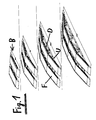
- FIG. 1 shows four possible bridges, each consisting of one or more bridge elements B.
- Each bridge element B consists of two carriageway slabs F, two lower chords U and several diagonal struts D.
- the bridges shown here vary in length from 6.5 to 27 meters.
- the truss-like structure according to the invention in which e.g. the roadway plates F form an arch and the lower chords U form an associated chord.
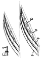
- Figure 2 shows bridges according to the invention with a length of 33.5 and 40 meters.
- Figure 3 shows a bridge element B. It consists of two roadway plates F, two lower chords U and eight diagonal struts D. Exemplary dimensions are given.
- the cross section through a bridge element B according to the invention is the To recognize cross member Q, which connects the two road plates F together.
- the diagonal struts D and the lower flange U could be sunk into the deck F for space-saving transport.
- the carriageway slab F has a U-shaped cross section. Other arrangements of the diagonal struts or struts that are approximately perpendicular to the roadway plate are also possible but not shown.
- the curvature of the bridge according to the invention can also be achieved via its length adjustment.
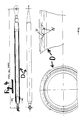
- FIG. 4 shows an embodiment of a diagonal strut D consisting of two parts which can be moved relative to one another.
- the strut can be changed in length from 3.1 to 3.8 meters.
- the length change and locking takes place with the help of projections V and grooves N, which can be brought into engagement with one another.
- the projections V and grooves N are of arcuate design here, as shown in FIG. 4 at the bottom left.
- Figure 5 shows two possible ramps R and R '.
- the ramp R shown above is rigid and has a slightly lower weight than the pivotable ramp R 'shown below.
- the ramps R and R 'each interact with the roadway plates F and the lower chords U. Exemplary dimensions for the swivel angle can be found in the figure.
- FIG. 6 shows an armored personnel carrier VP with 46 meter bridge.
- the bridge is mounted in the form of its bridge elements B on a slide SL.
- the carriage has a lifting and pivoting device. Its movement possibilities are shown in the bottom right of FIG. 6.
- the VP armored personnel carrier has a VB laying beam with a foot with which the tilting moment of the VP armored personnel carrier can be increased considerably. This makes it possible to lay up to 46 meters of bridge in the free porch.
- the installation armor VP also has in its middle part a support ST which can be moved up and down and which carries a roller on its top, on which the installation beam can be moved.
- Figure 7 shows the laying process with the laying armor VP.
- the bridge elements B are moved backwards with the slide SL and the laying beam VB is extended forward with the foot.
- the slide is tilted so that the bridge elements B can be brought to their intended height by extending the diagonal struts and the lower chords.
- the laying process is shown in an advanced stage.
- the finished bridge elements B are then coupled together on the laying vehicle VP and pushed over the obstacle via the laying beam VB. Exemplary information on the space requirement on the bank can be found in FIG. 7 below.
- Figure 8 shows various bridge combinations that a single laying vehicle can choose to lay. Either 4 x 13 meter long bridges or 2 x 24 meter long bridges or two 13 meter long and one 24 meter long bridge or one 35 meter long and one 13 meter long bridge or one 46 meter long bridge are to be laid.
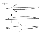
- FIG. 9 shows three types of bridges that can be built from the bridge elements B according to the invention.
- the carriageway formed by the carriageway slabs F
- the lower chord formed by the lower chords U
- Struts are not shown in this figure.
Landscapes
- Engineering & Computer Science (AREA)
- Architecture (AREA)
- Civil Engineering (AREA)
- Structural Engineering (AREA)
- Bridges Or Land Bridges (AREA)
Abstract
Description
- Die Erfindung betrifft eine Brücke nach dem Oberbegriff des Anspruchs 1.
- Aus der DE-PS 3138 853 ist eine zerlegbare Brücke bekannt, die aus zusammenkuppelbaren Brückenelementen gleicher Höhe besteht. Diese Brücke kann sehr schnell aufgebaut werden. Zum Transport einer 40 Meterbrücke sind aber immer noch mehrere Fahrzeuge notwendig.
- Aufgabe der Erfindung ist es, eine Brücke, insbesondere für militärische Zwecke, vorzuschlagen, die möglichst wenige Fahrzeuge benötigt und in ihrer Länge variabel aufstellbar ist.
- Diese Aufgabe wird erfindungsgemäß gelöst von einer Brücke mit den Merkmalen des Anspruchs 1. Ausführungen der Erfindung und ein Verlegepanzer zur Verwendung an dieser Brücke sind Gegenstände von Unteransprüchen.
- Erfindungsgemäß ist ein Fachwerk aus Streben und Untergurten vorgesehen, mit dem sich die einzelnen Brückenelemente in ihrer Höhe verstellen lassen - symmetrisch, so daß Fahrbahn und Untergurt parallel verlaufen, oder unsymmetrisch, so daß die Fahrbahn nicht parallel zum Untergurt verläuft. Damit lassen sich Brücken herstellen, bei denen die Fahrbahn und der Untergurt oder eines beider Bauelemente einen bogenförmigen Verlauf nimmt, sodaß die Brücke in ihrer Mitte höher ist als an ihren Enden. So können z.B. die Fahrbahnplatten einen Bogen und die Untergurte die dazugehörende Sehne bilden. Durch die verstellbare Höhe kann die Brücke dem Momentenverlauf angepaßt werden. Die erfindungsgemäße Gestaltung der Brückenelemente führt dazu, daß der Untergurt und die Diagonalstreben beim Transport auf sehr kleinen Raum zusammengefaltet werden können. Das geringe Gewicht und die kleinen Transportabmessungen erlauben im Fall einer Panzerbrücke die Gesamtlänge von ca. 40 Metern mit einem Fahrzeug zu transportieren. Da alle Brückenabschnitte gleich und auf einem Fahrzeug sind, läßt sich das Bauen und Verlegen von verschiedenen Brückenlängen gut automatisieren.
- Die erfindungsgemäße Brücke hat folgende Vorteile:
- wenig und kleine Ersatzteile
- wenig Windangriffsfläche
- wenig Beschußfläche
- große Variabilität, d.h., es können entweder eine sehr lange oder mehrere kurze Brücken gleichzeitig von einem Fahrzeug gebaut werden
- bis 45 Meter kein Vorbauträger nötig
- geringes Gewicht
- geringes Transportvolumen
- bessere Brückensicht des Panzerfahrers bei Anfahrt auf die Brücke
- Teile können von Hand ausgewechselt werden und auch als Ersatz mitgeführt werden (in einem Beispiel wiegt das Teleskop 56 kg, ein Untergurtabschnitt 150 kg, eine Kupplung 50 kg und eine Rampe 200 kg)
- höhere Eigenfrequenz dank steifer und kleinerer Masse
- bei Ausfall eines Brückenteils nur Reduzierung der Gesamtlänge und kein Ausfall des Gesamtsystems
- offene Struktur, wodurch Sicht zu Kupplungsstellen und anderen kritischen Stellen frei ist
- kein Aufrüsten hinter der Front, da alle Elemente austauschbar sind
- keine taktische Einschränkung (Entscheidung am Ziel über Brückenlänge). - Wesentlich für die Erfindung ist, daß die Längen von Fahrbahn und/oder Untergurt derBrückenelemente variabel sind, woraus sich eine veränderliche Höhe und/oder eine veränderbare Steigung von Untergurt zu Fahrbahn ergeben. Dies kann z.B. durch teleskopierbare und feststellbare Bauelemente (Fahrbahnplatten, Streben, und/oder Untergurte) oder durch Bauelemente erfolgen, die an ihren Enden in verschiedenen Abständen Koppelstellen aufweisen. In einer bevorzugten Ausführungsform sind die Diagonalstreben und/oder die Untergurte teleskopierbar. Sie können z.B. mit innenliegenden, bogenförmigen Nuten und Vorsprüngen ausgerüstet sein, sodaß durch Verdrehen der beiden Hälften eine Entriegelung erfolgt. Nach dem Auseinanderziehen oder Zusammenschieben kann der Träger in einer anderen Länge durch Verdrehen in eine andere Nut wieder verriegelt werden.
- Eine vom Gewicht her optimierte Ausführungsform weist pro Brückenelement zwei Fahrbahnplatten, zwei Untergurte und acht Diagonalstreben auf, die jeweils zwischen den Enden der Fahrbahnplatten und der Mitte der Untergurte angeordnet sind.
- Wenn die Fahrbahnplatten eine U-förmigen Querschnitt haben, können in ihrem Inneren die Diagonalstreben und die Untergurte Platz finden.
- In einer bevorzugten Ausführungsform werden zwei Fahrbahnplatten pro Brückenelement verwendet, die mit Querträgern miteinander verbunden sind. Genauso ist es jedoch möglich, statt der zwei Fahrbahnplatten eine breitere Fahrbahnplatte vorzusehen, die beide Spuren aufnimmt. Dies ist vorteilhaft für eine maschinelle Verlegung, wenn es auf die Tragbarkeit der Einzelteile nicht ankommt.
- Die Brücke weist dann ein besonders günstiges Verhältnis von Tragfähigkeit zu Gewicht auf, wenn ihr Höhen zu Längenverhältnis im Bereich von 1 : 10 bis 1 : 30 liegt, bevorzugt bei 1 : 20 liegt. Eine solche Brücke hat eine ausreichende Tragfähigkeit (MLC 60).
- Ein Verlegefahrzeug, z.B. ein Radfahrzeug oder ein Verlegepanzer, der zum Verlegen der erfindungsgemäßen Brücke geeignet ist, hat einen ausfahrbaren Verlegebalken mit einem Fuß, der das Kippmoment des gesamten Fahrzeugs verbessert, eine im Fahrzeug höhenverstellbare Stütze mit einer oder mehreren Rollen, auf der der Verlegebalken verschiebbar ist, und einen Schlitten, der angehoben und gekippt werden kann zur Aufnahme der Brückenelemente.
- Die Erfindung wird anhand von 8 Figuren näher erläutert. Es zeigen
- Figuren 1 und 2 mehrere erfindungsgemäße Brücken
- Figur 3 den Aufbau eines Brückenabschnitts
- Figur 4 eine Diagonalstrebe
- Figur 5 zwei Ausführungen von Rampen
- Figur 6 einen Verlegepanzer
- Figur 7 den Verlegevorgang und
- Figur 8 mehrere Brückenkombinationen, die mit einem Verlegefahrzeug verlegt werden können.
- Figur 9 3 Brücken unterschiedlicher Krümmungen.
- Figur 1 zeigt vier mögliche Brücken, die jeweils aus ein oder mehreren Brückenelementen B bestehen. Jedes Brückenelement B besteht hier aus zwei Fahrbahnplatten F, zwei Untergurten U und mehreren Diagonalstreben D. Die hier gezeigten Brücken variieren in ihrer Länge von 6,5 bis 27 Meter. Deutlich zu erkennen ist der erfindungsgemäße fachwerkartige Aufbau, bei dem z.B. die Fahrbahnplatten F einen Bogen und die Untergurte U eine dazugehörige Sehne bilden.
- Figur 2 zeigt erfindungsgemäße Brücken der Länge 33,5 und 40 Meter.
- Figur 3 zeigt ein Brückenelement B. Es besteht aus zwei Fahrbahnplatten F, zwei Untergurten U und acht Diagonalstreben D. Beispielhafte Bemaßungen sind angegeben. Im unteren Teil der Figur 3, dem Querschnitt durch ein erfindungsgegemäßes Brückenelement B ist der Querträger Q zu erkennen, der die beiden Fahrbahnplatten F miteinander verbindet. Die Diagonalstreben D und der Untergurt U könnten für den platzsparenden Transport in die Fahrbahnplatte F versenkt werden. Die Fahrbahnplatte F hat einen U-förmigen Querschnitt. Möglich aber nicht gezeigt sind auch andere Anordnungen der Diagonalstreben oder auch Streben die ungefähr senkrecht zur Fahrbahnplatte stehen. Über deren Längenverstellung kann ebenfalls die erfindungsgemäße Krümmung der Brücke erreicht werden.
- Figur 4 zeigt eine Ausführung einer Diagonalstrebe D aus zwei gegeneinander verschiebbaren Teilen. In diesem Beispiel ist die Strebe von 3,1 bis 3,8 Meter längenveränderbar. Die Längenveränderung und Verriegelung erfolgt mit Hilfe von Vorsprüngen V und Nuten N, die miteinander in Eingriff gebracht werden können. Die Vorsprünge V und Nuten N sind hier bogenförmig ausgeführt, wie Figur 4 links unten zeigt. Durch Verdrehen der zwei Teile des Diagonalträgers D können die Vorsprünge aus den Nuten herausgeschoben oder in die Nuten wieder eingerastet werden. Dadurch wird eine einfache Längenveränderung und Verriegelung ermöglicht.
- Figur 5 zeigt zwei mögliche Rampen R und R′. Die oben gezeigte Rampe R ist starr ausgeführt und hat ein etwas geringeres Gewicht als die unten gezeigte schwenkbare Rampe R′. Die Rampen R und R′ wirken jeweils mit den Fahrbahnplatten F und den Untergurten U zusammen. Beispielhafte Maßangaben für die Verschwenkwinkel sind der Figur zu entnehmen.
- Figur 6 zeigt einen Verlegepanzer VP mit 46 Meter Brücke. Die Brücke ist in Form ihrer Brückenelemente B auf einem Schlitten SL gelagert. Der Schlitten weist eine Hebe- und Verschwenkeinrichtung auf. Seine Bewegungsmöglichkeiten sind in der Figur 6 unten rechts angegeben. Der Verlegepanzer VP hat einen Verlegebalken VB, mit einem Fuß , mit dem das Kippmoment des Verlegepanzers VP erheblich erhöht werden kann. Damit ist es möglich,bis zu 46 Meter Brücke im freien Vorbau zu verlegen. Der Verlegepanzer VP weist weiterhin in seinem Mittelteil eine nach oben und unten verschiebbare Stütze ST auf, die an ihrer Oberseite eine Rolle trägt, auf der der Verlegebalken verschoben werden kann.
- Figur 7 zeigt den Verlegevorgang mit dem Verlegepanzer VP. Als erstes werden die Brückenelemente B mit dem Schlitten SL nach hinten verfahren und der Verlegebalken VB mit dem Fuß nach vorne ausgefahren. Im nächsten Schritt wird der Schlitten gekippt, sodaß die Brückenelemente B durch Ausfahren der Diagonalstreben und der Untergurte auf ihre vorgesehene Höhe gebracht werden können. Im untersten Bild ist der Verlegevorgang in einem fortgeschrittenen Stadium gezeigt. Die fertigen Brückenelemente B werden dann noch auf dem Verlegefahrzeug VP aneinandergekoppelt und über den Verlegebalken VB über das Hindernis geschoben. Beispielhafte Angaben für den Platzbedarf am Ufer sind der Figur 7 unten zu entnehmen.
- Figur 8 zeigt verschiedene Brückenkombinationen, die ein einziges Verlegefahrzeug wahlweise verlegen kann. Es können entweder 4 x 13 Meter lange Brücken oder 2 x 24 Meter lange Brücken oder zwei 13 Meter lange und eine 24 Meter lange Brücke oder eine 35 Meter lange und eine 13 Meter lange Brücke oder eine 46 Meter lange Brücke verlegt werden.
- Figur 9 zeigt drei Brückentypen, die aus den erfindungsgemäßen Brückenelementen B gebaut werden können.
Im oberen Teil ist die Fahrbahn, gebildet durch die Fahrbbahnplatten F, eben und der Untergurt, gebildet durch die Untergurte U, gekrümmt. Im mittleren Teil der Figur ist die Fahrbahn gekrümmt, die Untergurte verlaufen gerade. Im unteren Teil sind die Fahrbahn und die Untergurte gekrümmt. Abstrebungen sind in dieser Figur nicht gezeichnet.
Claims (10)
Applications Claiming Priority (2)
| Application Number | Priority Date | Filing Date | Title |
|---|---|---|---|
| DE3814502 | 1988-04-29 | ||
| DE3814502A DE3814502C3 (de) | 1988-04-29 | 1988-04-29 | Brücke |
Publications (3)
| Publication Number | Publication Date |
|---|---|
| EP0340409A1 true EP0340409A1 (de) | 1989-11-08 |
| EP0340409B1 EP0340409B1 (de) | 1991-12-27 |
| EP0340409B2 EP0340409B2 (de) | 1995-12-27 |
Family
ID=6353180
Family Applications (1)
| Application Number | Title | Priority Date | Filing Date |
|---|---|---|---|
| EP89103833A Expired - Lifetime EP0340409B2 (de) | 1988-04-29 | 1989-03-04 | Brücke |
Country Status (3)
| Country | Link |
|---|---|
| US (1) | US5042101A (de) |
| EP (1) | EP0340409B2 (de) |
| DE (1) | DE3814502C3 (de) |
Cited By (5)
| Publication number | Priority date | Publication date | Assignee | Title |
|---|---|---|---|---|
| GB2258485A (en) * | 1991-08-08 | 1993-02-10 | Gutehoffnungshuette Man | Bridge-forming system |
| FR2683837A1 (fr) * | 1991-11-15 | 1993-05-21 | Mediterranee Const Ind | Structure de travure destinee en particulier au franchissement de breches par des vehicules et systeme de transport et de depose de la structure. |
| EP0600330B2 (de) † | 1992-12-01 | 1999-05-19 | MAN Technologie AG | Zerlegbare Brücke |
| CN105603863A (zh) * | 2015-12-29 | 2016-05-25 | 大同煤矿集团有限责任公司 | 综采安全出口行人推拉折叠式过桥 |
| CN110106789A (zh) * | 2019-04-30 | 2019-08-09 | 中国人民解放军陆军工程大学 | 一种钛/铝/钛轻质高强度应急桥梁及架设方法 |
Families Citing this family (27)
| Publication number | Priority date | Publication date | Assignee | Title |
|---|---|---|---|---|
| IT89068157A1 (it) * | 1989-12-22 | 1991-06-24 | Giuseppe Drago | Ponte a struttura modulare e procedimento di varo per la sua posa in opera |
| DE4009639C2 (de) * | 1990-03-26 | 1994-04-28 | Dornier Gmbh | Verlegeeinrichtung |
| SE467932B (sv) * | 1990-04-18 | 1992-10-05 | Karlskronavarvet Ab | Byggsats foer byggande av en bro samt broelement, vagn och stoedbenpar ingaaende daeri |
| DE4038763A1 (de) * | 1990-12-05 | 1992-06-11 | Krupp Industrietech | Zerlegbare bruecke und fahrzeug zum verlegen der bruecke |
| DE4137500C1 (de) * | 1991-11-14 | 1992-11-26 | Dornier Gmbh, 7990 Friedrichshafen, De | |
| EP0563872B1 (de) * | 1992-03-31 | 1996-05-29 | Krupp Fördertechnik GmbH | Verlegbare Brücke und Fahrzeug zum Verlegen der Brücke |
| EP0563418A1 (de) * | 1992-03-31 | 1993-10-06 | Krupp Industrietechnik Gmbh | Verlegbare Brücke und Fahrzeug zum Verlegen der Brücke |
| DE4240271A1 (de) * | 1992-12-01 | 1994-06-09 | Krupp Foerdertechnik Gmbh | Zerlegbare Brücke |
| DE4240574A1 (de) * | 1992-12-03 | 1994-06-09 | Krupp Foerdertechnik Gmbh | Verlegbare Brücke |
| DE4433938C2 (de) * | 1993-07-31 | 2001-03-01 | Man Technologie Gmbh | Zerlegbare und zusammenklappbare Fußgängerbrücke |
| DE4325779C2 (de) * | 1994-09-23 | 1999-07-22 | Man Technologie Gmbh | Zerlegbare und zusammenklappbare Fußgängerbrücke |
| DE4331254C2 (de) * | 1993-09-15 | 2000-01-27 | Dornier Gmbh | Brücke |
| DE19643810C2 (de) * | 1996-10-30 | 1998-12-10 | Krupp Foerdertechnik Gmbh | Handhabungsgerät für ein Brückenlegesystem |
| DE19813542C1 (de) * | 1998-03-27 | 1999-07-22 | Mak System Gmbh | Räum- und Stützschild |
| US6421863B1 (en) | 2000-09-25 | 2002-07-23 | Custom Manufacturing, Inc. | Portable bridge footings and abutments |
| US6799345B2 (en) * | 2003-01-02 | 2004-10-05 | David Occhiolini | Footbridge support |
| DE10307858B3 (de) | 2003-02-25 | 2004-06-09 | Dornier Gmbh | Zerlegbare Brücke |
| US7091640B2 (en) * | 2004-05-26 | 2006-08-15 | Emerson Electric Co. | Motor with a multifunction bearing cap and method of assembly |
| DE102004049969B8 (de) * | 2004-10-14 | 2006-03-23 | Military Mobile Bridges Gmbh | Modulare Scherenbrücke sowie Verlegeeinrichtung und Verfahren zum Verlegen zerlegbarer Brücken |
| FR2901817B1 (fr) * | 2006-05-31 | 2015-03-27 | Deschamps A & Fils Ets | Pont temporaire |
| US20130047351A1 (en) | 2011-08-31 | 2013-02-28 | Marc Breault | Pipeline crossing bridge |
| USD735435S1 (en) * | 2013-12-01 | 2015-07-28 | Nicholas A. Guido, III | Wet area bridge |
| DE102015103209A1 (de) * | 2015-03-05 | 2016-09-08 | Wilhelm Layher Verwaltungs-Gmbh | Fachwerkrahmen, modularer Fachwerkträger und Überbrückungs- und/oder Tragkonstruktion |
| PT109392A (pt) | 2016-05-16 | 2017-11-16 | Pgpi - Marcas E Patentes S A | Disposição estrutural modular, sistema de construção de uma ponte e processo de construção de uma ponte |
| RU171265U1 (ru) * | 2016-12-20 | 2017-05-26 | Федеральное государственное казенное военное образовательное учреждение высшего образования "ВОЕННАЯ АКАДЕМИЯ МАТЕРИАЛЬНО-ТЕХНИЧЕСКОГО ОБЕСПЕЧЕНИЯ имени генерала армии А.В. Хрулева" | Поворотная стойка шпренгельной системы для автодорожных разборных мостов |
| US10179979B1 (en) * | 2017-07-12 | 2019-01-15 | Tidy Site Services, LLC | Bridge span and methods of moving a bridge span |
| RU177132U1 (ru) * | 2017-08-08 | 2018-02-09 | Федеральное государственное казенное военное образовательное учреждение высшего образования "ВОЕННАЯ АКАДЕМИЯ МАТЕРИАЛЬНО-ТЕХНИЧЕСКОГО ОБЕСПЕЧЕНИЯ имени генерала армии А.В. Хрулева" | Конструкция облегчённого раскладного пролётного строения металлической эстакады рэм - 500 |
Citations (5)
| Publication number | Priority date | Publication date | Assignee | Title |
|---|---|---|---|---|
| GB2039311A (en) * | 1978-11-24 | 1980-08-06 | Porsche Ag | Transportable bridge having means for folding the spans of the bridge |
| WO1980002166A1 (en) * | 1979-04-03 | 1980-10-16 | P Wesseltoft | Prefabricated footway |
| EP0075671A1 (de) * | 1981-09-30 | 1983-04-06 | DORNIER SYSTEM GmbH | Zerlegbare Festbrücke |
| GB2155979A (en) * | 1984-03-12 | 1985-10-02 | Dietrich Sa | Lightweight lattice bridge |
| EP0256446A2 (de) * | 1986-08-20 | 1988-02-24 | Fried. Krupp AG Hoesch-Krupp | Verlegesystem für eine zerlegbare Brücke |
Family Cites Families (11)
| Publication number | Priority date | Publication date | Assignee | Title |
|---|---|---|---|---|
| DE298738C (de) * | ||||
| US879524A (en) * | 1907-09-19 | 1908-02-18 | Abe Cartwright | Adjustable brace. |
| BE634986A (de) * | 1962-07-14 | |||
| IT1001125B (it) * | 1973-12-20 | 1976-04-20 | Lotto S | Ponte di servizio estemporaneo mo dulare componibile automontato ed autovariabile |
| SU749970A2 (ru) * | 1977-01-06 | 1980-07-23 | Военно-Инженерная Ордена Ленина Краснознаменная Академия Им. В.В.Куйбышева | Пролетное строение временного моста |
| DE2926594A1 (de) * | 1979-07-02 | 1981-01-15 | Systemtechnik Gmbh | Brueckenlegefahrzeug |
| DD212279A1 (de) * | 1982-12-17 | 1984-08-08 | Metalleichtbau Veb K | Vorrichtung zum unterspannen von brueckenelementen |
| DE3421771A1 (de) * | 1984-06-12 | 1985-12-12 | Eisenwerke Kaiserslautern Göppner GmbH, 6750 Kaiserslautern | Provisorische festbruecke fuer den militaerischen einsatz |
| GB2165872B (en) * | 1984-10-24 | 1988-01-20 | Mabey & Johnson Ltd | Lattice panel bridge |
| US4635311A (en) * | 1985-06-10 | 1987-01-13 | The United States Of America As Represented By The Secretary Of The Army | Military tactical bridge system, method and foldable modules |
| FR2597129B1 (fr) * | 1986-04-11 | 1988-09-02 | Dietrich & Cie De | Travure legere repliable pour le franchissement de breches par des engins dits lourds, notamment des engins blindes |
-
1988
- 1988-04-29 DE DE3814502A patent/DE3814502C3/de not_active Expired - Lifetime
-
1989
- 1989-03-04 EP EP89103833A patent/EP0340409B2/de not_active Expired - Lifetime
- 1989-04-27 US US07/343,734 patent/US5042101A/en not_active Expired - Lifetime
Patent Citations (5)
| Publication number | Priority date | Publication date | Assignee | Title |
|---|---|---|---|---|
| GB2039311A (en) * | 1978-11-24 | 1980-08-06 | Porsche Ag | Transportable bridge having means for folding the spans of the bridge |
| WO1980002166A1 (en) * | 1979-04-03 | 1980-10-16 | P Wesseltoft | Prefabricated footway |
| EP0075671A1 (de) * | 1981-09-30 | 1983-04-06 | DORNIER SYSTEM GmbH | Zerlegbare Festbrücke |
| GB2155979A (en) * | 1984-03-12 | 1985-10-02 | Dietrich Sa | Lightweight lattice bridge |
| EP0256446A2 (de) * | 1986-08-20 | 1988-02-24 | Fried. Krupp AG Hoesch-Krupp | Verlegesystem für eine zerlegbare Brücke |
Cited By (9)
| Publication number | Priority date | Publication date | Assignee | Title |
|---|---|---|---|---|
| GB2258485A (en) * | 1991-08-08 | 1993-02-10 | Gutehoffnungshuette Man | Bridge-forming system |
| GB2258485B (en) * | 1991-08-08 | 1994-12-07 | Gutehoffnungshuette Man | Bridge-forming system |
| FR2683837A1 (fr) * | 1991-11-15 | 1993-05-21 | Mediterranee Const Ind | Structure de travure destinee en particulier au franchissement de breches par des vehicules et systeme de transport et de depose de la structure. |
| EP0543711A1 (de) * | 1991-11-15 | 1993-05-26 | Constructions Industrielles De La Mediterranee- Cnim | Brückenteil, insbesondere zur Überwindung von Gräben durch Fahrzeuge |
| US5363527A (en) * | 1991-11-15 | 1994-11-15 | Constructions Industrielles De La Mediterranee Cnim | Spanning beam structure for clearing breaches by vehicles |
| EP0685599A1 (de) * | 1991-11-15 | 1995-12-06 | Constructions Industrielles De La Mediterranee- Cnim | System zum Transportieren von mindestens zwei Brückenteilen durch ein Fahrzeug zur Überwindung von Gräben und System zum Ablegen dieser Teile über die Graben durch das Fahrzeug |
| EP0600330B2 (de) † | 1992-12-01 | 1999-05-19 | MAN Technologie AG | Zerlegbare Brücke |
| CN105603863A (zh) * | 2015-12-29 | 2016-05-25 | 大同煤矿集团有限责任公司 | 综采安全出口行人推拉折叠式过桥 |
| CN110106789A (zh) * | 2019-04-30 | 2019-08-09 | 中国人民解放军陆军工程大学 | 一种钛/铝/钛轻质高强度应急桥梁及架设方法 |
Also Published As
| Publication number | Publication date |
|---|---|
| US5042101A (en) | 1991-08-27 |
| EP0340409B2 (de) | 1995-12-27 |
| DE3814502A1 (de) | 1989-11-09 |
| DE3814502C3 (de) | 1995-08-03 |
| DE3814502C2 (de) | 1991-12-12 |
| EP0340409B1 (de) | 1991-12-27 |
Similar Documents
| Publication | Publication Date | Title |
|---|---|---|
| EP0340409B1 (de) | Brücke | |
| DE3138853A1 (de) | "zerlegbare festbruecke" | |
| DE3218329A1 (de) | System von vorgefertigten betonelementen fuer den bau von wegen | |
| DE3117314A1 (de) | Roll- oder rutschbahn, insbesondere zum abfahren mit ungelenkten fahrzeugen | |
| EP0685600A1 (de) | Montageverfahren für eine verlegbare Brücke und nach dem Verfahren zusammengesetzte Brücke | |
| EP0391149A2 (de) | Verlegbare Brücke und System zum Verlegen der Brücke | |
| DE10127136A1 (de) | Militärisches Schnellbaubrückensystem | |
| DE4126250C2 (de) | Aus Spurträgern bestehendes Brückensystem | |
| EP0600356A1 (de) | Verlegbare Brücke | |
| DE4305764A1 (de) | Verlegbare Brücke und Einrichtung zum Verlegen der Brücke | |
| DE2353019C2 (de) | Fahrzeug zum Transport und teilweisen Zusammenbau einer aus vier einzelnen Brückenbalken bestehenden Verlegebrücke | |
| EP1905900A2 (de) | Brücke mit zwei fachwerkartig ausgebildeten Scheiben und Bausatz zu deren Herstellung | |
| EP0449064A1 (de) | Verlegeeinrichtung | |
| DE1246008B (de) | Haupttraeger fuer zerlegbare Bruecken | |
| EP0541948B1 (de) | Brücke | |
| EP1584748A2 (de) | Brückenverlegeeinrichtung | |
| DE3508437C2 (de) | Aus einzelnen Segmenten gebildete, zerlegbare Fachwerkbrücke | |
| EP0600330B2 (de) | Zerlegbare Brücke | |
| EP0168725A2 (de) | Lange Brücke | |
| EP0600329B1 (de) | Zerlegbare Brücke | |
| DE1872020U (de) | Transportable ueberfuehrung fuer den strassenverkehr. | |
| DE4240575A1 (de) | Verlegbare Brücke | |
| DE2227444C3 (de) | Mehrfeldrige, zerlegbare Brücke | |
| DE1708686C3 (de) | Haupttraeger fuer zerlegbare Bruecken | |
| DE3000673A1 (de) | Fahrstrasse fuer gummibereifte radfahrzeuge auf bruecken |
Legal Events
| Date | Code | Title | Description |
|---|---|---|---|
| PUAI | Public reference made under article 153(3) epc to a published international application that has entered the european phase |
Free format text: ORIGINAL CODE: 0009012 |
|
| AK | Designated contracting states |
Kind code of ref document: A1 Designated state(s): CH FR GB IT LI SE |
|
| 17P | Request for examination filed |
Effective date: 19891102 |
|
| 17Q | First examination report despatched |
Effective date: 19901218 |
|
| GRAA | (expected) grant |
Free format text: ORIGINAL CODE: 0009210 |
|
| AK | Designated contracting states |
Kind code of ref document: B1 Designated state(s): CH FR GB IT LI SE |
|
| GBT | Gb: translation of ep patent filed (gb section 77(6)(a)/1977) | ||
| ET | Fr: translation filed | ||
| ITF | It: translation for a ep patent filed |
Owner name: JACOBACCI & PERANI S.P.A. |
|
| PLBI | Opposition filed |
Free format text: ORIGINAL CODE: 0009260 |
|
| 26 | Opposition filed |
Opponent name: KRUPP INDUSTRIETECHNIK GMBH, PATENTABTEILUNG Effective date: 19920925 |
|
| EAL | Se: european patent in force in sweden |
Ref document number: 89103833.3 |
|
| PUAH | Patent maintained in amended form |
Free format text: ORIGINAL CODE: 0009272 |
|
| STAA | Information on the status of an ep patent application or granted ep patent |
Free format text: STATUS: PATENT MAINTAINED AS AMENDED |
|
| 27A | Patent maintained in amended form |
Effective date: 19951227 |
|
| AK | Designated contracting states |
Kind code of ref document: B2 Designated state(s): CH FR GB IT LI SE |
|
| REG | Reference to a national code |
Ref country code: CH Ref legal event code: AEN Free format text: AUFRECHTERHALTUNG DES PATENTES IN GEAENDERTER FORM |
|
| ITF | It: translation for a ep patent filed |
Owner name: JACOBACCI & PERANI S.P.A. |
|
| GBTA | Gb: translation of amended ep patent filed (gb section 77(6)(b)/1977) |
Effective date: 19960228 |
|
| ET3 | Fr: translation filed ** decision concerning opposition | ||
| REG | Reference to a national code |
Ref country code: GB Ref legal event code: 746 Effective date: 19991213 |
|
| REG | Reference to a national code |
Ref country code: FR Ref legal event code: D6 |
|
| REG | Reference to a national code |
Ref country code: GB Ref legal event code: IF02 |
|
| REG | Reference to a national code |
Ref country code: GB Ref legal event code: 732E |
|
| REG | Reference to a national code |
Ref country code: CH Ref legal event code: PUE Owner name: EUROBRIDGE MOBILE BRUECKEN GMBH Free format text: DORNIER GMBH#POSTFACH 1420#D-88004 FRIEDRICHSHAFEN (DE) -TRANSFER TO- EUROBRIDGE MOBILE BRUECKEN GMBH##88039 FRIEDRICHSHAFEN (DE) Ref country code: CH Ref legal event code: NV Representative=s name: R. A. EGLI & CO. PATENTANWAELTE |
|
| REG | Reference to a national code |
Ref country code: FR Ref legal event code: TP |
|
| PGFP | Annual fee paid to national office [announced via postgrant information from national office to epo] |
Ref country code: SE Payment date: 20050310 Year of fee payment: 17 |
|
| PG25 | Lapsed in a contracting state [announced via postgrant information from national office to epo] |
Ref country code: SE Free format text: LAPSE BECAUSE OF NON-PAYMENT OF DUE FEES Effective date: 20060305 |
|
| REG | Reference to a national code |
Ref country code: GB Ref legal event code: 732E |
|
| EUG | Se: european patent has lapsed | ||
| PGFP | Annual fee paid to national office [announced via postgrant information from national office to epo] |
Ref country code: IT Payment date: 20070625 Year of fee payment: 19 |
|
| PGFP | Annual fee paid to national office [announced via postgrant information from national office to epo] |
Ref country code: CH Payment date: 20080314 Year of fee payment: 20 |
|
| PGFP | Annual fee paid to national office [announced via postgrant information from national office to epo] |
Ref country code: GB Payment date: 20080320 Year of fee payment: 20 |
|
| PGFP | Annual fee paid to national office [announced via postgrant information from national office to epo] |
Ref country code: FR Payment date: 20080314 Year of fee payment: 20 |
|
| REG | Reference to a national code |
Ref country code: CH Ref legal event code: PL |
|
| REG | Reference to a national code |
Ref country code: GB Ref legal event code: PE20 Expiry date: 20090303 |
|
| PG25 | Lapsed in a contracting state [announced via postgrant information from national office to epo] |
Ref country code: GB Free format text: LAPSE BECAUSE OF EXPIRATION OF PROTECTION Effective date: 20090303 |
|
| PG25 | Lapsed in a contracting state [announced via postgrant information from national office to epo] |
Ref country code: IT Free format text: LAPSE BECAUSE OF NON-PAYMENT OF DUE FEES Effective date: 20080304 |