EP0317140B1 - Tintenstrahlaufzeichnungsapparat - Google Patents
Tintenstrahlaufzeichnungsapparat Download PDFInfo
- Publication number
- EP0317140B1 EP0317140B1 EP88310419A EP88310419A EP0317140B1 EP 0317140 B1 EP0317140 B1 EP 0317140B1 EP 88310419 A EP88310419 A EP 88310419A EP 88310419 A EP88310419 A EP 88310419A EP 0317140 B1 EP0317140 B1 EP 0317140B1
- Authority
- EP
- European Patent Office
- Prior art keywords
- recording
- printing
- thinning
- dot
- Prior art date
- Legal status (The legal status is an assumption and is not a legal conclusion. Google has not performed a legal analysis and makes no representation as to the accuracy of the status listed.)
- Expired - Lifetime
Links
- 230000000694 effects Effects 0.000 claims description 4
- 238000010438 heat treatment Methods 0.000 claims description 3
- 238000007599 discharging Methods 0.000 claims 2
- 238000000034 method Methods 0.000 description 24
- 239000000463 material Substances 0.000 description 22
- 238000001514 detection method Methods 0.000 description 3
- 230000007613 environmental effect Effects 0.000 description 3
- 239000007787 solid Substances 0.000 description 3
- 238000013461 design Methods 0.000 description 2
- 238000010586 diagram Methods 0.000 description 2
- 239000011159 matrix material Substances 0.000 description 2
- 238000012545 processing Methods 0.000 description 2
- 230000015572 biosynthetic process Effects 0.000 description 1
- 239000003990 capacitor Substances 0.000 description 1
- 238000010276 construction Methods 0.000 description 1
- 238000007796 conventional method Methods 0.000 description 1
- 230000010485 coping Effects 0.000 description 1
- 230000003247 decreasing effect Effects 0.000 description 1
- 238000012840 feeding operation Methods 0.000 description 1
- 239000007788 liquid Substances 0.000 description 1
- 238000012423 maintenance Methods 0.000 description 1
- 230000002093 peripheral effect Effects 0.000 description 1
- 239000002985 plastic film Substances 0.000 description 1
- 238000002360 preparation method Methods 0.000 description 1
Images

Classifications
-
- B—PERFORMING OPERATIONS; TRANSPORTING
- B41—PRINTING; LINING MACHINES; TYPEWRITERS; STAMPS
- B41J—TYPEWRITERS; SELECTIVE PRINTING MECHANISMS, i.e. MECHANISMS PRINTING OTHERWISE THAN FROM A FORME; CORRECTION OF TYPOGRAPHICAL ERRORS
- B41J2/00—Typewriters or selective printing mechanisms characterised by the printing or marking process for which they are designed
- B41J2/485—Typewriters or selective printing mechanisms characterised by the printing or marking process for which they are designed characterised by the process of building-up characters or image elements applicable to two or more kinds of printing or marking processes
- B41J2/505—Typewriters or selective printing mechanisms characterised by the printing or marking process for which they are designed characterised by the process of building-up characters or image elements applicable to two or more kinds of printing or marking processes from an assembly of identical printing elements
- B41J2/5056—Typewriters or selective printing mechanisms characterised by the printing or marking process for which they are designed characterised by the process of building-up characters or image elements applicable to two or more kinds of printing or marking processes from an assembly of identical printing elements using dot arrays providing selective dot disposition modes, e.g. different dot densities for high speed and high-quality printing, array line selections for multi-pass printing, or dot shifts for character inclination
- B41J2/5058—Typewriters or selective printing mechanisms characterised by the printing or marking process for which they are designed characterised by the process of building-up characters or image elements applicable to two or more kinds of printing or marking processes from an assembly of identical printing elements using dot arrays providing selective dot disposition modes, e.g. different dot densities for high speed and high-quality printing, array line selections for multi-pass printing, or dot shifts for character inclination locally, i.e. for single dots or for small areas of a character
-
- B—PERFORMING OPERATIONS; TRANSPORTING
- B41—PRINTING; LINING MACHINES; TYPEWRITERS; STAMPS
- B41J—TYPEWRITERS; SELECTIVE PRINTING MECHANISMS, i.e. MECHANISMS PRINTING OTHERWISE THAN FROM A FORME; CORRECTION OF TYPOGRAPHICAL ERRORS
- B41J2/00—Typewriters or selective printing mechanisms characterised by the printing or marking process for which they are designed
- B41J2/005—Typewriters or selective printing mechanisms characterised by the printing or marking process for which they are designed characterised by bringing liquid or particles selectively into contact with a printing material
- B41J2/01—Ink jet
- B41J2/17—Ink jet characterised by ink handling
- B41J2/195—Ink jet characterised by ink handling for monitoring ink quality
Definitions
- This invention relates to an ink jet recording method, and in particular to an ink jet recording method in which the fixativeness after printing is effected on a recording sheet such as a sheet material is improved.
- An apparatus for printing characters (including ordinary images such as figures) by the use of an ink jet head such as an ink jet printer or an ink jet recorder, is designed such that ink droplet discharge means provided in the ink jet head is driven on the basis of character information and character patterns are recorded by print dots formed by ink droplets adhering to a recording sheet.
- the number of dots per character is in the tendency toward an increase to improve the quality of print or improve the resolution of image, and for example, there is seen the tendency toward an increase from a head of vertical 9 dots to 24 dots, and further to 32 dots or 48 dots.
- fixativeness of printed characters is governed by environmental conditions such as temperature and humidity, but the prior art has encountered difficulties in coping with these environmental conditions.
- a recording apparatus comprising: feeding means for feeding a recording medium; control means for changing a dot thinning rate; and recording means for recording on the recording medium in accordance with the dot thinning rate controlled by said control means, characterised in that there are humidity detecting means disposed proximate to a feeding path of said feeding means for detecting a humidity of said recording means, and for generating a signal indicative of the humidity value, and in that the control means change the dot thinning rate in dependence upon the signal fed thereto by said detecting means.
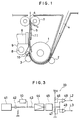
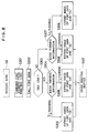
- Figure 1 is a longitudinal cross-sectional view of an ink jet recording apparatus suitable for carrying out the present invention.
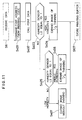
- FIG. 2 is a block diagram of a control system suitable for carrying out the present invention.
- Figure 3 diagrammatically shows the humidity detecting circuit in Figure 2.
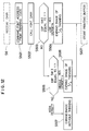
- Figure 4 is a flow chart showing the operation procedure of an ink jet recording method according to an embodiment of the present invention.
- Figure 5 is a flow chart of a first embodiment of the printing operation in Figure 4.
- Figure 6 is a flow chart showing the specific procedure of the thinning control in Figure 5.
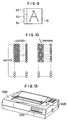
- Figure 7 is a schematic illustration of a dot image in which 1/2 thinning has been effected.
- Figure 8 is a flow chart of a second embodiment of the printing operation in Figure 4.
- Figure 9 is a schematic illustration showing a memory for character font data.
- Figure 10 is a schematic illustration showing the 1/4-thinned state.
- Figure 11 is a flow chart of a third embodiment of the recording operation in Figure 4.
- Figure 12 is a flow chart of a fourth embodiment of the recording operation in Figure 4.
- Figure 13 is a schematic perspective view of an ink jet recording apparatus provided with the essential portions of the ink jet recording apparatus shown in Figure 1.
- Figure 1 is a longitudinal cross-sectional view of an ink jet recording apparatus suitable for carrying out an ink jet recording method according to the present invention.
- a sheet material (a sheet-like) recording medium including a plastic sheet or the like 4 is supplied in the direction of arrow to a sheet feeding mechanism comprising a feed roller 1 and pinch rollers 2 and 3 separably urged against the lower peripheral surface thereof, and printing (formation of characters, figures and other images) is effected on the sheet material 4 while the sheet material 4 is pitch-fed through a recording station between a platen and an ink jet head 6.
- ink jet head use is made of a head which utilizes heat energy to discharge ink as droplets and form images, as shown, for example, in U.S.Patent No. 4,723,129.
- the sheet material 4 is discharged upward through discharge rollers 7.
- the shown recording apparatus is a serial type one, and the ink jet head 6 having ink discharge ports is carried on a carriage 9 reciprocally movable to the left and right along the front face of the platen 5 (the sheet material 4) along a guide shaft 8.
- an ink jet recording apparatus which prints characters comprising dot patterns of ink droplets on the sheet material 4 on the basis of character data supplied from a computer or the like.
- a humidity sensor 10 is mounted at a location near to the path of the sheet material 4 between the pinch roller 3 and the printing head 6, and a fixing heater 11 for heating the sheet material 4 to expedite the desiccation of print is disposed within the range through which the portion of the sheet material 4 passes immediately after printing.
- an ink jet recording method is carried out which can improve the fixativeness after printing by thinning printing dots and effecting printing during a printing mode having many printing dots or when recording characters.
- characters include ordinary characters and all kinds of images including figures and picture elements.
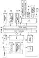
- FIG. 2 is a block diagram of a control system suitable for carrying out the ink jet recording method according to the present invention.
- control unit 21 of the recording apparatus is connected to a host computer or the like through an I/O port 22 and receives a printing command and printing data.
- an ROM 25 storing a control program, etc. therein, a character generator 26 storing font data of various characters, etc. therein, an RAM 27 having a print buffer or the like, an I/O port 28 for transmitting a control signal to various operating portions and receiving detection signals from various sensors, and a head control 29 for controlling the ink jet head 6.
- a motor 30 for driving the carriage 9 a sheet feed motor 31 for driving the feed roller 1, a dip switch 32 for setting thinned prints and the kinds thereof, a circuit 33 generating a humidity detection signal on the basis of the detected humidity, and a fixing heater controlling circuit 34 for switching on and off the fixing heater in conformity with set conditions are connected through the I/O port 28.
- a level signal from the humidity sensor 10 is supplied into the humidity detecting circuit 33.
- the fixing heater controlling circuit 34 controls the driving current from a power source 35 to the fixing heater 11 on the basis of the heater temperature, etc.
- Figure 3 shows the construction of the humidity detecting circuit 33 in Figure 2.
- the detecting circuit 33 of Figure 3 is designed to apply an AC voltage to the sensor unit 10 and detect the humidity of two points (comparators 48 and 49).
- the output signal from an oscillator 41 has its DC component removed through a capacitor 42, and a voltage divided by a serial circuit comprising the sensor unit 10 and a reference resistor 43 is rectified by a rectifying circuit comprising an OP amplifier 44 and a diode 45, and has its DC voltage exchanged.
- This DC voltage is compared with a reference voltage produced by resistors 46 and 47, by comparators 48 and 49, and detection of the humidity of two points (L2 and L3) is effected.
- the humidity has reached a set value or more by the two points (L2 and L3) at which the humidity changes from "0" to "1" is detected.
- Figure 4 is a flow chart showing the operation procedure when the method of the present invention is carried out in the above-described ink jet recording apparatus.
- step S1 when the power switch is closed, at step S1, the control circuit 21, the interior of the RAM 27 and various operating portions are initially set and the ROM, the RAM and the movement of the carriage are checked, and advance is made to the next step S2, where the fixing heater 11 is actuated.
- step S3 where whether the sheet material 4 has been supplied is discriminated by a sheet absence sensor.
- step S4 advance is made to step S4, where an on-line lamp representing the completion of the connection to a host machine such as a computer is turned on, and at step S5, an interface signal representative of the completion of the preparation for receiving data is output, and then advance is made to the next step S6, where data is received.
- step S7 When data is received, advance is made to step S7, where recording of one line is effected on the sheet material 4, and when the recording of one line is completed, sheet feeding is effected at step S8, whereafter advance is made to step S9, where whether the sheet feed motor and the carriage motor have been stopped is discriminated.
- step S9 If the motors are not stopped at step S9, return is made to step S8, where the sheet feeding operation is continued.
- step S9 If the stoppage of the motors is confirmed at step S9, return is made to step S4, where the above-described operation is repeated to effect recording of the next line.
- step S3 If the absence of the sheet material is judged at the step S3, a paper lamp is turned on at step S10, and error processing is effected at step S11. Subsequently, advance is made to step S12, where whether the error has been released is discriminated, and if the error has not been released, the discrimination of step S12 is effected at each predetermined interval.
- step S3 where the presence or absence of the sheet material 4 is discriminated and error processing is repeated until the sheet material 4 is supplied.
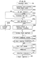
- FIG. 5 is a flow chart showing the detailed procedure of the recording operation at the step S7 in Figure 4.
- step S101 when at step S6, data is received and the recording operation is entered, at step S101, a font address is designated from a printing data code stored in the input buffer area of the RAM 27 transferred from the host, and advance is made to the next step S102, where whether printing of an ordinary character or printing of a bit image is to be effected is discriminated.
- step S103 If a bit image is to be printed, whether thinning should be effected during the printing of the bit image, that is, whether the mode is set to thinned print in the state of the dip switch, is discriminated at step S103, and if the thinning switch is not ON, whether the character to be printed is BGC (block graphic character) printing or reverse printing (hollow character printing) or not is discriminated at the next step S104.
- BGC block graphic character
- reverse printing high character printing
- step S105 If the character to be printed is BGC print or reverse print, advance is made to step S105, where the image is expanded and predetermined thinning control is effected.
- BGC and reverse printing data are image-expanded and predetermined thinning control is effected, whereafter at step S107, they are stored into a print buffer in the RAM 27.
- step S102 If at the step S102, a bit image is not to be printed, advance is immediately made to step S104, where whether BGC printing or reverse printing should be effected is discriminated.
- step S103 the state is a state in which thinning is effected during bit image printing (the ON state of the dip switch)
- step S105 the data of bit image printing is image-expanded and predetermined thinning control is effected, whereafter at step S107, it is stored into the print buffer in the RAM 27.
- step S104 the printing data is neither BGC printing nor reverse printing (in the present embodiment, the case of an ordinary character)
- the image is expanded at step S106, whereafter advance is made to step S107, where the image-expanded data is stored into the print buffer in the RAM 27.
- step S107 the image data of the character is stored into the print buffer, the carriage motor is driven at step S108, and whether the carriage 9 (or the ink jet head 6) is in the print starting position is discriminated at step S109.
- step S110 When the arrival of the carriage 9 at the print starting position is detected, a dot image is called at step S110, and printing is effected at step S111.
- step S112 whether the carriage 9 has arrived at one-line print finishing position is detected, and printing is executed until the carriage arrives at said print finishing position, and when the carriage arrives at said print finishing position, advance is made to the step S8 of Figure 4, where sheet feeding is effected.
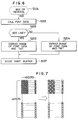
- Figure 6 is a flow chart illustrating the specific operations of image expansion and thinning control of BGC or reverse printing data at step S105 during the recording operation of Figure 5, and Figure 7 is a developed view showing the thinning control of Figure 6 in the form of dot images.
- step S201 where the font data in the CG 26 is called, and at step S202, whether the font data is of an odd line or of an even line is discriminated.
- step S203 If the font data is the data of an odd line, advance is made to step S203, where AND of the font data and "AA" is taken and the image is expanded, and at the step S107 of Figure 5, that dot image is stored into the print buffer.
- step S204 where AND of the font data and "55" is taken and the image is expanded, and at the step S107 of Figure 5, that dot image is stored into the print buffer.
- dot thinning is effected in a staggered fashion for each line from a dot matrix, and thinned print in which the dot density is 1/2, that is, the thinning rate is 50%, can be accomplished.
- Figure 8 is a flow chart showing another operation procedure (embodiment) of the recording operation at the step S7 in Figure 4, and shows the portions of the operation which differ from those of Figure 5.
- the thinning rate is varied in conformity with respective characters instead of the thinning information discriminating routine, whereby it can be utilized to improve the fixativeness by thinning, as well as to suitably change the printing density.
- the flow chart of Figure 8 shows the procedure of the recording operation using such thinning control corresponding to each character which can be utilized for the changing of the density as well.
- step S304 where the type of the thinning information, that is, in the shown embodiment, whether the thinning rate is 50% or 25%, is judged.
- step S304 If at step S304, the thinning rate is 50%, advance is made to step S305, where AND of the font data and "AA" is taken and the image is expanded.
- step S304 if at step S304, the thinning rate is 25%, advance is made to step S306, where AND of the font data and "EE" is taken and the image is expanded.
- step S303 If at the step S303, the font data is not of an odd line but of an even line, advance is made to step S307, where the type of the thinning information, that is, in the shown embodiment, whether the thinning rate is 50% or 25%, is judged.
- step S308 If the thinning rate is 50%, advance is made to step S308, where AND of the font data and "55" is taken and the image is expanded.
- step S309 where AND of the font data and "BB" is taken and the image is expanded.
- step S107 of Figure 5 where the image of the expanded thinned dot is stored into the print buffer, whereafter the operations of the steps S108 - S112 of Figure 5 are performed to effect recording (printing).
- the print dot thinning information corresponding to each print font data in the CG (character generator) 26 of Figure 2 be pre-stored in the corresponding memory with the font data and dot thinning be effected on the basis of said thinning information during recording (printing).
- Figure 9 illustrates the font data stored in the CG 26 (in the shown example, the font data of character "A").
- a thinning information area 52, a density information area 53 and other information area 54 are provided adjacent to the left of a font data area 51, for example, of 48 x 48 dots. That is, the information representative of the kind of the dot thinning (the thinning rate), with the font information, has an address allotted thereto.
- the thinning information of each character may be collectively allotted to another address.
- thinning information for example, in terms of 4-bit code, 50% thinning can be represented by 0010, 25% thinning can be represented by 0100, and 1/3 thinning can be represented by 0011.
- Figure 10 is a developed view of the dot image when thinning control of 1/4 thinning (the thinning rate of 25%) is effected.
- This 1/4 thinning illustratively shows the one obtained by the controlling operation at the steps S306 and S309 in Figure 8, and control is effected so that from the dot matrix, every fourth dot beginning with the fourth dot in an odd line is thinned and every fourth dot beginning with the second dot in an even line is thinned.
- FIG 11 is a flow chart showing still another embodiment of the recording operation at the step S7 in Figure 4, and shows the portions of the operation which differ those of Figure 5.
- step S404 thinning is effected at the thinning rate of 50% and the image is expanded.
- step S403 If at step S403, the signal L2 is not "1" (high humidity), advance is made to step S405, where whether the signal L3 from the humidity detecting circuit 33 is "1" (medium humidity) or "0" (low humidity) is discriminated.
- step S406 If the signal L3 is "1" (medium humidity), advance is made to step S406, where thinning is effected at the thinning rate of 25% (1/4) and the image is expanded.
- step S407 where the image is expanded without thinning.
- step S107 in Figure 5 After the image is thus expanded into a dot image, advance is made to the step S107 in Figure 5, where the dot image is stored into the print buffer, whereafter printing is effected while the operations of the steps S108 - S112 of Figure 5 are performed.
- Figure 12 is a flow chart showing yet still another embodiment of the recording operation at the step S7 in Figure 4, and shows the portions of the operation procedure which differs from those of Figure 5.
- step S504 thinning is effected at the thinning rate of 50% (1/2 thinning) and the image is expanded.
- step S504 If at step S504, the signal K2 is "0" (not low density), advance is made to step S505, where whether the signal K3 of the dip switch 32 ( Figure 2) is "1" (medium density printing) or "0" (high density printing) is discriminated.
- step S506 thinning is effected at the thinning rate of 25% (1/4 thinning) and the image is expanded.
- step S507 advance is made to step S507, where the image is expanded without thinning.
- step S107 in Figure 5 After the image is thus expanded into a dot image, advance is made to the step S107 in Figure 5, where the dot image is stored into the print buffer, whereafter printing is effected while the operations of the steps S108 - S112 of Figure 5 are performed.
- Figure 13 is a schematic perspective view of the ink jet recording apparatus provided with the essential portions of the ink jet recording apparatus shown in Figure 1.
- the reference numeral 1000 designates the apparatus body
- the reference numeral 1100 denotes a power source switch
- the reference numeral 1200 designates an operating panel.
- an ink jet recording method which can improve the fixativeness after printing while securing the quality of print.
Claims (6)
- Aufzeichnungsgerät, das eine Fördervorrichtung (1-3, 7) zum Befördern eines Aufzeichnungsmaterials (4), eine Steuereinrichtung (26) zum Verändern eines Punkteverdünnungsverhältnisses und eine Aufzeichnungsvorrichtung (6) zum Aufzeichnen auf dem Aufzeichnungsmaterial (4) entsprechend dem durch die Steuereinrichtung gesteuerten Punkteverdünnungsverhältnis aufweist, dadurch gekennzeichnet, daß nahe an einem Förderweg der Fördervorrichtung (1-3, 7) eine Feuchtigkeitsmeßvorrichtung (10) zum Messen der Feuchtigkeit des Aufzeichnungsmaterials und zum Erzeugen eines den Feuchtigkeitswert anzeigenden Signals angeordnet ist und daS die Steuereinrichtung in Abhängigkeit von dem ihr durch die Meßvorrichtung (10) zugeführten Signal das Punkteverdünnungsverhältnis ändert.
- Aufzeichnungsgerät nach Anspruch 1, dadurch gekennzeichnet, daß das Punkteverdünnungsverhältnis durch Verringern der Anzahl von gedruckten Punkten geändert wird.
- Aufzeichnungsgerät nach Anspruch 1 oder 2, dadurch gekennzeichnet, daß die Aufzeichnungsvorrichtung eine Wärmeenergie-Ausstoßvorrichtung für das Ausstoßen von Tinte zum Aufzeichnen enthält.
- Aufzeichnungsgerät nach Anspruch 1, 2 oder 3, dadurch gekennzeichnet, daß die Aufzeichnungsvorrichtung Zeichen einschließlich Buchstaben und graphischen Bildern aufzeichnet.
- Aufzeichnungsgerät nach irgendeinem vorangehenden Anspruch, gekennzeichnet durch an einer Stelle stromab einer Stelle, an der das Aufzeichnen durch die Aufzeichnungsvorrichtung (6) erfolgt, nahe an der Förderbahn angeordnete Heizvorrichtung (11) für das Erwärmen des Aufzeichnungsmaterials (4) zum Unterstützen des Fixierens der Aufzeichnung.
- Aufzeichnungsgerät nach irgendeinem vorangehenden Anspruch, gekennzeichnet durch eine Speichereinrichtung (26) zum Speichern von Druckpunkteverdünnungsinformationen entsprechend Druckschriftzeichendaten in einem Speicher, der die Druckschriftzeichendaten speichert.
Priority Applications (1)
| Application Number | Priority Date | Filing Date | Title |
|---|---|---|---|
| EP93200883A EP0556933B1 (de) | 1987-11-05 | 1988-11-04 | Tintenstrahlaufzeichnungsverfahren |
Applications Claiming Priority (2)
| Application Number | Priority Date | Filing Date | Title |
|---|---|---|---|
| JP279567/87 | 1987-11-05 | ||
| JP62279567A JP2707259B2 (ja) | 1987-11-05 | 1987-11-05 | インクジェット記録装置 |
Related Child Applications (2)
| Application Number | Title | Priority Date | Filing Date |
|---|---|---|---|
| EP93200883A Division EP0556933B1 (de) | 1987-11-05 | 1988-11-04 | Tintenstrahlaufzeichnungsverfahren |
| EP93200883.2 Division-Into | 1988-11-04 |
Publications (3)
| Publication Number | Publication Date |
|---|---|
| EP0317140A2 EP0317140A2 (de) | 1989-05-24 |
| EP0317140A3 EP0317140A3 (en) | 1989-11-15 |
| EP0317140B1 true EP0317140B1 (de) | 1994-04-13 |
Family
ID=17612773
Family Applications (2)
| Application Number | Title | Priority Date | Filing Date |
|---|---|---|---|
| EP88310419A Expired - Lifetime EP0317140B1 (de) | 1987-11-05 | 1988-11-04 | Tintenstrahlaufzeichnungsapparat |
| EP93200883A Expired - Lifetime EP0556933B1 (de) | 1987-11-05 | 1988-11-04 | Tintenstrahlaufzeichnungsverfahren |
Family Applications After (1)
| Application Number | Title | Priority Date | Filing Date |
|---|---|---|---|
| EP93200883A Expired - Lifetime EP0556933B1 (de) | 1987-11-05 | 1988-11-04 | Tintenstrahlaufzeichnungsverfahren |
Country Status (5)
| Country | Link |
|---|---|
| US (1) | US5155503A (de) |
| EP (2) | EP0317140B1 (de) |
| JP (1) | JP2707259B2 (de) |
| DE (2) | DE3855901T2 (de) |
| FR (1) | FR2622838A1 (de) |
Families Citing this family (33)
| Publication number | Priority date | Publication date | Assignee | Title |
|---|---|---|---|---|
| EP0400680B1 (de) * | 1989-06-02 | 1995-10-18 | Canon Kabushiki Kaisha | Aufzeichnungsvorrichtung und Verfahren zur Verwendung darin zur Erzeugung mehrerer Punkte in einem Bildelement |
| DE4019543A1 (de) * | 1989-06-20 | 1991-01-10 | Canon Kk | Dokument-verarbeitungsgeraet |
| DE3925913A1 (de) * | 1989-08-04 | 1991-02-07 | Siemens Ag | Verfahren zum ansteuern von druckelementen |
| EP0521005B1 (de) * | 1990-03-21 | 1993-12-29 | MANNESMANN Aktiengesellschaft | Verfahren und anordnung für tintendruckeinrichtungen zur verminderung des tintenauftrages auf dem aufzeichnungsträger bei farbigem tintendruck |
| JPH06500744A (ja) * | 1990-09-10 | 1994-01-27 | マンネスマン・アクチエンゲゼルシャフト | インキジェットプリンタにより記録担体に塗布されるインキ量を減少させるための方法 |
| US5353387A (en) * | 1990-09-10 | 1994-10-04 | Mannesmann Aktiengesellschaft | Process for reducing the quantity of ink applied to recording substrates by ink printing devices to prevent image degradation |
| JPH04131258A (ja) * | 1990-09-25 | 1992-05-01 | Canon Inc | 情報処理装置 |
| US5270728A (en) * | 1991-04-17 | 1993-12-14 | Hewlett-Packard Company | Raster imaging device speed-resolution product multiplying method and resulting pixel image data structure |
| ATE141864T1 (de) * | 1991-05-31 | 1996-09-15 | Canon Kk | Farbstrahlaufzeichnungsverfahren und vorrichtung |
| JP2986124B2 (ja) * | 1991-06-14 | 1999-12-06 | キヤノン株式会社 | インクジェット記録装置 |
| US6007174A (en) * | 1991-07-30 | 1999-12-28 | Canon Kabushiki Kaisha | Ink jet recording apparatus and method |
| DE69232448T2 (de) | 1991-07-30 | 2002-08-14 | Canon Kk | Apparat und Verfahren zum Tintenstrahldrucken |
| US6036300A (en) * | 1992-02-26 | 2000-03-14 | Canon Kabushiki Kaisha | Method for recording image and apparatus therefor and recorded matter by such an apparatus |
| DE4207623C2 (de) * | 1992-03-06 | 1998-08-27 | Eastman Kodak Co | Verfahren zum Drucken mit einem seriellen Tintenstrahldrucker |
| JPH068474A (ja) * | 1992-06-26 | 1994-01-18 | Canon Inc | インクジェット記録装置 |
| JP3176130B2 (ja) * | 1992-07-06 | 2001-06-11 | キヤノン株式会社 | インクジェット記録方法 |
| US5394485A (en) * | 1993-03-17 | 1995-02-28 | Hewlett-Packard Company | Method and apparatus for smoothed scaling of facsimile images |
| US5420621A (en) * | 1993-04-30 | 1995-05-30 | Hewlett-Packard Company | Double star wheel for post-printing media control in inkjet printing |
| JPH0796615A (ja) | 1993-05-27 | 1995-04-11 | Canon Inc | 記録装置、記録方法及び制御方法 |
| DE69433700T2 (de) | 1993-09-30 | 2005-03-10 | Canon K.K. | Tintenstrahldruckgerät, welches zum Drucken auf Stoff und Papier geeignet ist |
| EP0668165B1 (de) * | 1994-02-23 | 2000-12-27 | Hewlett-Packard Company | Verfahren zur Optimierung der Wirkungsweise eines Druckers |
| US6031974A (en) * | 1994-03-25 | 2000-02-29 | Canon Kabushiki Kaisha | Image processing apparatus and method, and method of manufacturing ink-jet recorded article |
| JPH07314734A (ja) * | 1994-05-20 | 1995-12-05 | Canon Inc | インクジェット記録装置 |
| US5541636A (en) * | 1994-06-02 | 1996-07-30 | Hewlett-Packard Company | Thermal transfer apparatus for fusing print dye on a media |
| US5692108A (en) * | 1994-09-26 | 1997-11-25 | Xerox Corporation | Odd/even stroke control for reduced video data clocking |
| US5677714A (en) * | 1995-01-03 | 1997-10-14 | Xerox Corporation | Neighbor insentive pixel deletion method for printing high resolution image |
| US5767870A (en) * | 1995-01-03 | 1998-06-16 | Xerox Corporation | Edge insensitive pixel deletion method for printing high resolution image |
| US5832184A (en) * | 1995-05-01 | 1998-11-03 | Canon Kabushiki Kaisha | Image processing apparatus and method |
| US6030068A (en) * | 1996-04-05 | 2000-02-29 | Sony Corporation | Recording method and recording apparatus |
| US6296188B1 (en) | 1999-10-01 | 2001-10-02 | Perfect Plastic Printing Corporation | Transparent/translucent financial transaction card including an infrared light filter |
| EP1125741B1 (de) * | 2000-02-17 | 2006-02-01 | Sharp Kabushiki Kaisha | Verfahren und Gerät zur Tintenstrahlbilderzeugung |
| WO2010065697A1 (en) * | 2008-12-03 | 2010-06-10 | Videojet Technologies Inc. | An inkjet printing system and method |
| JP5648376B2 (ja) * | 2010-08-31 | 2015-01-07 | ブラザー工業株式会社 | 液体吐出装置 |
Family Cites Families (19)
| Publication number | Priority date | Publication date | Assignee | Title |
|---|---|---|---|---|
| US4050077A (en) * | 1973-05-30 | 1977-09-20 | Hitachi, Ltd. | Liquid droplet supplying system |
| US4065775A (en) * | 1975-12-11 | 1977-12-27 | Gould Inc. | Ink jet with uniform density trace control for recorders |
| US4087825A (en) * | 1976-05-27 | 1978-05-02 | International Business Machines Corporation | Ink jet printing intensity modulation |
| JPS5342823A (en) * | 1976-09-30 | 1978-04-18 | Sharp Corp | Ink jet printer |
| JPS5931750B2 (ja) * | 1977-01-22 | 1984-08-03 | 日本電信電話株式会社 | パタ−ン発生装置 |
| US4216480A (en) * | 1978-11-13 | 1980-08-05 | International Business Machines Corporation | Multiple speed ink jet printer |
| JPS55131882A (en) * | 1979-04-02 | 1980-10-14 | Canon Inc | Electronic equipment |
| JPS59115853A (ja) * | 1982-12-23 | 1984-07-04 | Sharp Corp | インクジエツト記録装置 |
| JPS6049958A (ja) * | 1983-08-30 | 1985-03-19 | Toshiba Corp | 漢字プリンタ |
| JPS60116464A (ja) * | 1983-11-30 | 1985-06-22 | Toshiba Corp | プリンタ |
| JPS60187559A (ja) * | 1984-03-06 | 1985-09-25 | Oki Electric Ind Co Ltd | プリンタの反転印字方式 |
| JPS60230867A (ja) * | 1984-05-02 | 1985-11-16 | Oki Electric Ind Co Ltd | ドツトマトリクス式プリンタの印刷方式 |
| JPS618360A (ja) * | 1984-06-22 | 1986-01-16 | Ricoh Co Ltd | 荷電制御インクジエツトプリンタ |
| JPS61104860A (ja) * | 1984-10-29 | 1986-05-23 | Konishiroku Photo Ind Co Ltd | 縮小印字装置 |
| JPS61110576A (ja) * | 1984-11-05 | 1986-05-28 | Mitsubishi Electric Corp | 電子タイプライタ |
| JPS61222758A (ja) * | 1985-03-19 | 1986-10-03 | Fujitsu Ltd | シリアルドットプリンタ |
| JPS6290248A (ja) * | 1985-10-17 | 1987-04-24 | Canon Inc | インクジエツト記録装置 |
| JPS62116153A (ja) * | 1985-11-15 | 1987-05-27 | Canon Inc | 記録装置 |
| JP2771548B2 (ja) * | 1987-09-11 | 1998-07-02 | キヤノン株式会社 | インクジェット記録装置 |
-
1987
- 1987-11-05 JP JP62279567A patent/JP2707259B2/ja not_active Expired - Fee Related
-
1988
- 1988-11-04 DE DE3855901T patent/DE3855901T2/de not_active Expired - Lifetime
- 1988-11-04 DE DE3889076T patent/DE3889076T2/de not_active Expired - Fee Related
- 1988-11-04 EP EP88310419A patent/EP0317140B1/de not_active Expired - Lifetime
- 1988-11-04 EP EP93200883A patent/EP0556933B1/de not_active Expired - Lifetime
- 1988-11-04 FR FR8814438A patent/FR2622838A1/fr active Granted
-
1990
- 1990-07-16 US US07/552,846 patent/US5155503A/en not_active Expired - Lifetime
Also Published As
| Publication number | Publication date |
|---|---|
| DE3889076T2 (de) | 1994-11-24 |
| EP0556933A2 (de) | 1993-08-25 |
| DE3855901D1 (de) | 1997-06-12 |
| EP0556933A3 (de) | 1993-09-22 |
| DE3855901T2 (de) | 1997-10-02 |
| EP0317140A3 (en) | 1989-11-15 |
| JPH01120356A (ja) | 1989-05-12 |
| US5155503A (en) | 1992-10-13 |
| JP2707259B2 (ja) | 1998-01-28 |
| EP0556933B1 (de) | 1997-05-07 |
| DE3889076D1 (de) | 1994-05-19 |
| FR2622838B1 (de) | 1995-02-10 |
| FR2622838A1 (fr) | 1989-05-12 |
| EP0317140A2 (de) | 1989-05-24 |
Similar Documents
| Publication | Publication Date | Title |
|---|---|---|
| EP0317140B1 (de) | Tintenstrahlaufzeichnungsapparat | |
| US5237344A (en) | Ink jet recording apparatus and method with dot thinning | |
| US5949447A (en) | Ink jet printer having exchangeable recording devices, a recovery control method and an ink jet printer that manages an amount of ink remaining | |
| JPH0876644A (ja) | 画像記録装置 | |
| US5638098A (en) | Document processing apparatus for controlling fixation of recorded ink | |
| MXPA02001833A (es) | Sistema de impresion y metodo para un medio de impresion de trama continua. | |
| US6733101B2 (en) | Printing apparatus and control method therefor | |
| EP0605241B1 (de) | Aufnahmegerät | |
| JPH06198911A (ja) | インクジェット記録装置 | |
| EP0955165A2 (de) | Tintenstrahldrucksystem mit Vorheizung der Tinte während Druckruheperioden | |
| EP1066971A2 (de) | Druckgerät und Verfahren zur Steuerung der Leistung des Druckvorgangs | |
| US7477416B2 (en) | Printing method and printing apparatus for printing on a label sheet | |
| JPH07285227A (ja) | インクジェット記録装置 | |
| JP2000127368A (ja) | 記録装置および記録動作制御方法 | |
| JP2007268805A (ja) | 記録装置及び残量インク有無検出方法 | |
| KR100247394B1 (ko) | 잉크젯프린터의밴딩현상방지방법 | |
| JP2641252B2 (ja) | 液体噴射記録方法および液体噴射記録装置 | |
| JPH07314737A (ja) | 印刷装置及びその制御方法 | |
| US6328401B1 (en) | Printer and printing control method | |
| JP3007094B2 (ja) | 記録装置 | |
| JP2002178576A (ja) | 記録装置 | |
| JP2703925B2 (ja) | 記録装置 | |
| JPH08174909A (ja) | 印刷制御装置及び方法 | |
| JPH0691894A (ja) | カラーバブルジェット記録装置 | |
| JPH09234861A (ja) | インクジェット方式画像形成装置 |
Legal Events
| Date | Code | Title | Description |
|---|---|---|---|
| PUAI | Public reference made under article 153(3) epc to a published international application that has entered the european phase |
Free format text: ORIGINAL CODE: 0009012 |
|
| AK | Designated contracting states |
Kind code of ref document: A2 Designated state(s): DE GB |
|
| PUAL | Search report despatched |
Free format text: ORIGINAL CODE: 0009013 |
|
| AK | Designated contracting states |
Kind code of ref document: A3 Designated state(s): DE GB |
|
| 17P | Request for examination filed |
Effective date: 19900405 |
|
| 17Q | First examination report despatched |
Effective date: 19911009 |
|
| GRAA | (expected) grant |
Free format text: ORIGINAL CODE: 0009210 |
|
| AK | Designated contracting states |
Kind code of ref document: B1 Designated state(s): DE GB |
|
| XX | Miscellaneous (additional remarks) |
Free format text: TEILANMELDUNG 93200883.2 EINGEREICHT AM 04/11/88. |
|
| REF | Corresponds to: |
Ref document number: 3889076 Country of ref document: DE Date of ref document: 19940519 |
|
| PLBE | No opposition filed within time limit |
Free format text: ORIGINAL CODE: 0009261 |
|
| STAA | Information on the status of an ep patent application or granted ep patent |
Free format text: STATUS: NO OPPOSITION FILED WITHIN TIME LIMIT |
|
| 26N | No opposition filed | ||
| REG | Reference to a national code |
Ref country code: GB Ref legal event code: IF02 |
|
| PGFP | Annual fee paid to national office [announced via postgrant information from national office to epo] |
Ref country code: DE Payment date: 20031126 Year of fee payment: 16 |
|
| PGFP | Annual fee paid to national office [announced via postgrant information from national office to epo] |
Ref country code: GB Payment date: 20041021 Year of fee payment: 17 |
|
| PG25 | Lapsed in a contracting state [announced via postgrant information from national office to epo] |
Ref country code: DE Free format text: LAPSE BECAUSE OF NON-PAYMENT OF DUE FEES Effective date: 20050601 |
|
| PG25 | Lapsed in a contracting state [announced via postgrant information from national office to epo] |
Ref country code: GB Free format text: LAPSE BECAUSE OF NON-PAYMENT OF DUE FEES Effective date: 20051104 |
|
| GBPC | Gb: european patent ceased through non-payment of renewal fee |
Effective date: 20051104 |