EP0301595A2 - Kontrollverfahren für ein Sortiergerät mit einer Heftvorrichtung - Google Patents
Kontrollverfahren für ein Sortiergerät mit einer Heftvorrichtung Download PDFInfo
- Publication number
- EP0301595A2 EP0301595A2 EP88112387A EP88112387A EP0301595A2 EP 0301595 A2 EP0301595 A2 EP 0301595A2 EP 88112387 A EP88112387 A EP 88112387A EP 88112387 A EP88112387 A EP 88112387A EP 0301595 A2 EP0301595 A2 EP 0301595A2
- Authority
- EP
- European Patent Office
- Prior art keywords
- bin
- sheet
- sheets
- stapler
- bins
- Prior art date
- Legal status (The legal status is an assumption and is not a legal conclusion. Google has not performed a legal analysis and makes no representation as to the accuracy of the status listed.)
- Granted
Links
Images


Classifications
-
- G—PHYSICS
- G03—PHOTOGRAPHY; CINEMATOGRAPHY; ANALOGOUS TECHNIQUES USING WAVES OTHER THAN OPTICAL WAVES; ELECTROGRAPHY; HOLOGRAPHY
- G03G—ELECTROGRAPHY; ELECTROPHOTOGRAPHY; MAGNETOGRAPHY
- G03G15/00—Apparatus for electrographic processes using a charge pattern
- G03G15/65—Apparatus which relate to the handling of copy material
- G03G15/6538—Devices for collating sheet copy material, e.g. sorters, control, copies in staples form
- G03G15/6541—Binding sets of sheets, e.g. by stapling, glueing
-
- B—PERFORMING OPERATIONS; TRANSPORTING
- B42—BOOKBINDING; ALBUMS; FILES; SPECIAL PRINTED MATTER
- B42B—PERMANENTLY ATTACHING TOGETHER SHEETS, QUIRES OR SIGNATURES OR PERMANENTLY ATTACHING OBJECTS THERETO
- B42B4/00—Permanently attaching together sheets, quires or signatures by discontinuous stitching with filamentary material, e.g. wire
-
- B—PERFORMING OPERATIONS; TRANSPORTING
- B42—BOOKBINDING; ALBUMS; FILES; SPECIAL PRINTED MATTER
- B42C—BOOKBINDING
- B42C1/00—Collating or gathering sheets combined with processes for permanently attaching together sheets or signatures or for interposing inserts
- B42C1/12—Machines for both collating or gathering and permanently attaching together the sheets or signatures
- B42C1/125—Sheet sorters combined with binding devices
-
- B—PERFORMING OPERATIONS; TRANSPORTING
- B65—CONVEYING; PACKING; STORING; HANDLING THIN OR FILAMENTARY MATERIAL
- B65H—HANDLING THIN OR FILAMENTARY MATERIAL, e.g. SHEETS, WEBS, CABLES
- B65H31/00—Pile receivers
- B65H31/34—Apparatus for squaring-up piled articles
- B65H31/36—Auxiliary devices for contacting each article with a front stop as it is piled
-
- B—PERFORMING OPERATIONS; TRANSPORTING
- B65—CONVEYING; PACKING; STORING; HANDLING THIN OR FILAMENTARY MATERIAL
- B65H—HANDLING THIN OR FILAMENTARY MATERIAL, e.g. SHEETS, WEBS, CABLES
- B65H39/00—Associating, collating, or gathering articles or webs
- B65H39/10—Associating articles from a single source, to form, e.g. a writing-pad
- B65H39/11—Associating articles from a single source, to form, e.g. a writing-pad in superposed carriers
-
- B—PERFORMING OPERATIONS; TRANSPORTING
- B65—CONVEYING; PACKING; STORING; HANDLING THIN OR FILAMENTARY MATERIAL
- B65H—HANDLING THIN OR FILAMENTARY MATERIAL, e.g. SHEETS, WEBS, CABLES
- B65H43/00—Use of control, checking, or safety devices, e.g. automatic devices comprising an element for sensing a variable
-
- G—PHYSICS
- G03—PHOTOGRAPHY; CINEMATOGRAPHY; ANALOGOUS TECHNIQUES USING WAVES OTHER THAN OPTICAL WAVES; ELECTROGRAPHY; HOLOGRAPHY
- G03G—ELECTROGRAPHY; ELECTROPHOTOGRAPHY; MAGNETOGRAPHY
- G03G15/00—Apparatus for electrographic processes using a charge pattern
- G03G15/65—Apparatus which relate to the handling of copy material
- G03G15/6538—Devices for collating sheet copy material, e.g. sorters, control, copies in staples form
-
- B—PERFORMING OPERATIONS; TRANSPORTING
- B65—CONVEYING; PACKING; STORING; HANDLING THIN OR FILAMENTARY MATERIAL
- B65H—HANDLING THIN OR FILAMENTARY MATERIAL, e.g. SHEETS, WEBS, CABLES
- B65H2403/00—Power transmission; Driving means
- B65H2403/50—Driving mechanisms
- B65H2403/51—Cam mechanisms
- B65H2403/511—Cam mechanisms involving cylindrical cam, i.e. cylinder with helical groove at its periphery
-
- B—PERFORMING OPERATIONS; TRANSPORTING
- B65—CONVEYING; PACKING; STORING; HANDLING THIN OR FILAMENTARY MATERIAL
- B65H—HANDLING THIN OR FILAMENTARY MATERIAL, e.g. SHEETS, WEBS, CABLES
- B65H2408/00—Specific machines
- B65H2408/10—Specific machines for handling sheet(s)
- B65H2408/11—Sorters or machines for sorting articles
- B65H2408/113—Sorters or machines for sorting articles with variable location in space of the bins relative to a stationary in-feed path
-
- B—PERFORMING OPERATIONS; TRANSPORTING
- B65—CONVEYING; PACKING; STORING; HANDLING THIN OR FILAMENTARY MATERIAL
- B65H—HANDLING THIN OR FILAMENTARY MATERIAL, e.g. SHEETS, WEBS, CABLES
- B65H2408/00—Specific machines
- B65H2408/10—Specific machines for handling sheet(s)
- B65H2408/11—Sorters or machines for sorting articles
- B65H2408/114—Sorters or machines for sorting articles means for shifting articles contained in at least one bin, e.g. for displacing the articles towards processing means as stapler, perforator
- B65H2408/1141—Sorters or machines for sorting articles means for shifting articles contained in at least one bin, e.g. for displacing the articles towards processing means as stapler, perforator performing alignment in the totality or a large number of bins at a time
-
- G—PHYSICS
- G03—PHOTOGRAPHY; CINEMATOGRAPHY; ANALOGOUS TECHNIQUES USING WAVES OTHER THAN OPTICAL WAVES; ELECTROGRAPHY; HOLOGRAPHY
- G03G—ELECTROGRAPHY; ELECTROPHOTOGRAPHY; MAGNETOGRAPHY
- G03G2215/00—Apparatus for electrophotographic processes
- G03G2215/00362—Apparatus for electrophotographic processes relating to the copy medium handling
- G03G2215/00789—Adding properties or qualities to the copy medium
- G03G2215/00822—Binder, e.g. glueing device
- G03G2215/00827—Stapler
Definitions
- the present invention relates to a sheet sorter coupled with an image forming apparatus such as a copying machine and printer to sort and stack sheets such as copies and prints discharged from the image forming apparatus, more particularly to a control method for the sheet sorter provided with a number of movable bins for receiving the sheets and provided with a stapler at a sheet discharging portion to staple the sheets.
- a sheet sorter which will hereinafter be called simply "sorter” is known which is provided with a number of movable bins and provided with two discharging portions for discharging the sheets to those bins, wherein the sheets are discharged through the different discharging portions between when the sheets are to be sorted (sort mode) and when the sheets are not sorted (non-sort mode).
- a limitless sorter wherein the sheets can be sorted and accommodated without limitation by the number of bins, which will hereinafter be called “limitless sorter", and wherein set of sheets are stapled in the respective bins.
- U.S. Patent No. 3,884,408 discloses horizontal limitless sorter of a stationary bin type wherein a carriage for carrying a stapler is movable to the respective bins, and the stapler is rotated away from the carriage to staple a stack of sheets.
- Japanese Laid-Open Patent Application No. 220053/1983 discloses a limitless sorter wherein a stapler block moves substantially vertically, expands the space between adjacent bins and inserts a stapling head into the space to staple the stack of sheets.
- U.S. Patent No. 4,295,733 discloses a limitless sorter wherein a set of sheets are gripped by a gripper and is transported to a stapler by which it is stapled.
- the stapler is generally disposed adjacent the discharging portion for discharging the sheets in non-sort mode. Therefore, the stapling operation in non-sort mode is not considered.
- a control method for the sorter with the stapler by which the stapler is disposed adjacent to a discharge outlet through which the sheets are discharged in sort mode, wherein the bins are sequentially positioned to a position opposed to the stapler, and the sorted sheets are stapled; when the non-sort mode is selected, the sheets are discharged through a discharge outlet for the non-sorted sheets, and the non-sort tray is moved to a stapling position to allow the sheets to be stapled by the same stapler.
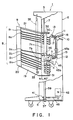
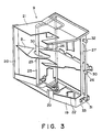
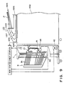
- the sorter 1 comprises a main assembly 6 including a couple of side plates 3, a base 5 and a cover 4.
- the sorter further comprises a bin unit 9 having a number of bins B and movable substantially vertically along guide rails 7 mounted on the respective side plates 3.
- the main assembly 6 of the sorter 1 is provided with a sheet inlet 10 for receiving sheets from a copying machine or the like, and a first sheet passage 11 is formed extending from the sheet inlet 10 toward the bin unit 9.
- a second sheet passage 12 is formed branching out of the first sheet passage 11. Downstream of the first sheet passage 11 with respect to the movement direction of the sheet, an upper discharging roller couple is disposed to discharge the sheets not to be sorted. Downstream of the second sheet passage 12, a roller discharging roller couple 15 is disposed to discharge the sheets to be sorted.
- a receiving roller couple 16 and a deflector 17 are provided at the branch between the first and second sheet passages 11 and 12.
- the deflector 17 is selectively displaceable either to direct the sheet discharged by the upper discharging roller couple 13 toward the bin B to the first sheet passage 11 or to direct the sheet discharged by the lower discharging couple 15 to the bin B to the second sheet passage 12.
- the bin unti 9 includes a bin supporting frame 19 having vertical portions 19a and a bottom portion 19b.
- the bin supporting frame 19 has a bin slider 20 mounted thereto at an end thereof, and the bin supporting frame 19 and the bin slider 20 are securedly fixed by a bin cover 21.
- a reference member 22 for alignment of the sheets is extended between and fixed to the bin cover 21 and the bottom portion 19b of the bin supporting frame 19.
- a swingable aligning rod 25 is extended through a cut-away portions 23 formed in all of the bins B. The sheets received by the bins B are abutted to the reference member 22 by the swinging movement of the aligning rod 25 to align the sheets.
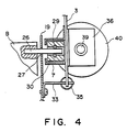
- Each of the bins B accommodated in the bin unit 9 is movably supported in a comb-like channels of a bin slider 20 at an end thereof, and at both sides at the base side thereof, it has pins 26 fixed thereto, as shown in Figure 4.
- the pin penetrates through a slit 27 formed in the bin supporting frame 19.
- a trunnion 30 is rotatably mounted through a cushion O-ring 29.
- the trunnions 30 of the bins B are stacked in the guide rail 7.
- the bottommost trunnion 30 is contacted to a lower guide roller 21 rotatably supported on the bin frame 19.
- the topmost trunnion 30 is contacted to the upper guide roller 32 rotatably supported on the bin supporting frame 19, so that each of the bins B is supported in the bin unit 9 with intervals between adjacent bins equal to the diameter of the trunnions 30.
- the upper guide roller 32 and the lower guide roller 31 are engaged with the guide rail 7, so that the bin unit 9 is movable substantially vertically.
- a spring 35 is stretched between a member 33 mounted to the bin supporting frame 19 of the bin unit 9 and a side plate 3 of the main assembly 6 of the sorter to normally urge the bin unit upwardly.
- a cam shaft holder 36 are mounted at a position corresponding to the above described lower discharging roller couple 15, as shown in Figure 1 and 2.
- a lead cam shaft 39 is rotatably mounted by means of a bearing 37.
- lead cams 40 and 40′ each having a helical cam surface is fixedly mounted.
- a sprocket 41 is fixedly mounted between the sprocket 41 and a shift motor 42, and a chain 43 is trained thereon, so that the lead cams 40 and 40′ are selectively rotated in a forward or a backward direction by selectively rotating the shift motor 42 in a forward or a backward rotation.
- the lead cams 40 and 40′ is disposed faced to the lower discharge couple 19 disposed substantially at the center of the main assembly 6 of the sorter, and functions to carry on its helical cam surface the trunnion 30 of a bin B moving toward the position faced to the lower discharging roller couple 15 to move it along the guide rail 7 in the vertical direction.
- an expanded space X which is larger than the intervals between other adjacent bins B is formed.
- the guide rail 7 formed in each of the side plates 3 has a configuration, as shown in Figures 1 and 5A and 5B, that is, it generally extends from the bottom to the top, and is bent away from the lower discharging roller couple 15 at a position faced to the lead cams 40 and 40′.
- the bin Ba When the trunnion 30 is introduced along the guide rail 7, the bin Ba, for example, is guided along the lower portion 7b of the guide rail 7 adjacent to the lower discharging roller couple 15 and receives the sheet P discharged from the lower discharge roller couple 15 without the trailing edge portion of the sheet P remained on the stopper B′. After it receives the sheet, it is moved upwardly along the rail (toward the upper portion 7a of the rail), avoiding the interference with the discharging roller couple 19, therefore, the sheet B accommodated thereon is not interfered with the lower discharging roller couple 15.
- the guiding means is so constructed that either of the trunnion not moved by the helical cam means and the trunnion moved by the helical cam means is shifted with respect to the other of them downwardly with respect to sheet discharge direction. Therefore, when the bin receives the sheet, it is close to the discharging means, whereas after it receives the sheet, it avoids the interference with the sheet discharging means by shifting downwardly, so that the sheet is prevented from being carried on the trailing edge stopper of the bin, or is prevented from jamming.
- a head of a stapler may be disposed at the shifting position, so that the head can be disposed without interference with the base portion of the bin, whereby the sheet sorter is easily equipped with a stapler.
- the lead cams 40 and 40′ are helical in different directions, as shown in Figures 5A and 5B.
- the lead cam 40 and the lead cam 40′ disposed at lateral sides provide driving forces in different directions.
- the cam configurations of the lead cams 40 and 40′ are such as to provide two (upper and lower) expanded portions X, simultaneously.
- the sheet being discharged through the lower discharging roller couple 15 is discharged to and is accommodated by the bin B faced to the lower discharging roller couple 15 through the upper expanded space X. Since the expanded spaces are simultaneously formed at two portions, the electric stapler unit 45 can be inserted for the bin B without an interference of the head 45a and the anvil 45b thereof unnecessarily interfering with the sheet ( Figure 1).
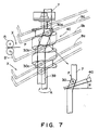
- Figure 8 shows a relationships between a left side lead cam 40 and the trunnion 30 driven by the lead cam 40.
- the bin Bb placed at the position faced to the lower discharging roller couple 15 and the trunnion 30b, as shown in Figure 7A, is moved by the lead cam 40 rotating in the direction of an arrow A from the position faced to the lower discharging roller couple 15 to the position of the trunnion 30a of the bin Ba shown in this Figure as an upper adjacent bin.
- a trunnion 30b receives from the lead cam 40 a force F ( Figure 7B) which is perpendicular to the inclination angle ⁇ of the helical cam surface of the lead cam 40, so that a large load is imposed to the trunnion 30b by the guide rail 7.
- Figure 8 also shows the relationships between the right hand lead cam 40′ and the trunnion 30.
- the trunnion 30b is moved by the lead cam 40′ rotatable in the direction indicated by an arrow A from a position opposed to the lower discharging roller couple 15 to the position of the trunnion 30a of the bin Ba shown as an upper bin in this Figure.
- the force F applied by the lead cam 40′ is substantially along the bending direction of the guide rail 7 ( Figure 5D), so that the load applied by the guide rail 7 is reduced, so that the trunnion 30 is very smoothly moved.
- the problem like this does not occur, since the lead cam 40 is rotated in the opposite rotational direction to the lead cam 40′, and the cam configuration is opposite to move the bins in the same directions at both of the lateral sides by the opposite direction rotations of the lead cams 40 and 40′.
- the bin B is inclined downwardly toward the sheet inlet side, and is moved with the space with the adjacent bin being increased and decreased in response to the vertical movement of the trunnion 30.
- a gap A is formed between the leading edge (the sheet inlet side) of the tray placed at a sheet receiving position and that of the bin thereabove, as seen from a direction substantially perpendicular to a sheet supporting surface of the bin.
- a similar gap is formed between the bin at the sheet receiving position and the bin below it.
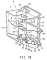
- a shaft 55 for swinging movement of the stapler extends substantially perpendicularly to the sheet supporting surface of the bin, so that the stapler 45 rotates in a plane substantially perpendicular to the sheet of the drawing of Figure 5B.
- the stapler head 45a of the stapler 45 approaches the top surface of the stack of the sheets on the bin through the gap from a lateral side of the bin, and simultaneously, the anvil 45b approaches toward the bottom side of the stack of the sheets through a space between the bins.
- the space between the adjacent bins is not required to be larger than the height of the stapler head 45a, and the stapling operation is possible with the relatively small space between the bins.
- the bin is further shifted substantially in the horizontal direction, a larger stapler head can be used.
- a sheet discharged from an image forming apparatus such as a copying apparatus is guided by a deflector 17 displaced on the basis of the selection between the non-sort mode and the sort mode, from the inlet selectively to the first sheet passage 11 or to the second sheet passage 12.
- the non-sort mode is selected, the sheet is transported along the first sheet passage 11 and is discharged to the first bin B1 of the bin unit 9 by the upper discharging roller couple 13.
- the trunnion 30 When the sort mode is selected, the trunnion 30 is sequentially moved by the helical cams of the lead cam 40 and 40′ which are rotating, to provide an expanded space between bins B faced to the lower discharging roller couple 15, which space is larger than the space between adjacent bins. During this movement, the moving trunnion 30 presses the upper guide roller 32 and the lower guide roller 31 to move the unit 9 as a whole. The sheet is discharged through the second sheet passage 12 by the lower discharge roller couple 15 to the first bin B1, and then discharged to the bin B2.
- the bins Ba, Bb and Bc moved to the neighborhood of the lower discharging roller couple 15 is moved along the guide rail 7 with the trunnions 30a, 30b and 30c carried on the helical cam surface of the lead cam 40. Between the bins Ba, Bb and Bc, expanded spaces X and X which are larger than the interval between the other adjacent bins is formed.
- the bin Bb having received the sheet discharged by the lower discharging roller couple 15 is moved to the position of the upper bin Ba, avoiding the lower discharging roller couple 15, with the trunnion 30b being moved along the bent guide rail 7 by the lead cam 40 rotating in the direction indicated by an arrow D and a lead cam 40′ rotating in the direction indicated by an arrow A by the rotation of the shift motor 42.
- the accommodating bin Bb moved close to the lower discharging roller couple 15 so as to assuredly receive the sheet P discharged by the lower discharging roller couple 15, is moved along the bent guide rail 7, so that it is not interfered with the lower discharging roller couple 15 after the sheet is accommodated.
- the trunnion 30b When the trunnion 30b is moved along the bent portion of the guide rail 7, the trunnion 30b receives the force F from each of the lead cams 40 and 40′, which is substantially along the bending direction of the guide rail 7 ( Figures 5C and 5D). As a result, the bin B is efficiently moved, so that the load to the shift motor 42 is small, and also, the vibration of the bin B is small, and therefore, the sheets aligned on the bin B is not disturbed without production of noise.
- an image forming unit 1101 includes a copying apparatus 1102, an automatic original or document feeder 1103 disposed above the copying machine 1102 and a sheet sorter disposed at one side of the copying machine 1102.
- Documents or originals P placed on an original stacking tray 1105 of the automatic document feeder 1103 are separated in order from the bottom, and are fed one by one through a passage 1107 onto the platen glass 1106 of the copying machine 1102.
- the original is read by an optical system of the copying machine 1102. After it is read, it is returned from on the platen glass 1106 to the topmost of the original stacking tray 1105.
- a sheet S having received an image of the original P transferred thereto is discharged to the sorter 1 depending on the number of copies to be taken, the selection of mode from the sort mode and non-sort mode or the like.
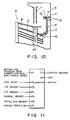
- the sorter 1 is provided with a non-sort stapling controller 1046 for stapling non-sorted sheets.
- the controller 1046 is effective to control the above-described bin unit 9 and the electric stapler 49 when the sheets S are discharged onto the first bin B1 from the upper discharging roller couple 13 in the non-sort mode.
- the controller 1046 causes movement of the bin unit 9 so that the first bin B1 accommodating the sheets S is faced to the lower discharging roller couple 15, as shown in Figure 10, and causes the electric stapler 45 to perform the stapling operation to the sheets S on the first bin B1 now faced to the lower discharging roller couple 15.
- a reference numeral 1047 in Figure 9 designates a manual stapling switch.
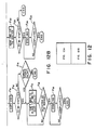
- Originals P are placed on the automatic document feeder 1103 (F1). Then, the operator inputs into the copying machine 1102 a copying mode, a number to be copied, sort or non-sort mode selection and stapling or non-stapling mode selection (F2). When a copy start switch is actuated (F3), the copying machine discriminates the copying mode (a simplex copy, for example) and the sorter 1 discriminates whether the sort mode or non-sort mode is selected (F4).
- a copy start switch is actuated (F3)
- the copying machine discriminates the copying mode (a simplex copy, for example) and the sorter 1 discriminates whether the sort mode or non-sort mode is selected (F4).
- the solenoid is actuated (F5) to shift the deflector 17 of the sorter 1 to direct the sheet (transfer sheet) S to the first sheet passage 11.
- the bin unit 9 is moved until the first bin B1 is opposed to the upper discharging roller couple 13 (F6).
- the bin unit 9 is provided with a flag on the bin supporting frame 19 at this position, so that when the bin unit 9 moves to such an extent that the first bin B1 reaches this position, an unshown second sensor detects the flag.
- the number of copies to be taken is single in the non-sort mode, and the following description will be made in this case with the stapling mode selected.
- the copying machine 1102 In response to detection signal from the second sensor (F7), the copying machine 1102 starts the copying operation (F8). Then, the originals P are sequentially fed from the automatic document feeder 1103, and the sheets S are discharged onto the first bin B1 until a document feeder empty signal is transmitted to a controlling station of the copying machine 1102. After the signal is received by the controlling station, the copying operation to the last original P is completed (F9). Then, the sorter 1 receives a copy completion signal. The description is made as to whether the sheets S are to be stapled or not (F16).
- the bin unit 9 When the stapling mode is selected, the bin unit 9 is moved after the last sheet S is received, until the first bin B1 is faced to the stapling position adjacent to the lower discharging roller couple 15 (F11).
- the position of the first bin B1 in this stapling position is the same as the position of the first bin B1 faced to the lower discharging roller couple 15 to receive the sheets in the sort mode ( Figure 5), and the first sensor corresponding to this position detects the flag of the bin supporting frame 19 (F12) to control the bin position.
- the electric stapler 45 operates (F13) to staple the sheets S which have been discharged by the upper discharging roller couple 13 and have been accommodated on the first bin B1.
- the manual stapling switch 1047 shown in Figure 9 is actuated (F14).
- the bin unit 9 moves until the first bin B1 reaches the position corresponding to the stapling position, and thereafter, the stapling operation is effected in the similar manner (F13).
- the bin unit 9 is moved so that the first bin B1 is placed opposed to the lower discharging roller couple 15 to receive the sheets S on the first bin B1 (F17). This position is detected by the first sensor in the manner similar to described above (F18). After the movement of the bins, copy start permitting signal is produced (F19), in response to which operations of the copying machine 1102 and the sorter 1 start (F20).
- the sheets S corresponding to the originals P are continued to be discharged until no-document signal is transmitted to the controlling station of the copying machine 1102, and the sheets are sorted and accommodated on the number of bins equal to the number of copies to be taken.
- the copying operation to the last original is completed (F21).
- the sorter 1 receives the copy completion signal (F22).
- the controlling station discriminates whether the stapling mode is selected or not (F23). When the stapling mode is selected, the stapling operation starts with the bin which has received the last sheet (F24). After the completion of the stapling for the bin B, the sheets S on the next bin are stapled.
- the stapling completion signal is produced, and the electric stapler 45 stops (F25). If the stapling mode is not selected at the initial mode setting, but the stapling is wanted after the sheets are sorted and discharged, the operator actuates the manual stapling switch 1047 after the sheets are accommodated, similarly to the case of the non-sort mode. In response to the signal indicative of this, the stapling operation starts with the bin having received the last sheet.
- the bin is moved to a position corresponding to the first sheet passage 11 to make it easier for the operator to take the sheet out.
- the image forming unit 1101 is operated under the control of a control circuit shown in Figure 11 which is self explanatory.
- the stapling means is disposed to the sheet discharging means for discharging the sheet to be sorted; when the stapling is wanted when the sheets are not to be sorted, the bin for receiving the non-sorted sheet opposed to the sheet discharging means for the non-sorted sheets is moved to a position for opposing to the sheet discharging means for discharging the sheet to be sorted, and the sheets thereon are sorted by the same stapling means, by the non-sort sheet stapling controller. Therefore, the non-sorted sheets are moved to a position opposing to the sheet discharging means to which the stapling means is disposed, so that the non-sorted sheets can be stapled.
- a supporting frame 123 is fixed to the left side of the base portion of the bin frame 19.
- a rotation shaft 127 having an upper end fixed to an upper arm 125 and a lower end fixed to the lower arm 125 is rotatably mounted by an unshown rotational shaft mounted on the supporting plate 123 and by a rotational shaft 129 mounted on the bin cover 21.
- a sector gear 131 is rotatably supported about a rotational shaft mounted on the supporting plate 123, and said lower arm 126 is fixed to the sector gear.
- a pulse motor 123 is disposed below the supporting plate.
- a gear 133 fixed to the output shaft of the pulse motor 132 is meshed with the sector gear 131.
- An aligning rod 25 is extended between an end of the lower arm 126 and an end of the upper arm 125 and is penetrated through a cut-away portion 23 formed in all of the bins.
- the aligning rod 25 is swingable by the rotation of the sector gear 131.
- the lower arm 126 is provided with a light blocking point 137, which rotates integrally with the lower arm 126, whereby a home position sensor 139 disposed at the left side of the bin frame 19 is actuated.
- Each of the bins B accommodated in the bin unit 9 is provided with trunnions 30 at the longitudinal base side ends.
- the trunnions are projected through slits formed in the vertical portions 19a of the bin frame of the trunnion 30 and are engaged with and stacked in the guide rails 7 ( Figure 14), in this embodiment, the guide rail 7 extending straight in the vertical direction.
- the bottommost trunnion 30 is in contact with the lower guide roller 31 rotatably supported on the vertical portion 19a of the bin frame 19, whereas the topmost trunnion is contacted to an upper guide roller 32 rotatably supported on the vertical portion 19a of the bin frame 19. Therefore, the bin B are supported in the bin unit 9 with the intervals therebetween equal to the diameter of the trunnions 30.
- the bin unit 9 is movable vertically along the guide rail with the upper guide roller 32 and lower guide roller 31 engaged with the guide rails 7.
- an electric stapler 45 for stapling the sheets accommodated on the bin B Adjacent to the lower discharging roller couple 15, an electric stapler 45 for stapling the sheets accommodated on the bin B is disposed, which is provided with a solenoid 156 and a stapler spring 157.
- the electric stapler 45 is rotatable about a pivot 159, and is normally abutted to a stopper 160 to take a retracted position (solid line position) outside the sheet path.
- solid line position solid line position
- a microswitch 161 shown in Figure 16 serves to detect the electric stapler 45 moved to the sheet stapling position.
- the sheet S discharged from the image forming apparatus such as a copying machine is selectively directed to the first sheet passage 11 or to the second sheet passage 12 by the deflector 17 from the sheet inlet 10, depending on the mode selected from the non-sort mode and the sort mode.
- the sheet is discharged to and received by the first bin B1 of the bin unit 9 by the upper discharging roller couple 13 through the first sheet passage 11.
- the lead cam 40 rotates to sequentially move the trunnions 30 by the helical cam thereof to provide two expanded portion X and X with the bin B opposed to the lower discharging roller couple 15, the expanded portion being larger than the space between the other adjacent bins.
- the upper guide roller 43 or the lower guide roller 42 is urged so that the bin unit 9 moves as a whole.
- the sheets S are discharged sequentially by the lower discharging roller couple 15 through the second sheet passage 12 and are received by the first bin B1 and the subsequent bins sequentially.
- the aligning rod 25 is moved from its retracted position 25′ through a predetermined distance in the direction indicated by an arrow E by a pulse motor 132 rotated in accordance with a pulse signal corresponding to the size of the sheet, by which a lateral edge of the sheet S is abutted to an alignment reference member 122.
- the aligning rod 25 is returned to the retracted position to be prepared for the next sheet discharge, after it moves through the predetermined distance.
- a plurality of sheets S are accommodated on a bin Bb with its lateral edge aligned to the alignment reference member 122 and with its trailing edge aligned to the trailing edge stopper B′.
- the aligning rod 25 penetrates through all the bins B, and therefore, the sheets S received by the other bins B are similarly aligned.
- the sheets S discharged to and accommodated by the bins are stapled. If the stapling mode is not selected, the operation of the sorter 1 terminated here.
- the solenoid 156 is actuated by a stapling start signal, by which the electric stapler 45 is pulled by the solenoid 156 to rotate about a pivot 159 to the stapling position indicated by solid lines in Figure 17.
- the head 45a of the electric stapler 45 advances to the stapling position through an upper expanded space X formed between the bin Bb accommodating the sheets to be stapled and the upper adjacent bin Ba, as shown in Figure 15, whereas the anvil 45b is moved to the stapling position through the lower expanded portion X.
- the microswitch 161 When the electric stapler 45 moves to the stapling position, the microswitch 161 is actuated to produce a permitting signal, in response to which the electric stapler 45 is actuated to staple the sheets S by a staple 162.
- the solenoid 156 is deenergized so that the electric stapler 45 is returned to a position abutting to the stopper 160 by the stapler spring 157. This is the end of the stapling operation.
- the stapling operations for plural bins, it is most efficient to start the stapling operation with the last bin B which has received the last discharged sheet.
- the above-described series of operations start in response to a signal indicative of completion of the bin shifting operation; then, the next bin shifting operation starts in response to a signal indicative of completion of the series of operations of the electric stapler 45.
- the number of bin shifting operation is equal to the number of the bin shifting operations during the sorting operation.
- the bin frame 19 of the bin unit 9 is provided with the alignment reference member 122, and also, the bin unit 9 is provided with a sheet aligning unit including an aligning rod 25, and therefore, the sheets S on the bins B can be aligned with certainty.
- the sheets S can be aligned by the movement of the aligning rod 25 even during the bin shifting operation as well as immediately after the sheet is discharged on a bin B. In other words, the sheets S can be aligned at any time other than during the sheet S being in the process of discharge.
- the aligning rod 25 is moved by rotation about the rotational shaft 129 in this embodiment, and the rotational shaft 129 and the alignment reference member 122 are integral with the bin unit 9, wherefore the sheets can be aligned always stably.
- the head 45a and the anvil 45b of the electric stapler 45 are easily displaced to the respective stapling positions at the time of stapling operation, and in addition, the sheets can be stapled assuredly without interference with the sheets S accommodated on the lower bin B.
- the aligning rod 25 and the electric stapler 45 are swingable about respective pivots, but one or both of them may be rectilinearly moved.
- a part of front side of the bin frame 19 is formed into a sheet alignment reference 19c, in place of the alignment reference member 122 in the foregoing embodiment. Since the alignment reference 19c and the bin frame 19 are integral, the sheet alignment reference 19c can be extended to the neighborhood of the stapler 45, as will be understood by a reference 19c′, so that the width of the sheet alignment reference 19c can be increased to make possible a more stabilized sheet aligning operation.
- An elongated slot 272 is formed in each of the bins B which is slidably engaged with an end side shaft 271 fixed to the bin slider 20 of the bin unit 9.
- An arm lever 275 is rotatably mounted on each of base side shafts 273 securedly fixed to the bin frame 219.
- a trunnion 230 is rotatably mounted by a pin 277.
- a pin 279 is mounted, which pin is engaged with a hole of the bin B.
- a stationary cam plate 290 is fixedly mounted to each of the side plates of the sorter to guide the trunnions 230.
- the trunnion 230b of the second bin Bb contacted to a first cam surface 290a of the cam plate 290 rotates downwardly about the pin 273b, so that the bin Bb moves substantially parallel to a direction indicated by a reference G to provide expanded space between the lower third bin Bc.
- the use is made with a Geneva pulley 391 having slots 392 engageable with the trunnions 330 of the bins B to form two expanded spaces between bins, simultaneously.
- the pulley 391 has four engaging slots 392 engageable with trunnions 330.
- a trunnion 330 of a bin Bc for example, is engaged with a slit 392c of the pulley 391, and it moves upwardly along the guiding slot 393 by the rotation of the pulley 391 to a position indicated by a reference 330b, where it is stopped.
- the trunnion 330b of the upper bin Bb placed at the position 330b is moved upwardly to the upper position 330a. In this manner, expanded spaces X and X are formed between the intermediate bin Bb and the upper bin Ba, and between the intermediate bin Bb and the lower bin Bc.
- the trunnions 330 are rotatably mounted to the respective bins B and are stacked in the guiding slot 393.
- the bottommost trunnion 30 is urged upwardly by the spring.
- the bin 410 is provided with engaging plates 446 at front and free end side and at the rear free end side, respectively.
- the engaging plate 446 engages an unshown supporting plate disposed inside the frame 20 to support the free end side of the bin 110.
- the bin 410 is further provided with supporting shafts 26 at the front base side and the rear base side thereof, respectively. Each of the supporting shaft 26 has a roller 30 rotatably mounted thereto.
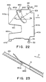
- the bin 410 has an elongated slot 450 extending a predetermined distance (L) away from the shaft 129.
- the slot 450 has such a length as is longer than the rotational distance through which the alignment rod 125 is movable and has a width sufficiently larger than the diameter of the alignment rod 125 (minimum width is l ).
- the downstream surface of the slot 450 with respect to the sheet discharging direction A is tapered 451a ( Figure 23).
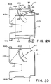
- the corner portion 410a of the bin 410 at the free end and rear side is inclined at a predetermined angle with respect to a sheet supporting surface 410b.
- the base side 410c is extending perpendicularly to the sheet supporting surface 410b.
- the bin 410 itself is inclined upwardly toward the free end. By this inclination, the sheet is aligned in the sheet conveying direction by the sheet sliding on the sheet supporting surface 410b so that its trailing edge abuts the perpendicular portion 410c.
- a cut-away portion 451b is formed extending from the free end of the bin 451 generally to the center of the sheet supporting surface 410b to facilitate the operator to take out small size sheets stacked on the sheet supporting surface 410b.
- the sheet S discharged from an image forming apparatus after being subjected to an image forming operation is discharged to the topmost bin by the discharging roller couple 15 through the passage 12.
- the leading edge of the sheet S passes above the elongated slot 450, but the leading edge of the sheet S is not obstructed by the elongated slot 450 because it is guided by the taper 451a ( Figure 23).
- the sheet S discharged on the bin slides on the bin 151 to abut the base perpendicular portion 410c by the inclination of the bin.
- the sheet S is still away from the alignment reference plate 122, as shown by chain lines in Figure 24.
- the pulse motor 135 rotates through a rotational angle determined in accordance with information from the image forming apparatus indicative of the sheet size, so that the alignment rod 25 moves from the home position H in the direction indicated by an arrow in the elongated slot 450, thus moving the sheet S from the chain line position to the solid line position, whereby the sheet S is abutted to and aligned with the alignment reference plate 122 ( Figure 24).
- the pulse motor 135 is reversed to return the alignment rod 142 to the home position H.
- the elongated slot 450 is formed at a predetermined distance (L) away from the shaft 129 (radius L) with a minimum width l .
- the slots 450′ may be formed by circumferences having a radius L and (L + l ) about a shaft 129.
- the portion around the periphery of the elongated slot 450 of the bin 451 may be made thicker with smooth inclination to form a thick portion 451b.
- the bin 451 is reinforced, and the sheet S discharged onto the bin is guided upwardly by the thick portion 451b to prevent the sheet S from being obstructed by the elongated slot 450.
- the alignment rod 25 is rotated, but as shown in Figure 28, it (aligning rod 425) may be made movable along a rectilinear line.
- the elongated slot 450′′ is extended straight, by which the contact portion between the elongated slot 450′′ and the sheet S is reduced, therefore, the obstruction by the slot 450′′ to the sheet movement S is further prevented.
- the bin is provided with the elongated slot for allowing penetration of alignment member, so that the alignment member moves through the slot to perform the sheet aligning operation, by which the necessity of the provision of an open slot for allowing insertion of the alignment member is eliminated, so that the strength of the bin can be assured.
- the possibility that the sheet is obstructed by the slot resulting in inability of the alignment can be reduced.
- the sheet aligning operation by the aligning member 442 can be performed without obstruction. More particularly, even if there is a cut-away portion 451b for allowing small size sheets to be taken out, the inclined surface 410a is effective to keep the sheets with a certain degree of rigidity when large size sheets are supported on the sheet supporting surface 410b to prevent the sheets to be flexed; and despite the fact, the inclined portion is not formed at the alignment reference plate 121 side.
- tapered surface 451a at the downstream side of the elongated slot 450 with respect to the sheet discharging direction, the sheet is prevented from being obstructed by the elongated slot 450 when it is being discharged, so that the sheet can be assuredly received on the bin 451.
- the strength of the bin about the elongated slot 450 can be increased.
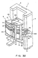
- the stapler 560 includes a driving motor 561, a gear 562 fixed to an output shaft of the motor 561, wherein a gear 563 is meshed with the gear 562.
- the gear 563 is connected with a link 565 having an end mounted to the frame of the apparatus.
- a stapling head 566 is disposed at an articulation 565a of the link 565.
- anvil 567 is disposed below the stapling head 566.
- the stapler 560 is fixedly mounted on a stapler base 561 fixed on a swingable base 570 which is swingable about a shaft 569, so that it is movable swingingly together with the swingable base 570.
- the swingable base 570 is provided through the mounting base 572 with a sheet detecting sensor 573 for detecting presence and absence of the sheet adjacent a front and right corner of the stapler 560.
- the sensor block 573 comprises a light emitting portion 573a and a light receiving portion 573b and is in the form of a channel.
- the swingable base 570 is rotated by an unshown motor to move the stapler 560 from a normal retracted position A to the stapling position B by the rotation about the shaft 569.
- the trailing and front corner of the sheet S on the bin B relatively passes across the space between the light emitting portion 573a and the light receiving portion 573b of the sheet sensor 573 which swings together with the swinging motion of the swingable base 570, by which the sheet S is detected by the sensor block 573. If the sheets S on the bin B have in advertently taken out so that the sensor block 573 does not detect any sheet, the microcomputer 561 prevents the stapling action by the stapler 560 and returns it to the retracted position A.
- the microcomputer When the microcomputer receives a signal indicative of the presence of the sheet S by the sensor block 573, it drives the motor 561 to allow the stapler 560 to staple the sheets S on the bin B. After the stapling action, the stapler 560 is returned to its retracted position A.
- the microcomputer rotates the lead cam 40 by the driving motor 42 to lift the bins through one stage, and after the sheet sensor block 573 detects the presence of the sheet S accommodated on the second bin B, the stapler 560 now disposed for the second bin performs the stapling action.
- the bins B are lifted step by step, and sets of the sheets S on the bins B are sequentially detected by the sheet sensor block 573, and is stapled. When all of the sets of the sheets S on the bin B are stapled, the stapling operation is stopped.
- the stapling operation was performed after completion of the sorting and accommodation of the sheets S, but it is a possible alternative that a set of sheets S is stapled each time the final sheet S is discharged on the bin.
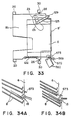
- a transparent type sensor movable together with the stapler 560 is used for the sheet detecting sensor block 573, but it is a possible alternative that a reflecting type sensor fixedly mounted to the frame 6 may be used, as shown in Figure 34A. If this is used, mounting of the sensor 673 is easy if the sorter 1 is of the type wherein the bins 110 are movable horizontally (sheet discharging direction), as shown in Figure 34B.
- the sheet sensor 673 is movable integrally with the stapler 560, but the sensor 673 may be independently rotatable.
- the sheet sensor block 573 is mounted to the swingable base 570 through the mounting base 572, but the light emitting portion 573a and the light receiving portion 573b of the sheet sensor 573 may be mounted to the head 566 and the anvil 567 of the stapler, respectively.
- detecting means for detecting the sheets accommodated on the bin on which the stapler acts, and the stapling operation is allowed only when the detecting means detects the sheet on the bin, and therefore, the stapler is prevented from performing the stapling action without sheets, which can result in jam of staples.
- the detecting means By mounting the detecting means on the stapling device, it is possible to detect presence or absence of the sheets to be stapled during the stapler moving to the stapling position, whereby particular time is not required for the detection. Therefore, the post processing operation can be speedily and efficiently performed.
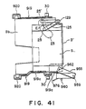
- the frame 6a has a shaft 569 mounted thereon, on which a swingable base 570 is rotatably supported.
- the swingable base 570 has a stapler base 571 fixedly mounted thereto.
- the stapler base 571 carried a stapler 560.
- a gear box G containing reduction gears 675 is mounted, and to the gear box G a motor 676 is mounted.
- the motor 676 has an output shaft to which a gear 677 is fixedly mounted.
- the gear 677 is meshed with an input gear 675a of the gear train 675.
- the gear train 675 has an output shaft 675b to which a link disk 679 is mounted.
- cams 679a and 679b are disposed, and they serve to actuate or deactuate a microswitch 680 which is mounted on the frame 6a to energize the motor 676.
- a shaft 679c Adjacent the outer periphery of the disk 679, a shaft 679c is mounted.
- a link arm 681 is connected for rotation in a horizontal plane.
- the link arm 681 is provided with a shaft 681 and has an elongated slot 681b. Through the slot 681b, the shaft 679c is penetrated, and a spring 682 is stretched between the shaft 379c and the shaft 681a.
- a bell crank arm 683 made of resin material or the like is rotatably supported.
- An end 683a of the arm 683 is contacted to an end 570a of the swingable base 570, and the other end 683b is contactable to a microswitch 685 for detecting the stapler being displaced at its stapling position.
- a sheet sensor block 573 for detecting presence and absence of the sheet is mounted through a mounting base 572 ( Figure 29).
- the sensor block 573 comprises a transparent type sensor having a channel shape and comprising a light emitting portion 573a and a light receiving portion 573b.
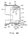
- the microcomputer drives the driving motor 42 to rotate the lead cam 40 to place the topmost bin to the stapling position, that is, the position for receiving a sheet S discharged by the discharging roller couple 15. Then, the computer instructs the motor 376 to rotate, and the rotation of the motor 676 is reduced by the gear train 675 and is transmitted to the output shaft 675b. By this, the link disk 679 rotates in the clockwise direction.
- the stapler 560 is at its retracted position A ( Figure 29)
- the cam portion 679b is in contact with the microswitch 680 to close it.
- the swingable base 570 is at a position shown in Figure 36.
- An end 570a of the base 570 ( Figure 36) pushes an end 683a of the arm 683 to rotate the arm 683 in the counter-clockwise direction.
- the other end 683b of the arm 683 presses the microswitch 385 to actuate the switch 685.
- the microcomputer receives the on-signal of the switch 685 to detect the stapler 560 having moved to the stapling position B ( Figure 36).
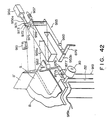
- the stapler 560 moves from the retracted position A to the stapling position B, the sheets S accommodated on the bin are guided by upper and lower guides 574 and 674 into the space between the head 566 of the stapler 560 and the anvil 567.
- the set of sheets S is detected by the sensor block 573 by the trailing end front corner of the sheets S on the bin 110 passing through the space between the light emitting portion 573 and the light receiving portion 573b of the sheet sensor block 573 which integrally moving with the swingable base 570. If the sensor block 573 does not detect the sheets S for the reason, for example, that the sheets S have been inadvertently taken out from the bin by the operator, the microcomputer does not allow the stapler 560 to operate but causes it to be returned to the retracted position A.
- the microcomputer 561 When the microcomputer 561 receives the signal indicative of the presence of the sheet S by the sensor block 573, it instructs to drive the driving motor 661 to make the stapler 560 staple the sheets S on the bin. After the stapling operation, the stapler 560 is returned to the retracted position A.
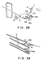
- the sheet sensor block 573 is in the form of a channel and has generally a rectangular cross section. It is a possible alternative that, as shown in Figures 37A and 37B, a tapered surface 573c is formed, wherein an upper guide 686 is provided on the same surface as the aforementioned upper guide 674, and a lower guide 687 is provided on the same surface as the aforementioned lower guide 674.
- an upper guide 686 is provided on the same surface as the aforementioned upper guide 674
- a lower guide 687 is provided on the same surface as the aforementioned lower guide 674.
- the curled sheet confining member 789 includes a gear 790 connected to an unshown motor, a gear 791 meshed with the gear 790 and a curled sheet confining rod 793 fixed to a shaft 792 of the gear 791.
- the rod 793 swings to confine the curled sheet.
- the upper and lower guides 574 and 674 are used for confining the curled sheet.
- a sheet confining spring 895 constituted by a leaf spring or the like is provided at a base side of each of the bins B. The curled sheet is confined by the confining spring 895 mounted to the adjacent upper bin B.
- a curl confining means to confine the curled sheet which is going to be stapled by the stapler, by which the sheet is prevented from being contacted by the stapler and being folded or being disturbed, which can result in improper stapling.
- an automatic (electric) stapler 955 for stapling the sheets accommodated in each of the bins B, facing a lower couple of discharging rollers 15.
- the automatic stapler 955 includes a solenoid 956 and a stapling spring 957.
- the solenoid 956 has a link 956a to which a link pin 971 is fixedly mounted, and a solenoid spring 973 is stretched between the link pin 971 and a stapler pin 972 of the automatic stapler 955.
- the link 956a is engaged with the stapler pin 972 through a slot formed in an end portion of the link 956a.
- a stapling position stopper 976 is fixedly mounted, and the stapler 955 is normally placed outside the path for the sheet (solid line position) by being contacted to the stopper 906 by the function of the stapler spring 957.
- the solenoid 956 is operated to move the stapler to the position shown by chain lines where the stapling position stopper 976 is abutted to a sheet alignment reference 919c of the bin frame 919. Then, the sheets S accommodated in the bin B opposed to the lower couple of the discharging rollers 15.
- a microswitch to detect the stapler 955 placed at the stapling position to produce a detection signal.
- the solenoid 956 is actuated in response to a stapling start signal.
- the automatic stapler 955 rotatingly moves about a pivot 959 by the solenoid 956 and is moved to its stapling position so that the stapling position stopper 976 is abutted to the sheet alignment reference position 919c, by which the stapler 955 is correctly positioned.
- the head portion 955a of the stapler 955 moves to the stapling position through an upper opening portion X formed between the bin Bb accommodating the sheets to be stapled and the adjacent upper bin Ba, and the anvil portion 955b is moved to the stapling position through a lower opening X, that is the opening formed between the bin Bb and the adjacent lower bin.
- the microswitch 961 is actuated, so that a stapling permitting signal is produced, in response to which the stapler 955 is driven, by which the sheets S are stapled by staple 962.
- solenoid 956 is deactuated, and the stapler 955 is returned by the function of the stapler spring 957 to be contacted to the stopper 960.
- the stapling operation for one bin terminates.
- the stapling operation starts from the last bin B to which the sheet is lastly discharged.
- the bin is shifted in response to a signal indicative of completion of the series of the stapler 955 operations; and these are repeated until the stapling operation is effected for each of the bins.
- the number of the bin shifts for the automatic stapling corresponds to the number of bin shifts at the time of the sorting operation.
- a frame guide 877 for guiding the bin frame 919 is disposed at the front side of the sorter 6, and an end of a bin frame 919 is slidably engaged in a guiding groove 877a of the frame guide 877.
- the automatic stapler 955 has a stapling position stopper 876 fixedly mounted thereto, which abuts the frame guide 877 to position automatic stapler 955 at its stapling position when it is moved to the stapling position.
- the stapler 955 is moved to the stapling position and is abutted to and positioned by the frame guide 877 for guiding and positioning the sheet alignment reference 919c, so that the sheet accommodated in the bin B is stapled.
- the sorter has vertically movable bins, wherein the stapler is positioned and rotatable at a predetermined level.
- the sorter may be of a stationary bin type, and the stapler may be of an elevatable type.
- a sheet alignment reference member which functions as a reference for aligning the sheets, and a portion substantially integral with the sheet alignment reference member functions as means for positioning the stapler at the stapling position, whereby the stapling position of the stapler can be correctly determined relative to the sheets, and therefore the sheets can be correctly and assuredly stapled.
Landscapes
- Engineering & Computer Science (AREA)
- Mechanical Engineering (AREA)
- Physics & Mathematics (AREA)
- General Physics & Mathematics (AREA)
- Textile Engineering (AREA)
- Collation Of Sheets And Webs (AREA)
Applications Claiming Priority (14)
| Application Number | Priority Date | Filing Date | Title |
|---|---|---|---|
| JP62191936A JPH0633009B2 (ja) | 1987-07-30 | 1987-07-30 | シ−ト後処理装置 |
| JP191937/87 | 1987-07-30 | ||
| JP191934/87 | 1987-07-30 | ||
| JP191936/87 | 1987-07-30 | ||
| JP62191938A JPH0637119B2 (ja) | 1987-07-30 | 1987-07-30 | シ−ト分類装置 |
| JP62191934A JPH0774063B2 (ja) | 1987-07-30 | 1987-07-30 | シ−ト後処理装置 |
| JP62191937A JP2575724B2 (ja) | 1987-07-30 | 1987-07-30 | シ−ト分類装置 |
| JP191938/87 | 1987-07-30 | ||
| JP62197786A JPH0635221B2 (ja) | 1987-08-07 | 1987-08-07 | シ−ト分類装置 |
| JP197786/87 | 1987-08-07 | ||
| JP62200289A JPH0635219B2 (ja) | 1987-08-10 | 1987-08-10 | シ−ト分類装置 |
| JP200288/87 | 1987-08-10 | ||
| JP200289/87 | 1987-08-10 | ||
| JP62200288A JPS6443456A (en) | 1987-08-10 | 1987-08-10 | Sheet post-processor |
Publications (3)
| Publication Number | Publication Date |
|---|---|
| EP0301595A2 true EP0301595A2 (de) | 1989-02-01 |
| EP0301595A3 EP0301595A3 (de) | 1991-01-16 |
| EP0301595B1 EP0301595B1 (de) | 1994-12-07 |
Family
ID=27566448
Family Applications (4)
| Application Number | Title | Priority Date | Filing Date |
|---|---|---|---|
| EP94114777A Expired - Lifetime EP0631201B1 (de) | 1987-07-30 | 1988-07-29 | Sortiervorrichtung für blattförmiges Material |
| EP88112386A Expired - Lifetime EP0301594B1 (de) | 1987-07-30 | 1988-07-29 | Mit einer Heftvorrichtung versehenes Blattsortiergerät |
| EP88112388A Expired - Lifetime EP0301596B1 (de) | 1987-07-30 | 1988-07-29 | Mit einer Heftvorrichtung versehenes Blattsortiergerät |
| EP88112387A Expired - Lifetime EP0301595B1 (de) | 1987-07-30 | 1988-07-29 | Kontrollverfahren für ein Sortiergerät mit einer Heftvorrichtung |
Family Applications Before (3)
| Application Number | Title | Priority Date | Filing Date |
|---|---|---|---|
| EP94114777A Expired - Lifetime EP0631201B1 (de) | 1987-07-30 | 1988-07-29 | Sortiervorrichtung für blattförmiges Material |
| EP88112386A Expired - Lifetime EP0301594B1 (de) | 1987-07-30 | 1988-07-29 | Mit einer Heftvorrichtung versehenes Blattsortiergerät |
| EP88112388A Expired - Lifetime EP0301596B1 (de) | 1987-07-30 | 1988-07-29 | Mit einer Heftvorrichtung versehenes Blattsortiergerät |
Country Status (3)
| Country | Link |
|---|---|
| US (2) | US4986520A (de) |
| EP (4) | EP0631201B1 (de) |
| DE (4) | DE3855374T2 (de) |
Cited By (9)
| Publication number | Priority date | Publication date | Assignee | Title |
|---|---|---|---|---|
| US5024430A (en) * | 1989-01-18 | 1991-06-18 | Ricoh Company, Ltd. | Paper handling apparatus |
| EP0437646A1 (de) * | 1990-01-15 | 1991-07-24 | Ikegami Tsushinki Co., Ltd. | Sortiermaschine |
| US5090673A (en) * | 1989-09-05 | 1992-02-25 | Canon Kabushiki Kaisha & Canon Aptex, Inc. | Sheet post treatment apparatus |
| US5112035A (en) * | 1990-01-16 | 1992-05-12 | Ikegami Tsushinki Co., Ltd. | Sorter |
| US5131642A (en) * | 1989-10-31 | 1992-07-21 | Ikegami Tsushinki Co., Ltd. | Sorter |
| EP0522462A2 (de) * | 1991-07-06 | 1993-01-13 | Canon Kabushiki Kaisha | Blattsortiergerät |
| EP0588340A2 (de) * | 1992-09-17 | 1994-03-23 | Canon Kabushiki Kaisha | Vorrichtung zum Handhaben von Papierblättern und diese Vorrichtung benutzendes Bilderzeugungsgerät |
| EP0624538A2 (de) * | 1989-10-18 | 1994-11-17 | Canon Kabushiki Kaisha | Blattsortiervorrichtung |
| CN105858313A (zh) * | 2016-06-01 | 2016-08-17 | 成都超天硕科技有限公司 | 一种使用方便的纸张托盘装置及其使用方法 |
Families Citing this family (38)
| Publication number | Priority date | Publication date | Assignee | Title |
|---|---|---|---|---|
| US5382016A (en) * | 1988-03-11 | 1995-01-17 | Canon Kabushiki Kaisha | Sheet sorter with a stapler having a controlled sheet aligning member |
| US5031890A (en) * | 1989-01-19 | 1991-07-16 | Ricoh Company, Ltd. | Paper handling apparatus |
| US5064181A (en) * | 1989-01-19 | 1991-11-12 | Ricoh Company, Ltd. | Paper handling apparatus |
| JPH03143691A (ja) * | 1989-10-31 | 1991-06-19 | Ikegami Tsushinki Co Ltd | スティプラ付ソータ |
| US5140380A (en) * | 1989-11-09 | 1992-08-18 | Canon Kabushiki Kaisha | Image forming apparatus with book binding mechanism |
| KR920004353B1 (ko) * | 1990-01-25 | 1992-06-04 | 주식회사 신도리코 | 콤팩트소터(Compact Sorter) |
| US5265855A (en) * | 1990-04-17 | 1993-11-30 | Ricoh Company, Ltd. | Copier with document support moving means |
| JP2760140B2 (ja) * | 1990-06-23 | 1998-05-28 | ミノルタ株式会社 | ソータ |
| JP3080429B2 (ja) * | 1990-06-29 | 2000-08-28 | 株式会社リコー | 紙処理装置 |
| US5110102A (en) * | 1990-07-10 | 1992-05-05 | Ikegami Tsushinki Co., Ltd. | Article pressing device and sorter with the same |
| JP2746468B2 (ja) * | 1990-07-10 | 1998-05-06 | 池上通信機株式会社 | ソータ |
| US5236185A (en) * | 1990-07-11 | 1993-08-17 | Fuji Xerox Co., Ltd. | Sheet distributing system |
| JP2933237B2 (ja) * | 1990-09-17 | 1999-08-09 | キヤノン株式会社 | シート分類装置及びシート分類装置を備えた画像形成装置 |
| US5269503A (en) * | 1990-09-29 | 1993-12-14 | Canon Kabushiki Kaisha | Sheet processing apparatus with detachable staple cartridge and cartridge locking means |
| JPH0813581B2 (ja) * | 1990-10-25 | 1996-02-14 | 三田工業株式会社 | ステープルソータ |
| KR950011517B1 (ko) * | 1991-03-12 | 1995-10-05 | 가부시끼가이샤 리코 | 용지 분류및 저장장치 |
| JPH04336291A (ja) * | 1991-05-14 | 1992-11-24 | Canon Inc | シート後処理装置 |
| US5305994A (en) * | 1991-07-16 | 1994-04-26 | Mita Industrial Co., Ltd. | Sorter with rotary spirals and guide rails |
| US5447297A (en) * | 1992-06-26 | 1995-09-05 | Canon Kabushiki Kaisha | Sheet post-processing apparatus |
| US5455667A (en) * | 1992-09-16 | 1995-10-03 | Canon Kabushiki Kaisha | Sheet handling apparatus with plural sheet storage units |
| JPH06202416A (ja) * | 1992-12-28 | 1994-07-22 | Canon Inc | 画像形成装置 |
| US5354042A (en) * | 1993-02-11 | 1994-10-11 | Gradco (Japan) Ltd. | In-bin stapling sorter with variable power stapler |
| JPH07215572A (ja) * | 1994-02-03 | 1995-08-15 | Minolta Co Ltd | ステープルソータ |
| US5951000A (en) * | 1994-03-18 | 1999-09-14 | Canon Kabushiki Kaisha | Sheet post-processing apparatus |
| JP3319654B2 (ja) * | 1994-05-16 | 2002-09-03 | キヤノンアプテックス株式会社 | シート後処理装置 |
| EP0691584B1 (de) * | 1994-07-06 | 1999-10-06 | Canon Kabushiki Kaisha | Bilderzeugungsgerät mit einer Steuerung zur Prioritätsunterbrechung |
| KR0139041B1 (ko) * | 1995-01-12 | 1998-06-15 | 우석형 | 복사기용 소터, 배지정렬장치, 스태플링장치 및 이들을 이용한 스태플링 소터 |
| US5836578A (en) * | 1996-03-22 | 1998-11-17 | Minolta Co., Ltd. | Finishing apparatus provided with stapling function |
| JP3187733B2 (ja) | 1996-12-28 | 2001-07-11 | ニスカ株式会社 | シート収納装置 |
| DE19737518B4 (de) * | 1997-08-28 | 2005-12-08 | Eastman Kodak Company | Vorrichtung zum sortierten Ablegen von Blättern |
| US6231045B1 (en) * | 1998-06-12 | 2001-05-15 | Ricoh Company, Ltd. | Finisher for an image forming apparatus |
| US6283472B1 (en) | 2000-05-05 | 2001-09-04 | Sharp Laboratories Of America, Inc. | System for automatic disposal of canceled paper output |
| WO2008117841A1 (en) * | 2007-03-23 | 2008-10-02 | Canon Kabushiki Kaisha | Image forming apparatus, print job processing method, and program |
| JP5284047B2 (ja) * | 2007-12-07 | 2013-09-11 | キヤノン株式会社 | シート積載装置及びシート処理装置及び画像形成装置 |
| JP6395475B2 (ja) * | 2014-07-03 | 2018-09-26 | キヤノン株式会社 | 後処理装置及びこの後処理装置を有する画像形成システム |
| US10377595B2 (en) * | 2014-09-23 | 2019-08-13 | Hewlett-Packard Development Company, L.P. | Media flag |
| JP6295948B2 (ja) * | 2014-12-26 | 2018-03-20 | 京セラドキュメントソリューションズ株式会社 | 後処理装置及び画像形成装置 |
| CN108502553A (zh) * | 2018-05-25 | 2018-09-07 | 博众精工科技股份有限公司 | 一种电池自动上料机构 |
Citations (4)
| Publication number | Priority date | Publication date | Assignee | Title |
|---|---|---|---|---|
| JPS6082566A (ja) * | 1983-10-07 | 1985-05-10 | Canon Inc | ソ−タ |
| JPS6088969A (ja) * | 1983-10-22 | 1985-05-18 | Canon Inc | ソート装置 |
| GB2173483A (en) * | 1985-04-12 | 1986-10-15 | Xerox Corp | Sorting & stapling sheet sets |
| EP0198970A1 (de) * | 1985-04-23 | 1986-10-29 | Xerox Corporation | Blättersortierer |
Family Cites Families (28)
| Publication number | Priority date | Publication date | Assignee | Title |
|---|---|---|---|---|
| US3685712A (en) * | 1970-09-09 | 1972-08-22 | Xerox Corp | Stapling apparatus |
| US3884408A (en) | 1973-12-27 | 1975-05-20 | Xerox Corp | Apparatus for ejecting a stapled set of sheets sidewise from the collating bins |
| US3994427A (en) * | 1975-04-29 | 1976-11-30 | Pitney-Bowes, Inc. | Automatic sheet jogging and stapling machine |
| US3995748A (en) * | 1975-07-21 | 1976-12-07 | Xerox Corporation | Sorter apparatus |
| US4134672A (en) * | 1976-03-30 | 1979-01-16 | Eastman Kodak Company | Copier finisher for an electrographic reproducing device |
| US4083550A (en) * | 1976-08-03 | 1978-04-11 | Rajendra Pal | Multiple copy sorting apparatus |
| US4382592A (en) * | 1979-09-24 | 1983-05-10 | International Business Machines Corporation | Apparatus for collating sheets into sets and finishing thereof |
| US4281920A (en) * | 1979-10-30 | 1981-08-04 | Xerox Corporation | Stapler arrangement for a copier/finisher |
| US4295733A (en) | 1979-12-10 | 1981-10-20 | International Business Machines Corporation | Automatic error collator capacity constraints using spare bin strategy |
| US4376529A (en) * | 1980-03-31 | 1983-03-15 | Xerox Corporation | Output station for reproducing machine |
| JPS57137263A (en) * | 1981-02-13 | 1982-08-24 | Canon Inc | Handling device for sheet material |
| JPS5855945A (ja) * | 1981-09-29 | 1983-04-02 | Toshiba Corp | 画像形成装置 |
| JPS5862666A (ja) * | 1981-10-09 | 1983-04-14 | Mita Ind Co Ltd | 複写機 |
| JPS58220053A (ja) | 1982-06-12 | 1983-12-21 | Fuji Xerox Co Ltd | ソ−タフイニツシヤ |
| MX157591A (es) * | 1982-07-07 | 1988-12-02 | Xerox Corp | Mejoras en apiladores de hojas para maquina copiadora electrofotografica |
| DE3234746A1 (de) * | 1982-09-20 | 1984-03-22 | Agfa-Gevaert Ag, 5090 Leverkusen | Sortierender kopienablagetisch |
| GB2126997B (en) * | 1982-09-21 | 1986-01-15 | Xerox Corp | Producing registered sets of copy sheets |
| JPS5986551A (ja) * | 1982-11-08 | 1984-05-18 | Ricoh Co Ltd | ステープル装置を備えたソ−タ |
| JPS59185355A (ja) * | 1983-04-07 | 1984-10-20 | Canon Inc | シ−ト材収納集積装置 |
| US4684241A (en) * | 1983-10-13 | 1987-08-04 | Xerox Corporation | Plural image document set copying |
| US4566782A (en) * | 1983-12-22 | 1986-01-28 | Xerox Corporation | Very high speed duplicator with finishing function using dual copy set transports |
| JPH0615383B2 (ja) * | 1984-04-12 | 1994-03-02 | コニカ株式会社 | 画像記録装置 |
| US4787616A (en) * | 1984-10-26 | 1988-11-29 | Canon Kabushiki Kaisha | Sheet stacking device and image forming apparatus provided with same |
| GB2168037B (en) * | 1984-12-06 | 1988-06-02 | Gradco Systems Inc | Sheet sorting apparatus |
| US4681310A (en) * | 1985-09-23 | 1987-07-21 | Xerox Corporation | Sorting apparatus |
| JPS62119069A (ja) * | 1985-11-20 | 1987-05-30 | Canon Inc | シ−ト後処理装置 |
| US4762312A (en) * | 1986-04-15 | 1988-08-09 | Ricoh Company, Ltd. | Sorter with a function of binding copy sheets |
| US5384650A (en) * | 1992-04-06 | 1995-01-24 | Hughes Aircraft Company | Light valve with twisted perpendicular liquid crystal with a negative dielectric anisotropy |
-
1988
- 1988-07-29 EP EP94114777A patent/EP0631201B1/de not_active Expired - Lifetime
- 1988-07-29 DE DE3855374T patent/DE3855374T2/de not_active Expired - Lifetime
- 1988-07-29 EP EP88112386A patent/EP0301594B1/de not_active Expired - Lifetime
- 1988-07-29 EP EP88112388A patent/EP0301596B1/de not_active Expired - Lifetime
- 1988-07-29 DE DE3852352T patent/DE3852352T2/de not_active Expired - Fee Related
- 1988-07-29 DE DE3855373T patent/DE3855373T2/de not_active Expired - Lifetime
- 1988-07-29 DE DE3856264T patent/DE3856264T2/de not_active Expired - Lifetime
- 1988-07-29 EP EP88112387A patent/EP0301595B1/de not_active Expired - Lifetime
-
1990
- 1990-03-22 US US07/501,427 patent/US4986520A/en not_active Expired - Lifetime
- 1990-11-23 US US07/616,726 patent/US5104106A/en not_active Expired - Lifetime
Patent Citations (4)
| Publication number | Priority date | Publication date | Assignee | Title |
|---|---|---|---|---|
| JPS6082566A (ja) * | 1983-10-07 | 1985-05-10 | Canon Inc | ソ−タ |
| JPS6088969A (ja) * | 1983-10-22 | 1985-05-18 | Canon Inc | ソート装置 |
| GB2173483A (en) * | 1985-04-12 | 1986-10-15 | Xerox Corp | Sorting & stapling sheet sets |
| EP0198970A1 (de) * | 1985-04-23 | 1986-10-29 | Xerox Corporation | Blättersortierer |
Non-Patent Citations (1)
| Title |
|---|
| PATENT ABSTRACTS OF JAPAN vol. 9, no. 226 (M-412)(1949) 12 September 1985, & JP-A-60 082566 (CANON K.K.) 10 May 1985 * |
Cited By (17)
| Publication number | Priority date | Publication date | Assignee | Title |
|---|---|---|---|---|
| US5024430A (en) * | 1989-01-18 | 1991-06-18 | Ricoh Company, Ltd. | Paper handling apparatus |
| US5090673A (en) * | 1989-09-05 | 1992-02-25 | Canon Kabushiki Kaisha & Canon Aptex, Inc. | Sheet post treatment apparatus |
| EP0624538A2 (de) * | 1989-10-18 | 1994-11-17 | Canon Kabushiki Kaisha | Blattsortiervorrichtung |
| EP0822156A3 (de) * | 1989-10-18 | 1998-02-11 | Canon Kabushiki Kaisha | Blattsortiervorrichtung |
| EP0822156A2 (de) * | 1989-10-18 | 1998-02-04 | Canon Kabushiki Kaisha | Blattsortiervorrichtung |
| EP0624538A3 (de) * | 1989-10-18 | 1994-12-07 | Canon Kabushiki Kaisha | Blattsortiervorrichtung |
| US5131642A (en) * | 1989-10-31 | 1992-07-21 | Ikegami Tsushinki Co., Ltd. | Sorter |
| EP0437646A1 (de) * | 1990-01-15 | 1991-07-24 | Ikegami Tsushinki Co., Ltd. | Sortiermaschine |
| US5048819A (en) * | 1990-01-15 | 1991-09-17 | Ikegami Tsushinki Co., Ltd. | Sorting machine having an uppermost tray which is only used in the non-sorting mode |
| US5112035A (en) * | 1990-01-16 | 1992-05-12 | Ikegami Tsushinki Co., Ltd. | Sorter |
| EP0522462A3 (en) * | 1991-07-06 | 1995-02-01 | Canon Kk | A sheet sorter |
| EP0522462A2 (de) * | 1991-07-06 | 1993-01-13 | Canon Kabushiki Kaisha | Blattsortiergerät |
| EP0588340A3 (en) * | 1992-09-17 | 1994-06-08 | Canon Kk | Sheet post-processing apparatus and image forming apparatus having same |
| EP0588340A2 (de) * | 1992-09-17 | 1994-03-23 | Canon Kabushiki Kaisha | Vorrichtung zum Handhaben von Papierblättern und diese Vorrichtung benutzendes Bilderzeugungsgerät |
| US5836579A (en) * | 1992-09-17 | 1998-11-17 | Canon Kabushiki Kaisha | Sheet post-processing apparatus with stack inclining means |
| CN105858313A (zh) * | 2016-06-01 | 2016-08-17 | 成都超天硕科技有限公司 | 一种使用方便的纸张托盘装置及其使用方法 |
| CN105858313B (zh) * | 2016-06-01 | 2018-08-07 | 永康市正祥五金制品科技有限公司 | 一种使用方便的纸张托盘装置及其使用方法 |
Also Published As
| Publication number | Publication date |
|---|---|
| EP0631201A2 (de) | 1994-12-28 |
| EP0301595A3 (de) | 1991-01-16 |
| EP0301594A2 (de) | 1989-02-01 |
| DE3856264D1 (de) | 1998-12-03 |
| EP0301596A3 (de) | 1991-01-16 |
| DE3852352T2 (de) | 1995-06-01 |
| EP0631201B1 (de) | 1998-10-28 |
| EP0301595B1 (de) | 1994-12-07 |
| EP0301594A3 (de) | 1991-01-16 |
| DE3855373D1 (de) | 1996-07-25 |
| DE3855374D1 (de) | 1996-07-25 |
| US5104106A (en) | 1992-04-14 |
| EP0631201A3 (de) | 1995-07-05 |
| US4986520A (en) | 1991-01-22 |
| DE3855373T2 (de) | 1997-01-02 |
| EP0301596A2 (de) | 1989-02-01 |
| DE3856264T2 (de) | 1999-05-06 |
| EP0301596B1 (de) | 1996-06-19 |
| EP0301594B1 (de) | 1996-06-19 |
| DE3855374T2 (de) | 1997-01-09 |
| DE3852352D1 (de) | 1995-01-19 |
Similar Documents
| Publication | Publication Date | Title |
|---|---|---|
| US4986520A (en) | Control method for sorter with stapler | |
| EP0298510B1 (de) | Mit einer Heftvorrichtung versehenes Blattsortiergerät | |
| US5282611A (en) | Sheet sorter having non-sorting mode with support expanding capability | |
| US5385340A (en) | Sheet post-processing apparatus | |
| US4965629A (en) | Sheet finisher with a binder | |
| US5092509A (en) | Sheet stapling apparatus | |
| US7198268B2 (en) | Sheet finisher and image forming system using the same | |
| EP0504793B1 (de) | Blattnachbearbeitungsvorrichtung | |
| US6264194B1 (en) | Sheet handling device and images forming apparatus using the device | |
| JPH07306549A (ja) | シート材後処理及び画像形成装置 | |
| US4930761A (en) | Control method for sorter with stapler | |
| US5152511A (en) | Sheet sorter with stapler | |
| US5382016A (en) | Sheet sorter with a stapler having a controlled sheet aligning member | |
| US5741009A (en) | Sheet sorting apparatus | |
| US5542655A (en) | Sheet finisher with staple mode select switch | |
| EP0557827B1 (de) | Blatt-Endbearbeitung | |
| US5236189A (en) | Finisher for an image forming apparatus | |
| EP0666510B1 (de) | Blattnachbearbeitungsvorrichtung | |
| JP3542474B2 (ja) | シート処理装置及びこれを備える画像形成装置 | |
| JP2625030B2 (ja) | シート後処理装置 | |
| US5289250A (en) | Sheet post-processing apparatus having sheet aligner | |
| JPH0635219B2 (ja) | シ−ト分類装置 | |
| EP0636499A2 (de) | Sortiergerät mit Heftvorrichtung | |
| JPH10152259A (ja) | 用紙後処理装置 |
Legal Events
| Date | Code | Title | Description |
|---|---|---|---|
| PUAI | Public reference made under article 153(3) epc to a published international application that has entered the european phase |
Free format text: ORIGINAL CODE: 0009012 |
|
| 17P | Request for examination filed |
Effective date: 19880729 |
|
| AK | Designated contracting states |
Kind code of ref document: A2 Designated state(s): DE FR GB |
|
| PUAL | Search report despatched |
Free format text: ORIGINAL CODE: 0009013 |
|
| AK | Designated contracting states |
Kind code of ref document: A3 Designated state(s): DE FR GB |
|
| 17Q | First examination report despatched |
Effective date: 19920812 |
|
| GRAA | (expected) grant |
Free format text: ORIGINAL CODE: 0009210 |
|
| AK | Designated contracting states |
Kind code of ref document: B1 Designated state(s): DE FR GB |
|
| REF | Corresponds to: |
Ref document number: 3852352 Country of ref document: DE Date of ref document: 19950119 |
|
| ET | Fr: translation filed | ||
| PLBE | No opposition filed within time limit |
Free format text: ORIGINAL CODE: 0009261 |
|
| STAA | Information on the status of an ep patent application or granted ep patent |
Free format text: STATUS: NO OPPOSITION FILED WITHIN TIME LIMIT |
|
| 26N | No opposition filed | ||
| REG | Reference to a national code |
Ref country code: GB Ref legal event code: IF02 |
|
| PGFP | Annual fee paid to national office [announced via postgrant information from national office to epo] |
Ref country code: FR Payment date: 20020709 Year of fee payment: 15 |
|
| PGFP | Annual fee paid to national office [announced via postgrant information from national office to epo] |
Ref country code: GB Payment date: 20020724 Year of fee payment: 15 |
|
| PGFP | Annual fee paid to national office [announced via postgrant information from national office to epo] |
Ref country code: DE Payment date: 20020807 Year of fee payment: 15 |
|
| PG25 | Lapsed in a contracting state [announced via postgrant information from national office to epo] |
Ref country code: GB Free format text: LAPSE BECAUSE OF NON-PAYMENT OF DUE FEES Effective date: 20030729 |
|
| PG25 | Lapsed in a contracting state [announced via postgrant information from national office to epo] |
Ref country code: DE Free format text: LAPSE BECAUSE OF NON-PAYMENT OF DUE FEES Effective date: 20040203 |
|
| GBPC | Gb: european patent ceased through non-payment of renewal fee |
Effective date: 20030729 |
|
| PG25 | Lapsed in a contracting state [announced via postgrant information from national office to epo] |
Ref country code: FR Free format text: LAPSE BECAUSE OF NON-PAYMENT OF DUE FEES Effective date: 20040331 |
|
| REG | Reference to a national code |
Ref country code: FR Ref legal event code: ST |