EP0198169B1 - Einrichtung zum Dampftrocknen - Google Patents
Einrichtung zum Dampftrocknen Download PDFInfo
- Publication number
- EP0198169B1 EP0198169B1 EP86101834A EP86101834A EP0198169B1 EP 0198169 B1 EP0198169 B1 EP 0198169B1 EP 86101834 A EP86101834 A EP 86101834A EP 86101834 A EP86101834 A EP 86101834A EP 0198169 B1 EP0198169 B1 EP 0198169B1
- Authority
- EP
- European Patent Office
- Prior art keywords
- vapor drying
- vapor
- given object
- container
- cleaning liquid
- Prior art date
- Legal status (The legal status is an assumption and is not a legal conclusion. Google has not performed a legal analysis and makes no representation as to the accuracy of the status listed.)
- Expired - Lifetime
Links
Images


Classifications
-
- H—ELECTRICITY
- H01—ELECTRIC ELEMENTS
- H01L—SEMICONDUCTOR DEVICES NOT COVERED BY CLASS H10
- H01L21/00—Processes or apparatus adapted for the manufacture or treatment of semiconductor or solid state devices or of parts thereof
- H01L21/67—Apparatus specially adapted for handling semiconductor or electric solid state devices during manufacture or treatment thereof; Apparatus specially adapted for handling wafers during manufacture or treatment of semiconductor or electric solid state devices or components ; Apparatus not specifically provided for elsewhere
- H01L21/67005—Apparatus not specifically provided for elsewhere
- H01L21/67011—Apparatus for manufacture or treatment
- H01L21/67017—Apparatus for fluid treatment
- H01L21/67028—Apparatus for fluid treatment for cleaning followed by drying, rinsing, stripping, blasting or the like
- H01L21/67034—Apparatus for fluid treatment for cleaning followed by drying, rinsing, stripping, blasting or the like for drying
-
- B—PERFORMING OPERATIONS; TRANSPORTING
- B01—PHYSICAL OR CHEMICAL PROCESSES OR APPARATUS IN GENERAL
- B01D—SEPARATION
- B01D12/00—Displacing liquid, e.g. from wet solids or from dispersions of liquids or from solids in liquids, by means of another liquid
-
- C—CHEMISTRY; METALLURGY
- C23—COATING METALLIC MATERIAL; COATING MATERIAL WITH METALLIC MATERIAL; CHEMICAL SURFACE TREATMENT; DIFFUSION TREATMENT OF METALLIC MATERIAL; COATING BY VACUUM EVAPORATION, BY SPUTTERING, BY ION IMPLANTATION OR BY CHEMICAL VAPOUR DEPOSITION, IN GENERAL; INHIBITING CORROSION OF METALLIC MATERIAL OR INCRUSTATION IN GENERAL
- C23G—CLEANING OR DE-GREASING OF METALLIC MATERIAL BY CHEMICAL METHODS OTHER THAN ELECTROLYSIS
- C23G5/00—Cleaning or de-greasing metallic material by other methods; Apparatus for cleaning or de-greasing metallic material with organic solvents
- C23G5/02—Cleaning or de-greasing metallic material by other methods; Apparatus for cleaning or de-greasing metallic material with organic solvents using organic solvents
- C23G5/04—Apparatus
-
- F—MECHANICAL ENGINEERING; LIGHTING; HEATING; WEAPONS; BLASTING
- F26—DRYING
- F26B—DRYING SOLID MATERIALS OR OBJECTS BY REMOVING LIQUID THEREFROM
- F26B21/00—Arrangements or duct systems, e.g. in combination with pallet boxes, for supplying and controlling air or gases for drying solid materials or objects
- F26B21/14—Arrangements or duct systems, e.g. in combination with pallet boxes, for supplying and controlling air or gases for drying solid materials or objects using gases or vapours other than air or steam, e.g. inert gases
- F26B21/145—Condensing the vapour onto the surface of the materials to be dried
-
- Y—GENERAL TAGGING OF NEW TECHNOLOGICAL DEVELOPMENTS; GENERAL TAGGING OF CROSS-SECTIONAL TECHNOLOGIES SPANNING OVER SEVERAL SECTIONS OF THE IPC; TECHNICAL SUBJECTS COVERED BY FORMER USPC CROSS-REFERENCE ART COLLECTIONS [XRACs] AND DIGESTS
- Y10—TECHNICAL SUBJECTS COVERED BY FORMER USPC
- Y10S—TECHNICAL SUBJECTS COVERED BY FORMER USPC CROSS-REFERENCE ART COLLECTIONS [XRACs] AND DIGESTS
- Y10S134/00—Cleaning and liquid contact with solids
- Y10S134/902—Semiconductor wafer
Definitions
- This invention relates to an apparatus for vapor drying of objects, and more particularly to a vapor drying apparatus for semiconductor wafers.
- this invention relates to a vapor drying apparatus for semiconductor wafers, which is capable of preventing dust particles from entering the interior of the vapor drying apparatus incorporating therein a semiconductor wafer cleaning part and, at the same time, thoroughly removing from the surface of a vapor dried semiconductor wafer the vapor cleaner adhering in the form of film or in a molecular thickness to the surface or an organic substance contained in the cleaner thereby bringing the surface of the semiconductor wafer to an ideally cleaned and dried state.
- US-A 2896640 refers to a solvent cleaning apparatus comprising a vessel with cleaning solvent, median parted with a wall acting as a siphon trap and one or more confined solvent vapor spaces; the objects to be cleaned are immersed in the bath via the siphon and are forwarded into the vapor zone where they are warmed and dried, whereby the vapors condensing on the objects rinse them.
- US-A 2248662 describes a similar apparatus, wherein the siphon median wall delimits also the vapor space.
- wafers semiconductor wafers such as of silicon
- the process for manufacture of semiconductor wafers necessitates incorporation of a step of cleaning subsequently to the step of chemical treatment of wafers.
- the vapor drying apparatus first to admit a carrier supporting thereon a chemically treated wafer through a wafer insertion door thereof.
- the opening and closing of this door and the insertion of the aforementioned carrier have been manually carried out.
- the wafer-supporting carrier so inserted in the interior of the vapor drying apparatus is lifted by an automatically controlled movable hanger and immersed in deionized water (hereinafter referred to as "DI water") for cleaning of the wafer.
- DI water deionized water
- the wafer as supported on the carrier is transported by the movable hanger into a vapor cleaning tank.
- This vapor cleaning tank is a quartz container holding therein a prescribed amount of a volatile cleaning liquid [such as, for example, isopropyl alcohol (hereinafter referred to as "IPA")].
- IPA isopropyl alcohol
- the aforementioned IPA is warmed with the heat from a heater disposed below and is kept in a vaporized form within the quartz container.
- the IPA vapor is cooled and liquefied by the wafer wet with the aforementioned DI water and allowed to trickle down the wafer surface.
- the moisture adhering to the wafer is displaced with IPA, with the result that this moisture is removed from the wafer surface.
- the wafer is gradually heated by the IPA vapor.
- the liquefaction of IPA ceases to occur when the temperature of the wafer is equalized with that of the IPA vapor.
- the foreign particles which adhere to the wafer during the cleaning with the aforementioned DI water and/or the subsequent step are thoroughly washed out and the wafer surface is brought to a clean, dry state. Subsequently, the cleaned and dried wafer as supported on the carrier is transferred by the movable hanger to a wafer removing part.
- the space inside the vapor drying apparatus is required to be kept in a clean state lest foreign particles should adhere to the wafer.
- the operator assigned to the job of inserting the wafer-supporting carrier into the vapor drying apparatus has been required to observe the rule of wearing a dustproof work dress and dustproof gloves, for example, while engaging in the operations of opening and closing the wafer insertion door and inserting the carrier through the door into the vapor drying apparatus.
- the wafer surface which has undergone the vapor drying treatment assumes a dry state as described above. Microscopically, however, the IPA generally remains in the form of film or in a molecular thickness on the wafer surface. The wafer surface is eventually dried completely because the IPA remaining in the state just mentioned is spontaneously diffused into the ambient air with elapse of time.
- This invention has been produced for the purpose of solving the problems described above.
- a primary object of this invention is to provide a vapor drying apparatus which enables the work of entry of the wafer-supporting carrier into the vapor drying apparatus to be carried out without human attention and, as the result, prevents foreign particles from entering the apparatus.
- Another object of this invention is to provide a vapor drying apparatus which has the part for insertion of the wafer into the vapor drying apparatus and/or the part for discharge of the wafer therefrom formed of what is called pass-through room.
- Yet another object of this invention is to provide a vapor drying apparatus which is furnished with means for promoting the drying of the wafer inside the apparatus.
- Still another object of this invention is to provide a vapor drying apparatus which is furnished with means for preventing the density of IPA vapor from rising excessively inside the apparatus.
- a further object of this invention is to provide a vapor drying apparatus which is furnished with means for quickly lowering the temperature of IPA in an emergency of the apparatus and preventing the IPA from vaporization.
- the first characteristic of this invention resides in the fact that the part for the insertion of a wafer into the vapor drying apparatus and/or the part for the discharge of the wafer therefrom are each formed of a pass-through room which possesses a space perfectly independent of the space inside the aforementioned vapor drying apparatus and, when necessary, assumes a state capable of communicating with the space in the aforementioned vapor drying apparatus.
- the second characteristic of this invention resides in the fact that the vapor drying apparatus is so constructed that between the time the vapor drying treatment on the semiconductor wafer is completed and the time the wafer is discharged out of the apparatus, the wafer may be heated by irradiation with infrared ray and the vapor cleaning liquid remaining in a minute amount on the wafer surface may be consequently removed early and completely.
- the third characteristic of this invention resides in the fact that the vapor drying apparatus is furnished with means for decomposing and removing the organic substance adhering to the surface of the wafer which has undergone the vapor drying treatment and has been brought into the aforementioned pass-through room.
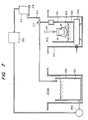
- Fig. 1 is a system diagram schematically illustrating the construction of a typical vapor drying apparatus embodying the present invention.
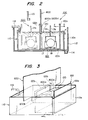
- Fig. 2 is a cross section of the part of the vapor drying apparatus for entry of a wafer-supporting carrier into the interior of the vapor drying apparatus.
- Fig. 3 is a perspective view of the essential part of Fig. 2.
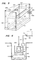
- Fig. 4 is a cross section illustrating another typical vapor drying apparatus embodying the present invention. It represents a case of adopting a pass-through room as the part for entry of the wafer and as the room for discharge thereof.
- Fig. 5 is a perspective view of the essential part of the pass-through room of Fig. 4.
- Fig. 6 is a cross section illustrating a typical IPA vapor cleaning device suitable for the present invention.
- Fig. 7 is a cross section illustrating another typical IPA vapor cleaning device suitable for the present invention.
- Fig. 8 is a perspective view illustrating a typical IPA heating device suitable for the present invention.
- Fig. 9 is a cross section of a vapor cleaning device using the IPA heating means of Fig. 8.
- Fig. 10 is a cross section illustrating yet another IPA vapor cleaning device suitable for the present invention.
- Fig. 11 is a plan view of a lid for the IPA container illustrated in Fig. 10.
- Fig. 12 is a schematic cross section of the vapor drying apparatus of this invention additionally incorporating therein means for collection of IPA vapor.
- Fig. 13 is a cross section taken through Fig. 12 along the line A-A.
- Fig. 1 is a system diagram schematically illustrating the construction of a typical vapor drying apparatus embodying the present invention. The detailed constructions of the components of the vapor drying apparatus will be described afterward. Here, the construction of the invention and the operation of vapor drying will be outlined.
- a wafer charging part 100, a water washing part 200, and a vapor drying part 300 are disposed in the order mentioned. They are isolated from the ambience by a partition member 800.
- the aforementioned wafer charging part 100 and water washing part 200 are formed in one common DI water container 110, in which a suitable amount of DI water 120 is stored.
- One end (righthand end in the diagram) of the aforementioned partition member 800 is substantially vertically dipped down into the DI water to divide the DI water container into the wafer charging part 100 and the water washing part 200.
- the vapor drying part 300 incorporates a cleaning tank 310. On the bottom of the cleaning tank 310 is disposed heating means 340. On the heating means 340 is mounted a quartz container 315 holding therein IPA 320. When the IPA 320 is heated by the heating means 340, the vapor of the IPA 320 fills up the upper space of the quartz container 315. Above the IPA container 315 is disposed a water tank 312 storing therein the water to be used for cooling the IPA 320 or/and the heating means 340 in emergency such as overheating of IPA.
- a pass-through room 400 for discharge of a dried wafer is disposed as laid through the partition member 800.
- the pass-through room 400 is intended to remove the wafer out of the vapor drying apparatus without establishing direct communication between the interior and the exterior of the vapor drying apparatus. It is provided with an outer door 420 and an inner door 440.
- an IPA gas collector 600 adapted to collect the IPA gas floating in the space inside the partition member 800.
- An infrared heater 500 is disposed at a suitable position along the path for wafer transfer between the vapor drying part 300 and the pass-through room 400.
- Wafers 19 are mounted on or stowed in a carrier 17 at the wafer charging part 100 as illustrated in Fig. 1 and dipped in the DI water 120 held in the DI water container 110 as indicated by the arrow A and transferred through an opening remaining between the partition member 800 and the bottom of the DI water container 110 into the interior of the partition member 800 as indicated by the arrow B.
- the wafers supported on the carrier are lifted from the DI water 120 by a movable hanger 23 as indicated by the arrow C. Subsequently, the wafers 19 are transferred into the washing tank 310, there to be cleaned with IPA vapor. Thereafter, the wafers 19 set on the carrier 17 are transferred through the inner door 440 into the aforementioned pass-through room 400, taken out of the partition member 800 through the outer door 420, and forwarded to the subsequent step of treatment.
- Fig. 2 is a partial cross section illustrating the construction of a typical combination of the wafer charging part 100 and the water washing part 200 embodying the present invention.
- Fig. 3 is a perspective view of the essential part of the present embodiment of Fig. 2 minus an overflow tank 112.
- the container 110 is filled with the DI water 120.
- This DI water 120 is kept circulated by suitable known means.
- the DI water which overflows the upper edge of a righthand panel 110a of the container 110 as indicated by the arrow F enters an overflow tank 112 and is temporarily discharged via a discharge pipe 114. Then, the DI water is cleaned by filtration and returned via a water feed pipe 116 to the container 110.
- Fig. 1 omits illustrating the overflow tank 112 shown in Fig. 2.
- the partition panel 800 has lower extended parts 800a and 800b thereof (Fig. 3) immersed in the DI water 120.
- the lower central part of the partition panel 800 intervening between the lower extended parts 800a and 800b constitutes an indentation 800c intended to permit passage therethrough of an arm part 17a of the carrier 17.
- a transfer base 122 having a cross section of the shape of three sides of a rectangle is disposed as illustrated in Fig. 2 and Fig. 3.
- the transfer base 122 consisting of an outer panel 122a, an inner panel 122b, and a bottom panel 122c interconnecting the former two panels is so disposed under the DI water 120 that the bottom panel 122c will remain in contact with the bottom surface of the container 110.
- the aforementioned partition panel 800 is interposed between the outer panel 122a and the inner panel 122b.
- the dimensions of the transfer base 122 are selected so that the carrier 17 supporting thereon the wafers 19 may be set on the bottom panel 122c as illustrated in Fig. 2. Further, the relative dimensions of the container 110 and the transfer base 122 are selected so that the inner surface of the inner panel 122b will collide against the inner surface of the partition panel 800 when the aforementioned transfer base 122 is moved farthest to the right (indicated by the arrow D), and the inner surface of the outer panel 122a will collide against the outer surface of the partition panel 800 when the transfer base 122 is moved farthest to the left (indicated by the arrow E).
- the transfer base 122 when the transfer base 122 is moved farthest in the direction of the arrow D or the arrow E to bring the inner panel 122b or the outer panel 122a into collision against the partition panel 800, the indentation 800c in the partition panel 800 is completely closed by the aforementioned inner panel 122b or outer panel 122a. As the result, the atmosphere inside the vapor drying apparatus is completely isolated from the ambience in the condition described above.
- the operator takes hold of the upper part of the outer panel 122a of the transfer base 122 in his hands and draws out the transfer base 122 farthest in the direction of the arrow D.
- the transfer base 122 is set in place in the condition shown in Fig. 2 and Fig. 3.
- the atmosphere inside the vapor drying apparatus and the ambience are isolated from each other as described above.
- the operator lowers the carrier 17 supporting thereon the wafers 19 into the DI water 120 and sets it on the bottom panel 122c of the transfer base 122.
- the condition of the carrier 17 supporting thereon the wafers 19 and set in place on the transfer base 122 is indicated by the solid line in Fig. 2. While the carrier 17 is in this state, the upper part of the arm part 17a of the aforementioned carrier 17 protrudes from the surface of the DI water 120.
- the transfer base 122 is moved by the operator in the direction of the arrow E until the outer panel 122a collides against the partition panel 800.
- the condition in which the transfer base 122 assumes after this movement is indicated by a chain line in Fig. 2. Even at this time, similarly to the time the aforementioned condition was assumed, the atmosphere inside the vapor drying apparatus and the ambience are completely isolated from each other.
- the upper part of the arm part 17a of the carrier 17 finds its way through the indentation 800c in the partition panel 800.
- the carrier 17 supporting thereon the wafers 19 is inserted into the interior of the vapor drying device while it is kept resting on the transfer base 122 and immersed in the water.
- the carrier 17 supporting thereon the wafers 19 is left standing as immersed in the DI water 120.
- the wafers 19 have its surface washed with the DI water 120 which is kept circulated.
- the carrier 17 supporting thereon the wafers 19 is lifted by the movable hanger 23 which is fastened to a hole 17b of the arm part 17a. It is then forwarded to the subsequent step, i.e. into the vapor drying part 300 (Fig. 1).
- the atmosphere inside the vapor drying apparatus is allowed to communicate with the ambience through the indentation 800c in the partition panel 800 while the aforementioned transfer base 122 is moved in the direction of the arrow E to convey the carrier 17 supporting therein the wafers 19 into the interior of the aforementioned apparatus.
- nitrogen gas is constantly injected into the vapor drying apparatus for the purpose of keeping the interior of the partition panel 800 in a cleaner state.
- N2 gas nitrogen gas
- the interior of the vapor drying apparatus remains in the state of positive pressure relative to the atmospheric pressure outside the apparatus.
- the atmosphere inside the aforementioned apparatus is allowed to communicate with the ambient air during the insertion into the vapor drying apparatus of the carrier 17, the possibility of foreign particles forcing their way into the interior of the apparatus is practically absent.
- the carrier 17 supporting thereon the wafers 19 has been described as transported into the vapor drying apparatus by means of the transfer base 122 which has a cross section of the shape of three sides of a rectangle.
- This invention does not discriminate this transfer base by this particular cross section of the shape of three sides of a rectangle.
- the transfer base 122 may be formed in a cross section of the shape of letter L by omitting the inner panel 122b from the construction described above.
- the single lateral panel is desired to close the indentation 800c in the partition panel 800 and to isolate the atmosphere inside the vapor drying apparatus from the ambient air except when the carrier 17 supporting thereon the wafers 19 is inserted into the interior of the apparatus.
- the transfer base of the L-shaped cross section is desired to be pulled out and consequently the aforementioned carrier 17 to be set in a prescribed position, so that the subsequent operation of the insertion of the transfer base into the vapor drying apparatus may be completed as quickly as possible.
- the fluidal resistance offered by the DI water to the transfer base during its movement can be decreased by forming at least one perforation, for example, in the lateral panels of the aforementioned transfer base immersed in the DI water 120.
- the movement of the transfer base has been described as carried out by the hands of the operator. Alternatively, it may be automated by a suitable known method.
- the isolation of the atmosphere inside the vapor drying apparatus from the ambient air has been described as obtained by causing the lateral panel of the transfer base to close the identation 800c in the partition panel 800 except when the carrier 17 supporting thereon the wafers 19 passes the portion of the partition panel.
- this particular construction is not an exclusive requirement.
- the isolation mentioned above may be attained by a construction in which a movable shutter panel (not shown) adapted to close the indentation 800c is disposed on at least either of the right and left side surfaces of the partition panel 800 and is raised only during the passage of the carrier 17 through the partition panel 800 and is lowered to close the indentation 800c at all the other times.
- This vertical movement of the shutter panel may be effected manually or automatically.
- the aforementioned shutter panel may be slid up by means of an approach sensor or limit switch when the transfer base 122 is moved in the direction of the arrow E (Fig. 2).
- the incorporation of the indentation 800c in the partition panel 800 is not an indispensable requirement.
- one portion of the lower end of the partition panel may be adapted so as to be vertically movable.
- the aforementioned portion of the lower end of the partition panel 800 may be upwardly moved only during the passage of the carrier 17 and may be kept immersed in the DI water 120 at all the other times.
- This vertical movement of the partition panel may be effected manually or automatically. With an automatic mechanism, the movement may be attained by means of an approach sensor or limit switch in much the same way as in the case of the aforementioned shutter panel.
- the embodiment of Fig. 2 and Fig. 3 enables the insertion of the wafer-supporting carrier into the vapor drying apparatus to be carried out without necessitating insertion of human hands into the apparatus. Thus, it can preclude the entry of foreign particles into the apparatus, a fact which has constituted a hindrance to the aforementioned insertion of the carrier.
- the vapor drying part 300 incorporates therein the washing tank 310 made of stainless steel.
- the heating means 340 which is formed of an aluminum block having a heater contained therein in a tightly closed state is disposed.
- the IPA container 315 made of quartz and containing the IPA 320 is mounted thereon.
- a cooling coil (shown in Fig. 12) adapted to cool and condense the vapor of IPA 320 is disposed, though not shown in Fig. 4 for the sake of simplicity of illustration.
- the IPA of a suitable amount in the quartz container is warmed by the heat emanating from the heating means 340 and kept in a vaporized state within the container.
- the wafers 19 are brought into the IPA vapor, the wafers wet with the DI water cool and liquefy the IPA vapor and the liquefied IPA trickles down the wafer surface.
- the moisture adhering to the wafers is displaced with IPA and, consequently, the wafers are deprived of the moisture.
- the liquefaction of IPA ceases to occur when the wafers are gradually heated by the IPA vapor and the temperature of wafers are eventually equalized with that of the IPA vapor. In this manner, the particles adhering to the wafers in process of the cleaning with the DI water are washed off completely. Consequently, the wafer surface is brought to a dry state.
- Fig. 4 is a cross section illustrating another typical vapor drying apparatus embodying the present invention.
- the diagram particularly shows the concrete construction of the pass-through room.
- another pass-through room is used in the wafer charging part besides the pass-through room used in the wafer discharge part.
- the water washing part unlike that of the embodiment of Fig. 1, uses an independent DI water tank 110A and an overflow tank 112A.
- the vapor drying part 300 used in the present embodiment is identical with that used in the embodiment illustrated in Fig. 1.
- a rail base 411 adapted to hold thereon the wafer-supporting carrier is disposed in the inner lower portion.
- the outer door 420 adapted to be opened and closed manually (Fig. 5 and Fig. 1) is formed.
- a ceiling part 413 which is adapted to partition the wafer discharge part or the pass-through room 400 off the atmosphere inside the vapor drying apparatus.
- the ceiling part 413 is provided therein with the inner door 440 adapted to be automatically opened and closed by known means.
- the pass-through room 400 which serves as the wafer discharge part is isolated from the atmosphere inside the vapor drying apparatus by closing the inner door 440.
- first gas feed ducts 415a and 415b and second gas feed ducts 433a and 433b for feeding N2 gas (nitrogen gas) and an oxygen-containing gas (such as, for example, air) respectively to the interior of the wafer discharge part 400 are disposed as laid through the partition member 800 and an inner partition wall 432.
- gas discharge ducts 416a and 416b which are used for discharging the N2 gas fed through the first gas feed ducts 415a and 415b and the air fed through the aforementioned second gas feed ducts 416a and 416b.
- a suction duct 417 adapted to absorb and discharge particles possibly produced by the friction generated between the carrier and the rail base 411 when the carrier supporting thereon the wafers is drawn out.
- a plurality of perforations 418 formed in the central portion of the rail base 411 as illustrated in Fig. 5 are intended to lead the particles produced by the friction between the carrier and the rail base 411 to the suction duct.
- the construction of the wafer charging part or the insertion part 100A is substantially identical with that of the aforementioned wafer discharge part 400, except that the wafer charging part is not provided with the aforementioned second gas feed ducts 433a and 433b.
- the components of the wafer insertion part 100A which possess functions identical or equal to the functions of the components of the wafer discharge part or the pass-through room 400 are denoted by numerical symbols which are sums of 100 and the respective numerical symbols (400+) used in the wafer discharge part 400.
- the operator first opens the outer door of the wafer insertion part 100A and sets on the rail base 111 the carrier 17 supporting thereon the wafers 19. Then, the operator moves the aforementioned carrier along the rail base 111 to a prescribed position in the wafer insertion part 100A.
- the carrier 17 supporting thereon the wafers 19 and brought to the prescribed position on the rail base 111 is illustrated by a dotted line in Fig. 4.
- the operator closes the outer door (not shown) of the wafer insertion part 100A.
- the atmosphere inside wafer insertion part 100A is allowed to communicate with the ambient air, since the outer door is opened. In the condition assumed then, no direct communication is established between the atmosphere inside the vapor drying apparatus and the ambient air because the inner door 140 is kept closed.
- clean filtered N2 gas is constantly fed into the wafer insertion part 100A via the gas feed ducts 115a and 115b.
- the interior of the wafer insertion part 100A is kept in the state of positive pressure relative to the atmospheric pressure. Even when the outer door is opened for the insertion of the carrier 17 , there is virtually no possibility of foreign particles in the ambient air entering the interior of the wafer insertion part 100A.
- the N2 gas is sucked out of via the suction duct 117 and the perforations 118.
- the particles which are produced by the friction between the carrier 17 and the rail base 111 are discharged as entrained by the aforementioned N2 gas.
- the carrier 17 supporting thereon the wafers 19 When the carrier 17 supporting thereon the wafers 19 is placed in the wafer insertion part 100A, the carrier 17 is left standing in the wafer insertion part 100A for a prescribed duration after the closure of the outer door. This standing is necessary because the foreign particles possibly find their way into the aforementioned wafer insertion part 100A as described above during the manual insertion of the carrier 17 into the wafer insertion part 100A and they are to be discharged by the flow of the aforementioned N2 gas.
- the N2 gas fed via the gas feed ducts 115a and 115b is passed through the interior of the wafer insertion part 100A and exhausted and discharged by the aforementioned suction duct 117 and, at the same time, discharged additionally through the gas discharge ducts 116a and 116b. At this time, the aforementioned foreign particles are simultaneously discharged, with the result that the atmosphere inside the wafer insertion part 100A is brought to a clean condition.
- the inner door 140 is automatically opened by known means. Then, the movable hanger 23 descends into the wafer insertion part 100A and comes into engagement with the hole 17b in the carrier 17. By the movable hanger 23, the aforementioned carrier 17 is transported into the space inside the vapor drying apparatus. Thereafter, the inner door 140 is automatically closed.
- the wafer 19 brought out into the space inside the aforementioned vapor drying apparatus is immersed for cleaning in the DI water 120 in conjunction with the carrier 17 by the movable hanger 23. Subsequently, the wafers 19 and the carrier 17 are transported by the movable hanger 23 into the vapor drying part 300.
- the wafers 19 which have undergone the vapor drying treatment are lifted in conjunction with the carrier 17 by the movable hanger 23 to a position above the vapor drying tank 300 temporarily as indicated by the chain line in Fig. 4. Then, it is transported as indicated by the arrow H to a position above the wafer discharge part or the pass-through room 400. At this time, the inner door 440 of the wafer discharge part 400 is automatically opened by suitable means.
- the wafer 19 brought to the position above the aforementioned wafer discharge part 400 is inserted in conjunction with the carrier 17 into the wafer discharge part 400 by the movable hanger 23 as indicated by the arrow G and then set in place on the rail base 411.
- the state consequently assumed by the wafers 19 is illustrated by the solid line in Fig. 4.
- the movable hanger 23 slips off the hole 17b, ascends through the inner door 440, and departs from the wafer discharge part 400. Substantially at the same time, the inner door 440 is closed.
- the carrier 17 supporting thereon the wafers 19 When the carrier 17 supporting thereon the wafers 19 is placed on the rail base 411, it is left standing therein for a prescribed duration. This standing is necessary because the IPA adhering in the form of film or in a molecular thickness on the surfaces of the wafers 19 fresh from the vapor drying treatment must be completely removed by the flow of the N2 gas.
- the N2 gas fed through the gas feed ducts 415a and 415b may be heated in advance by a heater, for example.
- a heater for example.
- the duration prescribed for the standing of the carrier 17 on the rail base 411 can be shortened.
- the wafers, besides being dried with the N2 gas or the preheated N2 gas, are heated by irradiation of the infrared ray issued from at least one infrared lamp disposed at a prescribed position inside and/or outside the wafer discharge part 400, the duration of the standing of the carrier 17 on the rail base 411 required for thorough drying of the wafers 19 can be shortened further.
- Fig. 4 illustrates four infrared lamps 431a - 431d disposed inside the wafer discharge part 400.
- the wall portion of the partition panel 800 to be exposed to the infrared ray is naturally required to be made of a material previous to the infrared ray.
- the duration required for drying the wafer 19 has been described as shortened further by utilizing the irradiation of the infrared ray in combination with the N2 gas or the preheated N2 gas.
- early drying of the wafer 19 may be obtained by solely utilizing the irradiation of the infrared ray.
- the drying effected exclusively by the irradiation of the infrared ray is completed, it becomes necessary to feed the N2 gas into the wafer discharge part 400.
- the operator opens the outer door 420, takes hold of the carrier 17, pulls the carrier 17 along the rail base 411 toward himself, and removes the wafer 19 as supported on the carrier 17. Thereafter, the outer door 420 is closed.
- the interior of the wafer discharge part 400 similarly to that of the wafer insertion part 100A, is kept in the state of positive pressure relative to the atmospheric pressure by the supply of the N2 gas.
- the possibility that foreign particles in the ambient air will find their way into the wafer discharge part 400 when the outer door 420 is opened is substantially absent. Since the suction duct 417 continued to exhaust N2 gas through the perforations 418, the particles produced by the friction generated during the removal of of the carrier 17 can be discharged as entrained by the N2 gas.
- the atmosphere inside the wafer discharge part 400 will shortly assume a thoroughly clean state.
- the subsequent carrier 17 supporting thereon new wafers 19 is brought in by the movable hanger 23 in the next round of operation and the inner door is consequently opened, therefore, the atmosphere inside the vapor drying apparatus will not be polluted.
- the aforementioned irradiation with the infrared ray for expediting the drying is not required to be carried out exclusively within the pass-through room 400.
- the wafers 19 which have undergone the vapor drying treatment in the vapor drying part are lifted in conjunction with the carrier 17 temporarily to the position above the vapor drying part 300.
- the conditions assumed in consequence of this operation is indicated by the chain line in Fig. 4.
- Fig. 4 illustrates three infrared lamps 13a - 13c arranged inside the vapor drying apparatus in such a manner that the infrared ray will impinge upon the wafers 19 while the carrier 17 supporting thereon the wafers 19 is being moved horizontally in the direction of the arrow H.
- the infrared lamps for the projection of the infrared ray may be disposed outside the vapor drying apparatus.
- the partition panel 800 which is exposed to the infrared ray should be made of a material transparent to the infrared ray.
- the supply of N2 gas is discontinued after or during the aforementioned treatment for rapid drying. Then, the supply of a cleaned oxygen-containing gas (hereinafter represented by "air") through the second gas feed ducts 433a and 433b is started. Simultaneously with this supply of air, the irradiation on the wafers 19 with far ultraviolet light is started. To be specific, the wafers 19 are irradiated with the far ultraviolet light issued from at least one low-voltage mercury vapor lamp (not shown) disposed at a prescribed position inside and/or outside the wafer discharge part 400.
- air a cleaned oxygen-containing gas
- the atmosphere (air) inside the wafer discharge part 400 is ozonized by the well-known mechanism.
- the ozone and the far ultraviolet light By the combined action of the ozone and the far ultraviolet light, such organic substances as carbon adhering to the surface of the wafers 19 are decomposed and diffused into the ambient air. As the result, the organic substances are completely removed from the surface of the wafers 19.
- the operator opens the outer door 420 and takes out the carrier 17 supporting thereon the wafers 19 in the same manner as already described. After the removal of the carrier 17, the operator closes the aforementioned outer door 420.
- the outer door 420 is closed, the aforementioned supply of air to the interior of the wafer 400 is stopped and the supply of N2 gas thereto is resumed. As a result, the air in the inside space of the wafer discharge part 400 is displaced with N2 gas and the space is kept in a clean state.
- the vapor drying apparatus has been described as possessed of the wafer insertion part 100A and the wafer discharge part 400 each using the pass-through room construction of this invention and as separately disposed of each other. It is not always necessary to have the wafer insertion part 100A and the wafer discharge part 400 disposed separately of each other. In the embodiment illustrated in Fig. 4, for example, the wafer insertion part 100A may be omitted and the wafer discharge part 400 adapted to fulfil concurrently the function of a wafer insertion part.
- the carrier 17 supporting thereon the wafers 19 is placed on the rail base 411 in the wafer discharge part 400 and, thereafter, the carrier 17 is transferred into the vapor drying apparatus.
- the cleaning treatment in the water washing part 200A and the vapor drying treatment in the vapor drying part 300 are carried out sequentially .
- the carrier 17 supporting thereon the wafers 19 is returned again to the wafer discharge part 400 and the carrier 17 is taken out as described above.
- the wafer charging part 100A and the water washing part 200A in the embodiment of Fig. 4 are interchangeable with the wafer charging part 100 and the water washing part 200 in the embodiment of Fig. 1.
- the cleaning liquid such as IPA 320
- the cleaning liquid put in a suitable amount in the quartz container 315 is warmed with the heat generated by the heater built in an aluminum block, specifically the heating means 340, and, therefore, is kept in a vaporized state inside the quartz container 315.
- the IPA is a liquid which has an ignition point of 310°C, a boiling point of 82.7°C, and a flash point of 21°C.
- the heater used for heating the IPA 320 is kept in a completely closed state in the aluminum block 340. This arrangement is intended to preclude the possibility of the IPA and the vapor thereof catching fire when the heater is exposed.
- a cooling coil (not shown in Fig. 6 but shown in Fig. 12) is disposed in such a manner as to preserve a space for free passage of the wafer-supporting carrier. By the cooling water flowing through the cooling pipe, the vaporized IPA is cooled and liquefied and returned for re-use to the quartz container 315.
- the concentration of the vapor of IPA 320 outside the quartz container, i.e. in the space inside the vapor drying apparatus is not suffered to rise above a prescribed level under the normal condition.
- the concentration of the vapor of IPA 320 is much lower than the lower explosive limit (hereinafter referred to as "LEL" for short). It is kept lower than 50 to 20% of the LEL. It may be safely concluded, therefore, that in the normal condition, there is no possibility of the vapor drying part catching fire or causing explosion.
- LEL lower explosive limit
- the senor does not function normally to induce the diffusion of carbon dioxide gas when the sensor itself is out of order or when the power supply is damaged as by the fall of a thunderbolt. Further in the case of the power failure, the circulation of the cooling water through the cooling pipe is also stopped.
- Fig. 6 is specially devised so that when the sensor goes out of order or when the power supply is stopped as by the fall of a thunderbolt, water is poured onto such heating means 340 as aluminum block having a heater water-tightly built therein and/or into the container 315 holding the IPA to cause an abrupt fall of the temperature of the IPA 320 and impede the vaporization of IPA.
- a tank 312 storing water therein is installed on a support base 318 in the embodiment of Fig. 6.
- This tank 312 is provided with a water discharge pipe 319 incorporating a cock 311.
- the operator opens the cock 311 to release the water from the tank 312 and shower on the aluminum box 340 and cause sudden cooling of the aluminum box 340 and, at the same time, shower in the interior of the quartz container 315 and dilute the IPA 320 and impede the vaporization of IPA.
- the temperature of the IPA 320 For the purpose of preventing the IPA 320 from vaporization, it suffices to keep the temperature of the IPA 320 below its boiling point 82.7°C.
- the device of showering both on the aluminum box 340 and in the quartz container 315 as contemplated in the present embodiment is not always necessary.
- the desire to keep the temperature of IPA 320 below the aforementioned level and curb the vaporization of IPA can be fulfilled by showering either of the two components mentioned above.
- the simultaneous showering of the two components proves desirable only in the sense that the temperature of IPA 320 can be amply lowered rapidly.
- a container 252 has the DI water 120 stored therein.
- a pump 254 lifts the DI water 120 at a fixed rate and returns it through a filter 255 to the tank 312.
- a three-way cock 317 is intended to permit selection between forwarding the DI water from the tank 312 to the vapor drying part 300 and forwarding it to the container 252 side. This switching is manually effected in the present embodiment.
- the three-way cock 317 is set so that the DI water stored in the tank 312 will flow through the water discharge tube 319 into the container 252.
- the pump 254 is adapted to return the DI water through the filter 255 to the tank 312 in substantially the same flow volume as the water flowing into the container 252.
- the container 252 constantly remains filled with a substantially fixed amount of the DI water 120 being circulated for the cleaning of the wafers 19.
- the wafers 19 which have undergone preliminary cleaning with the DI water so circulated are transferred, as described above, by the movable hanger 23 into the vapor of IPA 320 for drying.
- the supply of the DI water so far conducted to the container 252 can be switched to the interior of the vapor drying part 300 by manually turning the three-way cock 317.
- the DI water is diverted as the cooling water to be released during power failure, when the power failure ceases and the normal operation of the apparatus resumes, it suffices only to carry out the step of vapor drying instead of starting the steps of DI water washing and vapor drying all over again from the beginning.
- the operator is invariably required to take notice of abnormality of the sensor or of the status of power failure, manipulate the cocks 311 and 317, and release plain water or the DI water into the vapor drying part 300. It is naturally permissible to produce these actions automatically by effecting the recognition of the abnormality of the sensor or the status of power failure with suitable means of detection and opening the cocks accordingly or switching the cocks for extending passage to the vapor drying part 300.
- Fig. 8 and Fig. 9 respectively illustrate heating means 340A devised specially to solve the aforementioned problem and the vapor drying part 300 using this heating means.
- a main body 331 of the heating means 340A namely a heater block for heating the IPA 320
- This main body 331 is provided with a plurality (three in the embodiment of Fig. 8) of holes 332 each in the form of a sheath.
- sheathed heaters are inserted one each in these sheathlike holes 332.
- These sheathed heaters are incorporated in a tightly closed state inside the sheathlike holes 332 by suitable known means lest their heat-generating parts should be exposed to the ambient air.
- a water cooling tube 333 is zigzagged substantially parallel to the sheathlike holes 332 in such a manner as to run halfway in the spaces intervening between the sheathlike holes 332.
- This water cooling tube 333 is extended in two ways from the heater block 340A.
- the leading end of one of the extended tubes, 333a is connected to the cooling water storage tank 312 which is placed on the support base 318.
- the extended tube is provided near the leading end thereof with a cock 311.
- the other ended tube 333b of the water cooling tube 333 is connected to a water discharge outlet (not shown).
- the cock 311 designed for manual operation in the present embodiment permits extension of the flow of the cooling water to the interior of the heater block 340A.
- the heater block 340A When the flow of electric current to the sheathed heaters is started, the heater block 340A is heated and the IPA 320 is consequently vaporized.
- the wafers 19 cleaned with the aforementioned DI water and supported on the carrier 17 are brought into the vapor of IPA 320 by the movable hanger 23, the wafers 19 are cleaned and dried as described above.
- the operator manually opens the cock 311 to start release of the cooling water from the tank 312 into the cooling tube 333 and effect sudden cooling of the heater block 340A.
- the cooling water which flows out of the tank 312 passes the extended tube 333a enters the heater block 340A, absorbs excess heat in the heater block 340A, flows through the other extended tube 333b and departs from the discharge outlet (not shown). As the result, the heater block 340A is rapidly cooled.
- Fig. 9 can be utilizes as protective means when the sensor used in detecting the fact that the vapor of IPA is abnormally diffused outside the quartz container 315 and the concentration of the vapor increases beyond a prescribed level goes out of order.
- the abnormal condition mentioned above is recognized visually or by some other suitable means, the operator has only to open the cock 311 manually in the same manner as in the case of power failure described above.
- heater block 340A can be utilized effectively for the vapor drying apparatus of Fig. 7 in which the DI water primarily used for cleaning is diverted as cooling water in case of emergency.
- the quartz container used invariably in all the embodiments of this invention described above is produced by fusing five transparent quartz plates in the form of five faces of a cube. As the result, diffusion of heat occurs more at the corners of the container than at any other portion of the container. The IPA temperature distribution and, consequently, the vapor concentration distribution within the container, therefore, become uneven. Thus, there are times when the vapor drying of the wafers cannot be obtained thoroughly at the corners of the container. In other words, the conventional rectangular container has the disadvantage that the vapor drying of the wafers is not conducted uniformly.
- the temperature of the heating must be elevated to a level proper at the corners.
- the elevation of the heating temperature implies that the concentration of the IPA vapor tends to exceed the allowable limit and the danger of fire or explosion grows when the IPA vapor is not condensed and returned to the quartz container but is diffused in the space inside the apparatus owing to power failure, for example.
- the rectangular container is obtained by fusing five transparent quartz plates as described above, it is deficient in mechanical strength so that particularly the corners thereof have the possibility of readily sustaining damage when they collide against other components or devices.
- the container is increased in wall thickness for the purpose of gaining in mechanical strength, it becomes susceptible to fracture by thermal stress.
- the rectangular container is produced by fusing quartz plates as described above, the production thereof consumes so much time as to render mass production and uniformization of quality difficult. Moreover, the produced container itself is expensive.
- the quartz container to be used for the vapor drying of the semiconductor wafer is made of high-purity translucent quartz in the form of a blind tube.
- Fig. 10 is a partial cross section schematically illustrating the construction of a vapor drying part 300 beneficial for the present invention.
- a depressed part 340c of a spheroidal quadric (such as sphere or paraboloid).
- This aluminum box has a heater (not shown) embedded therein in a tightly closed state as laid along the aforementioned depressed part.
- a quartz container 315c in the form of a blind tube holding IPA 320 therein.
- This quartz container 315c is formed of a high-purity translucent quartz.
- the bottom of this quartz container has a spheroidal quadric intimately matched to the depressed part 340c.
- the upper edge of the quartz container 315c is in a tapered shape.
- a lid 350 shaped in the form of a concave mirror or inverted bowl and provided therein with a cooling water path has its edge in contact with the inner circumferential surface of the tapered edge 315e. As generally accepted, the lid enjoys tightness of closure when this lid and the main body which are brought into mutual contact both have circular faces.
- the lid 350 is provided at the center thereof with a perforation 350a so that the carrier 17 supporting thereon the wafers 19 may be placed in and out of the quartz container 315c.
- the cooling water path laid in the lid 350 is provided with a water feed inlet 350b connected to the water feed tube 11 and a water discharge outlet 350c connected to the water discharge tube 12. As the result, the cooling water fed out of the water feed tube 11 flows through the cooling water path inside the lid 350 as shown by the arrow M and flows out of the water discharge tube 12 as shown by the arrow N.
- the quartz container 315c is formed of high-purity translucent quartz in the form of a blind tube, this embodiment does not experience the ununiform vapor drying of the waferswhich is inevitably entrailed by the embodiment using a rectangular container. This is because the quartz container 315c in the form of a blind tube, unlike the conventional rectangular container, has no corner and, therefore, cannot entail the ununiform IPA temperature distribution or vapor concentration distribution due to thermal diffusion in corners.
- the temperature of the heater during the operation of the apparatus can be controlled to a level (closer to the boiling point 82.7 °C) lower than the conventional rectangular container because the thermal conduction from the aluminum box 340b to the IPA held inside the container 315c is uniformized. As the result, the rate at which the concentration of the IPA vapor increases such as during power failure can be mitigated.
- the safety of the vapor drying apparatus can be heightened as compared with the conventional countertype because the highest heater temperature is lower than the conventional rectangular container.
- the vaporized IPA is cooled and liquefied by the cooling water flowing inside the lid 350 and then returned into the quartz container 315c.
- the cooling pipe devised as described above with respect to the other embodiment may be disposed in the upper inner part of the container.
- the quartz container formed of high-purity translucent quartz in the form of a blind tube as illustrated in Fig. 10 and Fig. 11 can be integrally molded in the same way as a high-purity opaque crucible is produced for use in the production of a bar of single crystal semiconductor.
- the production of this quartz container permits a generous saving in time as compared with the production of the conventional rectangular container which inevitably entails fusion of quartz plates.
- the present container enjoys the advantage that it is integrally molded and, therefore, possesses high mechanical strength.
- the container made of this quartz minimally develops thermal stress even in the presence of temperature difference and, therefore, does not easily sustain fracture due to thermal stress.
- the vaporized IPA is virtually wholly condensed and returned into the quartz container owing to the cooling water flowing through the cooling pipe disposed in the upper inner part of the quartz container or through the perforation in the lid of the container. It is, however, difficult for the vaporized IPA to be thoroughly liquefied and returned into the quartz container. Thus, the portion of the IPA vapor which escapes being condensed and returned to the quartz container inevitably diffuses upwardly outside the quartz container and eventually floats in the space inside the vapor drying apparatus.
- the flotation of the IPA vapor in the space inside the vapor drying apparatus exposes the apparatus to the danger of fire or explosion and proves undesirable for the safety of the apparatus. It also entails the possibility that the organic substances entrained by IPA will adhere to the wafer which has already been cleaned.
- Fig. 12 is a partial cross section illustrating another embodiment of this invention, wherein means capable of cooling and liquefying the floating volatile cleaning liquid is disposed at a prescribed place inside the vapor drying apparatus.
- an element 814 (such as, for example, a Peltier element) capable of cooling and liquefying the vaporized IPA is disposed on the ceiling part 800a of the partition panel 800 of the vapor drying apparatus, i.e. at the position above the vapor drying part 300.
- a receptacle plate 815 for collecting the liquefied IPA is disposed directly below the aforementioned Peltier element.
- Fig. 13 is a partially sectioned side view taken through Fig. 12 along the line A-A for the purpose of illustrating clearly the manner in which the Peltier element 814 and the receptacle plate 815 are attached to the inner surface of the partition member 800.
- the IPA which is collected in the receptacle plate 815 is discharged out of the vapor drying apparatus through the discharge tube 16.
- the vaporized IPA floats in the space inside the vapor drying apparatus, particularly in the upper portion of the vapor drying part 300.
- the floating IPA When the floating IPA is brought into contact with the cool contact of the Peltier element 814 and consequently cooled, it is condensed into liquid drops.
- the liquid drops collect and grow to a certain size, the grown beads flow down the surface of the Peltier element 814 and fall off the lower leading end of the Peltier element into the receptacle plate 815.
- the liquid IPA so collected in the receptacle plate 815 is discharged out of the vapor drying apparatus via the liquid discharge tube 16.
Claims (16)
- Vorrichtung zum Dampftrocknen, die folgendes aufweist: einen Reinigungsabschnitt (200) mit einem ersten Behälter (110), in dem eine Reinigungsflüssigkeit (120) zur Reinigung eines vorgegebenen Gegenstandes (19) aufbewahrt wird, einen Dampftrocknungsabschnitt (300) mit einem zweiten Behälter (315), in dem eine flüchtige Reinigungsflüssigkeit (320) gespeichert wird, und einer Einrichtung (340) zum Erhitzen und Verdampfen der flüchtigen Reinigungsflüssigkeit, mit der der in dem Reinigungsabschnitt (200) gereinigte vorgegebene Gegenstand (19) dem Dampf der flüchtigen Reinigungsflüssigkeit ausgesetzt werden kann und dadurch das Dampftrocknen des vorgegebenen Gegenstandes durchgeführt werden kann,
ein Trennungsteil (800) zum luftdichten Trennen des Reinigungsabschnittes (200) und des Dampftrocknungsabschnittes (300) von der umgebenden Atmosphäre und zum Definieren eines Raums zum Dampftrocknen,
eine Einrichtung (100, 400) zum Einführen des vorgegebenen Gegenstandes durch das Trennungsteil in den Raum zum Dampftrocknen bzw. zum Herausnehmen des vorgegebenen Gegenstandes aus diesem Raum, und
eine Trägereinrichtung (17) zum Überführen des vorgegebenen Gegenstandes in gewünschte Positionen innerhalb des Raums zum Dampftrocknen,
wobei das untere vordere Ende (800a, 800b) des Trennungsteils (800) in die Reinigungsflüssigkeit (120) eingetaucht ist, um den ersten Behälter (110) in eine Innenseite (200) und eine Außenseite (100) aufzuteilen,
wobei die Vorrichtung mit einer Überführungsbasis (122) zum Halten der den vorgegebenen Gegenstand tragenden Trägereinrichtung (17) auf deren Bodenplattenteil (122c) ausgestattet ist, wodurch der Gegenstand mit dem Träger (17) von der Außenseite (100) zu der Innenseite (200) des ersten Behälters (110) in einer Lage, in der er bis unter die Oberfläche der Reinigungsflüssigkeit (120) eingetaucht ist, überführt werden kann, und
wobei die Trägereinrichtung (17) ein Armteil (17a) aufweist, das nach oben aus der Oberfläche der Reinigungsflüssigkeit (120) herausragt. - Vorrichtung zum Dampftrocknen nach Anspruch 1, die weiterhin eine in dem unteren vorderen Endteil des Trennungsteils (800) ausgebildete Öffnung (800c) aufweist, um das Armteil (17a) durch das Trennungsteil (800) hindurchzulassen, wenn die Überführungsbasis (122) von der Außenseite auf die Innenseite des Behälters (110) bewegt wird, und eine Einrichtung zum Schließen der Öffnung (800c), wenn die Überführungsbasis (122) an eine vorgeschriebene Position auf der Innenseite des Behälters (110) bewegt worden ist.
- Vorrichtung zum Dampftrocknen nach Anspruch 2, worin die Öffnung ein in dem unteren Teil des Trennungsteils (800) ausgebildeter Einschnitt (800c) und die Einrichtung zum Schließen der Öffnung ein Plattenteil (122a) ist, das einstückig mit der Überführungsbasis (122) ausgebildet ist und nach oben aus der Oberfläche der Reinigungsflüssigkeit herausragt, um den Einschnitt zu schließen.
- Vorrichtung zum Dampftrocknen, die folgendes aufweist: einen Reinigungsabschnitt (200) mit einem ersten Behälter (110), in dem eine Reinigungsflüssigkeit (120) zur Reinigung eines vorgegebenen Gegenstandes (19) aufbewahrt wird, einen Dampftrocknungsabschnitt (300) mit einem zweiten Behälter (315), in dem eine flüchtige Reinigungsflüssigkeit (320) gespeichert wird, und einer Einrichtung (340) zum Erhitzen und Verdampfen der flüchtigen Reinigungsflüssigkeit (320), mit der der in dem Reinigungsabschnitt (200) gereinigte vorgegebene Gegenstand (19) dem Dampf der flüchtigen Reinigungsflüssigkeit ausgesetzt werden kann und dadurch das Dampftrocknen des vorgegebenen Gegenstandes durchgeführt werden kann,
ein Trennungsteil (800) zum luftdichten Trennen des Reiniabschnittes (200) und des Dampftrocknungsabschnittes (300) von der umgebenden Atmosphäre und zum Definieren eines Raums zum Dampftrocknen,
eine Einrichtung (100, 400) zum Einführen des vorgegebenen Gegenstandes durch das Trennungsteil in den Raum zum Dampftrocknen bzw. zum Herausnehmen des vorgegebenen Gegenstandes aus diesem Raum, und
eine Trägereinrichtung (17) zum Überführen des vorgegebenen Gegenstandes in gewünschte Positionen innerhalb des Raums zum Dampftrocknen,
wobei die Vorrichtung zum Dampftrocknen mit einer Einrichtung (431) ausgestattet ist zum Erhitzen des gereinigten vorgegebenen Gegenstandes (19) und raschen Entfernen der an den Oberflächen des vorgegebenen Gegenstandes haftenden verdampften Reinigungsflüssigkeit zwischen dem Zeitpunkt, an dem der gereinigte Gegenstand der Dampftrocknungsbehandlung unterzogen wurde und dem Zeitpunkt, an dem der Gegenstand aus der Vorrichtung herausgenommen wird,
wobei die Einrichtung (100, 400) einen Gegenstand-Beladungsabschnitt (100) aufweist, der Reinigungsabschnitt ein Flüssigkeitswaschabschnitt (200) ist, der Gegenstand-Beladungsabschnitt und der Waschabschnitt in einem gemeinsamen Flüssigkeitsbehälter (110) ausgebildet sind, das Trennungsteil (800) den Flüssigkeitsbehälter in den Gegenstand-Beladungsabschnitt (100) und den Waschabschnitt (200) aufteilt und eine Überführungsbasis (122) in dem Flüssigkeitsbehälter (110) vorgesehen ist, um die Trägereinrichtung (17) von dem Beladungsabschnitt (100) durch das Trennungsteil (800) in den Waschabschnitt (200) zu verschieben. - Vorrichtung zum Dampftrocknen, die folgendes aufweist: einen Reinigungsabschnitt (200) mit einem ersten Behälter (110), in dem eine Reinigungsflüssigkeit (120) zur Reinigung eines vorgegebenen Gegenstandes (19) aufbewahrt wird, einen Dampftrocknungsabschnitt (300) mit einem zweiten Behälter (315), in dem eine flüchtige Reinigungsflüssigkeit (320) gespeichert wird, und einer Einrichtung (340) zum Erhitzen und Verdampfen der flüchtigen Reinigungsflüssigkeit (320), mit der der in dem Reinigungsabschnitt (200) gereinigte vorgegebene Gegenstand (19) dem Dampf der flüchtigen Reinigungsflüssigkeit ausgesetzt werden kann und dadurch das Dampftrocknen des vorgegebenen Gegenstandes durchgeführt werden kann,
ein Trennungsteil (800) zum luftdichten Trennen des Reinigungsabschnittes (200) und des Dampftrocknungsabschnittes (300) von der umgebenden Atmosphäre und zum Definieren eines Raums zum Dampftrocknen,
eine Einrichtung (100, 400) zum Einführen des vorgegebenen Gegenstandes durch das Trennungsteil in den Raum zum Dampftrocknen bzw. zum Herausnehmen des vorgegebenen Gegenstandes aus diesem Raum, und
eine Trägereinrichtung (17) zum Überführen des vorgegebenen Gegenstandes in gewünschte Positionen innerhalb des Raums zum Dampftrocknen, worin
die Einrichtung zum Einführen des vorgegebenen Gegenstandes in den Raum zum Dampftrocknen bzw. zum Herausnehmen des vorgegebenen Gegenstandes aus dem Raum durch das Trennungsteil ein Durchlaßraum (100A, 400) ist, der selektiv durch eine innere Tür (440) in Verbindung mit dem Raum zum Dampftrocknen und durch eine äußere Tür (420) mit der umgebenden Atmosphäre sein kann, und
der Durchlaßraum (100A, 400) mit einer innerhalb der inneren Tür (140, 440) angeordneten Trägerhalteeinrichtung (111, 411) ausgestattet ist, um die den vorgegebenen Gegenstand tragende Trägereinrichtung (17) zu halten, mindestens ein Gaszufuhrkanal (115, 415) vorgesehen ist zum Zuführen eines vorbestimmten Gases in den Durchlaßraum, ein Gasentladungskanal (116, 416) zum Entladen des Gases aus dem Durchlaßraum vorgesehen ist, und eine Einrichtung zum alternativen Öffnen oder Schließen der inneren Tür (140, 440) und der äußeren Tür (420) vorgesehen ist, um den Durchtritt der Trägereinrichtung (17) zu ermöglichen. - Vorrichtung zum Dampftrocknen nach Anspruch 5, worin das vorbestimmte Gas N₂-Gas ist.
- Vorrichtung zum Dampftrocknen nach Anspruch 5, worin die Trägerhalteeinrichtung (111, 411) Perforationen (118, 418) hat, durch die das Gas innerhalb des Durchlaßraums ausgelassen und abgeführt wird.
- Vorrichtung zum Dampftrocknen nach Anspruch 5, die zum Zuführen eines Sauerstoff enthaltenden Gases zusätzlich zu dem Gaszufuhrkanal (415) mit einem zweiten Gaszufuhrkanal (433) und einer Einrichtung zum Bestrahlen des Gegenstandes (19), der auf der auf der Halteeinrichtung (411) gehaltenen Trägereinrichtung (17) getragen wird, mit fernem ultraviolettem Licht ausgestattet ist.
- Vorrichtung zum Dampftrocknen, die folgendes aufweist: einen Reinigungsabschnitt (200) mit einem ersten Behälter (110), in dem eine Reinigungsflüssigkeit (120) zur Reinigung eines vorgegebenen Gegenstandes (19) aufbewahrt wird, einen Dampftrocknungsabschnitt (300) mit einem zweiten Behälter (315), in dem eine flüchtige Reinigungsflüssigkeit (320) gespeichert wird, und einer Einrichtung (340) zum Erhitzen und Verdampfen der flüchtigen Reinigungsflüssigkeit, mit der der in dem Reinigungsabschnitt (200) gereinigte vorgegebene Gegenstand dem Dampf der flüchtigen Reinigungsflüssigkeit ausgesetzt werden kann und dadurch das Dampftrocknen des vorgegebenen Gegenstandes durchgeführt werden kann,
ein Trennungsteil (800) zum luftdichten Trennen des Reinigungsabschnittes (200) und des Dampftrocknungsabschnittes (300) von der umgebenden Atmosphäre und zum Definieren eines Raums zum Dampftrocknen,
eine Einrichtung (100, 400) zum Einführen des vorgegebenen Gegenstandes durch das Trennungsteil in den Raum zum Dampftrocknen bzw. zum Herausnehmen des vorgegebenen Gegenstandes aus dem Raum, und
eine Trägereinrichtung (17) zum Überführen des vorgegebenen Gegenstandes in gewünschte Positionen innerhalb des Raums zum Dampftrocknen, worin
der zweite Behälter (315) auf der Einrichtung zum Erhitzen (340) getragen wird und einen Kühlwasserbehälter (312) hat, der in einer Position, in der er höher liegt als die Oberfläche der flüchtigen Reinigungsflüssigkeit (320), gehalten wird, wobei ein Wasserabflußrohr (319) zum Zuführen des Kühlwassers von dem Behälter zu dem zweiten Behälter und/oder der Einrichtung zum Erhitzen und zur Abgabe des Wassers von dort vorgesehen ist sowie ein Hahn (311, 317), der in der Mitte des Abflußrohres angeordnet ist und die Wasserabgabe steuern kann. - Vorrichtung zum Dampftrocknen nach Anspruch 9, worin das Wasser deionisiertes Wasser ist.
- Vorrichtung zum Dampftrocknen nach Anspruch 9, worin die Einrichtung zum Erhitzen (340) ein Heizblock (340A) mit einem darin dicht abgeschlossen eingebauten Heizgerät ist, wobei der Heizblock (340A) ein darin eingebettetes Wasserkühlrohr (333) hat und das Kühlwasserrohr mit dem Wasserabflußrohr (319) verbunden ist.
- Vorrichtung zum Dampftrocknen, die folgendes aufweist: einen Reinigungsabschnitt (200) mit einem ersten Behälter (110), in dem eine Reinigungsflüssigkeit (120) zur Reinigung eines vorgegebenen Gegenstandes (19) aufbewahrt wird, einen Dampftrocknungsabschnitt (300) mit einem zweiten Behälter (315), in dem eine flüchtige Reinigungsflüssigkeit (320) gespeichert wird, und einer Einrichtung (340) zum Erhitzen und Verdampfen der flüchtigen Reinigungsflüssigkeit, mit der der in dem Reinigungsabschnitt (200) gereinigte vorgegebene Gegenstand (19) dem Dampf der flüchtigen Reinigungsflüssigkeit ausgesetzt werden kann, um dadurch das Dampftrocknen des vorgegebenen Gegenstandes durchzuführen; wobei in der Vorrichtung zum Dampftrocknen
die Einrichtung zum Erhitzen (340) ein Blockteil (340b) ist mit einem auf dessen Oberseite ausgebildeten tiefergelegten Teil (340c) in Form einer sphäroidischen Quadrik und einem darin dicht abgeschlossen eingebauten Heizgerät, und wobei der zweite Behälter (315) aus Quarz in Form eines blinden Rohres ausgebildet ist und ein Unterteil hat, das in einer sphäroidischen Quadrik, die dicht abschließend auf den tiefergelegten Teil aufgebracht ist, ausgebildet ist. - Vorrichtung zum Dampftrocknen nach Anspruch 12, worin der Quarz durchscheinender Quarz hoher Reinheit ist.
- Vorrichtung zum Dampftrocknen nach Anspruch 12, worin eine Öffnung des zweiten Behälters (315) mit einem Deckel (350) abgedeckt ist und der Deckel in seinem Inneren eine Kühlwasserleitung und in seiner Mitte auch eine Perforation (350a) hat, um das Ein- und Austreten des vorgegebenen Gegenstandes zu ermöglichen.
- Vorrichtung zum Dampftrocknen, die folgendes aufweist: einen Reinigungsabschnitt (200) mit einem ersten Behälter (110), in dem eine Reinigungsflüssigkeit (120) zur Reinigung eines vorgegebenen Gegenstandes (19) aufbewahrt wird, einen Dampftrocknungsabschnitt (300) mit einem zweiten Behälter (315), in dem eine flüchtige Reinigungsflüssigkeit (320) gespeichert wird, und einer Einrichtung (340) zum Erhitzen und Verdampfen der flüchtigen Reinigungsflüssigkeit, mit der der in dem Reinigungsabschnitt (200) gereinigte vorgegebene Gegenstand (19) dem Dampf der flüchtigen Reinigungsflüssigkeit ausgesetzt werden kann, um dadurch das Dampftrocknen des vorgegebenen Gegenstandes durchzuführen, ein Trennungsteil (800) zum luftdichten Trennen des Reinigungsabschnittes (200) und des Dampftrocknungsabschnittes (300) von der umgebenden Atmosphäre und zum Definieren eines Raums zum Dampftrocknen,
eine Einrichtung (100, 400) zum Einführen des vorgegebenen Gegenstandes durch das Trennungsteil in den Raum zum Dampftrocknen bzw. zum Herausnehmen des vorgegebenen Gegenstandes aus diesem Raum, und
eine Trägereinrichtung (17) zum Überführen des vorgegebenen Gegenstandes in gewünschte Positionen innerhalb des Raums zum Dampftrocknen,
wobei die Vorrichtung zum Dampftrocknen weiterhin eine Kühl- und Verflüssigungseinrichtung (600) aufweist, so daß ein von dem zweiten Behälter (315) in den Raum zum Dampftrocknen eindiffundiertes Gas der flüchtigen Reinigungsflüssigkeit (320) in dem Raum zum Dampftrocknen gekühlt und verflüssigt werden kann. - Vorrichtung zum Dampftrocknen nach Anspruch 15, worin die Kühl- und Verflüssigungseinrichtung (600) ein Peltierelement (814) ist.
Priority Applications (1)
| Application Number | Priority Date | Filing Date | Title |
|---|---|---|---|
| AT86101834T ATE75784T1 (de) | 1985-04-15 | 1986-02-13 | Einrichtung zum dampftrocknen. |
Applications Claiming Priority (14)
| Application Number | Priority Date | Filing Date | Title |
|---|---|---|---|
| JP7839985A JPS61237430A (ja) | 1985-04-15 | 1985-04-15 | 半導体蒸気乾燥洗浄用石英容器 |
| JP7839785A JPS61237429A (ja) | 1985-04-15 | 1985-04-15 | 蒸気乾燥洗浄装置 |
| JP78397/85 | 1985-04-15 | ||
| JP78399/85 | 1985-04-15 | ||
| JP115475/85 | 1985-05-30 | ||
| JP115476/85 | 1985-05-30 | ||
| JP11547685A JPS61276225A (ja) | 1985-05-30 | 1985-05-30 | 蒸気乾燥洗浄装置 |
| JP11547585A JPS61276224A (ja) | 1985-05-30 | 1985-05-30 | 物品洗浄装置 |
| JP156015/85 | 1985-07-17 | ||
| JP15601485A JPS6218037A (ja) | 1985-07-17 | 1985-07-17 | パススル−ル−ム |
| JP15601285A JPS6218036A (ja) | 1985-07-17 | 1985-07-17 | 蒸気乾燥洗浄装置 |
| JP156014/85 | 1985-07-17 | ||
| JP156012/85 | 1985-07-17 | ||
| JP15601585A JPS6218038A (ja) | 1985-07-17 | 1985-07-17 | 蒸気乾燥洗浄装置 |
Publications (3)
| Publication Number | Publication Date |
|---|---|
| EP0198169A2 EP0198169A2 (de) | 1986-10-22 |
| EP0198169A3 EP0198169A3 (en) | 1988-09-21 |
| EP0198169B1 true EP0198169B1 (de) | 1992-05-06 |
Family
ID=27565287
Family Applications (1)
| Application Number | Title | Priority Date | Filing Date |
|---|---|---|---|
| EP86101834A Expired - Lifetime EP0198169B1 (de) | 1985-04-15 | 1986-02-13 | Einrichtung zum Dampftrocknen |
Country Status (3)
| Country | Link |
|---|---|
| US (2) | US4736758A (de) |
| EP (1) | EP0198169B1 (de) |
| DE (1) | DE3685148D1 (de) |
Cited By (1)
| Publication number | Priority date | Publication date | Assignee | Title |
|---|---|---|---|---|
| US6143087A (en) | 1991-10-04 | 2000-11-07 | Cfmt, Inc. | Methods for treating objects |
Families Citing this family (70)
| Publication number | Priority date | Publication date | Assignee | Title |
|---|---|---|---|---|
| US4924890A (en) * | 1986-05-16 | 1990-05-15 | Eastman Kodak Company | Method and apparatus for cleaning semiconductor wafers |
| JPH073634Y2 (ja) * | 1987-12-28 | 1995-01-30 | 株式会社トムコ | ウェハ液洗乾燥装置 |
| US5235995A (en) * | 1989-03-27 | 1993-08-17 | Semitool, Inc. | Semiconductor processor apparatus with dynamic wafer vapor treatment and particulate volatilization |
| DE3824138A1 (de) * | 1988-07-15 | 1990-01-18 | Siemens Ag | Anordnung zum spuelen von in horden angeordneten halbleiterkristallscheiben |
| JPH0247046U (de) * | 1988-09-28 | 1990-03-30 | ||
| US5357991A (en) * | 1989-03-27 | 1994-10-25 | Semitool, Inc. | Gas phase semiconductor processor with liquid phase mixing |
| US5115576A (en) * | 1989-10-27 | 1992-05-26 | Semifab Incorporated | Vapor device and method for drying articles such as semiconductor wafers with substances such as isopropyl alcohol |
| US4977688A (en) * | 1989-10-27 | 1990-12-18 | Semifab Incorporated | Vapor device and method for drying articles such as semiconductor wafers with substances such as isopropyl alcohol |
| US5054210A (en) * | 1990-02-23 | 1991-10-08 | S&K Products International, Inc. | Isopropyl alcohol vapor dryer system |
| US5371950A (en) * | 1990-02-23 | 1994-12-13 | S & K Products International, Inc. | Isopropyl alcohol vapor dryer system |
| JPH0411728A (ja) * | 1990-04-30 | 1992-01-16 | Seiichiro Sogo | 半導体ウェハの洗浄装置 |
| CA2040989A1 (en) * | 1990-05-01 | 1991-11-02 | Ichiro Yoshida | Washing/drying method and apparatus |
| US6375741B2 (en) * | 1991-03-06 | 2002-04-23 | Timothy J. Reardon | Semiconductor processing spray coating apparatus |
| US5259407A (en) * | 1990-06-15 | 1993-11-09 | Matrix Inc. | Surface treatment method and apparatus for a semiconductor wafer |
| US5052126A (en) * | 1990-06-21 | 1991-10-01 | Rolf Moe | Vapor drier for semiconductor wafers and the like |
| US5593507A (en) * | 1990-08-22 | 1997-01-14 | Kabushiki Kaisha Toshiba | Cleaning method and cleaning apparatus |
| JPH04151828A (ja) * | 1990-10-16 | 1992-05-25 | Nippon Steel Corp | 薬液雰囲気分離装置 |
| US5275184A (en) * | 1990-10-19 | 1994-01-04 | Dainippon Screen Mfg. Co., Ltd. | Apparatus and system for treating surface of a wafer by dipping the same in a treatment solution and a gate device for chemical agent used in the apparatus and the system |
| DE69108169T2 (de) * | 1990-10-23 | 1995-07-20 | Tokyo Special Wire Netting Co | Reinigungsapparat. |
| JPH0531472A (ja) * | 1990-11-17 | 1993-02-09 | Tokyo Electron Ltd | 洗浄装置 |
| JP3165435B2 (ja) * | 1990-11-17 | 2001-05-14 | 東京エレクトロン株式会社 | 洗浄装置 |
| JP3162704B2 (ja) * | 1990-11-28 | 2001-05-08 | 東京エレクトロン株式会社 | 処理装置 |
| JP2648638B2 (ja) * | 1990-11-30 | 1997-09-03 | 三菱マテリアル株式会社 | ウェーハの接着方法およびその装置 |
| US5186192A (en) * | 1990-12-14 | 1993-02-16 | Shin-Etsu Handotai Co., Ltd. | Apparatus for cleaning silicon wafer |
| JPH07103470B2 (ja) * | 1992-03-10 | 1995-11-08 | ミネベア株式会社 | 金属品洗浄方法、金属品洗浄装置及び金属品乾燥装置 |
| JPH05259136A (ja) * | 1992-03-12 | 1993-10-08 | Tokyo Electron Ltd | 洗浄処理装置 |
| JP3110218B2 (ja) * | 1992-09-25 | 2000-11-20 | 三菱電機株式会社 | 半導体洗浄装置及び方法、ウエハカセット、専用グローブ並びにウエハ受け治具 |
| JP3003016B2 (ja) * | 1992-12-25 | 2000-01-24 | 東京エレクトロン株式会社 | 処理装置及び処理方法 |
| JP2928432B2 (ja) * | 1993-02-16 | 1999-08-03 | 東京エレクトロン株式会社 | 半導体ウエハの蒸気乾燥装置及びその消火方法及び洗浄システム |
| JP3347814B2 (ja) * | 1993-05-17 | 2002-11-20 | 大日本スクリーン製造株式会社 | 基板の洗浄・乾燥処理方法並びにその処理装置 |
| GB9322160D0 (en) * | 1993-10-27 | 1993-12-15 | Rolls Royce Plc | Improvements in or relating to electron beam welding |
| JP2894535B2 (ja) * | 1994-01-18 | 1999-05-24 | 信越半導体株式会社 | ウェーハホルダー |
| JPH08189768A (ja) * | 1994-11-07 | 1996-07-23 | Ryoden Semiconductor Syst Eng Kk | 蒸気乾燥装置、それを組込んだ洗浄装置および蒸気乾燥方法 |
| US5653045A (en) * | 1995-06-07 | 1997-08-05 | Ferrell; Gary W. | Method and apparatus for drying parts and microelectronic components using sonic created mist |
| US5752532A (en) * | 1995-08-17 | 1998-05-19 | Schwenkler; Robert S. | Method for the precision cleaning and drying surfaces |
| US5715612A (en) * | 1995-08-17 | 1998-02-10 | Schwenkler; Robert S. | Method for precision drying surfaces |
| US5954911A (en) * | 1995-10-12 | 1999-09-21 | Semitool, Inc. | Semiconductor processing using vapor mixtures |
| US5673713A (en) * | 1995-12-19 | 1997-10-07 | Lg Semicon Co., Ltd. | Apparatus for cleansing semiconductor wafer |
| DE69732392T8 (de) * | 1996-06-24 | 2006-04-27 | Interuniversitair Microelectronica Centrum Vzw | Vorrichtung und Verfahren zur Nassreinigung oder zum Ätzen eines flachen Substrats |
| US5762804A (en) * | 1996-07-12 | 1998-06-09 | Striefler; Martin J. | Filter prewetting and decontamination method and apparatus |
| AT408287B (de) * | 1996-10-01 | 2001-10-25 | Sez Semiconduct Equip Zubehoer | Verfahren und vorrichtung zum trocknen von scheibenförmigen substraten der halbleitertechnik |
| JP3171807B2 (ja) * | 1997-01-24 | 2001-06-04 | 東京エレクトロン株式会社 | 洗浄装置及び洗浄方法 |
| AU6327398A (en) * | 1997-02-18 | 1998-09-08 | Scp Global Technologies | Multiple stage wet processing chamber |
| US6068002A (en) | 1997-04-02 | 2000-05-30 | Tokyo Electron Limited | Cleaning and drying apparatus, wafer processing system and wafer processing method |
| US6736148B2 (en) | 1997-05-05 | 2004-05-18 | Semitool, Inc. | Automated semiconductor processing system |
| US6869487B1 (en) * | 1997-05-09 | 2005-03-22 | Semitool, Inc. | Process and apparatus for treating a workpiece such as a semiconductor wafer |
| JP3230051B2 (ja) * | 1997-05-16 | 2001-11-19 | 東京エレクトロン株式会社 | 乾燥処理方法及びその装置 |
| JPH10321585A (ja) * | 1997-05-22 | 1998-12-04 | Mitsubishi Electric Corp | 乾燥装置および乾燥方法 |
| US6231684B1 (en) * | 1998-09-11 | 2001-05-15 | Forward Technology Industries, Inc. | Apparatus and method for precision cleaning and drying systems |
| US5989359A (en) * | 1998-10-09 | 1999-11-23 | Berbel; Jose A. | Method for drying objects with fluids |
| US6328809B1 (en) | 1998-10-09 | 2001-12-11 | Scp Global Technologies, Inc. | Vapor drying system and method |
| WO2001002108A1 (en) | 1999-07-06 | 2001-01-11 | Semitool, Inc. | Fluid heating system for processing semiconductor materials |
| US6536450B1 (en) | 1999-07-07 | 2003-03-25 | Semitool, Inc. | Fluid heating system for processing semiconductor materials |
| JP2001118817A (ja) * | 1999-08-12 | 2001-04-27 | Uct Kk | 表面浄化装置及び表面浄化方法 |
| US6192600B1 (en) | 1999-09-09 | 2001-02-27 | Semitool, Inc. | Thermocapillary dryer |
| US6199298B1 (en) | 1999-10-06 | 2001-03-13 | Semitool, Inc. | Vapor assisted rotary drying method and apparatus |
| US6395101B1 (en) | 1999-10-08 | 2002-05-28 | Semitool, Inc. | Single semiconductor wafer processor |
| AU2214901A (en) * | 1999-12-17 | 2001-06-25 | Warner Lambert Research And Development Ireland Limited | A process for removing trace solvent from a material |
| US6497055B2 (en) * | 2000-01-04 | 2002-12-24 | Texas Instruments Incorporated | System and method for controlling a vapor dryer process |
| US7364625B2 (en) * | 2000-05-30 | 2008-04-29 | Fsi International, Inc. | Rinsing processes and equipment |
| DE102004044176A1 (de) * | 2004-09-13 | 2006-03-30 | BSH Bosch und Siemens Hausgeräte GmbH | Trocknungsverfahren für ein Haushaltsgerät und Haushaltsgerät zur Durchführung des Trocknungsverfahren |
| US7637029B2 (en) * | 2005-07-08 | 2009-12-29 | Tokyo Electron Limited | Vapor drying method, apparatus and recording medium for use in the method |
| US8635784B2 (en) * | 2005-10-04 | 2014-01-28 | Applied Materials, Inc. | Methods and apparatus for drying a substrate |
| JP4758846B2 (ja) * | 2005-11-18 | 2011-08-31 | 東京エレクトロン株式会社 | 乾燥装置、乾燥方法、及び乾燥プログラム、並びに、これらを有する基板処理装置、基板処理方法、及び基板処理プログラム |
| CN201839457U (zh) * | 2010-05-24 | 2011-05-18 | 小田(中山)实业有限公司 | 发热器以及即热式电热水机 |
| CN205287021U (zh) * | 2015-11-18 | 2016-06-08 | 马笑远 | 一种香薰炉 |
| CN111095512B (zh) * | 2017-09-08 | 2024-01-26 | 盛美半导体设备(上海)股份有限公司 | 清洗半导体硅片的方法及装置 |
| US11037805B2 (en) * | 2018-11-23 | 2021-06-15 | Nanya Technology Corporation | Wafer cleaning apparatus and method of cleaning wafer |
| CN111069152B (zh) * | 2019-12-30 | 2022-04-19 | 深圳市泰利创斯科技有限公司 | 进料传送方法和装置、宽度调节装置、抑制碎屑的装置 |
| CN112833658B (zh) * | 2020-12-25 | 2022-09-16 | 北京北方华创微电子装备有限公司 | 清洗干燥装置 |
Family Cites Families (8)
| Publication number | Priority date | Publication date | Assignee | Title |
|---|---|---|---|---|
| US2248662A (en) * | 1937-05-04 | 1941-07-08 | Wacker Chemie Gmbh | Apparatus for treating solid materials with volatile organic solvents |
| US2352709A (en) * | 1942-11-26 | 1944-07-04 | Western Electric Co | Apparatus for annealing articles |
| US2689198A (en) * | 1948-11-10 | 1954-09-14 | Lyon Inc | Method for removing paint from painted articles |
| US2896640A (en) * | 1957-08-07 | 1959-07-28 | Ramco Equipment Corp | Degreasing apparatus |
| US4077467A (en) * | 1976-01-28 | 1978-03-07 | Spigarelli Donald J | Method and apparatus for soldering, fusing or brazing |
| JPS53128160A (en) * | 1977-04-14 | 1978-11-08 | Matsushita Electric Ind Co Ltd | Vertical supersonic wave cleaner |
| BE800531A (fr) * | 1978-11-27 | 1973-10-01 | Tongaat Sugar Pty Ltd | Broyeur a marteaux pour defibreur utilisable notamment dans l'industrie sucriere |
| US4558524A (en) * | 1982-10-12 | 1985-12-17 | Usm Corporation | Single vapor system for soldering, fusing or brazing |
-
1986
- 1986-01-21 US US06/821,545 patent/US4736758A/en not_active Expired - Lifetime
- 1986-02-13 DE DE8686101834T patent/DE3685148D1/de not_active Expired - Lifetime
- 1986-02-13 EP EP86101834A patent/EP0198169B1/de not_active Expired - Lifetime
-
1987
- 1987-10-14 US US07/108,555 patent/US4777970A/en not_active Expired - Lifetime
Cited By (2)
| Publication number | Priority date | Publication date | Assignee | Title |
|---|---|---|---|---|
| US6143087A (en) | 1991-10-04 | 2000-11-07 | Cfmt, Inc. | Methods for treating objects |
| US6348101B1 (en) | 1991-10-04 | 2002-02-19 | Cfmt, Inc. | Methods for treating objects |
Also Published As
| Publication number | Publication date |
|---|---|
| US4777970A (en) | 1988-10-18 |
| EP0198169A3 (en) | 1988-09-21 |
| US4736758A (en) | 1988-04-12 |
| EP0198169A2 (de) | 1986-10-22 |
| DE3685148D1 (de) | 1992-06-11 |
Similar Documents
| Publication | Publication Date | Title |
|---|---|---|
| EP0198169B1 (de) | Einrichtung zum Dampftrocknen | |
| US5371950A (en) | Isopropyl alcohol vapor dryer system | |
| JP3461642B2 (ja) | 基板乾燥装置 | |
| US20010004878A1 (en) | Apparatus and method of cleaning nozzle and apparatus of processing substrate | |
| EP0454873B1 (de) | Trocknungsverfahren und vorrichtung dazu | |
| KR100361331B1 (ko) | 건조장치 | |
| US20030140945A1 (en) | Substrate processing apparatus | |
| KR100354953B1 (ko) | 반도체웨이퍼건조방법및장치 | |
| JP4025146B2 (ja) | 処理液用タンク及び処理装置 | |
| JPS63182818A (ja) | 乾燥装置 | |
| JP3545531B2 (ja) | 処理装置および処理方法 | |
| JP4351981B2 (ja) | 半導体基板の洗浄方法及びその装置 | |
| JP2511873B2 (ja) | ベ−パ乾燥装置 | |
| JPH057270B2 (de) | ||
| JPH10125649A (ja) | 蒸気発生装置および該装置の処理液排出方法 | |
| JPH07120143A (ja) | 真空乾燥装置及び真空乾燥方法 | |
| KR0180344B1 (ko) | 반도체 웨이퍼의 건조장치 | |
| JP3170058B2 (ja) | 半導体装置の製造方法およびそれに使用されるベーパ乾燥装置 | |
| KR940008366B1 (ko) | 웨이퍼 세정/건조방법 및 장비 | |
| JPS6352415A (ja) | 処理装置 | |
| JPH03220722A (ja) | ワークの乾燥方法及び装置 | |
| JPH01135025A (ja) | 乾燥装置 | |
| JPS6218037A (ja) | パススル−ル−ム | |
| JPH04332377A (ja) | ワークの乾燥装置 | |
| JPH04251929A (ja) | 蒸気洗浄乾燥装置 |
Legal Events
| Date | Code | Title | Description |
|---|---|---|---|
| PUAI | Public reference made under article 153(3) epc to a published international application that has entered the european phase |
Free format text: ORIGINAL CODE: 0009012 |
|
| AK | Designated contracting states |
Kind code of ref document: A2 Designated state(s): AT BE CH DE FR GB IT LI LU NL SE |
|
| PUAL | Search report despatched |
Free format text: ORIGINAL CODE: 0009013 |
|
| AK | Designated contracting states |
Kind code of ref document: A3 Designated state(s): AT BE CH DE FR GB IT LI LU NL SE |
|
| 17P | Request for examination filed |
Effective date: 19890208 |
|
| 17Q | First examination report despatched |
Effective date: 19900921 |
|
| GRAA | (expected) grant |
Free format text: ORIGINAL CODE: 0009210 |
|
| AK | Designated contracting states |
Kind code of ref document: B1 Designated state(s): AT BE CH DE FR GB IT LI LU NL SE |
|
| PG25 | Lapsed in a contracting state [announced via postgrant information from national office to epo] |
Ref country code: IT Free format text: LAPSE BECAUSE OF FAILURE TO SUBMIT A TRANSLATION OF THE DESCRIPTION OR TO PAY THE FEE WITHIN THE PRESCRIBED TIME-LIMIT;WARNING: LAPSES OF ITALIAN PATENTS WITH EFFECTIVE DATE BEFORE 2007 MAY HAVE OCCURRED AT ANY TIME BEFORE 2007. THE CORRECT EFFECTIVE DATE MAY BE DIFFERENT FROM THE ONE RECORDED. Effective date: 19920506 Ref country code: SE Effective date: 19920506 Ref country code: LI Effective date: 19920506 Ref country code: NL Effective date: 19920506 Ref country code: AT Effective date: 19920506 Ref country code: BE Effective date: 19920506 Ref country code: CH Effective date: 19920506 |
|
| REF | Corresponds to: |
Ref document number: 75784 Country of ref document: AT Date of ref document: 19920515 Kind code of ref document: T |
|
| REF | Corresponds to: |
Ref document number: 3685148 Country of ref document: DE Date of ref document: 19920611 |
|
| REG | Reference to a national code |
Ref country code: CH Ref legal event code: PL |
|
| EN | Fr: translation not filed | ||
| PG25 | Lapsed in a contracting state [announced via postgrant information from national office to epo] |
Ref country code: FR Effective date: 19920925 |
|
| NLV1 | Nl: lapsed or annulled due to failure to fulfill the requirements of art. 29p and 29m of the patents act | ||
| PG25 | Lapsed in a contracting state [announced via postgrant information from national office to epo] |
Ref country code: LU Free format text: LAPSE BECAUSE OF NON-PAYMENT OF DUE FEES Effective date: 19930228 |
|
| PLBE | No opposition filed within time limit |
Free format text: ORIGINAL CODE: 0009261 |
|
| STAA | Information on the status of an ep patent application or granted ep patent |
Free format text: STATUS: NO OPPOSITION FILED WITHIN TIME LIMIT |
|
| 26N | No opposition filed | ||
| REG | Reference to a national code |
Ref country code: FR Ref legal event code: ST |
|
| REG | Reference to a national code |
Ref country code: GB Ref legal event code: IF02 |
|
| PGFP | Annual fee paid to national office [announced via postgrant information from national office to epo] |
Ref country code: GB Payment date: 20050201 Year of fee payment: 20 |
|
| PGFP | Annual fee paid to national office [announced via postgrant information from national office to epo] |
Ref country code: DE Payment date: 20050429 Year of fee payment: 20 |
|
| PG25 | Lapsed in a contracting state [announced via postgrant information from national office to epo] |
Ref country code: GB Free format text: LAPSE BECAUSE OF EXPIRATION OF PROTECTION Effective date: 20060212 |
|
| REG | Reference to a national code |
Ref country code: GB Ref legal event code: PE20 |