EP0048294B1 - Ferrure d'articulation, en particulier pour sièges à dossier réglable - Google Patents
Ferrure d'articulation, en particulier pour sièges à dossier réglable Download PDFInfo
- Publication number
- EP0048294B1 EP0048294B1 EP80105654A EP80105654A EP0048294B1 EP 0048294 B1 EP0048294 B1 EP 0048294B1 EP 80105654 A EP80105654 A EP 80105654A EP 80105654 A EP80105654 A EP 80105654A EP 0048294 B1 EP0048294 B1 EP 0048294B1
- Authority
- EP
- European Patent Office
- Prior art keywords
- eccentric
- hinge
- cone
- conical bore
- angle
- Prior art date
- Legal status (The legal status is an assumption and is not a legal conclusion. Google has not performed a legal analysis and makes no representation as to the accuracy of the status listed.)
- Expired
Links
Images
Classifications
-
- B—PERFORMING OPERATIONS; TRANSPORTING
- B60—VEHICLES IN GENERAL
- B60N—SEATS SPECIALLY ADAPTED FOR VEHICLES; VEHICLE PASSENGER ACCOMMODATION NOT OTHERWISE PROVIDED FOR
- B60N2/00—Seats specially adapted for vehicles; Arrangement or mounting of seats in vehicles
- B60N2/02—Seats specially adapted for vehicles; Arrangement or mounting of seats in vehicles the seat or part thereof being movable, e.g. adjustable
- B60N2/22—Seats specially adapted for vehicles; Arrangement or mounting of seats in vehicles the seat or part thereof being movable, e.g. adjustable the back-rest being adjustable
- B60N2/225—Seats specially adapted for vehicles; Arrangement or mounting of seats in vehicles the seat or part thereof being movable, e.g. adjustable the back-rest being adjustable by cycloidal or planetary mechanisms
- B60N2/2252—Seats specially adapted for vehicles; Arrangement or mounting of seats in vehicles the seat or part thereof being movable, e.g. adjustable the back-rest being adjustable by cycloidal or planetary mechanisms in which the central axis of the gearing lies inside the periphery of an orbital gear, e.g. one gear without sun gear
Definitions
- the invention relates to a swivel joint, in particular for seats with an adjustable backrest, in which two joint parts which can be moved relative to one another are connected to one another via a swivel axis, one of which determines the position of the two joint parts relative to one another and is designed as a transmission with at least one spur gear-internal gear pairing Locking device is provided which has an eccentric arranged on the swivel axis and rotatable therewith with an inclined surface which bears against the mounting surface of a bearing point associated with the gear wheel mounted on the eccentric and the swivel axis together with its eccentric by means of a force accumulator for generating a radial displacement between the two joint parts is movable in the axial direction.
- one of the two joint parts is connected to a seat part and the other joint part is connected to a backrest.
- the joint part connected to the seat part is in turn non-rotatably connected to a spur gear which meshes with an internal gear which is connected to the joint part associated with the backrest in a rotationally fixed connection.
- This joint part belonging to the backrest is supported on central sections of a swivel axis, on the eccentric section of which the spur gear is supported with the interposition of bushings.
- the eccentric section of the pivot axis has a wedge-like footprint, which is adjacent to guide surfaces running perpendicular to it.
- This eccentric section is surrounded by a ring which has in its interior lateral guide surfaces which match the eccentric section and also an inner wedge-like positioning surface.
- the eccentric section is loaded in such a way by a force accumulator, which is fixed in the axial direction on a central section of the swivel axis, that the toothings of the spur gear and the internal ring gear are pressed into one another via the ring surrounding the latter. This eliminates on the one hand the play of the toothing and on the other hand the bearing play between the swivel axis and the joint parts. In this state, the pivoting of the joint parts is very difficult, since the friction forces are significantly increased due to the tension.
- a lifting cam device is arranged between the central section of the pivot axis and the actuating handle arranged thereon, with which the pivot axis is displaced in the axial direction against the action of the energy accumulator in the release direction against the action of the energy store.
- the effective eccentricity of the eccentric bushing surrounding the eccentric section is reduced to such an extent that there is a tooth play that ensures smooth adjustment of the spur gear in the internal gear.
- the radial play can be eliminated in the event of a lock, but the required axial displacement of the swivel axis is only achieved by the lifting cam device which represents additional means.
- the clamping position does not automatically reset itself by simply releasing the position handle, but the operator has to turn the position handle in a movement opposite to the actual position movement after completion of the actual positioning movement in order to compensate for the radial play in the event of a finding.
- the object of the invention is to provide a swivel joint in which the eccentricity of the eccentric can be changed on the one hand for smooth adjustment during the actuating movement and on the other hand for eliminating the radial play of the swivel joint during its locking position, without the user of the seat having a special one for eliminating the radial play
- the actuating movement must be initiated in the swivel axis.
- the eccentric is designed as a truncated cone and the bearing point surrounding the eccentric has a tapered bore that matches the inclination of the truncated cone, the angle of inclination of which is smaller than the static friction angle and greater than the sliding friction angle of the bearing pair, and that the eccentric is from Lift mechanism is acted on in the direction of the tapered bore.
- a brake shaft is used, on the one hand a gear meshing with the pivotable joint part and on the other hand a truncated cone is arranged.
- this truncated cone is neither part of the pivot axis nor of an eccentric, because this known swivel does not have an eccentric.
- the truncated cone of the brake shaft forms a brake device with a tapered sleeve held on the fixed joint part, which, when solved by a handle, allows the joint part connected to the backrest to be quickly adjusted by the backrest being pivoted by the seat user in one sense or another.
- the known radial joint does not eliminate the radial play composed of backlash and bearing play.
- the swivel joint according to the invention is explained using the exemplary embodiment of a joint fitting suitable for motor vehicle seats.
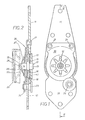
- 1 and 3 each have a fixed joint part 10 assigned to the seat part of a motor vehicle seat and a pivotable joint part 11 to be fastened to the backrest, these joint parts being pivotally connected to one another via a pivot axis 12.
- This pivot axis 12 has two central sections 13 and 14, between which there is a section designed as an eccentric 15. This eccentric is designed both in the exemplary embodiment shown in FIGS. 1 and 2 and in the exemplary embodiment shown in FIG.
- This spur gear 17 consists of an integral part of the hinge part 10 and, for example, manufactured by extrusion, in whose concentric center area the tapered bore 16 is arranged, the inclination of which corresponds to the cone of the eccentric.
- the pivotable joint part 11 has an internal ring gear 18, the tip circle diameter of which is at least one tooth height larger than the tip circle diameter of the spur gear 17.
- the number of teeth of the inner ring gear 18 is also at least one tooth larger than the number of teeth of the spur gear 17.
- This inner ring gear 18 of the joint part 11 is bridged by an integrally connected wall plate 19, which is supported on the central portion 13 of the pivot axis 12 concentrically with the inner ring gear 18 .
- a bearing plate 20 is fixedly connected to the pivotable joint part 11, for example by rivets 21, which overlaps the joint part 10 in the area of the spur gear 17 and encloses this between itself and the wall plate 19 of the joint part 11 on the central section 14 of the pivot axis 12 by means of a sliding bush 22 is stored.
- the axial cohesion of the joint parts is further served by a collar pin 23, which is riveted opposite the rivets 21 on the joint part 10 by means of a collar bushing 24, the head of the collar pin 23 overlapping the joint part 11 and the collar of the collar bushing 24 partially overlapping the end shield 20.
- the central section 14 protruding from the end shield 20 has, in the embodiment shown in FIGS. 1 and 2, at its end an annular groove 25 into which a retaining ring 26 engages, on which a spring washer 27 forming an energy store is supported at one end, which is supported on the other end, it is placed on end plate 20.
- An out-of-round pin 28 rises from the end face of the central section 14 adjacent to the annular groove 25, on which, for example, a handwheel 29 shown in broken lines can be fixed.
- a handwheel 29 shown in broken lines can be fixed.
- the truncated cone forming the eccentric 15 and the conical bore 16 surrounding it are inclined toward the pin 28.
- the static frictional forces supporting the action of the spring washer 27 decrease at the bearing points of the swivel axis, so that the axial force resulting from the radial force acting on the eccentric 15 is greater than the force of the spring washer 27 and the sliding frictional forces supporting it , whereby the pivot axis 12 together with its eccentric 15 is moved to the right from the locking position shown in FIG. 2 and the actuating movement is facilitated.
- the inclination of the eccentric 15 is to be selected such that the static friction angle is in the self-locking range.
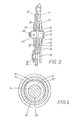
- the embodiment shown in FIG. 3 has some differences with respect to the embodiment shown in FIG. One of these differences is that the tapered bore 16 is located in a bush 30 which is inserted in a rotationally fixed manner in the spur gear 17. As a result, the coefficient of friction can be adjusted through the use of different materials, and through the appropriate choice of the width of the bushing 30, a full-area contact between the eccentric 15 and the tapered bore 16 can be achieved both in the case of support and in the case of movement.
- Another difference between the embodiment shown in FIG. 2 and the embodiment shown in FIG. 2 is that the conical bore 16 and the eccentric 15 designed as a truncated cone are tapered in the direction of the wall disk 19 of the internal gear 18.
- the end shield 20 remains free from the effects of axial forces, since these are absorbed directly by the joint part 11.
- the spring washer 27 forming the energy accumulator is supported at one end on the central section 13, if necessary, in turn via a locking ring 26 arranged in an annular groove 25, while the other end of the spring washer 27 is supported on the Wall disk 19 of the joint part 11 creates.
- the force ratios in the actuating movement and in the rest position of the swivel joint shown in FIG. 3 are analogous to those which also occur in the embodiment according to FIG.
- a conical surface area section 31 of the eccentric 15 is provided with a smaller curvature in the region of greatest eccentricity than the remaining conical surface area of the truncated cone forming the eccentric 15. This creates transition points 32 and 32 'on both sides of the longitudinal center of the pivot axis between the flatter conical surface section 31 and the rest of the conical surface, which together with the underside support line 33 form a three-point support on the central sections 13 and 14 of the pivot axis 12.
- the flattened conical surface section 31 extends essentially over an approximately 90 ° angular range.
Claims (5)
Priority Applications (8)
| Application Number | Priority Date | Filing Date | Title |
|---|---|---|---|
| EP80105654A EP0048294B1 (fr) | 1980-09-20 | 1980-09-20 | Ferrure d'articulation, en particulier pour sièges à dossier réglable |
| DE8080105654T DE3069977D1 (en) | 1980-09-20 | 1980-09-20 | Hinge unit, specially for seats with adjustable back rest |
| AU74327/81A AU547291B2 (en) | 1980-09-20 | 1981-08-19 | A hinge |
| ES1981268624U ES268624Y (es) | 1980-09-20 | 1981-08-24 | Dispositivo de articulacion de rotacion, en particular para asientos con respaldo regulable. |
| BR8105373A BR8105373A (pt) | 1980-09-20 | 1981-08-24 | Agriculacao giratoria em particular para assentos com espaldar ajustavel |
| ZA816057A ZA816057B (en) | 1980-09-20 | 1981-09-01 | A hinge,particularly for seats with adjustable backs |
| US06/298,755 US4453767A (en) | 1980-09-20 | 1981-09-02 | Hinge, particularly for seats with adjustable backs |
| JP56147985A JPS5784235A (en) | 1980-09-20 | 1981-09-21 | Turning gear |
Applications Claiming Priority (1)
| Application Number | Priority Date | Filing Date | Title |
|---|---|---|---|
| EP80105654A EP0048294B1 (fr) | 1980-09-20 | 1980-09-20 | Ferrure d'articulation, en particulier pour sièges à dossier réglable |
Publications (2)
| Publication Number | Publication Date |
|---|---|
| EP0048294A1 EP0048294A1 (fr) | 1982-03-31 |
| EP0048294B1 true EP0048294B1 (fr) | 1985-01-16 |
Family
ID=8186806
Family Applications (1)
| Application Number | Title | Priority Date | Filing Date |
|---|---|---|---|
| EP80105654A Expired EP0048294B1 (fr) | 1980-09-20 | 1980-09-20 | Ferrure d'articulation, en particulier pour sièges à dossier réglable |
Country Status (8)
| Country | Link |
|---|---|
| US (1) | US4453767A (fr) |
| EP (1) | EP0048294B1 (fr) |
| JP (1) | JPS5784235A (fr) |
| AU (1) | AU547291B2 (fr) |
| BR (1) | BR8105373A (fr) |
| DE (1) | DE3069977D1 (fr) |
| ES (1) | ES268624Y (fr) |
| ZA (1) | ZA816057B (fr) |
Cited By (1)
| Publication number | Priority date | Publication date | Assignee | Title |
|---|---|---|---|---|
| DE3919304A1 (de) * | 1988-06-14 | 1989-12-21 | Honda Motor Co Ltd | Verstellvorrichtung fuer die ruecklehne eines fahrzeugsitzes |
Families Citing this family (34)
| Publication number | Priority date | Publication date | Assignee | Title |
|---|---|---|---|---|
| JPS58103409A (ja) * | 1981-12-12 | 1983-06-20 | 三井金属鉱業株式会社 | 無段式角度調節機構 |
| DE3226714C2 (de) * | 1982-07-16 | 1986-09-18 | P.A. Rentrop, Hubbert & Wagner Fahrzeugausstattungen Gmbh & Co Kg, 3060 Stadthagen | Gelenkbeschlag für Kraftfahrzeugsitze mit verstellbarer Lehne |
| DE3227222C1 (de) * | 1982-07-21 | 1984-05-03 | Keiper Automobiltechnik Gmbh & Co Kg, 5630 Remscheid | Gelenkbeschlag fuer Sitze mit verstellbarer Rueckenlehne,insbesondere Kraftfahrzeugsitze |
| DE3319397C2 (de) * | 1983-05-28 | 1986-12-18 | P.A. Rentrop, Hubbert & Wagner Fahrzeugausstattungen Gmbh & Co Kg, 3060 Stadthagen | Gelenkbeschlag für einen Sitz mit verstellbarer Rückenlehne, insbesondere Kraftfahrzeugsitz |
| EP0159926B1 (fr) * | 1984-04-18 | 1987-06-24 | A. & M. Cousin et Cie | Articulations rondes utilisables pour les sièges de véhicules terrestres, nautiques et aériens |
| US4575153A (en) * | 1984-05-02 | 1986-03-11 | Tachikawa Spring Co. Ltd. | Back frame in a seat back for a vehicle seat |
| JPH0336291Y2 (fr) * | 1984-11-26 | 1991-08-01 | ||
| EP0209666B1 (fr) * | 1985-05-21 | 1990-03-14 | Aisin Seiki Kabushiki Kaisha | Moyens de réglage de position angulaire |
| EP0207182B1 (fr) * | 1985-07-02 | 1989-12-13 | KEIPER RECARO GmbH & Co. | Ferrure pivotante pour sièges à dossier réglable |
| DE3564667D1 (en) * | 1985-07-02 | 1988-10-06 | Keiper Recaro Gmbh Co | Hinge fitting for seats with an adjustable back rest, particularly for motor vehicle seats |
| DE3529887A1 (de) * | 1985-08-21 | 1987-03-05 | Keiper Recaro Gmbh Co | Gelenkbeschlag |
| DE3540727A1 (de) * | 1985-11-16 | 1987-05-21 | Keiper Recaro Gmbh Co | Stellantriebsvorrichtung fuer sitze, insbesondere kraftfahrzeugsitze |
| DE3616832A1 (de) * | 1986-05-17 | 1987-11-19 | Keiper Recaro Gmbh Co | Gelenkbeschlag fuer sitze, insbesondere kraftfahrzeugsitze |
| JPS62281908A (ja) * | 1986-05-30 | 1987-12-07 | 白木金属工業株式会社 | リクライニング装置 |
| JPH0438748Y2 (fr) * | 1986-07-18 | 1992-09-10 | ||
| FR2607761B1 (fr) * | 1986-12-03 | 1990-08-17 | Tubauto | Articulation continue pour siege de vehicule a rattrapage automatique des jeux |
| DE3705116C2 (de) * | 1987-02-18 | 1996-08-14 | Keiper Recaro Gmbh Co | Verstellbeschlag für Sitze mit neigungsveränderbarer Rückenlehne |
| DE3709403A1 (de) * | 1987-03-21 | 1988-09-29 | Keiper Recaro Gmbh Co | Drehgelenk, insbesondere fuer sitze mit verstellbarer lehne |
| DE8705554U1 (fr) * | 1987-04-14 | 1987-06-04 | Keiper Recaro Gmbh & Co, 5630 Remscheid, De | |
| DE3723204C2 (de) * | 1987-07-14 | 1998-02-12 | Keiper Gmbh & Co | Verstellvorrichtung für einen Sitz, insbesondere Kraftfahrzeugsitz, zur Neigungseinstellung der Rückenlehne |
| DE3723710C2 (de) * | 1987-07-17 | 1996-08-14 | Keiper Recaro Gmbh Co | Verstellbeschlag für Sitze mit verstellbarer Rückenlehne |
| DE3726433A1 (de) * | 1987-08-08 | 1989-02-16 | Keiper Recaro Gmbh Co | Gelenkbeschlag fuer sitze, insbesondere kraftfahrzeugsitze mit verstellbarer rueckenlehne |
| DE3744454A1 (de) * | 1987-12-29 | 1989-07-13 | Shiroki Corp | Ruecklehnwinkeleinstellvorrichtung |
| US4943116A (en) * | 1987-12-29 | 1990-07-24 | Akira Ohwada | Reclining angle adjustment device |
| AU598088B2 (en) * | 1988-01-13 | 1990-06-14 | Shiroki Kinzoku Kogyo Kabushiki Kaisha | Reclining angle adjustment device |
| GB8805290D0 (en) * | 1988-03-05 | 1988-04-07 | Ihw Eng Ltd | Seat reclining mechanism |
| FR2649943B1 (fr) * | 1989-07-24 | 1991-10-18 | Cousin Freres Sa | Dispositif permettant la compensation des jeux entre satellite et dentures des flasques de mecanismes reducteurs pour le reglage des positions des sieges, en particulier de sieges d'automobiles |
| DE4018819A1 (de) * | 1990-06-12 | 1991-12-19 | Rentrop Hubbert & Wagner | Gelenkbeschlag fuer sitze mit verstellbarer rueckenlehne |
| JP3196290B2 (ja) * | 1992-02-28 | 2001-08-06 | アイシン精機株式会社 | シートリクライニング装置 |
| DE4228054C2 (de) * | 1992-08-24 | 1994-07-14 | Keiper Recaro Gmbh Co | Verstellvorrichtung, insbesondere Gelenkbeschlag für Sitze mit verstellbarer Lehne |
| US5524970A (en) * | 1994-08-10 | 1996-06-11 | Hoover Universal, Inc. | Rotary recliner |
| AU2001293584A1 (en) * | 2000-09-29 | 2002-04-08 | Intier Automotive Inc. | Planocentric disc recliner |
| US20060025270A1 (en) * | 2004-07-27 | 2006-02-02 | Van De Geer Bernardus W G | Constantly engaged rotary recliner mechanism |
| JP2020118235A (ja) * | 2019-01-24 | 2020-08-06 | シロキ工業株式会社 | 減速装置 |
Family Cites Families (7)
| Publication number | Priority date | Publication date | Assignee | Title |
|---|---|---|---|---|
| FR1086102A (fr) * | 1953-10-29 | 1955-02-09 | Mécanisme réducteur variateur de vitesse | |
| GB803339A (en) * | 1953-12-17 | 1958-10-22 | Robert Henry Johnston | Improvements in or relating to gearing |
| DE1239951B (de) * | 1961-12-07 | 1967-05-03 | Recaro G M B H & Co | Gelenkbeschlag fuer Sitze mit verstellbarer Lehne, insbesondere fuer Kraftfahrzeuge |
| DE1242948B (de) * | 1960-03-22 | 1967-06-22 | Johanna Ludwig Geb Henning | Einstellbares Gelenk |
| FR1284061A (fr) * | 1960-12-31 | 1962-02-09 | Faure Bertrand Ets | Perfectionnements apportés aux dispositifs d'articulation pour sièges, notamment pour sièges d'automobiles |
| DE2028723A1 (de) * | 1970-06-11 | 1971-12-16 | Daimler Benz Ag, 7000 Stuttgart | Vorrichtung zum Verstellen der Neigung einer Ruckenlehne |
| DE2326223C3 (de) * | 1973-05-23 | 1979-10-31 | Keiper Automobiltechnik Gmbh & Co Kg, 5630 Remscheid | Gelenkbeschlag für Sitze mit verstellbarer Lehne, insbesondere Kraftfahrzeugsitze |
-
1980
- 1980-09-20 EP EP80105654A patent/EP0048294B1/fr not_active Expired
- 1980-09-20 DE DE8080105654T patent/DE3069977D1/de not_active Expired
-
1981
- 1981-08-19 AU AU74327/81A patent/AU547291B2/en not_active Ceased
- 1981-08-24 ES ES1981268624U patent/ES268624Y/es not_active Expired
- 1981-08-24 BR BR8105373A patent/BR8105373A/pt not_active IP Right Cessation
- 1981-09-01 ZA ZA816057A patent/ZA816057B/xx unknown
- 1981-09-02 US US06/298,755 patent/US4453767A/en not_active Expired - Lifetime
- 1981-09-21 JP JP56147985A patent/JPS5784235A/ja active Granted
Cited By (1)
| Publication number | Priority date | Publication date | Assignee | Title |
|---|---|---|---|---|
| DE3919304A1 (de) * | 1988-06-14 | 1989-12-21 | Honda Motor Co Ltd | Verstellvorrichtung fuer die ruecklehne eines fahrzeugsitzes |
Also Published As
| Publication number | Publication date |
|---|---|
| DE3069977D1 (en) | 1985-02-28 |
| AU547291B2 (en) | 1985-10-17 |
| JPS5784235A (en) | 1982-05-26 |
| EP0048294A1 (fr) | 1982-03-31 |
| ES268624U (es) | 1983-05-16 |
| JPS6132171B2 (fr) | 1986-07-25 |
| BR8105373A (pt) | 1982-05-11 |
| US4453767A (en) | 1984-06-12 |
| ES268624Y (es) | 1983-12-01 |
| ZA816057B (en) | 1982-08-25 |
| AU7432781A (en) | 1982-04-01 |
Similar Documents
| Publication | Publication Date | Title |
|---|---|---|
| EP0048294B1 (fr) | Ferrure d'articulation, en particulier pour sièges à dossier réglable | |
| EP0432420B1 (fr) | Articulation pour sièges à dossier réglable, en particulier pour sièges de véhicules automobiles | |
| DE3013304C2 (de) | Stellvorrichtung für Sitze und Fenster, insbesondere von Kraftfahrzeugen | |
| DE3624018C2 (de) | Lehnenneigungseinstellbeschlag für Sitze, insbesondere Kraftfahrzeugsitze | |
| DE4303819C2 (de) | Ver- und Feststellbeschlag für Sitze, insbesondere Kraftfahrzeugsitze | |
| EP0207183B1 (fr) | Ferrure d'articulation pour sièges à dossier réglable, en particulier pour sièges de véhicule automobile | |
| DE3723204C2 (de) | Verstellvorrichtung für einen Sitz, insbesondere Kraftfahrzeugsitz, zur Neigungseinstellung der Rückenlehne | |
| DE2326223B2 (de) | Gelenkbeschlag für Sitze mit verstellbarer Lehne, insbesondere Kraftfahrzeugsitze | |
| DE3709403C2 (fr) | ||
| EP0099549B1 (fr) | Ferrure articulée pour sièges de véhicules avec dossier réglable | |
| DE2854636A1 (de) | Gelenkbeschlag fuer sitze mit verstellbarer rueckenlehne, insbesondere kraftfahrzeugsitze | |
| DE3225546A1 (de) | Vorrichtung zur hoehenverstellung von sitzen, insbesondere kraftfahrzeugsitzen | |
| DE3923966A1 (de) | Gelenkbeschlag fuer sitze, insbesondere kraftfahrzeugsitze mit verstellbarer und freischwenkbarer rueckenlehne | |
| DE3223707A1 (de) | Gelenkbeschlag fuer sitze mit verstellbarer rueckenlehne, insbesondere kraftfahrzeugsitze | |
| DE3816510C2 (de) | Drehgelenk für Sitze, insbesondere Kraftfahrzeugsitze mit verstellbarer Lehne | |
| EP1375803A1 (fr) | Charnière de porte notamment pour véhicules automobile | |
| DE19533453A1 (de) | Beschlag zur Neigungseinstellung der Rückenlehne eines Sitzes, insbesondere eines Kraftfahrzeugsitzes | |
| DE3540726C2 (de) | Einstellbeschlag für Sitze mit neigungseinstellbarer Lehne, insbesondere für Kraftfahrzeugsitze | |
| DE1929412C3 (de) | Sitz, insbesondere Kraftfahrzeugsitz | |
| DE8025286U1 (de) | Drehgelenk, insbesondere für Sitze mit verstellbarer Lehne | |
| DE2032833A1 (de) | Vorrichtung zum Feststellen eines ver stellbaren Fahrzeugsitzes oder der schwenk baren Ruckenlehne eines Fahrzeugsitzes in wahlbarer Position | |
| DE2228842C3 (de) | Gelenkbeschlag für Fahrzeugsitze | |
| DE3401646A1 (de) | Drehgelenk, insbesondere fuer sitze mit verstellbarer rueckenlehne | |
| DE102020123963A1 (de) | Lehneneinstellbeschlag mit einer Ver- und Entriegelungseinrichtung umfassend zwei unabhängig voneinander einstellbare Verriegelungsmechanismen | |
| DE1580540C (de) | Gelenkbeschlag fur Sitze mit verstell barer Lehne, insbesondere Kraftfahrzeug sitze |
Legal Events
| Date | Code | Title | Description |
|---|---|---|---|
| PUAI | Public reference made under article 153(3) epc to a published international application that has entered the european phase |
Free format text: ORIGINAL CODE: 0009012 |
|
| AK | Designated contracting states |
Designated state(s): DE FR GB IT |
|
| 17P | Request for examination filed |
Effective date: 19820308 |
|
| ITF | It: translation for a ep patent filed |
Owner name: CALVANI SALVI E VERONELLI S.R.L. |
|
| RAP1 | Party data changed (applicant data changed or rights of an application transferred) |
Owner name: KEIPER RECARO GMBH & CO. |
|
| GRAA | (expected) grant |
Free format text: ORIGINAL CODE: 0009210 |
|
| AK | Designated contracting states |
Designated state(s): DE FR GB IT |
|
| REF | Corresponds to: |
Ref document number: 3069977 Country of ref document: DE Date of ref document: 19850228 |
|
| ET | Fr: translation filed | ||
| PLBE | No opposition filed within time limit |
Free format text: ORIGINAL CODE: 0009261 |
|
| STAA | Information on the status of an ep patent application or granted ep patent |
Free format text: STATUS: NO OPPOSITION FILED WITHIN TIME LIMIT |
|
| 26N | No opposition filed | ||
| ITTA | It: last paid annual fee | ||
| REG | Reference to a national code |
Ref country code: FR Ref legal event code: CD |
|
| PGFP | Annual fee paid to national office [announced via postgrant information from national office to epo] |
Ref country code: FR Payment date: 19980730 Year of fee payment: 19 |
|
| PGFP | Annual fee paid to national office [announced via postgrant information from national office to epo] |
Ref country code: DE Payment date: 19980827 Year of fee payment: 19 |
|
| PGFP | Annual fee paid to national office [announced via postgrant information from national office to epo] |
Ref country code: GB Payment date: 19990917 Year of fee payment: 20 |
|
| PG25 | Lapsed in a contracting state [announced via postgrant information from national office to epo] |
Ref country code: FR Free format text: LAPSE BECAUSE OF NON-PAYMENT OF DUE FEES Effective date: 20000531 |
|
| REG | Reference to a national code |
Ref country code: FR Ref legal event code: CA |
|
| PG25 | Lapsed in a contracting state [announced via postgrant information from national office to epo] |
Ref country code: DE Free format text: LAPSE BECAUSE OF NON-PAYMENT OF DUE FEES Effective date: 20000701 |
|
| REG | Reference to a national code |
Ref country code: FR Ref legal event code: ST |
|
| PG25 | Lapsed in a contracting state [announced via postgrant information from national office to epo] |
Ref country code: GB Free format text: LAPSE BECAUSE OF EXPIRATION OF PROTECTION Effective date: 20000919 |
|
| REG | Reference to a national code |
Ref country code: GB Ref legal event code: PE20 Effective date: 20000919 |