EP0048294B1 - Hinge unit, specially for seats with adjustable back rest - Google Patents
Hinge unit, specially for seats with adjustable back rest Download PDFInfo
- Publication number
- EP0048294B1 EP0048294B1 EP80105654A EP80105654A EP0048294B1 EP 0048294 B1 EP0048294 B1 EP 0048294B1 EP 80105654 A EP80105654 A EP 80105654A EP 80105654 A EP80105654 A EP 80105654A EP 0048294 B1 EP0048294 B1 EP 0048294B1
- Authority
- EP
- European Patent Office
- Prior art keywords
- eccentric
- hinge
- cone
- conical bore
- angle
- Prior art date
- Legal status (The legal status is an assumption and is not a legal conclusion. Google has not performed a legal analysis and makes no representation as to the accuracy of the status listed.)
- Expired
Links
Images
Classifications
-
- B—PERFORMING OPERATIONS; TRANSPORTING
- B60—VEHICLES IN GENERAL
- B60N—SEATS SPECIALLY ADAPTED FOR VEHICLES; VEHICLE PASSENGER ACCOMMODATION NOT OTHERWISE PROVIDED FOR
- B60N2/00—Seats specially adapted for vehicles; Arrangement or mounting of seats in vehicles
- B60N2/02—Seats specially adapted for vehicles; Arrangement or mounting of seats in vehicles the seat or part thereof being movable, e.g. adjustable
- B60N2/22—Seats specially adapted for vehicles; Arrangement or mounting of seats in vehicles the seat or part thereof being movable, e.g. adjustable the back-rest being adjustable
- B60N2/225—Seats specially adapted for vehicles; Arrangement or mounting of seats in vehicles the seat or part thereof being movable, e.g. adjustable the back-rest being adjustable by cycloidal or planetary mechanisms
- B60N2/2252—Seats specially adapted for vehicles; Arrangement or mounting of seats in vehicles the seat or part thereof being movable, e.g. adjustable the back-rest being adjustable by cycloidal or planetary mechanisms in which the central axis of the gearing lies inside the periphery of an orbital gear, e.g. one gear without sun gear
Definitions
- the invention relates to a swivel joint, in particular for seats with an adjustable backrest, in which two joint parts which can be moved relative to one another are connected to one another via a swivel axis, one of which determines the position of the two joint parts relative to one another and is designed as a transmission with at least one spur gear-internal gear pairing Locking device is provided which has an eccentric arranged on the swivel axis and rotatable therewith with an inclined surface which bears against the mounting surface of a bearing point associated with the gear wheel mounted on the eccentric and the swivel axis together with its eccentric by means of a force accumulator for generating a radial displacement between the two joint parts is movable in the axial direction.
- one of the two joint parts is connected to a seat part and the other joint part is connected to a backrest.
- the joint part connected to the seat part is in turn non-rotatably connected to a spur gear which meshes with an internal gear which is connected to the joint part associated with the backrest in a rotationally fixed connection.
- This joint part belonging to the backrest is supported on central sections of a swivel axis, on the eccentric section of which the spur gear is supported with the interposition of bushings.
- the eccentric section of the pivot axis has a wedge-like footprint, which is adjacent to guide surfaces running perpendicular to it.
- This eccentric section is surrounded by a ring which has in its interior lateral guide surfaces which match the eccentric section and also an inner wedge-like positioning surface.
- the eccentric section is loaded in such a way by a force accumulator, which is fixed in the axial direction on a central section of the swivel axis, that the toothings of the spur gear and the internal ring gear are pressed into one another via the ring surrounding the latter. This eliminates on the one hand the play of the toothing and on the other hand the bearing play between the swivel axis and the joint parts. In this state, the pivoting of the joint parts is very difficult, since the friction forces are significantly increased due to the tension.
- a lifting cam device is arranged between the central section of the pivot axis and the actuating handle arranged thereon, with which the pivot axis is displaced in the axial direction against the action of the energy accumulator in the release direction against the action of the energy store.
- the effective eccentricity of the eccentric bushing surrounding the eccentric section is reduced to such an extent that there is a tooth play that ensures smooth adjustment of the spur gear in the internal gear.
- the radial play can be eliminated in the event of a lock, but the required axial displacement of the swivel axis is only achieved by the lifting cam device which represents additional means.
- the clamping position does not automatically reset itself by simply releasing the position handle, but the operator has to turn the position handle in a movement opposite to the actual position movement after completion of the actual positioning movement in order to compensate for the radial play in the event of a finding.
- the object of the invention is to provide a swivel joint in which the eccentricity of the eccentric can be changed on the one hand for smooth adjustment during the actuating movement and on the other hand for eliminating the radial play of the swivel joint during its locking position, without the user of the seat having a special one for eliminating the radial play
- the actuating movement must be initiated in the swivel axis.
- the eccentric is designed as a truncated cone and the bearing point surrounding the eccentric has a tapered bore that matches the inclination of the truncated cone, the angle of inclination of which is smaller than the static friction angle and greater than the sliding friction angle of the bearing pair, and that the eccentric is from Lift mechanism is acted on in the direction of the tapered bore.
- a brake shaft is used, on the one hand a gear meshing with the pivotable joint part and on the other hand a truncated cone is arranged.
- this truncated cone is neither part of the pivot axis nor of an eccentric, because this known swivel does not have an eccentric.
- the truncated cone of the brake shaft forms a brake device with a tapered sleeve held on the fixed joint part, which, when solved by a handle, allows the joint part connected to the backrest to be quickly adjusted by the backrest being pivoted by the seat user in one sense or another.
- the known radial joint does not eliminate the radial play composed of backlash and bearing play.
- the swivel joint according to the invention is explained using the exemplary embodiment of a joint fitting suitable for motor vehicle seats.
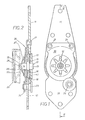
- 1 and 3 each have a fixed joint part 10 assigned to the seat part of a motor vehicle seat and a pivotable joint part 11 to be fastened to the backrest, these joint parts being pivotally connected to one another via a pivot axis 12.
- This pivot axis 12 has two central sections 13 and 14, between which there is a section designed as an eccentric 15. This eccentric is designed both in the exemplary embodiment shown in FIGS. 1 and 2 and in the exemplary embodiment shown in FIG.
- This spur gear 17 consists of an integral part of the hinge part 10 and, for example, manufactured by extrusion, in whose concentric center area the tapered bore 16 is arranged, the inclination of which corresponds to the cone of the eccentric.
- the pivotable joint part 11 has an internal ring gear 18, the tip circle diameter of which is at least one tooth height larger than the tip circle diameter of the spur gear 17.
- the number of teeth of the inner ring gear 18 is also at least one tooth larger than the number of teeth of the spur gear 17.
- This inner ring gear 18 of the joint part 11 is bridged by an integrally connected wall plate 19, which is supported on the central portion 13 of the pivot axis 12 concentrically with the inner ring gear 18 .
- a bearing plate 20 is fixedly connected to the pivotable joint part 11, for example by rivets 21, which overlaps the joint part 10 in the area of the spur gear 17 and encloses this between itself and the wall plate 19 of the joint part 11 on the central section 14 of the pivot axis 12 by means of a sliding bush 22 is stored.
- the axial cohesion of the joint parts is further served by a collar pin 23, which is riveted opposite the rivets 21 on the joint part 10 by means of a collar bushing 24, the head of the collar pin 23 overlapping the joint part 11 and the collar of the collar bushing 24 partially overlapping the end shield 20.
- the central section 14 protruding from the end shield 20 has, in the embodiment shown in FIGS. 1 and 2, at its end an annular groove 25 into which a retaining ring 26 engages, on which a spring washer 27 forming an energy store is supported at one end, which is supported on the other end, it is placed on end plate 20.
- An out-of-round pin 28 rises from the end face of the central section 14 adjacent to the annular groove 25, on which, for example, a handwheel 29 shown in broken lines can be fixed.
- a handwheel 29 shown in broken lines can be fixed.
- the truncated cone forming the eccentric 15 and the conical bore 16 surrounding it are inclined toward the pin 28.
- the static frictional forces supporting the action of the spring washer 27 decrease at the bearing points of the swivel axis, so that the axial force resulting from the radial force acting on the eccentric 15 is greater than the force of the spring washer 27 and the sliding frictional forces supporting it , whereby the pivot axis 12 together with its eccentric 15 is moved to the right from the locking position shown in FIG. 2 and the actuating movement is facilitated.
- the inclination of the eccentric 15 is to be selected such that the static friction angle is in the self-locking range.
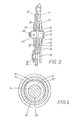
- the embodiment shown in FIG. 3 has some differences with respect to the embodiment shown in FIG. One of these differences is that the tapered bore 16 is located in a bush 30 which is inserted in a rotationally fixed manner in the spur gear 17. As a result, the coefficient of friction can be adjusted through the use of different materials, and through the appropriate choice of the width of the bushing 30, a full-area contact between the eccentric 15 and the tapered bore 16 can be achieved both in the case of support and in the case of movement.
- Another difference between the embodiment shown in FIG. 2 and the embodiment shown in FIG. 2 is that the conical bore 16 and the eccentric 15 designed as a truncated cone are tapered in the direction of the wall disk 19 of the internal gear 18.
- the end shield 20 remains free from the effects of axial forces, since these are absorbed directly by the joint part 11.
- the spring washer 27 forming the energy accumulator is supported at one end on the central section 13, if necessary, in turn via a locking ring 26 arranged in an annular groove 25, while the other end of the spring washer 27 is supported on the Wall disk 19 of the joint part 11 creates.
- the force ratios in the actuating movement and in the rest position of the swivel joint shown in FIG. 3 are analogous to those which also occur in the embodiment according to FIG.
- a conical surface area section 31 of the eccentric 15 is provided with a smaller curvature in the region of greatest eccentricity than the remaining conical surface area of the truncated cone forming the eccentric 15. This creates transition points 32 and 32 'on both sides of the longitudinal center of the pivot axis between the flatter conical surface section 31 and the rest of the conical surface, which together with the underside support line 33 form a three-point support on the central sections 13 and 14 of the pivot axis 12.
- the flattened conical surface section 31 extends essentially over an approximately 90 ° angular range.
Description
Die Erfindung betrifft ein Drehgelenk, insbesondere für Sitze mit verstellbarer Lehne, bei dem zwei gegeneinander bewegbare Gelenkteile über eine Schwenkachse miteinander verbunden sind, wobei eine die Lage der beiden Gelenkteile zueinander bestimmende, als Getriebe mit wenigstens einer Stirnrad-Innenzahnrad-Paarung ausgebildete Ver- und Feststelleinrichtung vorgesehen ist, die einen auf der Schwenkachse angeordneten und mit dieser drehbaren Exzenter mit einer geneigten Fläche aufweist, die an der Stellfläche einer dem auf dem Exzenter gelagerten Getrieberad zugeordneten Lagerstelle anliegt und die Schwenkachse zusammen mit ihrem Exzenter mittels eines Kraftspeichers zur Erzeugung einer Radialverschiebung zwischen den beiden Gelenkteilen in axialer Richtung bewegbar ist.The invention relates to a swivel joint, in particular for seats with an adjustable backrest, in which two joint parts which can be moved relative to one another are connected to one another via a swivel axis, one of which determines the position of the two joint parts relative to one another and is designed as a transmission with at least one spur gear-internal gear pairing Locking device is provided which has an eccentric arranged on the swivel axis and rotatable therewith with an inclined surface which bears against the mounting surface of a bearing point associated with the gear wheel mounted on the eccentric and the swivel axis together with its eccentric by means of a force accumulator for generating a radial displacement between the two joint parts is movable in the axial direction.
Bei einem derartigen aus der DE-AS 2326223 bekannten Drehgelenk ist einer der beiden Gelenkteile mit einem Sitzteil und der andere Gelenkteil mit einer Rückenlehne verbunden. Der mit dem Sitzteil verbundene Gelenkteil ist seinerseits wiederum drehfest mit einem Stirnrad verbunden, welches mit einem Innenzahnrad kämmt, das mit dem der Rückenlehne zugehörigen Gelenkteil in drehfester Verbindung steht. Dieser der Rückenlehne zugehörige Gelenkteil stützt sich auf zentrischen Abschnitten einer Schwenkachse ab, auf deren exzentrischem Abschnitt das Stirnrad unter Zwischenschaltung von Buchsen gelagert ist. Der exzentrische Abschnitt der Schwenkachse weist im Bereich seiner grössten Exzentrizität eine keilartige Stellfläche auf, der senkrecht dazu verlaufende Führungsflächen benachbart sind. Dieser Exzenterabschnitt ist von einem Ring umgeben, der in seinem Inneren zum Exzenterabschnitt passende seitliche Führungsflächen und auch eine innere keilartige Stellfläche aufweist. Durch einen an einem zentrischen Abschnitt der Schwenkachse in axialer Richtung festgelegten Kraftspeicher ist der Exzenterabschnitt derart belastet, dass über den diesen umgebenden Ring die Verzahnungen von Stirnrad und Innenzahnkranz ineinandergepresst werden. Dadurch wird einerseits das Spiel der Verzahnung und andererseits das Lagerspiel zwischen der Schwenkachse und den Gelenkteilen eliminiert. In diesem Zustand ist die Verschwenkung der Gelenkteile sehr schwergängig, da infolge der Verspannung die Reibkräfte wesentlich erhöhnt sind. Aus diesem Grund ist zwischen dem zentrischen Abschnitt der Schwenkachse und der darauf angeordneten Stellhandhabe eine Hubnockeneinrichtung angeordnet, mit welcher zu Beginn der Stellbewegung am Drehgriff die Schwenkachse entgegen der Wirkung des Kraftspeichers in axialer Richtung im Lösesinne verschoben wird. Dadurch verringert sich die wirksame Exzentrizität der den Exzenterabschnitt umgebenden Exzenterbuchse so weit, dass ein ein leichtgängiges Verstellen des Stirnrades in dem Innenzahnrad gewährleistendes Zahnspiel gegeben ist. Nach dem Stellvorgang ist die Stellhandhabe geringfügig zurückzudrehen, um die Hubnockeneinrichtung in ihre Ausgangslage zurückzustellen, so dass der Kraftspeicher die Schwenkachse mit dem Exzenterabschnitt in eine Radialspiel eliminierende Spannlage zurückführt. Bei diesem bekannten Drehgelenk lässt sich zwar das Radialspiel im Feststellfall eliminieren, jedoch wird die dafür erforderliche Axialverschiebung der Schwenkachse nur durch die zusätzliche Mittel darstellende Hubnockeneinrichtung erzielt. Ausserdem stellt sich die Spannlage nicht durch blosses Loslassen der Stellenhandhabe selbsttätig wieder ein, sondern die Bedienungsperson hat nach Abschluss der eigentlichen Stellbewegung die Stellhandhabe in einer der eigentlichen Stellbewegung entgegenstehenden Bewegung zurückzudrehen, um im Feststellfall das Radialspiel auszugleichen.In such a swivel joint known from DE-AS 2326223, one of the two joint parts is connected to a seat part and the other joint part is connected to a backrest. The joint part connected to the seat part is in turn non-rotatably connected to a spur gear which meshes with an internal gear which is connected to the joint part associated with the backrest in a rotationally fixed connection. This joint part belonging to the backrest is supported on central sections of a swivel axis, on the eccentric section of which the spur gear is supported with the interposition of bushings. In the area of its greatest eccentricity, the eccentric section of the pivot axis has a wedge-like footprint, which is adjacent to guide surfaces running perpendicular to it. This eccentric section is surrounded by a ring which has in its interior lateral guide surfaces which match the eccentric section and also an inner wedge-like positioning surface. The eccentric section is loaded in such a way by a force accumulator, which is fixed in the axial direction on a central section of the swivel axis, that the toothings of the spur gear and the internal ring gear are pressed into one another via the ring surrounding the latter. This eliminates on the one hand the play of the toothing and on the other hand the bearing play between the swivel axis and the joint parts. In this state, the pivoting of the joint parts is very difficult, since the friction forces are significantly increased due to the tension. For this reason, a lifting cam device is arranged between the central section of the pivot axis and the actuating handle arranged thereon, with which the pivot axis is displaced in the axial direction against the action of the energy accumulator in the release direction against the action of the energy store. As a result, the effective eccentricity of the eccentric bushing surrounding the eccentric section is reduced to such an extent that there is a tooth play that ensures smooth adjustment of the spur gear in the internal gear. After the actuating process, the actuating handle is to be turned back slightly in order to return the lifting cam device to its initial position, so that the energy accumulator returns the pivot axis with the eccentric section to a clamping position which eliminates radial play. With this known rotary joint, the radial play can be eliminated in the event of a lock, but the required axial displacement of the swivel axis is only achieved by the lifting cam device which represents additional means. In addition, the clamping position does not automatically reset itself by simply releasing the position handle, but the operator has to turn the position handle in a movement opposite to the actual position movement after completion of the actual positioning movement in order to compensate for the radial play in the event of a finding.
Die Aufgabe der Erfindung besteht darin, ein Drehgelenk zu schaffen, bei dem die Exzentrizität des Exzenters einerseits zur leichtgängigen Verstellung während der Stellbewegung und andererseits zur Eliminierung des Radialspieles des Drehgelenkes während seiner Feststellage veränderbar ist, ohne dass vom Sitzbenutzer zur Eliminierung des Radialspiels eine dafür besondere Stellbewegung in die Schwenkachse einzuleiten ist.The object of the invention is to provide a swivel joint in which the eccentricity of the eccentric can be changed on the one hand for smooth adjustment during the actuating movement and on the other hand for eliminating the radial play of the swivel joint during its locking position, without the user of the seat having a special one for eliminating the radial play The actuating movement must be initiated in the swivel axis.
Diese Aufgabe ist erfindungsgemäss dadurch gelöst, dass der Exzenter als Kegelstumpf ausgebildet ist und die den Exzenter umgebende Lagerstelle eine mit der Neigung des Kegelstumpfes übereinstimmende Kegelbohrung aufweist, deren Neigungswinkel kleiner als der Haftreibwinkel und grösser als der Gleitreibwinkel der Lagerpaarung ist, und dass der Exzenter vom Kraftspeicher in Richtung auf die Kegelbohrung beaufschlagt ist.This object is achieved according to the invention in that the eccentric is designed as a truncated cone and the bearing point surrounding the eccentric has a tapered bore that matches the inclination of the truncated cone, the angle of inclination of which is smaller than the static friction angle and greater than the sliding friction angle of the bearing pair, and that the eccentric is from Lift mechanism is acted on in the direction of the tapered bore.
Bei einem aus der FR-A 1 284061 bekannten Drehgelenk ist eine Bremswelle eingesetzt, auf welcher einerseits ein mit dem schwenkbaren Gelenkteil kämmendes Zahnrad und andererseits ein Kegelstumpf angeordnet ist. Dieser Kegelstumpf ist jedoch weder Bestandteil der Schwenkachse noch eines Exzenters, denn einen Exzenter weist dieses bekannte Drehgelenk nicht auf. Der Kegelstumpf der Bremswelle bildet mit einer am festen Gelenkteil gehalterten Kegelhülse eine Bremseinrichtung, die bei Lösung durch eine Handhabe eine Schnellverstellung des mit der Rückenlehne verbundenen Gelenkteiles erlaubt, indem die Rückenlehne vom Sitzbenutzer im einen oder anderen Sinn verschwenkt werden kann. Eine Eliminierung des sich aus Zahnflankenspiel und Lagerspiel zusammensetzenden Radialspieles erfolgt bei dem bekannten Drehgelenk nicht.In a rotary joint known from FR-A 1 284061, a brake shaft is used, on the one hand a gear meshing with the pivotable joint part and on the other hand a truncated cone is arranged. However, this truncated cone is neither part of the pivot axis nor of an eccentric, because this known swivel does not have an eccentric. The truncated cone of the brake shaft forms a brake device with a tapered sleeve held on the fixed joint part, which, when solved by a handle, allows the joint part connected to the backrest to be quickly adjusted by the backrest being pivoted by the seat user in one sense or another. The known radial joint does not eliminate the radial play composed of backlash and bearing play.
Die mit der Erfindung erzielten Vorteile sind darin zu sehen, dass durch die Überwindung der Haftreibung im Stellfall Gleitreibungskräfte wirksam sind, die beim Verstellen des Exzenters zusammen mit der Rückstellkraft des Kraftspeichers kleiner sind, als die aus den Radialkräften resultierende Axialkraft, wodurch der Exzenter im Sinne eines Radialspieles axial verschoben wird. Diese Axialkraftwirkung kehrt sich bei Unterbrechung bzw. Beendigung der Stellenbewegung um, da die Haftreibungskräfte dann grösser sind und zusammen mit der Federkraft die aus der Radialkraft resultierende Axialkraft überwinden, so dass der Exzenterabschnitt im Sinne einer Eliminierung des Radialspieles zurückgeschoben wird. Durch die Axialbewegung des Exzenterabschnittes der Schwenkachse ist ein Ausgleich der unvermeidlichen Fertigungstoleranzen möglich. Somit sind Mittel zur Aufrechterhaltung eines Spieles zur leichteren Verstellung entbehrlich, da sich dieses Spiel bei der Verstellung selbst einstellt. Ein besonderes Augenmerk braucht der Sitzbenutzer nach der Betätigung des Drehgelenkes nicht auf den Radialspielausgleich nach der Beendigung der Stellbewegung zu richten, da das Radialspiel sich ebenfalls selbsttätig nach Beendigung der Stellbewegung eliminiert. Weitere Vorteile ergeben sich durch die in den Unteransprüchen genannten Merkmale. So wird eine stabile Lage zwischen dem Stirnrad und dem Innenzahnrad in der eingestellten Lage der Gelenkteile durch eine geringere Krümmung des Kegelmantelflächenabschnittes des Exzenters im Bereich seiner grössten Exzentrizität als an seiner übrigen Kegelmantelfläche erzielt. Dadurch ergibt sich eine sichere Dreipunktabstützung der Schwenkachse an zwei Stellen der Kegelmantelfläche und einem mittig dazu liegenden Abstützpunkt, der im anderen Gelenkteil gelagerten zentrischen Abschnitte der Schwenkachse.The advantages achieved by the invention can be seen in the fact that by overcoming the static friction, sliding friction forces are effective which, when the eccentric is adjusted together with the restoring force of the energy accumulator, are smaller than the axial force resulting from the radial forces, as a result of which the eccentric in Radial play is shifted axially. This axial force effect is reversed when the position movement is interrupted or ended, since the static friction forces are then greater and, together with the spring force, overcome the axial force resulting from the radial force, so that the eccentric section is pushed back in order to eliminate the radial play. The axial movement of the eccentric section of the swivel axis makes it possible to compensate for the inevitable manufacturing tolerances. Means for maintaining a game for easier adjustment are therefore unnecessary, since this game adjusts itself during the adjustment. After the actuation of the swivel joint, the seat user does not need to pay particular attention to the radial play compensation after the end of the actuating movement, since the radial play is also automatically eliminated after the end of the actuating movement. Further advantages result from the features mentioned in the subclaims. Thus, a stable position between the spur gear and the internal gear in the set position of the joint parts is achieved by a smaller curvature of the conical surface section of the eccentric in the region of its greatest eccentricity than on its other conical surface. This results in reliable three-point support of the swivel axis at two points on the conical lateral surface and a support point located centrally, the central sections of the swivel axis mounted in the other joint part.
Im folgenden ist die Erfindung anhand von lediglich zwei Ausführungsbeispiele darstellenden Zeichnungen näher erläutert.The invention is explained in more detail below with the aid of drawings showing only two exemplary embodiments.
Es zeigen:
- Fig. 1 ein Drehgelenk zur Verwendung zwischen Sitz und Rückenlehne eines Kraftfahrzeugsitzes in einer Seitenansicht, bei abgenommener Handhabe,
- Fig. 2 das aus Fig. 1 ersichtliche Drehgelenk in einem Längsschnitt nach der Linie II-II von Fig. 1,
- Fig. 3 ein weiteres Ausführungsbeispiel eines Drehgelenkes, dessen Gelenk ebenfalls in einem Längsschnitt dargestellt ist,
- Fig. 4 die Abstützung des Exzenterabschnittes in der Lagerstelle eines Gelenkteiles in einem Schnitt nach der Linie IV-IV von Fig. 3 in gegenüber dieser vergrössertem Massstab.
- 1 is a side view of a swivel joint for use between the seat and backrest of a motor vehicle seat, with the handle removed,
- 2 shows the rotary joint shown in FIG. 1 in a longitudinal section along the line II-II of FIG. 1,
- 3 shows another embodiment of a swivel joint, the joint of which is also shown in a longitudinal section,
- Fig. 4 shows the support of the eccentric section in the bearing point of a joint part in a section along the line IV-IV of Fig. 3 on an enlarged scale compared to this.
Das erfindungsgemässe Drehgelenk ist am Ausführungsbeispiel eines für Kraftfahrzeugsitze geeigneten Gelenkbeschlages erläutert. Dabei weisen die aus dem Fig. 1 und 3 ersichtlichen Gelenkbeschläge jeweils einen dem Sitzteil eines Kraftfahrzeugsitzes zugeordneten festen Gelenkteil 10 und einen an der Rückenlehne zu befestigenden, schwenkbaren Gelenkteil 11 auf, wobei diese Gelenkteile über eine Schwenkachse 12 drehgelenkig miteinander verbunden sind. Diese Schwenkachse 12 weist zwei zentrische Abschnitte 13 und 14 auf, zwischen denen sich ein als Exzenter 15 ausgebildeter Abschnitt befindet. Dieser Exzenter ist sowohl bei dem aus den Fig. 1 und 2 ersichtlichen Ausführungsbeispiel als auch aus dem aus Fig. 3 ersichtlichen Ausführungsbeispiel als Kegelstumpf ausgebildet, der von einer mit der Neigung des Kegelstumpfes übereinstimmenden Kegelbohrung 16 umfasst ist, die sich beispielsweise in dem Stirnrad 17 des festen Gelenkteiles 10 befindet. Dieses Stirnrad 17 besteht aus einer einstückig mit dem Gelenkteil 10 verbundenen und beispielsweise durch Fliesspressen hergestellten Wandscheibe, in deren zur Verzahnung konzentrischem Mittelpunktbereich die Kegelbohrung 16 angeordnet ist, deren Neigung dem Kegel des Exzenters entspricht. Der schwenkbare Gelenkteil 11 weist einen Innenzahnkranz 18 auf, dessen Kopfkreisdurchmesser um wenigstens eine Zahnhöhe grösser als der Kopfkreisdurchmesser des Stirnrades 17 ist. Auch die Zähnezahl des Innenzahnkranzes 18 ist um mindestens einen Zahn grösser als die Zähnezahl des Stirnrades 17. Dieser Innenzahnkranz 18 des Gelenkteiles 11 ist durch eine einstückig damit verbundene Wandscheibe 19 überbrückt, die sich auf dem zentrischen Abschnitt 13 der Schwenkachse 12 konzentrisch zum Innenzahnkranz 18 abstützt. Mit dem schwenkbaren Gelenkteil 11 ist ein Lagerschild 20 beispielsweise durch Niete 21 fest verbunden, der den Gelenkteil 10 in Bereich des Stirnrades 17 übergreifend und diesen zwischen sich und der Wandscheibe 19 des Gelenkteiles 11 einschliessend auf dem zentrischen Abschnitt 14 der Schwenkachse 12 mittels einer Gleitbuchse 22 gelagert ist. Dem axialen Zusammenhalt der Gelenkteile dient weiterhin ein Bundzapfen 23, der den Nieten 21 gegenüberliegend am Gelenkteil 10 mittels einer Kragenbuchse 24 vernietet ist, wobei der Kopf des Bundzapfens 23 den Gelenkteil 11 und der Kragen der Kragenbuchse 24 den Lagerschild 20 bereichsweise übergreifen. Der aus dem Lagerschild 20 ausragende zentrische Abschnitt 14 weist bei dem aus den Fig. 1 und 2 ersichtlichen Ausführungsbeispiel an seinem Ende eine Ringnut 25 auf, in welche ein Sicherungsring 26 eingreift, an dem sich eine einen Kraftspeicher bildende Federscheibe 27 einerends abstützt, die sich andernends am Lagerschild 20 anlegt. Aus der der Ringnut 25 benachbarten Stirnfläche des zentrischen Abschnitts 14 erhebt sich ein unrunder Zapfen 28, an dem beispielsweise ein in strichpunktierten Linien dargestelltes Handrad 29 festlegbar ist. Bei dem aus Fig. 2 ersichtlichen Ausführungsbeispiel ist der den Exzenter 15 bildende Kegelstumpf und die diesen umgebende Kegelbohrung 16 zum Zapfen 28 hin geneigt. Bei Einleitung einer Drehbewegung in die Schwenkachse 12 vermindern sich die die Wirkung der Federscheibe 27 unterstützenden Haftreibkräfte an den Lagerstellen der Schwenkachse, so dass die aus der auf den Exzenter 15 wirkende Radialkraft resultierende Axialkraft grösser ist als die Kraft der Federscheibe 27 und die diese unterstützenden Gleitreibungskräfte, wodurch die Schwenkachse 12 zusammen mit ihrem Exzenter 15 aus der in Fig.2 dargestellten Feststellage nach rechts bewegt wird und sich die Stellbewegung erleichtert. Dabei ist die Neigung des Exzenters 15 derart zu wählen, dass der Haftreibwinkel im Selbsthemmungsbereich liegt.The swivel joint according to the invention is explained using the exemplary embodiment of a joint fitting suitable for motor vehicle seats. 1 and 3 each have a fixed
Das aus Fig. 3 ersichtliche Ausführungsbeispiel weist im Hinblick auf die aus Fig. ersichtliche Ausführung einige Unterschiede auf. Einer dieser Unterschiede besteht darin, dass sich die kegelige Bohrung 16 in einer Buchse 30 befindet, die in das Stirnrad 17 drehfest eingesetzt ist. Dadurch lässt sich durch die Verwendung verschiedenartiger Werkstoffe der Reibwert anpassen, und durch entsprechende Breitenwahl der Buchse 30 sowohl im Stützfall als auch im Bewegungsfall eine ganzflächige Anlage zwischen dem Exzenter 15 und der Kegelbohrung 16 erzielen. Ein weiterer Unterschied der aus Fig. ersichtlichen Ausführungsform gegenüber der aus Fig. 2 ersichtlichen Ausführungsform besteht darin, dass die Kegelbohrung 16 sowie der als Kegelstumpf ausgebildete Exzenter 15 in Richtung auf die Wandscheibe 19 des Innenzahnrades 18 hin verjüngt ist. Dadurch bleibt der Lagerschild 20 von Axialkraftauswirkungen frei, da diese unmittelbar von dem Gelenkteil 11 aufgefangen werden. Dabei versteht es sich, dass bei der Ausführungsform gemäss Fig. 3 die den Kraftspeicher bildende Federscheibe 27 einerends auf dem zentrischen Abschnitt 13 ggfs. wiederum über einen in einer Ringnut 25 angeordneten Sicherungsring 26 abgestützt ist, während sich das andere Ende der Federscheibe 27 an der Wandscheibe 19 des Gelenkteiles 11 anlegt. Die Kraftverhältnisse bei der Stellbewegung und bei der Ruhelage des aus Fig. 3 ersichtlichen Drehgelenkes sind denen analog, die auch bei dem Ausführungsbeispiel nach Fig.2 auftreten.The embodiment shown in FIG. 3 has some differences with respect to the embodiment shown in FIG. One of these differences is that the
Um eine sichere Stützlage des Stirnrades auf der Schwenkachse zu erzielen, ist, wie in Fig. 4 dargestellt, ein Kegelmantelflächenabschnitt 31 des Exzenters 15 im Bereich der grössten Exzentrizität mit einer geringeren Krümmung versehen als die übrige Kegelmantelfläche des den Exzenter 15 bildenden Kegelstumpfes. Dadurch entstehen beiderseits der Längsmitte der Schwenkachse Übergangspunkte 32 und 32' zwischen dem flacher verlaufenden Kegelmantelflächenabschnitt 31 und der übrigen Kegelmantelfläche, die zusammen mit der unterseitigen Stützlinie 33 an den zentrischen Abschnitten 13 und 14 der Schwenkachse 12 eine Dreipunktabstützung bilden. Dabei erstreckt sich der abgeflachte Kegelmantelflächenabschnitt 31 im wesentlichen über einen etwa 90° grossen Winkelbereich.In order to achieve a secure support position of the spur gear on the pivot axis, as shown in FIG. 4, a conical
Es sind noch mancherlei andere Ausführungen und Ausgestaltungen der Erfindung möglich. So ist es beispielsweise auch denkbar, die kegelige Bohrung in der Wandscheibe 19 anzuordnen und den Exzenter 15 auf der Schwenkachse derart zu plazieren, dass dieser in die kegelige Bohrung in der Wandscheibe 19 fasst. Ausserdem ist der Verwendungszweck derartiger Drehgelenke nicht auf den Einsatz bei Fahrzeugsitzen beschränkt, sondern ein derartiges Drehgelenk lässt sich überall dort verwenden, wo Radialspiel zu eliminieren ist. Dies kann neben der Anwendung bei Fahrzeugsitzen für deren Verstellung auch für die Verstellung von Fensterscheiben, Kopfstützen od. dgl. bedeutungsvoll sein.Many other designs and configurations of the invention are possible. For example, it is also conceivable to arrange the conical bore in the
Claims (5)
Priority Applications (8)
| Application Number | Priority Date | Filing Date | Title |
|---|---|---|---|
| DE8080105654T DE3069977D1 (en) | 1980-09-20 | 1980-09-20 | Hinge unit, specially for seats with adjustable back rest |
| EP80105654A EP0048294B1 (en) | 1980-09-20 | 1980-09-20 | Hinge unit, specially for seats with adjustable back rest |
| AU74327/81A AU547291B2 (en) | 1980-09-20 | 1981-08-19 | A hinge |
| BR8105373A BR8105373A (en) | 1980-09-20 | 1981-08-24 | SPINNING AGRICULATION IN PARTICULAR FOR SEATS WITH ADJUSTABLE SPREAD |
| ES1981268624U ES268624Y (en) | 1980-09-20 | 1981-08-24 | ROTATION ARTICULATION DEVICE, IN PARTICULAR FOR SEATS WITH ADJUSTABLE BACKREST. |
| ZA816057A ZA816057B (en) | 1980-09-20 | 1981-09-01 | A hinge,particularly for seats with adjustable backs |
| US06/298,755 US4453767A (en) | 1980-09-20 | 1981-09-02 | Hinge, particularly for seats with adjustable backs |
| JP56147985A JPS5784235A (en) | 1980-09-20 | 1981-09-21 | Turning gear |
Applications Claiming Priority (1)
| Application Number | Priority Date | Filing Date | Title |
|---|---|---|---|
| EP80105654A EP0048294B1 (en) | 1980-09-20 | 1980-09-20 | Hinge unit, specially for seats with adjustable back rest |
Publications (2)
| Publication Number | Publication Date |
|---|---|
| EP0048294A1 EP0048294A1 (en) | 1982-03-31 |
| EP0048294B1 true EP0048294B1 (en) | 1985-01-16 |
Family
ID=8186806
Family Applications (1)
| Application Number | Title | Priority Date | Filing Date |
|---|---|---|---|
| EP80105654A Expired EP0048294B1 (en) | 1980-09-20 | 1980-09-20 | Hinge unit, specially for seats with adjustable back rest |
Country Status (8)
| Country | Link |
|---|---|
| US (1) | US4453767A (en) |
| EP (1) | EP0048294B1 (en) |
| JP (1) | JPS5784235A (en) |
| AU (1) | AU547291B2 (en) |
| BR (1) | BR8105373A (en) |
| DE (1) | DE3069977D1 (en) |
| ES (1) | ES268624Y (en) |
| ZA (1) | ZA816057B (en) |
Cited By (1)
| Publication number | Priority date | Publication date | Assignee | Title |
|---|---|---|---|---|
| DE3919304A1 (en) * | 1988-06-14 | 1989-12-21 | Honda Motor Co Ltd | ADJUSTMENT DEVICE FOR THE BACKREST OF A VEHICLE SEAT |
Families Citing this family (34)
| Publication number | Priority date | Publication date | Assignee | Title |
|---|---|---|---|---|
| JPS58103409A (en) * | 1981-12-12 | 1983-06-20 | 三井金属鉱業株式会社 | Stepless angle adjusting mechanism |
| DE3226714C2 (en) * | 1982-07-16 | 1986-09-18 | P.A. Rentrop, Hubbert & Wagner Fahrzeugausstattungen Gmbh & Co Kg, 3060 Stadthagen | Articulated fitting for motor vehicle seats with adjustable backrest |
| DE3227222C1 (en) * | 1982-07-21 | 1984-05-03 | Keiper Automobiltechnik Gmbh & Co Kg, 5630 Remscheid | Articulated fitting for seats with adjustable backrest, in particular motor vehicle seats |
| DE3319397C2 (en) * | 1983-05-28 | 1986-12-18 | P.A. Rentrop, Hubbert & Wagner Fahrzeugausstattungen Gmbh & Co Kg, 3060 Stadthagen | Articulated fitting for a seat with an adjustable backrest, in particular a motor vehicle seat |
| ATE27936T1 (en) * | 1984-04-18 | 1987-07-15 | Cousin Cie Ets A & M Freres | ROUND JOINT USABLE FOR LAND, SEA AND AIR VEHICLE SEATS. |
| US4575153A (en) * | 1984-05-02 | 1986-03-11 | Tachikawa Spring Co. Ltd. | Back frame in a seat back for a vehicle seat |
| JPH0336291Y2 (en) * | 1984-11-26 | 1991-08-01 | ||
| EP0209666B1 (en) * | 1985-05-21 | 1990-03-14 | Aisin Seiki Kabushiki Kaisha | Angular position adjusting means |
| DE3564667D1 (en) * | 1985-07-02 | 1988-10-06 | Keiper Recaro Gmbh Co | Hinge fitting for seats with an adjustable back rest, particularly for motor vehicle seats |
| EP0207182B1 (en) * | 1985-07-02 | 1989-12-13 | KEIPER RECARO GmbH & Co. | Pivotable hinge for seats with an adjustable back rest |
| DE3529887A1 (en) * | 1985-08-21 | 1987-03-05 | Keiper Recaro Gmbh Co | JOINT FITTING |
| DE3540727A1 (en) * | 1985-11-16 | 1987-05-21 | Keiper Recaro Gmbh Co | ACTUATOR DEVICE FOR SEATS, IN PARTICULAR MOTOR VEHICLE SEATS |
| DE3616832A1 (en) * | 1986-05-17 | 1987-11-19 | Keiper Recaro Gmbh Co | Hinged fitting for seats, in particular motor-vehicle seats |
| JPS62281908A (en) * | 1986-05-30 | 1987-12-07 | 白木金属工業株式会社 | Reclining apparatus |
| JPH0438748Y2 (en) * | 1986-07-18 | 1992-09-10 | ||
| FR2607761B1 (en) * | 1986-12-03 | 1990-08-17 | Tubauto | CONTINUOUS ARTICULATION FOR VEHICLE SEAT WITH AUTOMATIC GAME RETRACTION |
| DE3705116C2 (en) * | 1987-02-18 | 1996-08-14 | Keiper Recaro Gmbh Co | Adjustment fitting for seats with adjustable backrest |
| DE3709403A1 (en) * | 1987-03-21 | 1988-09-29 | Keiper Recaro Gmbh Co | SWIVEL, IN PARTICULAR FOR SEATS WITH ADJUSTABLE BACKREST |
| DE8705554U1 (en) * | 1987-04-14 | 1987-06-04 | Keiper Recaro Gmbh & Co, 5630 Remscheid, De | |
| DE3723204C2 (en) * | 1987-07-14 | 1998-02-12 | Keiper Gmbh & Co | Adjustment device for a seat, in particular a motor vehicle seat, for adjusting the inclination of the backrest |
| DE3723710C2 (en) * | 1987-07-17 | 1996-08-14 | Keiper Recaro Gmbh Co | Adjustable fitting for seats with an adjustable backrest |
| DE3726433A1 (en) * | 1987-08-08 | 1989-02-16 | Keiper Recaro Gmbh Co | Hinge fitting for seats, in particular motor-vehicle seats with an adjustable backrest |
| AU598083B2 (en) * | 1987-12-29 | 1990-06-14 | Shiroki Kinzoku Kogyo Kabushiki Kaisha | Reclining angle adjustment device |
| US4943116A (en) * | 1987-12-29 | 1990-07-24 | Akira Ohwada | Reclining angle adjustment device |
| AU598088B2 (en) * | 1988-01-13 | 1990-06-14 | Shiroki Kinzoku Kogyo Kabushiki Kaisha | Reclining angle adjustment device |
| GB8805290D0 (en) * | 1988-03-05 | 1988-04-07 | Ihw Eng Ltd | Seat reclining mechanism |
| FR2649943B1 (en) * | 1989-07-24 | 1991-10-18 | Cousin Freres Sa | DEVICE FOR THE COMPENSATION OF THE GAMES BETWEEN SATELLITE AND DENTURES OF THE FLANGES OF REDUCING MECHANISMS FOR THE ADJUSTMENT OF THE POSITIONS OF THE SEATS, IN PARTICULAR OF THE MOTOR VEHICLE SEATS |
| DE4018819A1 (en) * | 1990-06-12 | 1991-12-19 | Rentrop Hubbert & Wagner | JOINT FITTING FOR SEATS WITH ADJUSTABLE BACKREST |
| JP3196290B2 (en) * | 1992-02-28 | 2001-08-06 | アイシン精機株式会社 | Seat reclining device |
| DE4228054C2 (en) * | 1992-08-24 | 1994-07-14 | Keiper Recaro Gmbh Co | Adjustment device, in particular articulated fitting for seats with an adjustable backrest |
| US5524970A (en) * | 1994-08-10 | 1996-06-11 | Hoover Universal, Inc. | Rotary recliner |
| DE60109794T2 (en) * | 2000-09-29 | 2006-02-23 | Intier Automotive Inc., Aurora | TILT ADJUSTER WITH PLANETARY DISC DRIVE |
| US20060025270A1 (en) * | 2004-07-27 | 2006-02-02 | Van De Geer Bernardus W G | Constantly engaged rotary recliner mechanism |
| JP2020118235A (en) * | 2019-01-24 | 2020-08-06 | シロキ工業株式会社 | Reduction gear |
Family Cites Families (7)
| Publication number | Priority date | Publication date | Assignee | Title |
|---|---|---|---|---|
| FR1086102A (en) * | 1953-10-29 | 1955-02-09 | Speed variator reduction mechanism | |
| GB803339A (en) * | 1953-12-17 | 1958-10-22 | Robert Henry Johnston | Improvements in or relating to gearing |
| DE1239951B (en) * | 1961-12-07 | 1967-05-03 | Recaro G M B H & Co | Articulated fitting for seats with adjustable backrest, especially for motor vehicles |
| DE1242948B (en) * | 1960-03-22 | 1967-06-22 | Johanna Ludwig Geb Henning | Adjustable joint |
| FR1284061A (en) * | 1960-12-31 | 1962-02-09 | Faure Bertrand Ets | Improvements to articulation devices for seats, in particular for automobile seats |
| DE2028723A1 (en) * | 1970-06-11 | 1971-12-16 | Daimler Benz Ag, 7000 Stuttgart | Device for adjusting the inclination of a backrest |
| DE2326223C3 (en) * | 1973-05-23 | 1979-10-31 | Keiper Automobiltechnik Gmbh & Co Kg, 5630 Remscheid | Articulated fitting for seats with adjustable backrests, in particular motor vehicle seats |
-
1980
- 1980-09-20 EP EP80105654A patent/EP0048294B1/en not_active Expired
- 1980-09-20 DE DE8080105654T patent/DE3069977D1/en not_active Expired
-
1981
- 1981-08-19 AU AU74327/81A patent/AU547291B2/en not_active Ceased
- 1981-08-24 BR BR8105373A patent/BR8105373A/en not_active IP Right Cessation
- 1981-08-24 ES ES1981268624U patent/ES268624Y/en not_active Expired
- 1981-09-01 ZA ZA816057A patent/ZA816057B/en unknown
- 1981-09-02 US US06/298,755 patent/US4453767A/en not_active Expired - Lifetime
- 1981-09-21 JP JP56147985A patent/JPS5784235A/en active Granted
Cited By (1)
| Publication number | Priority date | Publication date | Assignee | Title |
|---|---|---|---|---|
| DE3919304A1 (en) * | 1988-06-14 | 1989-12-21 | Honda Motor Co Ltd | ADJUSTMENT DEVICE FOR THE BACKREST OF A VEHICLE SEAT |
Also Published As
| Publication number | Publication date |
|---|---|
| DE3069977D1 (en) | 1985-02-28 |
| US4453767A (en) | 1984-06-12 |
| EP0048294A1 (en) | 1982-03-31 |
| ES268624Y (en) | 1983-12-01 |
| ES268624U (en) | 1983-05-16 |
| JPS6132171B2 (en) | 1986-07-25 |
| ZA816057B (en) | 1982-08-25 |
| AU7432781A (en) | 1982-04-01 |
| JPS5784235A (en) | 1982-05-26 |
| BR8105373A (en) | 1982-05-11 |
| AU547291B2 (en) | 1985-10-17 |
Similar Documents
| Publication | Publication Date | Title |
|---|---|---|
| EP0048294B1 (en) | Hinge unit, specially for seats with adjustable back rest | |
| EP0432420B1 (en) | Hinge assembly for seats, having an adjustable backrest, particularly for car seats | |
| DE3013304C2 (en) | Adjusting device for seats and windows, in particular for motor vehicles | |
| DE3624018C2 (en) | Backrest adjustment fitting for seats, in particular motor vehicle seats | |
| DE4303819C2 (en) | Locking and locking fitting for seats, in particular motor vehicle seats | |
| EP0207183B1 (en) | Hinge fitting for seats with an adjustable back rest, particularly for motor vehicle seats | |
| DE3723204C2 (en) | Adjustment device for a seat, in particular a motor vehicle seat, for adjusting the inclination of the backrest | |
| DE2326223B2 (en) | Articulated fitting for seats with adjustable backrests, in particular motor vehicle seats | |
| DE3709403C2 (en) | ||
| EP0099549B1 (en) | Hinge fitting for vehicle seats with adjustable back-rest | |
| DE2854636A1 (en) | JOINT FITTING FOR SEATS WITH ADJUSTABLE BACKREST, IN PARTICULAR MOTOR VEHICLE SEATS | |
| DE3225546A1 (en) | DEVICE FOR ADJUSTING SEATS, IN PARTICULAR MOTOR VEHICLE SEATS | |
| DE3923966A1 (en) | Mounting for adjustable vehicle seat - uses pawl and ratchet mechanism to eliminate play | |
| DE3223707A1 (en) | JOINT FITTING FOR SEATS WITH ADJUSTABLE BACKREST, IN PARTICULAR MOTOR VEHICLE SEATS | |
| DE3816510C2 (en) | Swivel joint for seats, in particular motor vehicle seats with an adjustable backrest | |
| EP1375803A1 (en) | Door hinge in particular for motor vehicles | |
| DE19533453A1 (en) | Mounting for adjusting vehicle seat backrest | |
| DE3540726C2 (en) | Adjustment fitting for seats with reclining backrest, especially for motor vehicle seats | |
| DE1929412C3 (en) | Seat, in particular motor vehicle seat | |
| DE8025286U1 (en) | Swivel joint, especially for seats with adjustable backs | |
| DE2032833A1 (en) | Device for determining a ver adjustable vehicle seat or the swivel ble backrest of a vehicle seat in a selectable position | |
| DE2228842C3 (en) | Articulated fitting for vehicle seats | |
| DE3401646A1 (en) | Hinge, in particular for seats with adjustable backrest | |
| DE102020123963A1 (en) | Backrest adjustment fitting with a locking and unlocking device comprising two locking mechanisms that can be adjusted independently of one another | |
| DE1580540C (en) | Articulated fitting for seats with adjustable backrests, in particular motor vehicle seats |
Legal Events
| Date | Code | Title | Description |
|---|---|---|---|
| PUAI | Public reference made under article 153(3) epc to a published international application that has entered the european phase |
Free format text: ORIGINAL CODE: 0009012 |
|
| AK | Designated contracting states |
Designated state(s): DE FR GB IT |
|
| 17P | Request for examination filed |
Effective date: 19820308 |
|
| ITF | It: translation for a ep patent filed |
Owner name: CALVANI SALVI E VERONELLI S.R.L. |
|
| RAP1 | Party data changed (applicant data changed or rights of an application transferred) |
Owner name: KEIPER RECARO GMBH & CO. |
|
| GRAA | (expected) grant |
Free format text: ORIGINAL CODE: 0009210 |
|
| AK | Designated contracting states |
Designated state(s): DE FR GB IT |
|
| REF | Corresponds to: |
Ref document number: 3069977 Country of ref document: DE Date of ref document: 19850228 |
|
| ET | Fr: translation filed | ||
| PLBE | No opposition filed within time limit |
Free format text: ORIGINAL CODE: 0009261 |
|
| STAA | Information on the status of an ep patent application or granted ep patent |
Free format text: STATUS: NO OPPOSITION FILED WITHIN TIME LIMIT |
|
| 26N | No opposition filed | ||
| ITTA | It: last paid annual fee | ||
| REG | Reference to a national code |
Ref country code: FR Ref legal event code: CD |
|
| PGFP | Annual fee paid to national office [announced via postgrant information from national office to epo] |
Ref country code: FR Payment date: 19980730 Year of fee payment: 19 |
|
| PGFP | Annual fee paid to national office [announced via postgrant information from national office to epo] |
Ref country code: DE Payment date: 19980827 Year of fee payment: 19 |
|
| PGFP | Annual fee paid to national office [announced via postgrant information from national office to epo] |
Ref country code: GB Payment date: 19990917 Year of fee payment: 20 |
|
| PG25 | Lapsed in a contracting state [announced via postgrant information from national office to epo] |
Ref country code: FR Free format text: LAPSE BECAUSE OF NON-PAYMENT OF DUE FEES Effective date: 20000531 |
|
| REG | Reference to a national code |
Ref country code: FR Ref legal event code: CA |
|
| PG25 | Lapsed in a contracting state [announced via postgrant information from national office to epo] |
Ref country code: DE Free format text: LAPSE BECAUSE OF NON-PAYMENT OF DUE FEES Effective date: 20000701 |
|
| REG | Reference to a national code |
Ref country code: FR Ref legal event code: ST |
|
| PG25 | Lapsed in a contracting state [announced via postgrant information from national office to epo] |
Ref country code: GB Free format text: LAPSE BECAUSE OF EXPIRATION OF PROTECTION Effective date: 20000919 |
|
| REG | Reference to a national code |
Ref country code: GB Ref legal event code: PE20 Effective date: 20000919 |