WO2020241281A1 - 透明導電性ポリエステルフィルムとその用途 - Google Patents
透明導電性ポリエステルフィルムとその用途 Download PDFInfo
- Publication number
- WO2020241281A1 WO2020241281A1 PCT/JP2020/019267 JP2020019267W WO2020241281A1 WO 2020241281 A1 WO2020241281 A1 WO 2020241281A1 JP 2020019267 W JP2020019267 W JP 2020019267W WO 2020241281 A1 WO2020241281 A1 WO 2020241281A1
- Authority
- WO
- WIPO (PCT)
- Prior art keywords
- polyester film
- film
- transparent conductive
- layer
- refractive index
- Prior art date
- Legal status (The legal status is an assumption and is not a legal conclusion. Google has not performed a legal analysis and makes no representation as to the accuracy of the status listed.)
- Ceased
Links
Images

Classifications
-
- G—PHYSICS
- G09—EDUCATION; CRYPTOGRAPHY; DISPLAY; ADVERTISING; SEALS
- G09F—DISPLAYING; ADVERTISING; SIGNS; LABELS OR NAME-PLATES; SEALS
- G09F9/00—Indicating arrangements for variable information in which the information is built-up on a support by selection or combination of individual elements
- G09F9/30—Indicating arrangements for variable information in which the information is built-up on a support by selection or combination of individual elements in which the desired character or characters are formed by combining individual elements
- G09F9/301—Indicating arrangements for variable information in which the information is built-up on a support by selection or combination of individual elements in which the desired character or characters are formed by combining individual elements flexible foldable or roll-able electronic displays, e.g. thin LCD, OLED
-
- C—CHEMISTRY; METALLURGY
- C08—ORGANIC MACROMOLECULAR COMPOUNDS; THEIR PREPARATION OR CHEMICAL WORKING-UP; COMPOSITIONS BASED THEREON
- C08J—WORKING-UP; GENERAL PROCESSES OF COMPOUNDING; AFTER-TREATMENT NOT COVERED BY SUBCLASSES C08B, C08C, C08F, C08G or C08H
- C08J5/00—Manufacture of articles or shaped materials containing macromolecular substances
- C08J5/18—Manufacture of films or sheets
-
- C—CHEMISTRY; METALLURGY
- C08—ORGANIC MACROMOLECULAR COMPOUNDS; THEIR PREPARATION OR CHEMICAL WORKING-UP; COMPOSITIONS BASED THEREON
- C08J—WORKING-UP; GENERAL PROCESSES OF COMPOUNDING; AFTER-TREATMENT NOT COVERED BY SUBCLASSES C08B, C08C, C08F, C08G or C08H
- C08J7/00—Chemical treatment or coating of shaped articles made of macromolecular substances
- C08J7/04—Coating
- C08J7/044—Forming conductive coatings; Forming coatings having anti-static properties
-
- C—CHEMISTRY; METALLURGY
- C08—ORGANIC MACROMOLECULAR COMPOUNDS; THEIR PREPARATION OR CHEMICAL WORKING-UP; COMPOSITIONS BASED THEREON
- C08J—WORKING-UP; GENERAL PROCESSES OF COMPOUNDING; AFTER-TREATMENT NOT COVERED BY SUBCLASSES C08B, C08C, C08F, C08G or C08H
- C08J7/00—Chemical treatment or coating of shaped articles made of macromolecular substances
- C08J7/04—Coating
- C08J7/046—Forming abrasion-resistant coatings; Forming surface-hardening coatings
-
- G—PHYSICS
- G06—COMPUTING OR CALCULATING; COUNTING
- G06F—ELECTRIC DIGITAL DATA PROCESSING
- G06F3/00—Input arrangements for transferring data to be processed into a form capable of being handled by the computer; Output arrangements for transferring data from processing unit to output unit, e.g. interface arrangements
- G06F3/01—Input arrangements or combined input and output arrangements for interaction between user and computer
- G06F3/03—Arrangements for converting the position or the displacement of a member into a coded form
- G06F3/041—Digitisers, e.g. for touch screens or touch pads, characterised by the transducing means
-
- B—PERFORMING OPERATIONS; TRANSPORTING
- B32—LAYERED PRODUCTS
- B32B—LAYERED PRODUCTS, i.e. PRODUCTS BUILT-UP OF STRATA OF FLAT OR NON-FLAT, e.g. CELLULAR OR HONEYCOMB, FORM
- B32B2255/00—Coating on the layer surface
- B32B2255/26—Polymeric coating
-
- B—PERFORMING OPERATIONS; TRANSPORTING
- B32—LAYERED PRODUCTS
- B32B—LAYERED PRODUCTS, i.e. PRODUCTS BUILT-UP OF STRATA OF FLAT OR NON-FLAT, e.g. CELLULAR OR HONEYCOMB, FORM
- B32B2307/00—Properties of the layers or laminate
- B32B2307/40—Properties of the layers or laminate having particular optical properties
- B32B2307/412—Transparent
-
- B—PERFORMING OPERATIONS; TRANSPORTING
- B32—LAYERED PRODUCTS
- B32B—LAYERED PRODUCTS, i.e. PRODUCTS BUILT-UP OF STRATA OF FLAT OR NON-FLAT, e.g. CELLULAR OR HONEYCOMB, FORM
- B32B2307/00—Properties of the layers or laminate
- B32B2307/40—Properties of the layers or laminate having particular optical properties
- B32B2307/418—Refractive
-
- B—PERFORMING OPERATIONS; TRANSPORTING
- B32—LAYERED PRODUCTS
- B32B—LAYERED PRODUCTS, i.e. PRODUCTS BUILT-UP OF STRATA OF FLAT OR NON-FLAT, e.g. CELLULAR OR HONEYCOMB, FORM
- B32B2307/00—Properties of the layers or laminate
- B32B2307/50—Properties of the layers or laminate having particular mechanical properties
- B32B2307/514—Oriented
- B32B2307/518—Oriented bi-axially
-
- B—PERFORMING OPERATIONS; TRANSPORTING
- B32—LAYERED PRODUCTS
- B32B—LAYERED PRODUCTS, i.e. PRODUCTS BUILT-UP OF STRATA OF FLAT OR NON-FLAT, e.g. CELLULAR OR HONEYCOMB, FORM
- B32B2307/00—Properties of the layers or laminate
- B32B2307/70—Other properties
- B32B2307/72—Density
-
- B—PERFORMING OPERATIONS; TRANSPORTING
- B32—LAYERED PRODUCTS
- B32B—LAYERED PRODUCTS, i.e. PRODUCTS BUILT-UP OF STRATA OF FLAT OR NON-FLAT, e.g. CELLULAR OR HONEYCOMB, FORM
- B32B2307/00—Properties of the layers or laminate
- B32B2307/70—Other properties
- B32B2307/732—Dimensional properties
- B32B2307/734—Dimensional stability
-
- C—CHEMISTRY; METALLURGY
- C08—ORGANIC MACROMOLECULAR COMPOUNDS; THEIR PREPARATION OR CHEMICAL WORKING-UP; COMPOSITIONS BASED THEREON
- C08J—WORKING-UP; GENERAL PROCESSES OF COMPOUNDING; AFTER-TREATMENT NOT COVERED BY SUBCLASSES C08B, C08C, C08F, C08G or C08H
- C08J2367/00—Characterised by the use of polyesters obtained by reactions forming a carboxylic ester link in the main chain; Derivatives of such polymers
-
- C—CHEMISTRY; METALLURGY
- C08—ORGANIC MACROMOLECULAR COMPOUNDS; THEIR PREPARATION OR CHEMICAL WORKING-UP; COMPOSITIONS BASED THEREON
- C08J—WORKING-UP; GENERAL PROCESSES OF COMPOUNDING; AFTER-TREATMENT NOT COVERED BY SUBCLASSES C08B, C08C, C08F, C08G or C08H
- C08J2367/00—Characterised by the use of polyesters obtained by reactions forming a carboxylic ester link in the main chain; Derivatives of such polymers
- C08J2367/02—Polyesters derived from dicarboxylic acids and dihydroxy compounds
-
- C—CHEMISTRY; METALLURGY
- C08—ORGANIC MACROMOLECULAR COMPOUNDS; THEIR PREPARATION OR CHEMICAL WORKING-UP; COMPOSITIONS BASED THEREON
- C08J—WORKING-UP; GENERAL PROCESSES OF COMPOUNDING; AFTER-TREATMENT NOT COVERED BY SUBCLASSES C08B, C08C, C08F, C08G or C08H
- C08J2433/00—Characterised by the use of homopolymers or copolymers of compounds having one or more unsaturated aliphatic radicals, each having only one carbon-to-carbon double bond, and only one being terminated by only one carboxyl radical, or of salts, anhydrides, esters, amides, imides, or nitriles thereof; Derivatives of such polymers
- C08J2433/04—Characterised by the use of homopolymers or copolymers of compounds having one or more unsaturated aliphatic radicals, each having only one carbon-to-carbon double bond, and only one being terminated by only one carboxyl radical, or of salts, anhydrides, esters, amides, imides, or nitriles thereof; Derivatives of such polymers esters
-
- G—PHYSICS
- G06—COMPUTING OR CALCULATING; COUNTING
- G06F—ELECTRIC DIGITAL DATA PROCESSING
- G06F2203/00—Indexing scheme relating to G06F3/00 - G06F3/048
- G06F2203/041—Indexing scheme relating to G06F3/041 - G06F3/045
- G06F2203/04102—Flexible digitiser, i.e. constructional details for allowing the whole digitising part of a device to be flexed or rolled like a sheet of paper
Definitions
- the present invention relates to a transparent conductive polyester film for a foldable display, a foldable display, and a mobile terminal device.
- the foldable display and the portable terminal device which are less likely to cause image distortion due to deformation or breakage of the film even when repeatedly folded.
- the present invention relates to a transparent conductive polyester film and a touch panel for the foldable display.
- mobile terminal devices are becoming lighter, and mobile terminal devices such as smartphones are becoming widespread. While mobile terminal devices are required to have various functions, they are also required to be convenient. Therefore, popular mobile terminal devices need to have a small screen size of about 6 inches because they can be easily operated with one hand and are supposed to be stored in a pocket of clothes.
- tablet terminals with a screen size of 7 inches to 10 inches are expected to be used not only for video content and music, but also for business, drawing, reading, etc., and have high functionality.
- it cannot be operated with one hand is inferior in portability, and has a problem in convenience.
- the image display surface of an image display device is required to have excellent durable folding performance that does not break even when the optical film is repeatedly folded and does not cause cracks.
- glass In touch panels, glass is often used for the display screen, but glass has a high hardness, but when folded, it breaks and cannot be given folding performance, and because it is a material with a large specific gravity. It is necessary to make the glass thinner in order to reduce the weight, but there is a problem that if the glass is made thinner, the strength is lowered and the glass is easily broken.
- films are used for various parts such as polarizing plates, retardation plates, touch panel base materials, base materials for display cells such as organic EL, and protective members on the back surface, and these films are also repeated. Durability against folding was required.
- Patent Document 1 discloses an optical film having two hard coat layers having different Vickers hardness on one surface of a base film as an optical film having flexibility.
- such an optical film may break the base film or have fold marks due to repeated folding, and does not satisfy the bending resistance performance required in recent years.
- Patent Document 2 proposes to use a polyimide film or an aramid film as a resin base material having bending resistance.
- the polyimide film or the aramid film is very expensive and is not preferable because it raises the price of the flexible terminal itself.
- Patent Document 3 two base material units having a base film layer, a hard coat layer, and a conductive layer in this order are laminated so that the base film layers directly face each other, and the base film layer is formed.
- a cycloolefin resin it cannot be applied to a foldable display because the overall thickness becomes thick and the weight cannot be reduced, and the bending resistance of the cycloolefin resin base material itself is not sufficient.
- an object of the present invention is to mount a foldable display which is excellent in mass productivity and does not cause distortion in an image displayed at a foldable portion after being repeatedly folded, and such a foldable display.
- it is intended to provide a transparent conductive polyester film for a foldable display in which no creases or cuts are generated in a foldable portion.
- the present invention has the following configuration.
- 1. A transparent conductive polyester film in which a transparent conductive layer is laminated on at least one side of the polyester film, wherein the polyester film satisfies the following conditions, and is a transparent conductive polyester film for a foldable display.
- Refractive index in the bending direction is 1.590 to 1.620
- the refractive index in the direction of the folding part is 1.670 to 1.700.
- Refractive index in the thickness direction is 1.520 or less
- Density is 1.380 g / cm 3 or more (Here, the bending direction means a direction orthogonal to the folding portion when the polyester film is folded.) 2.
- the transparent conductive polyester film for a foldable display according to the first aspect wherein the transparent conductive layer contains at least one selected from a conductive fibrous filler, a metal oxide, and a conductive polymer. 3. 3. The transparent conductive polyester for a foldable display according to the first or second method, wherein the polyester film has a total light transmittance of 85% or more, a haze of 3% or less, and a maximum heat shrinkage rate of 6% or less. the film. 4. The transparent conductive polyester film for a foldable display according to any one of the first to third items, which has an easily adhesive layer on at least one side of the polyester film. 5.
- the transparent conductive polyester film for a foldable display according to any one of the first to fourth aspects which has a hard coat layer having a thickness of 1 to 50 ⁇ m on at least one side of the polyester film. 6.
- the foldable display using the transparent conductive polyester film for the foldable display of the present invention maintains mass productivity, and after the polyester film is repeatedly folded without cracks or breaks in the foldable portion. It does not cause deformation of the image and does not cause image distortion at the folded portion of the display.
- a mobile terminal device equipped with a foldable display using a polyester film as described above provides a beautiful image, is rich in functionality, and is excellent in convenience such as portability.
- the display referred to in the present invention generally refers to a display device, and the types of displays include LCDs, organic EL displays, inorganic EL displays, LEDs, and FEDs, such as LCDs having a bendable structure.
- Organic EL and inorganic EL are preferable.
- organic EL and inorganic EL that can reduce the layer structure are particularly preferable, and organic EL having a wide color gamut is further preferable.
- the foldable display is a display in which one continuous display can be folded in half when carried. By folding, the size can be halved and portability can be improved.
- the bending radius of the foldable display is preferably 5 mm or less, more preferably 3 mm or less. If the bending radius is 5 mm or less, the thickness can be reduced in the folded state. It can be said that the smaller the bending radius is, the better, but the smaller the bending radius, the easier it is to make creases.
- the bending radius is preferably 0.1 mm or more, but may be 0.5 mm or more, or 1 mm or more. Even if the bending radius is 1 mm, it is possible to achieve a practically sufficient thinning when carrying.
- the bending radius when folded is for measuring the portion of reference numeral 11 in the schematic diagram of FIG. 1, and means the radius inside the folded portion when folded.
- the surface protective film described later may be located on the folded outer side or the inner side of the foldable display.
- the foldable display may be folded in three, folded in four, or further, and may be a retractable type called a rollable display, all of which fall within the scope of the foldable display according to the present invention.
- the transparent conductive polyester film for a foldable display of the present invention may be used in any part as long as it is a touch panel module of a foldable display.
- a typical configuration of a foldable display and a touch panel module in which the transparent conductive polyester film of the present invention can be used will be described by taking an organic EL display as an example.
- a polyester film having a transparent conductive layer is called a transparent conductive polyester film
- a touch panel module is a sensor that detects contact (approach) of a finger or the like by incorporating wiring or the like with the transparent conductive polyester film as a constituent member.
- the transparent conductive polyester film for the folding display of the present invention may be simply referred to as the transparent conductive polyester film of the present invention, the conductive film of the present invention, or the conductive polyester film of the present invention.
- An essential configuration of the foldable organic EL display is an organic EL module, but if necessary, a circularly polarizing plate, a touch panel module, a front surface protective film, a back surface protective film, and the like are provided.
- the mobile terminal device has a touch panel.
- the organic EL module is arranged on the visual side, and further, the touch panel module is preferably arranged between the organic EL module and the circularly polarizing plate.
- the touch panel module has a transparent base material such as a film and a transparent conductive polyester film having a transparent conductive layer arranged on the transparent base material.
- a specific polyester film can be used as a transparent base material of this transparent conductive polyester film.
- the transparent conductive layer in the present invention may be a transparent and conductive layer, and is not particularly limited, and examples thereof include a conductive filler-containing layer, a metal oxide layer, and a conductive polymer-containing layer.
- the method for forming the transparent conductive layer is not particularly limited, but a dry film forming method such as a sputtering method, a vacuum vapor deposition method, a CVD method, and an ion plating method, and a wet film forming method such as a sol-gel method and a coating method can be used. It can be appropriately selected depending on the type of transparent conductive layer.
- the conductive layer is often patterned when used as a capacitive touch panel. Examples of the pattern include a linear lattice pattern having a mesh shape and substantially orthogonal straight lines, a wavy line lattice pattern in which the conductive portion between the intersections has at least one curved portion, and a diamond-like pattern.
- Examples of the patterning method include a method of patterning after film formation such as chemical etching and laser etching, and a method of coating (printing) in a pattern at the time of coating.
- Examples of the method for printing in a pattern include a gravure printing method, a letterpress printing method, an offset printing method, a screen printing method, an inkjet printing method, etc., and can be selected according to the characteristics of the paint and the fineness of the pattern.
- the surface resistivity of the conductive layer is not particularly limited, but is preferably 0.1 ⁇ / ⁇ or more and 200 ⁇ / ⁇ or less.
- transparent means that it may be transparent to the naked eye in a state of being processed so as to function as a touch panel, and the conductive portion itself does not necessarily have to be transparent. ..
- an electrode pattern is provided so that the conductive layer functions as a touch panel, and even if the wiring itself is opaque with a metal such as gold, the electrode pattern cannot be seen when the touch panel is viewed with the naked eye, and the image is observed. If possible, the conductive layer can be said to be transparent.
- the conductive filler of the conductive filler-containing layer includes metals such as gold, silver, copper, aluminum, nickel, titanium, iron, zinc, and tin, fillers and fibers of these alloys, metal oxide fillers, and metal coatings. Conductive carbon fibers such as synthetic fibers and carbon nanotubes are preferable.
- the filler of metals, alloys, and metal oxides those having various shapes such as spherical particles, flat particles, flake-like particles, needle-like particles, and fibrous particles can be used. Among these, in terms of bending resistance, flake-like particles, needle-like particles, and fibrous fillers (fibers of metals and their alloys, fibers of metal oxides, metal-coated synthetic fibers, conductive carbon fibers). Is preferable, and further, a fibrous filler is preferable.
- a binder resin is used for the conductive filler-containing layer.
- the binder resin include polyester resin, polyurethane resin, polyamide resin, acrylic resin and the like. Further, these resins are preferably crosslinked.
- the cross-linking agent may be used in combination with each resin, and examples thereof include isocyanate compounds, epoxy resins, melamine compounds, oxazolines, carbodiimides, and compounds having two or more double bonds.
- the content of the conductive filler is preferably 10 to 400 parts by mass with respect to 100 parts by mass of the resin component constituting the conductive layer.
- the conductive filler-containing layer can be provided by a coating method.
- the electrode pattern may be processed by chemical etching or laser etching after coating, or may be provided by printing. Examples include a gravure printing method, a letterpress printing method, an offset printing method, a screen printing method, and an inkjet printing method, which can be selected according to the characteristics of the paint and the fineness of the pattern.
- metals in the metal layer include metals such as gold, silver, copper, aluminum, nickel, titanium, iron, zinc, and tin.
- the metal layer can be provided by a vapor deposition method, a sputtering method, or the like, and the electrode pattern is preferably processed by chemical etching or laser etching after the metal layer is provided.
- the metal oxide layer examples include ZnO, CeO 2 , Sb 2 O 3 , SnO 2 , indium tin oxide (abbreviation: ITO), In 2 O 3 , antimony-doped tin oxide (abbreviation: ATO), and aluminum-doped zinc oxide. (Abbreviation; AZO) and the like can be mentioned.
- the metal oxide layer can be provided by a sputtering method or the like, and the electrode pattern is preferably processed by chemical etching or laser etching after the metal oxide layer is provided.
- Examples of the conductive polymer-containing layer and the conductive polymer include aromatic conjugated poly (paraphenylene), heterocyclic conjugated polypyrrole, polythiophene, aliphatic conjugated polyacetylene, and heteroatomic conjugated polyaniline.
- Aromatenylene aromatic conjugated poly
- heterocyclic conjugated polypyrrole polythiophene
- aliphatic conjugated polyacetylene and heteroatomic conjugated polyaniline.
- Mixed-type conjugated poly phenylene vinylene
- double-chain conjugated system that has multiple conjugated chains in the molecule
- the above-mentioned conjugated polymer chain grafted or block-co-weighted on a saturated polymer It is also possible to use a high molecular weight conductive agent such as a certain conductive composite.
- the conductive layer containing the conductive polymer may contain the resin components mentioned in the conductive filler-containing layer. As the content of the conductive polymer in the conductive layer containing the conductive polymer, the amount described in the conductive filler-containing layer can be applied as it is.
- the conductive polymer-containing layer can be provided by a coating method, and the electrode pattern can be provided by the same method as described in the conductive filler-containing layer.
- the transparent conductive layer is more preferably a conductive filler-containing layer from the viewpoint of transparency and bending resistance in the visible light region.
- Conductive fillers include metals such as gold, silver, aluminum, nickel, titanium, iron, zinc, and tin, fillers and fibers of these alloys, metal oxide fillers, metal-coated synthetic fibers, and conductive carbon fibers. preferable.
- the filler of metals, alloys, and metal oxides those having various shapes such as spherical particles, flat particles, flake-like particles, and fibrous particles can be used.
- flake-like particles and fibrous fillers fibers of metals and their alloys, fibers of metal oxides, metal-coated synthetic fibers, conductive carbon fibers are preferable in terms of bending resistance, and further. Is preferably a fibrous filler.
- the fiber diameter of the fibrous filler is preferably 200 nm or less, and the fiber length is preferably 1 ⁇ m or more.
- the fiber diameter is 200 nm or less, the haze value of the transparent conductive layer to be manufactured does not increase and the light transmission performance can be sufficiently obtained, which is preferable.
- the preferable lower limit of the fiber diameter of the conductive fibrous filler is 10 nm from the viewpoint of the conductivity of the transparent conductive layer, and the more preferable range of the fiber diameter is 15 to 180 nm.
- the fiber length of the conductive fibrous filler is 1 ⁇ m or more, a transparent conductive layer having sufficient conductive performance can be formed, aggregation is suppressed, and an increase in haze value and a decrease in light transmission performance are prevented. It is preferable because it can be used.
- the preferable upper limit of the fiber length is 500 ⁇ m, the more preferable range of the fiber length is 3 to 300 ⁇ m, and the more preferable range is 10 to 30 ⁇ m.
- the fiber diameter and fiber length of the conductive fibrous filler can be determined by using, for example, an electron microscope such as SEM or TEM.
- Examples of the conductive carbon fiber include vapor phase growth method carbon fiber (VGCF), carbon nanotube (CNT), wire cup, wire wall and the like. One type or two or more types of these conductive carbon fibers can be used.
- VGCF vapor phase growth method carbon fiber
- CNT carbon nanotube
- wire cup wire cup
- wire wall wire wall
- One type or two or more types of these conductive carbon fibers can be used.
- the CNT may be a single-walled CNT, a double-walled CNT, or a multi-walled CNT having three or more layers, but those having a diameter in the range of 0.3 to 100 nm and a length of about 0.1 to 20 ⁇ m are preferably used.
- single-walled CNTs and double-walled CNTs having a diameter of 10 nm or less and a length of 1 to 10 ⁇ m are more preferable.
- the aggregate of CNTs does not contain impurities such as amorphous carbon and catalyst metal as much as possible.
- the metal fiber for example, a fiber produced by a wire drawing method in which a metal is drawn thin and long, or a cutting method can be used.
- a metal fiber using silver is preferable because it has excellent conductivity.
- Examples of the metal-coated synthetic fiber include a fiber obtained by coating an acrylic fiber with a metal.
- One kind or two or more kinds of such metal-coated synthetic fibers can be used.
- metal-coated synthetic fibers metal-coated synthetic fibers using silver are preferable because they are excellent in conductivity.
- the content of the conductive filler in the transparent conductive layer is preferably, for example, 20 to 3000 parts by mass with respect to 100 parts by mass of the resin component constituting the transparent conductive layer.
- the haze of the transparent conductive polyester film of the present invention is not high and the light transmission performance is sufficient, which is preferable.
- the amount is 20 parts by mass or more, the amount of the binder resin entering the contacts of the conductive filler does not become too large, the continuity of the transparent conductive layer is maintained, and the resistance value of the transparent conductive polyester film of the present invention is lowered, which is preferable. ..
- the more preferable lower limit of the content of the conductive filler is 50 parts by mass, and the more preferable upper limit is 1000 parts by mass.
- the metal oxide filler examples include ZnO, CeO 2 , Sb 2 O 3 , SnO 2 , and indium tin oxide, which is often abbreviated as ITO, In 2 O 3 , Al 2 O 3 , and antimony-doped tin oxide (abbreviation).
- ITO In 2 O 3 , Al 2 O 3 , and antimony-doped tin oxide
- ATO aluminum-doped zinc oxide
- the average particle size of the metal oxide filler is preferably 0.1 nm to 0.1 ⁇ m. Within such a range, a highly transparent transparent conductive layer having almost no haze and good total light transmittance can be obtained.
- the content of the metal oxide filler is preferably 10 to 400 parts by mass with respect to 100 parts by mass of the resin component constituting the transparent conductive layer. If it is less than 10 parts by mass, a transparent conductive layer having sufficient conductive performance may not be formed, and if it exceeds 400 parts by mass, the haze of the transparent conductive polyester film of the present invention becomes high or the light transmission performance is poor. It may be enough.
- the resin component of the transparent conductive layer is not particularly limited, and conventionally known materials can be mentioned.
- polyester resin, polyurethane resin, polyamide resin, acrylic resin and the like can be mentioned.
- these resins are preferably crosslinked.
- the cross-linking agent may be used in combination with each resin, and examples thereof include isocyanate compounds, epoxy resins, melamine compounds, oxazolines, carbodiimides, and compounds having two or more double bonds.
- the conductive layer containing the conductive filler can be provided by applying (printing) a conductive paint containing the conductive filler and the resin component on the polyester film of the transparent base material and then drying it.
- the transparent conductive layer is a conductive polymer-containing layer
- examples of the conductive polymer include aromatic conjugated poly (paraphenylene), heterocyclic conjugated polypyrrole, polythiophene, and aliphatic conjugated polyacetylene. Heteroatomic conjugated polyaniline, mixed conjugated poly (phenylene vinylene), double-stranded conjugated system with multiple conjugated chains in the molecule, grafted or grafted the above-mentioned conjugated polymer chain to a saturated polymer. It is also possible to use a high molecular weight conductive agent such as a conductive composite which is a block-weighted polymer.
- the transparent conductive layer containing the conductive polymer may contain the above-mentioned resin component.
- the transparent conductive layer containing the conductive polymer can be provided by applying (printing) a conductive coating material containing the conductive polymer and, if necessary, a resin component on the polyester film of the transparent base material, and then drying the coating.
- the above conductive paints contain additives and solvents generally used in paints, such as cross-linking catalysts, dispersants, dispersion stabilizers, thickeners, and leveling agents. You may. Further, if it is a radiation-curable paint, it may further contain a polymerization initiator, a polymerization inhibitor and the like. Further, a plurality of types of conductive fillers may be mixed and used, and both a conductive polymer and a conductive filler may be used.
- the transparent conductive layer may contain refractive index adjusting particles.
- the refractive index adjusting particles include high refractive index fine particles and low refractive index fine particles.
- the high refractive index fine particles are not particularly limited, and for example, an aromatic ring or sulfur is added to a resin material such as an aromatic polyimide resin, an epoxy resin, a (meth) acrylic resin (acrylate, methacrylate compound), a polyester resin, or a urethane resin.
- resin material such as an aromatic polyimide resin, an epoxy resin, a (meth) acrylic resin (acrylate, methacrylate compound), a polyester resin, or a urethane resin.
- examples thereof include fine particles made of a resin having a high refractive index containing an atom or a bromine atom and a material having a high refractive index such as a precursor thereof, or fine particles of the above-mentioned metal oxide filler or metal alkoxide fine particles.
- the low refractive index fine particles are not particularly limited, and for example, a resin having a low refractive index in which a fluorine atom is contained in a resin material such as an epoxy resin, a (meth) acrylic resin, a polyester resin, or a urethane resin, and a precursor thereof.
- resin material such as an epoxy resin, a (meth) acrylic resin, a polyester resin, or a urethane resin, and a precursor thereof.
- examples thereof include fine particles made of a material having a low refractive index, magnesium fluoride fine particles, hollow or porous fine particles (organic or inorganic), and the like.
- the metal oxide listed as the above-mentioned metal oxide filler is preferably used as the metal oxide. These are preferably provided by a dry film forming method.
- the transparent base film of the transparent conductive polyester film of the present invention a polyester film having specific characteristics is used.
- the transparent base film of the transparent conductive polyester film of the present invention may be simply referred to as a transparent base film or a polyester film.
- the polyester film may be a single-layer film made of one or more types of polyester resins, or when two or more types of polyesters are used, it may be a multilayer structure film or a repeating structure super multi-layer laminated film.
- polyester resin used for the polyester film examples include polyethylene terephthalate, polybutylene terephthalate, polyethylene-2,6-naphthalate, and a polyester film composed of a copolymer containing the constituent components of these resins as main components. .. Among them, a stretched polyethylene terephthalate film is particularly preferable from the viewpoints of mechanical properties, heat resistance, transparency, price and the like.
- the dicarboxylic acid component of the polyester is, for example, an aliphatic dicarboxylic acid such as adipic acid or sebacic acid; terephthalic acid, isophthalic acid, phthalic acid, 2,6-naphthalenedicarboxylic acid.
- Aromatic dicarboxylic acids such as; polyfunctional carboxylic acids such as trimellitic acid and pyromellitic acid.
- glycol component examples include fatty acid glycols such as ethylene glycol, diethylene glycol, 1,4-butanediol, propylene glycol and neopentyl glycol; aromatic glycols such as p-xylene glycol; 1,4-cyclohexanedimethanol and the like. Alicyclic glycols; polyethylene glycols having an average molecular weight of 150 to 20,000.
- the mass ratio of the copolymerization component of the preferred copolymer is less than 20% by mass. When it is less than 20% by mass, the film strength, transparency and heat resistance are maintained, which is preferable.
- the ultimate viscosity of at least one type of resin pellet is preferably in the range of 0.50 to 1.0 dl / g.
- the ultimate viscosity is 0.50 dl / g or more, the impact resistance of the obtained film is improved, and it is preferable that the internal circuit of the display is less likely to be broken due to an external impact.
- the ultimate viscosity is 1.00 dl / g or less, the filter pressure increase of the molten fluid does not become too large, and it is preferable that the film production can be operated stably.
- the thickness of the polyester film is preferably 10 to 300 ⁇ m, more preferably 10 to 80 ⁇ m, and even more preferably 25 to 75 ⁇ m.
- the thickness is 10 ⁇ m or more, impact resistance and bending resistance can be satisfied, and when the thickness is 300 ⁇ m or less, it is advantageous for weight reduction, and also excellent in flexibility, workability and handleability.
- the surface of the polyester film of the present invention may be smooth or has irregularities, but since it is used for a touch panel of a display, deterioration of optical characteristics due to the irregularities is not preferable.
- the haze is preferably 3% or less, more preferably 2% or less, and most preferably 1% or less. When the haze is 3% or less, the visibility of the image can be improved. The smaller the lower limit of the haze, the better, but from the viewpoint of stable production, 0.1% or more is preferable, and 0.3% or more may be used.
- the unevenness of the film surface is not so large for the purpose of reducing the haze, but the unevenness is formed in order to give a certain degree of slipperiness from the viewpoint of adhesion to the transparent conductive layer and handling.
- it can be formed by blending particles into a polyester resin layer on the surface layer or coating a coat layer containing particles in the middle of film formation.
- a known method can be adopted as a method of blending the particles in the polyester resin layer.
- it can be added at any stage in the production of polyester, but is preferably added as a slurry dispersed in ethylene glycol or the like at the stage of esterification or at the stage after the completion of the transesterification reaction and before the start of the polycondensation reaction. Then, the polycondensation reaction may proceed.
- the aggregate inorganic particles are homogeneously dispersed in a monomer solution that is a part of the polyester raw material, and then filtered, and the residue of the polyester raw material before the esterification reaction, during the esterification reaction, or after the esterification reaction is used.
- the method of addition is preferable. According to this method, since the monomer solution has a low viscosity, homogeneous dispersion of particles and high-precision filtration of the slurry can be easily performed, and when added to the rest of the raw material, the dispersibility of the particles is good, which is new. Aggregates are also unlikely to occur. From this point of view, it is particularly preferable to add it to the balance of the raw material in a low temperature state before the esterification reaction.
- the number of protrusions on the film surface can be further reduced by a method (masterbatch method) in which a polyester containing particles is obtained in advance and then the pellets and the pellets containing no particles are kneaded and extruded.
- the polyester film may contain various additives within a range that maintains a preferable range of total light transmittance.
- the additive include an antistatic agent, a UV absorber, and a stabilizer.
- the total light transmittance of the polyester film is preferably 85% or more, more preferably 87% or more. If the transmittance is 85% or more, sufficient visibility can be ensured. It can be said that the higher the total light transmittance of the polyester film, the better, but from the viewpoint of stable production, 99% or less is preferable, and 97% or less may be used.
- the maximum heat shrinkage rate of the polyester film after heat treatment at 150 ° C. for 30 minutes is preferably 6% or less, more preferably 5% or less. If the heat shrinkage rate is 6% or less, it is possible to suppress flat surface defects such as curling and waviness during the laminating process of the hard coat layer and the applying process of the transparent conductive layer. It can be said that the lower the heat shrinkage rate is, the better, but it is preferably -1% or more, and preferably 0% or more. A minus here means that it has expanded after heating, and even if it is less than -1%, a flat surface may be defective.
- the polyester film used for the transparent conductive polyester film of the foldable display of the present invention can give sufficient pencil hardness to the hard coat film after laminating the hard coat layer. It is considered that the pencil hardness of the conventional polyester film was lowered due to the deformation of the film in the thickness direction in the pencil hardness evaluation of the pencil hardness of the hard coat film after laminating the hard coat layer. ..
- a high hardness is achieved in the pencil hardness evaluation of the hard coat film by setting the pushing depth after the test force unloading in the film thickness direction by the dynamic ultrafine hardness tester described later to a specific range. be able to.
- the pushing depth after unloading the test force in the film thickness direction is preferably 1.5 ⁇ m or less, more preferably 1.4 ⁇ m or less, and even more preferably 1.3 ⁇ m or less.
- the pushing depth (final deformation amount under load) after unloading the test force is 1.5 ⁇ m or less, the film becomes thicker in the pencil hardness evaluation of the hard coat film after laminating the hard coat layer. It is hard to deform and the pencil hardness can be increased. If the pencil hardness of the hard coat film can be increased, scratches and dents are less likely to occur on the display surface, and the visibility of the display is improved. It can be said that the lower the pushing depth after the test force is unloaded, the better, but 0.3 ⁇ m or more is preferable, and 0.5 ⁇ m or more is more preferable, from the viewpoint of saturating stable production and effects.
- the stretching ratio in the bending direction and the folding direction is adjusted to be high within a range in which the refractive index in the bending direction and the folding direction can be controlled within a preferable range. It is possible to exemplify the setting of conditions such as setting the stretching temperature in the bending direction and the folding direction low, and setting the heat fixing temperature high.
- the surface of the polyester film of the present invention can be treated to improve the adhesion with the resin forming the hard coat layer or the like or the transparent conductive layer.
- Examples of the surface treatment method include sandblasting, solvent treatment, and other unevenness treatment, corona discharge treatment, electron beam irradiation treatment, plasma treatment, ozone / ultraviolet irradiation treatment, flame treatment, chromic acid treatment, hot air treatment, and the like. Oxidation treatment and the like can be mentioned and can be used without particular limitation.
- the adhesiveness can be improved by an adhesiveness improving layer such as an easy adhesive layer.
- an adhesiveness improving layer such as an easy adhesive layer.
- acrylic resin, polyester resin, polyurethane resin, polyether resin and the like can be used without particular limitation, and can be formed by a general coating method, preferably a so-called in-line coat formulation.
- the polyester film in the present invention can be provided with a hard coat layer.
- a refractive index adjusting layer may be provided between the base film and the transparent electrode layer in order to make the electrode pattern difficult to see.
- the hard coat layer itself may also serve as the refractive index adjusting layer, and the refractive index adjusting may be separately laminated.
- a hard coat layer may be provided to adjust the elastic modulus of the entire film.
- the above-mentioned polyester film has, for example, a polymerization step in which inorganic particles are homogeneously dispersed in a monomer solution that is a part of a polyester raw material, filtered, and then added to the rest of the polyester raw material to polymerize the polyester, and the polyester thereof. It can be produced through a film forming step of forming a base film by melt-extruding it into a sheet through a filter, cooling it, and then stretching it.
- PET polyethylene terephthalate
- the method for producing the polyester film will be described in detail with reference to an example in which polyethylene terephthalate (hereinafter, may be referred to as PET) pellets are used as a raw material for the base film, but the method is not limited thereto. Further, the number of layers is not limited, such as a single-layer structure or a multi-layer structure.
- the PET pellets are mixed and dried at a predetermined ratio, they are supplied to a known melt lamination extruder, extruded into a sheet from a slit-shaped die, and cooled and solidified on a casting roll to form an unstretched film. ..
- a known melt lamination extruder extruded into a sheet from a slit-shaped die, and cooled and solidified on a casting roll to form an unstretched film. ..
- one extruder is sufficient, but in the case of producing a multi-layer film, two or more extruders, two or more layers of manifolds or a merging block (for example, a merging having a square merging part).
- a block can be used to stack a plurality of film layers constituting each outermost layer, extrude two or more sheets from a base, and cool them with a casting roll to form an unstretched film.
- the filter medium used for high-precision filtration of the molten resin is not particularly limited, but the filter medium of the stainless sintered body is excellent in the removal performance of aggregates containing Si, Ti, Sb, Ge and Cu as main components and high melting point organic substances. Therefore, it is preferable.
- the filtered particle size (initial filtration efficiency 95%) of the filter medium is preferably 20 ⁇ m or less, and particularly preferably 15 ⁇ m or less. If the filtered particle size (initial filtration efficiency 95%) of the filter medium exceeds 20 ⁇ m, foreign matter having a size of 20 ⁇ m or more cannot be sufficiently removed. High-precision filtration of the molten resin using a filter medium having a filtered particle size (initial filtration efficiency of 95%) of 20 ⁇ m or less in the filter medium may reduce productivity, but a film with few protrusions due to coarse particles can be obtained. Preferred above.
- the refractive index of the polyester film in at least one of the longitudinal direction (mechanical flow direction) and the width direction is preferably 1.590 to 1.620, and more preferably 1.591 to 1. It is 600.
- the refractive index of the polyester film in the bending direction is preferably 1.590 to 1.620, and more preferably 1.591 to 1.600.
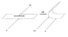
- the bending direction refers to a direction orthogonal to the folding portion (reference numeral 21) assumed in the application of the foldable display, as shown by reference numeral 22 on the polyester film (reference numeral 2) of FIG.
- the refractive index in at least one of the longitudinal direction and the width direction is 1.590 to 1.620, there is little deformation when repeatedly folded, and there is no risk of deteriorating the image quality of the foldable display, which is preferable.
- the refractive index is more preferably 1.591 to 1.600.
- the direction is preferably the above-mentioned bending direction. If it is 1.590 or more, there is no possibility that cracks will occur in the folding portion direction after the bending test described later, and of course, breakage will not occur, so that the visibility of the display can be kept good.
- the refractive index of the polyester film can be effectively adjusted by adjusting the stretching ratio and the stretching temperature. Further, a relaxation step in the stretching direction and multi-step stretching may be used to adjust the refractive index. When performing multi-stage stretching, it is preferable that the stretching ratio of the second and subsequent stages is higher than the stretching ratio of the first stage.
- the refractive index in at least one of the longitudinal direction (mechanical flow direction) and the width direction of the polyester film in the above range more preferably by controlling the refractive index in the bending direction in the above range, at the time of folding. Fatigue due to compressive stress applied to the inside of the fold can be reduced. Fatigue due to compressive stress is thought to occur mainly in the crystal part, and the smaller the number of crystals in the bending direction, the less fatigue. Therefore, it is considered that by lowering the refractive index, the amount of oriented crystals in the bending direction is reduced and compression fatigue is suppressed.
- the creep phenomenon caused by the tensile stress applied to the outside of the folding at the time of folding can be suppressed by reducing the refractive index.
- Fatigue due to tensile stress is thought to occur mainly in the amorphous part, and the molecular chains are aligned and deformed due to repeated stress. It can be inferred that the smaller the number of molecular chains aligned in the bending direction, the smaller the deformation due to alignment.
- the crystallinity that is, the density is preferable.
- the unstretched polyester sheet preferably has a draw ratio of 1.2 to 2.0 times in at least one of the longitudinal direction (mechanical flow direction) and the width direction, 1.7 to 2. 0 times is more preferable.
- the stretching direction is preferably the bending direction.
- a draw ratio of 1.2 times or more is preferable because there is no deformation in post-processing such as during hard coat coating, and a draw ratio of 2.0 times or less is preferable because uneven film thickness does not occur.
- the stretching temperature is preferably 75 to 120 ° C., more preferably 75 to 105 ° C.
- conventionally known means such as a hot air heating method, a roll heating method, and an infrared heating method can be adopted.
- the stretching temperature By setting the stretching temperature to 75 to 120 ° C., it is possible to prevent large thickness unevenness due to stretching at the above stretching ratio.
- the refractive index in the thickness direction can be reduced by stretching at a low temperature as much as possible within a range that does not cause large thickness unevenness as described above.
- the refractive index of the polyester film in the direction orthogonal to the direction in which the refractive index is 1.590 to 1.620 is preferably 1.670 to 1.700. That is, it is preferable that the refractive index in the direction orthogonal to the bending direction (direction of the folded portion) is 1.670 to 1.700.
- the refractive index in the direction orthogonal to the bending direction is 1.670 to 1.700.
- Examples of the method for adjusting the refractive index in the direction orthogonal to the bending direction include stretching ratio, stretching preheating temperature, stretching temperature, multi-stage stretching, and film relaxation.
- the draw ratio is preferably 4.0 to 6.0 times, more preferably 4.4 to 6.0 times.
- the stretching preheating temperature in the direction orthogonal to the bending direction is preferably 70 to 110 ° C.
- the film may be relaxed by 1 to 10% in either the machine flow direction (longitudinal direction) or the vertical direction (width direction).
- the refractive index in the thickness direction is preferably 1.520 or less.
- the refractive index in the thickness direction is preferably 1.520 or less.
- the refractive index in the thickness direction is preferably low, but 1.3 or more is preferable in terms of stable production, and it may be 1.4 or more. Especially preferably, it is 1.410 or more. It can be said that the above range can be achieved by increasing the stretching ratio in both the bending direction and the folding direction, but the refractive index in the thickness direction is controlled after controlling the refractive index in the bending direction and the width direction within a preferable range. In order to do so, it is preferable to set the conditions while checking the balance of each process condition in the film forming process.
- the method of controlling the refractive index in the thickness direction within the above range is as follows: stretching preheating temperature in the bending direction, stretching temperature, stretching ratio, stretching preheating temperature in the direction of the folding portion, stretching temperature, multistage stretching, high magnification stretching, or heat fixing.
- the stretching preheating temperature in the bending direction is preferably 70 ° C. to 110 ° C.
- the stretching temperature in the bending direction is preferably 75 to 120 ° C.
- the draw ratio in the bending direction is preferably 1.2 to 2.0 times, more preferably 1.7 to 2.0 times.
- the stretching preheating temperature in the folding portion direction is also preferably 75 ° C. to 110 ° C.
- the stretching temperature is preferably 75 to 120 ° C.
- the draw ratio of the folded portion is preferably 4.0 to 6.0 times, more preferably 4.4 to 6.0 times.
- the refractive index in the thickness direction can be effectively reduced while maintaining or reducing the refractive index in the bending direction.
- multi-stage stretching may be used. In that case, it is preferable to make the stretching ratio of the second stage higher than the stretching ratio of the first stage because the refractive index can be effectively controlled.
- a method of stretching again after the crystallization step may be used.
- Accelerated stretching that increases the stretching speed from the initial stage to the latter half of the stretching may be used.
- the heat fixing temperature is preferably 180 to 240 ° C.
- orientation crystallization in the stretching direction proceeds, and the refractive index in the thickness direction can be lowered.
- the reason why the impact resistance and surface hardness of the film are improved by lowering the refractive index in the thickness direction is not always clear, but the stress applied in the thickness direction due to the orientation of aromatics such as benzene rings in the molecular chain in the plane direction. It is considered to have the effect of suppressing deformation due to.
- the density of the polyester film is preferably 1.380 g / cm 3 or more. More preferably, it is 1.383 g / cm 3 or more.
- the bending direction of the polyester film corresponds to the longitudinal direction (machine flow direction). By doing so, it is easy to lower the refractive index in the bending direction at the biaxial stretching and improve the flexibility. That is, it is preferable to stretch the unstretched polyester sheet at a stretching ratio of 1.2 to 2.0 times, more preferably 1.7 to 2.0 times in the longitudinal direction to obtain a polyester film. Then, in the width direction, it can be said that it is preferable to stretch at a stretching ratio of 4.0 to 6.0 times, more preferably 4.4 to 6.0 times.
- the polyester film (1) has a refractive index of 1.590 to 1.620 in the bending direction.
- the refractive index in the direction of the folding part is 1.670 to 1.700.
- the refractive index in the thickness direction is 1.520 or less and (4) the density is 1.380 g / cm 3 or more at the same time, but it is within the above-mentioned preferable production conditions.
- the stretching ratio in the bending direction is 1.4 times or less
- the stretching ratio in the folding portion direction is less than 4.4 times
- the heat fixing temperature is 220 ° C. or less.
- the stretching ratio in the bending direction may be increased to 1.7 times or more
- the stretching ratio in the direction of the folding portion may be increased to 4.4 times or more
- the heat fixing temperature may be increased to about 230 ° C.
- the above four characteristics can be satisfied at the same time by fine-tuning any of the conditions or a combination thereof, such as lowering the stretching temperature in the bending direction and / or the folding portion direction.
- any film-forming method such as stretching, relaxation, heat fixation, and surface treatment may be used. It can be said that it is a particularly preferable aspect in the present invention to control the above in a preferable range.
- it is suitable for foldable displays, which can obtain better bending resistance and surface hardness than conventional films, especially high pencil hardness of hard coat film after laminating a hard coat layer.
- Polyester film can be provided.
- PET pellets are sufficiently vacuum-dried, then supplied to an extruder, melt-extruded into a sheet at about 280 ° C., and cooled and solidified to form an unstretched PET sheet.
- the obtained unstretched sheet is stretched 1.2 to 2.0 times, more preferably 1.7 to 2.0 times in the longitudinal direction with a roll heated to 75 to 120 ° C. to obtain a uniaxially oriented PET film. ..
- the edge of the film is gripped with a clip and guided to a hot air zone heated to 75 to 120 ° C., and after drying, 4.0 to 6.0 times in the width direction, more preferably 4.4 to 6. Stretch 0 times.
- the heat treatment zone of 180 to 240 ° C. can be guided to perform the heat treatment for 1 to 60 seconds.
- a relaxation treatment of 0 to 10% may be performed in the width direction or the longitudinal direction.
- the ultimate viscosity of the polyester film is preferably in the range of 0.50 to 1.0 dl / g.
- the ultimate viscosity is 0.50 dl / g or more, the impact resistance is improved and the internal circuit of the display is less likely to be disconnected due to an external impact, which is preferable.
- the ultimate viscosity is 1.00 dl / g or less, the film production is stable and preferable without the increase in the filter pressure of the molten fluid becoming too large.
- the easy-adhesion layer in order to improve the adhesiveness between the polyester film and the transparent conductive layer or the hard coat layer, it is also preferable to laminate the easy-adhesion layer on the polyester film.
- a coating liquid for forming the easy-adhesive layer is applied to one or both sides of an unstretched or longitudinally uniaxially stretched film, heat-treated and dried as necessary, and further unstretched in at least one direction. It can be obtained by stretching to. Heat treatment can be performed even after biaxial stretching.
- the final coating amount of the easy-adhesion layer is preferably controlled to 0.005 to 0.20 g / m 2 . When the coating amount is 0.005 g / m 2 or more, adhesiveness is obtained, which is preferable. On the other hand, when the coating amount is 0.20 g / m 2 or less, blocking resistance is obtained, which is preferable.
- the resin contained in the coating liquid used for laminating the easy-adhesion layer for example, polyester resin, polyether polyurethane resin, polyester polyurethane resin, polycarbonate polyurethane resin, acrylic resin and the like can be used without particular limitation.
- the cross-linking agent contained in the coating liquid for forming an easy-adhesion layer include melamine compounds, isocyanate compounds, oxazoline compounds, epoxy compounds, and carbodiimide compounds. It is also possible to use a mixture of two or more of each. Due to the nature of the in-line coating, these are preferably coated with an aqueous coating liquid, and the resin or cross-linking agent is preferably a water-soluble or water-dispersible resin or compound.
- the average particle size of the fine particles is preferably 2 ⁇ m or less. When the average particle size of the particles exceeds 2 ⁇ m, the particles are likely to fall off from the easy-adhesion layer.
- the particles contained in the easy-adhesion layer include titanium oxide, barium sulfate, calcium carbonate, calcium sulfate, silica, alumina, talc, kaolin, clay, calcium phosphate, mica, hectrite, zirconia, tungsten oxide, and lithium fluoride.
- examples thereof include inorganic particles such as calcium fluoride and organic polymer particles such as styrene-based, acrylic-based, melamine-based, benzoguanamine-based, and silicone-based particles. These may be added to the easy-adhesion layer alone, or may be added in combination of two or more.
- a known method can be used in the same manner as the above-mentioned coating layer.
- the reverse roll coating method, the gravure coating method, the kiss coating method, the roll brush method, the spray coating method, the air knife coating method, the wire bar coating method, the pipe doctor method, etc. can be mentioned, and these methods can be used alone. Alternatively, it can be performed in combination.
- the polyester film preferably has a hard coat layer on at least one surface thereof in order to adjust the refractive index or improve bending resistance and cracking / cutting. Since the hard coat layer exists between the polyester film and the transparent conductive layer, the adverse effect of the oligomers precipitated from the polyester film can be blocked by the hard coat layer.
- the hard coat layer is preferably used by being positioned on the polyester film or on the easy-adhesion layer.
- acrylic type, siloxane type, inorganic hybrid type, urethane acrylate type, polyester acrylate type, epoxy type and the like can be used without particular limitation. Further, two or more kinds of materials can be mixed and used, and particles such as an inorganic filler and an organic filler can be added.
- the film thickness of the hard coat layer is preferably 1 to 50 ⁇ m. When it is 1 ⁇ m or more, it is sufficiently cured and the pencil hardness becomes high, which is preferable. Further, by setting the thickness to 50 ⁇ m or less, curling due to curing shrinkage of the hard coat can be suppressed, and the handleability of the film can be improved.
- a Meyer bar, a gravure coater, a die coater, a knife coater and the like can be used without particular limitation, and can be appropriately selected depending on the viscosity and the film thickness.
- a curing method of the hard coat layer energy rays such as ultraviolet rays and electron beams and a curing method by heat can be used, and in order to reduce damage to the film, a curing method using ultraviolet rays and electron beams is preferable.
- the pencil hardness of the hard coat layer is preferably 3H or higher, and more preferably 4H or higher. If the pencil has a hardness of 3H or more, it will not be easily scratched and the visibility will not be deteriorated. Generally, it is preferable that the pencil hardness of the hard coat layer is high, but it may be 9H or less, 8H or less, or 6H or less without any problem in practical use.
- the purpose of the hard coat layer in the present invention is to adjust the refractive index or bend resistance as described above, improve cracking / cutting, improve the surface hardness, block the adverse effect of the oligomer precipitated from the polyester on the transparent conductive layer, and the like. It is preferable that the transmittance is high when it is used in a display.
- the transmittance of the hard coat film is preferably 87% or more, more preferably 88% or more. When the transmittance is 87% or more, sufficient visibility can be obtained.
- the haze of the hard coat film is generally preferably low, preferably 3% or less.
- the haze of the hard coat film is more preferably 2% or less, and most preferably 1% or less.
- the visibility of the image can be improved.
- the lower the haze the better, but from the viewpoint of stable production, 0.1% or more is preferable, and 0.3% or more may be used.
- the hard coat layer may have other functions added to it.
- functions such as an antiglare layer, an antiglare antireflection layer, an antireflection layer, a low reflection layer, and an antistatic layer having a function of adjusting a constant refractive index or improving bending resistance and cracking / cutting as described above.
- the hard coat layer to which the property is added is also preferably applied in the present invention.
- a hard coat layer can be provided on the polyester film.
- the transparent conductive layer of the touch panel module it is also preferable to provide a refractive index adjusting layer between the polyester film and the transparent conductive layer or between the hard coat layer and the transparent electrode layer in order to make the electrode pattern difficult to see.
- the hard coat layer itself may also serve as the refractive index adjusting layer, and the refractive index adjusting may be separately laminated.
- the refractive index adjusting layer examples include the above-mentioned resin layer containing the refractive index adjusting particles, a fluorine-containing resin layer, an aromatic polyimide resin, an epoxy resin, a (meth) acrylic resin (acrylate, a methacrylate compound), a polyester resin, and a urethane resin.
- the resin material include an aromatic ring, a resin having a high refractive index containing a sulfur atom or a bromine atom, and a layer such as a precursor thereof, which can be provided by coating.
- the refractive index adjusting layer ZnO, CeO 2 , Sb 2 O 3 , SnO 2 , indium tin oxide, In 2 O 3 , Al 2 O 3 , antimony-doped tin oxide, aluminum-doped zinc oxide, SiO 2 , and fluoride.
- Inorganic layers such as magnesium are also preferred, and these can be provided by a wet film forming method.
- the preferable laminated structure of the transparent conductive polyester film in the present invention is, for example, polyester film / transparent conductive layer, polyester film / easy-adhesion layer / transparent conductive layer, polyester film / hard coat layer / transparent conductive layer, polyester film / easy-adhesion.
- the transparent conductive polyester film of the present invention is used as the transparent conductive polyester film constituting the touch panel module, but it is used for all the transparent conductive polyester films constituting the touch panel module. There is no need to.
- a polyimide film, a polyamide film, a polyamideimide film, a polyester film that is not the polyester film of the present invention a polycarbonate film, an acrylic film, a triacetyl cellulose film, and a cycloolefin It can be used as a transparent base film of a transparent conductive polyester film, such as a polymer film, a polyphenylene sulfide film, and a polymethylpentene film, as appropriate.
- FIG. 1 is a schematic view for showing the bending radius when the foldable display is folded, and in consideration of the case where the polyester film is arranged on the inner surface of the folded form, FIG.
- the bending test is performed as a model assuming that the location of reference numeral 11 is set to 1.5 mm. After the bending treatment was completed, the sample was placed on a flat surface with the inside of the bending facing down, and visually observed. ⁇ : No cracks or deformation can be confirmed in the sample. ⁇ : The sample has cracks or creases, and when placed horizontally, the maximum height is 5 mm or more.
- FIG. 1 is a schematic view for showing the bending radius when the foldable display is folded, and in consideration of the case where the polyester film is arranged on the inner surface of the folded form, FIG.
- the bending test is performed as a model assuming that the location of reference numeral 11 is set to 0.5 mm.
- the film surface on the outside of the bent portion was observed at 700 times that of a digital microscope (RH8800 manufactured by HIROX), and the presence or absence of wrinkles (cracks) was observed.
- Refractive index In accordance with JIS K 7142: 2008 "Method for measuring the refractive index of plastics (Method A)", using an Abbe refractive index meter (manufactured by Atago, NAR-4T, measurement wavelength 589 nm), the longitudinal direction
- the refractive index, the refractive index in the width direction, and the refractive index in the thickness direction were determined.
- Pencil hardness Using the pencil hardness of the hard coat film as a sample, the measurement was performed at a load of 750 g and a speed of 1.0 mm / s according to JIS K 5600-5-4: 1999. In the present invention, 3H or more was regarded as acceptable.
- Total light transmittance was measured using a haze haze meter (NDH5000, manufactured by Nippon Denshoku Kogyo Co., Ltd.).
- Density The density was measured according to a method (density gradient tube method) conforming to JIS K 7112: 1999. (Unit: g / cm 3 ).
- Test force Pushing depth after unloading The sample is cut into a square of about 2 cm, and the opposite side of the measurement surface is glued (Cemedine (registered trademark) high) on the micro cover glass 18 x 18 mm (manufactured by Matsunami Glass Co., Ltd.). It was fixed at Super 30). After sticking and fixing, leave it at room temperature for 12 hours or more, and then use a dynamic ultra-micro hardness tester "DUH-211" (manufactured by Shimadzu Corporation) under the following conditions to push in depth after unloading the test force ( ⁇ m) was measured.
- a dynamic ultra-micro hardness tester "DUH-211" manufactured by Shimadzu Corporation
- Test mode Load-unload test Indenter used: Ridge angle 115 degrees, triangular pyramid indenter Indenter modulus: 1.140 ⁇ 10 6 N / mm 2 Indenter Poisson's ratio: 0.07 Test power: 50mN Load speed: 4.44 mN / sec Load holding time: 2 sec Unloading retention time: 0 sec
- Heat shrinkage rate (%) [(AB) x 100] / A
- the sample film is cut and measured separately in both the bending direction and the folding direction so that the vertical and horizontal directions are different, and the data in the direction in which the measured value is large is defined as the maximum heat shrinkage rate (%).
- esterification reaction device a continuous esterification reaction device consisting of a three-stage complete mixing tank having a stirrer, a splitter, a raw material charging port and a product extraction port is used, the TPA is 2 tons / hr, and the EG is TPA1.
- the amount of antimony trioxide is 2 mol per mol
- the amount of Sb atom is 160 ppm with respect to the produced PET, and these slurries are continuously supplied to the first esterification reaction can of the esterification reaction apparatus at normal pressure.
- the reaction was carried out at 255 ° C. with an average residence time of 4 hours.
- the reaction product in the first esterification reaction can is continuously taken out of the system and supplied to the second esterification reaction can, and distilled from the first esterification reaction can in the second esterification reaction can.
- 8% by mass of the EG to be produced is supplied to the produced polymer (produced PET), and an EG solution containing magnesium acetate in an amount of 65 ppm of Mg atoms with respect to the produced PET and 20 ppm of P atoms with respect to the produced PET.
- An EG solution containing an amount of TMPA was added, and the reaction was carried out at normal pressure at an average residence time of 1.5 hours and at 260 ° C.
- the reaction product in the second esterification reaction can is continuously taken out of the system and supplied to the third esterification reaction can, and further contains TMPA in an amount of 20 ppm of P atoms with respect to the produced PET.
- An EG solution was added, and the reaction was carried out at normal pressure at an average residence time of 0.5 hours and at 260 ° C.
- the esterification reaction product produced in the third esterification reaction can is continuously supplied to a three-stage continuous polycondensation reaction apparatus to perform polycondensation, and further, a filter medium of a stainless sintered body (nominal filtration accuracy of 5 ⁇ m). The particles were filtered through 90% of the particles) to obtain polyethylene terephthalate pellets (a) having an ultimate viscosity of 0.62 dl / g.
- reaction solution reached a predetermined amine equivalent.
- reaction solution was cooled to 40 ° C., and then 9.03 parts by mass of triethylamine was added to obtain a polyurethane prepolymer D solution.
- 450 g of water was added to a reaction vessel equipped with a homodisper capable of high-speed stirring, adjusted to 25 ° C., and while stirring and mixing at 2000 min-1, the isocyanate group-terminated prepolymer was added and water dispersed. did. Then, under reduced pressure, acetonitrile and a part of water were removed to prepare a water-soluble polyurethane resin (A) having a solid content of 35% by mass.
- Example 1 The polyethylene terephthalate pellet (a) was supplied to the extruder and melted at 285 ° C. This polymer is filtered through a stainless sintered filter medium (nominal filtration accuracy of 10 ⁇ m particles 95% cut), extruded into a sheet from the base, and then cast into a casting drum with a surface temperature of 30 ° C. using an electrostatic application casting method. They were brought into contact and cooled and solidified to form an unstretched film. This unstretched film was uniformly heated to 75 ° C. using a heating roll and heated to 85 ° C. with a non-contact heater to perform 1.4 times roll stretching (longitudinal stretching).
- the above-mentioned coating liquid for forming an easy-adhesive layer was applied to both sides of the obtained uniaxially stretched film by a roll coating method, and then dried at 80 ° C. for 20 seconds.
- the final (after biaxial stretching) coating amount after drying was adjusted to 0.06 g / m 2 . Then, it is guided to a tenter, preheated at 105 ° C., laterally stretched 4.0 times at 95 ° C., fixed in width, heat-fixed at 230 ° C. for 5 seconds, and further relaxed by 4% in the width direction at 180 ° C.
- a polyethylene terephthalate film having a thickness of 50 ⁇ m was obtained.
- Example 2 A polyester film was obtained in the same manner as in Example 1 except that the stretching ratio in the longitudinal direction shown in Table 1 was changed.
- Example 4 A polyester film was obtained in the same manner as in Example 1 except that the stretching ratio in the width direction was changed to 4.4 times and the heat fixing temperature was changed to 220 ° C.
- Example 5 A polyester film was obtained in the same manner as in Example 4 except that the stretching ratio was changed in the longitudinal direction as shown in Table 1.
- Example 7 A polyester film was obtained in the same manner as in Example 1 except that the stretching ratio in the width direction was changed to 5.5 times and the heat fixing temperature was changed to 190 ° C.
- Example 8 A polyester film was obtained in the same manner as in Example 7 except that the stretching ratio was changed in the longitudinal direction as shown in Table 1.
- Example 10 In the production process of Example 5, a polyester film was obtained in the same manner as in Example 5 except that the film was stretched in the longitudinal direction and then subjected to a relaxation heat treatment of 10% at 100 ° C.
- Example 11 In the manufacturing process of Example 5, a polyester film was obtained in the same manner as in Example 5 except that the clip was opened at 200 ° C. after heat fixing and relaxation heat treatment was performed in the longitudinal direction and the width direction. In the longitudinal direction, the tenter speed and the take-up roll speed were adjusted so that the relaxation rate was 3%. Relaxation in the width direction was left free.
- Example 12 A polyester film was obtained in the same manner as in Example 1 except that the temperature at the time of stretching in the longitudinal direction was changed to 75 ° C. and the heat fixing temperature was changed to 220 ° C.
- Example 13 The temperature at the time of stretching in the longitudinal direction was changed to 75 ° C., the stretching ratio was changed to 1.2 times, and then the stretching ratio was changed to 5.0 times in the width direction, and the stretching was performed in the same manner as in Example 1. Obtained a polyester film.
- Example 14 The stretching in the longitudinal direction of Example 3 was set to two-step stretching, the stretching ratio of the first step was set to 1.2 times, and the stretching ratio of the second step was set to 1.67 times in the same manner as in Example 3. A polyester film was obtained.
- the total stretching ratio in the longitudinal direction is about 2.0 times.
- Example 15 A polyester film was obtained in the same manner as in Example 5 except that the preheating temperature at the time of stretching in the width direction was changed to 95 ° C. and the heat fixing temperature was changed to 190 ° C.
- Example 16 The stretching in the width direction of Example 2 was set to two-step stretching, the stretching ratio of the first step was 1.5 times, the stretching ratio of the second step was 4.0 times, and the heat fixing temperature was changed to 190 ° C.
- a polyester film was obtained in the same manner as in Example 2.
- the total stretching ratio in the width direction is 6.0 times.
- Example 17 to 18 A polyester film was obtained in the same manner as in Example 2 except that the thickness was changed as shown in Table 1.
- Example 19 A polyester film was obtained in the same manner as in Example 1 except that the relaxation heat treatment in the width direction was not performed in the manufacturing process of Example 1.
- Example 20 After preparing an unstretched film in the same manner as in Example 1, the unstretched film was preheated at 75 ° C. with a tenter and laterally stretched 1.4 times at 85 ° C. The above-mentioned coating liquid for forming an easy-adhesion layer was applied to both sides of the obtained uniaxially stretched film by a roll coating method, and then dried at 80 ° C. for 20 seconds. The final (after biaxial stretching) coating amount after drying was adjusted to 0.06 g / m 2 . Uniformly heat to 105 ° C. using a heating roll and heat to 95 ° C. with a non-contact heater. Roll stretching (longitudinal stretching) was performed 4.0 times. The width was fixed and heat-fixed at 230 ° C. for 5 seconds to obtain a polyethylene terephthalate film having a thickness of 50 ⁇ m.
- Example 1 A polyester film was obtained in the same manner as in Example 1 except that the film was stretched only in the width direction without stretching in the longitudinal direction to obtain a lateral uniaxial stretching.
- Example 2 A polyester film was obtained in the same manner as in Example 7 except that the film was stretched only in the width direction without stretching in the longitudinal direction and was stretched in the lateral uniaxial direction.
- Comparative Examples 3 to 7 A polyester film was obtained in the same manner as in Example 1 except that the heat fixing temperature was changed to 220 ° C. and the PET pellets and thicknesses shown in Table 1 were used. Comparative Examples 3 to 7 are a combination of each condition level which is lower than that of Example 1 as described above and is not the best in the condition range in which the stretching ratio in the longitudinal direction and the width direction is preferable. As described in No. 1, the refractive index in the thickness direction increased, the pushing depth after unloading the test force was large, and the pencil hardness after laminating the hard coat layer was smaller than in each example.
- Example 8 A polyester film was obtained in the same manner as in Example 1 except that the stretching ratio in the longitudinal direction was changed to 2.7 times and the heat fixing temperature was changed to 220 ° C.
- Example 9 A polyester film was obtained in the same manner as in Example 1 except that the stretching ratio in the longitudinal direction was changed to 3.4 times.
- Example 12 A polyester film was obtained in the same manner as in Example 1 except that the preheating temperature in the width direction was changed to 120 ° C.
- a hard coat coating liquid a is applied to one surface of the above-mentioned film so that the film thickness after drying is 5 ⁇ m, dried at 80 ° C. for 1 minute, and then irradiated with ultraviolet rays. (Integrated light amount 200 mJ / cm 2 ), a hard coat film was obtained. Then, using a Meyer bar, a metal nanowire-containing coating liquid was applied to the surface of the prepared hard coat layer so that the film thickness after drying was 5 ⁇ m, dried at 80 ° C. for 10 minutes, and then transparent conductivity. A polyester film was obtained. The evaluation results are shown in Table 1.
- Example 21 In the same manner as in Example 1, a polyethylene terephthalate film having a thickness of 50 ⁇ m was obtained, and then a hard coat film coated with the hard coat coating liquid b was obtained, and then the hard coat coating liquid a was changed to the hard coat coating liquid b. In the same way, a hard coat film was obtained.
- a touch panel module using the transparent conductive polyester film was incorporated into an organic EL display to create a smartphone-type foldable display that can be folded in half at the center of the whole where the radius corresponding to the bending radius in FIG. 1 is 3 mm.
- the one using the transparent conductive polyester film of each example was one that satisfied the operation and visibility as a smartphone that could be folded in half at the center and carried.
- the surface was not dented by an external force.
- the foldable display using the transparent conductive polyester film of each comparative example seems to have caused image distortion in the foldable portion of the display as the frequency of use increases, which is not very preferable. In addition, some dents were confirmed on the surface.
- the foldable display using the transparent conductive polyester film for the foldable display of the present invention maintains mass productivity and does not cause image distortion at the foldable portion of the display.
- a mobile terminal device or an image display device equipped with a foldable display using the transparent conductive polyester film of the present invention for a touch panel module provides a beautiful image, is rich in functionality, and is excellent in convenience such as portability. It is a thing.
- Folding display 11 Bending radius 2: Transparent conductive polyester film of the folding display 21: Folding part 22: Bending direction (direction orthogonal to the folding part)
Landscapes
- Chemical & Material Sciences (AREA)
- Engineering & Computer Science (AREA)
- Theoretical Computer Science (AREA)
- Chemical Kinetics & Catalysis (AREA)
- Organic Chemistry (AREA)
- Polymers & Plastics (AREA)
- Medicinal Chemistry (AREA)
- Health & Medical Sciences (AREA)
- General Physics & Mathematics (AREA)
- Physics & Mathematics (AREA)
- General Engineering & Computer Science (AREA)
- Human Computer Interaction (AREA)
- Manufacturing & Machinery (AREA)
- Materials Engineering (AREA)
- Laminated Bodies (AREA)
- Devices For Indicating Variable Information By Combining Individual Elements (AREA)
- Non-Insulated Conductors (AREA)
- Manufacture Of Macromolecular Shaped Articles (AREA)
- Coating Of Shaped Articles Made Of Macromolecular Substances (AREA)
Priority Applications (7)
| Application Number | Priority Date | Filing Date | Title |
|---|---|---|---|
| CN202080038854.2A CN113874211B (zh) | 2019-05-28 | 2020-05-14 | 透明导电性聚酯薄膜及其用途 |
| JP2020533167A JP7435449B2 (ja) | 2019-05-28 | 2020-05-14 | 透明導電性ポリエステルフィルムとその用途 |
| KR1020217042276A KR20220013564A (ko) | 2019-05-28 | 2020-05-14 | 투명 도전성 폴리에스테르 필름과 그 용도 |
| US17/614,260 US12354504B2 (en) | 2019-05-28 | 2020-05-14 | Transparent conductive polyester film and use of same |
| EP20815504.4A EP3978243A4 (en) | 2019-05-28 | 2020-05-14 | TRANSPARENT CONDUCTIVE POLYESTER FILM AND ITS USE |
| JP2024005507A JP7742032B2 (ja) | 2019-05-28 | 2024-01-17 | 透明導電性ポリエステルフィルムとその用途 |
| JP2025136196A JP2025168368A (ja) | 2019-05-28 | 2025-08-19 | 透明導電性ポリエステルフィルムとその用途 |
Applications Claiming Priority (2)
| Application Number | Priority Date | Filing Date | Title |
|---|---|---|---|
| JP2019-099161 | 2019-05-28 | ||
| JP2019099161 | 2019-05-28 |
Publications (1)
| Publication Number | Publication Date |
|---|---|
| WO2020241281A1 true WO2020241281A1 (ja) | 2020-12-03 |
Family
ID=73553430
Family Applications (1)
| Application Number | Title | Priority Date | Filing Date |
|---|---|---|---|
| PCT/JP2020/019267 Ceased WO2020241281A1 (ja) | 2019-05-28 | 2020-05-14 | 透明導電性ポリエステルフィルムとその用途 |
Country Status (7)
| Country | Link |
|---|---|
| US (1) | US12354504B2 (https=) |
| EP (1) | EP3978243A4 (https=) |
| JP (3) | JP7435449B2 (https=) |
| KR (1) | KR20220013564A (https=) |
| CN (1) | CN113874211B (https=) |
| TW (1) | TWI884958B (https=) |
| WO (1) | WO2020241281A1 (https=) |
Cited By (10)
| Publication number | Priority date | Publication date | Assignee | Title |
|---|---|---|---|---|
| JPWO2020241312A1 (https=) * | 2019-05-30 | 2020-12-03 | ||
| CN113193154A (zh) * | 2021-04-30 | 2021-07-30 | 合肥维信诺科技有限公司 | 柔性显示面板及其制备方法、显示装置 |
| US11899167B2 (en) | 2019-05-28 | 2024-02-13 | Toyobo Co., Ltd. | Polyester film, laminated film, and use thereof |
| US11926720B2 (en) | 2019-05-28 | 2024-03-12 | Toyobo Co., Ltd. | Polyester film and application therefor |
| US11934226B2 (en) | 2019-02-08 | 2024-03-19 | Toyobo Co., Ltd. | Foldable display and portable terminal device |
| US11939499B2 (en) | 2019-05-28 | 2024-03-26 | Toyobo Co., Ltd. | Multilayer film and use of same |
| US11997916B2 (en) | 2019-02-08 | 2024-05-28 | Toyobo Co., Ltd. | Polyester film and use thereof |
| US12298547B2 (en) | 2019-05-30 | 2025-05-13 | Toyobo Co., Ltd. | Foldable display |
| US12319801B2 (en) | 2019-07-12 | 2025-06-03 | Toyobo Co., Ltd. | Hard coating film for foldable display, and application of said film |
| US12351730B2 (en) | 2019-07-12 | 2025-07-08 | Toyobo Co., Ltd. | Hard coat film for foldable display and use thereof |
Families Citing this family (6)
| Publication number | Priority date | Publication date | Assignee | Title |
|---|---|---|---|---|
| KR20230023108A (ko) * | 2021-08-09 | 2023-02-17 | 삼성디스플레이 주식회사 | 표시 장치 |
| WO2023107590A1 (en) * | 2021-12-07 | 2023-06-15 | Intevac, Inc. | System and method for scratch and scuff resistant low reflectivity optical coatings |
| KR102822299B1 (ko) * | 2022-09-28 | 2025-06-19 | 코오롱인더스트리 주식회사 | Creep변형 거동이 개선된 광학필름 |
| US20260026239A1 (en) * | 2022-09-28 | 2026-01-22 | Kolon Industries, Inc. | Optical film having improved creep deformation behavior |
| KR20250014034A (ko) * | 2023-07-18 | 2025-02-03 | 삼성디스플레이 주식회사 | 전자 장치 |
| KR20250121176A (ko) * | 2024-02-02 | 2025-08-12 | 삼성디스플레이 주식회사 | 윈도우 및 이를 포함하는 전자 장치 |
Citations (6)
| Publication number | Priority date | Publication date | Assignee | Title |
|---|---|---|---|---|
| JPS619619A (ja) * | 1984-06-25 | 1986-01-17 | Toray Ind Inc | 液晶表示素子用−軸配向ポリエチレンテレフタレ−トフイルム |
| WO2013100042A1 (ja) * | 2011-12-28 | 2013-07-04 | 東洋紡株式会社 | 液晶表示装置 |
| JP2014065887A (ja) * | 2012-09-10 | 2014-04-17 | Toyobo Co Ltd | 光学用易接着性ポリエステルフィルム |
| JP2018072663A (ja) * | 2016-11-01 | 2018-05-10 | 東洋紡株式会社 | 折りたたみ型ディスプレイ及び携帯端末機器 |
| WO2018150940A1 (ja) * | 2017-02-20 | 2018-08-23 | 東洋紡株式会社 | ポリエステルフィルムとその用途 |
| WO2018159285A1 (ja) * | 2017-03-02 | 2018-09-07 | 東洋紡株式会社 | 折りたたみ型ディスプレイの表面保護フィルム用ポリエステルフィルムとその用途 |
Family Cites Families (164)
| Publication number | Priority date | Publication date | Assignee | Title |
|---|---|---|---|---|
| US4115617A (en) | 1976-03-24 | 1978-09-19 | Teijin Limited | Weather-resistant adhesive film |
| JPS56104984A (en) | 1980-01-24 | 1981-08-21 | Nippon Kanko Shikiso Kenkyusho:Kk | Bichromic pigment for yellow liquid crystal |
| JPS5995513A (ja) * | 1982-11-25 | 1984-06-01 | Toray Ind Inc | 液晶表示セル |
| JPS6097323A (ja) | 1983-11-01 | 1985-05-31 | Toray Ind Inc | 液晶表示用ポリエステルフイルムおよびその製造方法 |
| JPS60203422A (ja) * | 1984-03-28 | 1985-10-15 | Teijin Ltd | 2軸配向ポリエステルフィルム |
| JPS60228568A (ja) | 1984-04-26 | 1985-11-13 | Casio Comput Co Ltd | 液晶用二色性染料 |
| JPS63301850A (ja) | 1988-01-13 | 1988-12-08 | Nippon Kanko Shikiso Kenkyusho:Kk | アゾ化合物からなる液晶用二色性色素 |
| CA2094434A1 (en) | 1992-04-30 | 1993-10-31 | Tomoyuki Kotani | Biaxially oriented laminated polyester film for magnetic recording media |
| DE4408171A1 (de) | 1994-03-11 | 1995-09-14 | Basf Ag | Neue polymerisierbare flüssigkristalline Verbindungen |
| JPH10316783A (ja) | 1998-05-13 | 1998-12-02 | Toyobo Co Ltd | フィルム |
| JP2000063538A (ja) | 1998-08-19 | 2000-02-29 | Teijin Ltd | ポリエステルフィルム及びその製造方法 |
| EP0985701B1 (en) | 1998-09-11 | 2007-07-11 | Toray Industries, Inc. | Biaxially oriented polyester film and a process for its production |
| JP2000177001A (ja) | 1998-10-05 | 2000-06-27 | Toray Ind Inc | 成形用二軸延伸ポリエステルフィルム |
| ATE278731T1 (de) | 2000-01-24 | 2004-10-15 | Rolic Ag | Photoaktive polyimide, polyamidsäuren oder -ester mit seitenständigen, photovernetzbaren gruppen |
| DE10016524A1 (de) | 2000-04-03 | 2001-10-04 | Basf Ag | Polymerisierbare Flüssigkristalle |
| JP2001324603A (ja) | 2000-05-15 | 2001-11-22 | Toyobo Co Ltd | ブラウン管反射防止用二軸配向ポリエステルフィルム |
| JP2001350021A (ja) | 2000-06-06 | 2001-12-21 | Sumitomo Chem Co Ltd | 薄型光学積層体及びその製造方法 |
| EP1293532B1 (en) | 2000-06-15 | 2007-05-09 | Teijin Limited | Biaxially oriented polyester film for light diffuser plate and light diffuser plate |
| US6733958B2 (en) | 2000-08-30 | 2004-05-11 | Dainippon Ink And Chemicals, Inc. | Material for photo-alignment layer, photo-alignment layer and method of manufacturing the same |
| JP4900632B2 (ja) | 2000-08-30 | 2012-03-21 | Dic株式会社 | 光配向膜用材料、光配向膜及びその製造方法 |
| US6761968B2 (en) | 2000-12-01 | 2004-07-13 | Teijin Limited | Biaxially oriented polyester film |
| JP2002178400A (ja) | 2000-12-18 | 2002-06-26 | Teijin Ltd | 二軸配向ポリエステルフィルム |
| JP4534107B2 (ja) | 2001-01-30 | 2010-09-01 | Dic株式会社 | 光配向材料及びこれを用いた光配向膜の製造方法 |
| EP1229066A1 (en) | 2001-02-05 | 2002-08-07 | Rolic AG | Photoactive polymer |
| JP4803412B2 (ja) | 2001-03-14 | 2011-10-26 | Dic株式会社 | マレイミド誘導体を含有する光配向材料及び光配向膜の製造方法 |
| JP2002303722A (ja) | 2001-04-04 | 2002-10-18 | Fuji Photo Film Co Ltd | 光学補償シート |
| JP4058481B2 (ja) | 2001-04-12 | 2008-03-12 | 日東電工株式会社 | 重合性液晶化合物および光学フィルム |
| JP3840937B2 (ja) | 2001-09-17 | 2006-11-01 | 東洋紡績株式会社 | 一軸配向ポリエステルフィルム、並びにこれを用いた表面保護フィルムおよび離型フィルム |
| JP2003114325A (ja) | 2001-10-03 | 2003-04-18 | Nitto Denko Corp | 積層1/4波長板、円偏光板及びこれを用いた液晶表示装置、ならびにその製造方法 |
| CN100422773C (zh) * | 2002-02-19 | 2008-10-01 | 日东电工株式会社 | 包含至少两层光学各向异性层的层压延迟片的制造方法 |
| KR100752092B1 (ko) | 2002-02-19 | 2007-08-28 | 닛토덴코 가부시키가이샤 | 적층위상차판, 이를 사용한 적층편광판 및 화상표시장치 |
| JP2004136644A (ja) | 2002-08-20 | 2004-05-13 | Konica Minolta Holdings Inc | インクジェット記録用紙 |
| JP4507490B2 (ja) | 2002-12-26 | 2010-07-21 | チッソ株式会社 | 光重合性液晶組成物および液晶フィルム |
| JP2004299101A (ja) | 2003-03-28 | 2004-10-28 | Toray Ind Inc | 表面保護用透明積層フィルム |
| TWI295303B (en) | 2003-08-21 | 2008-04-01 | Toyo Boseki | Optical-use adhesive polyester film and optical-use laminatede film |
| JP4341904B2 (ja) | 2003-09-12 | 2009-10-14 | 日東電工株式会社 | 異方性フィルムの製造方法 |
| WO2005045485A1 (en) | 2003-11-06 | 2005-05-19 | Koninklijke Philips Electronics N.V. | Dichroic guest-host polarizer comprising an oriented polymer film |
| JP5031177B2 (ja) | 2003-11-26 | 2012-09-19 | 三菱樹脂株式会社 | 蒸着用ポリエステルフィルム |
| JP4721721B2 (ja) | 2004-02-18 | 2011-07-13 | 株式会社Adeka | 重合性化合物及び該化合物を含有する重合性液晶組成物 |
| JP2005331909A (ja) | 2004-04-22 | 2005-12-02 | Fuji Photo Film Co Ltd | 偏光板および液晶表示装置 |
| JP2006113203A (ja) | 2004-10-13 | 2006-04-27 | Nitto Denko Corp | 積層光学フィルム、楕円偏光板および画像表示装置 |
| JP4888690B2 (ja) | 2004-12-27 | 2012-02-29 | Dic株式会社 | 光配向膜の製造方法 |
| JP4687952B2 (ja) | 2004-12-28 | 2011-05-25 | 東洋紡績株式会社 | 光学用積層ポリエステルフィルム及びその製造方法 |
| GB0505517D0 (en) | 2005-03-17 | 2005-04-27 | Dupont Teijin Films Us Ltd | Coated polymeric substrates |
| US20090068472A1 (en) | 2005-03-23 | 2009-03-12 | Nitto Denko Corporation | Method of producing an optical film, and image display apparatus using the optical film obtained by the production method |
| JP5200325B2 (ja) | 2005-04-04 | 2013-06-05 | 三菱化学株式会社 | 湿式成膜法により形成された異方性色素膜及び偏光素子 |
| JP4946151B2 (ja) | 2005-06-10 | 2012-06-06 | Jnc株式会社 | 重合性液晶組成物 |
| TW200712579A (en) | 2005-08-12 | 2007-04-01 | Dainippon Printing Co Ltd | Protective film for polarizing plate and polarizing plate |
| JP2007076839A (ja) | 2005-09-15 | 2007-03-29 | Fuji Xerox Co Ltd | 画像形成装置 |
| JP4661502B2 (ja) | 2005-09-29 | 2011-03-30 | Dic株式会社 | 光配向膜用組成物および光配向膜の製造方法 |
| JP5145660B2 (ja) | 2005-10-18 | 2013-02-20 | Dic株式会社 | 光配向膜用組成物、光配向膜の製造方法、及びこれを用いた光学異方体、光学素子、その製造方法 |
| JP5186734B2 (ja) | 2005-10-18 | 2013-04-24 | Dic株式会社 | アゾ化合物、光配向膜用組成物、光配向膜及び液晶表示素子 |
| JP4816003B2 (ja) | 2005-10-28 | 2011-11-16 | Dic株式会社 | 光配向膜用組成物、光配向膜の製造方法、及びこれを用いた光学異方体、光学素子、その製造方法 |
| JP2007119415A (ja) | 2005-10-31 | 2007-05-17 | Adeka Corp | 縮合環を有する重合性液晶化合物並びに該重合性液晶化合物の単独重合物及び共重合物 |
| JP2007133184A (ja) | 2005-11-10 | 2007-05-31 | Nippon Kayaku Co Ltd | 新規偏光素子用光配向膜 |
| JP4935982B2 (ja) | 2005-11-10 | 2012-05-23 | Dic株式会社 | 光配向膜用組成物、光学異方体及びその製造方法 |
| TWI406061B (zh) | 2005-11-10 | 2013-08-21 | Dainippon Ink & Chemicals | 光配向膜用組成物、光學異向體及其製法 |
| JP4545095B2 (ja) | 2006-01-11 | 2010-09-15 | 株式会社Adeka | 新規重合性化合物 |
| JP4919403B2 (ja) * | 2006-09-14 | 2012-04-18 | 日本化薬株式会社 | 高耐久性偏光板 |
| JP2008070708A (ja) | 2006-09-15 | 2008-03-27 | Bridgestone Corp | 反射防止・近赤外線遮断フィルタ、これを用いたプラズマディスプレイパネル用光学フィルタ及びプラズマディスプレイパネル |
| JP2008149577A (ja) | 2006-12-18 | 2008-07-03 | Kaneka Corp | シート、積層体、偏光板、液晶表示装置、更にはその製造方法 |
| JP2008242231A (ja) | 2007-03-28 | 2008-10-09 | Mitsui Chemicals Inc | 視野角制御フィルムおよびそれを用いたディスプレイ用光学フィルター |
| JP2009093074A (ja) | 2007-10-11 | 2009-04-30 | Nitto Denko Corp | 偏光板の製造方法、偏光板、光学フィルムおよび画像表示装置 |
| JP5076810B2 (ja) | 2007-10-31 | 2012-11-21 | Dic株式会社 | 光配向膜用組成物、光配向膜、及び光学異方体 |
| JP5257023B2 (ja) | 2007-11-29 | 2013-08-07 | 東洋紡株式会社 | ポリエチレンテレフタレート系樹脂フィルム、およびその製造方法 |
| JP5678429B2 (ja) | 2008-12-25 | 2015-03-04 | 三菱化学株式会社 | 異方性膜用アゾ化合物、該化合物を含有する組成物、異方性膜及び偏光素子 |
| WO2010100917A1 (ja) | 2009-03-05 | 2010-09-10 | 日東電工株式会社 | 薄型高機能偏光膜およびその製造方法 |
| JP4853976B2 (ja) | 2009-03-26 | 2012-01-11 | 日東電工株式会社 | 異方性フィルムの製造方法 |
| JP5594860B2 (ja) | 2009-03-27 | 2014-09-24 | リンテック株式会社 | ハードコートフィルムの加工方法、ハードコートフィルムおよび保護フィルム |
| JP5244848B2 (ja) | 2009-05-01 | 2013-07-24 | 日東電工株式会社 | 偏光子の製造方法 |
| US20160025910A1 (en) | 2009-05-01 | 2016-01-28 | Nitto Denko Corporation | Method for producing polarizer |
| JP5644064B2 (ja) | 2009-06-09 | 2014-12-24 | 住友化学株式会社 | 液晶表示装置及びそれに用いる偏光板 |
| CN102473480B (zh) * | 2009-07-08 | 2014-10-08 | 日东电工株式会社 | 透明导电性膜、电子设备及触摸面板 |
| JP4888853B2 (ja) | 2009-11-12 | 2012-02-29 | 学校法人慶應義塾 | 液晶表示装置の視認性改善方法、及びそれを用いた液晶表示装置 |
| JP2011154134A (ja) | 2010-01-26 | 2011-08-11 | Panasonic Electric Works Co Ltd | ハードコートフィルム |
| JP5502023B2 (ja) | 2010-09-03 | 2014-05-28 | 日東電工株式会社 | 偏光膜を有する光学フィルム積層体ロールの製造方法 |
| JP4691205B1 (ja) | 2010-09-03 | 2011-06-01 | 日東電工株式会社 | 薄型高機能偏光膜を含む光学フィルム積層体の製造方法 |
| JP5511730B2 (ja) | 2010-09-03 | 2014-06-04 | 日東電工株式会社 | 光学的パネル組立体の連続的製造方法及び装置 |
| JP5478553B2 (ja) | 2010-09-03 | 2014-04-23 | 日東電工株式会社 | 連続ウェブ状光学フィルム積層体ロール及びその製造方法 |
| JP5361941B2 (ja) | 2010-09-03 | 2013-12-04 | 日東電工株式会社 | 偏光膜を有する積層体ストリップロールの製造方法 |
| JP5701679B2 (ja) | 2010-09-03 | 2015-04-15 | 日東電工株式会社 | 矩形形状のパネルに偏光膜を有する光学フィルムを順次的に貼り付ける方法及び装置 |
| JP5474869B2 (ja) | 2010-09-03 | 2014-04-16 | 日東電工株式会社 | 偏光膜を有する積層体ストリップロールの製造方法 |
| JP2012107080A (ja) | 2010-11-15 | 2012-06-07 | Toray Ind Inc | 二軸配向ポリエステルフィルム |
| JP5692225B2 (ja) | 2011-03-09 | 2015-04-01 | 東洋紡株式会社 | 易接着性ポリエステルフィルム |
| JP5770665B2 (ja) | 2011-03-28 | 2015-08-26 | 富士フイルム株式会社 | ポリエステルフィルム、ガスバリアフィルム、太陽電池用バックシート、有機デバイス、並びに、太陽電池モジュール |
| KR101833582B1 (ko) | 2011-05-18 | 2018-02-28 | 도요보 가부시키가이샤 | 3차원 화상표시 대응 액정표시장치에 적합한 편광판 및 액정표시장치 |
| TW201311743A (zh) | 2011-07-07 | 2013-03-16 | Sumitomo Chemical Co | 光反應性液晶配向劑、與液晶配向元件及其製造方法 |
| JP5691947B2 (ja) | 2011-09-02 | 2015-04-01 | コニカミノルタ株式会社 | ガスバリア性フィルム及びガスバリア性フィルムの製造方法 |
| US8960943B2 (en) | 2011-10-05 | 2015-02-24 | Jessica Wang | Lighted display having portions printed with a coating containing light bending particles |
| TWI564598B (zh) | 2011-10-12 | 2017-01-01 | Sumitomo Chemical Co | A polarizing film, a circularly polarizing plate, and the like |
| JP2013114131A (ja) | 2011-11-30 | 2013-06-10 | Dainippon Printing Co Ltd | 位相差層形成用の重合性液晶組成物、パターン位相差フィルム及びパターン位相差フィルムの製造方法 |
| JP6182858B2 (ja) | 2011-12-28 | 2017-08-23 | 東洋紡株式会社 | 液晶表示装置、偏光板および偏光子保護フィルム |
| JP5397824B1 (ja) * | 2012-01-31 | 2014-01-22 | 東レフィルム加工株式会社 | 透明導電性フィルム、タッチパネルおよび表示装置 |
| KR102129135B1 (ko) | 2012-02-28 | 2020-07-01 | 스미또모 가가꾸 가부시키가이샤 | 편광막, 원편광판 및 이들의 제조 방법 |
| JP5908752B2 (ja) | 2012-03-09 | 2016-04-26 | 帝人デュポンフィルム株式会社 | 透明導電性フィルム基材用積層体 |
| CN104159735B (zh) * | 2012-03-09 | 2017-03-22 | 帝人杜邦薄膜日本有限公司 | 透明导电性薄膜基材用层压体 |
| JP2014170221A (ja) | 2013-02-07 | 2014-09-18 | Nitto Denko Corp | 円偏光板および屈曲可能な表示装置 |
| JP2014186210A (ja) | 2013-03-25 | 2014-10-02 | Toppan Printing Co Ltd | ハードコートフィルム |
| JP2014206682A (ja) | 2013-04-15 | 2014-10-30 | 三菱化学株式会社 | In−Cell型偏光子のオーバーコート層形成用樹脂組成物、In−Cell型積層偏光子及びこれを備えてなる液晶表示素子 |
| WO2014203894A1 (ja) | 2013-06-19 | 2014-12-24 | 富士フイルム株式会社 | ポリエステルフィルム、偏光板及び画像表示装置 |
| JP6502006B2 (ja) | 2013-06-25 | 2019-04-17 | 日産化学株式会社 | 横電界駆動型液晶表示素子用液晶配向膜を有する基板の製造方法 |
| JP2015030157A (ja) | 2013-08-01 | 2015-02-16 | 凸版印刷株式会社 | 透明導電性積層体の製造方法 |
| JP5768853B2 (ja) | 2013-09-24 | 2015-08-26 | 大日本印刷株式会社 | 位相差フィルム |
| JP2015129210A (ja) | 2014-01-06 | 2015-07-16 | 大阪有機化学工業株式会社 | ブロックカルボン酸型光配向材料 |
| JP6086884B2 (ja) | 2014-01-28 | 2017-03-01 | 富士フイルム株式会社 | 重合性化合物、ポリマー、重合性組成物、フィルム、および投映像表示用ハーフミラー |
| JP2015174357A (ja) | 2014-03-17 | 2015-10-05 | 三菱樹脂株式会社 | 積層ポリエステルフィルム |
| JP6297379B2 (ja) | 2014-03-26 | 2018-03-20 | 富士フイルム株式会社 | ポリエステル樹脂フィルム、ポリエステル樹脂フィルムの製造方法、偏光板、画像表示装置、ハードコートフィルム、タッチパネル用センサーフィルム、ガラス飛散防止フィルム、およびタッチパネル |
| JP2015232120A (ja) | 2014-05-16 | 2015-12-24 | 東レ株式会社 | 光学用ポリエステルフィルム及びそれを用いた偏光板および透明導電性フィルム |
| JP6246078B2 (ja) | 2014-06-13 | 2017-12-13 | 富士フイルム株式会社 | 偏光膜の製造方法およびその応用 |
| CN106488839B (zh) | 2014-07-18 | 2019-11-12 | 富士胶片株式会社 | 单轴取向聚酯薄膜、硬涂层薄膜、触摸面板用传感器薄膜、防飞散膜、防反射膜、触摸面板及单轴取向聚酯薄膜的制造方法 |
| EP3176614A4 (en) | 2014-07-30 | 2018-04-25 | Konica Minolta, Inc. | Optical film and method for manufacturing optical film |
| KR102256084B1 (ko) | 2014-08-04 | 2021-05-25 | 엘지디스플레이 주식회사 | 플렉서블 표시장치 및 이의 제조방법 |
| JP5880642B2 (ja) | 2014-08-06 | 2016-03-09 | 東洋紡株式会社 | 光学用積層ポリエステルフィルム |
| KR101659161B1 (ko) | 2014-09-03 | 2016-09-23 | 삼성에스디아이 주식회사 | 편광판 및 이를 포함하는 액정표시장치 |
| JP2016075869A (ja) | 2014-10-09 | 2016-05-12 | エルジー ディスプレイ カンパニー リミテッド | フレキシブル表示装置 |
| JP2016090925A (ja) | 2014-11-10 | 2016-05-23 | コニカミノルタ株式会社 | 光学フィルム、タッチパネル用センサー及び光学フィルムの製造方法 |
| KR20160103682A (ko) | 2015-02-25 | 2016-09-02 | 동우 화인켐 주식회사 | 폴더블 하드코팅 필름의 제조방법 |
| TWI702415B (zh) | 2015-07-17 | 2020-08-21 | 日商大日本印刷股份有限公司 | 光學構件用積層體及影像顯示裝置 |
| JP7016604B2 (ja) | 2015-07-17 | 2022-02-07 | 大日本印刷株式会社 | タッチパネル用積層体、折り畳み式画像表示装置 |
| JP6578780B2 (ja) | 2015-07-17 | 2019-09-25 | 大日本印刷株式会社 | タッチパネル用積層体、及び、折り畳み式画像表示装置 |
| JP2017067819A (ja) | 2015-09-28 | 2017-04-06 | 東レ株式会社 | 光学用ポリエステルフィルム及びそれを用いた偏光板、透明導電性フィルム |
| KR101893741B1 (ko) | 2015-11-13 | 2018-08-30 | 도요보 가부시키가이샤 | 적층 폴리에스테르 필름 |
| JP7254514B6 (ja) | 2015-11-27 | 2023-04-21 | エスケイシー・カンパニー・リミテッド | 偏光子用保護フィルム、偏光板、およびそれらを含む表示装置 |
| KR102655116B1 (ko) | 2015-12-08 | 2024-04-08 | 도레이 카부시키가이샤 | 적층 필름 |
| CN108472928B (zh) | 2015-12-28 | 2020-05-12 | 东洋纺株式会社 | 层叠聚酯膜 |
| KR101951864B1 (ko) | 2016-03-14 | 2019-02-25 | 주식회사 엘지화학 | 반사 방지 필름 및 디스플레이 장치 |
| WO2017200042A1 (ja) | 2016-05-20 | 2017-11-23 | 大日本印刷株式会社 | 光学積層体、及び、画像表示装置 |
| US10668690B2 (en) | 2016-07-01 | 2020-06-02 | Dai Nippon Printing Co., Ltd. | Optical layered body and display device |
| JP2018010086A (ja) | 2016-07-12 | 2018-01-18 | 富士フイルム株式会社 | 転写フィルムの製造方法、転写フィルム、転写フィルムロール、及び、硬化性樹脂組成物 |
| JP2018022060A (ja) | 2016-08-04 | 2018-02-08 | 東洋紡株式会社 | 長尺偏光フィルム及び液晶表示装置、エレクトレットルミネッセンス表示装置 |
| JP6932420B2 (ja) | 2016-08-15 | 2021-09-08 | 日東電工株式会社 | フレキシブル画像表示装置用粘着剤組成物、フレキシブル画像表示装置用粘着剤層、フレキシブル画像表示装置用積層体、及び、フレキシブル画像表示装置 |
| CN109073788B (zh) | 2016-08-23 | 2023-09-01 | 琳得科株式会社 | 硬涂膜 |
| KR20180034056A (ko) | 2016-09-27 | 2018-04-04 | 삼성전자주식회사 | 표시 장치용 윈도우 및 표시 장치 |
| KR102675570B1 (ko) | 2016-09-30 | 2024-06-13 | 삼성디스플레이 주식회사 | 편광 유닛 및 이를 포함하는 표시 장치 |
| JP7021887B2 (ja) | 2016-09-30 | 2022-02-17 | 住友化学株式会社 | 光学フィルムの製造方法 |
| KR102494640B1 (ko) | 2016-10-05 | 2023-02-06 | 미쯔비시 케미컬 주식회사 | 적층 폴리에스테르 필름 |
| KR102226092B1 (ko) | 2016-10-12 | 2021-03-09 | 코니카 미놀타 가부시키가이샤 | 편광판 및 액정 표시 장치 |
| JP6957885B2 (ja) | 2017-01-31 | 2021-11-02 | 東レ株式会社 | 有機エレクトロルミネッセンス表示装置用フィルムおよび積層シート |
| US10303218B2 (en) | 2017-02-01 | 2019-05-28 | Apple Inc. | Foldable cover and display for an electronic device |
| KR102303171B1 (ko) | 2017-03-31 | 2021-09-16 | 도요보 가부시키가이샤 | 편광자 보호 필름, 편광판 및 화상 표시 장치 |
| JP7013680B2 (ja) | 2017-06-01 | 2022-02-01 | 大日本印刷株式会社 | ハードコートフィルム、電離放射線硬化性樹脂組成物、及びディスプレイ |
| US20180368255A1 (en) * | 2017-06-14 | 2018-12-20 | Eastman Chemical Company | Extruded stretchable substrates for flexible printed circuits and methods of making |
| US10070516B1 (en) * | 2017-06-14 | 2018-09-04 | Eastman Chemical Company | Multilayer stretchable films for flexible printed circuits and methods of making |
| JP7187764B2 (ja) | 2017-06-21 | 2022-12-13 | 東洋紡株式会社 | 液晶表示装置 |
| JP7436205B2 (ja) | 2017-07-31 | 2024-02-21 | 日東電工株式会社 | フレキシブル画像表示装置用積層体、及び、フレキシブル画像表示装置 |
| JP2019082648A (ja) | 2017-10-31 | 2019-05-30 | Jnc株式会社 | 粘着層付ハードコートフィルム、画像表示装置 |
| JP2019152686A (ja) * | 2018-02-28 | 2019-09-12 | 大日本印刷株式会社 | 機能性フィルム、偏光板、および画像表示装置 |
| CN111989357B (zh) | 2018-04-19 | 2023-08-11 | 东洋纺株式会社 | 折叠型显示器的表面保护膜用聚酯薄膜及其用途 |
| US12066864B2 (en) | 2018-05-07 | 2024-08-20 | Toyobo Co., Ltd. | Folding-type display and portable terminal device |
| KR102403282B1 (ko) | 2018-11-06 | 2022-05-27 | 삼성에스디아이 주식회사 | 발광표시장치용 편광판 및 이를 포함하는 발광표시장치 |
| EP3922668A4 (en) | 2019-02-08 | 2022-11-23 | Toyobo Co., Ltd. | POLYESTER FILM AND USE THEREOF |
| JP7502722B2 (ja) | 2019-02-08 | 2024-06-19 | 東洋紡株式会社 | 折りたたみ型ディスプレイ及び携帯端末機器 |
| JP7334047B2 (ja) | 2019-03-13 | 2023-08-28 | 日東電工株式会社 | 画像表示装置および該画像表示装置に用いられる円偏光板 |
| KR102308471B1 (ko) * | 2019-05-08 | 2021-10-05 | 에스케이씨 주식회사 | 폴리에스테르 필름 및 이를 포함하는 플렉서블 디스플레이 장치 |
| EP3978554A4 (en) | 2019-05-28 | 2023-06-21 | Toyobo Co., Ltd. | POLYESTER FILM, LAMINATED FILM AND USE THEREOF |
| WO2020241280A1 (ja) | 2019-05-28 | 2020-12-03 | 東洋紡株式会社 | ポリエステルフィルムとその用途 |
| JP7435448B2 (ja) | 2019-05-28 | 2024-02-21 | 東洋紡株式会社 | 積層フィルムとその用途 |
| KR102905588B1 (ko) | 2019-05-30 | 2025-12-30 | 도요보 가부시키가이샤 | 폴딩형 디스플레이용 편광판 |
| WO2020241732A1 (ja) * | 2019-05-30 | 2020-12-03 | 大日本印刷株式会社 | 光学用のプラスチックフィルム、偏光板及び画像表示装置 |
| US12298547B2 (en) * | 2019-05-30 | 2025-05-13 | Toyobo Co., Ltd. | Foldable display |
| EP3998161A4 (en) * | 2019-07-12 | 2023-08-02 | Toyobo Co., Ltd. | HARD COAT FILM FOR FOLDABLE DISPLAY AND USE THEREOF |
| CN117727243A (zh) * | 2019-07-12 | 2024-03-19 | 东洋纺株式会社 | 折叠型显示器用硬涂薄膜和其用途 |
| TWI907386B (zh) | 2020-03-09 | 2025-12-11 | 日商東洋紡股份有限公司 | 聚酯薄膜及其用途 |
| CN115398513B (zh) * | 2020-04-22 | 2026-01-02 | 东洋纺株式会社 | 聚酯薄膜和其用途 |
-
2020
- 2020-05-14 WO PCT/JP2020/019267 patent/WO2020241281A1/ja not_active Ceased
- 2020-05-14 KR KR1020217042276A patent/KR20220013564A/ko not_active Ceased
- 2020-05-14 JP JP2020533167A patent/JP7435449B2/ja active Active
- 2020-05-14 US US17/614,260 patent/US12354504B2/en active Active
- 2020-05-14 CN CN202080038854.2A patent/CN113874211B/zh active Active
- 2020-05-14 EP EP20815504.4A patent/EP3978243A4/en active Pending
- 2020-05-27 TW TW109117607A patent/TWI884958B/zh active
-
2024
- 2024-01-17 JP JP2024005507A patent/JP7742032B2/ja active Active
-
2025
- 2025-08-19 JP JP2025136196A patent/JP2025168368A/ja active Pending
Patent Citations (6)
| Publication number | Priority date | Publication date | Assignee | Title |
|---|---|---|---|---|
| JPS619619A (ja) * | 1984-06-25 | 1986-01-17 | Toray Ind Inc | 液晶表示素子用−軸配向ポリエチレンテレフタレ−トフイルム |
| WO2013100042A1 (ja) * | 2011-12-28 | 2013-07-04 | 東洋紡株式会社 | 液晶表示装置 |
| JP2014065887A (ja) * | 2012-09-10 | 2014-04-17 | Toyobo Co Ltd | 光学用易接着性ポリエステルフィルム |
| JP2018072663A (ja) * | 2016-11-01 | 2018-05-10 | 東洋紡株式会社 | 折りたたみ型ディスプレイ及び携帯端末機器 |
| WO2018150940A1 (ja) * | 2017-02-20 | 2018-08-23 | 東洋紡株式会社 | ポリエステルフィルムとその用途 |
| WO2018159285A1 (ja) * | 2017-03-02 | 2018-09-07 | 東洋紡株式会社 | 折りたたみ型ディスプレイの表面保護フィルム用ポリエステルフィルムとその用途 |
Non-Patent Citations (1)
| Title |
|---|
| See also references of EP3978243A4 * |
Cited By (12)
| Publication number | Priority date | Publication date | Assignee | Title |
|---|---|---|---|---|
| US11934226B2 (en) | 2019-02-08 | 2024-03-19 | Toyobo Co., Ltd. | Foldable display and portable terminal device |
| US11997916B2 (en) | 2019-02-08 | 2024-05-28 | Toyobo Co., Ltd. | Polyester film and use thereof |
| US11899167B2 (en) | 2019-05-28 | 2024-02-13 | Toyobo Co., Ltd. | Polyester film, laminated film, and use thereof |
| US11926720B2 (en) | 2019-05-28 | 2024-03-12 | Toyobo Co., Ltd. | Polyester film and application therefor |
| US11939499B2 (en) | 2019-05-28 | 2024-03-26 | Toyobo Co., Ltd. | Multilayer film and use of same |
| JPWO2020241312A1 (https=) * | 2019-05-30 | 2020-12-03 | ||
| US12298547B2 (en) | 2019-05-30 | 2025-05-13 | Toyobo Co., Ltd. | Foldable display |
| JP7757610B2 (ja) | 2019-05-30 | 2025-10-22 | 東洋紡株式会社 | 折りたたみ型ディスプレイ用偏光板 |
| US12548477B2 (en) | 2019-05-30 | 2026-02-10 | Toyobo Co., Ltd. | Polarization plate for folding display |
| US12319801B2 (en) | 2019-07-12 | 2025-06-03 | Toyobo Co., Ltd. | Hard coating film for foldable display, and application of said film |
| US12351730B2 (en) | 2019-07-12 | 2025-07-08 | Toyobo Co., Ltd. | Hard coat film for foldable display and use thereof |
| CN113193154A (zh) * | 2021-04-30 | 2021-07-30 | 合肥维信诺科技有限公司 | 柔性显示面板及其制备方法、显示装置 |
Also Published As
| Publication number | Publication date |
|---|---|
| JP2024045245A (ja) | 2024-04-02 |
| JPWO2020241281A1 (https=) | 2020-12-03 |
| TWI884958B (zh) | 2025-06-01 |
| US20220246069A1 (en) | 2022-08-04 |
| JP2025168368A (ja) | 2025-11-07 |
| US12354504B2 (en) | 2025-07-08 |
| EP3978243A4 (en) | 2023-06-14 |
| EP3978243A1 (en) | 2022-04-06 |
| TW202110650A (zh) | 2021-03-16 |
| CN113874211A (zh) | 2021-12-31 |
| KR20220013564A (ko) | 2022-02-04 |
| JP7742032B2 (ja) | 2025-09-19 |
| CN113874211B (zh) | 2024-05-10 |
| JP7435449B2 (ja) | 2024-02-21 |
Similar Documents
| Publication | Publication Date | Title |
|---|---|---|
| JP7742032B2 (ja) | 透明導電性ポリエステルフィルムとその用途 | |
| JP7666681B2 (ja) | ポリエステルフィルムとその用途 | |
| JP7380758B2 (ja) | ポリエステルフィルムとその用途 | |
| JP2024105517A (ja) | 折りたたみ型ディスプレイ及び携帯端末機器 | |
| WO2020241279A1 (ja) | ポリエステルフィルム、積層フィルム、及びその用途 | |
| WO2020241278A1 (ja) | 積層フィルムとその用途 | |
| TW202146546A (zh) | 聚酯薄膜及其用途 | |
| JP2020196255A (ja) | ポリエステルフィルムとその用途 | |
| JP2024169630A (ja) | ハードコートフィルムとその用途 | |
| JP7683777B2 (ja) | ポリエステルフィルムとその用途 | |
| JP2025166072A (ja) | ポリエステルフィルムとその用途 | |
| JP2020111640A (ja) | ポリエステルフィルムとその用途 | |
| KR20250070598A (ko) | 폴리에스테르 필름과 그 용도 |
Legal Events
| Date | Code | Title | Description |
|---|---|---|---|
| ENP | Entry into the national phase |
Ref document number: 2020533167 Country of ref document: JP Kind code of ref document: A |
|
| 121 | Ep: the epo has been informed by wipo that ep was designated in this application |
Ref document number: 20815504 Country of ref document: EP Kind code of ref document: A1 |
|
| NENP | Non-entry into the national phase |
Ref country code: DE |
|
| ENP | Entry into the national phase |
Ref document number: 20217042276 Country of ref document: KR Kind code of ref document: A |
|
| ENP | Entry into the national phase |
Ref document number: 2020815504 Country of ref document: EP Effective date: 20220103 |
|
| WWR | Wipo information: refused in national office |
Ref document number: 1020217042276 Country of ref document: KR |
|
| WWR | Wipo information: refused in national office |
Ref document number: 1020217042276 Country of ref document: KR |
|
| WWC | Wipo information: continuation of processing after refusal or withdrawal |
Ref document number: 1020217042276 Country of ref document: KR |
|
| WWG | Wipo information: grant in national office |
Ref document number: 17614260 Country of ref document: US |
|
| WWR | Wipo information: refused in national office |
Ref document number: 1020217042276 Country of ref document: KR |