WO2019172446A1 - Roulements à rouleaux coniques - Google Patents
Roulements à rouleaux coniques Download PDFInfo
- Publication number
- WO2019172446A1 WO2019172446A1 PCT/JP2019/009490 JP2019009490W WO2019172446A1 WO 2019172446 A1 WO2019172446 A1 WO 2019172446A1 JP 2019009490 W JP2019009490 W JP 2019009490W WO 2019172446 A1 WO2019172446 A1 WO 2019172446A1
- Authority
- WO
- WIPO (PCT)
- Prior art keywords
- groove
- tapered roller
- diameter side
- end surface
- annular portion
- Prior art date
Links
Images


Classifications
-
- F—MECHANICAL ENGINEERING; LIGHTING; HEATING; WEAPONS; BLASTING
- F16—ENGINEERING ELEMENTS AND UNITS; GENERAL MEASURES FOR PRODUCING AND MAINTAINING EFFECTIVE FUNCTIONING OF MACHINES OR INSTALLATIONS; THERMAL INSULATION IN GENERAL
- F16C—SHAFTS; FLEXIBLE SHAFTS; ELEMENTS OR CRANKSHAFT MECHANISMS; ROTARY BODIES OTHER THAN GEARING ELEMENTS; BEARINGS
- F16C19/00—Bearings with rolling contact, for exclusively rotary movement
- F16C19/22—Bearings with rolling contact, for exclusively rotary movement with bearing rollers essentially of the same size in one or more circular rows, e.g. needle bearings
- F16C19/34—Bearings with rolling contact, for exclusively rotary movement with bearing rollers essentially of the same size in one or more circular rows, e.g. needle bearings for both radial and axial load
- F16C19/36—Bearings with rolling contact, for exclusively rotary movement with bearing rollers essentially of the same size in one or more circular rows, e.g. needle bearings for both radial and axial load with a single row of rollers
- F16C19/364—Bearings with rolling contact, for exclusively rotary movement with bearing rollers essentially of the same size in one or more circular rows, e.g. needle bearings for both radial and axial load with a single row of rollers with tapered rollers, i.e. rollers having essentially the shape of a truncated cone
-
- F—MECHANICAL ENGINEERING; LIGHTING; HEATING; WEAPONS; BLASTING
- F16—ENGINEERING ELEMENTS AND UNITS; GENERAL MEASURES FOR PRODUCING AND MAINTAINING EFFECTIVE FUNCTIONING OF MACHINES OR INSTALLATIONS; THERMAL INSULATION IN GENERAL
- F16C—SHAFTS; FLEXIBLE SHAFTS; ELEMENTS OR CRANKSHAFT MECHANISMS; ROTARY BODIES OTHER THAN GEARING ELEMENTS; BEARINGS
- F16C19/00—Bearings with rolling contact, for exclusively rotary movement
- F16C19/22—Bearings with rolling contact, for exclusively rotary movement with bearing rollers essentially of the same size in one or more circular rows, e.g. needle bearings
- F16C19/24—Bearings with rolling contact, for exclusively rotary movement with bearing rollers essentially of the same size in one or more circular rows, e.g. needle bearings for radial load mainly
- F16C19/26—Bearings with rolling contact, for exclusively rotary movement with bearing rollers essentially of the same size in one or more circular rows, e.g. needle bearings for radial load mainly with a single row of rollers
-
- F—MECHANICAL ENGINEERING; LIGHTING; HEATING; WEAPONS; BLASTING
- F16—ENGINEERING ELEMENTS AND UNITS; GENERAL MEASURES FOR PRODUCING AND MAINTAINING EFFECTIVE FUNCTIONING OF MACHINES OR INSTALLATIONS; THERMAL INSULATION IN GENERAL
- F16C—SHAFTS; FLEXIBLE SHAFTS; ELEMENTS OR CRANKSHAFT MECHANISMS; ROTARY BODIES OTHER THAN GEARING ELEMENTS; BEARINGS
- F16C33/00—Parts of bearings; Special methods for making bearings or parts thereof
- F16C33/02—Parts of sliding-contact bearings
- F16C33/04—Brasses; Bushes; Linings
- F16C33/06—Sliding surface mainly made of metal
- F16C33/10—Construction relative to lubrication
- F16C33/1025—Construction relative to lubrication with liquid, e.g. oil, as lubricant
- F16C33/1045—Details of supply of the liquid to the bearing
-
- F—MECHANICAL ENGINEERING; LIGHTING; HEATING; WEAPONS; BLASTING
- F16—ENGINEERING ELEMENTS AND UNITS; GENERAL MEASURES FOR PRODUCING AND MAINTAINING EFFECTIVE FUNCTIONING OF MACHINES OR INSTALLATIONS; THERMAL INSULATION IN GENERAL
- F16C—SHAFTS; FLEXIBLE SHAFTS; ELEMENTS OR CRANKSHAFT MECHANISMS; ROTARY BODIES OTHER THAN GEARING ELEMENTS; BEARINGS
- F16C33/00—Parts of bearings; Special methods for making bearings or parts thereof
- F16C33/02—Parts of sliding-contact bearings
- F16C33/04—Brasses; Bushes; Linings
- F16C33/06—Sliding surface mainly made of metal
- F16C33/10—Construction relative to lubrication
- F16C33/1025—Construction relative to lubrication with liquid, e.g. oil, as lubricant
- F16C33/106—Details of distribution or circulation inside the bearings, e.g. details of the bearing surfaces to affect flow or pressure of the liquid
- F16C33/1065—Grooves on a bearing surface for distributing or collecting the liquid
-
- F—MECHANICAL ENGINEERING; LIGHTING; HEATING; WEAPONS; BLASTING
- F16—ENGINEERING ELEMENTS AND UNITS; GENERAL MEASURES FOR PRODUCING AND MAINTAINING EFFECTIVE FUNCTIONING OF MACHINES OR INSTALLATIONS; THERMAL INSULATION IN GENERAL
- F16C—SHAFTS; FLEXIBLE SHAFTS; ELEMENTS OR CRANKSHAFT MECHANISMS; ROTARY BODIES OTHER THAN GEARING ELEMENTS; BEARINGS
- F16C33/00—Parts of bearings; Special methods for making bearings or parts thereof
- F16C33/30—Parts of ball or roller bearings
- F16C33/46—Cages for rollers or needles
- F16C33/4617—Massive or moulded cages having cage pockets surrounding the rollers, e.g. machined window cages
- F16C33/4623—Massive or moulded cages having cage pockets surrounding the rollers, e.g. machined window cages formed as one-piece cages, i.e. monoblock cages
- F16C33/4635—Massive or moulded cages having cage pockets surrounding the rollers, e.g. machined window cages formed as one-piece cages, i.e. monoblock cages made from plastic, e.g. injection moulded window cages
-
- F—MECHANICAL ENGINEERING; LIGHTING; HEATING; WEAPONS; BLASTING
- F16—ENGINEERING ELEMENTS AND UNITS; GENERAL MEASURES FOR PRODUCING AND MAINTAINING EFFECTIVE FUNCTIONING OF MACHINES OR INSTALLATIONS; THERMAL INSULATION IN GENERAL
- F16C—SHAFTS; FLEXIBLE SHAFTS; ELEMENTS OR CRANKSHAFT MECHANISMS; ROTARY BODIES OTHER THAN GEARING ELEMENTS; BEARINGS
- F16C33/00—Parts of bearings; Special methods for making bearings or parts thereof
- F16C33/30—Parts of ball or roller bearings
- F16C33/46—Cages for rollers or needles
- F16C33/467—Details of individual pockets, e.g. shape or roller retaining means
- F16C33/4682—Details of individual pockets, e.g. shape or roller retaining means of the end walls, e.g. interaction with the end faces of the rollers
-
- F—MECHANICAL ENGINEERING; LIGHTING; HEATING; WEAPONS; BLASTING
- F16—ENGINEERING ELEMENTS AND UNITS; GENERAL MEASURES FOR PRODUCING AND MAINTAINING EFFECTIVE FUNCTIONING OF MACHINES OR INSTALLATIONS; THERMAL INSULATION IN GENERAL
- F16C—SHAFTS; FLEXIBLE SHAFTS; ELEMENTS OR CRANKSHAFT MECHANISMS; ROTARY BODIES OTHER THAN GEARING ELEMENTS; BEARINGS
- F16C33/00—Parts of bearings; Special methods for making bearings or parts thereof
- F16C33/30—Parts of ball or roller bearings
- F16C33/46—Cages for rollers or needles
- F16C33/56—Selection of substances
-
- F—MECHANICAL ENGINEERING; LIGHTING; HEATING; WEAPONS; BLASTING
- F16—ENGINEERING ELEMENTS AND UNITS; GENERAL MEASURES FOR PRODUCING AND MAINTAINING EFFECTIVE FUNCTIONING OF MACHINES OR INSTALLATIONS; THERMAL INSULATION IN GENERAL
- F16C—SHAFTS; FLEXIBLE SHAFTS; ELEMENTS OR CRANKSHAFT MECHANISMS; ROTARY BODIES OTHER THAN GEARING ELEMENTS; BEARINGS
- F16C33/00—Parts of bearings; Special methods for making bearings or parts thereof
- F16C33/30—Parts of ball or roller bearings
- F16C33/66—Special parts or details in view of lubrication
- F16C33/6637—Special parts or details in view of lubrication with liquid lubricant
- F16C33/664—Retaining the liquid in or near the bearing
- F16C33/6651—Retaining the liquid in or near the bearing in recesses or cavities provided in retainers, races or rolling elements
-
- F—MECHANICAL ENGINEERING; LIGHTING; HEATING; WEAPONS; BLASTING
- F16—ENGINEERING ELEMENTS AND UNITS; GENERAL MEASURES FOR PRODUCING AND MAINTAINING EFFECTIVE FUNCTIONING OF MACHINES OR INSTALLATIONS; THERMAL INSULATION IN GENERAL
- F16C—SHAFTS; FLEXIBLE SHAFTS; ELEMENTS OR CRANKSHAFT MECHANISMS; ROTARY BODIES OTHER THAN GEARING ELEMENTS; BEARINGS
- F16C2240/00—Specified values or numerical ranges of parameters; Relations between them
- F16C2240/30—Angles, e.g. inclinations
-
- F—MECHANICAL ENGINEERING; LIGHTING; HEATING; WEAPONS; BLASTING
- F16—ENGINEERING ELEMENTS AND UNITS; GENERAL MEASURES FOR PRODUCING AND MAINTAINING EFFECTIVE FUNCTIONING OF MACHINES OR INSTALLATIONS; THERMAL INSULATION IN GENERAL
- F16C—SHAFTS; FLEXIBLE SHAFTS; ELEMENTS OR CRANKSHAFT MECHANISMS; ROTARY BODIES OTHER THAN GEARING ELEMENTS; BEARINGS
- F16C33/00—Parts of bearings; Special methods for making bearings or parts thereof
- F16C33/30—Parts of ball or roller bearings
- F16C33/34—Rollers; Needles
- F16C33/36—Rollers; Needles with bearing-surfaces other than cylindrical, e.g. tapered; with grooves in the bearing surfaces
- F16C33/366—Tapered rollers, i.e. rollers generally shaped as truncated cones
Definitions
- the present invention relates to a tapered roller bearing, and more particularly to a tapered roller bearing in which lubricating oil is supplied to the inside of the bearing.
- the conventional bearing includes an outer ring and an inner ring, a plurality of balls disposed between the outer ring and the inner ring, and a synthetic resin holder that rotatably holds the plurality of balls. It is known that an uneven surface in which parallel fine grooves are densely formed is formed on the inner surface (see, for example, Patent Document 1).
- This synthetic resin retainer is for ball bearings and is provided so that it can be injection molded. A plurality of narrow grooves are formed along the radial direction or circumferential direction of the pocket.
- the tapered roller bearing is fixed to the outer peripheral surface of the large-diameter side annular portion of the retainer with a predetermined interval with respect to the inner peripheral surface of the outer ring, and contacts the end surface of the tapered roller.
- a device provided with a roller contact member is known (see, for example, Patent Document 3).
- the tapered roller contact member is made of a material having a property of allowing the lubricating oil to permeate.
- the oil retaining portion (the pocket surface on which the narrow groove or the oil groove is formed and the tapered roller contact member) is tapered. Since it is the structure which always contacts a roller (rolling element), it was difficult to maintain the lubricating effect for a long period of time by increasing frictional resistance and promoting wear of the oil retaining part. In addition, in order to appropriately maintain the pressing force of the oil retaining portion against the tapered roller, a high degree of management is required with respect to the size and rigidity of the bearing member, which may increase the manufacturing cost.
- Patent Documents 1 and 2 the groove portion (thin groove or oil groove) penetrates the pocket surface in the radial direction, and the closed portion of the groove end does not contact the tapered roller, so that the capillary portion has high capillary force.
- the portion was not in contact with the tapered roller, and all of the lubricating oil accumulated in the groove portion could not be supplied, so that effective oil supply to the tapered roller was insufficient.
- Patent Document 1 it is described in detail that various cross-sectional shapes of the groove portion can be applied. However, these shapes increase the capillary force at the back of the groove more than the pocket surface, and the lubricating oil accumulated in the groove bottom is increased. It makes it difficult to refuel a tapered roller.
- the above-mentioned Patent Document 2 does not mention a device for the groove cross-sectional shape.
- the present invention has been made in view of the problems described above, and its purpose is to suppress seizure even in a lubricating environment of a small amount of lubricating oil while suppressing an increase in frictional resistance and an increase in manufacturing cost. It is an object of the present invention to provide a tapered roller bearing that can be prevented.
- the large diameter side annular portion and the small diameter side annular portion are connected in the axial direction, and are formed between a plurality of column portions provided at substantially equal intervals in the circumferential direction and column portions adjacent to each other in the circumferential direction.
- a tapered roller bearing having a pocket for holding the roller in a rollable manner, wherein the cage is made of resin, and is formed between an axially inner end surface of the small diameter side annular portion and a small diameter side end surface of the tapered roller.
- the first gap and the second gap between the axially inner end face of the large-diameter side annular portion and the large-diameter side end face of the tapered roller.
- the large-diameter side annular part retains lubricating oil.
- the cage moves in the axial direction toward the small diameter side of the tapered roller, the oil retaining portion contacts the large diameter end surface of the tapered roller, and the cage axially contacts the large diameter side of the tapered roller.
- a tapered roller bearing in which the oil retaining portion is separated from the end surface on the large diameter side of the tapered roller when moved.
- the oil retaining portion is composed of any one of a groove, a plurality of grooves, and a plurality of holes capable of retaining the lubricating oil, and the shaft of the large diameter side end surface of the tapered roller and the large diameter side annular portion.
- the groove end portion or the hole end portion of the groove that can come into contact with the tapered roller is disposed on the axial inner end surface of the large-diameter side annular portion in the projection plane with the direction inner end surface, and the groove or hole is on the large-diameter side.
- the tapered roller bearing according to (2) wherein more than half of the groove end portions of the grooves provided on the inner end surface in the direction are formed in a shape that can be contacted simultaneously with the large-diameter side end surface of the tapered roller.
- the cage has a structure in which the inner peripheral surface of the large-diameter side annular portion is guided in the radial direction by the outer peripheral surface of the large collar portion of the inner ring, and the inner peripheral surface of the small-diameter side annular portion is small in the inner ring.
- the tapered roller bearing according to (1) comprising at least one of a structure in which radial guidance is provided on an outer peripheral surface of the flange portion.
- the tapered roller bearing according to (1) wherein (13) The tapered roller bearing according to (1), wherein the oil retaining portion includes a stepped portion capable of retaining lubricating oil. (14) Any one of (1) to (13), characterized in that the lubricating oil is intermittently supplied to the inside of the bearing, or is used in a lubricating environment in which the lubricating oil inside the bearing is very small. Tapered roller bearings described in 1.
- At least the surface of the inner end surface in the axial direction of the large-diameter-side annular portion of the cage is formed to be rough, and the large-diameter-side annular portion is provided with the oil-retaining portion that holds the lubricating oil.
- the oil retaining part moves away from the end surface on the large diameter side of the tapered roller and the oil retaining part does not always contact the tapered roller.
- the increase in the frictional resistance can be suppressed, and further, the wear of the oil retaining portion can be suppressed. Further, it is not necessary to manage advanced component dimensional accuracy and the like, and an increase in manufacturing cost can be suppressed.
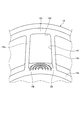
- FIG. 2 is a cross-sectional view for explaining a case where the cage shown in FIG. 1 moves in the axial direction toward the large diameter side of the tapered roller.
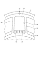
- FIG. 2 is a cross-sectional view for explaining a case where the cage shown in FIG. 1 moves in the axial direction toward the small diameter side of the tapered roller.
- FIG. 16 It is a schematic sectional drawing explaining the opening angle of the circumferential direction side surface of a pillar part. It is a schematic sectional drawing explaining the case where the opening angle of the circumferential direction side surface of a pillar part is 0 degree
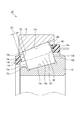
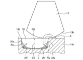
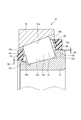
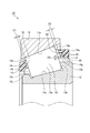
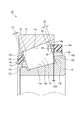
- the tapered roller bearing 10 of this embodiment includes an outer ring 11 having an outer ring raceway surface 11a on an inner peripheral surface, an inner ring 12 having an inner ring raceway surface 12a on an outer peripheral surface, an outer ring raceway surface 11a and an inner ring.
- a plurality of tapered rollers 13 provided so as to be able to roll between the raceway surface 12a, and a cage 14 that holds the plurality of tapered rollers 13 at substantially equal intervals in the circumferential direction.
- the lubricating oil is appropriately supplied into the bearing by a lubricating oil pump P (see FIG. 31) or the like.
- the inner ring 12 has a large collar part 12 b provided at the large diameter side end part of the inner ring 12 and a small collar part 12 c provided at the small diameter side end part of the inner ring 12.
- the outer peripheral surface of the inner ring 12 is formed in a substantially conical shape.
- the tapered roller 13 includes a rolling surface 13 a provided on the circumferential surface of the tapered roller 13, a large diameter side end surface 13 b provided on the large diameter side end portion of the tapered roller 13, and a small diameter side end portion of the tapered roller 13. And a small-diameter side end face 13c provided.
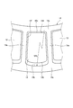
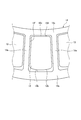
- the cage 14 is made of synthetic resin and is injection-molded by an axial draw.
- the large-diameter annular portion 14a and the small-diameter annular portion 14c are connected in the axial direction, and between the plurality of column portions 14e provided at substantially equal intervals in the circumferential direction and the column portions 14e adjacent to each other in the circumferential direction,
- a pocket 14f is formed surrounded by the diameter-side annular portion 14a and the small-diameter-side annular portion 14c, and holds the tapered roller 13 in a rollable manner.
- the cage 14 has a first gap S1 between the axially inner end surface 14d of the small diameter side annular portion 14c of the cage 14 and the small diameter side end surface 13c of the tapered roller 13. Further, the cage 14 has a second gap S ⁇ b> 2 between the axial inner end surface 14 b of the large-diameter side annular portion 14 a of the cage 14 and the large-diameter side end surface 13 b of the tapered roller 13. Thereby, the retainer 14 is provided to be movable within a predetermined range along the axial direction.
- the axial dimension of the first gap S1 is D1
- the axial dimension of the second gap S2 is D2
- the length dimension of the tapered roller 13 is LR.
- the axial dimensions D1 and D2, the length dimension LR of the tapered roller 13 and the length dimension LP of the pocket 14f are dimensions along the central axis (spinning axis) direction of the tapered roller 13.
- the retainer 14 can freely move in the range of the total dimension Dt of the gap along the axial direction.
- the total dimension Dt of the gaps does not require strict dimension control, and takes into account the general processing accuracy of the cage, and is from 0.1 mm to 1 / of the length dimension LR of the tapered roller 13.
- the range is set to 5 or less.
- the surface of the axially inner end surface (hereinafter also simply referred to as “pocket surface”) 14b of the large-diameter side annular portion 14a of the retainer 14 is formed to be rough, and a specific surface of the axially inner end surface 14b.
- the roughness (arithmetic average roughness) is set to 3 ⁇ m to 20 ⁇ m.
- the surface roughness of the axial inner end surface 14b may be formed to be rougher than the circumferential side surface of the column portion 14e, for example.
- the roughness of the axially inner end surface (pocket surface) 14b of the large-diameter side annular portion 14a functions to guide lubricating oil stored in a groove 20 described later to the tapered roller 13. Thereby, the oil retention capability and oil supply capability of the axial direction inner end surface 14b can be improved. Moreover, it is preferable that the inner surface of the groove 20 to be described later is also roughly formed in order to enhance the oil retaining ability.
- the axial inner end surface 14b is perpendicular to the die-cutting direction at the time of molding the cage, even if the axial inner end surface 14b is formed rough, there is no problem in releasing after molding.
- the surface roughness of the axial inner end surface 14b may be set for all the pockets 14f or may be set for some of the pockets 14f.
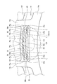
- a plurality of (five in the present embodiment) are formed on the axially inner end surface (pocket surface) 14b of the large-diameter side annular portion 14a of the retainer 14 by groove processing or the like.
- the fine groove (oil retaining portion) 20 is formed.
- One groove 20 may be provided.
- the five grooves 20 are arranged in two rows (two on the outer diameter side and three on the inner diameter side).
- channel 20 is a bottomed groove
- the groove 20 is an oil retaining portion capable of retaining the lubricating oil with a capillary force, and enhances the oil retaining capacity of the retainer 14 and promotes the propagation of the lubricating oil to the tapered roller 13.
- channel 20 may be provided with respect to all the pockets 14f, and may be provided with respect to some pockets 14f.
- the capillary force described in this description is a force in which a solid tries to attract a liquid.
- the surface tension of the solid (retainer) is larger than the surface tension of the liquid (lubricating oil)
- a capillary force is generated and the liquid is attracted to the solid surface.
- the liquid tries to reduce the surface in contact with air due to surface tension. That is, the lubricating oil tends to increase the area in contact with the cage while decreasing the area in contact with air. For this reason, the capillary force increases as the groove of the cage becomes narrower and narrower. Utilizing this principle, in the present invention, the narrow and narrow groove 20 is formed in the pocket surface 14b.
- the groove end portion 20 a is an end portion in the circumferential direction of the groove 20. Further, a groove center portion 20b described later is a center portion in the circumferential direction of the groove 20.
- the groove 20 needs to have a fine shape capable of retaining oil and supplying oil to the tapered roller 13 by the action of capillary force.
- the width and depth of the groove 20 are constant or the groove end.
- the radial width D3 of the groove 20 is set in consideration of the oil retaining property of the lubricating oil in the groove 20, the strength of the cage 14, and the accuracy of general injection molding.
- the maximum portion is set in the range of 0.01 mm to 0.5 mm
- the depth D4 of the groove 20 is set in the range of 0.05 mm in the maximum portion to 1/5 or less of the length dimension LR of the tapered roller 13. .
- the radial width D3 of the groove 20 is a width in a direction orthogonal to the extending direction of the groove 20.
- molded by an axial draw is extended in the same direction (axial direction) as the center axis
- the cage 14 is made of synthetic resin and can be injection-molded by, for example, an axial draw.
- the surface roughness of the inner end surface (pocket surface) 14b in the axial direction of the large-diameter side annular portion 14a and the groove 20 can be simultaneously formed by this injection molding. In this case, it is not necessary to add processing steps, special molding such as two-color molding (double mold), and adhesion of a separately produced oil retaining member. Therefore, the seizure resistance can be improved without substantially increasing the manufacturing cost.
- the material of the cage 14 is not particularly limited, but may be any synthetic resin material having a lipophilicity that has high surface tension with respect to the used lubricating oil and generates capillary force.
- a typical cage resin material you may make the synthetic resin of the holder
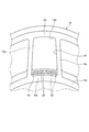
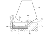
- FIG. 5 is a schematic diagram showing the contact position relationship between the groove end portion 20a in the circumferential direction of the groove 20 and the large-diameter side end surface 13b of the tapered roller 13.
- the large-diameter end surface 13b of the tapered roller 13 is usually provided with a relief recess 13d at the center and an annular contact surface 13e around the relief recess 13d.
- a projection surface of the annular contact surface 13e and the pocket surface 14b (a surface that overlaps when viewed in the longitudinal direction of the tapered roller 13, see the hatched portion in FIG. 5) is a surface on which the tapered roller 13 and the cage 14 can contact. It is.
- At least one of the groove end portions 20a of the five grooves 20 is provided so as to be accommodated in the fan-shaped contact surface 13e. Thereby, it becomes possible to supply the tapered roller 13 with the capillary force with the tapered roller 13 without leaving the lubricating oil collected in the groove end portion 20a by the mechanism described later.
- symbol L is a lubricating oil (a portion provided with a dot pattern).
- FIG. 6A and 6B are explanatory views showing the positional relationship between the longitudinal direction (circumferential direction) of the groove 20 and the tapered roller 13, for example, a cross-sectional view taken along the line B in FIG.
- the depth of the groove 20 is shown enlarged from the actual depth in order to facilitate understanding of the description.
- the cage 14 is characterized in that the lubricating oil stored in the groove 20 by capillary force is supplied to the large-diameter side end surface 13b of the tapered roller 13 by the action of capillary force with the roller surface.
- the groove 20 In order to make this action effective, it is important that the groove 20 generates a high capillary force at a portion where the tapered roller 13 and the pocket surface 14b are in contact with each other. And as one of the methods, in this embodiment, as shown to FIG. 6A, it has comprised so that the groove edge part 20a whose capillary force is higher than the intermediate part of the groove
- FIG. 7A and 7B are explanatory views showing the cross-sectional shape in the radial direction of the groove 20, for example, a cross-sectional view taken along line C in FIG.
- the capillary force works more strongly in a narrow space. Therefore, the radial width D3 of the groove 20 is not only thin, but it should not spread at the opening as shown in FIG. 7B. Therefore, in the present embodiment, as shown in FIG. 7A, the corner 20d between the wall surface (at least one of the radial wall surface and the circumferential wall surface) 20c of the groove 20 and the pocket surface 14b is a sharp edge.
- a circular chamfer with a radius of 0.1 mm or less preferably a circular chamfer with a radius of 0.05 mm or less, or a linear chamfer with a side of 0.1 mm and 45 degrees.
- the groove bottom corner 20e in the radial cross section of the groove 20 is formed in an arc shape, and when the radius Rw of the arc shape of the groove bottom corner 20e is small, the capillary force increases and the lubricating oil enters the groove bottom corner 20e. Acts to stay.
- the radius Rw of the arc shape of the groove bottom corner 20e in the radial section of the groove 20 is 1 ⁇ 4 to the radial width D3 of the groove 20 at the groove center portion 20b that is the center in the longitudinal direction of the groove 20 that is the largest. It is desirable to set it to 1/2. Further, in order to increase the capillary force to the groove end portion 20a, as shown in FIG.
- the arc-shaped radius Rw of the groove bottom corner 20e in the radial cross section of the groove 20 is changed from the groove center portion 20b of the groove 20 to the groove end. It is more desirable to make it smaller (Rw1> Rw2> Rw3) toward the portion 20a. As a result, the lubricating oil accumulated in the groove center portion 20b can be sucked up to the groove end portion 20a having higher capillary force and guided to the pocket surface 14b.
- FIG. 8A and 8B are explanatory views showing a cross-sectional shape of the groove 20 in the longitudinal direction (circumferential direction), for example, a cross-sectional view taken along line B in FIG.
- the depth of the groove 20 is shown enlarged from the actual depth in order to facilitate understanding of the description.
- the radius Rw of the groove bottom corner 20f in the circumferential cross section of the groove 20 is small, the lubricating oil remains in the groove bottom corner 20f, and it becomes difficult to supply the tapered roller 13 with oil.
- the groove bottom corner 20f in the circumferential cross section of the groove 20 is formed in an arc shape, and the depth D4 of the groove 20 is changed from the groove center portion 20b to the groove end portion 20a. It is getting smaller as it goes to. Thereby, the capillary force of the part connected to the pocket surface 14b of the groove end portion 20a can be increased, and the lubricating oil accumulated in the groove bottom can be efficiently sucked up and supplied to the tapered roller 13.
- FIG. 10 is a schematic diagram illustrating an example in which the radial width D3 of the groove 20 is reduced (thinned) at both groove end portions 20a in the longitudinal direction. That is, in the groove 20 shown in FIG. 10, the radial width D3 of the groove end portion 20a is set smaller than the radial width D3 of the groove center portion 20b.
- the narrowed portion is limited to a part of the tip, it is a shape that can easily store a lot of lubricating oil without reducing the space volume of the entire groove.
- FIG. 11 and FIG. 12 are schematic diagrams for explaining another example of the shape of the groove 20.
- the radial width D3 of the groove 20 decreases from the groove center part 20b toward the groove end part 20a, and the depth D4 of the groove 20 extends from the groove center part 20b to the groove end part 20a.
- the radius Rw of the arc shape of the groove bottom corner 20e in the radial cross section of the groove 20 is made smaller (Rw1> Rw2> Rw3) from the groove center portion 20b of the groove 20 toward the groove end portion 20a.
- the capillary force of the portion connected to the pocket surface 14b of the groove end portion 20a can be increased, and the lubricating oil accumulated in the groove bottom can be sucked up efficiently and supplied to the tapered roller 13. It becomes possible.
- the circumferential length of the groove 20, the change in the radial width D3 of the groove 20, the change in the depth D4 of the groove 20, and the change in the radius Rw of the arc shape of the groove bottom corner 20e in the radial cross section of the groove 20 The degree and the continuity / discontinuity of the change can be freely set. Moreover, you may employ
- FIG. 13 is a cross-sectional view showing a state of a radial gap between the cage and the inner ring.
- the cage is a component that rotates in synchronization with the revolution of the roller, and is configured such that movement in the radial direction is restricted by any of the inner ring, the outer ring, and the roller.
- the movement in the radial direction is restricted by the roller, and the roller can be freely moved in the radial direction within a gap provided in the pocket.
- the restriction by rollers there are many factors for variation in the radial position, and it is difficult to intentionally keep the movement amount in the radial direction within a narrow range. And if the movement amount of the cage in the radial direction is increased, the contact position with the pocket surface and the end surface is also greatly displaced, and the effect of refueling is weakened.
- the radial movement of the cage is reduced by adopting a slide bearing structure in which the gap between the inner circumferential surface of the annular portion of the cage and the outer circumferential surface of the flange portion of the inner ring is reduced.
- the cage 14 has a structure in which the inner peripheral surface of the large-diameter side annular portion 14a is guided in the radial direction by the outer peripheral surface of the large collar portion 12b of the inner ring 12, and Both are provided with a structure in which the inner peripheral surface of the small-diameter side annular portion 14c is guided in the radial direction by the outer peripheral surface of the small flange portion 12c of the inner ring 12.
- the present invention is not limited to having both of the two structures described above, and any one of the two structures may be provided.
- the radial movement of the cage is restricted on the outer peripheral surface of the flange portion of the inner ring, and in order to ensure this, the cage is eccentric to the state where it is in contact with the flange portion. Even if it is made to do, although it is in contact with the cage, it has a structure that does not restrain the movement in the radial direction.
- This structure is generally called an inner ring guide retainer.
- the third gap S3 between the inner peripheral surface of the large-diameter side annular portion 14a and the outer peripheral surface of the large collar portion 12b of the inner ring 12 shown in FIG. 13, and the inner peripheral surface and inner ring of the small-diameter side annular portion 14c are shown.
- the fourth gap S4 between the outer periphery of the twelve small flange portions 12c an optimum design is required for each application depending on the size of the bearing, the material of the cage and the bearing, and the operating environment temperature. However, it is optimal to set the gap between the cage and the inner ring to be just zero or leave a slight gap at the lowest temperature in the usage environment.
- the cage resin has a higher linear expansion coefficient than the steel bearing, and the gap decreases at low temperatures.
- the amount of change in the gap increases as the linear expansion coefficient difference, operating temperature range, and cage guide diameter increase.
- a clearance gap with an inner ring becomes negative, a cage
- basket will be restrained by an inner ring and smooth rotation will be inhibited. For this reason, it is important not to make the guide gap negative.
- the gap during use is desirably the minimum, the above-described gap setting is optimal.
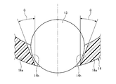
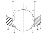
- FIGS. 14 and 15 are cross-sectional views of the tapered roller 13 and the column portion 14e of the cage 14 as seen from the axial direction.
- the column portion 14 e that faces in the circumferential direction across the tapered roller 13 is configured such that the gap on the outer diameter side is narrower than the roller diameter of the tapered roller 13. Therefore, the tapered roller 13 does not fall off from the pocket 14f.
- the roller In the state where the bearing is incorporated in the equipment to be used, the roller is sandwiched between the inner ring and the outer ring, so the roller will not fall off even if there is no cage, but until the assembly to the equipment to be used, that is, the inner ring, roller, cage When the assembly is separated from the outer ring, the above structure is employed so that the assembly will not be disassembled.
- the cage has a larger component force in the radial direction of the cage, which is generated from the force in the roller revolution direction received by contact with the roller. Since the roller behavior is uneven among the rollers, the force in the radial direction of the cage generated in all pockets of the cage is also uneven, which causes the cage center axis to deviate from the rotation center axis.
- the contact position between the pocket surface 14b and the end surface on the large diameter side of the tapered roller 13 is also displaced, so this displacement of the cage center axis should be suppressed as much as possible.
- the opening angle ⁇ of the circumferential side surface 14h of the column portion 14e constituting the pocket 14f is set to 0 ° to 40 °.
- the structure of a low opening angle such as 0 degrees is provided with a protrusion 14i that narrows the window width to prevent the roller from falling off at the radially outer end of the circumferential side surface 14h of the column portion 14e. It can be realized by separating the roller drop-off prevention part and the contact position of the pillar part in use.
- the large-diameter side end surface 13b of the tapered roller 13 and the pocket surface 14b are brought into contact with each other by a fan-shaped contact surface 13e of the tapered roller 13, and the inside of the contact surface 13e. Since the lubricating oil is supplied from the groove end portion 20a to the tapered roller 13 by capillary force, it is necessary to bring the groove end portion 20a and the large-diameter side end surface 13b of the tapered roller 13 into contact with each other.
- the axially inner end surface (pocket surface) 14b of the large-diameter side annular portion 14a is the large-diameter side end surface 13b of the tapered roller 13.
- the projection surface of the projection surface of the pocket surface 14b more than half of the groove end portions 20a of the five grooves 20 provided in the pocket surface 14b can be in contact with the large-diameter side end surface 13b of the tapered roller 13 at the same time. It is desirable to be formed. In the case of FIG.
- the five grooves 20 are arranged in two rows (two on the outer diameter side and three on the inner diameter side), and among the ten groove end portions 20a in total, six groove end portions 20 a is in contact with the large diameter side end surface 13 b of the tapered roller 13.
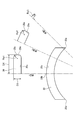
- FIG. 16 and 17 are diagrams showing the surface shapes of the large-diameter side end surface 13b and the pocket surface 14b of the tapered roller 13.
- FIG. 16 and 17 are diagrams showing the surface shapes of the large-diameter side end surface 13b and the pocket surface 14b of the tapered roller 13.
- the roller of the tapered roller bearing has a structure in which the cone angle vertices of the outer diameters of all the rollers are gathered at one point (cone center) on the bearing central axis.
- the large-diameter end surface 13b of the tapered roller 13 is formed in a convex spherical shape having a radius Ra from the cone center.
- the pocket surface is flat or conical, and the adhesion with the large diameter side end surface of the tapered roller is not considered, but in the present invention, the tapered roller 13 is used.
- the pocket surface 14b is used to minimize the gap between the large-diameter side end surface 13b of the tapered roller 13 and the pocket surface 14b. Is preferably formed in a concave spherical shape.
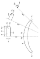
- FIGS. 18 and 19 are diagrams showing a first modification of the surface shape of the pocket surface 14b.
- the pocket surface 14b is formed in a concave shape along the circumferential direction.
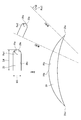
- FIGS. 20 and 21 are diagrams showing a second modification of the surface shape of the pocket surface 14b.
- the pocket surface 14b is formed in a concave shape along the radial direction.
- FIGS. 18 to 21 are examples in which the pocket surface 14b is not formed into a concave spherical shape, but even in this case, an effect close to a concave spherical shape can be obtained. These examples are effective when spherical machining is extremely difficult or impossible due to the convenience of the mold manufacturing method.
- the tapered roller bearing 10 of the present invention moves the retainer 14 using the component force of its own weight, and therefore is used for a structure that supports a horizontally provided shaft (horizontal axis). Is preferred.
- the surface of the inner end surface 14b in the axial direction of the large-diameter side annular portion 14a of the cage 14 is formed rough, and the large-diameter side annular portion 14a
- a groove (oil retaining portion) 20 that retains lubricating oil by capillary force is provided on the axial inner end surface 14b, and when the retainer 14 moves in the axial direction toward the small diameter side of the tapered roller 13, the groove 20 is tapered. 13 is in contact with the large-diameter side end surface 13b, so that seizure of the bearing 10 can be prevented even in a lubricating environment of a small amount of lubricating oil.
- the groove 20 is separated from the large diameter side end surface 13b of the tapered roller 13, and the large diameter side annular portion in which the groove 20 is formed. Since 14a does not always contact the tapered roller 13, an increase in frictional resistance during rotation of the bearing can be suppressed, and wear of the large-diameter side annular portion 14a in which the groove 20 is formed can be suppressed. Further, it is not necessary to manage advanced component dimensional accuracy and the like, and an increase in manufacturing cost can be suppressed.
- the large-diameter side annular portion 14a in which the groove 20 is formed does not have a contact force (pressing force) set in advance, and the tapered roller 13 is generated by the component force of the weight of the cage 14. Therefore, the frictional resistance is hardly generated and the wear deterioration of the large-diameter side annular portion 14a can be minimized.
- the cage 14 is made of synthetic resin, and the surface roughness and the groove 20 of the axially inner end surface 14b of the large-diameter side annular portion 14a of the cage 14 are formed. Since it is injection-molded simultaneously with the retainer 14 by the axial draw, an increase in manufacturing cost can be suppressed.
- the groove 20 is formed along the circumferential direction, and since the acting direction of the centrifugal force during rotation of the bearing and the forming direction of the groove 20 are orthogonal to each other, the groove 20 is held in the groove 20. It is possible to prevent the lubricating oil from scattering due to centrifugal force.
- the amount of lubricating oil can be greatly reduced, so that the stirring resistance of the lubricating oil can be reduced.
- the lubricating oil pump and the oil supply passage can be eliminated, thereby reducing the weight and compactness of the entire system, Cost reduction can be achieved.
- the lubricant is intermittently supplied into the bearing, or the bearing is prevented from seizing even in a lubrication environment in which the lubricant in the bearing is very small. Performance and lubrication effect can be maintained over a long period of time.
- the tapered roller bearing 10 of the present embodiment can be suitably used for a mechanism in which the lubricating oil pump temporarily stops when the engine is stopped, such as a transmission of some hybrid vehicles. It is possible to cope with a situation where it is difficult to sufficiently supply the lubricating oil because the lubricating oil pump does not operate when towed.
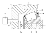
- the outer ring 11 of the tapered roller bearing 10 is fitted in the housing H, and the inner ring 12 is fitted on the rotary shaft A, as shown in FIG.
- a structure in which an oil supply path R communicating with the bearing 10 is provided in H and a lubricating oil pump P is connected to the oil supply path R is generally known.
- the lubricating oil pumped from the lubricating oil pump P is supplied to the bearing 10 through the oil supply path R.
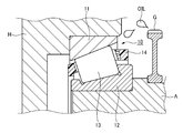
- the structure in which the lubricating oil is splashed by the gear G is such that the outer ring 11 of the tapered roller bearing 10 is fitted in the housing H, and the inner ring 12 is fitted on the rotating shaft A, so that A structure in which a gear G is provided on the shaft A adjacent to the inner ring 12 is generally known.
- the lubricating oil adhering to the gear G is scattered by the centrifugal force accompanying the shaft rotation, and the scattered lubricating oil adheres to the bearing 10 and is supplied.
- a lubricating oil amount of about 50 cc / min to 1000 cc / min is supplied in order to prevent seizure of the bearing.
- the amount of the lubricating oil is less than 10 cc / min, heat generation or seizure is likely to occur due to an oil film shortage accompanying the lack of lubricating oil, and seizure occurs at 0 cc / min (non-lubricating oil).
- the present invention is applicable to a lean lubrication state, not a non-lubricated state, and is highly effective in a lubrication environment where the amount of lubricating oil is small, specifically, in a lean lubrication state of about 0.01 cc / min to 10 cc / min. Demonstrate.
- the time until seizure is related to the amount of oil retained in the oil retaining part, so by increasing the amount of oil retained, the unlubricated application time can be extended significantly from several tens of minutes to several hours. Is possible. Expansion of the oil retention amount can be dealt with, for example, by increasing the number of oil grooves or expanding the oil groove depth.
- a passenger car may be towed as an auxiliary vehicle at a destination of a large vehicle such as a camper when a failure occurs.
- a large vehicle such as a camper
- a preload is generally applied because it is generally applied with a preload. In this idling state, the engine and the electric lubricating oil pump do not operate and the lubricating oil pump is stopped, so that the bearing is likely to seize.
- the bearing can be supplied with oil until there is no lubricating oil stored in the oil retaining portion, so that seizure resistance is maintained even in a towed state where the splashing is insufficient or there is no splashing. Can greatly improve the performance.
- the groove 20 circulates in a semicircular shape within the axially inner end surface 14b (inside the pocket 14f) of the large-diameter side annular portion 14a. It may be formed.
- the groove 20 is arranged concentrically with the central axis of the tapered roller 13. For this reason, the tapered roller 13 improves the familiarity of the oil film of the groove 20 and the lubricating oil is not easily shaken off against the centrifugal force accompanying the rotation of the bearing. Therefore, the lubricating oil held in the groove 20 is caused by the centrifugal force. It is possible to suppress scattering.
- channel 20 is opened to the inner peripheral surface of the large diameter side annular part 14a and is not opened to the outer peripheral surface side of the large diameter side annular part 14a, the oil retaining property of the groove 20 can be improved.
- the groove 20 formed in a semicircular shape is formed by two grooves in a shape that is divided at the center thereof, and the end of the groove 20 is in contact with the large-diameter side end face 13 b of the tapered roller 13. It is like that.
- the groove 20 is linear and circumferential in the radial direction within the axial inner end surface 14b (inside the pocket 14f) of the large-diameter side annular portion 14a. It may be formed in parallel with the direction. Moreover, the groove
- a plurality of (this modification) is provided in the axially inner end face 14b (in the pocket 14f) of the large-diameter side annular portion 14a instead of the groove 20.
- seven holes 21 may be formed.
- the hole 21 is a tear-shaped bottomed hole as viewed in the axial direction, the width (minor diameter side) D5 of the hole 21 is set in the range of 0.01 mm to 0.5 mm, and the depth D6 of the hole 21 is It is set within a range from 0.05 mm to 1/5 or less of the length dimension LR of the tapered roller 13.
- lubricating oil can be held while suppressing a decrease in strength of the cage 14.
- the hole 21 only needs to have a narrowed part in the opening, and is not limited to the teardrop shape, but may be a polygonal shape such as a lemon shape or a triangle shape, or a combination thereof. May be.
- a plurality of the grooves 20 described above are formed on the axially inner end surface (pocket surface) 14 b of the large-diameter side annular portion 14 a of the retainer 14. It is formed in parallel along the circumferential direction. Further, the surface of the inner peripheral surface 14g of the large-diameter side annular portion 14a of the retainer 14 is formed to be rough, and a plurality (six in this embodiment) are provided on the inner peripheral surface 14g of the large-diameter side annular portion 14a.
- An annular groove (oil retaining portion) 30 is formed. The annular groove 30 is formed so as to be linear in the axial direction and parallel to the circumferential direction.
- the annular portion groove 30 is formed so as to penetrate the large-diameter-side annular portion 14a in the axial direction in consideration of pullability at the time of mold release after molding.
- the annular groove 30 may be provided for all the pockets 14f or may be provided for some of the pockets 14f.
- the surface roughness of the inner peripheral surface 14g of the large-diameter side annular portion 14a is set to 3 ⁇ m to 20 ⁇ m similarly to the axial inner end surface 14b.
- the width D7 of the annular groove 30 is set in the range of 0.01 mm to 0.5 mm, and the depth D8 (see FIG. 26) of the annular groove 30 is 0.05 mm to the larger diameter side of the tapered roller 13. It is set to a range of 1/5 or less of the outer diameter Dr (see FIG. 1) of the end.
- the surfaces of the inner end surface 14b and the inner peripheral surface 14g in the axial direction of the large-diameter-side annular portion 14a of the cage 14 are formed rough, and the large-diameter side
- the groove 20 is formed on the axial inner end surface 14b of the annular portion 14a, and the annular portion groove 30 is formed on the inner peripheral surface 14g of the large-diameter side annular portion 14a.
- the annular portion groove 30 is formed on the axially outer end portion of the annular portion groove 30 in accordance with optimization to the injection mold. You may provide the dam part 31 which plugs up the axial direction outer end opening.
- the depth D8 of the annular groove 30 is gradually made shallower toward the outside in the axial direction in accordance with the optimization to the injection mold.
- the bottom surface of the annular groove 30 may be inclined so that the depth becomes zero at the outer end in the axial direction.
- the width D7 of the annular groove 30 may be gradually narrowed outward in the axial direction, or both may be changed.
- a plurality of grooves 20 are provided on the axially inner end surface (pocket surface) 14b of the large-diameter side annular portion 14a.
- the circumferential groove 32 which connects the annular part groove
- an annular groove 30 can be added between the adjacent pockets 14f.
- the lubricating oil widely held by the large-diameter side annular portion 14a can be supplied to the pocket 14f side.
- the circumferential groove 32 is forcibly removed from the mold, so the depth of the circumferential groove 32 is in the range of 0.05 mm to 2 mm, and the width of the circumferential groove 32 is 0.5 mm.
- the width of the 14 large-diameter side annular portion 14a is set within a range of ⁇ 1 mm.
- a plurality of step portions are provided in the axial inner end surface 14 b (in the pocket 14 f) of the large-diameter side annular portion 14 a of the retainer 14 instead of the groove 20.
- the step part 40 which consists of is formed.
- the staircase portion 40 is an oil retaining portion capable of holding the lubricating oil with a capillary force. Further, the staircase portion 40 is formed in a shape that is divided at its central portion.
- an annular groove 30 similar to that of the first modification of the second embodiment (see FIG. 26) is formed on the inner peripheral surface 14g of the large-diameter annular portion 14a of the cage 14. Has been.
- the staircase portion 40 and the annular groove 30 may be provided for all the pockets 14f or may be provided for some of the pockets 14f.
- the plurality of stepped portions of the staircase portion 40 are formed in parallel along the circumferential direction on the axially inner end surface 14b of the large-diameter side annular portion 14a.
- the step portion is provided with a step end portion at a position in contact with the tapered roller 13, and the capillary radius is reduced by making the curvature radius of the step portion corner of the step end portion smaller than that of the step center portion.
- the width (diameter dimension) D9 of one step portion is set in a range of 0.01 mm to 0.5 mm
- the height (axial dimension) D10 of one step portion is 0.01 mm to 0.00 mm. The range is set to 5 mm.
- the surface of the staircase portion 40 is formed to be rough, and the surface roughness is set to 3 ⁇ m to 20 ⁇ m. Further, the inner peripheral surface 14g of the large-diameter side annular portion 14a is also formed rough, and the surface roughness is set to 3 ⁇ m to 20 ⁇ m.
- the staircase portion 40 is formed on the axially inner end surface 14b of the large-diameter-side annular portion 14a of the retainer 14, and the surface of the staircase portion 40 is formed. Is formed with a rough surface, the surface of the inner peripheral surface 14g of the large-diameter-side annular portion 14a is formed rough, and a plurality of annular portion grooves 30 are formed on the inner peripheral surface 14g, and the capillary end is enhanced.
- the portion is in contact with the tapered roller 13, the oil retaining ability and the oil supplying ability of the cage 14 can be increased, and seizure of the bearing 10 can be further prevented.
- the staircase portion 40 is formed along the circumferential direction, and the direction in which the centrifugal force is applied during rotation of the bearing and the formation direction of the staircase portion 40 are orthogonal. It is possible to prevent the lubricating oil held in the air from being scattered by centrifugal force. Moreover, since the strength conditions for the injection mold of the cage 14 are relaxed, an increase in manufacturing cost can be further suppressed. About another structure and an effect, it is the same as that of the said 1st and 2nd embodiment.
- the test conditions were as follows: a single row tapered roller bearing with a cage press cage ( ⁇ 25 ⁇ ⁇ 55 ⁇ 17) was mounted on the horizontal axis (horizontal axis), the test load was 4 kN axial load, the rotational speed was 5,000 rpm, and the lubricating oil The hydraulic oil (VG32) was used for the test, and 5 ml of lubricating oil was dropped before the test was started.
- the cage is formed by three-dimensional modeling (3D printing), and the surface roughness of the inner end surface (pocket surface) in the axial direction of the large-diameter side annular portion is 2 ⁇ m, and the four rows are arranged in the circumferential direction. 2 (the two rows of grooves shown in FIG. 2 are four rows, the groove width: 0.2 mm, the groove depth: 0.5 mm).
- the test was performed twice, and seizure occurred in 86 seconds for the first time and 71 seconds for the second time.
- seizure did not occur until 1271 seconds for the first time and 997 seconds for the second time, and the seizure occurrence time could be extended. Therefore, the effectiveness of the oil retaining part (groove) of the present invention was demonstrated.
Landscapes
- Engineering & Computer Science (AREA)
- General Engineering & Computer Science (AREA)
- Mechanical Engineering (AREA)
- Chemical & Material Sciences (AREA)
- Oil, Petroleum & Natural Gas (AREA)
- Rolling Contact Bearings (AREA)
Abstract
Priority Applications (5)
| Application Number | Priority Date | Filing Date | Title |
|---|---|---|---|
| CN201980018295.6A CN111868400B (zh) | 2018-03-09 | 2019-03-08 | 圆锥滚子轴承 |
| KR1020207025982A KR102478695B1 (ko) | 2018-03-09 | 2019-03-08 | 원추 롤러 베어링 |
| JP2020504070A JP7306372B2 (ja) | 2018-03-09 | 2019-03-08 | 円すいころ軸受 |
| US16/979,041 US11306774B2 (en) | 2018-03-09 | 2019-03-08 | Tapered roller bearing |
| EP19764186.3A EP3763958B1 (fr) | 2018-03-09 | 2019-03-08 | Roulements à rouleaux coniques |
Applications Claiming Priority (2)
| Application Number | Priority Date | Filing Date | Title |
|---|---|---|---|
| JP2018043540 | 2018-03-09 | ||
| JP2018-043540 | 2018-03-09 |
Publications (1)
| Publication Number | Publication Date |
|---|---|
| WO2019172446A1 true WO2019172446A1 (fr) | 2019-09-12 |
Family
ID=67846672
Family Applications (1)
| Application Number | Title | Priority Date | Filing Date |
|---|---|---|---|
| PCT/JP2019/009490 WO2019172446A1 (fr) | 2018-03-09 | 2019-03-08 | Roulements à rouleaux coniques |
Country Status (6)
| Country | Link |
|---|---|
| US (1) | US11306774B2 (fr) |
| EP (1) | EP3763958B1 (fr) |
| JP (1) | JP7306372B2 (fr) |
| KR (1) | KR102478695B1 (fr) |
| CN (1) | CN111868400B (fr) |
| WO (1) | WO2019172446A1 (fr) |
Cited By (5)
| Publication number | Priority date | Publication date | Assignee | Title |
|---|---|---|---|---|
| WO2020246589A1 (fr) * | 2019-06-05 | 2020-12-10 | Ntn株式会社 | Roulement à rouleaux coniques |
| DE102019213988A1 (de) * | 2019-09-13 | 2021-03-18 | Minebea Mitsumi Inc. | Lagerkäfig, insbesondere Axiallagerkäfig |
| DE102019213992A1 (de) * | 2019-09-13 | 2021-03-18 | Minebea Mitsumi Inc. | Lagerkäfig, insbesondere Radiallagerkäfig |
| WO2022039041A1 (fr) * | 2020-08-19 | 2022-02-24 | Ntn株式会社 | Dispositif de retenue de résine pour roulement à rouleaux coniques, et roulement à rouleaux coniques |
| WO2023120639A1 (fr) * | 2021-12-23 | 2023-06-29 | Ntn株式会社 | Roulement à rouleau conique |
Citations (19)
| Publication number | Priority date | Publication date | Assignee | Title |
|---|---|---|---|---|
| JPS5427256U (fr) | 1977-07-27 | 1979-02-22 | ||
| JPH01168014U (fr) * | 1988-05-16 | 1989-11-27 | ||
| JPH0587326U (ja) * | 1992-04-27 | 1993-11-26 | エヌティエヌ株式会社 | 円筒ころ軸受 |
| JPH076524U (ja) * | 1993-06-30 | 1995-01-31 | エヌティエヌ株式会社 | ころ軸受用保持器 |
| JPH08184318A (ja) | 1994-12-28 | 1996-07-16 | Ntn Corp | 転がり軸受用保持器 |
| JPH08200376A (ja) * | 1995-01-27 | 1996-08-06 | Koyo Seiko Co Ltd | ころ軸受用の保持器 |
| JPH09203414A (ja) * | 1996-01-24 | 1997-08-05 | Hitachi Constr Mach Co Ltd | ころ軸受用保持器 |
| JP2000130443A (ja) * | 1998-10-26 | 2000-05-12 | Ntn Corp | 円すいころ軸受および円すいころ軸受用保持器 |
| JP2003294038A (ja) * | 2002-04-01 | 2003-10-15 | Nsk Ltd | 円すいころ軸受 |
| JP2007032612A (ja) * | 2005-07-22 | 2007-02-08 | Nsk Ltd | ころ軸受 |
| JP2008069875A (ja) * | 2006-09-14 | 2008-03-27 | Ntn Corp | 円錐ころ軸受 |
| WO2008087926A1 (fr) | 2007-01-15 | 2008-07-24 | Jtekt Corporation | Roulement à rouleaux coniques |
| DE102009055660A1 (de) * | 2009-11-24 | 2011-05-26 | Schaeffler Technologies Gmbh & Co. Kg | Wälzlagerkäfig mit Schmiermitteltaschen |
| JP2011202714A (ja) * | 2010-03-25 | 2011-10-13 | Ntn Corp | 風力発電装置主軸用円すいころ軸受 |
| JP5668420B2 (ja) | 2009-11-17 | 2015-02-12 | 日本精工株式会社 | 円すいころ軸受及び円すいころ軸受用保持器の製造方法 |
| JP2015183804A (ja) * | 2014-03-25 | 2015-10-22 | 株式会社ジェイテクト | 保持器ユニットおよび該保持器ユニットを備えた円錐ころ軸受 |
| JP2016142382A (ja) * | 2015-02-04 | 2016-08-08 | 株式会社ジェイテクト | 分割保持器およびころ軸受 |
| JP2017166641A (ja) * | 2016-03-17 | 2017-09-21 | 日本精工株式会社 | 円錐ころ軸受用保持器、円錐ころ軸受 |
| JP2018043540A (ja) | 2016-09-12 | 2018-03-22 | トヨタ紡織株式会社 | シート操作システム及び線状部材作動装置 |
Family Cites Families (26)
| Publication number | Priority date | Publication date | Assignee | Title |
|---|---|---|---|---|
| US1011029A (en) * | 1910-10-15 | 1911-12-05 | Star Ball Retainer Company | Roller-bearing. |
| US2219031A (en) * | 1937-12-01 | 1940-10-22 | Bantam Bearings Corp | Bearing construction |
| US2867076A (en) * | 1957-05-16 | 1959-01-06 | Herr Mfg Co Inc | Lubrication of spinning rings |
| JPS5427256A (en) | 1977-08-02 | 1979-03-01 | Asahi Glass Co Ltd | Method of removing nitrogen content in drainage |
| US4400040A (en) * | 1981-11-16 | 1983-08-23 | The Timken Company | Tapered roller bearing with improved lubricating means |
| JPH03113U (fr) * | 1989-05-22 | 1991-01-07 | ||
| JP3699249B2 (ja) * | 1997-07-28 | 2005-09-28 | Ntn株式会社 | ハブユニット軸受およびその製造方法 |
| JP4526739B2 (ja) | 2001-07-11 | 2010-08-18 | 中西金属工業株式会社 | 円錐ころ軸受用保持器の製造方法 |
| JP3747006B2 (ja) * | 2002-03-28 | 2006-02-22 | Ntn株式会社 | ころ軸受用保持器及びころ軸受 |
| JP2004293700A (ja) * | 2003-03-27 | 2004-10-21 | Ntn Corp | 円すいころ軸受 |
| JP4149350B2 (ja) | 2003-10-15 | 2008-09-10 | Ntn株式会社 | 円すいころ軸受および円すいころ軸受用保持器 |
| JP2007040512A (ja) | 2005-06-29 | 2007-02-15 | Nsk Ltd | 円錐ころ軸受 |
| DE602006018399D1 (de) * | 2005-08-25 | 2011-01-05 | Ntn Toyo Bearing Co Ltd | Kegelrollenlager |
| JP2008256168A (ja) * | 2007-04-09 | 2008-10-23 | Jtekt Corp | 転がり軸受用保持器およびそれを具備した風力発電用軸受 |
| JP2009058039A (ja) * | 2007-08-31 | 2009-03-19 | Jtekt Corp | 転がり軸受用保持器 |
| WO2011062188A1 (fr) | 2009-11-17 | 2011-05-26 | 日本精工株式会社 | Palier à roulement conique et procédé de fabrication d'une cabine pour un palier à roulement conique |
| JP2012251571A (ja) * | 2011-05-31 | 2012-12-20 | Nsk Ltd | 円すいころ軸受用保持器及び円すいころ軸受 |
| JP6357782B2 (ja) * | 2013-07-31 | 2018-07-18 | 日本精工株式会社 | 円すいころ軸受 |
| JP6458458B2 (ja) | 2013-12-25 | 2019-01-30 | 株式会社ジェイテクト | 円すいころ軸受 |
| JP6520061B2 (ja) | 2013-12-25 | 2019-05-29 | 株式会社ジェイテクト | 玉軸受 |
| JP6458459B2 (ja) | 2013-12-25 | 2019-01-30 | 株式会社ジェイテクト | 円すいころ軸受 |
| JP6256023B2 (ja) * | 2014-01-16 | 2018-01-10 | 株式会社ジェイテクト | 円すいころ軸受及び動力伝達装置 |
| JP6442837B2 (ja) | 2014-03-10 | 2018-12-26 | 株式会社ジェイテクト | 円錐ころ軸受 |
| JP6550898B2 (ja) * | 2015-04-28 | 2019-07-31 | 株式会社ジェイテクト | 転がり軸受 |
| JP6776536B2 (ja) | 2016-01-14 | 2020-10-28 | 株式会社ジェイテクト | 円すいころ軸受 |
| DE102016222711A1 (de) * | 2016-11-18 | 2018-05-24 | Schaeffler Technologies AG & Co. KG | Kegelrollenlager |
-
2019
- 2019-03-08 KR KR1020207025982A patent/KR102478695B1/ko active IP Right Grant
- 2019-03-08 CN CN201980018295.6A patent/CN111868400B/zh active Active
- 2019-03-08 EP EP19764186.3A patent/EP3763958B1/fr active Active
- 2019-03-08 JP JP2020504070A patent/JP7306372B2/ja active Active
- 2019-03-08 US US16/979,041 patent/US11306774B2/en active Active
- 2019-03-08 WO PCT/JP2019/009490 patent/WO2019172446A1/fr active Application Filing
Patent Citations (19)
| Publication number | Priority date | Publication date | Assignee | Title |
|---|---|---|---|---|
| JPS5427256U (fr) | 1977-07-27 | 1979-02-22 | ||
| JPH01168014U (fr) * | 1988-05-16 | 1989-11-27 | ||
| JPH0587326U (ja) * | 1992-04-27 | 1993-11-26 | エヌティエヌ株式会社 | 円筒ころ軸受 |
| JPH076524U (ja) * | 1993-06-30 | 1995-01-31 | エヌティエヌ株式会社 | ころ軸受用保持器 |
| JPH08184318A (ja) | 1994-12-28 | 1996-07-16 | Ntn Corp | 転がり軸受用保持器 |
| JPH08200376A (ja) * | 1995-01-27 | 1996-08-06 | Koyo Seiko Co Ltd | ころ軸受用の保持器 |
| JPH09203414A (ja) * | 1996-01-24 | 1997-08-05 | Hitachi Constr Mach Co Ltd | ころ軸受用保持器 |
| JP2000130443A (ja) * | 1998-10-26 | 2000-05-12 | Ntn Corp | 円すいころ軸受および円すいころ軸受用保持器 |
| JP2003294038A (ja) * | 2002-04-01 | 2003-10-15 | Nsk Ltd | 円すいころ軸受 |
| JP2007032612A (ja) * | 2005-07-22 | 2007-02-08 | Nsk Ltd | ころ軸受 |
| JP2008069875A (ja) * | 2006-09-14 | 2008-03-27 | Ntn Corp | 円錐ころ軸受 |
| WO2008087926A1 (fr) | 2007-01-15 | 2008-07-24 | Jtekt Corporation | Roulement à rouleaux coniques |
| JP5668420B2 (ja) | 2009-11-17 | 2015-02-12 | 日本精工株式会社 | 円すいころ軸受及び円すいころ軸受用保持器の製造方法 |
| DE102009055660A1 (de) * | 2009-11-24 | 2011-05-26 | Schaeffler Technologies Gmbh & Co. Kg | Wälzlagerkäfig mit Schmiermitteltaschen |
| JP2011202714A (ja) * | 2010-03-25 | 2011-10-13 | Ntn Corp | 風力発電装置主軸用円すいころ軸受 |
| JP2015183804A (ja) * | 2014-03-25 | 2015-10-22 | 株式会社ジェイテクト | 保持器ユニットおよび該保持器ユニットを備えた円錐ころ軸受 |
| JP2016142382A (ja) * | 2015-02-04 | 2016-08-08 | 株式会社ジェイテクト | 分割保持器およびころ軸受 |
| JP2017166641A (ja) * | 2016-03-17 | 2017-09-21 | 日本精工株式会社 | 円錐ころ軸受用保持器、円錐ころ軸受 |
| JP2018043540A (ja) | 2016-09-12 | 2018-03-22 | トヨタ紡織株式会社 | シート操作システム及び線状部材作動装置 |
Non-Patent Citations (1)
| Title |
|---|
| See also references of EP3763958A4 |
Cited By (6)
| Publication number | Priority date | Publication date | Assignee | Title |
|---|---|---|---|---|
| WO2020246589A1 (fr) * | 2019-06-05 | 2020-12-10 | Ntn株式会社 | Roulement à rouleaux coniques |
| US11841051B2 (en) | 2019-06-05 | 2023-12-12 | Ntn Corporation | Tapered roller bearing |
| DE102019213988A1 (de) * | 2019-09-13 | 2021-03-18 | Minebea Mitsumi Inc. | Lagerkäfig, insbesondere Axiallagerkäfig |
| DE102019213992A1 (de) * | 2019-09-13 | 2021-03-18 | Minebea Mitsumi Inc. | Lagerkäfig, insbesondere Radiallagerkäfig |
| WO2022039041A1 (fr) * | 2020-08-19 | 2022-02-24 | Ntn株式会社 | Dispositif de retenue de résine pour roulement à rouleaux coniques, et roulement à rouleaux coniques |
| WO2023120639A1 (fr) * | 2021-12-23 | 2023-06-29 | Ntn株式会社 | Roulement à rouleau conique |
Also Published As
| Publication number | Publication date |
|---|---|
| JP7306372B2 (ja) | 2023-07-11 |
| KR102478695B1 (ko) | 2022-12-16 |
| JPWO2019172446A1 (ja) | 2021-02-25 |
| CN111868400B (zh) | 2022-06-21 |
| EP3763958B1 (fr) | 2023-02-15 |
| CN111868400A (zh) | 2020-10-30 |
| US11306774B2 (en) | 2022-04-19 |
| KR20200117025A (ko) | 2020-10-13 |
| EP3763958A4 (fr) | 2021-04-28 |
| US20210054877A1 (en) | 2021-02-25 |
| EP3763958A1 (fr) | 2021-01-13 |
Similar Documents
| Publication | Publication Date | Title |
|---|---|---|
| WO2019172446A1 (fr) | Roulements à rouleaux coniques | |
| WO2010150707A1 (fr) | Support en résine synthétique pour roulements à billes à gorge profonde, roulement à billes à gorge profonde, et dispositif de support d'engrenage | |
| JP2007032612A (ja) | ころ軸受 | |
| US20150192176A1 (en) | Rolling bearing for a turbocharger | |
| EP2562437A2 (fr) | Roulement à billes à contact angulaire | |
| JP2012041940A (ja) | 円筒ころ軸受の保持器及び円筒ころ軸受 | |
| JP6234137B2 (ja) | 深みぞ玉軸受 | |
| WO2021039532A1 (fr) | Palier de roulement effilé | |
| JP2006071016A (ja) | 玉軸受用保持器 | |
| JP2002515105A (ja) | 自己ポンプ作動ローラーベアリング | |
| WO2019172447A1 (fr) | Roulement à rouleaux coniques | |
| JP7272175B2 (ja) | 円すいころ軸受 | |
| WO2019235578A1 (fr) | Roulement à billes | |
| JP2007032768A (ja) | ころ軸受 | |
| JP2021032360A (ja) | ラジアル型ころ軸受 | |
| JP7466501B2 (ja) | 円すいころ軸受 | |
| JPH08200376A (ja) | ころ軸受用の保持器 | |
| JP2021060071A (ja) | 円すいころ軸受 | |
| JP2007040512A (ja) | 円錐ころ軸受 | |
| JP7272176B2 (ja) | 円すいころ軸受 | |
| WO2023090208A1 (fr) | Roulement à rouleaux coniques | |
| JP2003254338A (ja) | 円すいころ軸受 | |
| JP2011196393A (ja) | スラストころ軸受 | |
| JP2021032359A (ja) | ラジアル型ころ軸受 | |
| JP2021085500A (ja) | ラジアル型ころ軸受 |
Legal Events
| Date | Code | Title | Description |
|---|---|---|---|
| 121 | Ep: the epo has been informed by wipo that ep was designated in this application |
Ref document number: 19764186 Country of ref document: EP Kind code of ref document: A1 |
|
| ENP | Entry into the national phase |
Ref document number: 2020504070 Country of ref document: JP Kind code of ref document: A |
|
| ENP | Entry into the national phase |
Ref document number: 20207025982 Country of ref document: KR Kind code of ref document: A |
|
| NENP | Non-entry into the national phase |
Ref country code: DE |
|
| WWE | Wipo information: entry into national phase |
Ref document number: 2019764186 Country of ref document: EP |